

Page 1
MG331-21-VAVCAV
r
VAV System
Description
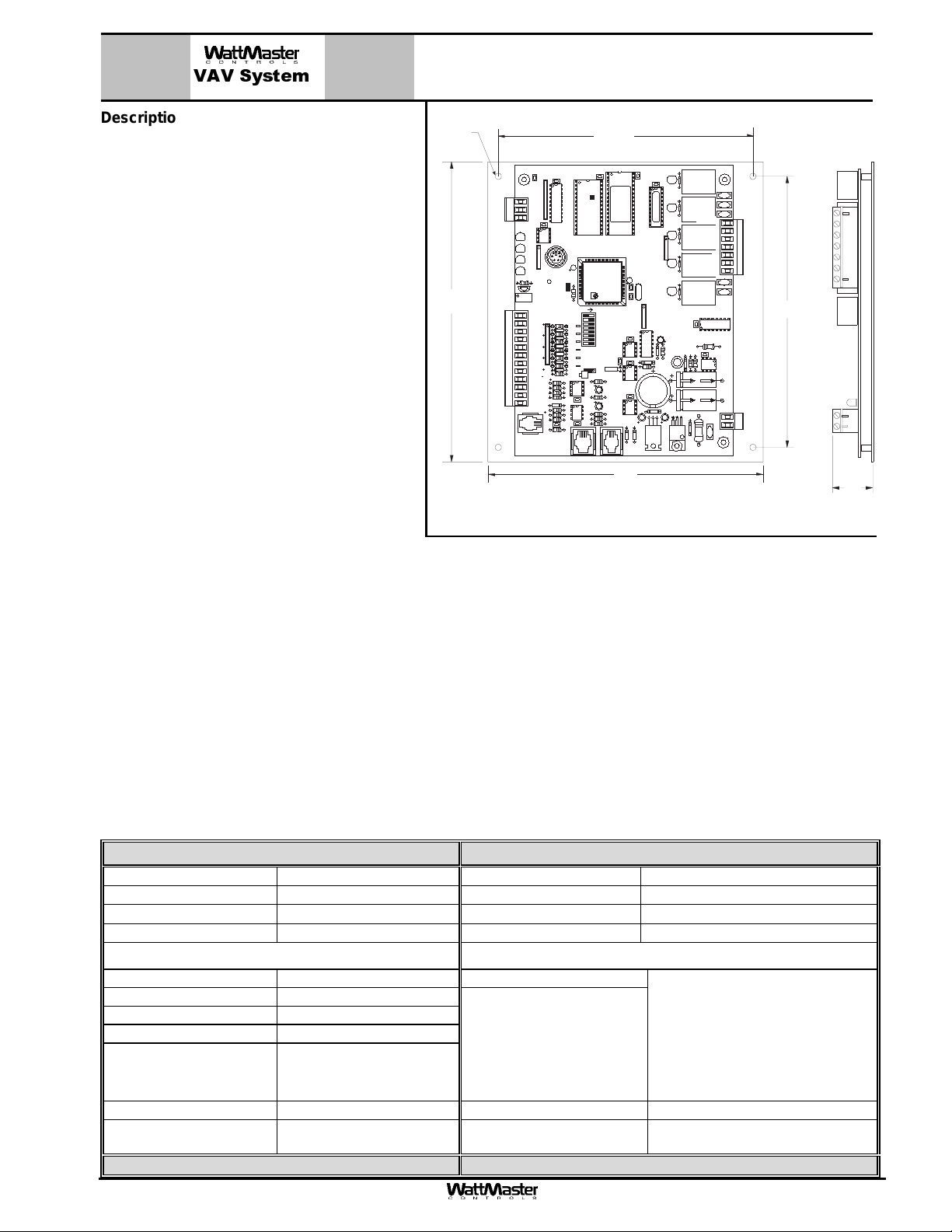
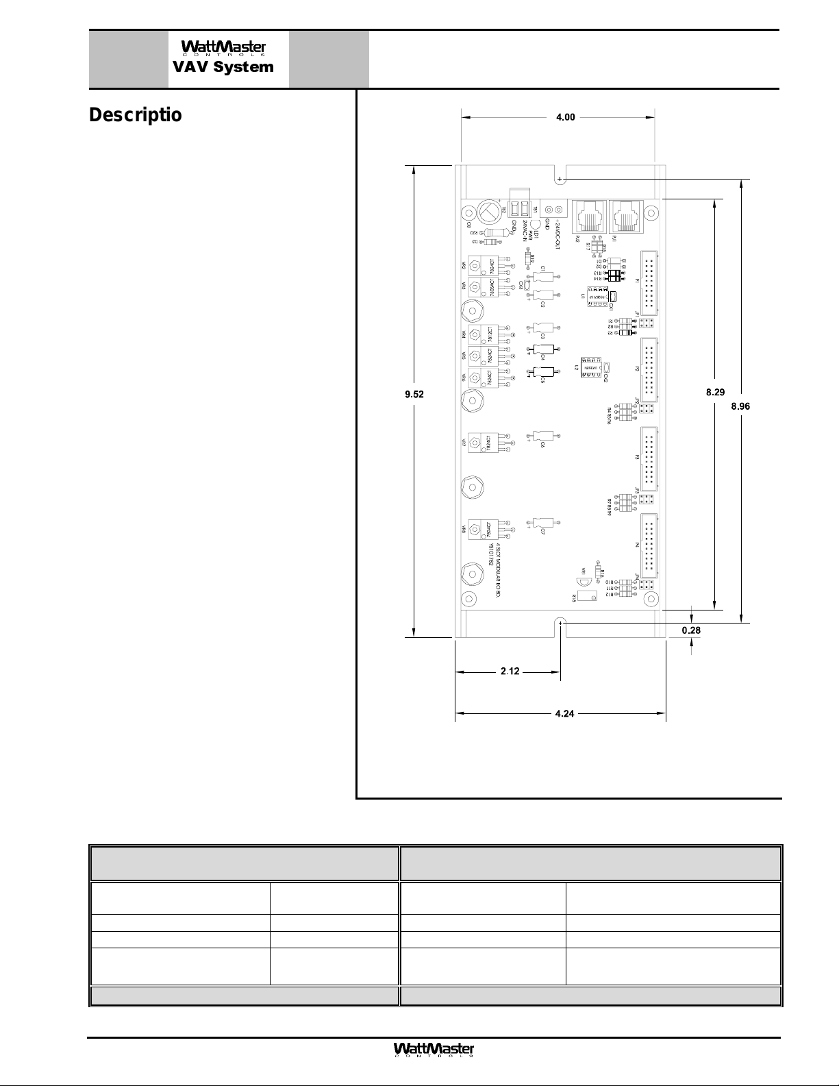
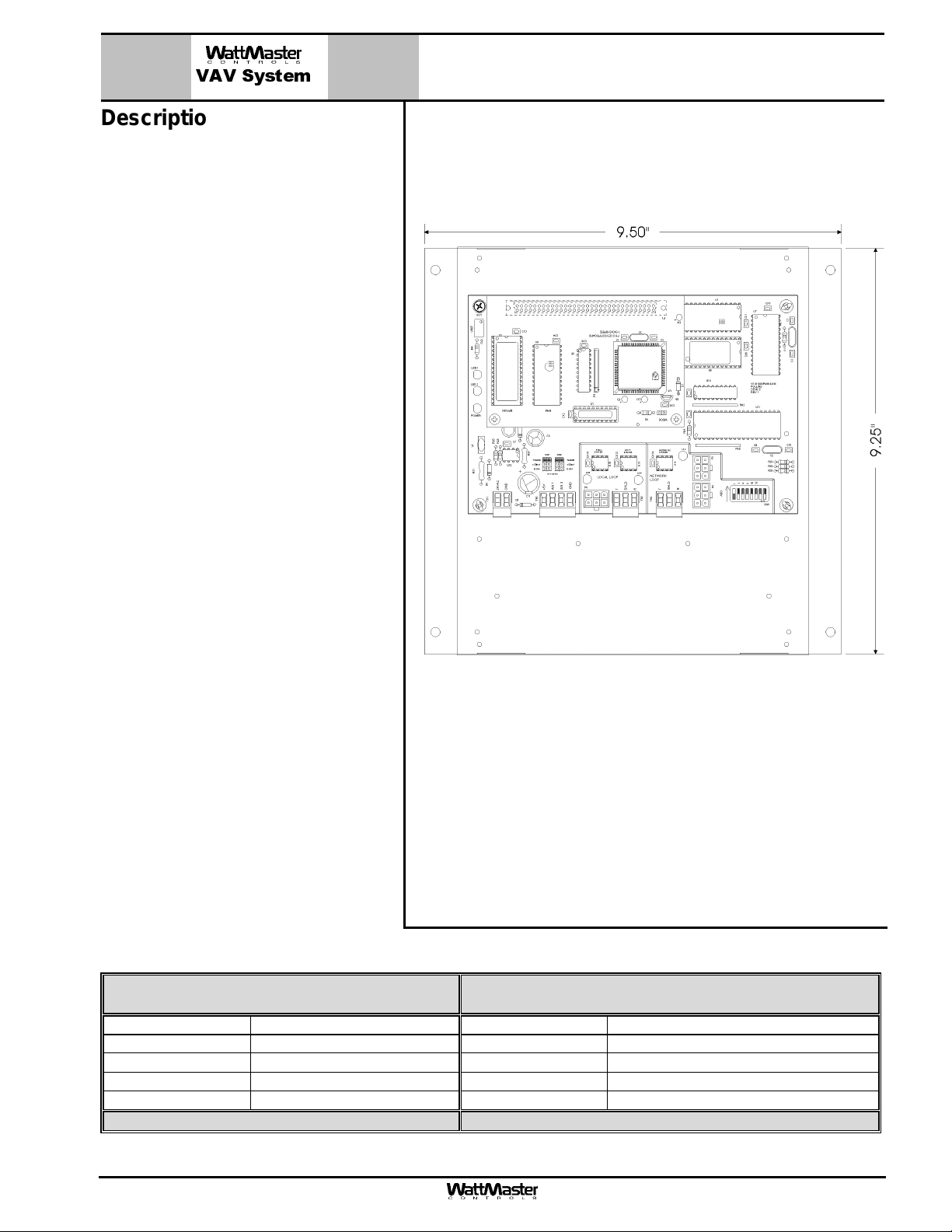
The VAV/CAV Controller Board is designed with
7 usable analog inputs, 2 analog outputs and 5
relay outputs. The controllers input and output
capabilities can be expanded by use of either 2
slot or 4 slot expansion boards that plug into the
WMVAV Controller by means of a modular cable.
The WMVAV Controller can be configured for
control of VAV Units (with or without VAVBOX
Controllers), Constant Volume Units and Air to Air
Heat Pump Units. Features include the following:
• Up to 8 Stages Each of Cooling and Heating
(4 on board, 12 more with expansion boards)
• Selectable Control Sensor
• Fan Proving Interlock
• Wetbulb Control of Economizer Operation
• Accepts Remote Occupied Signal
• Relief Pressure Control
• De-Humidification Capable
• Full Economizer Control
.20 Dia.
Typ. of 4
7.3”
TB1
COMM
T
SHLD
R
LD6
COMM
LD7
PWR
LD8
LED1
LD9
LED2
R1
U7
INPUTS
+VDC
AIN1
AIN2
AIN3
AIN4
AIN5
GND
GND
AOUT1
AOUT2
AIN7
GND
PJ1
TB3
PRESSURE
SENSOR
C21
RN1
1
CX5
1
RN3
+VREF
TESTPOINT
RV1
VREFADJ
C10
EXPANSION
WMVAV Controlle
6.2“
CX1
U1
U5
RS-485
COMM
HH
C1
P1
5.11V
EWDOG
R28
ADDRESS
RN5
PU1
D6
PU2
D7
PU3
D8
PU4
D9
PU5
D11
PU7
D14
C12
D15
C17
C20
R26
PJ2
U3
CX2
U2
EPROM
RAM
TUC-5RPLUS
(1MEG)
YS101816REV. 2
U6
C2
PHILIPS
C3
ADD
1
2
4
8
16
CX10
32
TOKEN
NETWORK
U10
SW1
C11
X2
0-5
0-1
VDC
VDC
JP1
U13
R15
U12
CX14
C14
R19
U14
CX13
U15
C15
R22
R24
R25
CX15
D17
PJ3
T'STAT
6.7”
D1
CX3
CX4
U4
RLY1
RLY2
PAL
1
RLY3
RN2
RLY4
CX6
X1
RLY5
1
RN4
U9
C7
R7
D10
L1
CX12
D12
R13
SC1
D19
D18
C19
C18
VR1
VR2
V1
D2D3D4D5
V2
V3
COM1-3
R1
R2
R3
R4
R5
COM4-5
TB2
V4
V5
U8
NE5090NPB3192
0PS
CX8
R6
C9
R10
D13
9936
R11
U11
MC34064A
C13
C16
TB4
GND
R27
D16
V6
POWER
7824CT
24VAC
M
6.6”
1.1”
• I.A.Q. Control with C0
Sensor Monitoring • Internal Trend Logging
2
• 7 Day, 2 Event per Day Scheduler Built In • 14 Day Holiday Scheduler Built In
• Optimal Start Scheduling Built In • Override from Occupied to Unoccupied Mode
• Supply Air Reset Capability
• Accepts Remote HVAC Mode Selection
Most HVAC unit applications can be configured with the standard WMVAV Controller. If the application requires more inputs
and/or outputs, optional relay expansion boards are available from the factory to provide for additional analog, binary or digital inputs and outputs as required. These expansion boards are installed on either a 2 slot or 4 slot expansion base board
that connects to the WMVAV Controller board via a modular cable connection.
Mounting – Factory Installed
If purchased separately the WMVAV Controller is provided with an integral backplate and can be mounted in the HVAC unit
control panel or remotely located and wired to the HVAC unit.
Technical Data MG331-21-VAV Controller
Power 24 Volt AC Weight 1.5 lb.
Power Consumption 8 VA Maximum Network Connection RS-485
Operating Temp
10°F to 149°F
Operating Humidity 90% RH Non-Condensing Communications RS-485 - 9600 Baud
Inputs: Outputs:
Room Temperature Type III-10kohm sensor (1) Fan-ON/OFF
Supply Air Temperature Type III-10kohm sensor
Outside Air Temperature Type III-10kohm sensor
Static Pressure Sensor 0-5VDC
Humidity Sensor 4-20Ma
Remote Occupied Signal Binary Contact Economizer Analog Output 0-10 VDC
Fan Proof Of Flow Binary Contact VFD, Bypass or Inlet Vane
Three Year Warranty WattMaster reserves the right to change specifications without notice
Form: WMS-MG331-21-VAV-WMVAVController-01D.doc Page 1 of 1
Protocol HSI Open Protocol Token Passing
(5) Relays - (2 Amp @ 24 VAC)
(4) User Configurable For :
Heating Or Cooling
Stages, Reversing Valve,
Warm-up Mode Box Command, Hot Gas Reheat
Control, Relief Fan Interlock, Preheat Coil
Analog Output 0-10 VDC
Control
Page 2
MG320-00-VAV
V
r
VAV System
Description
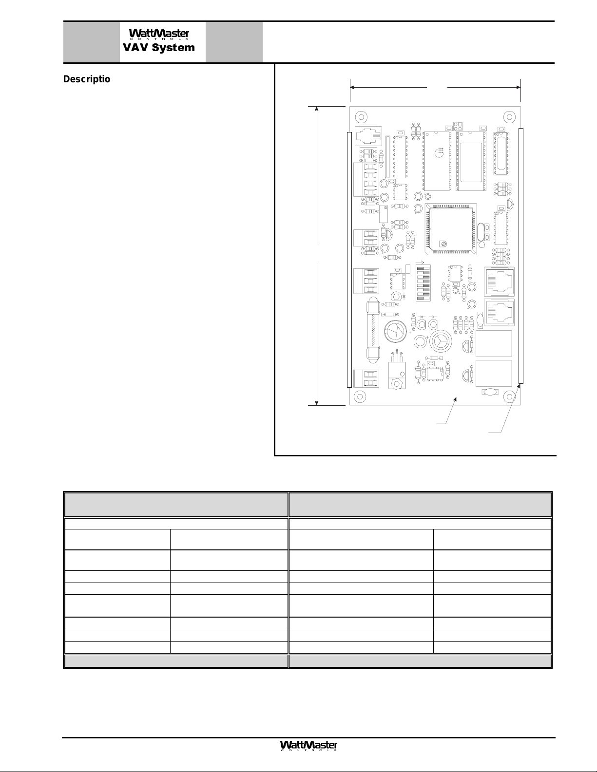
The MG320-00-VAV VAVBOX controller is used for
controlling airflow and operation of VAV terminal
units. It is a programmable digital controller, which
allows for program setpoints to be stored in nonvolatile memory. The controller is connected to a
room sensor via a modular cable assembly, which
monitors space temperature allowing the VAVBOX
controller to modulate a damper in response to
space temperature, duct temperature and airflow
requirements in the controlled space.
The MG320-00-VAV VAVBOX Controller has three
integral modular jacks for connection to the actuator, airflow sensor (for pressure independent applications) and relay or analog expansion boards, via
modular cables. A 2 wire terminal block is provided
for connection of a 24VDC power transformer, a 2
wire terminal block is provided for the Room Temperature Sensor and a 3 wire terminal block is provided for connection of the communications loop.
The controller has an on-board dip switch provided
for board addressing.
The VAVBOX controller is provided with two relays
for tri-state control of the damper actuator. The
actuator connects via a modular cable to the board
and provides the VAVBOX controller with feedback
monitoring for precise positioning of the actuator.
Mounting
Each VAVBOX controller is provided with a plastic
snap track modular mounting base. The snap track
is designed to be mounted with sheet metal screws
to a flat surface using the pre-punched mounting
slots provided. The VAVBOX controller is then
snapped into place on the snap track providing for
easy field mounting and servicing.
7.00"
AVBOX Controlle
FLOW
CX8
U8
RN1
1
B31920PS
74HC573N
D5
R27
CX9
C13
LMC662
C14
D5
R32
T'STA
T
F1
562
YS101
REV. 2
24VAC
GND
Zone Controller Board
R22
ADJ
VREF
P.U .
R23
R28
R24
U11
C11
R20
C15
EWDOG
R25
D7
CX10
COMM
75176
U10
LD3
POWER
R26
250
D4
MDL
VR1
T
7824
7824C
M
4.00"
U4
MS6264L-70PC
9936
RAM
C8
ADD
1
2
4
8
16
32
TOKEN
NET
LD2
LD1
REC
C7
9936
CX4
80C55
2
PHILIPS
PHILIPS
U5
U6
R14
D3
64A
MC340
U7
RAM
8K
32K
EPROM
PCB80C552-5-16WP
500650=1/3
DFD9940SM
93C46
CX6
C5
R100
R13
R12C6R11
Q2
R15
Q3
U3
V4.00F C094
AZZONE
R8
C3
C4
V1
R9
R10
fTimes New
fTimes New
Roman|b0|i0|
Roman|b0|i0|c0|p18;
c0|p18;OMRON
G5L-114P-PS
24VDC
CONTACT:
UL / CSA 5A250VAC
K1
D1
fTimes New
fTimes New
Roman|b0|i0|
Roman|b0|i0|c0|p18;
c0|p18;OMRON
G5L-114P-PS
24VDC
CONTACT:
D2
UL / CSA 5A250VAC
K2
CX3
CX1
U1
TCU32K2V
16L8
R1
R2
R3
CX2
X1
CX5
PJ1
PJ2
V2
Q1
B31920PS
74HC259
U2
C2C1
R4
R5
R6
R7
SION
EXPAN
TOR
ACTUA
R34
R18
U9
C9
C10
R19
ADDRE
SS
SW1
R21
SCAN
L1
R16
R17
Snap Track
Technical Data MG320-00-VAV
VAVBOX Controller
Specifications: Inputs:
Supply Power 24 Volt AC/DC Room Temperature Sensor Type III-10kohm Sensor
Power Consumption 4 VA Maximum Air Flow Sensor
(PI Applications Only)
Operating Temperature
35°F to 125°F
Power Wire Terminals
0-5” H2O Velocity Pressure
Modular Cable Connection
Operating Humidity 90% RH Non-Condensing Communications Wire Terminal s
Memory EEPROM Duct Temperature Sensor Type III-10kohm Sensor
Communications RS-485 - 9600 Baud
Outputs:
Mounting Method Snap Track Actuator Modular Cable Connection
Addressing Rocker Type Dip Switch Expansion Boards- Digital or Analog Modular Cable Connection
Three Year Warranty WattMaster reserves the right to change specifications without notice
Form: WMS-MG320-VAVBOXController-1C.doc Page 1 of 1
Wire Termi nal s
Wire Termi nal s
Page 3
VAV System
Description
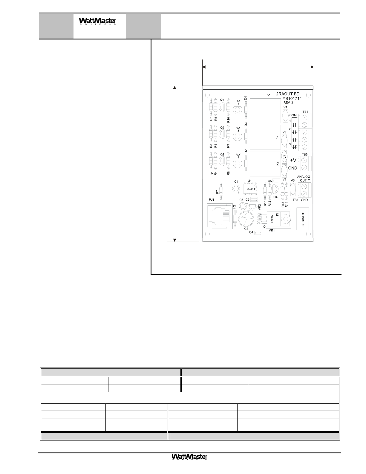
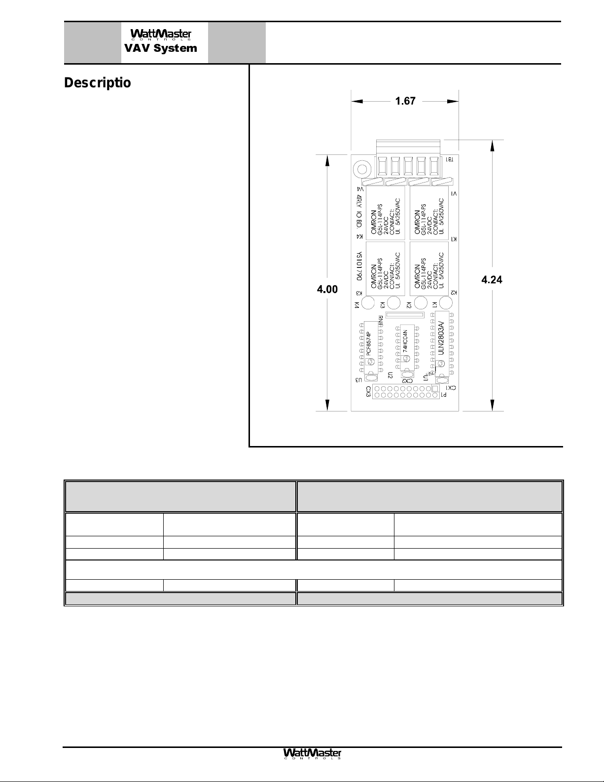
The OE322 - 3 Relay with Analog Output Expansion board is used in conjunction with the MG320–00-VAVZ controller board to allow for control of VAV
terminal units, including series and parallel fan terminal units with up to 3
stages of electric heat, SCR electric
heat or with modulating hot water heat.
The OE322 Analog Output Expansion
board provides 3 relay outputs for pilot
duty switching control, and 1 Analog
output for control of a 0-10V modulating
hot water valve or SCR controlled electric heating coil. The expansion board is
also equipped with 24 VDC (+V and
GND) output terminals for powering a
24 VDC hot water valve actuator if desired. A 24 VAC hot water valve actuator can also be used but will require the
use of a separate field supplied 24 VAC
transformer to power the valve actuator.
The OE322 - 3 Relay W/ Analog Output
Expansion board connects to the
MG320–00-VAVZ controller board by
means of a modular cable provided with
the OE322 board. Power is supplied to
the board by means of this modular cable. Screw terminals are provided for
connection of field wiring to the relay
and analog outputs.
The relay outputs are N.O. contacts with one common terminal. All outputs and the relay common are electrically
isolated from all other circuitry on the board. All relay outputs are supplied with transient suppression devices
across each set of contacts to reduce EMI and arcing. The relay output contacts are rated for pilot duty control of
a maximum of 2 Amps @ 24 VAC or 24 VDC. The analog output provides a 0 – 10 VDC modulating signal output
into a 1k Ohm minimum load. The 24 VDC (+V and GND) output terminals are rated for control of a 24 VDC
valve actuator with a maximum load rating of 12 Watts or less.
OE322 - 3 Relay W/ Analog Output
Expansion Board
3.00"
4.18"
Mounting
The OE322 - 3 Relay W/ Analog Output Expansion Board is supplied mounted on a plastic Snap Track channel.
The Snap Track channel has two mounting holes which are used to field mount the board with the provided
screws. The board should be mounted in close proximity to the MG320–00-VAV controller board to allow for connection of the modular cable.
Technical Data OE322- 3 Relay W/ Analog Output Expansion board
Operating Temp
Weight 4 oz Connection to Controller: Modular Cable
Analog Output Qty. 1 Analog Output Rating 0-10 VDC @ 1k Ohm minimum load
Relay Output Qty. 3 – Electrically Isolated Relay Contact Rating 2 Amp @ 24 VAC
Valve Actuator Power
Terminals Voltage
Three Year Warranty
Form: WMS-OE322-3Relay-1AnOutExpBrd-1C.doc Page 1 of 1
10°F to 149°F
24 VDC 24 VDC Valve Actuator
Operating Humidity 90% RH Non-Condensing
Outputs:
12 Watts
Maximum Load
WattMaster reserves the right to change specifications without notice
Page 4
VAV System
Description
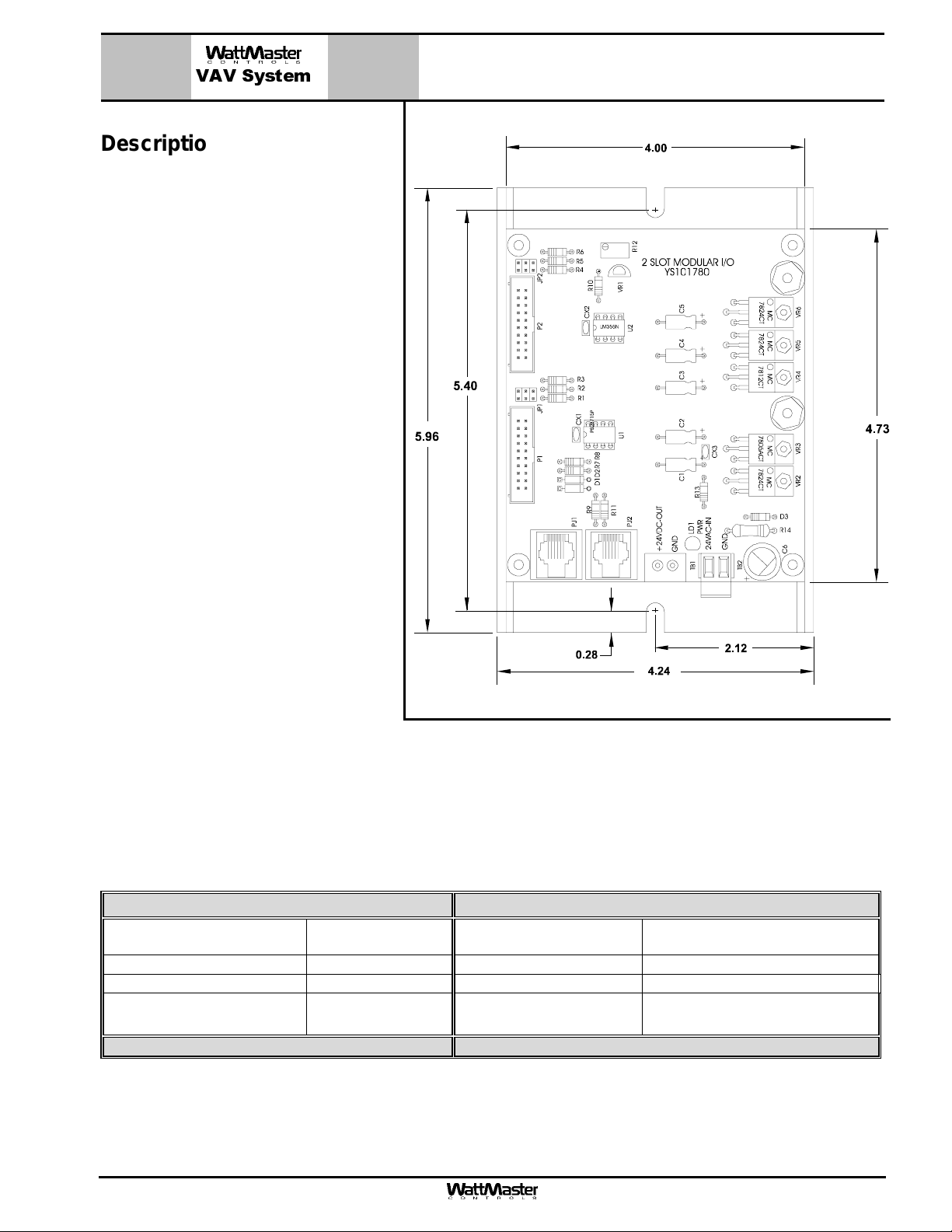
The OE352 – 2 Slot Modular I/O Base
Board is used in conjunction with the following Modular Expansion Boards:
• O354 – 4 Analog Input &
1 Analog Output
• OE355 – 4 Analog Output
• OE356 – 4 Digital Inputs
• OE357 – 4 Relay Outputs
For easy wiring the OE352 – 2 Slot
Modular I/O Base Board provides for up
to (2) of the above expansion boards to
be connected to it by means of an integral
male/female push-in connector arrangement. Power is supplied to the Expans ion
Boards through this connector, simplifying
installation and connection. Jumpers are
also provided on the OE352 Modular I/O
Base Board for addressing and configuration of the Modular Expansion Board(s).
OE352 – 2 Slot
Modular I/O Base Board
Any combination of Modular Expansion
Boards may be connected to the OE352
Modular I/O Base Board to provide the
input/output capabilities required.
The main controller software used with
the OE352 Modular I/O Base determ ines
which Modular Expansion Boards m ay be
used.
Mounting
The OE352 – 2 Slot Modular I/O Base Board is supplied m ounted on a plastic Snap Track channel. T he Snap
Track channel has two mounting holes, which are used to field mount the board with the provided screws. The
board should be mounted in close proximity to the MG331-21-VAV HVAC Unit Controller board to allow for connection of the modular cable.
Technical Data
Operating
Power
Operating Temp
Communications Integral I2 C Chip Weight 8 oz.
Qty of Slots Provided For
Modular Expansion Boards
Three Year Warranty WattMaster reserves the right to change specifications without notice
24 VAC Power Consumption 5 VA Maximum
10°F to 149°F
Operating Humidity 90% RH Non-Condensing
Mounting Provisions Supplied with
2
OE352 – 2 Slot Modular I/O Base Board
Snap Track Base
Form: WMS-OE3522SlotBaseBoard-1B.doc Page 1 of 1
Page 5
VAV System
Description
The OE353 – 4 Slot Modular I/O Base
Board is used in conjunction with the following Modular Expansion Boards:
• O354 – 4 Analog Input &
1 Analog Output
• OE355 – 4 Analog Output
• OE356 – 4 Digital Inputs
• OE357 – 4 Relay Outputs
For easy wiring the OE353 – 4 Slot
Modular I/O Base Board provides for up
to (4) of the above expansion boards to
be connected to it by means of an integral
male/female push-in connector arrangement. Power is supplied to the Expans ion
Boards through this connector, simplifying
installation and connection. Jumpers are
also provided on the OE353 Modular I/O
Base Board for addressing and configuration of the Modular Expansion Board(s).
OE353 – 4 Slot
Modular I/O Base Board
Any combination of Modular Expansion
Boards may be connected to the OE353
Modular I/O Base Board to provide the
input/output capabilities required.
The main controller software used with
the OE353 Modular I/O Base determ ines
which Modular Expansion Boards m ay be
used.
Mounting
The OE353 – 4 Slot Modular I/O Base
Board is supplied mounted on a plastic
Snap Track channel. The Snap Track
channel has two mounting holes, which
are used to field mount the board with the
provided screws. The board should be
mounted in close proximity to the MG33121-VAV HVAC Unit Controller board to
allow for connection of the modular cable.
Technical Data OE353 – 4 Slot
Modular I/O Base Board
Operating
Power
Operating Temp
Communications Integral I2 C Chip Weight 8 oz.
Qty of Slots Provided For
Modular Expansion Boards
Three Year Warranty
24 VAC Power Consumption 5 VA Maximum
10°F to 149°F
Operating Humidity 90% RH Non-Condensing
Mounting Provisions Supplied with
4
WattMaster reserves the right to change specifications without notice
Snap Track Base
Form: WMS-OE353-4SlotBaseBoard-1B.doc Page 1 of 1
Page 6
OE354 – 4 Analog Input/1 Analog
VAV System
Description
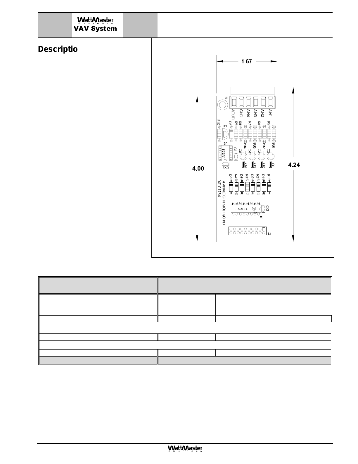
The OE354 - 4 Analog Input/1 Analog
Output Modular Expansion Board is us ed
in conjunction with the OE352 - 2 Slot
Modular I/O Base Board or the OE353 - 4
Slot Modular I/O Base Board. The OE354
Expansion Board provides 4 analog inputs and 1 analog output.
For easy wiring the OE354 – 4 Analog
Input/1 Analog Output Modular Expansion
Board connects to the OE352 or OE353
Modular I/O Base Boards by means of an
integral connector arrangem ent. Power is
supplied to the OE354 - Expansion Board
through this connector, sim plifying installation and connection. Jumpers are provided on the OE352 and OE353 Modular
I/O Base Boards for addressing of the
OE354 - Expansion Board(s).
The analog inputs have removable pullup resistors associated with each input,
which can be used for connection of
thermistor type sensors or dry contact
closure configuration. The pull-up resistors are removed when a voltage signal is
to be used. Jumpers are pr ovided to configure the inputs for either 0-5 Volt or 0-10
Volt operation. Input and output resolution
is 0.4% or (0.04 Volts).
Output Modular Expansion Board
Technical Data OE354 – 4 Analog Input/1 Analog Output
Modular Expansion Board
Operating
Power
Operating Temp
Communications Integral I2 C Chip Weight 4 oz.
From OE352/OE353
Modular I/O Board
10°F to 149°F
Power Consumption 2 VA Maximum
Operating Humidity 90% RH Non-Condensing
Inputs:
Analog Input Qty. 4 Analog Input Types 10K Thermistor, Dry Contact, 0-10 or 0-5 Volt
Output:
Analog Output Qty. 1 Analog Output Rating 0-10 VDC @ 1K Ohm
Three Year Warranty WattMaster reserves the right to change specifications without notice
Form: WMS-OE354-4AI-1AO-ModExpBoard-1B.doc Page 1 of 1
Page 7
OE355 – 4 Analog Output
VAV System
Description
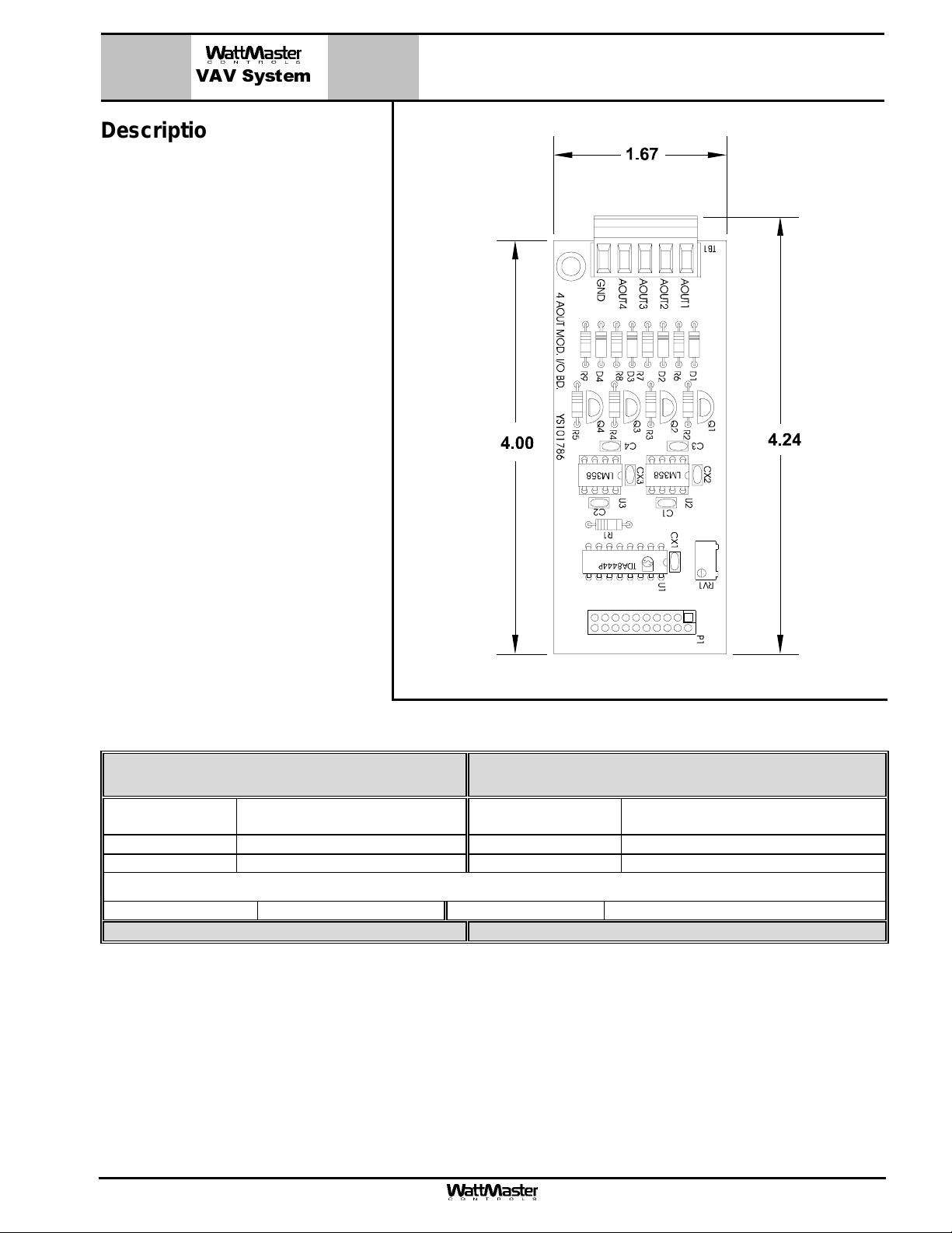
The OE355 - 4 Analog Output Modular
Expansion Board is used in conjunc tion
with the OE352 - 2 Slot Modular I/O
Base Board or the OE353 - 4 Slot
Modular I/O Base Board. The OE355
Expansion Board provides (4) 0-10 VDC
analog outputs for driving actuators,
valves etc.
For easy wiring the OE355 – 4 Analog
Output Modular Expansion Board connects to the OE352 or OE353 Modular
I/O Base Boards by means of an integral connector arrangement. Power is
supplied to the OE355 - Expansion
Board through this connector, simplifying installation and connection. Jumpers
are also provided on the OE352 and
OE353 Modular I/O Base Boards for
addressing of the OE355 - Expansion
Board(s).
Modular Expansion Board
The analog outputs are designed to
drive a 1K Ohm minim um load. All outputs have a resolution of 1.6% or (.16
Volts).
Technical Data
Operating
Power
Operating Temp
Communications Integral I2 C Chip Weight 4 oz
Analog Output Qty. 4 Analog Output Rating 0-10 VDC @ 1K Ohm
Three Year Warranty WattMaster reserves the right to change specifications without notice
From OE352/OE353
Modular I/O Board
10°F to 149°F
Power Consumption 2 VA Maximum
Operating Humidity 90% RH Non-Condensing
Outputs:
OE355 – 4 Analog Output
Modular Expansion Board
Form: WMS-OE355-4AO-ModExpBoard-1B.doc Page 1 of 1
Page 8
VAV System
Description
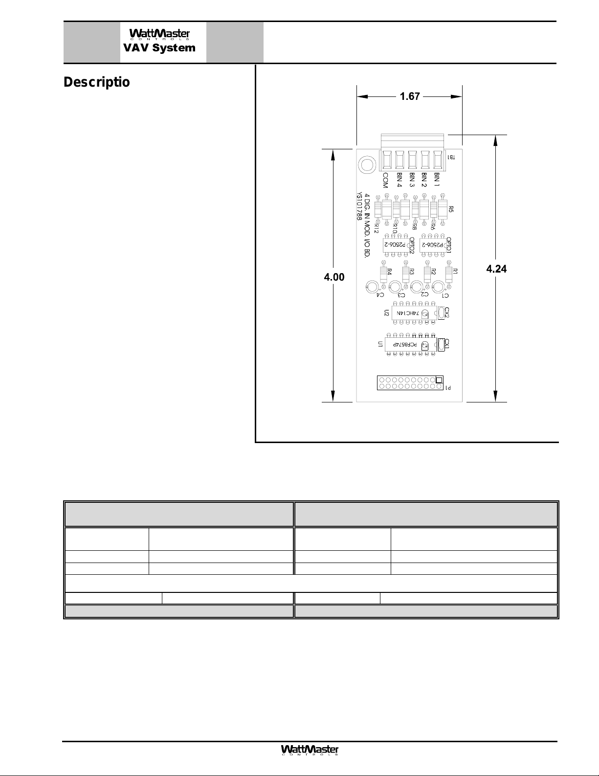
The OE356 - 4 Digital Input Modular Ex pansion Board is used in conjunction with
the OE352 - 2 Slot Modular I/O Base
Board or the OE353 - 4 Slot Modular I/O
Base Board. The OE356 Expansion
Board provides 4 digital inputs f or s ensing
status of connected dry contact closures
or connected voltage depending on how
the external equipment is wired to the
digital inputs on the OE356 board.
For easy wiring the OE356 – 4 Digital Input Modular Expansion Board connects to
the OE352 or OE353 Modular I/O Base
Boards by means of an integral connector
arrangement. Power is supplied to the
OE356 - Expansion Board through this
connector, simplifying installation and
connection. Jumpers ar e also provided on
the OE352 and OE353 Modular I/O Base
Boards for addressing of the OE356 - Expansion Board(s).
OE356 - 4 Digital Input
Modular Expansion Board
The digital inputs on the OE356 share one
common terminal between the 4 inputs.
The comm on terminal may be connected
to either 24 VAC or the 24 VAC com mon
depending on how the board is to be
wired to the equipment. Inputs are optically isolated from other circuitry.
Technical Data OE356 – 4 Digital Input
Modular Expansion Board
Operating
Power
Operating Temp
Communications Integral I2 C Chip Weight 4 oz.
Digital Input Qty. 4 Digital Input Rating 24 VAC or Dry Contact Closure
Three Year Warranty WattMaster reserves the right to change specifications without notice
From OE352/OE353
Modular I/O Board
10°F to 149°F
Power Consumption 2 VA Maximum
Operating Humidity 90% RH Non-Condensing
Inputs:
Form: WMS-OE356-DigitalInput-ModExpBoard-1B.doc Page 1 of 1
Page 9
VAV System
Description
The OE357 - 4 Relay Output Modular
Expansion Board is used in conjunc tion
with the OE352 - 2 Slot Modular I/O
Base Board or the OE353 - 4 Slot
Modular I/O Base Board. The OE357
Expansion Board provides 4 relay outputs for pilot duty switching control.
For easy wiring the OE357 – 4 Relay
Output Modular Expansion Board connects to the OE352 or OE353 Modular
I/O Base Boards by means of an integral connector arrangement. Power is
supplied to the OE357 - Expansion
Board through this connector, simplifying installation and connection. Jumpers
are also provided on the OE352 and
OE353 Modular I/O Base Boards for
addressing of the OE357 - Expansion
Board(s).
OE357 - 4 Relay Output
Modular Expansion Board
The relay outputs are N.O. contacts with
one common terminal. All outputs and
the relay common are electrically isolated from all other circuitry on the
board. All relay outputs are supplied
with transient suppression devices
across each set of contacts to reduce
EMI and arcing. The relay output contacts are rated for pilot duty control at a
maximum of 2 Amps @ 24 VAC or 24
VDC.
Technical Data OE357 – 4 Relay Output
Modular Expansion Board
Operating
Power
Operating Temp
Communications Integral I2 C Chip Weight 4 oz
From OE352/OE353
Modular I/O Board
10°F to 149°F
Power Consumption 2 VA Maximum
Operating Humidity 90% RH Non-Condensing
Outputs:
Relay Qty. 4 Relay Contact Rating 2 Amps @ 24 VAC
Three Year Warranty WattMaster reserves the right to change specifications without notice
Form: WMS-OE357-4RelayOutput-ModExpBoard-1B.doc Page 1 of 1
Page 10
VAV System
Description
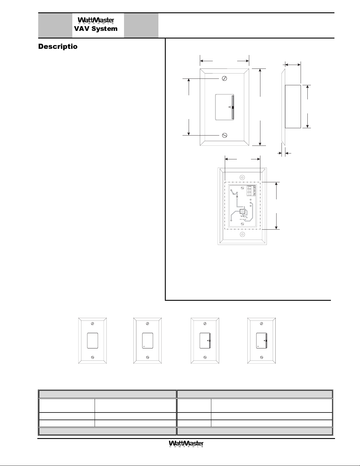
The patented design, OE21x series Standard
Room Sensor provides accurate sensing of
the room temperature. Its design allows for
flush wall mounting yet rejects the influence of
surface and internal wall temperatures. The
Standard Room Sensor is used in conjunction
with the WMVAV and the VAVBOX controllers.
Wire terminals are provided on the sensor for
connection to the controllers.
The Room Sensor’s attractive styling and off
white casing color make it suitable for most
building decors. If interior decoration requires,
the Room Sensor casing can also be painted
or wall papered without affecting the sensor's
performance. Room Sensors are available in 4
different configurations:
• OE210 Sensor Plain
• OE211 Sensor with Override
• OE212 Sensor with Setpoint
Adjustment
• OE213 Sensor with Setpoint
Adjustment and Override
3.25“
OE210, 211, 212 & 213
Standard Room Sensors
2.75“
W
A
R
M
E
R
C
O
O
L
E
R
2.00“
TMP
GND
AUX
OUT
4.50“
0.88“
0.25“
2.50"
Wall Cut-Out Dimensions
When Sensor Is To Be
Mounted Without
2.75“
Handy Box (By Others)
Modular cable from the W MVAV or VAVBOX
controllers to the Modular Room Sensor
should not be run in conduit with other AC line
voltage wiring, or with any conductors carrying
highly inductive loads.
Mounting
The Room Sensors are designed to be
mounted on a vertical, 2” x 4” electrical box
recessed in the wall. If the wall cannot be
penetrated, a plastic surface mount box such
as those made by Wiremold™, may be used to
mount the sensor to the wall surface.
W W
A A
R R
M M
E E
R R
C C
O O
OVR OVR
OE210 OE211
Room Sensor - Plain
Room Sensor
With Override
Technical Data OE210, OE211, OE212, OE213 Standard Room Sensor
Sensor Element Type III Thermistor
10k ohm @ 77º F
Accuracy
±0.4º F between 40º F to 95º F
Range -30º F to 150º F Weight 4 oz.
3 Year Warranty WattMaster reserves the right to change specifications without notice
Mounting Designed to be Flush Mounted to Wall
Line Loss 0.25º F max. error, using 22 AWG wire at 1000 ft
O O
L L
E E
R R
OE212
Room Sensor
With Setpoint Adjust
using Vertical 2” x 4” Handy Box (by others)
OE213
Room Sensor
With Setpoint Adjust
& Overide
Form: WMS-StandardRoomSensor-1B.doc Page 1 of 1
Page 11
MG392-05
r
VAV System
Description
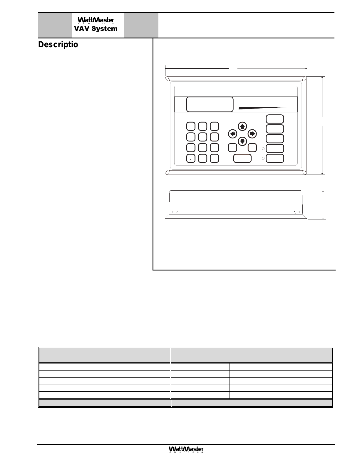
The MG392-05 Modular System Manager
provides a direct link to enable the system
operator to view the status and to adjust
the setpoints of any controller on the control system communications loop. The
Modular System Manager is designed to
be used with the WattMaster VAV Control
System. The System Manager is housed
in an attractive beige colored plastic enclosure. The System Manager is
equipped with a four line by 20 character
backlighted display panel and a 24 key
membrane k eypad for data selection and
entry. All keypad operations are simple
and straight forward, utilizing non-cryptic
plain English language messages. Menu
driven programm ing allows for eas y setup
and operation without the need for specialized training. The System Manager
also has 2 integral LED’s for user notification of system alarm conditions and
override initiations. Protection from unauthorized users is provided by the System Manager’s integral multi-level passcode authorization programming.
Modular System Manage
9.00"
System Manager
STATUS
SETPOINTS
NEXT
SCHEDULES
OVERRIDES
ALARMS
13
2
MINUS
-
PREV
6
ESC
9
4
708
DEC
5
DOWN
ENTER
UP
CLEAR
6.25"
1.81"
The Modular System Manager is connected to the communic ations and power
loop of the system via modular cables
that simply plug into the System Manager
board and are pigtailed into 6 individual
wires on the other end for hard wiring into
a 24 VAC transformer (by others) the local communications wiring loop.
Mounting
The Modular System Manager is designed f or wall mounting. Mounting holes are provided to attach the Modular
System Manager to a standard handy box. It is recomm ended that the System Manager be m ounted at approximately eye level to allow for ease of programming and r eading of the display. The System Manager is typically
mounted in the building manager or s uperintendent’s office or in an equipm ent room. The attractive enclosure is
quite suitable for mounting in any location or with most decors.
Technical Data MGOE392-05
Modular System Manager
Power 24 Volt AC/DC Display 4 Line by 20 Character Backlighted LCD
Power Consumption 5 VA Maximum Network Connection RS-485
Operating Temp
10°F to 149°F
Operating Humidity 90% RH Non-Condensing Housing Material Beige Plastic
Keypad 24 Key Membrane Type Communications RS-485 - 9600 Baud
3 Year Warranty WattMaster reserves the right to change specifications without notice
Protocol HSI Open Protocol Token Passing
Form: WMS-MG392-05-ModularSystemManager-1C.doc Page 1 of 1
Page 12
VAV System
Description
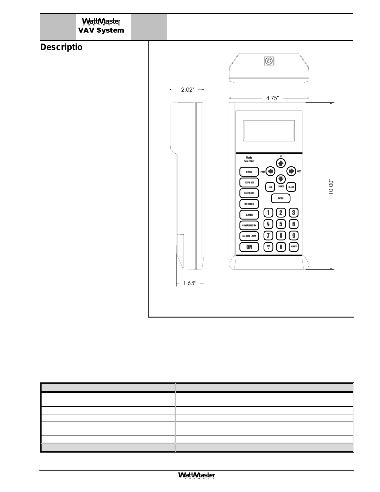
The MG391-05 Modular Service Tool
is a system interface that provides a
direct link to enable the system operator to view the status, configure
and to adjust the setpoints of any
controller on the control system
communications loop. The Modular
Service Tool is housed in an attractive beige colored plastic enclosure.
The display area is covered with a
clear plastic bezel for protection of
the display screen. The Modular
Service Tool has a four line by 20
character display panel with adjustable contrast control and a 27 key
membrane keypad for data selection
and entry. All keypad operations are
simple and straight forward, utilizing
non-cryptic plain English language
messages. Menu driven programming allows for easy setup and operation without the need for specialized training. The MG391-05 Modular Service Tool is supplied with (4)
AA (1.5V) Volt alkaline battery, a 120
VAC/5 VDC power supply and a
communication cable terminated
with an 8 pin DIN connector for connection to the Service Tool. The cable allows the user to setup and program any controller equipped with a
8 pin DIN connector to be programmed by simply plugging the
quick connect terminal into the
socket on the controller. A PL101904
Modular Service Tool Adapter is also
provided for use on controllers that
do not have 8 pin DIN connectors on
their circuit board.
2.02"
1.63"
MG391-05
Modular Service Tool
4.75”
Mode
Selection
”
0
0
.
0
1
13
2
654
708
9
-
The Modular Service Tool is designed to be carried by the system installer or service technician. Its rugged plastic
housing, provides superior protection for the electronic components housed inside. The OE391-054 Modular
Service Tool is a top quality service tool that will stand up to the demands of the typical job site environment for
many years.
Technical Data MGE391-05 Modular Service Tool
Power (4) AA (1.5V) Batteries
Supplied
Power Switch Membrane Switch Network Connection RS-485
Operating Temp
Operating Humid-
ity
Keypad 27 Key Membrane Style Communications RS-485 9600 Baud
3 Year Warranty WattMaster reserves the right to change specifications without notice
Form: WMS-MG391-05-ModularServiceTool-1C.doc Page 1 of 1
90% RH Non-Condensing Color Beige
10°F to 149°F
Display 4 Line by 20 Character
Protocol HSI Open Protocol Token Passing
Page 13
MG364-22– MiniLink
VAV System
Description
The MG364-22 MiniLink Polling Device is
a network controller that is used to integrate multiple local communication loops
into a network communications system.
“Network” loop terminals on the MiniLink
Polling Device are designed to be connected to the CommLink II and to other
MiniLink Polling Devices on the ”Network”
communications loop. “Local” loop terminals are designed to be connected to
controllers installed on the “Local” communications loop.
The MiniLink Polling Device is provided
with a 2 wire terminal block for connection
to the required 24 VAC source(by others).
It also has (2) 3 wire terminal blocks for
communications wiring. One of the terminal blocks is field connected to the “Local”
communications loop and the other is
field connected to the “Network” communications loop.
Polling Device
The MiniLink Polling Device utilizes token
passing communication architecture. The
MiniLink Polling Device is designed to
serve as the local communications loop
master. This means that it is responsible
for sending the token to all the controllers
on the local communications loop. Network communications are of the RS-485
type operating at 19,200 baud. Local
communications are also of the RS-485
type and operate at on systems requiring
override or alarm indication. It also provides tenant-logging capabilities for the
WattMaster VAV system.
MiniLink Polling Device Is Supplied Factory Mounted To
Control Enclosure. Cover Shown Removed For Clarity
Mounting
The MiniLink Polling Device is factory
mounted in a galvanized sheet metal enclosure. Mounting holes are provided in
the enclosure for surface mounting.
Technical Data MGE364-22 – MiniLink
Polling Device
Power 24 Volt AC System Connection Molex® Connectors & Terminals
Power Consumption 6VA Maximum Network Connection RS-485
Operating Temp
Operating Humidity 90% RH Non-Condensing Housing Material 22 Ga. Galvanized Steel
Communications RS-485 - 9600 Baud, Local Communications RS-485 - 19200 Baud, Network
3 Year Warranty WattMaster reserves the right to change specifications without notice
10°F to 149°F
Protocol HSI Open Protocol Token Passing
Form: WMS-MG364-22MiniLinkPollingDevice-1B.doc Page 1 of 1
Page 14
VAV System
Description
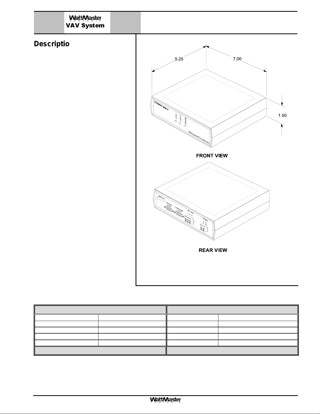
The OE361 - CommLink II Communications Interface allows user ac cess to any
controller connected to the controls system. The CommLink II comes packaged
in an attractive beige colored plastic enclosure. The Comm Link II is powered by
a small wall mounted plug-in transfor mer
that is included. Locally, an optional onsite computer may be connected to the
CommLink II for direct access to system
control parameters. Remote access is
obtained via an optional modem which is
connected with the CommLink II Communication Interface. With a modem installed, the CommLink II may be configured to call a number, if an alar m condition occurs. With the modem option the
system could be dialed and monitored
from a remote location by a PC. Computer and modem cables (6ft long) are
provided with the CommLink II.
OE361 – CommLink II
Communications Interface
Mounting
If an on-site computer is to be used for
direct connection and monitoring of the
system, the CommLink II should be located near the computer terminal to
monitor the system. If no on-site computer is to be used, locate the Comm Link
II near the phone line jack for ease of
connection to a modem. If for any reason
you use cables of greater length than
those provided with the CommLink II (6 ft.
long) be sure the cables that connect the
CommLink II to the modem and the
CommLink II to the on-site computer do
not exceed twenty-five feet in length.
Technical Data OE 361 - CommLink II Communication Interface
Power 24 Volt AC Computer Connection RS-232
Plug-in Transformer 110V to 24V (Included) Network Connection RS-485
Power Consumption 14 VA Maximum Protocol HSI Open Protocol Token Passing
Operating Temperature
Operating Humidity 90% RH Non-Condensing Communications RS-485 - 9600 Baud
Three Year Warranty WattMaster reserves the right to change specifications without notice
10°F to 140°F
Physical Connections (2) 9 Pin/DB9 Male
Form: WMS-OE361-CommLink-1B.doc Page 1 of 1
Page 15

1.50
7.00
REAR VIEW
FRONT VIEW
VAV System
Description
The OE361-08 CommLink III Communications Interface allows com puter access
into the WattMas ter VAV controls system
and also provides communications across
multiple local communications loops on
the control system.
The CommLink III comes pac kaged in an
attractive beige colored plastic enclos ure.
The Comm Link III is powered by a small
wall mounted plug-in transformer that is
included. Locally, an optional on-site Personal Computer with Prism software installed may be connected to the
CommLink III to provide direct access to
system control parameters by using the
supplied USB cable (6 ft. long).
Remote telephone access to the control
system can be obtained via the optional
OE419-05 Modem Kit which can be field
installed inside the CommLink III Communication Interface. With the optional
modem kit installed, the control system
can be accessed remotely by using a
Remote Link modem (purchased separately) connected to a Personal Computer
with Prism software installed at the remote location and dialing the phone number of the phone line the CommLink III
with modem kit is c onnected to. Also with
the modem k it installed the CommLink III
can be configured to call a pager or cell
phone number, if an alarm condition occurs. A USB cable (6ft long) is provided
with the CommLink III for connection to
your computer.
OE361-08 CommLink III
Communications Interface
5.25
Mounting
If an on-site c omputer is to be used for direct c onnection and monitoring of the system, the Comm Link III s hould
be located near the c omputer term inal to m onitor the system . If no on-site com puter is to be used and/or you are
installing the optional modem kit, locate the CommLink III near the phone line jack for ease of connection.
Technical Data OE361-08 CommLink III Communication Interface
Power 24 Volt AC Computer Connection USB Version 1.1 or 2.0
Plug-in Transformer 110V to 24V (Included) Network Connection RS-485
Power Consumption 14 VA Maximum Protocol HSI Open Protocol Token Passing
Operating Temperature
Operating Humidity 90% RH Non-Condensing Communications RS-485 - 9600 Baud
Three Year Warranty WattMaster reserves the right to change specifications without notice
Form: WMS-OE361-08-CommLinkIII-01A.doc Page 1 of 1
10°F to 140°F
Cabling Included (1) 6 Ft. Long USB Cable
Page 16

1.50
7.00
REAR VIEW
FRONT VIEW
VAV System
Description
The OE361-12 Comm Link IV Communications Interface allows com puter acc es s
into the WattMas ter VAV controls system
and also provides communications
across multiple local communications
loops on the control system.
The CommLink IV comes packaged in
an attractive beige colored plastic enclosure. The Com mLink IV is powered by a
small plug-in transf ormer that is included.
Locally, an optional on-site personal
computer with Prism software installed
may be connected to the CommLink IV
to provide direct access to system control parameters. A USB cable ( 6 ft. long)
is provided with the CommLink IV for
connection to your computer.
Remote telephone acces s to the control
system can be obtained by purchasing
the optional OE419-06 Remote Link II
modem. With the optional Rem ote Link II
modem installed, the c ontrol system can
be accessed remotely by using another
Remote Link II m odem (purchas ed separately) connected to a personal computer
with Prism software installed at the remote location. W ith the Remote Link installed at the job site, the Com mLink IV
can be configured to call a pager or cell
phone number if an alarm condition occurs.
OE361-12 CommLink IV
Communication Interface
5.25
An optional OE415-02 IP Module Kit is
also available that provides an Ethernet
connection to the controls system from
any computer connected to your building’s LAN. It can also be configured to
allow access to the control system from
the Internet if your Ethernet firewall is
configured for this option.
Mounting
If an on-site computer is to be used for direct c onnection and monitoring of the system, the CommLink IV should
be located near the c omputer term inal to m onitor the system . If no on-site com puter is to be used and/or you are
installing the Remote Link II option, locate the CommLink IV near the phone line jack for ease of connection.
Technical Data OE361-12 CommLink IV Communication Interface
Power 24 Volt AC *Remote Link II Conn. RS-232 Serial Port (9 pin)
Plug-in Transformer 120V to 24VAC (Included) **Ethernet Conn. RJ-45 Ethernet Port
Power Consumption 14 VA Maximum Network Loop RS-485 - 19,200 Baud
Operating Temperature
Operating Humidity 90% RH Non-Condensing Cabling Included (1) 6 Ft. Long USB Cable
Computer Conn. USB Version 1.1 or 2.0 Local Loop RS-485 - 9600 Baud
Three Year Warranty
* This Port Is Only Used With The Optional OE419-06 Remote Link II. ** This Port Is Only Used With The Optional OE415-02 IP Module Kit.
Form: WMS-CLKIV-SUB-01A-0907 Page 1 of 1
10°F to 140°F
Protocol HSI Open Protocol Token Passing
WattMaster reserves the right to change specifications without notice
Page 17

VAV System
OE366 USB-Link
Description
The OE366 USB-Link allows com puter access into
the WattMaster VAV controls system and also provides communications across multiple local communications loops on the control system when a
CommLink Communications Interface is installed
on the system.
The USB-Link provides a direct link to enable the
system operator to view the status and to configure
and adjust the setpoints of any controller on the
control system communications loop using the
Prism II computer front end software.
The USB-Link is small in size and is powered by
the USB port of the computer it is plugged into,
making it com pletely portable and allowing connection to the system from any controller.
The USB-Link is supplied with a USB cable, a miniDIN male com munication cable, and two mini-DIN
to terminal adapters. The communication cable
allows the user to walk up to any controller that has
a communication s ocket and plug in the USB-Link
to gain access to the system. The adapters are
used for boards that do not have a f emale mini-DIN
plug connection.
To use the USB-Link, you will need a computer
with an available USB 1.1 or 2.0 port with the included USB drivers installed. You will also need the
Prism II computer front end software installed on
the computer.
CAUTION: The USB-Link does not work with Prism
I software. It only works with Prism II.
Technical Data OE366 USB-Link
Operating Temperature
Operating Humidity 90% RH Non-Condensing Communications RS-485 - 9600 Baud
Computer Connection USB Version 1.1 or 2.0 Adapters Included PL1019054 and PL101905 Mini-DIN
Three Year Warranty
10°F to 140°F
Cabling Included (1) 6 Ft. Long USB Cable and
(1) 7 Ft. Long Communications Cable
Plug Adapters
WattMaster reserves the right to change specifications without notice
Form: WMS-OE366-USB-Link-01A.doc Page 1 of 1
Page 18

VAV System
w
w
Description
The OE419-04 Remote Link is essentially a 14,400 baud modem. The Remote Link is used f or achieving remote
communications with all WattMaster
VAV systems. Built in error correction
(V.42/mnp 2-4) and data compression
(V.42bis/mnp 5) will maximize data
transfer integrity and boost average
throughput up to 57.6 kbps. The Remote Link connects to the Com mLink II
communications interface at the Orion
control system location. A telephone line
connects the Remote Link to the local
phone service. By dialing the telephone
number that the Remote Link is connected to, (using a modem from a remote location) the Orion system can be
monitored and controlled using the
WattMaster Prism computer front end
software package.
OE419-04 Remote Link
1
4
5"
R
em
ote
Lin
k
SIG
DET
RDY
SND
REC
PWR
Front Vie
7"
1
2
1"
Mounting
The Remote Link should be mounted
close to a serviceable telephone outlet.
It connects via a serial data cable to the
CommLink II communications interface
and via a telephone cable to the telephone outlet jack. A molded cable for
connection from the CommLink to the
Remote Link is supplied with the
CommLink . If an on-site com puter is required, it should be connected to the
CommLink at or near the location where
the Remote Link is located. If for any
reason you use cables of greater length
than those provided with the CommLink
II (6 ft. long) be sure the cables that
connect the CommLink II to the Remote
Link and the Comm Link II to the on-site
computer do not exceed twenty-five feet
in length.
SERIAL #
TELCO
LINE
SERIAL DATA
POW
ER
Rear Vie
Technical Data
OE419-04 Remote Link
Power 9 Volt DC Computer Connection RS-232, 25 Pin DB25 Female
Plug-in Transformer 110V to 9V (Included) Phone Connection RJ-11 Female
Power Consumption 500mA Maximum Line Speed 14,400 bps
Operating Temperature
10°F to 140°F
Data Compression V.42bis/MNP 5
Operating Humidity 90% RH Non-Condensing Error Correction V.42/MNP 2-4
WattMaster reserves the right to change specifications without notice
3 Year Warranty
Form: WMS-OE419-SUB-01B Page 1 of 1
Page 19

1.50
7.00
REAR VIEW
FRONT VIEW
VAV System
OE419-06 Remote Link II
Description
The OE419-06 Remote Link II is essentially
a 14,400 baud modem that connects to the
CommLink IV via a serial cable. W hen it is
5.25
used as a modem ( at the remote com puter
location) it connects to the remote computer via a USB cable. The Remote Link II
is used to provide for rem ote dial-up communications with the CommLink II or
CommLink IV communication interfaces.
The Remote Link II connects to the
CommLink II or IV communications interface at the control system loc ation. A telephone line connects the Remote Link II to
the local phone service. By dialing the telephone number at the job site that the Remote Link II is connected to (using another
Remote Link II m odem from a r em ote location), the control system can be monitored
and controlled using the Prism computer
front end software package.
Mounting
The Remote Link II should be mounted
close to a serviceable telephone outlet. The
CommLink II or CommLink IV communications interface connects to the Remote Link
II with the supplied 6 ft. long serial cable.
It is recommended that a second Remote
Link II be used as the dial out modem at
the remote computer location. WattMaster
will not support any other internal or external modems by other manuf ac turer s. A 6 ft.
long USB cable is supplied with the Remote Link II to connect to the remote computer USB port when the Remote Link II is
used at the remote c omputer loc ation. If an
on-site computer at the job location is required, it should be connected to the
CommLink II or IV at or near the location
where the Remote Link II is located, f or ease of connection. If you need to use a longer serial or USB cable, you
will need to purchase these from an elec tronics supply store. Do not use any USB or serial cables longer than 25
ft.
Technical Data
Power 9 VDC
Plug-in Transformer 120 VAC to 9 VDC
Power Consumption 500mA Maximum Phone Connection RJ-11 Female
Operating Temperature
Operating Humidity 90% RH Non-
CommLink Connection 6 ft. - Serial Cable Error Correction V.42/MNP 2-4
3 Year Warranty
Form: WMS-OE419-06-RemoteLnkII-01A.doc Page 1 of 1
OE419-06 Remote Link II
(Included)
10°F to 140°F
Condensing
Computer Connection
For Remote Modem Use
Line Speed 14,400 bps
Data Compression V.42bis/MNP 5
WattMaster reserves the right to change specifications without notice
6 ft. USB Cable For Use With
USB Version 1.1 or 2.0 Ports
Page 20

VAV System
9VDC
10BaseT
OE415 IP-Link Kit
Description
The OE415 IP-Link Kit is used to provide
TCP/IP Internet and/or intranet connection for Ethernet networked computer
systems allowing them to communicate
with the WattMaster VAV System through
V
R
T
K
C
C
E
N
R
A
S
L
the Commlink. The OE415 IP-Link Kit
Includes the IP-Link device with serial
cable, 110/9 Volt power supply, iLan
EPROM for the CommLink, WattMaster
Prism software CD and documentation,
Connect One firmware and documentation CD, and the IP-Link Technical Guide
Computer Front End
Software & Manual
and installation instructions.
The TCP/IP connection provided on the
IP-Link is a TCP connection on a single
port number and is static in nature.
Firewall and proxy servers can easily be
configured to allow traffic to and from the
IP-Link. The nature of the data is raw in
form and comprised of packets native to
WattMaster Prism software. The IP-Link
device will respond to ICMP traffic (PING)
for verification of proper configuration.
Prism software is required in order to
read and send data to the IP-Link and
through the CommLink to the WattMaster
VAV system. The CommLink must have
the included iLan EPROM chip installed to
communicate with the WattMaster VAV
system. The IP-Link connects to the CommLink via the supplied RS232 DB9 Serial Cable. The IP-Link connects
to the host Ethernet system by means of a 10BaseT, RJ-45 jack on the back of the IP-Link. Power is provided to
the IP-Link by the 110/9 Volt Power supply furnished in the kit. The kit also contains a firmware CD used for setting up the IP-Link. Setup of the IP-Link requires a knowledgeable IT person familiar with configuring network
adapters and TCP/IP systems. WattMaster Prism software is included for installation to the local intranet or remote Internet PC(s) that will be used to program and monitor the WattMaster VAV system.
onnect
C
Documentation
C
ne
PWR
Firmware &
onnect
www.connectone.com
ne
3.25”
onnect
”
0
5
T
.
C
A
1
C
V
R
K
C
E
N
R
S
L
ne
PWR
5.25”
Serial
Mode
Technical Data OE415 IP-Link Kit
Power Supply 9 Volt VDC, 350mA System Connection RS-232 DB9 Female Serial Port
Power Consumption 2 Watts Network Connection 10BaseT Ethernet – RJ-45 MDI Socket
Operating Temp
32°F to 158°F
Operating Humidity 90% RH Non-Condensing Standard Compliance Ethernet IEEE 802.3 10BaseT
Data Rate Up to 230 Kbps Flow Control Hardware (DTR, RTS, CTS, DCD) and
1 Year Warranty WattMaster reserves the right to change specifications without notice
Form: WMS-OE415-IP-Link Ki-1A.doc Page 1 of 1
Internet Protocols ARP,IP,ICMP,UDP,TCP,DNS,DHCP,
SMTP, POP3, MIME, HTTP
Software
Page 21

4
”
VAV System
OE415-02 IP Module Kit
Description
The OE415-02 IP Module Kit (when installed and
configured in the Comm Link IV communication interface) provides TCP/IP Internet and/or intranet
1.28”
connection for Ethernet networked computer systems allowing them to comm unicate with your control system. The OE415-02 IP Module Kit consists
of the IP Module and a 10 ft. long CAT5 Ethernet
crossover cable.
1.3
The IP Module plugs into a mating 40 pin (2 x 20)
connector located on the CommLink IV circuit
board. Installation is easily accomplished by re-
IP Module
moving the CommLink IV case cover screws, removing the case cover to acc ess the circuit board,
and then plugging the IP Module into its mating
socket connector. Corr ect alignment is made easy
because of the (4) slot alignment tabs located
around the perimeter of the processor base. It is
not possible to incorrectly align the IP Module to
the socket connector because of this feature.
The TCP/IP connection provided by the IP Module
installed in the CommLink IV is a TCP connection
on a single port number and is static in nature.
Firewall and proxy servers can easily be configured
to allow traffic to and fr om the Comm Link IV when
the IP Module is installed. The nature of the data is
raw in form and comprised of packets native to
Prism software. The IP Module will respond to
ICMP traffic (PING) for verification of proper con-
CAT5 Ethernet Cable
figuration. Prism software is required in order to
read and send data to the IP Module and through
the CommLink IV to the control system. The IP
Module connects to the host Ethernet system by
means of the supplied 10 ft. long CAT 5 Ethernet
crossover cable which plugs into the 10/100 BaseT, RJ-45 jack on the back of the Comm Link IV and into a Ethernet router or Ether net modem on your building’s
LAN. Setup of the Comm Link IV with the IP Module requires a k nowledgeable IT person fam iliar with configuring
network adapters and TCP/IP system s. Prism software must be installed on the local LAN c omputer(s) and/or
remote Internet computers that will be used to program and monitor the control system.
Technical Data
Operating Temperature
Operating Humidity 90% RH Non-Condensing Network Connection 10/100 Base-T Ethernet
Protocols Supported ARP, UDP, TCP, Telnet,
Network Interface IEEE 802.3 RJ45 Ethernet
3 Year Warranty
Form: WMS-OE415-02-IPModuleKit-01A.doc Page 1 of 1
OE415-02 IP Module Kit
10°F to 140°F
ICMP, SNMP, DHCP, BOOTP,
Auto IP, HTTP, SMTP, TFTP
10BASE-T Or 100BASE-TX
(Auto-sensing)
Media Access Control CSMA/CD with ACK
RJ-45 MDI Socket
Flow Control XON/XOFF (Software), CTS/RTS
(Hardware), None
Management Internal Web Server, SNMP (Read
Only), Serial Login, Telnet Login,
Device Installer Software
WattMaster reserves the right to change specifications without notice
Page 22

OE310-21-LP
g
r
VAV System
Description
The OE310-21-LP Lighting Controller
allows an Orion Control System to also
control the building lighting systems
along with the HVAC system. The
Lighting Controller is provided with 7
schedules, each providing 2 start/stop
events per day and 14 start/ stop holiday events. Lighting Controller schedules are designed to operate from a
starting time, a contact closure or a percentage light level as sensed by a (0-
1.5kohm, 0-100%) light level sensor,
thus providing maximum lighting control
flexibility. As an example, a lighting
schedule could be programmed to allow
the lighting circuit to come on at dusk,
based on a light sensor and then turned
off at a given time during the night
based on a time schedule. With the
Lighting Controller, lighting schedules
may be overridden to “on” with a user
provided pushbutton. This pushbutton is
wired to the analog input that corresponds to the schedule number, on the
Lighting Controller. Schedule override
time periods are programmed from the
Orion Prism program. Lighting Controller output relays may be configured for
continuous ON mode during the occupied schedule or a short pulse when the
schedule starts and another short pulse
when the schedule ends. Pulsed output requires an optional Expansion Relay Board and a GE
equivalent lighting relay. The Lighting Controller may be connected to any local loop at any point on the Orion
system. Orion Prism computer front end software is used to interface with the Lighting Panel Controller functions.
The Lighting Controller cannot be programmed through the System Manager operator interface.
9.00
7.63
7.13
CPU
RAM
Li
hting Controlle
GND
+5V
SIG
ANALOG
INPUTS
+V
+V
1
2
3
4
5
6
7
8
G
G
ANALOG
OUTPUTS
EPROM
PIN 1PIN 1
PAL
A1
A2
G
PIN 1PIN 1
8.25
™
RR-7 or RR-9 or
1.00
Mounting
The Lighting Controller is provided with an integral backplate for mounting inside of a control enclosure. It is recommended that Lighting Controller be mounted in the in a control enclosure in the building equipment room. An
optional factory control enclosure for the Lighting Controller is available.
Technical Data OE310-21-GPC
GPC-17 Controller
Power 24 Volt AC Weight 1.5 lb.
Power Consumption 10 VA Maximum Network Connection RS-485
Operating Temp
10°F to 149°F
Protocol HSI Open Protocol Token Passing
Operating Humidity 90% RH Non-Condensing Communications RS-485 - 9600 Baud
Inputs: Outputs:
Types Allowed Type Provided Continuous Contact Closure or
Connected to Analog Input
by Others)
be Programmed to Follow or
Total Inputs Available 1 Total Outputs Available 7
Three Year Warranty WattMaster reserves the right to change specifications without notice
Form: WMS-OE310-21-LightingController-01A.DOC Page 1 of 1
Pushbutton Override
#8 (N.O. Binary Contact
All Schedules May
Not Follow the Override
Start Pulse and Stop Pulse
for Each of the 7 Schedules
(N.O. Binary Contact)
Relay Power Rating 2 Amp @ 24 VAC
Page 23

VAV System
A
OE331-21-GPC Plus
GPC Plus Controller
Description
The OE331-21 General Purpose Controller Plus (GPC Plus) is used for controlling equipment or processes that cannot be controlled using HVAC controllers.
The Prism computer front end software is
used to interface with the GPC Plus controller functions. The GPC Plus Controller
provides the flexibility to control, schedule
and/or monitor equipment such as unit
heaters, exhaust fans, motorized louvers,
etc.. The GPC Plus has (6) configurable
inputs which will accept signals from
thermistor temperature sensors, 4-20mA
or 0-5VDC transmitters or dry contact
closures. An additional modular input is
provided for connection of an OE271
static pressure sensor. The GPC Plus
has (5) relay outputs for on/off control
and (2) analog outputs. With the addition
of the OE352 2 Slot Expansion Base
Board and (1) OE357 4 Relay Expansion
Board, (4) additional relay outputs are
available providing for a maximum of (9)
usable relay outputs. The GPC Plus also
has (5) separate 2 event per day schedules, each with its own optimal start functions built in. In addition the GPC Plus
provides lead/lag start capabilities.
.20 Dia.
Typ. of 4
7.3”
TB1
COMM
T
SHLD
R
LD6
COMM
LD7
PWR
LD8
LED1
LD9
LED2
R1
INPUTS
+VDC
AIN1
AIN2
AIN3
AIN4
AIN5
GND
GND
AOUT1
AOUT2
AIN7
GND
PJ1
TB3
PRESSURE
SENSOR
C21
RN1
1
CX5
1
RN3
+VREF
TEST POINT
U7
RV1
VREF ADJ
EXPANSION
6.2“
CX1
U1
U5
RS-485
COMM
HH
C1
P1
5.11V
EWDOG
R28
RN5
PU1
D6
PU2
D7
PU3
D8
PU4
D9
PU5
D11
PU7
C10
D14
C12
D15
C17
C20
R26
PJ2
U3
CX2
U2
EPROM
RAM
TUC-5R PLUS
(1 MEG)
YS101816 REV. 2
U6
C2
PHILIPS
C3
ADD
DDRESS
1
2
4
8
16
CX10
32
TOKEN
NETWORK
U10
SW1
C11
X2
0-5
0-1
VDC
VDC
JP1
U13
R15
U12
CX14
C14
R19
U14
CX13
U15
C15
R22
R24
R25
CX15
D17
PJ3
T'STAT
6.7”
D1
CX3
CX4
U4
RLY1
RLY2RLY3RLY4RLY5
PAL
1
RN2
CX6
X1
1
RN4
U9
C7
R7
D10
CX12
D12
R13
SC1
D19
D18
C19
C18
VR1
VR2
V1
D2D3D4D5
V2
V3
COM1-3
R1
R2
R3
R4
R5
COM4-5
TB2
V4
V5
U8
NE5090NPB3192
0PS
CX8
R6
L1
C9
R10
D13
9936
R11
U11
MC34064A
C13
C16
TB4
GND
R27
D16
V6
POWER
7824CT
24VAC
M
6.6”
1.1”
Mounting
The GPC Plus is provided with an integral backplate for mounting inside of a control enclosure. It is recommended that the GPC Plus be mounted in the HVAC unit control enclosure, or in a control enclosure in the
building equipment room. An optional factory control enclosure for the GPC Plus is available.
Technical Data OE331-21-GPCPLUS
GPC Plus Controller
Power 24 Volt AC Weight 1.5 lb.
Power Consumption 8 VA Maximum Network Connection RS-485
Operating Temp
10°F to 149°F
Operating Humidity 90% RH Non-Condensing Communications RS-485 - 9600 Baud
Inputs: Outputs:
Types of Allowed
Inputs
Total Inputs Available 7 Analog Output Qty. 2
Static Pressure Inputs 1 (Modular ) Analog Output Signal 0-10 VDC
Configurable Inputs 6 Optimal Start Schedules (5) Total - (1) for Each Schedule
Schedules Available (5) 2 Event per day Lead Lag Scheduling (1) Output can be Configured
Three Year Warranty WattMaster reserves the right to change specifications without notice
Type III-10kohm sensors Total Relay Qty. On Board 5
4-20ma sensors
N.O. Binary Contact
N.C. Binary Contact Relay Power Rating (2 Amp @ 24 VAC)
Protocol HSI Open Protocol Token Passing
Total Relay Qty. Available With
Optional Expansion Board
9
Form: WMS-OE331-21-GPCPlusController-01A.doc Page 1 of 1
Page 24

OE310-21-GPC
r
VAV System
GPC-17 Controlle
Description
The GPC-17 Controller is used for controlling equipment or processes that cannot be controlled using standard HVAC
Unit controllers. The WattMaster Prism
computer front end software is used to
interface with the GPC-17 controller functions. The GPC-17 is designed with 6 universal inputs, 7 binary outputs and 2
analog output. Each input can be configured for use with a Type III-10k ohm
thermistor temperature sensor, 4-20ma
sensor, 0-5 VDC sensor or a N.O. or N.C.
9.00
binary contact closure. Sensor reading
values can be selected for the specific
input type, such as, %RH, Deg. F, RPM,
etc.. If a thermistor type temperature sensor is used, a calibration option is available to offset the actual temperature in
relation to the displayed reading. It also
has one input configures for Duct Static
Pressure and one configured for Building
Pressure. The 7 binary outputs may be
configured to operate based on any of the
8 sensor inputs, outdoor air temperature,
the GPC-17 controller’s internal schedule
or an external schedule. They can also be
configured to use AND/OR logic statements. A Relay Expansion Board can be
connected to the GPC-17 to give it an
extra 8 relay outputs. In addition to the
relay outputs the GPC-17 contains two 010VDC analog outputs which can be configured for simple floating point or PID control. The analog output can
also be configured to operate based on any of the 8 sensor inputs, outdoor air temperature, the GPC-17 controller’s internal schedule or an external schedule. In addition an Analog Output Expansion Board can be connected
to the GPC-17, giving it two additional analog outputs.
7.63
7.13
RAM
CPU
EPROM
PIN 1PIN 1
PAL
GND
+5V
SIG
ANALOG
INPUTS
+V
+V
1
2
3
4
5
6
7
8
G
G
ANALOG
OUTPUTS
A1
A2
G
PIN 1PIN 1
8.25
1.00
Mounting
The GPC-17 is provided with an integral backplate for mounting inside of a control enclosure. It is recommended
that the GPC-17 be mounted in the HVAC unit control enclosure, or in a control enclosure in the building equipment room. An optional factory control enclosure for the GPC-17 is available.
Technical Data OE310-21-GPC
GPC-17 Controller
Power 24 Volt AC Weight 1.5 lb.
Power Consumption 10 VA Maximum Network Connection RS-485
Operating Temp
10°F to 149°F
Protocol HSI Open Protocol Token Passing
Operating Humidity 90% RH Non-Condensing Communications RS-485 - 9600 Baud
Inputs: Outputs:
Types Allowed Type III-10kohm sensors Relay Qty. 7
4-20ma sensors Relay Power Rating (2 Amp @ 24 VAC)
N.O. Binary Contact Analog Output Qty. 2
N.C. Binary Contact Analog Output Signal 0-10 VDC
Total Inputs Available 8
Three Year Warranty WattMaster reserves the right to change specifications without notice
Form: WMS-OE310-21-GPC-17Controller-01A.doc Page 1 of 1
Page 25

A
VAV System
Description
The OE331-21-KWH (Kilowatt Hour)
OE331-21-KWH
KWH Module
Module provides the ability to record and
display KW usage and to limit demand.
Using the Prism Graphical Computer
Front End, a status screen displays current demand, yesterday’s demand, and
the peak demand values and times for
both. Historical logs from the previous
month and the current month are also
available and can be downloaded for
archiving via the PRISM software interface. A running total of power consumption is also displayed on the Status
Screen. This value can be manually reset at any time allowing the user to monitor overall power consumption over long
periods of time.
Analog Input #2 on the KWH Module
monitors all incoming contact closures
from a KW pulse meter (usually provided
by the utility company) and times them to
generate the current KW Demand. A
user adjustable setpoint is provided to
.20 Dia.
Typ. of 4
7.3”
TB1
COMM
T
SHLD
R
LD6
COMM
LD7
PWR
LD8
LED1
LD9
LED2
R1
U7
INPUTS
+VDC
AIN1
AIN2
AIN3
AIN4
AIN5
GND
GND
AOUT1
AOUT2
AIN7
GND
PJ1
TB3
PRESSURE
SENSOR
C21
RN1
1
CX5
1
RN3
+VREF
TEST POINT
RV1
VREF ADJ
C10
EXPANSION
6.2“
CX1
U1
U5
RS-485
COMM
HH
C1
P1
5.11V
EWDOG
R28
RN5
PU1
D6
PU2
D7
PU3
D8
PU4
D9
PU5
D11
PU7
D14
C12
D15
C17
C20
R26
PJ2
U3
CX2
U2
EPROM
RAM
TUC-5R PLUS
(1 MEG)
YS101816 REV. 2
U6
C2
PHILIPS
C3
ADD
DDRESS
1
2
4
8
16
CX10
32
TOKEN
NETWORK
U10
SW1
C11
X2
0-5
0-1
VDC
VDC
JP1
U13
R15
U12
CX14
C14
R19
U14
CX13
U15
C15
R22
R24
R25
CX15
D17
PJ3
T'STAT
6.7”
D1
CX3
CX4
U4
RLY1
RLY2RLY3RLY4RLY5
PAL
1
RN2
CX6
X1
1
RN4
U9
C7
R7
D10
L1
CX12
D12
R13
SC1
D19
D18
C19
C18
VR1
VR2
V1
D2D3D4D5
V2
V3
COM1-3
R1
R2
R3
R4
R5
COM4-5
TB2
V4
V5
U8
NE5090NPB3192
0PS
CX8
R6
C9
R10
D13
9936
R11
U11
MC34064A
C13
C16
TB4
GND
R27
D16
V6
POWER
7824CT
24VAC
M
6.6”
1.1”
define what each pulse represents in
Kilowatts Per Hour. A Demand Factoring
Constant is also provided if it appears that contact bounce may be affecting the operation. The Demand Factor is
simply the number of times to average the current demand reading to create the final Demand Reading. It is normally left at a value of '1' unless a problem is encountered.
Two additional setpoints are provided for the EMS Demand Limiting Broadcast. A Limit Setpoint and a Proportional Reset Range are provided so that the user can adjust when to begin shedding demand and how rapidly
this occurs. Any controllers equipped to "hear" this broadcast begin spreading their heating and cooling setpoints
proportionally until the maximum EMS Adjustment limit is reached. This value is also user adjustable for each
individual controller so that the rate at which demand is shed can be optimally configured for special cases where
not all zones can tolerate a large change in temperature.
Mounting
The KWH Module is provided with an integral backplate for mounting inside of a control enclosure. It is recommended that the KWH Module be mounted in the HVAC unit control enclosure, or in a control enclosure in the
building equipment room. An optional factory control enclosure for the KWH Module is available.
Technical Data OE331-21-KWH
KWH Module
Power 24 Volt AC Weight 1.5 lb.
Power Consumption 8 VA Maximum Network Connection RS-485
Operating Temp
10°F to 149°F
Protocol HSI Open Protocol Token Passing
Operating Humidity 90% RH Non-Condensing Communications RS-485 - 9600 Baud
Input Available Output Available
AIN2 Dry Contact Closure from
KW Pulse Meter (By Others)
Three Year Warranty WattMaster reserves the right to change specifications without notice
Form: WMS-OE331-21-KWH-Module-01A.doc Page 1 of 1
RS-485 Communications Loop EMS Demand Limiting
Broadcast
Page 26

VAV System
Description
The OE510-XX-VAV Pressure Dependent Round Damper consists of a round
air damper, MG320-VAV controller, and
OE282 damper actuator. An optional
auxiliary relay board (OE321) is available for control of auxiliary heat and/or
1/2" Foil Faced
Insulation
OE510-XX-VAV – Pressure
Dependent Round Damper
Round Damper
Blade Assembly
Zone Controller
control of series or parallel flow fan terminal units.
The MG320-VAV Zone Controller is
W
A
O
IR
L
F
F
L
R
I
O
A
W
microprocessor based and communicates with the HVAC Unit Controller on
the WMVAV communications loop. The
VAV Controller monitors the space temperature and allocates the proper air-
Actuator
flow into its assigned space to achieve
the desired comfort and ventilation levels.
Control Enclosure
(Cover Removed)
Pressure Dependent Round Dampers
are used in air conditioning systems
that do not require pressure independent airflow control. If your system requires pressure independent control of
the airflow, see the “OE511 - Pressure Independent Round Damper” data sheet for the correct specifications.
All Round Dampers are tested and certified in accordance with ARI standard 880. An ARI label is affixed to all
units.
Mounting
The Round Damper assembly should be mounted according to standard duct installation practices with airflow
direction as shown in the illustration above. After installation of the Round Damper in the ductwork, insulation
should be applied around any remaining uninsulated surface on the air valve inlet and outlet. The Round Damper
should be mounted so the control enclosure is positioned to the left or right side of the ductwork with the control
enclosure in a vertical plane. Do not mount the Round Damper Assembly with the control enclosure on the top or
bottom of the ductwork. Adequate clearance should be maintained between the control panel and any obstruction to allow for removal of the control panel cover and access to the controls.
Technical Data
OE510-XX-VAV Pressure Dependent
VAV Controller: Air Damper Construction:
Supply Power 24 Volt AC Damper Body 24 Ga. Galv. Steel
Power Consumption 12 VA Maximum Damper Blade Round -18 Ga. Galv. Steel
Operating Temperature
35°F to 125°F
Damper Bearings Oil Impregnated Bronze
Operating Humidity 90% RH Non-Condensing Damper Seal
Communications RS-485 - 9600 Baud Leakage Less Than 1% @ 3” SP
Insulation ½” Foil Faced Fiberglass
Inputs: Dimensions:
Room Temperature Sensor
Setpoint Adjustment OE520-06 (6”) 19.00 5.88 9.38
Actuator Position Feedback OE520-08 (8”) 19.00 7.88 11.38
Outputs:
Expansion Port for Auxiliary Relay Board OE520-14 (14”) 22.00 13.88 17.38
Actuator Port for Connection to Damper Actuator OE520-16 (16”) 22.00 15.88 19.38
WattMaster reserves the right to change specifications without notice
Three Year Warranty On Electronic Components One Year Warranty On Air Damper
Air Damper Model “A” “B” “C”
OE520-10 (10”) 19.00 9.88 13.38
OE520-12 (12”) 22.00 11.88 15.38
Round Damper
Volara® Type A Gasket
Form: WM-OE510-RndDmpr-Sub-01A Page 1 of 2
Page 27

VAV System
OE510-XX-VAV – Pressure
Dependent Round Damper
Round Damper Sizing
Use a load program to determine the peak
load for each zone. These calculations will be
used to select Round Damper sizes.
The WMVAV System utilizes a typical low
pressure duct design. To reduce noise problems, duct pressures should not exceed 1”
W.C.
Primary trunk ducts used with WMVAV systems should not be “undersized”. This is especially true of “pressure dependent” systems. With larger trunk ducts, it is easier to
assure relatively constant pressure to each
Round Damper. Runs should be as short as
possible, and the trunk duct system kept as
symmetrical as possible to facilitate system
balancing. Wherever possible, run the trunk
ducts above corridors and locate the Round
Dampers above corridors to reduce the noise
in the space and facilitate service of the
valves. Trunk ducts should be sized for no
more than 0.1” W.C. drop per 100 ft. of duct,
and a maximum duct velocity of 2000 FPM.
Using the maximum acceptable velocity for a branch duct (typically 1000-1500 FPM for minimal noise), find the smallest
Round Damper that will deliver the required CFM as determined
by the load program. Locate the branch velocity used in the
duct design program in the left hand column of the Round
Damper Selection Data table. Move across the table and find
the Round Damper, which will provide the acceptable CFM to
meet the zone airflow requirements.
Note: Compare the Round Damper size selected against
the duct size to determine if the next size up or
down will provide acceptable performance without
requiring a transition fitting.
Round Damper Selection Data
Round Damper Round Duct Size
(Area Ft
Velocity Through Round Damper
FPM
500
750
1000
1250
1500
1750
2000
2
)
WattMaster reserves the right to change specifications without notice
6”
(0.188)
94
(0.01)
141
(0.03)
188
(0.05)
235
(0.07)
282
(0.09)
329
(0.12)
376
(0.15)
OE510-XX-VAV Pressure Dependent
8”
(0.338)
10”
(0.532)
12”
(0.769)
Airflow Through Round Damper - CFM
(ΔP
inches W.C. w/ Damper Full Open)
S
169
(0.01)
254
(0.02)
338
(0.03)
423
(0.04)
507
(0.06)
592
(0.08)
676
(0.10)
266
(0.01)
399
(0.01)
532
(0.02)
665
(0.03)
798
(0.04)
931
(0.06)
1064
(0.07)
385
(0.01)
577
(0.02)
769
(0.03)
961
(0.04)
1154
(0.05)
1346
(0.06)
1538
(0.07)
Round Damper
14”
(1.050)
525
(0.01)
788
(0.01)
1050
(0.02)
1313
(0.03)
1575
0.04)
1838
(0.05)
2100
(0.07)
16”
(1.375)
687
(0.01)
1031
(0.01)
1375
(0.01)
1718
(0.02)
2062
(0.03)
2405
(0.04)
2749
(0.05)
Form: WM-OE510-RndDmpr-Sub-01A Page 2 of 2
Page 28

VAV System
Description
The OE511-XX-VAV Pressure Independent Round Damper consists of a round air
valve, MG320-VAV zone controller, OE282
damper actuator, airflow sensor and a
1/2" Foil Faced
Insulation
OE511-XX-VAV–Pressure
Independent Round Damper
Round Damper
Blade Assembly
Zone Controller
crossflow air pickup probe. An optional
auxiliary relay board (OE321) is available
for control of auxiliary heat and/or control
of series or parallel flow fan terminal units.
W
A
IR
LO
F
F
LO
IR
A
W
The MG320-VAV Zone Controller is microprocessor based and communicates with
the HVAC Unit Controller on the WMVAV
communications loop. The VAV Controller
monitors the space temperature and allo-
Actuator
cates the proper airflow into its assigned
space to achieve the desired comfort and
ventilation levels.
Control Enclosure
(Cover Removed)
The Pressure Independent Round Damper
is used in systems that require pressure
independent airflow control. If your system
does not require pressure independent
control, please see the “OE510 Pressure
Dependent Round Damper” data sheet for
the correct specifications.
All Round Dampers are tested and certified in accordance with ARI standard 880. An ARI label is affixed to all
units.
Mounting
The Round Damper assembly should be mounted according to standard duct installation practices with airflow
direction as shown in the illustration above. After installation of the Round Damper in the ductwork, insulation
should be applied around any remaining uninsulated surface on the air valve inlet and outlet. The Round Damper
should be mounted so the control enclosure is positioned to the left or right side of the ductwork with the control
enclosure in a vertical plane. Do not mount the Round Damper with the control enclosure on the top or bottom of
the ductwork. Adequate clearance should be maintained between the control panel and any obstruction to allow
for removal of the control panel cover and access to the controls.
Technical Data
VAV Controller: Air Damper Construction:
Supply Power 24 Volt AC Damper Body 24 Ga. Galv. Steel
Power Consumption 12 VA Maximum Damper Blade Round -18 Ga. Galv. Steel
Operating Temperature
Operating Humidity 90% RH Non-Condensing Damper Seal
Communications RS-485 - 9600 Baud Leakage Less Than 1% @ 3” SP
35°F to 125°F
Damper Bearings Oil Impregnated Bronze
Insulation ½” Foil Faced Fiberglass
Inputs: Dimensions:
Zone Temperature Sensor
Setpoint Adjustment OE521-06 (6”) 19.00 5.88 9.38
Actuator Position Feedback OE521-08 (8”) 19.00 7.88 11.38
Air Flow Sensor OE521-10 (10”) 19.00 9.88 13.38
Outputs:
Expansion Port for Auxiliary Relay Board OE521-14 (14”) 22.00 13.88 17.38
WattMaster reserves the right to change specifications without notice
Three Year Warranty On Electronic Components One Year Warranty On Air Damper
Air Damper Model “A” “B” “C”
OE521-12 (12”) 22.00 11.88 15.38
OE521-16 (16”) 22.00 15.88 19.38
OE511-XX-VAV Pressure Independent
Round Damper
Volara® Type A Gasket
Form: WM-OE511-RndDmpr-Sub-01A Page 1 of 2
Page 29

VAV System
Round Damper Sizing
Use a load program to determine the peak
load for each zone. These calculations will
be used in selecting the appropriate zone
damper sizes.
The WMVAV System utilizes a typical low
pressure duct design. To reduce noise
problems, duct pressures should not exceed 1” W.C.
Primary trunk ducts used with WMVAV systems should not be “undersized”. This is
especially true of “pressure dependent” systems. With pressure independent systems
this is not as critical. With larger trunk ducts,
it is easier to assure relatively constant
pressure to each Round Damper. Runs
should be as short as possible, and the
trunk duct system kept as symmetrical as
possible to facilitate system balancing.
Wherever possible, run the trunk ducts
above corridors and locate the Round
Dampers above corridors to reduce the
noise in the space and facilitate service of
the valves. Trunk ducts should be sized for
no more than 0.1” W.C. drop per 100 ft. of
duct, and a maximum duct velocity of 2000
FPM.
OE511-XX-VAV–Pressure
Independent Round Damper
With pressure independent systems it is possible to exceed this
rule by up to 50%. However it is advised that unless you are experienced with VAV duct design the 2000 FPM rule should be
used. Using the maximum acceptable velocity for a branch duct
(typically 1000-1500 FPM for minimal noise), find the smallest
damper that will deliver the required CFM as determined by the
load program.
Locate the branch velocity used in the duct design program in
the left hand column of the Round Damper Selection Data table.
Move across the table and find the damper, which will provide
the acceptable CFM to meet the zone airflow requirements.
Note: Compare the Round Damper size selected against
the duct size to determine if the next size up or down
will provide acceptable performance without requiring a transition fitting.
Round Damper Selection Data
Round Damper Round Duct Size
(Area Ft
CFM @ 1” Velocity Pressure
(Air Flow Probe “K” Factor)
Velocity Through Round Damper
FPM
500
750
1000
1250
1500
1750
2000
2
)
WattMaster reserves the right to change specifications without notice
OE511-XX-VAV Pressure Independent
Round Damper
6”
(0.188)
474 950 1417 2120 2908 3700
8”
(0.338)
10”
(0.532)
12”
(0.769)
14”
(1.050)
16”
(1.375)
Airflow Through Round Damper - CFM
(ΔP
inches W.C. w/ Air Damper Full Open)
S
94
(0.01)
141
(0.03)
188
(0.05)
235
(0.07)
282
(0.09)
329
(0.12)
376
(0.15)
169
(0.01)
254
(0.02)
338
(0.03)
423
(0.04)
507
(0.06)
592
(0.08)
676
(0.10)
266
(0.01)
399
(0.01)
532
(0.02)
665
(0.03)
798
(0.04)
931
(0.06)
1064
(0.07)
385
(0.01)
577
(0.02)
769
(0.03)
961
(0.04)
1154
(0.05)
1346
(0.06)
1538
(0.07)
525
(0.01)
788
(0.01)
1050
(0.02)
1313
(0.03)
1575
0.04)
1838
(0.05)
2100
(0.07)
687
(0.01)
1031
(0.01)
1375
(0.01)
1718
(0.02)
2062
(0.03)
2405
(0.04)
2749
(0.05)
Form: WM-OE511-RndDmpr-Sub-01A Page 2 of 2
Page 30

VAV System
r
OE255 & OE256 – CO2Senso
Description
The OE255 & OE256 CO2 Sensors are
used in conjunction with various other
WattMaster controllers to monitor and
control CO
levels in the building envi-
2
ronment.
Some typical applications are:
• Controlling ventilation in a building
where the occupancy varies frequently
• Controlling ventilation to ensure ex-
cess outside air is not causing energy waste
• To ensure good air distribution
throughout building zones
The OE256 is used for monitoring room
levels and is designed for wall
CO
2
mounting in the required space. The
OE255 is designed to be mounted on the
return air duct of the HVAC unit and includes a aspiration box with a probe that
samples air from the return air stream.
3-1/4"
1-1/8"
5-5/8"
™
Both models use the patented dual beam Absorption Infrared
technology. This technology provides a very accurate and stable sensor that is guaranteed to maintain its accuracy for a minimum of 5 years between calibrations.
The OE255 & OE256 CO
Sensors accuracy is ± 50 ppm @1000 ppm. Annual drift is 10 ppm per year. Repeat-
2
ability is ±20 ppm.
Application
Both models utilize a sub-base mounting plate with terminal blocks providing for quick and easy mounting and
wiring. The OE256 wall mounted sensor’s sub-base is compatible with standard junction boxes for ease of wall
mounting and wiring. A locking screw secures the whole assembly to the wall. The OE255 duct mounted sensor
has a enclosure with pickup probe assembly that is mounted to the ductwork. The standard sensor sub-base and
housing is then attached to the enclosure to provide for secure mounting of the sensor. The OE255 also is supplied with a clear enclosure cover to seal the sensor from dust and dirt.
Technical Data OE255 & OE256 – CO2 Sensor
Input Power 18-30 VAC RMS, 50/60 Hz
Half Wave Rectified
Operating Temperature
Sample Method Diffusion Or Flow –through
Sensitivity
Analog Output 0-10 VDC
One Year Warranty WattMaster reserves the right to change specifications without notice
32°F to 122°F
50-100 ml/min
±10 ppm
4-20 mA
Power Consumption 1.75 VA Maximum Average
2.75 VA Peak Power
Operating Humidity 0-95% RH Non-Condensing
Measurement Range 0 to 2000 ppm
(Adjustable to 10,000 ppm).
Resolution
Agency Certification FCC Part 15 Class B
±1 ppm
Form: WMS-OE255-6-CO2Sensor-1B.doc Page 1 of 3
Page 31

VAV System
r
OE255 & OE256 – CO2Senso
2-7/8''
2-3/8''
2-3/8''
4-1/4''
3-3/4''
4. Relay Common
5. Relay Norm Closed
6. 4-20mA Output
3. Relay Norm Open
1. - Not Used
2. - Not Used
7. Signal Ground
8. 0-10V Output
Pin Designations
1. AC+/DC+
2. AC/GND
CO2 Sensor Sub-base
(Used On OE255 & OE256)
Pin Designations
3-1/2''
3-1/4''
5-1/16''
4-1/4''
8''
Aspiration Tube
1-1/8''
7''
Shown W/ Cover Removed
6-1/2''
1-1/16'' and 1-1/8''
Knockouts
7/8'' Knockouts
Aspiration Box
(Included & Used With OE255 Only)
Form: WMS-OE255-6-CO2Sensor-1B.doc Page 2 of 3
Page 32

VAV System
r
Sensor
Mounting Base
OE255 & OE256 – CO2 Senso
Clear Cover
Sensor & Sub-base
CO
2
Aspiration Tube
OE255 – Duct Mounted CO2 Sensor Assembly
For optimum sensing,
the 3 holes located on
the inlet tube must
face the duct airflow.
OE255 – Duct Mounted CO2 Sensor Mounting
Form: WMS-OE255-6-CO2Sensor-1B.doc Page 3 of 3
Page 33

VAV System
r
Description
The OE258 Building Static Pressure Sensor is used to sense building pr essure in
applications where monitoring of the
building static pressure is required to insure the building maintains the proper air
pressurization.
OE258 – Building Pressure Senso
0.95
MODEL 265
0.156 DIA. HOLE
TYP. 2 PL.
The OE258 Building Pressure Sensor
case is molded from fire retardant glass
filled polyester. The sensor utilizes a tensioned stainless steel diaphragm and insulated stainless steel electrode. This
arrangement allows up to 10 PSI overpressure without damage to the unit. T he
sensor provides a 0.0 to 5.0 VDC output
in response to a –0.25 to +0.25 inch WC
pressure differential. Ac curacy is ± 1% of
full scale of the sensor.
For easy wiring the OE258 Building Static
Pressure Sensor has (3) 6- 32 screw terminal wiring connectors. The sensor has
(2) ¼” barbed fittings provided for the
connection of tubing to the high and low
pressure ports.
The OE258 Static Pressure Sensor is
designed to be mounted to a flat surf ace
by means of the (2) 0.156 diam eter holes
provided in the sensor casing. For accurate readings the sensor must be
mounted in a vertical position.
2.74
HIGH
setra
LOW
-
0.95
+
1.89
3.16
+
+
1.64
Technical Data OE258 - Building Static
Pressure Sensor
Operating Pressure
Range
Operating Temp
Circuit 3 Wire Non-repeatability
Accuracy
Three Year Warranty WattMaster reserves the right to change specifications without notice
Form: WMS-OE258-6-BuildingPressureSensor-1B.doc Page 1 of 1
-0.25” WC to +0.25” WC
Pressure Differential
0°F to 150°F
± 1% of full scale
Power Input
Signal Output
Hysteresis
Weight 3 ounces
± 0.1% of full scale
± 0.05% of full scale
9-30 VDC
0 to 5 VDC
Page 34

VAV System
r
Description
The OE282 Damper Actuator is a shaft
mounted, floating point control actuator.
Actuators are 24VAC/24VDC with a 10K
ohm feedback signal for position monitoring. Wiring connection to the actuator is by
means of a modular phone cable connector
located on the actuator cover. The actuator
is rated for 35 in-lb of torque. All actuators
are electronically protected against overload. The angle of rotation is mechanically
limited to 95°. When the end position of the
actuator or damper is reached, the actuator
automatically stops. For adjustment purposes, the gears can be manually disengaged by pushing the manual override
button on the actuator cover.
Applications
The OE282 Damper Actuator is used to
provide control of air volume dampers in
the WattMaster VAV systems. It is generally used in conjunction with an MG320400-VABOX controller board.
OE282 - Damper Actuato
Mounting
The Damper Actuator is designed to fit either a 3/8” diameter or 1/2” diameter
damper shaft. T he Damper Actuator slides
over the damper shaft through its integral
U-bolt clamp and is then tightened in place
using the 2 nuts provided on the U-bolt
clamp.
Technical Data OE282
Damper Actuator
Power Supply
Life Cycle Rating 2.5 Million Cycles with Mechanical Stops
Power Consumption 3 VA Maximum Power Connection RJ-11 Modular Jack
Operating Temp
Operating Humidity 5 to 95% RH Non-Condensing Quality Standard ISO 9001
Overload Protection
Feedback Signal 10K ohm 1W Potentiometer Torque Minimum 35 in-lb
Running Time 80-110 Seconds. Weight 1.2 lb.
Three Year Warranty WattMaster reserves the right to change specifications without notice
24VAC ± 20% 50/60HZ
-22°F to 122°F
Electronic Throughout 0 to 95°
Rotation
Angle of Rotation
Servicing Maintenance Free
Agency Listings UL873 listed
Max. 95°, Adjustable
CSA 4813 02 Certified
Form: WMS-OE282-DamperActuator-1B.doc Page 1 of 1
Page 35

OE271 - For
Applications
0-5” H O Pressure Range - 5 VDC Operation
2
Minimum Typical Maximum
Full Scale Output
(Positive Pressure)
Null Offset
Span*
Non-Linearity
Hystereisis And Repeatability
Temperature Error
Null +10 To 40 C°°
Span +10 To 40 C°°
Stability (1 Year)
Supply Voltage (Vs)
Common Mode Pressure
Pressure Overload
Positive Pressure (Hi Side)
Negative Pressure (Lo Side)
Burst Pressure
Positive Pressure (Hi Side)
Negative Pressure (Lo Side)
*Span Is The Algebraic Difference Between End Points (Null OffsetAnd Full Scale Output)
3.92 VDC
0.17 VDC 0.2-0.3 VDC 0.33 VDC
3.59 VDC 3.91 VDC
4.75 VDC 5.0 VDC
Requiring 0-5” H O Pressure Range
3.95-4.05 VDC
3.65-3.85 VDC
±0.3 % Span ±0.5 % Span
±0.03 % Span
±1.0 % Span
±1.0 % Span
±0.5 % Span
Airflow Sensor
2
4.08 VDC
±0.05 % Span
±1.5 % Span
±1.5 % Span
8.0 VDC
15 PSI
25“ H O
2
15“ H O
2
50“ H O
2
25“ H O
2
1.29"
2.94"
0.15"
2.50"
2.20"
IN (Red)
GND
OUT
IN
UP
OE271
S.P. Sensor
(-)LO
Top View
12.0" APPROX.
OUT (Black)
GND (Green)
0.15" DIA.
0.60"
0.200" (3/16" Tubing Conn.)
0.125" (1/8" Tubing Conn.)
Warning!
The plastic housing on the sensor is electrically
conductive. Avoid contact with any electrical components.
It is acceptable to mount the sensor on grounded sheet
metal such as ductwork, electrical panels, etc.
Warning!
Use extreme care when mounting the sensor to avoid
damage to the plastic housing. Do not overtighten the
mounting screws! Do not use mounting screws which are
too large for the holes!
General Notes
Caution:
1.) The Airflow Sensor Should Be Mounted In
A Vertical Position As Shown With Arrow Pointing
Up. ( Tubing Connections Pointing Down). If This
Mounting Position Is Not Possible In Your
Application, It May Be Mounted In A Horizontal
Position. When Mounted In A Horizontal Position
Accuracy Will Be Affected By Approximately 2% Full
Scale Null Shift Due To Diaphragm Gravity Effect
Error.
Duct Static Pressure Sensor Applications
Mounting Information
When The OE271 Is Used As A Duct
Pressure Sensor
Ductwork Near The Static Pressure Pickup Tube. If
The Sensor Is Mounted In This Manner, Away
From The Controller, The Modular Plug Must Be
Cut Off And 3-conductor 24 Gauge Minimum Wire
Must Be Butt Spliced Between The Sensor And
The Modular Plug To Extend The Sensor Wire
Length. Total Wire Length Should Not Exceed
100Ft. If Desired The Sensor May Also Be Located
Near The Controller, With The Modular Plug On
The Sensor Directly Connected To The Mating
Controller Jack. When This Method Is Used Tubing
Must Be Run From The Sensor To The Static
Pressure Pickup Tube. Tubing Should Not Exceed
250 Ft. And Must Be Continuous Without Any
Splices.
It May Be Mounted To The
0.35"
2.)All Wiring To Be In Accordance With Local And
National Electrical Codes And Specifications.
VAV Pressure Independent Airflow Sensor
Applications Mounting Information
Static
When The OE271 Is Used As An Airflow
For VAV Applications It Should Be Mounted In The
VAV Box Control Enclosure Near The Box
Controller Board. The Modular Plug should be
Connected To The VAV Controller Board
Connection. Tubing Must Be Run From The
Sensor to The Airflow Pickup Probe Tubing
Connection.
G-OE271TRAN1.CDR
DATE:
PAGE
1
FILENAME
08/19/08
1.95"
Side View
Sensor
JOB NAME
DRAWN BY:
DESCRIPTION:
OE271
Pressure Sensor
0.55"
1.00"
B. CREWS
Page 36

OE230 (6" Probe) & OE231 (12" Probe)
Caution!
The Duct Sensor Is Used For Sensing Supply
Or Return Air Temperatures. Location Of The
Sensors Is Very Important In Order To Obtain
Accurate Temperature Readings. The
Following Recommendations Should Be
Followed:
Supply Air
When Used As A Supply Air Sensor The
Sensor Should Be Mounted In The Supply Air
Duct As Close To The HVAC Unit As Possible
And Upstream Of The Bypass Damper (If
Used) For Best Results. For Best Accuracy,
Apply Insulation On The Outside Of The
Ductwork Over The Sensor. This Will Help
Thermal Gradients From Affecting The Sensor.
Return Air
When Used As A Return Air Sensor The
Sensor Should Be Mounted In The Return Air
Duct As Close To The HVAC Unit As Possible
And Upstream Of The Bypass Damper (If
Used) For Best Results. For Best Accuracy,
Apply Insulation On The Outside Of The
Ductwork Over The Sensor. This Will Help
Thermal Gradients From Affecting The Sensor.
See The Systems Installation And Operation
Manual For Other Design Considerations And
Recommendations Regarding Duct
Temperature Sensor Location.
Duct Temperature Sensors
Thread
Together
5-1/2" (OE230)
11-1/2" (OE231)
Leads Are Non-polarized.
Butt Splice Leads To 24 Gauge
Wire Minimum. Connect Leads
To "Analog In" And "Ground"
At Controller.
4.0"
3/4"
Mounting Plate
1/4" Hex Head Sheet Metal Screws
Mounting Plate
Gasket
Adhesive Backed Drill Guide
Mounting Template
Duct Work
Temp Resistance* Voltage
F Ohms @ Input*
°
-10.............93333 ........4.620
-5...............80531 ........4.550
0 ...............69822 ........4.474
5 ...............60552 ........4.390
10..............52500 ........4.297
15..............45902 ........4.200
20..............40147 ........4.095
25..............35165 ........3.982
30..............30805 ........3.862
35..............27140 ........3.737
40..............23874 ........3.605
*Chart Notes:
1. Use the resistance column to check the thermistor sensor while disconnected from the controllers (not powered).
2. Use the voltage column to check sensors while connected to powered controllers. Read voltage with meter set on DC volts.
Place the "-"(minus) lead on GND terminal and the "+"(plus) lead on the sensor input terminal being investigated. If the voltage
is above 5.08 VDC, the sensor or wiring is "open." If the voltage is less than 0.05 VDC, the sensor or wiring is shorted.
Notes:
1.)All Wiring To Be In Accordance With
Local And National Electrical Codes
And Specifications.
Drill 5/16" Hole In Ductwork For Probe
Temperature Sensor Resistance/Voltage Chart
Temp Resistance* Voltage
F Ohms @ Input*°
45..............21094 ........3.470
50..............18655 ........3.330
52..............17799 ........3.275
54..............16956 ........3.217
56..............16164 ........3.160
58..............15385 ........3.100
60..............14681 ........3.042
62..............14014 ........2.985
64..............13382 ........2.927
66..............12758 ........2.867
68..............12191 ........2.810
Temp Resistance* Voltage
F Ohms @ Input*°
69..............11906 ........2.780
70..............11652 ........2.752
71..............11379 ........2.722
72..............11136 ........2.695
73..............10878 ........2.665
74..............10625 ........2.635
75..............10398 ........2.607
76..............10158 ........2.570
78..............9711 ..........2.520
80..............9302 ..........2.465
82..............8893 ..........2.407
Temp Resistance* Voltage
F Ohms @ Input*
°
84..............8514 ..........2.352
86..............8153 ..........2.297
88..............7805 ..........2.242
90..............7472 ..........2.187
95..............6716 ..........2.055
100............6047 ..........1.927
105............5453 ..........1.805
110............4923 ..........1.687
115............4449 ..........1.575
120............4030 ..........1.469
125............3656 ..........1.369
JOB NAME
FILENAME
G-DUCSENS1.CDR
DATE:
04/25/02
PAGE
1
DESCRIPTION:
OE230 & OE231
Duct Temperature Sensor
DRAWN BY:
B. CREWS
Page 37

Static Pressure Pickup Tube OE290
Connect This End Of Tubing To “Hi”
Port Of Pressure Sensor
1/4“ O.D. X 3/16” I.D. x 14” Long - Fire Rated Tubing
Slide Over 1/4“ Barb Fitting
Tubing Not To Exceed 250 Ft. Length.
Do Not Splice Tubing.
1/8“ MPT
Threaded Pipe
Thread
Together
1/4“ Barb Fitting
3/4"
2-3/4“
1/4" Hex Head Sheet Metal Screws
Drill 5/16" Hole In Ductwork For Probe
Mounting Plate
Mounting Plate
Gasket
Adhesive Backed Drill Guide
Mounting Template
Duct Work
4.0"
Caution!
In Order To Obtain Accurate Static Pressure Readings
The Static pressure Pickup Probe Should Be Mounted
Per The Following Recommendations:
1.)The Probe Should Be Mounted In a Straight Section
Of Ductwork Approx. 2/3 The Length Of the Supply Duct,
Downstream Of The HVAC Unit.
2.)The Probe Should Not Be Mounted Less Than 3 Duct
Diameters Downstream Or Not Less Than 2 Duct
Diameters Upstream Of Any Elbow or Takeoff.
See The Systems Installation And Operation Manual For
Other Design Considerations And Recommendations
Regarding Static Pressure Pickup Tube Location.
Notes:
1.)The Static Probe(OE290) Is Supplied With A 14“
Length Of Tubing For Connection To The Static
Pressure Sensor. The Static Pressure Sensor
(OE271) Is Designed To Be Mounted Adjacent To The
Location Where The Static Pickup Tube Is Mounted
And Wired Back To The Controller Board. The Static
Pressure Sensor Can Also Be Mounted Close To The
Controller Board And Tubing (By Others) Routed
From The Sensor To The Static Pickup Probe. Be
Sure Not To Kink The Tubing Between The Static
Pickup Probe And The Static Pressure Sensor.
FILENAME
G-SPUTUBE1.CDR
04/29/02
DATE:
PAGE
1
Static Pressure Pickup Tube
JOB NAME
DRAWN BY:
DESCRIPTION:
OE290
B. CREWS
Page 38

Gasketed Cover
CAUTION!
See Note 3
2.88“
Cover
Mounting
Screw
- Typ.
2.25“
0.19 Dia.
Hole Typ.
3.19“
Closure Plug
CAUTION!
See Note 2
Mounting Bar
& Screws - Typ.
4.63“
6.00
3.50“
1/2
Wiring Terminal.
Connect Wiring
To Controller Using
24 Gauge Minimum
Wire. Only 2
Conductors are
Required.
Sensor Tube
CAUTION!
See Note 1
Closure Plug
CAUTION!
See Note 2
1.63"
Front View Side View Back View
See Note #1
Incorrect
Correct
Sensor Mounting
Postion
Outside Air Relative Humidity Sensor OE265-03
*Chart Notes:
1. Be sure that +24VDC power is being supplied to the sensor. For voltage measurement s
meter to DC Volts. C
board that is connected to the sensor. The input on the controller board must have a 250 ohm
resistor to ground installed and have it’s associated pull-up resistor removed for the sensor to
function properly. For current measurement set the ammeter to DC Amps and connect the
meter’s lead in series with the T1 terminal on the sensor. Use an accurate humidity
measurement device to determine RH (relative humidity) such as an aspirating psychrometer.
Use the Output VDC column to read the Output Voltage or the Output mA column to read the
Output Amperage corresponding with the RH percentage measured with the psychrometer. If the
measured voltage or amperage is within 3% of what is listed for the corresponding RH, then the
sensor is functioning properly.
Notes:
1.)The Outside Air Sensor Must Be
Mounted In A Horizontal Position As
Shown (Sensor Tube Pointing Left
or Right with Slots Pointing Down).
Water Must Not Be Allowed To
Stand In Sensor Tube. Rainwater
Will Damage Sensor.
Be Located Where It Will Not Be
Affected By Direct Sunlight Or Heat
Producing Equipment. If Possible
Mount Under Roof Eave Or Similar
Protected Location. If Sensor Is Not
Located As Specified, Erroneous
Outside Air Humidity Readings Will
Result.
onnect the meter between ground and the input terminal on the controller
2.)Unused Conduit Opening(s) Must
Have Closure Plugs Installed And Must
Be Coated with Sealing Compound To
Provide Raintight Seal. Rainwater Will
Damage Sensor!
Sensor Must
3.)Gasket Must Be Installed Under Cover
Plate To Provide Raintight Seal.
Rainwater Will Damage Sensor!
4.)All Wiring To Be In Accordance With
Local And National Electrical Codes
And Specifications.
et the
Humidity Sensor Current/Voltage Chart
RH Output* Output
%
0 ...............4.00 ...........1.00
5 ...............4.80 ...........1.20
10..............5.60 ...........1.40
15..............6.40 ...........1.60
20..............7.20 ...........1.80
25..............8.00 ...........2.00
30..............8.80 ...........2.20
35..............9.60 ...........2.40
40..............10.40 .........2.60
45..............11.20 .........2.80
50..............12.00 .........3.00
mA VDC*
FILENAME
G-OA-HUMID1.CDR
DATE:
05/14/01
PAGE
1
Outside Air Humidity Sensor
RH Output* Output
% mA VDC*
55..............12.80 .........3.20
60..............13.60 .........3.40
65..............14.40 .........3.60
70..............15.20 .........3.80
75..............16.00 .........4.00
80..............16.80 .........4.20
85..............17.60 .........4.40
90..............18.40 .........4.60
95..............19.20 .........4.80
100............20.00......... 5.00
JOB NAME
DRAWN BY:
DESCRIPTION:
OE265-03
B. CREWS
Page 39

VAV System
Description
The OE265-06 Wall Mounted Humidistat
is used with the WMVAV controller to initiate dehumidification mode when the relative humidity rises above the user adjustable setpoint.
The Wall Mounted Humidistat is adjustable
for relative humidity between 10% to 90%
with a differential relative humidity of 5%.
OE265-06 – Wall Mounted
Humidistat
2.88"
1.63”
The electrical switch on the Humidstat is a
snap-acting SPDT type. The switch is rated
% Relative Humidity
40 60 80
20
at 8 Amps resistive load and 60 VA pilot
duty load at 24 VAC.
3.31”
4.38”
The Humidistat is enclosed in an attractive
beige plastic housing with a removable
cover. The cover face is of brushed bronze
with relative humidity markings indicating
relative humidity setpoints between 10% to
90%. A removable dial is provided for the
adjustment of the relative humidity setpoint. The Humidistat is also provided with
Mounting Holes
In Humidistat Base
a blank cover plate to facilitate tamper
proof installations. The external setpoint
cover plate is first removed and then the
blank cover plate is installed. An Allen
screw and 5/64” Allen wrench is also provided to complete the tamper proof hardware..
Six inch long color coded leads are provided on the back of the Humidistat base
for wiring connections. A green grounding lead is provided for grounding requirements.
Mounting
The Humidistat can be mounted to a electrical handy box using the provided screws. It can also be mounted directly to the wall if your wiring codes allow for mounting of 24 Volt devices without a handy box. Mounting screws
for direct wall mounting must be provided by others.
Technical Data
Humidity Sensing
Element
Control Dial Settings 10 to 90% RH Location NEMA 1 Indoor Locations Only
Differential 5% RH Housing Beige Plastic with Brushed Bronze Cover
Operating Humidity 5% to 95% RH Non-
Operating Temp
Three Year Warranty
Form: WMS-OE265-06-Humidistat-1A.doc Page 1 of 1
Nylon Ribbon Electrical Switch Snap acting SPDT Rated at 8 Amps
Connections 6” Long Color Coded Wire Leads with
condensing
40°F to 125°F
Weight 1 Lb.
WattMaster reserves the right to change specifications without notice
OE265-06 Wall Mounted Humidistat
Resistive Load. 60 VA Pilot Duty Load
Plate. Also includes Tamper Proof Cover
Plate and Tamper Resistant Hardware
Ground Wire
Page 40

OE265-07 – Duct Mounted
VAV System
Description
The OE265-07 Duct Mounted
Humidistat is used with the
HVAC unit controller to initiate
dehumidification mode when the
relative humidity in the return air
duct rises above the user adjustable setpoint. The Duct Mounted
Humidistat is designed to be
mounted on the side of the HVAC
unit return air duct.
The Duct Mounted Humidistat is
adjustable for relative humidity
setpoints between 15% to 95%.
The Duct Mounted Humidistat
has a relative humidity differential
of 5%.
The electrical switch on the Duct
Mounted Humidstat is of the
snap-acting SPDT type. The
switch is rated at 8 Amps resistive load and 345 VA pilot duty
load at 120 VAC.
4.75”
6.50”
3
0
2
0
1
% HUMIDITY
6
50
0
4
0
Humidistat
2.24"
0
7
0
8
0
9
0
1.25"
2.81"
The Humidistat is enclosed in a metal housing with a removable cover and duct mounting plate. The mounting
base plate face is labeled with relative humidity markings indicating relative humidity setpoints between 15% to
95%. A dial knob is provided for the adjustment of the relative humidity setpoint. The dial knob can be locked at
the setpoint position by tightening the dial lock screw to facilitate tamper proof installations.
Color coded wiring terminals are provided for wiring connections to the humidistat. A green grounding lead is
provided for grounding requirements.
Mounting
The Duct Mounted Humidistat is designed to be mounted on the side of the HVAC unit return air duct. 4 screws
are provided for mounting the humidistat to the return air duct. A mounting template is also provided to help locate the mounting holes and the duct cut-out on the duct wall.
Technical Data
Humidity Sensing
Element
Control Dial Settings 15 to 95% RH Location NEMA 1 Indoor Locations Only
Differential 5% RH Housing Painted Metal
Operating Humidity 5% to 95% RH Non-
Operating Temp
Three Year Warranty
Nylon Ribbon Electrical Switch Snap acting SPDT Rated at 8 Amps
Connections Color Coded Wire Terminals with Ground
condensing
40°F to 125°F
Weight 1.5 Lb.
WattMaster reserves the right to change specifications without notice
OE265-07 Duct Mounted Humidistat
Resistive Load. 345 VA Pilot Duty Load
Terminal
Form: WMS-OE265-07-Humidistat-1A.doc Page 1 of 1
Page 41

Gasketed Cover
CAUTION!
See Note3
2.88“
Cover
Mounting
Screw
- Typ.
2.25“
8.00“
0.19 Dia.
Hole Typ.
3.19“
Closure Plug
CAUTION!
See Note 2
4.63“
0.38“
Front View
Wiring Terminal.
Connect Wiring
To Controller Using
24 Gauge Minimum
Wire. Only 2 Conductors
are Required.
Side View
Return Air Relative Humidity Sensor OE265-04
Humidity Sensor Current/Voltage Chart
RH Output* Output
%
0 ...............4.00 ...........1.00
5 ...............4.80 ...........1.20
10..............5.60 ...........1.40
15..............6.40 ...........1.60
20..............7.20 ...........1.80
25..............8.00 ...........2.00
30..............8.80 ...........2.20
35..............9.60 ...........2.40
40..............10.40 .........2.60
45..............11.20 .........2.80
50..............12.00 .........3.00
*Chart Notes:
1. Be sure that +24VDC power is being supplied to the sensor. For voltage measurement s
meter to DC Volts. C
board that is connected to the sensor. The input on the controller board must have a 250 ohm
resistor to ground installed and have it’s associated pull-up resistor removed for the sensor to
function properly. For current measurement set the ammeter to DC Amps and connect the
meter’s lead in series with the T1 terminal on the sensor. Use an accurate humidity
measurement device to determine RH (relative humidity) such as an aspirating psychrometer.
Use the Output VDC column to read the Output Voltage or the Output mA column to read the
Output Amperage corresponding with the RH percentage measured with the psychrometer. If the
measured voltage or amperage is within 3% of what is listed for the corresponding RH, then the
sensor is functioning properly.
mA VDC*
onnect the meter between ground and the input terminal on the controller
RH Output* Output
% mA VDC*
55..............12.80 .........3.20
60..............13.60 .........3.40
65..............14.40 .........3.60
70..............15.20 .........3.80
75..............16.00 .........4.00
80..............16.80 .........4.20
85..............17.60 .........4.40
90..............18.40 .........4.60
95..............19.20 .........4.80
100............20.00......... 5.00
et the
3.50“
1/2
Back View
Mounting Sensor to Duct
Mounting Tab
& Screw - Typ.
See Note #1
Notes:
1.)The Sensor Should Be Mounted so
that the 8“ Probe is in the Center of
the Return Air Duct. It Should be
Mounted Away from Fans, Elbows,
Heating or Cooling Coils or Other
Equipment that Could Affect the
Measurement of Relative Humidity.
Also, the Sensor Should be
Mounted in an Area that Receives
Adequate Air Flow for Accurate
Operation. The Sensor may be
Mounted Horizontally or Vertically to
the Return Air Duct..
2.)Unused Conduit Opening(s) Must
Have Closure Plugs Installed to
Prevent Dust or Insects Infiltrating the
Sensor Electrical Box..
3.)TheSensor Probe Gasket Must Be
Installed Between the Back of the
Sensor Box and the Duct to Provide an
Airtight Seal.
4.)All Wiring To Be In Accordance With
Local And National Electrical Codes
And Specifications.
FILENAME
G-HUMSRIR1.CDR
DATE:
04/25/02
PAGE
1
Return Air Humidity Sensor
JOB NAME
DRAWN BY:
DESCRIPTION:
OE265-04
B. CREWS
Page 42

3.23”
1.25"
OptionalCustomer
SuppliedHandibox
CoverMounting
1/16”AllenScrews
FrontView
WallMountRelativeHumiditySensor OE265-01
HumiditySensorCurrent/VoltageChart
RHOutput*Output
%
0...............4.00...........1.00
5...............4.80...........1.20
10..............5.60...........1.40
15..............6.40...........1.60
20..............7.20...........1.80
25..............8.00...........2.00
30..............8.80...........2.20
35..............9.60...........2.40
40..............10.40.........2.60
45..............11.20.........2.80
50..............12.00.........3.00
*ChartNotes:
1.Besurethat+24VDCpowerisbeingsuppliedtothesensor.For
voltagemeasurementsonnectthe
meterbetweengroundandtheinputterminalonthecontroller
boardthatisconnectedtothesensor.Theinputonthecontroller
boardmusthavea250ohmresistortogroundinstalledandhave
it’sassociatedpull-upresistorremovedforthesensortofunction
properly.ForcurrentmeasurementsettheammetertoDCAmps
andconnectthemeter’sleadinserieswiththeT1terminalonthe
sensor.Useanaccuratehumiditymeasurementdeviceto
determineRH(relativehumidity)suchasanaspirating
psychrometer.UsetheOutputVDCcolumntoreadtheOutput
VoltageortheOutputmAcolumntoreadtheOutputAmperage
correspondingwiththeRHpercentagemeasuredwiththe
psychrometer.Ifthemeasuredvoltageoramperageiswithin3%
ofwhatislistedforthecorrespondingRH,thenthesensoris
functioningproperly.
mAVDC*
etthemetertoDCVolts.C
RHOutput*Output
%mAVDC*
55..............12.80.........3.20
60..............13.60.........3.40
65..............14.40.........3.60
70..............15.20.........3.80
75..............16.00.........4.00
80..............16.80.........4.20
85..............17.60.........4.40
90..............18.40.........4.60
95..............19.20.........4.80
100............20.00.........5.00
SideView
TerminalsFor
ThermistorAnd/Or
MembraneSwitch
Option(N.O.Only)
SwitchPinsFor
MembraneSwitch
Option
Optional
Thermistor
Soldering
Connector
Pins
MountingDiagram
SeeNote1
Power
Supply
24VDC
4-20Ma
Signal
ToTemperatureInput
(WhenUsed)
CalibrationPotZero
HumiditySensingElement
TypicalWiringDiagram
SeeNote3
Notes:
1.)Thesensorisdesignedtobewall
mountedinroomswhereappearance
isimportant.Itmaybemounted
directlyondrywalloronanysingle
gangelectricaloutletboxwithno
adaptersrequired.Toggleboltsor
otherdirectwallmountscrewscanbe
usedwhereconduitisnotrequired.It
includesadetachablemountingplate.
Thecoverissecuredwithtamperresistanthexscrews.Thesensor
shouldbemountedapproximatelyfive
feetabovethefloor,onaninteriorwall,
awayfromanyheatingorcooling
generatingdevices.Plugthewireway
holetopreventfalsereadingsbyair
draftswithinthewall.
2.)AllWiringToBeInAccordanceWith
LocalAndNationalElectricalCodes
AndSpecifications.
3.)TheseWiringInstructionsAre
TypicalForAllSensorApplications.
SeeControllerWiringDiagramsFor
DetailedWiringInstructionsand
TerminationsForYourSpecific
Application.
FILENAME
G-HUMSRWALL1.CDR
DATE:
012/18/02
PAGE
1
WallMountedHumiditySensor
JOBNAME
DRAWNBY:
DESCRIPTION:
OE265-01
B.CREWS
Page 43

GasketedCover
CAUTION!
SeeNote3
3.00”
Cover
Mounting
Screw-Typ.
SensorTube
CAUTION!
SeeNote1
2.30”
MountingTab
&Screw-Typ.
ClosurePlug
CAUTION!
SeeNote2
2.70”
ClosurePlug
CAUTION!
SeeNote2
0.21"Dia.x0.73
Lg.Slot-Typ.
MountingTab
&Screws-Typ.
Incorrect
SeeNote#1
FrontView SideView
BackView
Incorrect
SensorMounting
OutsideAirSensor OE250
TemperatureSensorResistance/VoltageChart
TempResistance*Voltage
FOhms@Input*
°
-10.............93333........4.620
-5...............80531........4.550
0...............69822........4.474
5...............60552........4.390
10..............52500........4.297
15..............45902........4.200
20..............40147........4.095
25..............35165........3.982
30..............30805........3.862
35..............27140........3.737
40..............23874........3.605
*ChartNotes:
1.Usetheresistancecolumntocheckthethermistorsensorwhiledisconnectedfromthecontrollers(notpowered).
2.Usethevoltagecolumntochecksensorswhileconnectedtopoweredcontrollers.ReadvoltagewithmetersetonDC
volts.Placethe"-"(minus)leadonGNDterminalandthe"+"(plus)leadonthesensorinputterminalbeinginvestigated.If
thevoltageisabove5.08VDC,thenthesensororwiringis"open."Ifthevoltageislessthan0.05VDC,thesensoror
wiringisshorted.
TempResistance*Voltage
FOhms@Input*°
45..............21094........3.470
50..............18655........3.330
52..............17799........3.275
54..............16956........3.217
56..............16164........3.160
58..............15385........3.100
60..............14681........3.042
62..............14014........2.985
64..............13382........2.927
66..............12758........2.867
68..............12191........2.810
TempResistance*Voltage
FOhms@Input*°
69..............11906........2.780
70..............11652........2.752
71..............11379........2.722
72..............11136........2.695
73..............10878........2.665
74..............10625........2.635
75..............10398........2.607
76..............10158........2.570
78..............9711..........2.520
80..............9302..........2.465
82..............8893..........2.407
TempResistance*Voltage
FOhms@Input*
°
84..............8514..........2.352
86..............8153..........2.297
88..............7805..........2.242
90..............7472..........2.187
95..............6716..........2.055
100............6047..........1.927
105............5453..........1.805
110............4923..........1.687
115............4449..........1.575
120............4030..........1.469
Correct
Postion
Notes:
1.)TheOutsideAirSensorMustBe
MountedInAVerticalPositionAs
Shown(SensorTubePointing
Down).
WaterMustNotBe
AllowedToStandInSensor
Tube.RainwaterWillDamage
Sensor.
SensorMustBeLocated
WhereItWillNotBeAffectedBy
DirectSunlightOrHeatProducing
Equipment.IfPossibleMountUnder
RoofEaveOrSimilarProtected
Location.IfSensorIsNotLocated
AsSpecified,ErroneousOutsideAir
TemperatureReadingsWillResult.
2.)UnusedConduitOpening(s)Must
HaveClosurePlugsInstalledAndMust
BeCoatedwithSealingCompoundTo
ProvideRaintightSeal.WaterCan
DamageSensor!
3.)GasketMustBeInstalledUnderCover
PlateToProvideRaintightSeal.
RainwaterCanDamageSensor!
4.)AllWiringToBeInAccordanceWith
LocalAndNationalElectricalCodes
AndSpecifications.
FILENAME
G-OE250-OAS-PDWG.CDR
DATE:
PAGE
1
04/25/02
OutsideAirTemperatureSensor
JOBNAME
DRAWNBY:
DESCRIPTION:
OE250
B.CREWS
Page 44

Butt Splice Wire Leads To Extend Wires To
Controller Terminals. Connect One Wire
Lead To Return Water Temperature Or
Supply Water Temperature Terminal At The
Controller As Required By Intended Use.
Secure Other Wire Lead To Ground
Terminal At The Controller. See Note 3.
Secure Sensor Element And Thermal
Mastic Strip To Pipe With Supplied
Wire Tie. Be Sure To Tighten Wire Tie
Snugly To Ensure Good Thermal Contact
Between Pipe And Sensing Element.
Sensing Element
(Supplied)
Install Sensing
Element With
Curved Face
Touching Pipe
Surface As Shown
Wire Tie
(Supplied)
Supply Or Return
Water Pipe. See Note1&2.
Important Note:
For Accurate Temperature
Readings
It Is Necessary To Place
Insulation Over The Sensor
After Installation. This
Prevents The Ambient
Temperature From Affecting
The Sensor. Insulation Should
Cover The Sensor And Extend
6“ to 12” Beyond Each End Of
The Sensor.
Temp Resistance* Voltage
F Ohms @ Input*
°
-10.............93333 ........4.620
-5...............80531 ........4.550
0 ...............69822 ........4.474
5 ...............60552 ........4.390
10..............52500 ........4.297
15..............45902 ........4.200
20..............40147 ........4.095
25..............35165 ........3.982
30..............30805 ........3.862
35..............27140 ........3.737
40..............23874 ........3.605
*Chart Notes:
1. Use the resistance column to check the thermistor sensor while disconnected from the controllers (not powered).
2. Use the voltage column to check sensors while connected to powered controllers. Read voltage with meter set on DC volts.
Place the "-"(minus) lead on GND terminal and the "+"(plus) lead on the sensor input terminal being investigated. If the voltage
is above 5.08 VDC, the sensor or wiring is "open." If the voltage is less than 0.05 VDC, the sensor or wiring is shorted.
Notes:
1.)Sensor Should Be Mounted At
Location Along Pipe Length
That Best Represents Desired
Temperature Reading.
2.)Sensing Element Shown
Mounted To Top Of Pipe. The
Sensor Element May Be Located
At Any Location Around Pipe.
3.)All Wiring To Be In Accordance
With Local And National Electrical
Codes And Specifications.
Thermal Mastic
Place Between Pipe
And Sensing Element. Pipe Should Be
Clean And Smooth To Provide Proper
Thermal Contact With Sensing Element.
Thermal Mastic Strip
(Supplied)
Temperature Sensor Resistance/Voltage Chart
Temp Resistance* Voltage
F Ohms @ Input*°
45..............21094 ........3.470
50..............18655 ........3.330
52..............17799 ........3.275
54..............16956 ........3.217
56..............16164 ........3.160
58..............15385 ........3.100
60..............14681 ........3.042
62..............14014 ........2.985
64..............13382 ........2.927
66..............12758 ........2.867
68..............12191 ........2.810
Temp Resistance* Voltage
F Ohms @ Input*°
69..............11906 ........2.780
70..............11652 ........2.752
71..............11379 ........2.722
72..............11136 ........2.695
73..............10878 ........2.665
74..............10625 ........2.635
75..............10398 ........2.607
76..............10158 ........2.570
78..............9711 ..........2.520
80..............9302 ..........2.465
82..............8893 ..........2.407
FILENAME
G-OE233-W-TempSnsr1a.CDR
DATE: 01/03/05
PAGE
OE233 - Strap-On Temperature
1
Temp Resistance* Voltage
F Ohms @ Input*
°
84..............8514 ..........2.352
86..............8153 ..........2.297
88..............7805 ..........2.242
90..............7472 ..........2.187
95..............6716 ..........2.055
100............6047 ..........1.927
105............5453 ..........1.805
110............4923 ..........1.687
115............4449 ..........1.575
120............4030 ..........1.469
125............3656 ..........1.369
JOB NAME
CONTROLS
DRAWN BY:
DESCRIPTION:
B. CREWS
Sensor Kit Installation
Page 45

GasketedCover
CAUTION!
SeeNote3
SensorWire
LeadsInside
WeatherProof
Enclosure
AmbientLight
SensorEye
ThreadedInto
WaterProof
Enclosure
3.00”
Cover
Mounting
Screw-Typ.
2.30”
FrontView SideView
AmbientLightSensor OE259
MountingTab
&Screw-Typ.
ClosurePlug
CAUTION!
SeeNote2
2.70”
0.21"Dia.x0.73
Lg.Slot-Typ.
MountingTab
&Screws-Typ.
ClosurePlug
CAUTION!
SeeNote2
BackView
TheAmbientLightSensorIsAPhotoSensitiveResistorHousedInAWaterProofEnclosure.
ItIsUsedInConjunctionWithTheOE310-21-LPLightingControllerToSenseThePresenceOrAbsence
OfAmbientLightForTheControlOfLightingCircuitsConnectedToTheController.TheSensor
HasAResistanceInExcessOf1MOhmsInDarknessAndRangesDownToLessThan1.5KOhmsIn
BrightLight.TheSensorWireConnectionsAreNon-Polarized.SeeTheOE310-21-LPWiringDiagramFor
CorrectWiringConnections.SeeNote1ForMountingLocationCautions.
Notes:
1.)TheAmbientLightSensorShould
BeInstalledOutdoorsWhereItCan
SenseTheAmbientLightLevel.Do
NotMountInAShadyAreaOrNear
AnyObstructionsThatWouldBlock
TheSensorEye.TheAmbientLight
SensorShouldBeMountedOnIts
SideInAHorizontalPositionSo
WaterWillNotPuddleAroundThe
SensorEye.
2.)UnusedConduitOpening(s)Must
HaveClosurePlugsInstalledAndMust
BeCoatedwithSealingCompoundTo
ProvideRaintightSeal.WaterCan
DamageSensor!
CorrectMountingPosition IncorrectMountingPosition
3.)GasketMustBeInstalledUnderCover
PlateToProvideRaintightSeal.
RainwaterCanDamageSensor!
4.)AllWiringToBeInAccordanceWith
LocalAndNationalElectricalCodes
AndSpecifications.
FILENAME
G-OE259-AmbLightSnsr1A.CDR
DATE: B.CREWS
PAGE
1
06/17/03
DESCRIPTION:
AmbientLightSensor
JOBNAME
DRAWNBY:
OE259
 Loading...