

Page 1
AMM10
INSTRUCTION MANUAL
_c'-
-~ ~-~
Page 2
, 0 .
'\
~ ~ I~.~~~~ 1. Introduction
~ ~\\'~ I
~ ~-""'n"'~.s _I]'\~ NOTE
~CIII..,~;~~j;~~~d~~~~:~tn"'- A This meter has been designed and tested according to lEG
.c:J~~~~G A-- II ~
~~-.~ill--j-- Publication 348, Safety Requirements for Electronic Meas-
0 - V ~ \\ Ilt\ uring Apparatus. IEG-1 01 0(EN61 01 0) and other safety
-
0 ~ 1111 A standards Follow all warning to ensure safe operation.
, ~.@I (@)~~
,', 'j , ~ ~=~~ WARNING
, ': ~ ft\ READ "SAFETY NOTES" (NEXT PAGE) BEFORE USING
~ THE METER.
BLACK ~
RED~
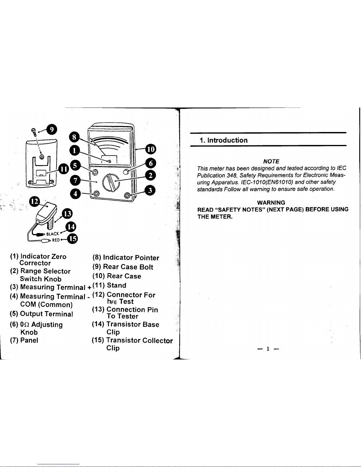
(1) Indicator Zero (8) Indicator Pointer
Corrector
(2) R S I t (9) Rear Case Bolt
ange e ec or
Switch Knob (10) Rear Case
(3) Measuring Terminal + (11) Stand
(4) Measuring Terminal - (12) Connector For
COM (Common) hFE Test
(5) 0 t t T . I (13) Connection Pin
u pu ermlna To Tester
(6) On Adjusting (14) Transistor Base
Knob Clip
l (7) Panel (15) Transistor Collector
Clip - 1 -
Page 3
2. Safety Notes 3. Feature
8 Read the following safety information carefully ') 8 Easy to read 3-color scale...for mistake proof
before attempting to operate or service the meter. reading.
8 Use the meter only as specified in this manual; 8 Mirror scale...makes reading pointer easy.
otherwise the protection provided by the meter may 8 Safety fused...on all ranges.
be impaired. . 8 Diode protected meter...prevents damage
8 Rated environmental conditions: due to overload.
(1). Indoor use. 8 Safety features...safety fused, safety "OFF"
(2). Installation Category II . position.
(3). Pollution Degree 2. 8 hFE and db measurement.
(4). Altitude up to 2000 Meter. 8 With stand...makes reading and measuring
(5). Relative Humidity 80% Max. easy.
(6). Ambient Temperature 0-40 DC. 8 Packaging...packed completely with
8 Observe the International Electrical Symbols listed AL-27 test leads, hFE leads, Fuse, instruc-
below. tion manual.
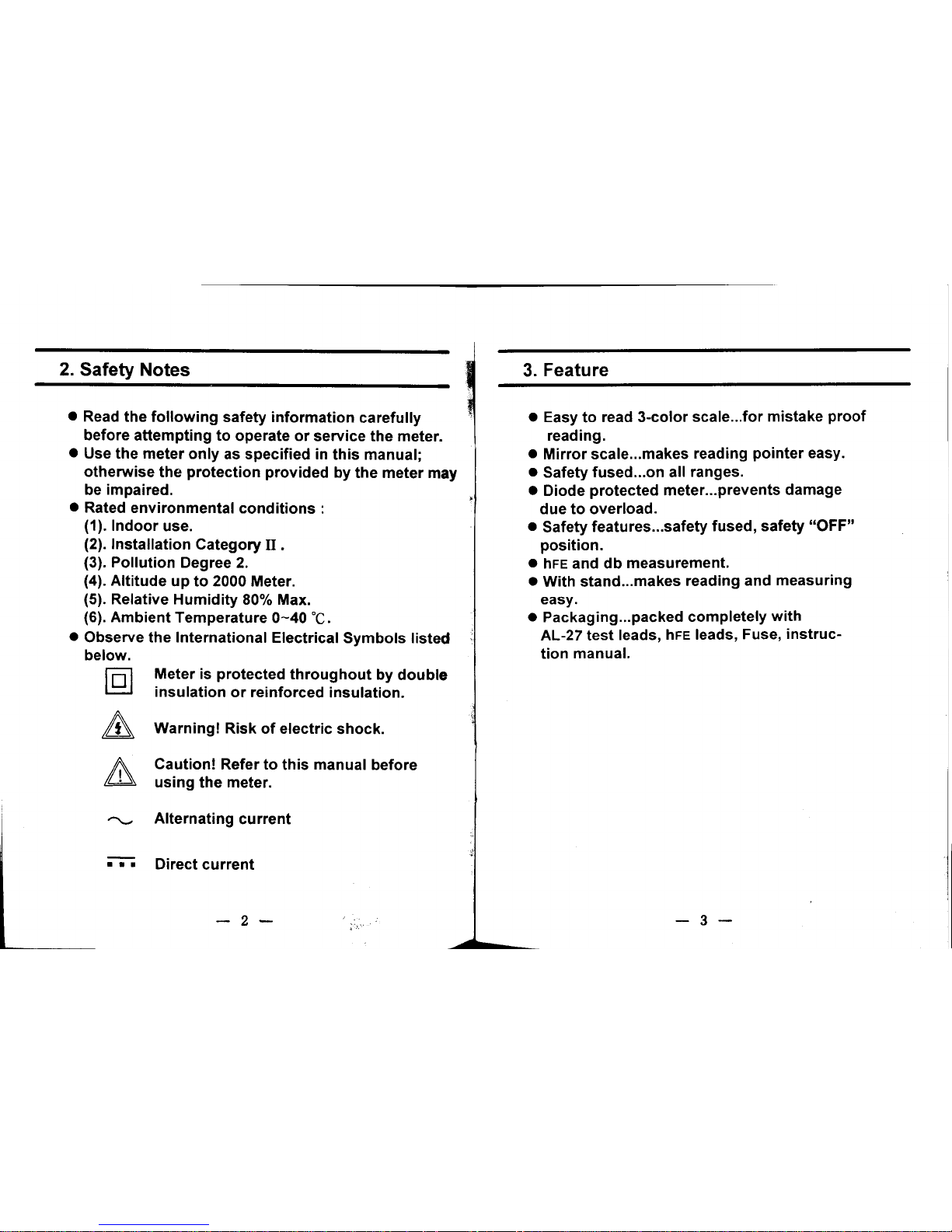
f"5l Meter is protected throughout by double
~ insulation or reinforced insulation.
& Warning! Risk of electric shock.
II:.. Caution! Refer to this manual before
m using the meter.
~ Alternating current
;-;-; Direct current
-2- -3-
Page 4
4. Specification Internal batteries: UM-3 X 2, 006P X 1
AF Output (dB)
. . Range: -10dB - +22dB(for 10VAC)- +62dB
1. As a circuit tester
I OdB/0.775V (1 mW through 6000 )
DC Voltage (DCV) Accuracy at FDS : :1:4%
Ranges: Output terminal: 9KQ/V
0-0.1-0.5-2.5-10-50-250-1000-25kV
Accuracy at FSD : :1:3% 2. As a transistor tester
Sensitivity: 20K Q/V Leakage Current (ICEO)
Extension: 25KV (with HV probe extra) Range: 0-150uA at X1k range
AC Voltage (ACV) 0-1.5mA at X100 range
Range: 0-15mA at X10 range
0-10-50-250-1000V 0-150mA at X1 range
Accuracy at FSD : :1:4% Accuracy at FDS : :1:5%
Sensitivity: 9K Q/V Current across terminals
Decibelmeter : 30Hz - 50KHz :l:1dB DC Current Amplification Factor (hFE) :
50Hz - 20KHz :1:3% Range: 0-1000 at 10 range (lc/IBC)
( 50V or less) Accuracy at FDS : :1:3% With connector extra
DC Current (DCA)
Range: l Size and Weight: 150(L)X100(W)X36(D) mm,
0-50uA- 2.5mA-25mA- 0.25A 50uA at 0.1VDC about 300 g
position Accessories: 5.241 X 20 spare fuse (250V/0.5)
Accuracy at FDS : :1:3% is supplied, Test lead, 1 pair.
Voltage drop: 250mV ( 100mV for 50uA) Optional accessories: TR. connector (HFE-6)
Resistance (0) HV probe (HIV-10),
Range: X1, X10, X100, X1K, X10K Carrying Case.
Minimum 0.2, 2, 20, 200, 200KO
Midscale 20, 200, 2K, 20K, 200KO
Maximum 2K, 20K, 200K, 2M, 20MO
Accuracy at FDS : :1:3%
-4- -5~ -
Page 5
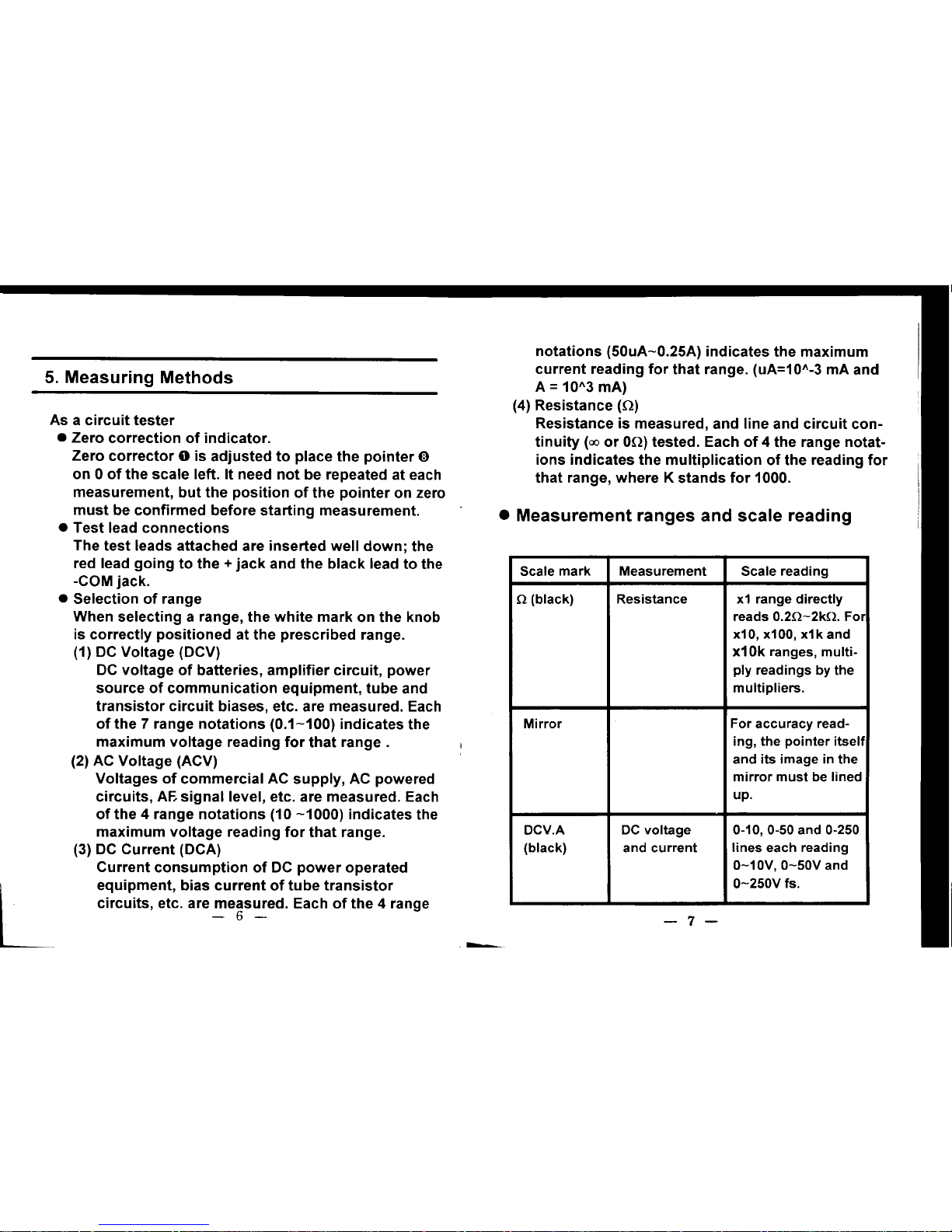
notations (50uA-0.25A) indicates the maximum
5 Measuring Method current reading for that range. (uA=101\-3 mA and
. S A=101\3mA)
(4) Resistance (0)
As a circuit tester Resistance is measured, and line and circuit con-
. Zero correction of indicator. tinuity (00 or 00) tested. Each of 4 the range notat-
Zero corrector 0 is adjusted to place the pointer 0 ions indicates the multiplication of the reading for
on 0 of the scale left. It need not be repeated at each that range, where K stands for 1000.
measurement, but the position of the pointer on zero
must be confirmed before starting measurement. . Measurement ranges and scale reading
. Test lead connections
The test leads attached are inserted well down; the
red lead going to the + jack and the black lead to the Scale mark Measurement Scale reading
-COM jack.
. Selection of range .0. (black) Resistance x1 range directly
When selecting a range, the white mark on the knob reads 0.2.o.-2k.o.. For
is correctly positioned at the prescribed range. x10, x100, x1k and
(1) DC Voltage (DCV) x10k ranges, multi-
DC voltage of batteries, amplifier circuit, power ply readings by the
source of communication equipment, tube and multipliers.
transistor circuit biases, etc. are measured. Each
of the 7 range notations (0.1-100) indicates the Mirror For accuracy readmaximum voltage reading for that range. ing, the pointer itself
(2) AC Voltage (ACV) and its image in the
Voltages of commercial AC supply, AC powered mirror must be lined
circuits, AF- signal level, etc. are measured. Each up.
of the 4 range notations (10 -1000) indicates the
maximum voltage reading for that range. DCV.A DC voltage 0-10,0-50 and 0-250
(3) DC Current (DCA) (black) and current lines each reading
Current consumption of DC power operated 0-10V, 0-50V and
L. equipment, bias current of tube transistor 0-250V fs. circuits, etc. are measured. Each of the 4 range
-6- -7-
-
Page 6

0.1V, 0.5V, 2.5V and
1000V are read mult- LV(blue) Voltage across Reads reverse DC
iplied. F~r current, 0 terminals voltage of 3V-0
-250(A) line reads
h'l .
w I e measuring
0-0.25A, 0-25mA .
ta 1kresls nce; x
and 0-25mA and through x1.
0-2.5mA, 0-50uA is
read on 0-50 line, dB(red) AF output -10-+22 dB for 10V
AC range. OdB is
ACV(red) AC voltage Common scale with .
established at
DCV reads 0-250V, 0.775V (1mW throu0-50V and 0-10V h 6000)
directly: For 0-1000 ~B=201091~
V: multiply the rea- 0.775V
ding on 0-10 line.
hFE(bl ) "" c I.f. BUZZER Continuity Built Buzzer sounds
ue J\. amp I Ica- Extra connector
h . ta '
. w en resls nce IS
tlon factor reads 0-1000 on I
201O( ess than O.
x 0) range.
LEAK,lcEO, Reverse leak- Reads current flow . Difference between voltage and current
LI(blue) age current across + and - COM measurements
of transistors while measuring j Fig. 1-A is a standard voltage measurement, where
resistance, x10 the potential difference between 2 points is checked,
range reading for which the meter is connected in parallel with
0-15mA. Emitter load, while -B checks the current supplied by power
and collector conne- and consumed by load, where the meter is connected
cted instead read in series with the circuit.
ICEO. 0-150uA for Basically, the difference is whether the meter is conx1k and 0-150mA nected in parallel or in series with load. The latter
for x10k ranges. connection accompanies the trouble of cutting open
the circuit being checked.
-8- -9-
Page 7

-l
A ".'0 B (JOV RANGE)
ru' " ...z..c& .. " . 0 ""O DOl
.. .. ~ .. R."DMX"'U'-U LOAD -- LOAD "'-" -U .
v, -, . ..
,",'OVRANGE --
.
.. .. ,, _OVALlE U
z...oo 1.77
Fig. 1 -COM .
F.
2Ig.
In respect of measurement loss, the bigger the imp- Consequently, the meter reads 3.77 V against the
edance of the meter (ZM) is, the smaller is the current actual4V resulting in some error. Therefore, when
(1M) required for measurement for the former, and, on measuring such a circuit, where R is usually replaced
the contrary, the smaller for impedance of the meter with a tube or a transistor, the circuit impedance and
is, the voltage loss (drop) by IL X ZM. (IL- current con- internal resistance of the voltage range of the tester
summation) used for measurement must be referred to each other
in reading the data obtained. In Fig. 2, the circuit impedance is about 1/10 of the impedance of the tester,
and reading error of within -5% can be ignored, though the bigger the internal impedance of a tester, the
. Voltage measurement and internal impedance better.
There are 2 instance of voltage measurement by par- The high impedance of 20 K!:W for DCV and 9 K!:W
allel connection. In case of Fig. 1-A, there exists no for ACV of this instrument displays its full ability in
high impedance corresponding to RA of Fig. 2. Power the voltage measurement of high impedance voltage
supply source has its own internal resistance, but it I amplifying circuit, ACV, AGC and transistor bias
is so small as can be ignored for voltage measurem- circuit to obtain high accuracy data.
ent, and the loss of current consumption by a tester Fig. 3 above is a sample measurement of a transistor
is practically nil the meter reading Ep. But, as can be circuit. It will be useful for trouble-shooting and disnote in Fig. 2, the circuit condition changes on acco- crimination of the type of the transistor used if you
Ii unt of RA present and 200KO of the tester connected are acquainted in advance with the proper use of
! in parallel for measurement. NPN and PNP transistors and the fact that Ge type
shows low VSE and Si type high VSE.
- 10 - - 11 -
---
Page 8

I
and + terminals to cut off DC element present on the
circuit to read AC signal alone on the meter.
"
;i Besides checking AF output voltage, this terminal is
~ I available to detect signals i.n TV servicing. For inst-
: J ance, on the AC 50V range IS detected the presence
C of the horizontal signal on the horizontal amplifying
1 circuit and, similarly, the presence of the input sign-
al on the synchronous detaching and synchronous
I amplifying circuits.
Fig. 3 ' . Resistance measurement and on adjustment
Resistance measurement is powered by internal
. Use of Hv probe for TV servicing batteries. They wear by use resulting in reading error
25 KV HV probe is available extra. It is connected as of the measured value. For correct reading of resistshown in Fig. 4 placing the range selector switch at ance, the sensitivity of the indicator must be adjustthe position marked PROBE. The DCV 0-250 scale is ed according to the voltage supplied by batteries.
used reading 25 KV at full scale. This probe can only This is what is called O-ohm adjustment for the indibe used for measurement of high impedance circuit cator to read on at full scale. It is adjusted in the
voltage like the anode and focusing voltages of a following way:
CRT for television use.
:=:- 0
1 ADJ
~ II '-'=-- @ -=-J Fig. 5
Fig. 4 As shown in Fig. 5, the range selector is placed at
II . ACV measurement on OUTPUT terminal the range being used. With the + and - COM termi-
I ii The negative lead is connected as usual to the -COM nals shorted together, the pointer movin~ toward
and the positive lead to the OUTPUT terminal. A co- on is adjusted by turning on ADJ to the right or left
,I ndenser is interconnected in series with the OUTPUT in order to place it exactly on 0 of the scale right.
- 12 - - 13 -
-
Page 9

The pointer must be adjusted each time the range
is mo.ved... Sw.position Max. current Max.voltage
(1) Polarity of termInals for resistance measurement consumption across terminals
As shown in Fig. 6, the polarity of terminals is
reversed for resistance measurement, the + jack x1 150mA 3V
being in negative and -COM jack in positive pote- x10 15mA 3V
ntial, the battery terminals being inverted in the \ x100 1.5mA 3V I
meter. It must be remembered when testing pola- x1k 150uA 3V
rized resistance like transistors and diodes 10k
(junction type), etc. So must it be when testing the x (60uA) (12V)
leakage of electrolytic capacitors.
00 ADJ . dB scale
.: dB (decibel) is measured in the same way as ACV
-COM ,-: measurement reading the dB scale instead.
Because the human ear is analogous to logarithmic
1 (t) L1 ,LV. 0 t variation, the input/output ratio of an amplifier and
I Fig. 6 transistor circuit is expressed by logarithmic value
dB to save complicated calculation. For a coupled
(2) Current consumption in resistance measurement circuit of a definite impedance, power can be comp-
Subject to the unit being tested, its impedance ared by simply expressing the voltage (current) ratio
changes while measuring resistance on account by dB. The dB scale provided is graduated to read
of the current flowing in the unit, or the voltage it from OdB to +22 dB on the reference of OdB at 0.775 V
is impressed with. Some abnormal state may be which is the voltage when 1mW is dissipated across
recognized due to selfheating. It must be well 6000.
noted for each range used when, for instance, Most frequently, the input and output circuit impedameasuring the DC resistance of a thin-wire coil nces of audio amplifiers are not necessarily standand a bulk-type semiconductor like a thermi- ardized for 6000, and the dB values measured by a
stor. The LI and LV scales provided check current tester are nothing but voltage values read in dB
li consumption and voltage load very effectively in corresponding to them. However, when comparing
i these measurements. AF voltage levels by dB, the scale provided will sure-
ly save the trouble of making complicated calculation
I - 14 - - 15 -
i
~
Page 10

when it is necessary to convert them into dB values. Represented electrically, Fig. 7 may otherwise be
(1) dB measurement on 50V, 250V and 1000V ranges as Fig. 8 where the section on the right of the N
For measurement on the 10V range, the dB scale and P terminals enclosed in the dotted line corre(-10dB-+22dB) is read directly, but, when measu- sponds to the internal circuit of the tester.
red on the 50V range, 14dB is added. On the 250V
range, 28dB is added to the reading on the scale, I N : i
and on the 1000V range, 40dB added. ICEO! c M !
Thus, the maximum dB readable is 22+40=62{dB) LEAK ~ + !
measured on the 1000V range. '~-- B IV =- !
As transistor tester °,/("", NPN-TR E . !
. Preliminaries ~ P' i
This instrument uses its resistance range for transis- k:EO . ' '-'
tor tests, and so the pointer must be exactly adjusted FIg. 8
to zero before connecting a transistor for measurem- (3) In Fig. 8, the current flowing across the P and N
ent, for which the P and N terminals are shorted toge- terminals is IcEo (reverse leakage current) of the
ther and the pointer is adjusted by 0.0. ADJ. TR, and the quantity of the leakage current is
. Measurement of IcEo (leakage current) read on the LEAK scale in mA.
(1) A small-size TR ( hereinafter a transistor is referr- (4) For a Si TR, this current is too small to read.
ed to as TR) is checked on the X10.o. (15mA) (5) There will be some leakage current read even for
range, and a large-size TR on the X 10 range. a good quality Ge TR, though there is some diff-
(2) An NPN TR is connected as shown in Fig. 7-A, and erence subject to its type. It will be 0.1mA -2mA
a PNP TR, in Fig. 7-B. for a small- and medium-size TR, and 1mA-5mA
A. B. for a large-size one.
~~ 0 ~::~c~ ~~ 0 (6) If the reading falls within the red LEAK zone of
0"1 0'. the ICEO scale, the TR tested is passable but if
N
~ N'" . .' @ p@ @ p@ It goes beyond the zone coming near to the full
-~ + -~ + scale, the TR is definitely defective.
1... I... (7) Leakage current is little to do with voltage value
~c r ~E r showing constant current characteristic but it is
_TR --TR -'
Fig. 7 a great deal subject to temperature. Be aware of
E C
L temperature rise while testing; it reads twice as
much for +10 DC.
-16 -
- 17.-
Page 11

. Measurement of hFE (DC amplification factor)
0-1000.
(1) Besides reverse leakage current, the amplificat-
ion degree of a TR kinetically measured also 0 0 0
determines the quality of a TR on a very simple 0
own in Fig. 9, there flows IcEo. A certain resis- @ p@ @ p@
tance (R) connected across the N terminal and .~ - .~ -
the base of the TR causes the current IA to flow c c
determined by R. For a good TR, Ic X hFE is led ~ _m __m~.
to the collector resulting in so much current inc- . .
rease and higher reading of the meter. The qua- Fig. 10
ntity of the current change can be scaled out as (3) The clips of the connector are connected to the
hFE on the meter to read the amplification deg- collector and base, and the lead from the other
ree. terminal of the tester, to the emitter.
(4) For a good TR, there will be a big difference of
reading between (1) and ('}) of Fig.11. In (1), when
IB = 0 and with base open, only a little IcEo is
read, and in ('}), IBflows and Ic changes reading
an increased value by 18 X hFE.
~\@ 1- tR -(I.'hFE)"'C '"
~ '" @
~I hF"~ a.t.
1_-
:J~ . , t;ig. 9 0 0
(2) Extra connector for hFE measurement (j) /
The connector is connected either to the N or P ~ ~ Fig. 11
terminal subject to the polarity of the TR. To the @~ ~.
other P or N terminal unemployed is connected
the emitter of the TR. The range switch is set for
X 10.
- 18 - - 19 -
---
Page 12

For a faulty TR : (2) IF reads high close to full scale, and IR very low
(a) No reading at all for the connection ~; practically no current flowing.
(b) No difference of reading between (1) and~; (3) While measuring IF, the LV scale reads the linear
(c) For the (1), reading goes beyond the hFE scale (forward) voltage of the diode tested. For a Ge
and near to full scale. I diode, it is usually 0.1-0.2V, and for Si diode,
(5) Under the condition of Fig. 11-~, reading is noted 0.5-0.8V.
on the blue hFE scale. The value read is IcllB wh- (4) The forward voltage of LED is generally more than
ich is the DC amplification degree of the TR tested. 1.5V, while average testers will fail to check it by
(6) Speaking exactly of aGe TR, leakage current alw- the connections of Fig. 12 to measure IF; it is imp-
ays flows to the collector resulting in so much re- ossible to have light emitted. The 3-volt internal
ading error. Therefore, true value is obtained by battery layout of the instrument effectively checks
deducting from hFE the value corresponding to it on the X 1 range. While light is being emitted,
ICEO read. the LI scale reads the current IF, and the LV scale
. Measurement of diode including LED the forward voltage VF.
(1) The connections of Fig. 12 read IF (forward current)
or IR (reverse current) on the LI scale provided. For
the 1K range, the scale reads 0 -150uA, for the X10
range 0-15mA, and for the X 1 range 0-150mA.
I"
IF» R \'
/ IF \
L I I \ Fig. 12
L__R ~ 14 _.\
- 20 - - 21 -
---
Page 13

6. Maintenance
8 Battery replacement 8 Arrangement of Parts
(1) If 00 adjustment is impossible in X10 range, the
two internal1.5V (UM-3, SUM-3, or R6) batteries
have worn out. Replace them with fresh ones.
(2) If 00 adjustment is impossible only in X10KO
range, re~lace the internal 9V (006P or 6F22) ~~E~~ ~~:E ~r:~r
battery with a new one.
D()@1.5V (3) To replace the batteries, open the rear case after
removal of the screw (4mm dia X 12 mm ) and B2 @ 0 ~
insert them into the battery compartment correct-
0 ~
I.'
IIy, taking note of their polarities. rIJ
8 Fuse replacement
(1) The internal fuse is blown if power voltage of AC -@-M- -@-
100V or more is inadvertently applied to the tester as g
~ -@- -fIB-
[)-8- -@"
with the range selector knob left set to current ,,$ -fB- ~-@-c.!L
ranges, especially to 0.25 A range, or to X10 ,,~ $~B- -@-T
range. .. OW -<!!>- $ M+
(2) When the fuse is blown, the tester fails to work. -@- -@-
Replace it with the spare fuse (5.2mm dia X 20mm, -@--fB- -fB250V/0.5A). Refer to Fig. 13 for its position. -@>--@-
Fig. 13
- 22 - - 23 L.-
Page 14

. List of major parts
RS D .. R19 Resistor (44k.o.), .0. series
. . escrlptlon
R1 R . 100 R20 Resistor (1S.o.), .0. x1 shunt
eslstor x
R2 R . t . I' R21 Resistor (200.0.), .0. x10 shunt
esls or series
R3 Resistor 5k.o. 0.5VDC multi lier R22 Resistor (330.3k.o.), .0. x1 k shunt
R4 Resistor (40k.o.), 2.5VDC multiplier R23 Resistor (190k.o.), .0. x10k series
R5 Resistor (150k.o.), 10VDC multiplier R24 Resistor 15k.o., shunt
R6 Resistor (SOOk.o.), 50VDC multiplier R25 YR. (10k.o.), 0.0. adjuster
R7 Resistor (4M.o.), 250VDC multiplier R26 Resistor (2.0Sk.o.), .0. x100 shunt
RS Resistor (15M.o.), 1000VDC multi lier R27 Resistor (0.0.), multiplier
R9 Resistor (3k.o.), series D1,D2 Silicon diode for ACV
R10 Resistor (102.0.), 2.5mADC shunt D3,D4 Silicon diode for protection
R11 Resistor unt C1 Capacitor 473 for OUTPUT
C2 Capacitor 403
R13 Resistor (75k.o.), 10VAC multiplier B1 Battery 1.5V (UM-3 or R6) 2 required
R14 Resistor (320k.o.), 50VAC multiplier B2 Battery 9V (006P or 6F22)
R15 Resistor (1.6M.o.), 250VAC multiplier F Fuse (250V/0.4A) size 5.20 x 20mm
R16 Resistor (6M.o.), 1000VAC multiplier SW Range selector switch
R17 Resistor (24k.o.), shunt M Meter movement (44uA/2000.o. abt.)
R1S Resistor (2k.o.), diode series
- 24 - - 25 -
---
Page 15

Rear case
Terminal jack, 40, 3 required
Range selector switch knob
on ad b
Test I air
",."C 'c )\""'~
RS ,Reference Symbol ""c; !f~iC'.J",,1~-
. Cleaning and Storage: ;
WARNING
To avoid electrical shock or damage to the meter,
do not get water inside the case.
Periodically wipe the case with a damp cloth and
detergent; do not use abrasives or solvents.
If the meter is not to be used for periods of longer
than 60 days, remove the batteries and store them
separately.
- 26-
 Loading...