

Watlow SSR-240-10A-DC1, SSR-240-25A-DC1, SSR-240-50A-DC1, SSR-240-10A-AC1, SSR-240-25A-AC1 Specifications
...Page 1
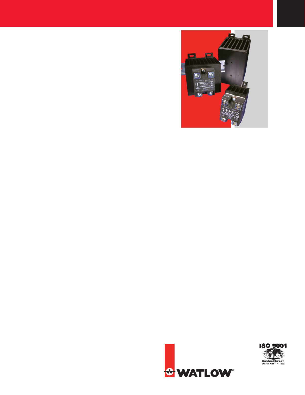
Solid State Relay
Solid State Relay Offers
More For Less: Longer
Heater Life at Lower Cost
®
Watlow
advantages of solid state power controllers, yet at a lower
cost. Watlow’s extensive knowledge in power controller
design has led to the development of a special fast cycle
input card that enables a SSR to operate from a standard
4-20mA instrumentation command signal. Test results
have shown that a zero cross SSR in combination with the
fast cycle card promotes better temperature control and
longer heater life than slow cycle relays. Through a time
proportional cycle rate of one tenth of a second heater life
will be extended.
Both low and high voltage models are available from
24 up to 530VAC. All ac output models include back to back
Silicon Controlled Rectifiers (SCRs) for a more rugged design
than the traditional triac based SSR. The internal design
allows it to handle high currents and the harsh electrical
environments of heavy industry. Watlow also offers a
switched VDC model for dc heating applications.
Watlow can provide all the components necessary
for trouble-free operation. This includes two standard
convenience items: a thermal foil to ensure proper thermal
transfer from the relay to the heat sink and belville washers
that ensure the relay is mounted with sufficient pressure for
good heat transfer. Matched semiconductor fuses and heat
sinks are available to complete the power switching package.
solid state relays (SSR) offer many of the
Features and Benefits
Fast cycle card
• Increases heater life
• Optimizes temperature control
• Allows for higher watt density heaters
Zero cross firing
• Results in minimal electrical noise
Back-to-back SCR design
• Withstands harsh or hostile industrial environments
UL® recognized File #E151484 and #E73741;
CSA certified File #LR700195; VDE 60950
License #40021401, File #1995500 up to 480VAC
• Meets applications requiring agency approval
© 2013 Watlow Electric Manufacturing Company
WIN-SSR-0413
Page 2
Specifications
07
Load Current (Amperes)
Specifications Standard To All SSRs:
Dielectric Strength (Volts) 4000 RMS
Input, DC Control
Voltage range 3-32VDC
Typical input current 3.4 to 20mA
Turn on voltage (max.) 3VDC
Turn off voltage (min.) 1VDC
Input, AC Control
Voltage range 90-280VAC
Typical input current 2mA (typical) @ 120VAC
4mA (typical) @ 240VAC
Turn on voltage (max.) 90VAC
Turn off voltage (min.) 10VAC
AC Output (Max.)
Forward voltage drop 1.5VAC and 2.1VDC
Min. holding current (mA) 50mA
Turn on-off time (ms) up to 10ms (max.)
Frequency range 47 to 63Hz
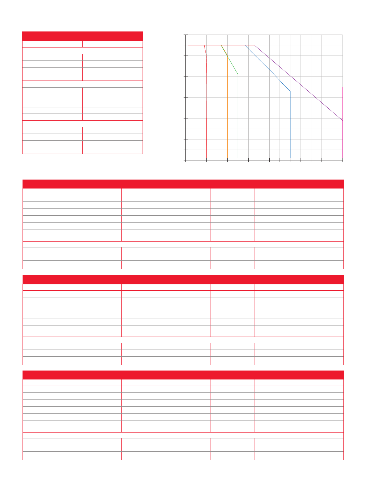
Ambient Temperature Operating Curve
85
80
75
70
65
60
55
50
45
Ambient temperature inside enclosure
3 inches left or right of the heatsink (ºC)
40
35
30
25
SSR-240-10A-XXX and Z100-0815-000A Heatsink
51015202530354045505560657
SSR-XXX-25A-XXX and Z100-0815-000B Heatsink
SSR-100-20A-DC1 and Z100-0815-000B Heatsink
SSR-XXX-75A-XXX and Z100-0815-000C Heatsink
SSR-XXX-50A-XXX and Z100-0815-000C Heatsink
SSR-XXX-75A-XXX and
Z100-0815-XXFC Heatsink
120/240VAC
Model Number
Current output 10A 25A 50A 10A 25A 50A
Nominal voltage 120/240VAC 120/240VAC 120/240VAC 120/240VAC 120/240VAC 120/240VAC
One cycle surge current 120A 250A 625A 120A 250A 625A
2
Max. I
t for fusing 60A2 seconds 260A2 seconds 1,620A2 seconds 60A2 seconds 260A2 seconds 1,620A2 seconds
Thermal resistance 1.48° C/W 1.05° C/W 0.63° C/W 1.48° C/W 1.05° C/W 0.31° C/W
Ambient operating
temperature
Output (Max.)
Voltage range 48-280VAC 48-280VAC 48-280VAC 48-280VAC 48-280VAC 48-280VAC
Over voltage rating 600V (peak) 600V (peak) 600V (peak) 600V (peak) 600V (peak) 600V (peak)
Off state leakage 10mA 10mA 10mA 10mA 10mA 10mA
SSR-240-10A-DC1 SSR-240-25A-DC1 SSR-240-50A-DC1 SSR-240-10A-AC1 SSR-240-25A-AC1 SSR-240-50A-AC1
-40 to 176°F
(-40 to 80°C)
-40 to 176°F
(-40 to 80°C)
-40 to 176°F
(-40 to 80°C)
-40 to 176°F
(-40 to 80°C)
-40 to 176°F
(-40 to 80°C)
-40 to 176°F
(-40 to 80°C)
5
120/240VAC Random Fired Models 100VDC
Model Number
Current output 75A 75A 50A 75A 10A 20A
Nominal voltage 120/240VAC 120/240VAC 480VAC 480VAC 120/240VAC 100VDC
One cycle surge current 1000A 1000A 625A 1000A 120A 42A (10ms)
2
Max. I
t for fusing 6000A2 seconds 6000A2 seconds 1,620A2 seconds 6000A2 seconds 60A2 seconds N/A
Thermal resistance 0.31° C/W 0.31° C/W 0.63° C/W 0.31° C/W 1.48° C/W 1.06° C/W
Ambient operating
temperature
Output (Max.)
Voltage range 48-280VAC 48-280VAC 80-530VAC 80-530VAC 48-280VAC 0-100VDC
Over voltage rating 600V (peak) 600V (peak) 1200V (peak) 1200V (peak) 600V (peak) N/A
Off state leakage 10mA 10mA 10mA 10mA 10mA 0.3mA VDC
SSR-240-75A-DC1 SSR-240-75A-AC1
-40 to 176°F
(-40 to 80°C)
-40 to 176°F
(-40 to 80°C)
SSR-480-50A-
-40 to 176°F
(-40 to 80°C)
RND
SSR-480-75A-
-40 to 176°F
(-40 to 80°C)
RND
SSR-240-10A-
-40 to 176°F
(-40 to 80°C)
RND SSR-100-20A-DC1
-4 to 176°F
(-20 to 80°C)
480 VAC
Model Number
Current output 25A 50A 75A 25A 50A 75A
Nominal voltage 480VAC 480VAC 480VAC 480VAC 480VAC 480VAC
One cycle surge current 250A 625A 1000A 250A 625A 1000A
2
Max. I
t for fusing 260A2 seconds 1,620A2 seconds 6,000A2 seconds 260A2 seconds 1,620A2 seconds 6,000A2 seconds
Thermal resistance 1.02° C/W 0.63° C/W 0.31° C/W 1.02° C/W 0.63° C/W 0.31° C/W
Ambient operating
temperature
Output (Max.)
Voltage range 48-530VAC 48-530VAC 48-530VAC 48-530VAC 48-530VAC 48-530VAC
Over voltage rating 1200V (peak) 1200V (peak) 1200V (peak) 1200V (peak) 1200V (peak) 1200V (peak)
Off state leakage 10mA 10mA 10mA 10mA 10mA 10mA
SSR-480-25A-DC1 SSR-480-50A-DC1 SSR-480-75A-DC1 SSR-480-25A-AC1 SSR-480-50A-AC1 SSR-480-75A-AC1
-40 to 176°F
(-40 to 80°C)
-40 to 176°F
(-40 to 80°C)
-40 to 176°F
(-40 to 80°C)
-40 to 176°F
(-40 to 80°C)
-40 to 176°F
(-40 to 80°C)
-40 to 176°F
(-40 to 80°C)
Page 3
Heater Life
Temp
Watlow has extensively tested electric heating elements with
a variety of power switching devices. Results prove that the
life of an electric element dramatically increases when the
on-off cycle time that is used to time-proportion the heater
is kept at less than one second. This reduces the thermal
expansion and contraction of the element and improves
heater life as much as 20 times. This very fast cycle time
controls temperature much more accurately and allows the
use of higher watt density heating elements.
Fast Cycle Card
In order to obtain the very rapid cycling time required for
longer heater life, accurate temperature control and higher
watt densities, Watlow has developed a loop-powered
firing card for SSRs. This card operates from a standard
instrumentation signal of 4 to 20mA and controls solid state
relays with a time proportional cycle rate of less than one
second (4VAC cycles on and 4VAC cycles off at 50 percent
power).
Thermal Transfer
A thermal foil is provided with each solid state relay for
mounting on the base of the relay to improve heat transfer.
In addition, two belville washers are supplied to provide
the proper pressure for this transfer of heat. Use two #8-32
screws 0.625 in. (16 mm) long to secure the relay to
the heat sink.
Replacing Contactors or Mercury Displacement Relays (MDRs)
Improvements in heater life and control accuracy can be
achieved with SSRs operated with rapid cycle times as
compared to slower operating electromechanical relays or
even MDRs. When replacing these types of relays with the
SSR, it is important to consider two aspects:
1. Heat
Solid state devices require a small voltage to turn
on, which is consumed as heat (approx. 1.5 volts x
amps = watts). This heat must be removed from the
device and is usually accomplished by mounting the
relay on a heat sink.
2. Failure Mode
Solid state devices should last for many years
when properly protected with voltage snubbers,
mounted on appropriate heat sinks and when fused
with semiconductor fuses against the high currents
caused by electrical shorts. Watlow’s SSRs include
an internal voltage snubber. However, if the unit
fails, the most probable condition will be a short.
Mechanical relays also have a good probability of
failing short. In all cases where uncontrolled full power
can cause damage, it is recommended that a high
limit temperature controller and contactor be used for
protection.
Wiring Diagrams
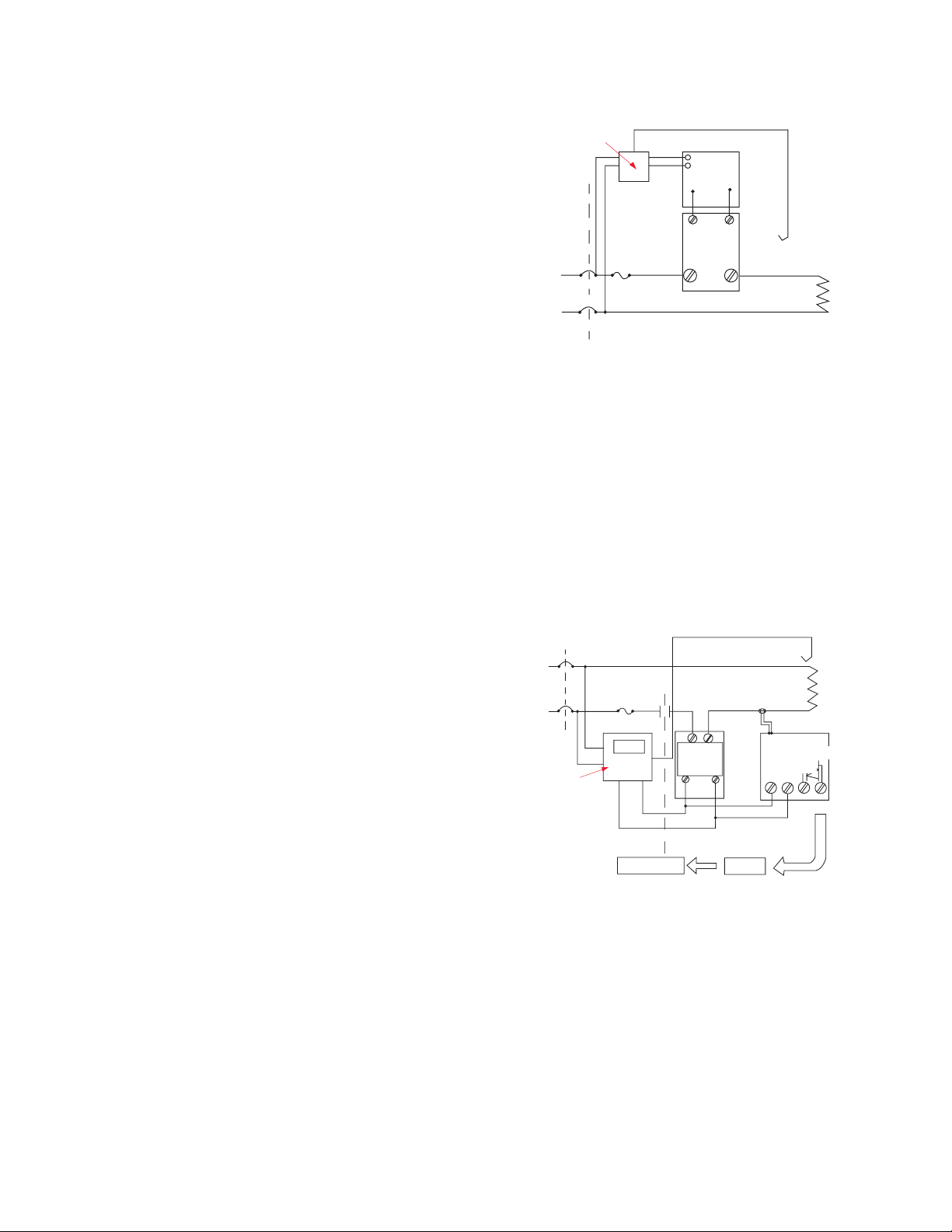
Single-Phase Fast Cycle Input Card
Control
Input
4-20
mA VDC
Output
L1
L2
Fuse
Shorted SSR Alarm
The most prevalent concern when using solid state relays is
the possibility of a relay failing in a shorted condition. With
this in mind, Watlow has designed a cost effective “Shorted
SSR Alarm”.
The device monitors the output (current through the heater)
and activates a triac (alarm) if there is no command signal
from the temperature controller. The triac can be wired to a
bell, or to a normally closed latching relay to remove power
to the heater.
The shorted SSR alarm is not a substitute for an
agency-approved high-temperature limit device.
Single-Phase Shorted SSR Detector
L1
L2
Temp
Control
Open
Collector
Contactor
Note: Semiconductor power switching devices are not legal
for over temperature limit or safety devices. For limit and
safety devices you must have a positive mechanical break of
all electrically hot legs simultaneously.
Card
+-
DC
SSR
Thermocouple
Solid
State
Relay
D.C.
-+
0 and
5VDC
on-off
Relay
Heater
Transformer
Shorted SSR
Detector
Heater
Mounted
Current
Page 4
F
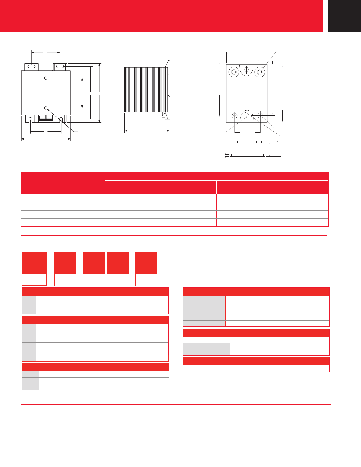
Dimensions - Heat Sink
E
47.8 mm
C
(1.88 in.)
A
B
Drilled and
Tapped 8-32
D
F
Dimensions - Solid State Relay
4.8 mm
(0.19 in.)
47.63 mm
(1.875 in.)
4.37 mm
(0.172 in.) Dia.
2 Places
3 mm
(0.12 in.)
44.5 mm
(1.75 in.)
28 mm
(1.1 in.)
13.5 mm
(0.53 in.)
25 mm
(1 in.)
8 mm
(0.3 in.)
43 mm
(1.7 in.)
19.6 mm
(0.77 in.)
Thread
57.2 mm
(2.25 in.)
6-32 Thread
23 mm
(0.9 in.)
Case Temp.
8-32
Ref. Point
Heat Sink Dimensions by Part Number
Dimensions
Code Number Descriptor
in. (mm)
Z100-0815-000A 18A N/A 1.8 (46) 3.25 (82.6) 3.7 (94) N/A 1.9 (48)
Z100-0815-000B 35A 1.91 (48.5) 3.2 (81) 3.25 (82.6) 3.7 (94) 1.81 (46) 2.9 (74)
Z100-0815-000C 55A 1.89 (48) 3.2 (81) 5.45 (138.4) 5.89 (149.6) 1.81 (46) 3.6 (91)
Z100-0815-XXFC* 75A 1.89 (48) 3.2 (81) 5.45 (138.4) 7.16 (181.9) 1.81 (46) 3.6 (91)
*Fan cooled
A
B
in. (mm)
C
in. (mm)
D
in. (mm)
E
in. (mm)
F
in. (mm)
Ordering Information
Part Number
①
③
②
⑤④⑥
Voltage
SSR
-
⑤④⑥
100 =
0 to 100VDC (20A model only)
240 =
24 to 240VAC
480 =
24 to 530VAC
⑦
⑧
10 =
10A
20 =
20A (100VDC model only)
25 =
25A
40 =
40A
50 =
50A
75 =
75A
⑩ ⑪ ⑫
DC1 =
AC1 =
RND =
3 to 32VDC (see specifications)
90 to 280VAC
3 to 32VDC (10, 50 and 75A models only)
⑦
⑧
Current
- -
Voltage
Current
Control Voltage
⑨
A
Note: Relay will also include thermal foil, two belville washers and
#8-32 screws for mounting to a heat sink.
⑩ ⑪ ⑫
Control
Voltage
Heat Sinks (sold separately)
Z100-0815-000A =
Z100-0815-000B =
Z100-0815-000C =
Z100-0815-12FC =
Z100-0815-24FC =
18A or 2.2°C/watt
35A or 1.1°C/watt
55A or 0.6°C/watt
75A or 0.16°C/watt (120VAC fan)
75A or 0.16°C/watt (240VAC fan)
Fast Cycle Input Card and Shorted SSR Alarm Card
For direct mounting on zero cross dc input solid state relay.
RPC-5399-42-000 =
RPC-5386-0000 =
Fast cycle input card, 4 to 20mA input
Shorted SSR alarm card
Sub Cycle Fuses - I2T (sold separately)
Recommended and available with holders.
®
Watlow
is a registered trademark of Watlow Electric Manufacturing
Company.
UL® is a registered trademark of Underwriter’s Laboratories, Inc.
To be automatically connected to the nearest North American Technical Sales Office:
1-800-WATLOW2 • www.watlow.com • [email protected]
International Technical Sales Offices: Australia, +61 3 9335 6449 • China, +86 21 3532 8532 • France, +33 1 41 32 79 70
Germany, +49 (0) 72 53 / 94 00-0 • India, +91 40 6661 2700 • Italy, +39 024588841 • Japan, +81 3 3518 6630 • Korea, +82 2 2628 5770
Malaysia, +60 3 8076 8745 • Mexico, +52 442 217 6235 • Singapore, +65 6773 9488 • Spain, +34 91 675 12 92
Taiwan, +886 7 288 5168 • United Kingdom, +44 (0) 115 964 0777
 Loading...