

Page 1
Registered Company
Winona, Minnesota USA
ISO 9001
TOTAL
3Year Warranty
CUSTOMER
SATISFACTION
Power Series
User’s Manual
Microprocessor-Based
SCR Power Controller
U.S. English
0600-0039-0000 Rev H Made in the U.S.A.
July 2012 $10.00
Supersedes: 0600-0039-0000 Rev G
1241 Bundy Boulevard, P.O. Box 5580, Winona, Minnesota USA 55987-5580
Phone: +1 (507) 454-5300, Fax: +1 (507) 452-4507 http://www.watlow.com
Page 2

Safety Information in this Manual
Note, caution and warning symbols appear throughout this book to draw your
attention to important operational and safety information.
A “NOTE” marks a short message to alert you to an important detail.
A “CAUTION” safety alert appears with information that is important for
protecting your equipment and performance.
A “WARNING” safety alert appears with information that is important for
protecting you, others and equipment from damage. Pay very close attention
to all warnings that apply to your application.
The ç symbol (an exclamation point in a triangle) precedes a general
CAUTION or WARNING statement.
The Ó symbol (a lightning bolt in a lightning bolt in a triangle) precedes an
electric shock hazard CAUTION or WARNING safety statement.
Technical Assistance
If you encounter a problem with your Watlow controller, see the Troubleshooting Table in the Appendix and review all of your configuration
information to verify that your selections are consistent with your application:
inputs; outputs; alarms; limits; etc. If the problem persists after checking the
above, you can get technical assistance from your local Watlow representative,
or by dialing +1 (507) 454-5300, 7:00 a.m. to 7:00 p.m. Central Standard Time.
An applications engineer will discuss your application with you.
Please have the following information available when you call:
• Complete model number • All configuration information
• User’s Manual • Diagnostic Menu readings
Warranty and return information are on the back cover of this
manual.
Your Comments
Your comments or suggestions on this manual are welcome. Please send them
to the Technical Literature Team, Watlow Winona, 1241 Bundy Boulevard,
P.O. Box 5580, Winona, Minnesota, 55987-5580 U.S.; Telephone: +1 (507) 454-
5300; fax: +1 (507) 452-4507. The Power Series User’s Manual is copyrighted
by Watlow Winona, Inc., © 2007, with all rights reserved. (2211)
ç
Safety Alert
CAUTION or
WARNING
∫
Electrical
Shock Hazard
CAUTION or
WARNING
Page 3

Chapter 1: Overview . . . . . . . . . . . . . . . . .1.1
Chapter 2: Installation . . . . . . . . . . . . . . . .2.1
Dimensions . . . . . . . . . . . . . . . . . . . .2.2
Mounting the Power Series . . . . . . . . .2.2
Enclosure Guidelines . . . . . . . . . . . . .2.3
Harsh Environments . . . . . . . . . . . . . .2.3
Removing the Power Series . . . . . . . .2.4
Maintaining the Power Series . . . . . . .2.4
Output Rating Curves . . . . . . . . . . . . .2.5
Chapter 3: Wiring . . . . . . . . . . . . . . . . . . .3.1
Torque Guidelines . . . . . . . . . . . . . . .3.1
Input Wiring . . . . . . . . . . . . . . . . . . . .3.2
Line Power/Output Wiring . . . . . . . . . .3.4
Wiring Example . . . . . . . . . . . . . . . . .3.6
Chapter 4: Navigation and Software . . . . .4.1
Keys and Displays . . . . . . . . . . . . . . .4.1
Navigation . . . . . . . . . . . . . . . . . . . . .4.2
Software Map . . . . . . . . . . . . . . . . . . .4.3
Chapter 5: Control Methods and Features .5.1
Zero Cross . . . . . . . . . . . . . . . . . . . . .5.1
Phase Angle . . . . . . . . . . . . . . . . . . . .5.2
Other Features . . . . . . . . . . . . . . . . . .5.6
Input . . . . . . . . . . . . . . . . . . . . . . . . .5.6
Alarms . . . . . . . . . . . . . . . . . . . . . . . .5.7
Communications . . . . . . . . . . . . . . . .5.8
Retransmit . . . . . . . . . . . . . . . . . . . . .5.9
Fast Start Guide . . . . . . . . . . . . . . . . .5.10
Chapter 6: Parameters . . . . . . . . . . . . . . 6.1
Display Loop . . . . . . . . . . . . . . . . . . .6.1
Setup Page . . . . . . . . . . . . . . . . . . . .6.5
Factory Page . . . . . . . . . . . . . . . . . . .6.14
Factory Mode . . . . . . . . . . . . . . . . . . .6.20
Appendix . . . . . . . . . . . . . . . . . . . . . . . . .A.1
Troubleshooting . . . . . . . . . . . . . . . .A.2
Troubleshooting Alarms and Errors . .A.4
Checking and Replacing Fuses . . . . .A.6
Power Series Backup . . . . . . . . . . . . .A.7
Modbus™ Register Numbers . . . . . . .A.8
Product Specifications . . . . . . . . . . . .A.9
Ordering Information . . . . . . . . . . . . .A.10
Index . . . . . . . . . . . . . . . . . . . . . . . . .A.11
Prompt Index . . . . . . . . . . . . . . . . . . .A.13
CE Declaration of Conformity . . . . . . .A.14
Warranty and Returns Policy . . .back cover
T
Power Series
Table of Contents
Table of Contents Watlow Power Series ■ i
Page 4

ii ■ Watlow Power Series Table of Contents
Page 5
1
Overview, Chapter 1 Watlow Power Series ■ 1.1
Chapter One
Overview
Introduction
The Power Series is a state-of-the-art microprocessor-based Silicon Controlled Rectifier
(SCR) power controller intended for controlling industrial heaters. This product is based on
one package with several configurations that include single phase, three phase, and single
phase-multizone capabilities. Each package configuration has a specific current rating
depending on the number of phases switched. The switching capabilities include 65 to 250A
rms at 50°C from 24 to 600V~ depending on the configuration or model number selected. See
page 1.2 for additional information on the Power Series configuration options.
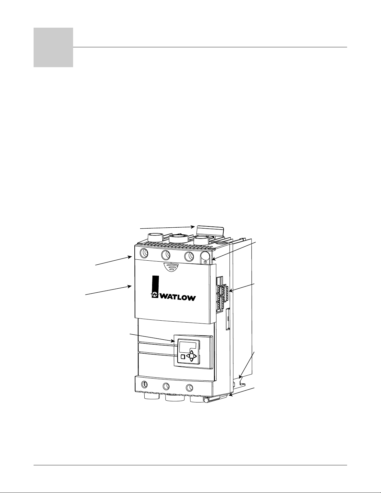
Figure 1.1 — Power Series features.
Removable Mounting Plate
Power Series snaps on a premounted, removable plate.
Terminal Cover
Electrically touch-safe
package.
Fuse Cover
Slides up and down for fuse
maintenance and covers the
high voltage components.
Digital Programmer/Display
For controller configuration,
setup, and monitoring features.
1
2
Power Series
Solid State Power Control
Ground Lug
Built in, designed for easy
3
ground connections.
I/O Port
Input, retransmit
output, communications,
and alarms.
On-Board Fan
A fan is integrated into
the package on forced
air cooled models to
eliminate separate power
connection for fan.
4
5
6
Allen Wrench
Used to torque terminals
1 to 6 and ground lug.
Page 6

Single Phase
This configuration can be purchased with any or all the features available on the Power
Series. The only limitations are the features selected by the customer upon purchase. It has
the highest current rating of all configurations since it is only switching one phase of the ac
line. It is intended for resistive heaters, but can also be used on transformer connected loads
in the phase angle firing mode.
Three Phase, Two-Leg Configuration
This configuration is intended for zero cross firing into a stable resistive heater, i.e.,
nichrome element. Typically, a three phase, three-wire delta or ungrounded wye/star connected heater is most often used where only two of the three V~ line phases are switched.
The third phase is a direct connection through a bussbar on board the Power Series and is
controlled by the previous two phases. For this reason, a two-leg configuration should not be
used for three phase grounded wye/star connected heaters. (For heaters that are required to
be three phase grounded wye/star connected, see “Three Phase, Three-Leg Configuration”
section below.)
Because this configuration does not allow phase angle firing, it should not be used on
transformer coupled heaters and less stable resistance heaters such as silicon carbide,
molybdenum disilicide, carbon graphite, or tungsten lamp heaters. This may cause
premature heater failure or nuisance fuse blowing.
Heater current monitoring and kVA options are available with a three phase, two-leg configuration via the heater diagnostics option. Phase angle firing, including current limiting and
heater bakeout, is not available.
Three Phase, Three-Leg Configuration
There are two Power Series configurations that include six SCR control. All features are
available in these configurations.
The three-leg version is intended for phase angle firing into a transformer connected load or
direct connection to heating that requires soft start and/or current limiting.
The four-wire configuration is intended for zero cross firing into a four-wire wye connected
nichrome/resistive heater.
Single Phase, Multizone Configuration
This configuration is available in two and three single phase zones. Back-to-back SCRs are
used and all of the features of a single phase unit are available. (Note that there is only one
alarm relay and all zones in the controller must use the same control method.) This configuration is intended for applications with multiple command signals from independent control
zones. The multizone platform offers reduced panel space compared to using multiple single
phase power controllers.
Heater Diagnostics
Heater diagnostics is a key feature of the Power Series SCR power controller. Heater
diagnostics may include all or only some of the features that require heater current
monitoring, depending on the model selected. Heater current monitoring is only available
with heater diagnostics installed on the controller. The features dependent on heater current monitoring are heater bakeout, current limiting, heater current and kVA monitoring,
retransmit, and heater monitoring alarms such as open heater, heater out of tolerance, load
balance, and shorted SCR detection/error. Heater diagnostics must also be installed if you
need phase angle control with current limit.
1.2 ■ Watlow Power Series Overview, Chapter 1
Page 7
Chapter Two
Installation
Installation, Chapter 2 Watlow Power Series I 2.1
2
The following two chapters will explain how to install the Power Series
controller. Watlow power controllers are thoroughly tested before leaving the
factory, so the Power Series controller is ready to install when you receive it.
Chapters 2 and 3 describe the steps required to install the Power Series
controller. Refer to Chapter 2 for mounting information and Chapter 3 for input,
power, and load wiring of the Power Series.
Before beginning installation, read through these chapters to gain an understanding of the entire installation. Consider the installation carefully. Plan the
power, load, and input signal wiring before mounting the Power Series. Also
consider the cabinet space, controller dimensions, wire bending radius, and airflow. Use good wiring practices to minimize electrical noise problems.
∫
WARNING:
To avoid potential electric
shock and other hazards,
all mounting and wiring
for the Power Series must
conform to the National
Electric Code (NEC) and
other locally applicable
codes.
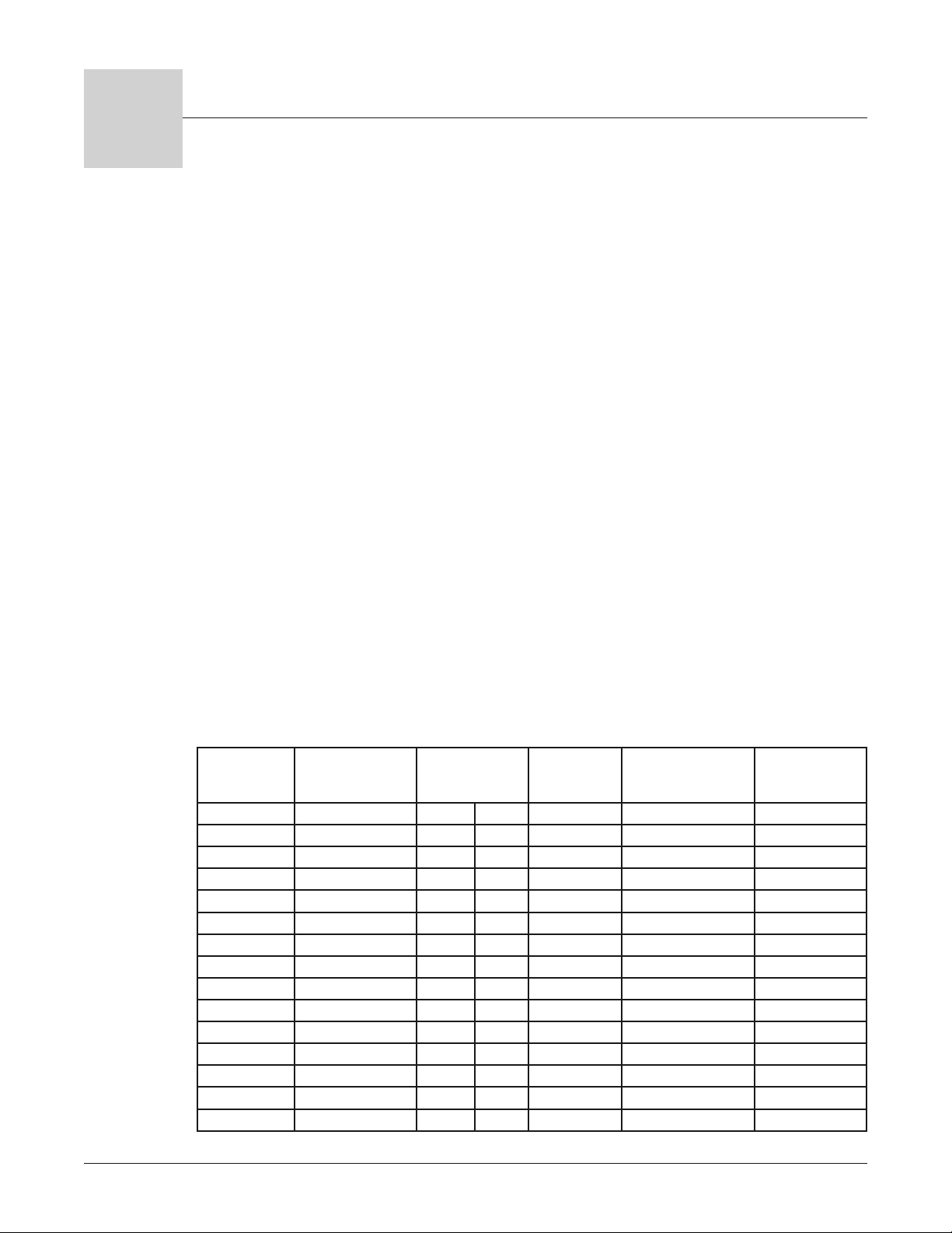
Power Series Wire Bending Radius at Base Current and Ambient
Temperature Rating and Replacement Semiconductor Fuses
Minimum recommended wire sizes are based on the NEC 30°C ambient with not
more than three current carrying conductors in raceway or cable, while also
considering the Power Series 50°C enclosure temperature and semiconductor
fuse rating. Use copper conductors only.
The terminal lug wire range for all Power Series amperages is 350 MCM to 6
AWG. The recommended terminal torque is 180 in.-lbs. (20 Nm.). Refer to page
3.1 for torque guidelines.
NOTE: Ground must be
wired with the same size
wire as line and load
connections to a ground
of sufficient current
carrying capacity.
NOTE: Integral semiconductor fuses do not
qualify as branch circuit
protection.
Power Series
Current (Amps)
Minimum
Recommended Wire
Size (90C) (AWG)
Wire Bending
Radius
mm inches
Semiconductor
Fuse Rating
(Amps)
Watlow Replacement
fuse P/N
Bussmann
Replacement Fuse
P/N
65 6 AWG 51 2.0 100 0808-0102-0100 170M1317
80 4 76 3.0 125 0808-0102-0125 170M1318
85 4 76 3.0 125 0808-0102-0125 170M1318
90 4 76 3.0 125 0808-0102-0125 170M1318
100 3 76 3.0 160 0808-0102-0160 170M1319
105 3 76 3.0 160 0808-0102-0160 170M1319
120 2 89 3.5 160 0808-0102-0160 170M1319
125 2 89 3.5 160 0808-0102-0160 170M1319
140 1 114 4.5 200 0808-0102-0200 170M1320
155 1/0 140 5.5 200 0808-0102-0200 170M1320
160 1/0 140 5.5 250 0808-0102-0250 170M1321
165 1/0 140 5.5 250 0808-0102-0250 170M1321
185 2/0 152 6.0 250 0808-0102-0250 170M1321
200 3/0 165 6.5 250 0808-0102-0250 170M1321
250 250 MCM 216 8.5 315 0808-0102-0315 170M1322
Page 8
2.2 I Watlow Power Series Installation, Chapter 2
Mounting the Power Series Controller
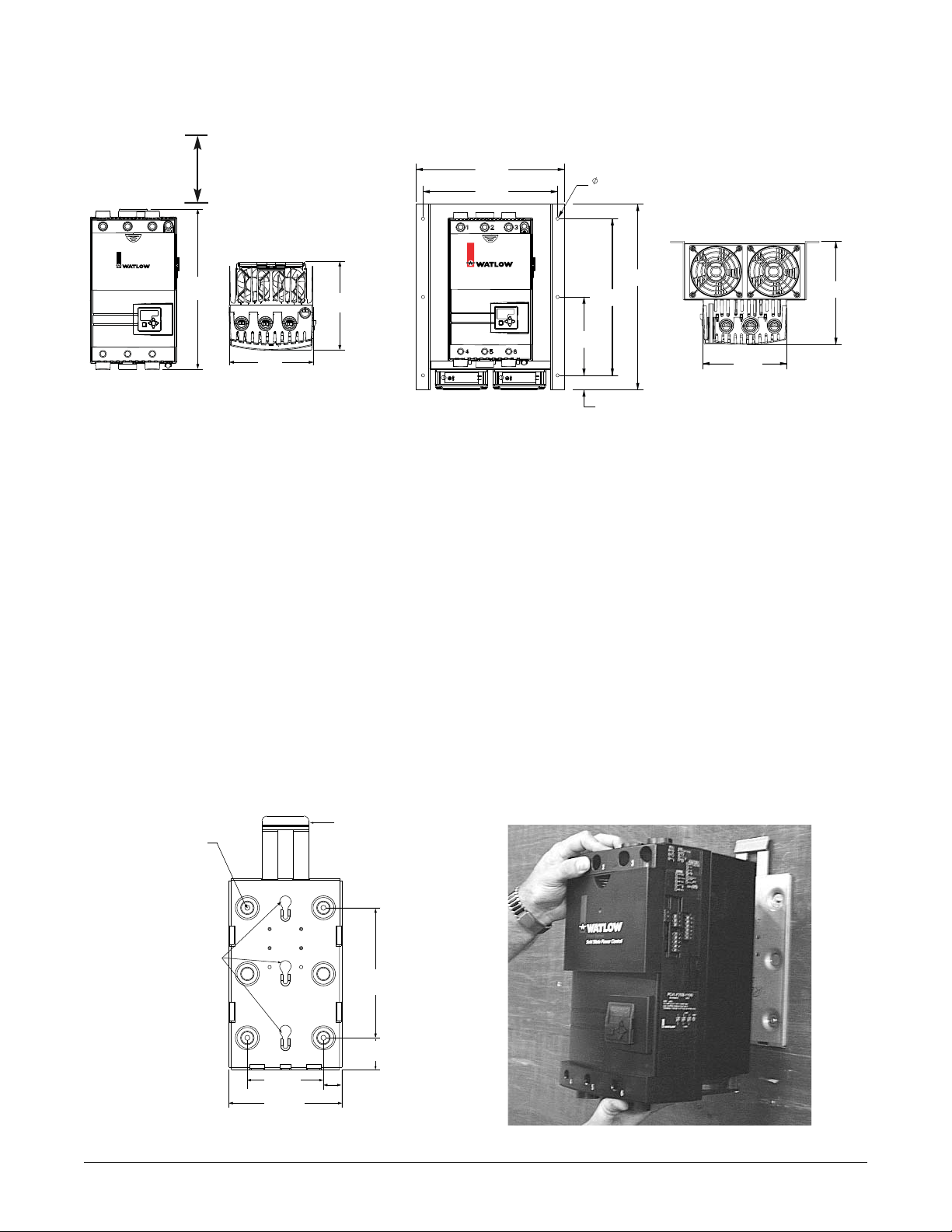
NOTE: The Power Series controller must be mounted vertically. When multiple units are used in one cabinet, it is
best that they are mounted side-by-side when possible. If they are mounted one above the other, adequate spacing
and airflow must be provided. See Enclosure Guidelines on page 2.3.
For models N20 through F30:
1. Determine the panel location for mounting the Power Series controller and punch or drill holes for the
4 mounting screws per the drawing below. The mounting plate can be used as a template.
2. Attach the Power Series mounting plate using 4 screws (customer supplied, #10 screw minimum, 1/4
inch screw maximum).
3. Align the heads of the shoulder screws on the back of the Power Series heat sink with the key slots on
the mounting plate. Push the unit in, and then down until it snaps into place. Mounting is complete.
For F35 models:
F35 models are a bolt-down package. Drill and tap six holes per the above drawing for 1/4-inch 20 bolts.
Figure 2.2b — Mounting plate dimensions. Figure 2.2c — Installing the controller.
Figure 2.2a — Power Series dimensions.
Power Series Dimensions
Add a 9-in. clearance dimension to help develop the
chimney cooling effect. This
should be on the top and
bottom of the Power Series
mounting.
P
s
S
l
Figure 2.2aa — F35 model only.
Power Series Front View
23
1
Power Series
Solid State Power Control
45 6
Power Series Top View
354 mm
(14.0 in.)
191 mm
(7.5 in.)
200 mm
(7.9 in.)
337 mm
(13.3 in.)
305 mm
(12.0 in.)
ower Serie
olid State Power Contro
178 mm
(7.0 in.)
7.1 mm
(0.28 in.)
356 mm
(14.0 in.)
33 mm
(1.3 in.)
421 mm
(16.6 in.)
191 mm
(7.5 in)
234.1 mm
(9.2 in.)
Mounting Holes (4)
Power Series Mounting Plate
7mm
(0.27 in.)
Key Slots
102mm
(4.00 in.)
151mm
(5.93 in.)
Release Tab
178mm
(7.00 in.)
39mm
(1.53 in.)
25mm
(0.97 in.)
Page 9

Installation, Chapter 2 Watlow Power Series ■ 2.3
Enclosure Guidelines
The Power Series must be mounted in a suitable electrical enclosure. It must
have adequate wire bending space and cooling. The maximum ambient
temperature in the enclosure must not exceed 50°C (122°F) for name plate
rating. For other output ratings and enclosure ambient temperatures, see output
rating curves on pages 2.5 and 2.6.
To maintain the proper cooling, the enclosure must be large enough to dissipate
the heat generated by the Power Series, or there must be some form of active
cooling.
1. Air circulation — fans bring air into the bottom of the enclosure and louver
plates to allow the air to exit the top of the enclosure. Filters are not
recommended as they can become plugged and block air flow. To maintain
80 percent of the CFM of a fan, the outlet must be four times the area of the
fan inlet. Ensure that each Power Series is within an unobstructed
airstream.
2. Vortex coolers operate on compressed air and provide good cooling on a
sealed enclosure, but are noisy and consume a lot of air.
3. Cabinet air conditioners work well on sealed enclosures.
4. Heat pipe coolers work well on sealed enclosures, but do not provide as
much cooling as vortex coolers or air conditioners.
To determine how much cooling is required:
1. Determine the amperage load on the Power Series. Multiply the amperage by
1.2 and then by the number of phases controlled. This is the output power
dissipated by the SCRs in watts. Add the watts dissipated by the controller’s
power supply (21W) and multiply the total power in watts by 3.41 to get
BTUs per hour. Vortex coolers, heat pipe coolers, and air conditioner cooling are
rated in BTUs removed.
2. Add up the watts generated by other electronics in the enclosure and
multiply by 3.41 to get BTUs per hour.
3. Add up the total BTUs inside the enclosure and pick a cooling device that will
remove that amount of BTUs.
4. For fan cooled enclosures, enclosure and fan manufacturers usually have
free software programs and application notes to help size the fans for
enclosures. If necessary, contact the Application Engineers at Watlow
Controls for assistance.
Harsh Environment
The Power Series meets standards UL508, Pollution degree 3 for safety which
states: “Conductive pollution occurs or non-conductive pollution occurs which
becomes conductive due to condensation which is to be expected.” However,
Watlow recommends that the Power Series be used in a clean, dry environment
to ensure long-term reliability.
Page 10
2.4 I Watlow Power Series Installation, Chapter 2
Removing the Power Series
Controller
1. To release the Power Series controller from the mounting plate, press in on
the release tab at the top of the mounting plate.
2. When the release tab is in, push up on the controller from the bottom to
release it from the mounting plate. Beware of sharp edges on the heat
sink when you push upward. This will take some force!
3. The F35 model does not use the standard mounting plate. See page 2.2 for
mounting instructions. To remove: reverse the mounting operation.
Maintaining the Power Series
• Cleaning: The heatsink fins must be kept clean for proper cooling and the
printed circuit board should be free of conductive residue condensation.
• Calibration: Not normally necessary. See pages 6.15-6.16 for data restore
and backup.
• Retorquing: See page 3.1 for torque guidelines.
• Software backup and refresh: Not necessary; see page A.7, Power Series
Backup.
NOTE: All Power Series controllers have been 100 percent tested before shipment. The
records of these tests are on file for recall if necessary.
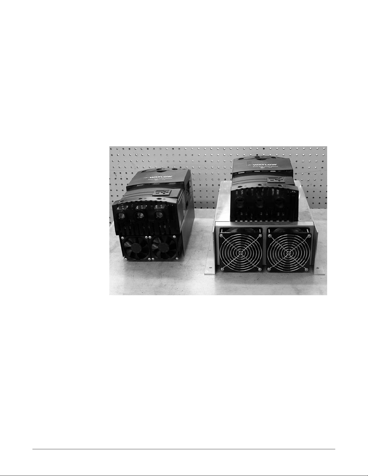
Figure 2.4 — The F35 Power Series (right) is cooled with larger fans.
ç
CAUTION:
You may want to use a
large screwdriver to
press in on the release
tab while you are pushing
on the controller to avoid
potential injury to your
hands.
Page 11
Power Series Output Rating Curves
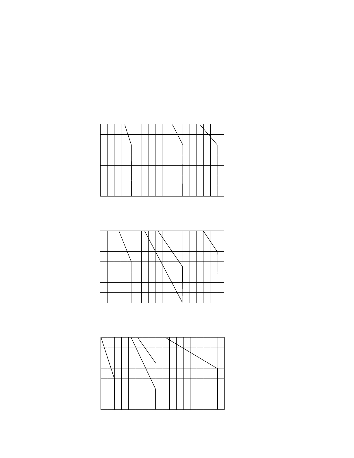
Fan Cooled
All curves are at 100% on with 90°C rated load wire and line wire connected. Note that each
chart is slightly different on the amperage scale. The safe operating region is from 1 amp up
to the specific curve for the output amperage code selected. For example: F25 Single-Phase is
rated up to 200 amps at 50°C; F30 Single-Phase is rated for 250 amps at 50°C. See page 2.6
for Natural Convection Cooled output rating curves.
Watlow Power Series Installation I 2.5
60
55
50
45
Single-Phase Fan Cooled at 100% On
Enclosure Internal
Enclosure Internal
40
35
Ambient Temperature in °C
30
25
8090100
60
55
50
45
40
35
Ambient Temperature in °C
30
25
8090100
60
F20
110
130
120
Current (amps) into a Resistive Load
3-Phase, 2-Leg and 2-Zone Multizone
F20
110
120
Current (amps) into a Resistive Load
3-Phase, 3-Leg and 3-Zone Multizone
150
140
160
Fan Cooled at 100% On
130
150
140
160
Fan Cooled at 100% On
170
170
180
180
F25
190
190
210
200
220
F30F25 F35
210
200
220
230
230
F30
240
240
250
250
260
260
55
50
45
150
160
F30F25
F35
170
190
210
230
180
200
220
240
250
260
Enclosure Internal
40
35
Ambient Temperature in °C
30
25
8090100
F20
110
130
120
140
Current (amps) into a Resistive Load
Page 12
Power Series Output Rating Curves
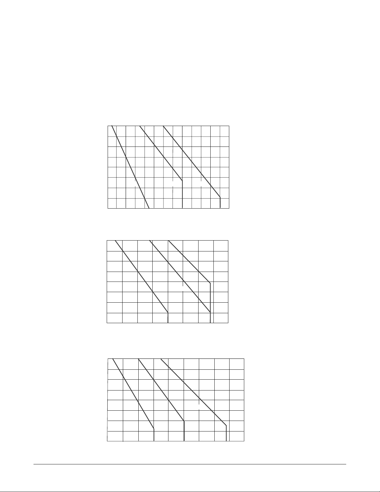
Natural Convection
All curves are at 100% on and with 90°C rated load wire and line wire connected. Note that each chart is
slightly different on the amperage scale. The safe operating region is from 1 amp up to the specific curve for
the output amperage code selected. For example: N25 Single Phase is rated up to 140 amps at 50°C; N30
Single Phase is rated for 165 amps at 50°C.
3 Phase, 3-Leg and 3-Zone Multizone
Natural Convection at 100% On
25
30
35
40
45
50
55
60
65
Current (Amps) into a Resistive Load
N20 N25 N30
Enclosure Internal
Ambient Temperature °C
60 14070 80 90 100 110 120 13050
3 Phase, 2-Leg and 2-Zone Multizone
Natural Convection at 100% On
25
30
35
40
45
50
55
60
65
Current (Amps) into a Resistive Load
60 14070 80 90 100 110 120 130
N20 N25 N30
Enclosure Internal
Ambient Temperature °C
Single Phase Natural Convection at 100% On
25
30
35
40
45
50
55
60
65
Current (Amps) into a Resistive Load
80 21090 100 110 120 130 140 150 170 180 190 200160
N20 N25 N30
Enclosure Internal
Ambient Temperature °C
2.6 ■ Installation Watlow Power Series
Page 13
Terminals 1 - 6
and Ground Lug
Torque to
180 in.-lbs.
(20 Nm.)
with 3/8 inch
Allen wrench
provided.
Strip wires
1-1/8 inch (30mm)
#3 Phillips
Screws for Fuse
Mounting
For models
PXX-F20X-XXXX
PXX-N20X-XXXX
Torque to
26 in.-lbs. (2.93 Nm.)
For models
PXX-F25X-XXXX
PXX-N25X-XXXX
PXX-F30X-XXXX
PXX-N30X-XXXX
PXX-F35X-XXXX
Torque to
44 in.-lbs. (4.95 Nm.)
5/16 inch Bolts
for Fuse Mounting
Torque to 44 in.-lbs.
(4.95 Nm.)
Strip wires
0.24 in. (6mm)
Torque to 8 in.-lbs. (0.9 Nm.) using
a 1/8 inch (2.5 mm) blade screwdriver.
Accepts 12-22 AWG or 2 No. 22-18
AWG wires.
Controller Connectors
Allen Wrench
(Flat surface must be against the case.)
Fuse
Fuse
Fuse
Power Series
Solid State Power Control
3
Chapter Three
Wiring
Wiring the Power Series Controller
Wiring options depend on the model number. Check the terminal designation stickers on the
right side of the controller and compare your model number to those shown here and with
the model number breakdown in the Appendix (page A.10) of this manual.
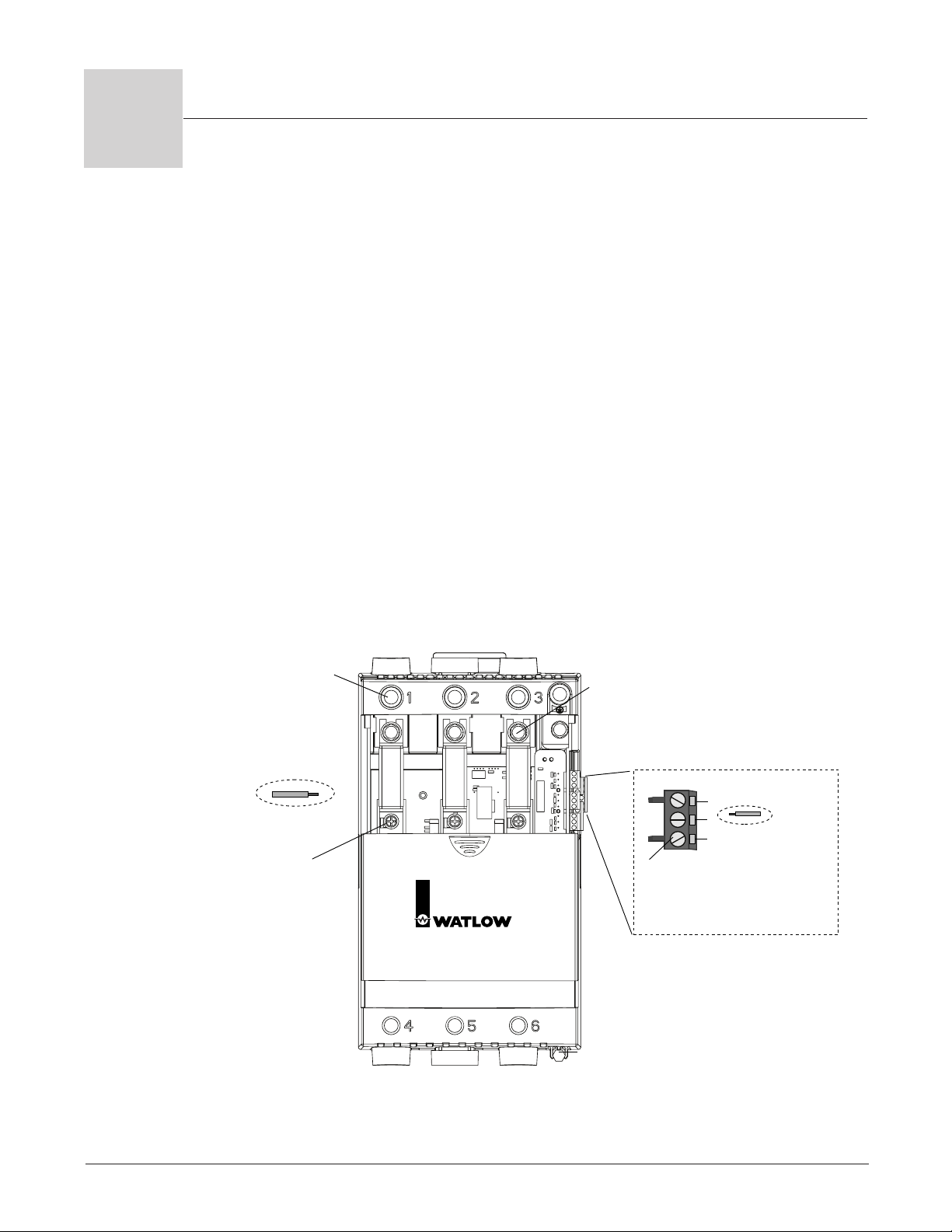
Chapter 3 illustrates how to wire the inputs and outputs for all options. Refer to Figure 3.1
for terminal torque guidelines.
Torque Guidelines
• Properly torque terminals by holding for 30 seconds to allow for wires to settle and
minimize loosening due to cold flow.
• Re-torque all terminals after 48 hours.
• Establish a maintenance program to re-torque line and load terminations every 3-6
months.
Wi r ing , C h apt e r 3 Wat l ow Pow er S e rie s I 3 .1
Figure 3.1 — Torque and wire stripping.
Page 14
3.2 ■ Watlow Power Series Wiring, Chapter 3
ç∫
WARNING:
To avoid damage to
property and equipment,
and/or injury or loss of
life, use National Electric
Code (NEC) standard
wiring practices to install
and operate the Power
Series. Failure to do so
could result in damage,
and/or injury or death.
NOTE:
Input, retransmit and
communications external
terminals have been
designed for protection in
case of direct contact in
accordance with Europpean Standard EN50178.
NOTE:
Insure ground is wired
with the same size wire
as line and load
connections to a ground
of sufficient current
carrying capacity. (Refer
to Chapter 2, p. 2.1,
Power Series Wire
Bending Radius at Base
Current and Ambient
Temperature Rating.)
NOTE:
Torque and wire strip
guidelines:
• Control wiring 1 thru
23.
• Strip wire to 0.24 inch
(6mm). Torque to 8 in.lbs. ( 0.9 Nm).
• Hold torque for 30
seconds to allow for
wiring settling and cold
flow. Re-torque after
48 hours.
• All line connections
should be re-torqued
every 3-6 months.
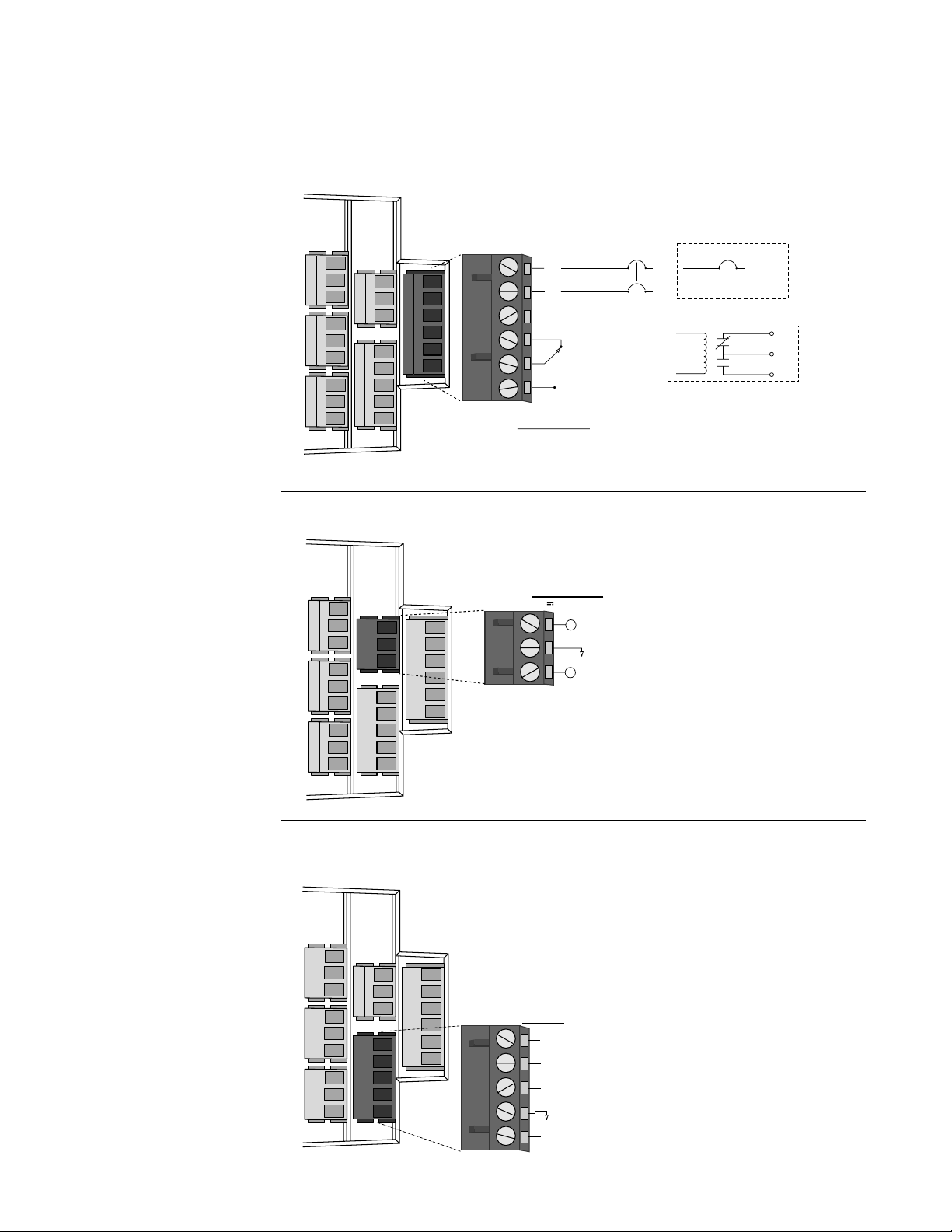
Input Wiring
Figure 3.2a – Control Power and Alarm Wiring
Figure 3.2b – Retransmit Wiring
Figure 3.2c – Communications Wiring
Power Series
6
5
4
3
2
1
11
10
9
8
7
14
13
12
17
16
15
20
19
18
23
22
21
External Connector
COMMS
7 8
485 T/R +
(Common)
9 10 11
232 TRAN (EIA/TIA-232 Transmit Out)
232 REC (EIA/TIA-232 Receive In)
485 T/R -
RETRANSMIT
DC 10V/20mA
Power Series
6
5
4
3
2
1
11
10
9
8
7
14
13
12
17
16
15
20
19
18
23
22
21
External Connector
12 13 14
I
V
+
+
(Current Out, 4 to 20mA)
(Common)
(Voltage Out, 0 to 10V)
Power Series
External Connector
Relay Internal to Power Series
NC
C
NO
L1
L2
L1
L2
208 or 240V~
(Alarm Common)
(Alarm
Normally Open)
(Alarm
Normally Closed)
Unused
120V~
6
5
4
3
2
1
11
10
9
8
7
14
13
12
17
16
15
20
19
18
23
22
21
CONTROLLER
POWER SUPPLY
85 to 265V~ 55VA
L1
Neutral
ALARM
250V~ 3A
1 2 3 4 5 6
Page 15
Wiring, Chapter 3 Watlow Power Series ■ 3.3
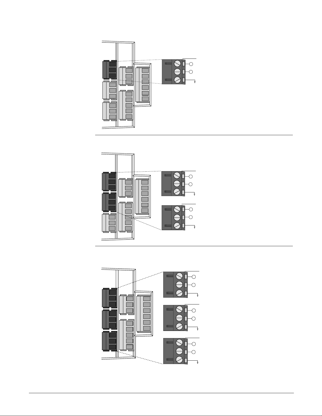
Figure 3.3a – Single Zone Input Wiring
Figure 3.3b – 2-Zone Input Wiring
Figure 3.3c – 3-Zone Input Wiring
Power Series
6
5
4
3
2
1
11
10
9
8
7
14
13
12
17
16
15
20
19
18
23
22
21
External Connectors
21 22 23
INPUT 1
18 19 20
INPUT 2
15 16 17
INPUT 3
I
V
+
+
(Current In, 4 to 20mA)
(Common)
(Voltage In, 0 to 10V)
I
V
+
+
(Current In, 4 to 20mA)
(Common)
(Voltage In, 0 to 10V)
I
V
+
+
(Current In, 4 to 20mA)
(Common)
(Voltage In, 0 to 10V)
NOTE:
Successful installation
requires four steps:
• Choose the controller’s
hardware configuration
and model number
(Appendix);
• Install the controller
(Chapter Two);
• Wire the controller
(Chapter Three); and
• Configure the controller
(Chapters Four, Five
and Six).
ç∫
WARNING:
To avoid damage to
property and equipment,
and/or injury or loss of
life, use National Electric
Code (NEC) standard
wiring practices to install
and operate the Power
Series. Failure to do so
could result in damage,
and/or injury or death.
Power Series
External Connector
INPUT 1
+
(Voltage In, 0 to 10V)
23
22
21
20
19
18
17
16
15
14
13
12
11
10
9
8
7
6
5
4
3
2
1
V
+
(Current In, 4 to 20mA)
I
21 22 23
(Common)
Power Series
External Connectors
INPUT 1
23
22
21
20
19
18
17
16
15
14
13
12
11
10
9
8
7
6
5
4
3
2
1
21 22 23
INPUT 2
18 19 20
+
(Voltage In, 0 to 10V)
V
+
(Current In, 4 to 20mA)
I
(Common)
+
(Voltage In, 0 to 10V)
V
+
(Current In, 4to 20mA)
I
(Common)
Page 16

3.4 ■ Watlow Power Series Wiring, Chapter 3
Line Power/Output Wiring
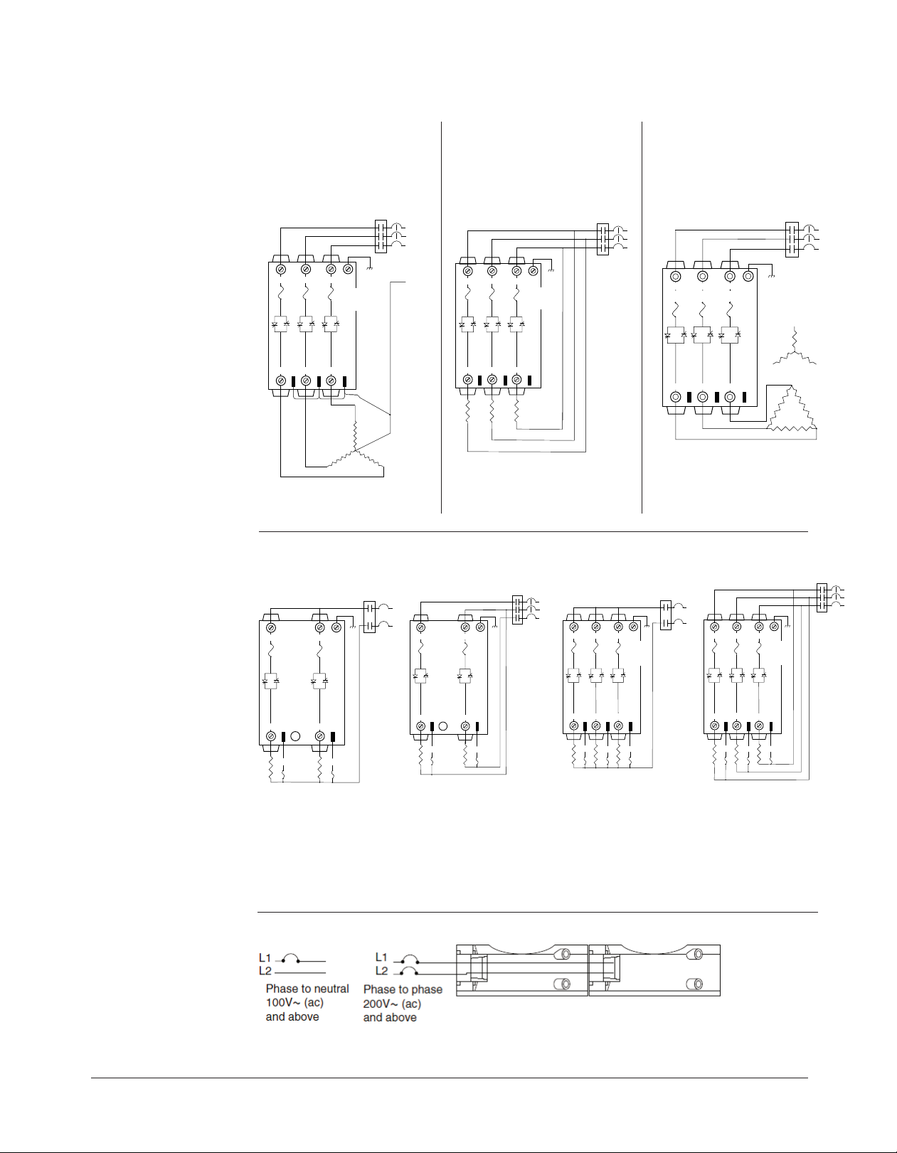
Figure 3.4a – Single Phase Output Wiring
(Model PC1X-XXXX-XXXX)
Figure 3.4b – 3 Phase, 2-Leg, 4 SCR Output Wiring
(Model PC2X-XXXX-XXXX)
NOTE: Our illustrations illustrate circuit breakers for branch circuit protection. Fuses can
also be used.
NOTE:
Successful installation
requires four steps:
• Choose the controller’s
hardware configuration
and model number
(Appendix);
• Install the controller
(Chapter Two);
• Wire the controller
(Chapter Three); and
• Configure the controller
(Chapters Four, Five
and Six).
ç∫
WARNING:
To avoid damage to
property and equipment,
and/or injury or loss of
life, use National Electric
Code (NEC) standard
wiring practices to install
and operate the Power
Series. Failure to do so
could result in damage,
and/or injury or death.
NOTE:
Torque and wire strip
guidelines:
• Connections 1 thru 6,
and ground lug
• Strip wire 1-1/8 in.
(30mm). Torque to 180
in.-lbs. (20 Nm).
• Hold torque for 30
seconds to allow for
wiring settling and cold
flow. Re-torque after
48 hours.
• All load connections
should be re-torqued
every 3-6 months.
çCAUTION: Figure 3.4a shows the
Watlow-recommended output wiring
using the internal bussbar as a
return current path and with ref. 2
not connected. Should a user choose
a non-recommended wiring scheme,
then ref. 2 or the internal bussbar
must be connected to the
appropriate line or neutral. Failure
to follow these guidelines could
cause damage to the Power Series.
çCAUTION: Figure 3.4b shows the
Watlow-recommended output wiring
using the internal bussbar as a
return current path and with ref. 1
and 3 not connected. Should a user
choose a non-recommended wiring
scheme, then ref. 1 or ref. 3 or the
internal bussbar must be connected
to the appropriate line. Failure to
follow these guidelines could cause
damage to the Power Series.
L1
L2
Contacts
Heater
5
120V~
and 277V~
L1
L2
L3
6
L1
Neutral
4
240V~
and above
Limit Control Contacts
(If Required)
1 3
On-board
Semiconductor
Fuse
4 5 6
2
Heater
Gnd
Internal Bussbar
ref.2
Limit Control
2
1 3
On-board
Semiconductor
Fuses
Internal Bussbar
4 5 6
ref.1 ref.3
Gnd
(If Required)
Page 17
L2
L1
L3
4
5
6
Limit Control
Contacts
(If Required)
Heater
2
Gnd
1 3
4 5 6
On-board
Semiconductor Fuses
L2
L1
L3
Limit Control
Contacts
(If Required)
Gnd
On-board
Semiconductor
Fuses
ref.1 ref. 2 ref. 3
PC9
2
13
45
6
N
Limit Control
Contacts
(If Required)
L2
L1
L3
2
Gnd
1 3
4 5 6
On-board
Semiconductor
Fuses
ref.1 ref. 2 ref. 3
ç∫
Limit Control
Contacts
(if required)
L1
L2
Gnd
13
4
6
PC8
On-board
Semi-
conductor
Fuses
2 Independent,
Single-phase Heaters
heater 2
ref.1 ref. 3
heater 1
Limit Control
Contacts
(if required)
L2
L1
L3
Gnd
13
4
6
PC8
On-board
Semi-
conductor
Fuses
2 Independent,
Single-phase Heaters
heater 2
ref.1 ref. 3
heater 1
Gnd
On-board
Semi-
conductor
Fuses
2
13
PC9
4
5
6
ref.1 ref. 2 ref. 3
heater
1
heater
3
heater
2
3 Independent,
Single-phase Heaters
Limit Control
Contacts
(if required)
L1
L2
Limit Control
Contacts
(if required)
L2
L1
L3
Gnd
On-board
Semi-
conductor
Fuses
2
13
PC9
4
5
6
ref.1 ref. 2 ref. 3
heater
1
heater
3
heater
2
3 Independent,
Single-phase Heaters
WARNING:
To avoid damage to
property and equipment,
and/or injury or loss of
life, use National Electric
Code (NEC) standard
wiring practices to install
and operate the Power
Series. Failure to do so
could result in damage,
and/or injury or death.
ç
WARNING:
Install high or low
temperature limit control
protection in systems
where an over
temperature fault
condition could present a
fire hazard or other
hazard. Failure to install
temperature limit control
protection where a
potential hazard exists
could result in damage to
equipment, property and
injury to personnel.
Figure 3.5a – 3-Phase, 3-Leg,
6-SCR Output Wiring for
Figure 3.5b – 3-Phase, 3-Leg,
6-SCR Inside Delta
4-Wire Wye Application
(Model PC4X-XXXX-XXXX)
Note: 1. Phasing must be as shown.
2. Do not connect Ref. terminals.
Figure 3.5d – **Multizone Output Wiring
Figure 3.5c – 3 Phase, 3-Leg,
6-SCR Output Wiring
(Model PC3X-XXXX-XXXX)
Note:
Wiring must
be A, B, C
rotation.
çCAUTION: Do not connect ref.
connections with PC3 models. Failure
to follow this guideline could cause
damage to the Power Series.
NOTE:
For reference
connections 1 to 3, use
QC 0.250 in. wide and
0.032 in. thick
compatible connection
which is fully insulated
with nylon and has a
metal grip ring.
For 14-16 AWG:
Molex/ETC AA-5261; 3M
MNG14-250DFIX C-54503X or equivalent.
**NOTE: Models PC8 and PC9 control legs are isolated so that they may be wired from phase-to-phase inside delta or
PC8X-XXXX-XXX1
Molex/ETC AA-5261; 3M
MNG14-250DFIX
C-54-503X or equivalent.
Figure 3.5e – Fan Wiring for 250A Models
PC8X-XXXX-XXX3 PC9X-XXXX-XXX1
Note: Wiring must be A,
B, C rotation if phase
control is selected.
PC9X-XXXX-XXX3
Note: Wiring must be A,
B, C rotation if phase
control is selected.
phase-to-neutral, independent of how the other legs are wired.
Wi r ing , Cha p ter 3 Wat l ow P o wer S eri e s I 3. 5
Page 18
3.6 I Watlow Power Series Wiring, Chapter 3
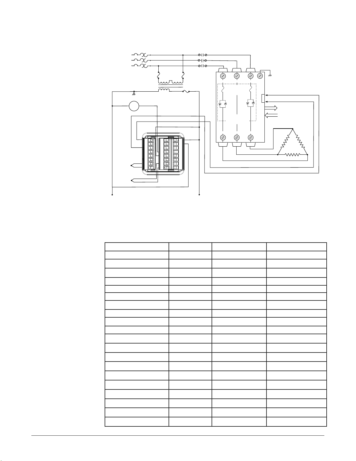
Wiring Example
Figure 3.6 - System wiring example.
Recommended fusing options to meet 200KA SCCR. All other untested combinations are
defaulted to 5KA per UL508A and NEC guidelines.
ç∫
WARNING:
To avoid damage to
property and equipment,
and/or injury or loss of
life, use National Electric
Code (NEC) standard
wiring practices to install
and operate the Power
Series. Failure to do so
could result in damage,
and/or injury or death.
ç
WARNING:
Install high or low
temperature limit control
protection in systems
where an over
temperature fault
condition could present a
fire hazard or other
hazard. Failure to install
temperature limit control
protection where a
potential hazard exists
could result in damage to
equipment, property and
injury to personnel.
NOTE: Our wiring
example illustrates
circuit breakers for
branch circuit protection.
Fuses can also be used.
Power Series Model Fuse Rating Watlow Fuse P/N Bussmann Fuse P/N
PC1X-N20 160 0808-0102-0160 170M1319
PC1X-N25 200 0808-0102-0200 170M1320
PC1X-N30 250 0808-0102-0250 170M1321
PC1X-F20 160 0808-0102-0160 170M1319
PC1X-F25 250 0808-0102-0250 170M1321
PC1X-F30 315 0808-0102-0315 170M1322
PC2(8)X-N20 125 0808-0102-0125 170M1318
PC2(8)X-N25 160 0808-0102-0160 170M1319
PC2(8)X-N30 160 0808-0102-0160 170M1319
PC2(8)X-F20 160 0808-0102-0160 170M1319
PC2(8)X-F25 250 0808-0102-0250 170M1321
PC2(8)X-F30 250 0808-0102-0250 170M1321
PC3(4,9)X-F35 315 0808-0102-0315 170M1322
PC2(8)X-F35 315 0808-0102-0315 170M1322
PC3(4,9)X-N20 100 0808-0102-0100 170M1317
PC3(4,9)X-N25 125 0808-0102-0125 170M1318
PC3(4,9)X-N30 160 0808-0102-0160 170M1319
PC3(4,9)X-F20 125 0808-0102-0125 170M1318
PC3(4,9)X-F25 200 0808-0102-0200 170M1320
PC3(4,9)X-F30 200 0808-0102-0200 170M1320
L3
480V~
L2
(ac)
L1
Breaker
480V~ (ac)
120V~ (ac)
CRI
Coil
PM6C2FA-ALAJAAA
–
Control
Thermocouple
F1
G1
+
H1
L4
K4
T1
T2
S1
S2
R1
R2
98
99
CC
CA
CB
B5
D6
D5
CRI: High
Limit
Contactor
213
On-board
Semiconductor
Fuses
3Ø, 2-leg
Zero Cross Fired
Power Series
456
Gnd
+
4 to 20mA
–
Retransmit to Monitor
Output Operation
Control Power
Three-phase
Resistive Heater
High Limit
Thermocouple
AC Common AC High
Page 19
Chapter Four
Navigation and Software
Keys and Displays
This chapter explains keys, displays and navigation skills. You’ll also find a complete
software map.
Navigation and Software, Chapter 4 Watlow Power Series ■ 4.1
4
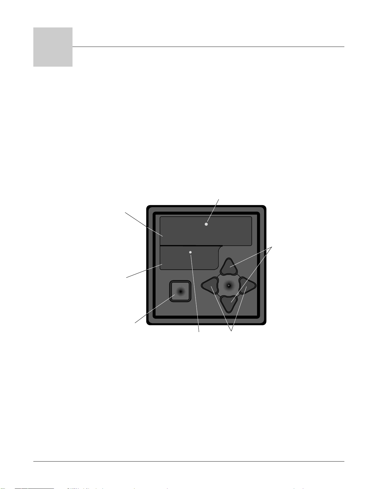
Figure 4.1 — Power Series keys and displays.
Alarm Indication LED:
Lit when an alarm is
active.
Upper Display:
Indicates operating
levels - requested
current, line voltage or
power feedback levels
for the parameter in the
lower display.
Lower Display:
Indicates the
parameter whose
value appears in the
upper display.
***8
***8
Increment/Decrement
Keys: Moves to next or
previous submenu if at
the top item of a menu, or
increments/decrements
current menu item.
Home Key:
Returns to the Display
Loop if in any other
page or menu, or in
the Display Loop,
moves between like
prompts of different
zones or phases.
Small LED:
Blinks with
communications
activity.
Left/Right Keys: Moves
to the next or previous
item in a submenu.
Page 20
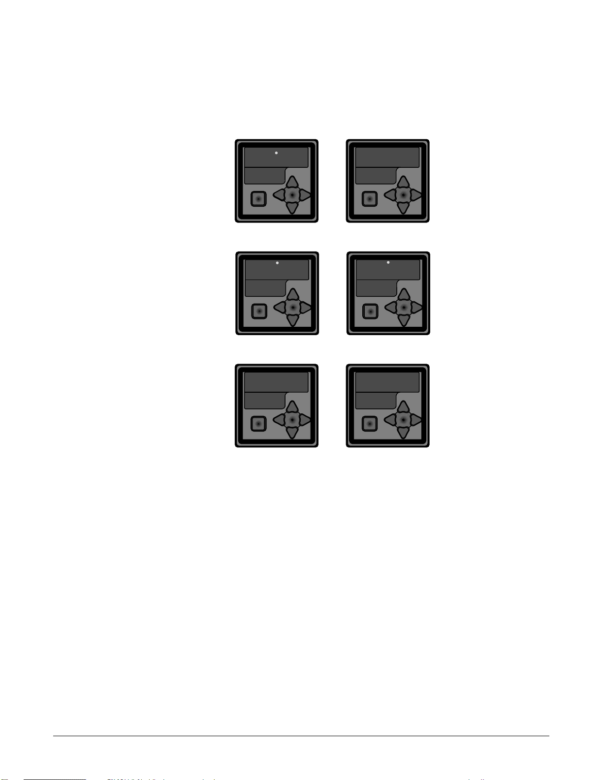
Navigating the Power Series
Choose a page (Setup or Factory) and press its key sequence. The page appears in the lower
display.
PressÎ or Ó to find a specific menu in a page. The menu appears in the upper display and
the page remains in the lower display.
Press ® to enter the list of parameters in the menu displayed. The menu’s parameters
appear in the lower display and the values in the upper display. To go backward through the
parameter list press ¬ .
PressÎ or Ó to select a value, either alpha or numeric, within a specific parameter.
Setup Page - for
setting up the
control, alarms,
retransmit, and
communications.
Factory Page for calibration
and diagnostic
information.
Display Loop for monitoring
parameters and
adjusting manual/digital input,
and for clearing
alarms if they are
latched.
4.2 ■ Watlow Power Series Navigation and Software, Chapter 4
NOTE:
The Load Activity Indicator in the Display Loop indicates different things, dependent on whether heater
diagnostics is installed. With heater diagnostics installed, it indicates load current has been detected.
Without heater diagnostics installed, it indicates the SCRs are being gated and line voltage is present.
• Setup Page: From Display Loop, press ± and ¬ keys together for 2 sec.
• Factory Page:
• Display Loop: From Setup or Factory Page, press the ± key.
***8
***8
***8
***8
From Setup Page, press ± and ¬ and ® keys together for 2 sec
***8
***8
algo
SEt
***8
FCty
-–-
load
Page 21
Navigation
¨[````]¨[````]¨[load]¨[freq]¨
Single-Zone Single-Phase
¬®[In``] or [In|c] or [In|u] ¬®[`Out]¬®[`Hbt]¬%%% ®[`UoL]¬®[`Cur]¬®[`HUa]
Multi-Zone [```] Three-Phase [```]
%%%% [2one]
%%%%%%% [PHAS]
Display Loop
Use the Increment/Decrement keys ( Ó Î ) to select a Zone or Phase
within the Display Loop. The Zone/Phase appears in the upper display.
Use the Left/Right arrow keys ( ¬ ® ) to select a parameter within a Zone or Phase.
The parameter appears in the bottom display.
Use the Increment/Decrement keys (
Ó Î ) to select a value, either alpha or
numeric, within a parameter. The value appears in the upper display.
Use the Home key ( ± ) to toggle between Zones/Phase 1, 2, or 3 sequentially.
(#)
Î
Ó
Display Zone
Selection
Display Phase
Selection
(#)
Î
Ó
(code) (code)
Active Alarms
(if any)
[```1] Zone 1 [```1] Phase 1
[2one] % ¨[In1`] or [In|`c1] or [In|`u1] ¨[Out1]¨[Hbt1]¨[UoL1]¨[Cur1]¨[HUa1]¨% [`ph5] % ¨[UoL1]¨[Cur1]¨
%Î% ±% ±% ±% ±% ±% ±% ±% ±% Î% ±% ±%
% Ó%%%%%% Ó%
[```2] Zone 2 [```2] Phase 2
[2one] % ¨[In2`] or [In|`c2] or [In|`u2] ¨[Out2]¨[Hbt2]¨[UoL2]¨[Cur2]¨[HUa2]¨% [`ph5] % ¨[UoL2]¨[Cur2]¨[`HUa]¨
% Î% ±% ±% ±% ±% ±% ±% ±% ±%% Î% ±% ±%
% Ó%%%%%% Ó
[```3] Zone 3 [```3] Phase 3
[2one] % ¨[In3`] or [[In|`c3] or [In|`u3] ¨[Out3]¨[Hbt3]¨[UoL3]¨[Cur3]¨[HUa3]¨% [`ph5] % ¨[UoL3]¨[Cur3]¨
%Î% ±% ±% ±% ±% ±% ±% ±% ±% Î% ±% ±%
% Ó%%%%%% Ó
%
Navigation and Software, Chapter 4 Watlow Power Series ■ 4.3
NOTE: For an explanation of the parameters in the Display Loop, range information, Modbus address, and conditions for
the parameter to appear, see pp. 6.1-6.4, Chapter Six, Parameters.
NOTES:
What you see in each Page and in each Menu are factory set, depending on the options and settings of your controller.
The input signal method indicator will change depending on the input signal method chosen — digital, current, or volts.
Current operating parameters may be modified at any time with the use of the keypad or communications port.
The Display Loop is
used to monitor
parameters and adjust
manual/digital input,
and to clear alarms if
they are latched.
***8
***8
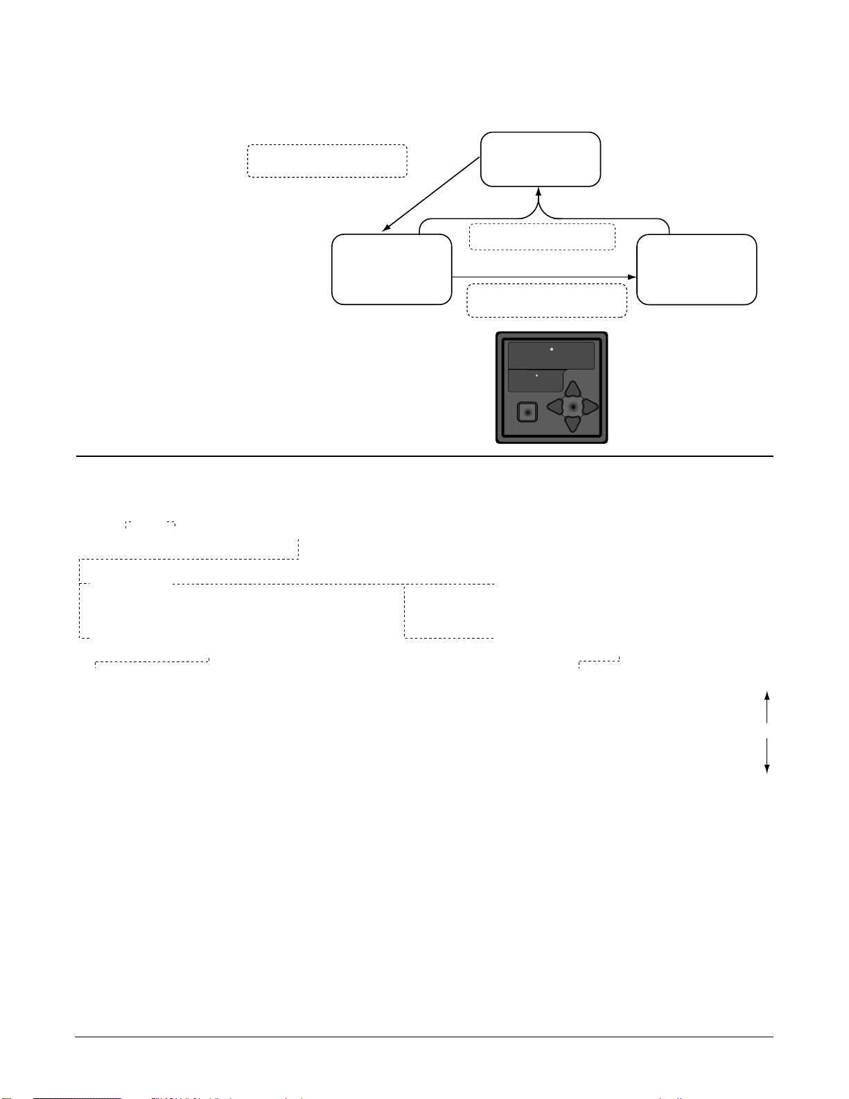
Press Home and Left Keys together
for 2 seconds to enter the Setup
Menus from the Display Loop.
Setup Page Menus
±¬
Display Loop
±±
Press Home Key from any menu to
return to the Display Loop.
% ±¬®
Press Home, Left and Right Keys all
together for 2 seconds to enter the
Factory Menus from the Setup Menus.
Factory Page Menus
Page 22

4.4 ■ Watlow Power Series Navigation and Software, Chapter 4
**NOTE: These menus and display prompts are only viewable in the Factory Mode using a password.
NOTE: For an explanation of the parameters in the Setup Page, (range information, Modbus address, and conditions for the
parameter to appear), see Chapter Six, Parameters, pp. 6.5-6.14; for information on the Factory Page, see pp. 6.14-6.22.
[dAta] System Data Manipulation
[FctY]% ¨[baup]¨[dflt]¨[rEst]¨[nUOl]¨
%Î
%Ó
[`Loc] Global/Menu Lockouts
[[FctY]% ¨[gloc]¨[`Ctr]¨[`OPt]¨[`Alr]¨[COm]¨[retr]¨[`CIn]¨[C|`rtr]¨[dAta]¨[diAg]¨
%Î
%Ó
[InFo] Unit Information
[FctY]% ¬®[`sn–]¬®[`sn_]¬®[date]¬®[HUEr]¬®[SUEr]¬®[sbld]¬®[ratU]¬®[rata]¬®[2onC]¬®[`Opt]¬®[```Ç]¬®
Î
%Ó
%%% ¬®[Hrs_]¬®[Hrs–]¬®[HIÇ`]¬®[sdÇ`]¬®[AlÇ`]
[diAg] Diagnostics
[[FctY]% ¨[``Ad]¨[Cnts]¨[l!A1]¨[l!A2]¨[l!A3]¨[l@A1]¨[l@A2]¨[l@A3]¨[l#A1]¨[l#A2]¨[l#A3]¨
Î
%Ó%
¨[retr]¨[`UAL]¨[``In]¨[dIsp]
%%
[`pw] Factory Password
[FctY]
% ¨[`pw]¨[fcty]¨
%
Î
%Ó
[CIn1] Calibrate Analog Input Signal Zone 1**
[FctY] % ¬®[nnA_]¬®[nnA–]¬®[UoL_]¬®[UoL–]¬®[Cala]¬®
%
Î
%Ó
[CIn2] Calibrate Analog Input Signal Zone 2**
[FctY] % ¬®[nnA_]¬®[nnA–]¬®[UoL_]¬®[UoL–]¬®[Cala]¬®
%
Î
%Ó
[CIn3] Calibrate Analog Input Signal Zone 3**
[FctY] % ¬®[nnA_]¬®[nnA–]¬®[UoL_]¬®[UoL–]¬®[Cala]¬®
%
Î
%Ó
[Crtr] Calibrate Retransmit**
[FctY]% ¬®[nnA_]¬®[nnA–]¬®[UoL_]¬®[UoL–]¬®[Calr]¬®
%Î
Factory Page Menus
Use the Increment/Decrement keys ( Ó Î ) to select a menu
within the Factory Page. The menu appears in the upper display.
Use the Left/Right arrow keys (
¬ ® ) to select a parameter
within a menu. The parameter appears in the bottom display.
Use the Increment/Decrement keys ( Ó Î ) to select a value,
either alpha or numeric, within a parameter. The value appears
in the upper display.
*NOTE: This prompt will only appear in [Ctr1], and if the controller is 3 phase.
Setup Page Menus
[algo] Control Algorithm
[`set]
% ¨[algo]¨[`ftb]¨[``UC]¨
%Î% Î
%Ó% Óv
%
[Ctr1] Setup Control Zone 1
% ¬®[``In]¬®[%dflt]¬®[nna_]¬®[nna–]¬®[Uol_]¬®[Uol–]¬®[lrn|``A]¬®[bl`U]¬®[lrn|``U]¬®[type]¬®[rate]¬®[soft]¬®[rdly]¬®
[`set]
%Î
%Ó
[Opt1] Setup Options Zone 1
[`set]
% ¬®[`Hbo]¬®[Min]¬®[`HbC]¬®[`Cli]¬®[`Cla]¬®[tol_]¬®[toL–]¬®[Indf]¬®[1Cur]¬®
%Î
%Ó
[Ctr2] Setup Control Zone 2
[`set]
% ¬®[``In]¬®[dflt]¬®[nna_]¬®[nna–]¬®[Uol_]¬®[Uol–]¬®[lrn|``A]¬®[bl`U]¬®[lrn|``U]¬®[rate]¬®[soft]¬®
%
Î
%Ó
[Opt2] Setup Options Zone 2
[`set]
% ¬®[`Hbo]¬®[Min]¬®[`HbC]¬®[`Cli]¬®[`Cla]¬®[tol_]¬®[toL–]¬®[Indf]¬®[1Cur]¬®
%Î
%Ó
[Ctr3] Setup Control Zone 3
[`set]
% ¬®[``In]¬®[dflt]¬®[nna_]¬®[nna–]¬®[Uol_]¬®[Uol–]¬®[lrn|A]¬®[bl`U]¬®[lrn|``U]¬®[rate]¬®[soft]¬®
%
Î
%Ó
[Opt3] Setup Options Zone 3
[`set]
% ¬®[`Hbo]¬®[Min]¬®[`HbC]¬®[`Cli]¬®[`Cla]¬®[tol_]¬®[toL–]¬®[Indf]¬®[1Cur]¬®
%Î
%Ó
[`aLr] Setup Alarms Configuration
[`set]
% ¬ ®[A|``l9c]¬®[glbl]¬®[Open]¬®[`tol]¬®[``Ot]¬®[`aLÇ]¬®[Line]¬®[p|bal]¬®[lbal]¬®[ldif]¬®[freq]¬®
%Î
%Ó
% %%% ¨ [C|``wd]¨[``OU]¨[``UC]
[COm] Setup Comms Configuration
[`set]
% ¨[addr]¨[baUd]¨[`wd]¨[`seC]¨[pwr]¨
%Î
%Ó
[retr] Setup Retransmit Configuration
[`set]
% ¬®[`Cfg]¬®[type]¬®[pha5]¬®[2one]¬®[Cur_]¬®[Cur–]¬®[HUa_]¬®[HUa–]¬®[rt|``C_]¬®[rt|``C–]¬ ®[rt|``U_]¬® [rt|``U–]¬ ®
%Î
%Ó
[cont] Î [`OFF] Î [`ftb] Î Urtb] Î [pH2t]
Use the Increment/Decrement keys ( Ó Î ) to select a menu
within the Setup Page. The menu appears in the upper display.
Use the Left/Right arrow keys (
menu. The parameter appears in the bottom display.
Use the Increment/Decrement keys (
or numeric, within a parameter. The value appears in the upper display.
¬ ® ) to select a parameter within a
Ó Î ) to select a value, either alpha
*
Page 23
Chapter Five
Control Methods and Features
Features, Chapter 5 Watlow Power Series ■ 5.1
5
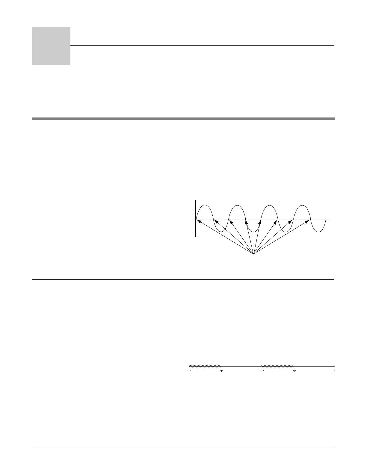
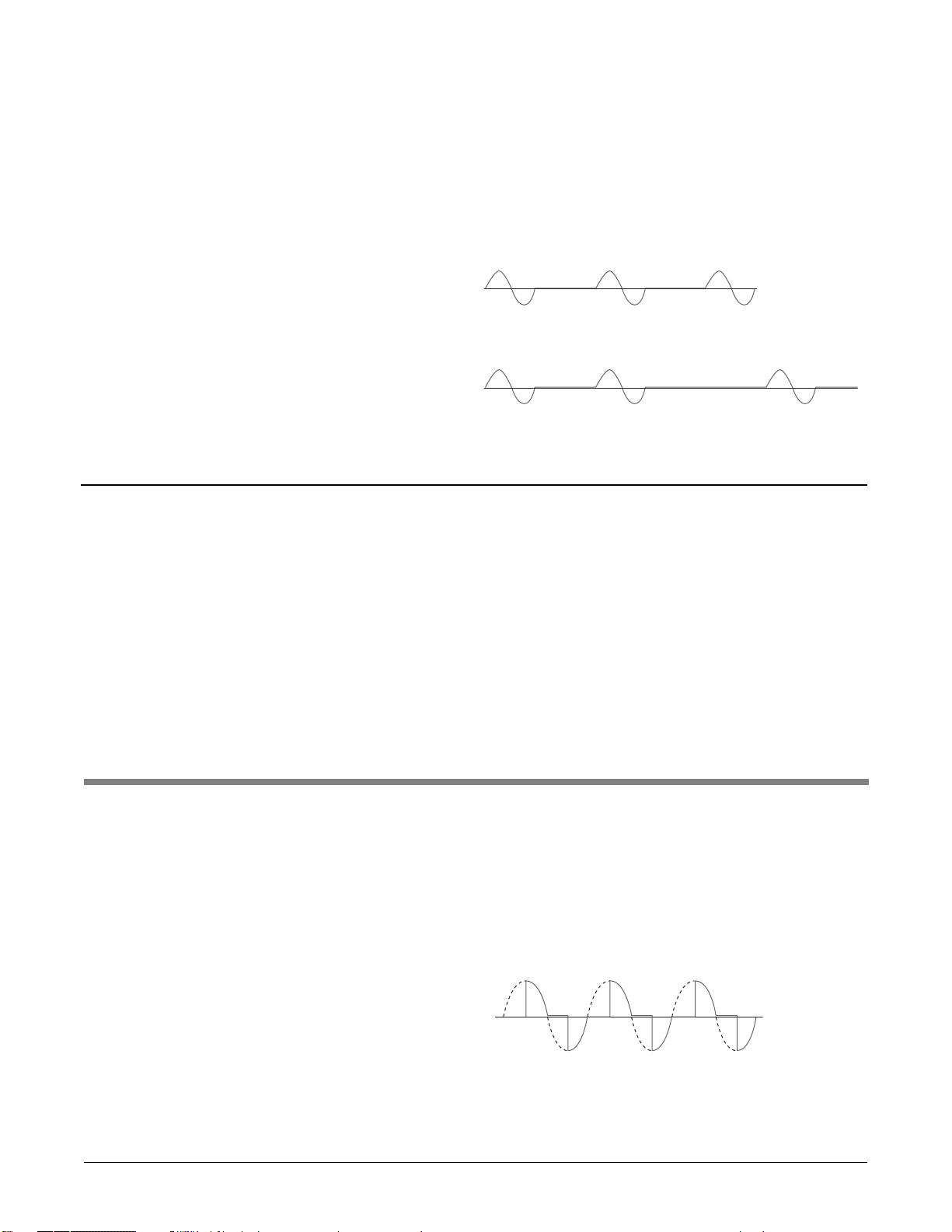
Zero cross (also known as burst firing) provides even
output power with the lowest level of noise generation (RFI). Zero cross is the preferred method for
controlling a resistive load.
The controller determines when the ac sine wave
crosses the 0-volts point, then switches the load,
minimizing RFI.
Zero cross control is available for all Power Series
configurations.
Soft start and current limiting are not available
with zero cross control.
Setup Page:
• Enter the Setup Page by holding ± ¬for 3 seconds.
• When the display reads [algo], press ® until [`Off]
[`set] [Algo]
is displayed. Press Ó Î to select [`ftb] fixed time
base, zero cross or [Urtb] variable time base, zero
cross.
Figure 5.1a — Zero cross switching.
Fixed Time Base - Zero Cross
In the fixed time base control method, the selected
percentage power level output is generated over a
fixed time period (i.e. a fixed number of cycles),
regardless of power level selected. Resolution of operator selectable power may be more precise than the
fixed time base allows. Selected power output level is
rounded to the closest possible power output value in
full cycles as necessary.
Line voltage compensation is not used in the fixed
time base control method.
Setup Page:
• Enter the Setup Page by holding ± ¬for 2 seconds.
• When the display reads [algo], press ® until [`Off]
[`set] [Algo]
is displayed. Press Ó Î to select [`ftb] fixed time
base, zero cross.
• Press ® until [1seC] is displayed.
[`Ftb]
Press Ó Î
to select [1seC] or [4seC].
Figure 5.1b — 40% power, fixed time base, 60 Hz, 1 sec
time base.
Zero Cross
+
0
-
SCR Switch On/Off Points
24 Cycles ON 36 Cycles OFF
24 Cycles ON 36 Cycles OFF
Page 24
5.2 ■ Watlow Power Series Features, Chapter 5
Variable Time Base - Zero Cross
In the variable time base control method, an optimal
ratio of cycles on to cycles off is used to generate the
desired power output. The number of cycles needed
to completely generate a desired power level is
variable in single cycle increments. Line voltage
compensation algorithms are used to adjust the
percentage power output while operating in this
mode. Variable time base operation gives the best
response time and resolution and provides for the
longest heater life.
In single cycle variable time base below 50 percent
power, the unit is never on for more than one consecutive full cycle. Above 50 percent power, the unit is
not off for more than one consecutive full cycle while
maintaining the proper output.
Line voltage compensation is active if selected; however, it can be disabled.
Setup Page:
• Enter the Setup Page by holding ±¬for 2 seconds.
• When the display reads [algo], press ® until [`Off]
[`set] [Algo]
is displayed. Press Ó Î to select [Urtb] variable
time base, zero cross.
Figure 5.2a — 50% variable time base
1 cycle on, 1 cycle off.
Figure 5.2b — 40% single cycle variable time base
1 cycle on, 1 cycle off, 1 cycle on, 2 cycles off.
DC Contactor - Zero Cross
DC contactor control mode is a specialized version of
zero cross control in which the analog control input
is always used and percentage power output is fixed
at 100 percent or 0 percent.
The off/on thresholds are 2.0V/3.5V for voltage
input; 5.0mA/8.0mA for current input. This means
the unit is off for an input voltage (current) of
2.0V(5.0mA) or lower, and 100% on for an input volt-
age (current) of 3.5V(8.0mA) or higher. Maximum
input voltage is 10.0V.
In contactor mode use a four second cycle time to
improve heater diagnostics operation.
Line voltage compensation is not used under dc contactor control, the output is either 100 percent on or
100 percent off.
Setup Page:
• Enter the Setup Page by holding ±¬for 2 seconds.
• When the display reads [algo], press ® until [`Off]
[`set] {Algo]
is displayed. Press ÓÎto select [cont] dc
contactor.
NOTE: Heater Tolerance, Heater Open and Load Balance
alarms do not work in DC Contactor control mode.
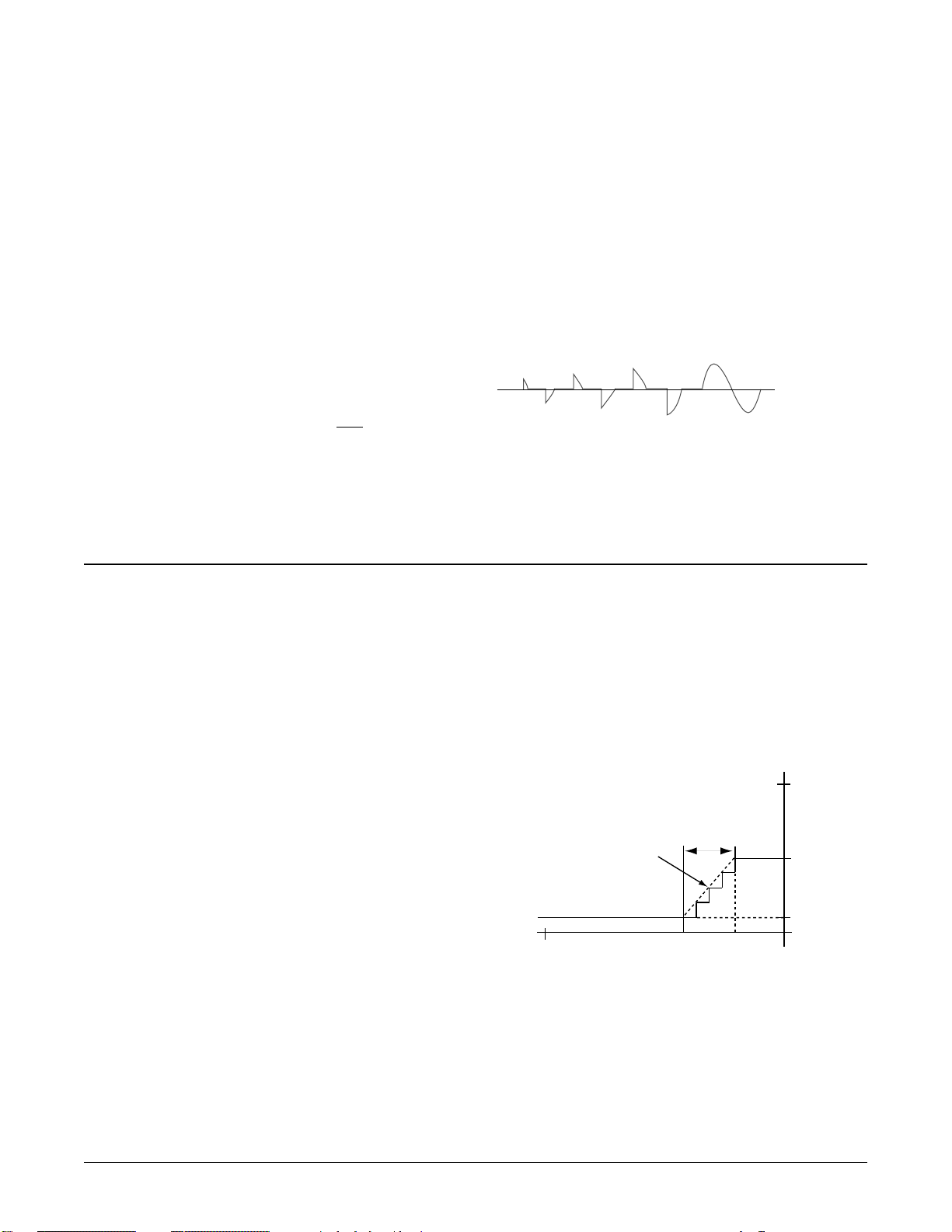
The phase angle control method gates a limited
portion of the line voltage cycle to the load based on
percentage power selected. Soft start is always
included when phase angle is selected.
Phase angle control may not be selected in a 3
phase, 2-leg system.
Line voltage compensation will be used to adjust the
percentage power output while operating in this
mode if selected.
Current limiting is a valid option with phase angle if
the unit is equipped with heater diagnostics.
Setup Page:
• Enter the Setup Page by holding ±¬for 2 seconds.
• When the display reads [algo], press ® until [`Off]
[`set] [Algo]
is displayed. Press Ó Î to select
[PH2t] phase
angle.
Figure 5.2c— Phase angle firing.
NOTE: The maximum output power is 99%. This is considered full on for the Power Series.
Phase Angle
Page 25
Features, Chapter 5 Watlow Power Series ■ 5.3
Soft Start
Soft start is a variation of phase angle control
executed on startup in which there is a gradual
increase in power until the final selected power output is reached. If soft start is selected, the system
will execute the soft start sequence each time a zone
starts active control. This happens at power-on and
on recovery from an alarm such as “Line Loss.” The
soft start time is the time it takes to achieve 100 percent power after a zone restart. The actual time may
be greater than the set time because of the resolution, but the actual time will never be less than the
set time. Rate = 100.0 ÷ time. The actual power
achieved is set by the temperature control input (see
Figure 5.3a and 5.4a).
NOTE: Soft start is intended to be used only
for slowly
increasing power on the initial power request.
Soft start is available in single phase and 3 phase, 3leg models only.
Soft start is always used in systems with phase angle
control mode selected unless
[soft] is set to [```0].
Setup Page:
Adjustable Soft Start - On Power Up
• Enter the Setup Page by holding ± ¬for 2 seconds.
• When the display reads [algo], press Î until [CTr1]
[`set] [`set]
is displayed. Press ®
until [``$0] is displayed.
[soft]
Use the Ó Î keys to set the desired soft start time
in seconds.
NOTE: Repeat this procedure for each zone that you wish to
configure.
Figure 5.3a — Soft start.
Maximum Rate of Change
The maximum rate of change is used during normal
operation of a phase angle controlled system (after
a soft start sequence ends) to cause large changes in
requested power to be implemented gradually. The
maximum rate of change of the power is defined as
the percentage of power change allowed every 0.1 second. This prevents a sudden increase or decrease in
current from one phase angle level to another level
from one cycle to the next into a nonlinear load that
could be damaged or blow a fuse.
Setup Page:
Adjustable Maximum Rate of Change On
Signal Change
• Enter the Setup Page holding ± ¬for 2 seconds.
• When the display reads [algo], press Î until [CTr1]
[`set] [`set]
is displayed. Press ®
until [`1)0] is displayed.
[rate]
Use the Ó Î keys to set the desired % output
change per 0.1 seconds to reach the desired output power level when in phase angle control.
Example:
Time needed for 100% change in power at selected [rate] :
10.0% increase = 1 sec. from 0 to 100% power
10.0% increase = 0.8 sec. from 10 to 90% power
10.0% increase = 0.4 sec. from 10 to 50% power
NOTE: The default for Maximum Rate of Change is set to
10%/0.1 second.
NOTE: Repeat this procedure for each zone that you wish to
configure.
Figure 5.3b — Maximum rate of change set to 10%.
100%
Rate of change
limited by phase
angle maximum
rate of change.
Requested power level changed from 10% to 50% at (time) t1.
Actual power out has changed from 10% to 50% by t2.
0.4
seconds
t1 t2
50%
10%
0%
Page 26

Heater Bakeout
If a system is shut down for long periods, some
heaters can absorb moisture. With a standard power
controller, turning the power full “on” when moisture is present, can cause the fuses or the heater to
blow. However, with the Power Series you can now
“bake out” the moisture in a wet heater before
applying full power and destroying the heater.
During heater bakeout, the Power Series slowly
increases voltage to the heater while monitoring the
output current. If the heater achieves full output
before the bakeout time expires, then the heater is
dry and can be put into service. At all times, the output will not exceed the temperature controller set
point.
If the output current reaches a user-specified trip
point during the bakeout (as it would if arcing
occurred in the heater), then the Power Series shuts
off the output and activates an over-current trip
error, [HbOC]. The operator should then lengthen
the bakeout time and restart or just restart, depending on how long the initial bakeout ran. To start
heater bakeout you must cycle the controller power.
After a successful heater bakeout, the Power Series
automatically switches to the operator pre-selected
control mode (phase angle or zero cross).
NOTE: Heater bakeout is intended for magnesium oxide
filled nichrome elements. A nichrome element heater can
have a tolerance up to ± 10%. This tolerance could add to
the maximum heater current during normal operation. For
example, a 50-amp heater could draw 55 amps and still be
a good and dry heater.
Heater bakeout may be selected in single phase
(phase to neutral) and 3 phase, 6 SCR systems with
any pre-selected control mode. You must also have
the heater diagnostics option installed on your
Power Series.
Heater bakeout operates with an over-current trip.
The operator must set the maximum current
allowed during heater bakeout using the [HbOC]
prompt. This will set the maximum allowable load
during heater bakeout.
Setup Page:
• Enter the Setup Page by holding ± ¬for 2 seconds.
• When the display reads [algo], press Î until [Opt1]
[`set] [`set]
is displayed. Press ®
until [`Off] is displayed.
[`Hbo]
Use the Ó Î keys to turn heater bakeout on.
• Press ®
until [Min] appears in the lower display.
Use the Ó Î keys to set the desired heater bake-
out time in minutes.
• Press ®
until [`HbC] appears in the lower display.
Use the Ó Î keys to set the desired maximum
load current during the heater bakeout process.
NOTE: Repeat this procedure for each zone that you wish to
configure.
Figure 5.4a— Heater bakeout.
100%
60%
0%
Output P
ower
Time
Temperature Control
Command Signal
Process Set Point
5.4 ■ Watlow Power Series Features, Chapter 5
Heater Tolerance Detection
Heater tolerance detection allows you to detect a
failed heater or a heater that is beginning to fail. An
alarm is triggered if the load current drops below or
rises above specific levels.
For example, if you have five heaters that draw 20
amps each, for a total load current of 100 amps at
100 percent power, you could program the heater
tolerance alarm to trigger if the load current drops
below 80 amps at 100 percent power. This would
indicate that one of the heaters has failed (open.)
To monitor for a heater that is beginning to fail or
age, you could watch for too little or too much current. For example, in Figure 5.4b the alarm is programmed to trigger if the load current drops below 90
amps, or rises above 110 amps at 100 percent power.
The Power Series automatically adjusts the set
points, depending upon the percent power, as shown
in the illustration below.
Figure 5.4b— Heater Tolerance Detection.
Heater Tolerance High Set Point
Load Current
Heater Tolerance Low Set Point
Amps
100 75 50 25 0
Percent Power
Page 27

Watlow Power Series Features I 5.5
Current Limiting
The current limit uses the RMS current entered by
the user. When a zone goes from 0.0% to a requested
power greater than 0.0%, the software increments the
output power by 0.1% increments per AC cycle until a
current limit is detected. The software will continue to
increment and decrement by 0.1% per AC cycle based
on the current limit until the goal power is met.
During normal operation (after the initial goal power
is met), a detected current limit will cause decrements
at 0.1% power per AC cycle until the current limit is
no longer active. The software will continue to increment and decrement by 0.1% per AC cycle based on
the current limit, until the goal power is again met.
Current limiting is available on units equipped with
heater diagnostics, (P _ _ 1 - _ _ _ _ - _ _ _ _ ).
Current limiting is not available with 3 phase, 2-leg
systems.
Current limiting is available under phase angle control operation.
Setup Page:
• Enter the Setup Page by holding ±¬for 2 seconds.
•
When the display reads [algo], press Î until [Opt1]
[`set] [`set]
is displayed. Pre
ss ® until [`Off] is displayed.
[`Cli]
Use the ÓÎkeys to turn current limit on.
• Press ® until [Cl`a] appears in the lower display. Use the ÓÎkeys to set the desired current
limit set point.
NOTE: Repeat this procedure for each zone that you wish to
configure.
Figure 5.5 — Current limiting.
Inductive Load Adjustment
The effect of inductive loads on current readings with
phase angle control can be factored in by requesting
an Inductive Load Factor Adjustment. This feature is
used to improve current measurement when phase
angle firing into a transformer or other inductive
loads.
The adjustment should be done with active phase
angle control with a requested power of 5% to 50% in
the zone of interest using a true RMS current meter.
NOTE: If an inductive load factor has been requested and
the load is no longer inductive, the current reading will not
be accurate. Use the [`Clr] parameter in the [Indf]
prompt to remove the inductive factor.
Setup Page:
• Enter the Setup Page by holding
±¬
for 2 seconds.
• When the display reads [algo], press Î until [Opt1]
[`set] [`set]
is displayed. Press ® until [idle] is displayed.
[Indf]
Using the ÓÎkeys, select [`req] in the upper
display.
• Press ® until [1CuR] appears in the lower dis-
play. The upper display shows the current calculated by the system with no inductive factor.
Read the actual current measured by a true RMS
meter; use the ÓÎ keys until that value is
displayed.
• Press ¬ until [Indf] appears in the lower display. Using the ÓÎ keys, select [`ACt] in the
upper display. After 5 seconds, the prompt will
read [idle] if the adjustment was successful, or
[`Err] if there was an error.
• To return to using no Inductive Load Factor,
select [`Clr].
NOTE: Using the inductive load factor parameter the Power
Series displayed current can only be increased to match
the current reading of a true RMS meter. The Power Series
displayed current reading cannot be decreased below what
it initially calculated and displayed. The maximum inductive load factor increase allowed is 50% of the non-inductive current measured initially by the Power Series. If you
exceed the allowable adjustment then the Power Series
will display [`Err] in the upper display and [Indf] in
the lower display. In the event of an error push the up or
down key to [`req] and start the process over.
Page 28

Baseline Voltage and
Voltage Compensation
The baseline voltage is used by the controller to
adjust the output so that the system power remains
constant. This adjustment is called voltage compensation. The requested power is assumed to occur at
the baseline voltage. If there are any deviations of
the line voltage from the baseline voltage, the
applied output power will be adjusted.
For example, the starting line voltage of the system
is 121 volts and the baseline voltage is set to 121
volts. The requested power is set to 50.0 percent.
After the system has been controlling, the line voltage drops to 110 volts. During the time that the line
voltage is at 110 volts, the applied output power will
be adjusted to (121
2
/1102) x .50 = 60.5 percent so that
the system power remains constant.
The baseline voltage is also used for adjusting oper-
ating parameters in the software. It is important to
adjust the baseline voltage to the normal operating
voltage of the unit to enable it to operate at maximum accuracy.
Menu Lock
Menu locks allow a user to restrict access to parameters. If a lock is set on a menu, the parameters
become read only. The system will not allow parameter to be changed, either from the keypad or through
communications.
Factory Page:
• Enter the Factory Page by holding ± ¬ ® for 2
seconds.
• When the display reads [data], press Î until[`loc]
[fcty] [fcty]
is displayed. Press ®
until [`Unl] is displayed.
[glOC]
Use Global Lockout {gLOC} to write protect all
prompts by choosing locked [`LOC]. If set to unlocked [`Unl], individual menu locks can be set by
selecting each parameter in the Global/Menu Lockouts Menu and individually setting each to locked
[`LOC] or unlocked [`Unl].
5.6 ■ Watlow Power Series Features, Chapter 5
Signal Selection
You need to configure the Power Series for current,
voltage or digital.
Setup Page:
• Enter the Setup Page by holding ± ¬for 2 seconds.
• When the display reads [algo], press Î until [CTr1]
[`set] [`set]
is displayed. Press ®
until [`nna] is displayed.
[``In]
Use the Ó Î keys to select either current {`nnA],
volt {Uolt], or digital [`dig].
NOTE: Repeat this procedure for each zone that you wish to
configure.
Analog is typically 0-5VÎ (dc), 1-5VÎ (dc), 0-10VÎ
(dc), 4-20mA.
Digital is used for keypad manual control or
communications to control the Power Series.
Digital input is entered from the keypad in the
Display Loop on the [`1n1], [`1n2] or [`1n3]
prompt.
Current inputs are hardware limited to 0 to 20mA,
but may be scaled using the {nnA_] and {nnA–]
prompts. Note that the power will be fully off at the
current specified by prompt {nnA_] +.2mA, and
fully on at the current specified by prompt {nnA–]
-.2mA.
Voltage inputs are hardware limited to 0 to 10V, but
may be scaled using the {Uol_] and {Uol–]
prompts. Note that the power will be fully off at the
current specified by prompt {Uol_] +.1V, and fully
on at the current specified by prompt {Uol–] -.1V.
Other Features
Input
Page 29

Features, Chapter 5 Watlow Power Series ■ 5.7
Alarm Standard
If an alarm is configured as “standard” [`Std], the
alarm indicators only occur while the alarm is active.
The alarm indicators are the relay, which state is set in
Active Relay State [ALgc] as either energized on
alarm or de-energized on alarm, and the display, which
has an indicator LED in the upper display and the
descriptive prompt for the active alarm. When the
alarm becomes inactive (and no other alarms are
active) the alarm indicators are turned off.
Alarm Latched & Unlatching an Alarm
Indicator
If an alarm is configured as “latched” [`Lat], the
alarm indicators remain active until the user deactivates them. For a latched alarm, the descriptive
prompt on the display in the Display Loop
will read
[`Lat], and the user can switch to [UnLA], if the
alarm is cleared, to turn off the alarm indicators.
Once alarm indicators have been turned off, the
operator does not have to reconfigure an alarm as
latched.
Alarms
An alarm takes some action, usually notifying an
operator, when a control parameter leaves a defined
range. A user can configure how and when an alarm
is triggered and whether it turns off automatically
when the alarm condition is over. A description of
the alarms and errors, why they occur, and how to
troubleshoot them can be found on pages A.4 - A.7.
Setup Page:
• Enter the Setup Page holding ± ¬for 2 seconds.
• When the display reads [algo], press Î until [`alr]
[`set] [`set]
is displayed.
Global Alarm Configuration
The Global Alarm Configuration [glbl] is used
when all of the alarms in the system are to be
configured in the same mode. If individual alarms
need to be set to different configurations, the Global
Alarm Configuration should be set to [`OFF].
Alarm Silencing
If an alarm is configured as “silenced” [`sIl], the
relay does not activate on the active alarm, although
the display indicators are still visible. When the
alarm becomes inactive (and no other alarms are
active) the display alarm indicators are turned off.
Alarm Latched and Silenced
If an alarm is configured as “latched and silenced”
[lasI], only the display alarm indicators are active
until the user deactivates them. The alarm displays
must be switched off once the alarm has been
cleared. See unlatching an alarm indicator above.
Active Relay State
For maximum flexibility, the Power Series controller
can generate alarms from the energized or de-energized state of the relay. Creating an alarm from the
de-energized state of the relay is the most reliable
method of alarm generation since a power loss or
any other control malfunction would cause an alarm.
Page 30

5.8 ■ Features Watlow Power Series
Overview
A Power Series controller can also be programmed
and monitored by connecting it with a personal
computer or programmable logic controller (PLC)
via serial communications. To use this communications option, a Power Series must be equipped with
an EIA/TIA 232/485 (P_ _ _ - _ _ _ _ - 1 _ _ _)
communications board.
To view or change controller settings with a personal computer, you need to run software that uses the
Modbus™ RTU protocol to read or write to registers
in the controller. See Chapter Six, Parameters, for
the Modbus registers. These registers contain the
parameter values that determine how the controller
will function and the values that reflect the current
input and output values of the system.
Parameters relating to communications appear in
the Comms Menu (Setup Page). Match the Baud
Rate [baud] to that of the computer and select an
Address [Addr] (1 to 247, default is 1).
The Power Series supports a maximum read of up to
32 registers. See appendix A.8 for Modbus registers.
Communications
Page 31
Watlow Power Series Features ■ 5.9
Retransmit
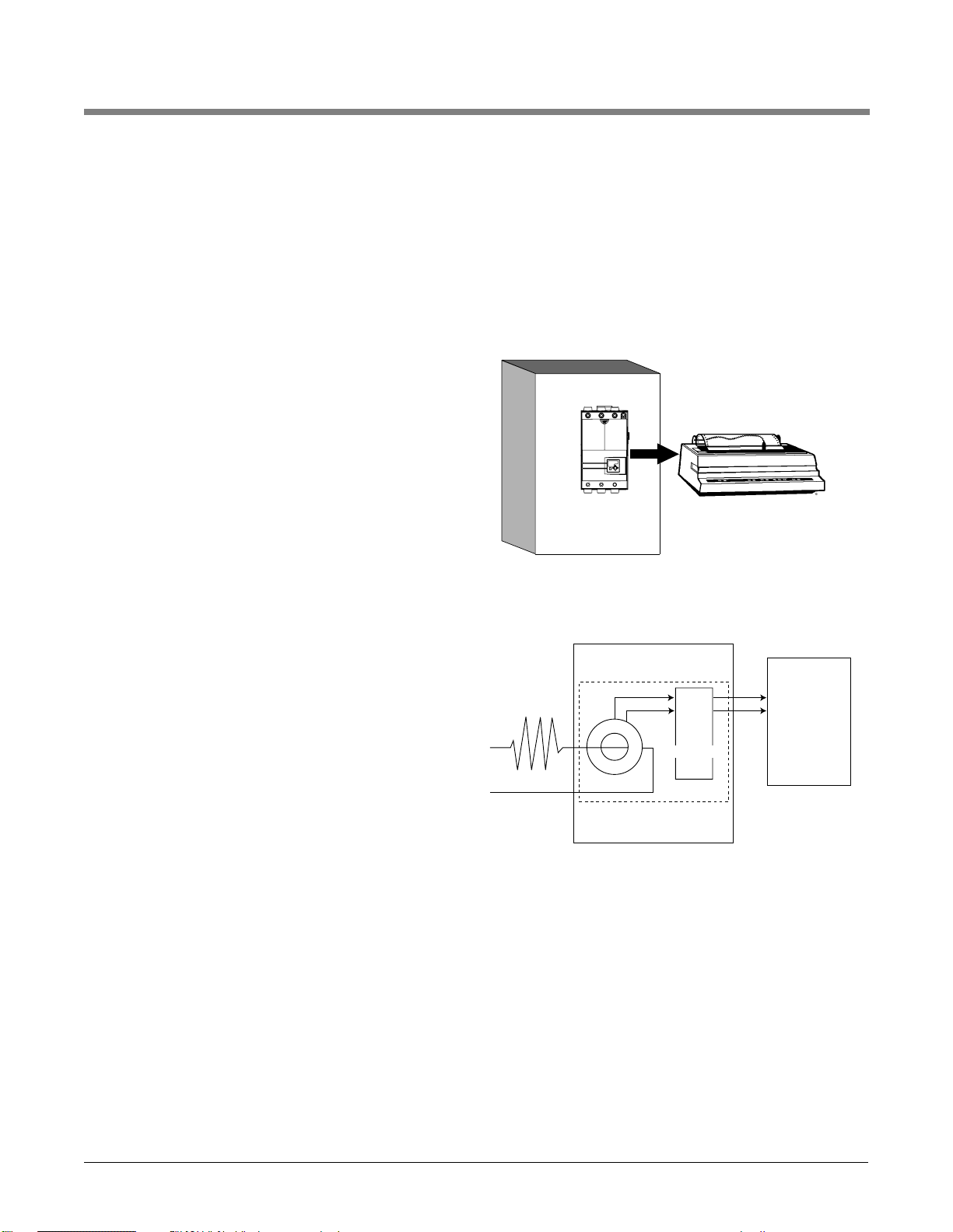
Retransmitting Output Load Current or
Load Power
The retransmit feature allows an output to
retransmit an analog signal that can serve as an
input variable for another device such as a chart
recorder to document system performance over time.
To use the retransmit feature a Power Series must
be equipped with heater diagnostics and a universal
retransmit board (P_ _ 1 - _ _ _ _ - _ 1 _ _).
Setup Page:
• Enter the Setup Page by holding ± ¬for 2 seconds.
• When the display reads [algo], press Î until[retr]
[`set] [`set]
is displayed. Press ® :
Select [`Cfg] to choose the type of output
retransmitted, mA [`nna] or volts [UOlt].
Select [type] to choose the type of information
that will be retransmitted.
[nOne] retransmit not active.
[`CUr] retransmits the load current of
selected phase [phas] or zone [2one] if it is a
multizone unit.
[`HUa] retransmits the load power of selected
zone [2one] in all models.
Select phase [phas] or zone [2one] to choose the
phase/zone that will represent your retransmit
signal. A three phase unit can only be single zone.
To scale the retransmit output signal, set the low
value load current or kVA to be retransmitted with
[Cur_] or [HUa_] and set the high value load current or kVA to be retransmitted with [Cur–] or
[HUa–]. For example, if you want 4-20mA to represent
a 50A to 250A current, set [Cur_] to 50 and [Cur–]
to 250. As the load current varies between 50 and
250A, the retransmit output will vary between 4mA
and 20mA.
Current outputs are hardware limited to 0 to 20mA,
but may be scaled using the {rt| C_] and {rt| C–]
prompts.
Voltage outputs are hardware limited to 0 to 10V,
but may be scaled using the {rt| U_] and {rt| U–]
prompts.
Figure 5.9a — Retransmitting a remote set point.
Figure 5.9b — Example circuit.
Power Series
Heater
CT
Power Series
Retransmit
Circuit
Recorder
Device
Page 32

Fast Start Guide
Get Your Power Series Controlling Heat
Single Phase Control
Apply power to the line and the electronics power
supply. The displays will read [`___]
[load]
• Enter the Setup Page holding ± ¬ for 2 seconds.
• When the display reads [algo] ® to [`Off],
[`set] [algo]
then cycle thru the list of choices using the ÓÎ
keys. Choose one*.
[cont] dc contactor
[`Off] non-operational
[`Ftb] fixed time base, zero cross
[Urtb] variable time base, zero cross
[PH2t] phase angle
Press ¬.
• At [algo], press Î to [Ctr1].
[`set] [`set]
• **Press ® until [`nna] (default) is displayed.
[``In]
Using the Ó Î keys, select input type: [`Off]
off, [`nna] current, [Uolt] voltage, or [`dig]
keyboard or comms.
• **Press ® until [nna_] or [Uol_] is displayed.
[Ctr1] [Ctr1]
Using the Ó Î keys, set the low end of the input
scale to the desired input.
• **Press ® until [nna–] or [Uol–] is displayed.
[Ctr1] [Ctr1]
Using the Ó Î keys, set the high end of the
input scale to the desired input.
• **Press ® until [IDLE] is displayed.
[lrn;U]
Using the Ó Î keys, select [`req] , and the Power
Series will set the baseline voltage. Line voltage compensation, under voltage alarm, and some internal operating parameters are based on this.
*NOTE: One type of power control algorithm must be
selected for all zones.
**NOTE: Repeat this procedure for each zone in multizone
configurations.
Three Phase Control
Apply power to the line and the electronics power
supply. The displays will read [`___]
[load]
• Enter the Setup Page holding ± ¬ for 2 seconds.
• When the display reads [````] ® to [````],
[`set] [algo]
then cycle thru the list of choices using the Ó
key. Choose one.
[cont] dc contactor
[`Off] non-operational
[`Ftb] fixed time base, zero cross
[Urtb] variable time base, zero cross
[PH2t] phase angle
Press ¬.
• At [algo], press Î to [Ctr1].
[`set] [`set]
• **Press ® until [````] (default) is displayed.
[``In]
Using the Ó key, select input type: [`Off] off,
[`nna] current, [Uolt] voltage, or [`dig] keyboard
or comms.
• Press ® until [nna_] or [Uol_] is displayed.
[Ctr1] [Ctr1]
Using the Ó or Î key, set the low end of the input
scale to the desired input.
• Press ® until [nna–] or [Uol–] is displayed.
[Ctr1] [Ctr1]
Using the Ó or Î key, set the high end of the input
scale to the desired input.
• Press ® until [IDLE] is displayed.
[lrn;U]
Using the Ó Î keys, select [`req] , and the Power
Series will set the baseline voltage. Line voltage compensation, under voltage alarm, and some internal operating parameters are based on this.
• Press ® until [````] is displayed.
[type]
Select the load type for Zone 1. (Choice is dependent on unit hardware.)
[2l`d] 3 ph, 2-leg delta
[2lod] 3 ph, 2-leg open delta
[2luy] 3 ph, 2-leg ungrounded wye
[none] unconfigured
[3lid] 3 ph, 3-leg, 6 SCR inside delta
[3l`d] 3 ph, 3-leg, 6 SCR delta
[3lgy] 3 ph, 3-leg, 6 SCR grounded wye
• Press ± to start the Power Series.
5 . 1 0 I F e a tu r e s W a t lo w P owe r Se r i es
Page 33
Display Loop
The resting-state display shows one of the following sets of data, depending on controller
setup. The first prompt appears in the top display, the second in the bottom display.
Active: Always.
Appears in Display Loop.
150 r [mA]
151 r [V]
5102 r/w
[dig]
[``)0][``)0] to [2)00] [mA]
(0 to 2000)
[``)0] to [1)00] [V]
(0 to 1000)
[``)0] to [10)0] [%]
(0 to 1000)
0.1 increments
[``In] Analog (mA or V)
or Numeric (%)
Input Signal
Displays mA/V analog input; selects
numeric % power.
Single Zone / Single Phase
Active: Always.
Appears in Display Loop.
198 rn/a
[``47] to [``63]
[47 to 63]
[frEq] Line Frequency
(Hz)
Displays the AC line.
Active: Always.
Appears in display loop.
(In single phase, single zone, only
the center LED operates; in single
phase, 2-zone, or 3-phase, 2-leg,
only the outside LEDs operate; in
3-phase, 3-leg, and multizone,
each zone operates a separate
LED.)
[`___][``-`] or [``_`]
per display
v
[LoAd] Load Activity
Indicator
Displays [``-`] if
load has power
applied.
Active: Any active error.
See Appendix, pp. A.4-7.
195 r n/a
[````] Inactive (0)
[`err] Active (1)
(See Appendix A.7 for
values)
[```] Display Loop
Errors
[alpha) (if any)
Displays present
error conditions.
Active: Any active unmasked
alarm.
Individual Modbus registers may
have [Unla] Unlatched (4)
written to them to clear a
latched alarm.
NOTE: a latched alarm must be
[[``llaatt]]
Latched Inactive (3) before it can be
unlatched.
181 to 190
r/w
[[`alr] Active (1)
[`lat] Latched Active
(2)
[`lat] Latched Inac-
tive (3)
[Unla] Unlatched (4)
[```] Active Alarms
[alpha) (if any)
Displays present
alarm conditions.
System Information
Display Parameter Range Default Modbus Conditions for
(Modbus Value) Register Parameters to Appear
read/write
Parameters, Chapter 6 Watlow Power Series ■ 6.1
Chapter Six
Parameters
6
Page 34
Active if heater diagnostics option
is installed and heater bakeout
is running in the zone.
157 r [1]
167 r [2]
n/a
[9999] to [```0]
[minutes]
(9999 to 0)
[Hbt1], [Hbt2] Heater
Bakeout Timeout
Displays the time
left on a heater
bakeout.
Active with multizone
configuration.
159 r [1]
169 r [2]
[``)0][``)0] to [10)0]
(0 to 1000)
[Out1], [Out2]
Output Power (%)
Displays present output power.
Active with multizone
configuration.
mA, r [1][2]
150,160
V, r [1][2]
151,161
dig, r/w [1][2]
5102, 5202
[``)0][``)0] to [1)00] [V]
(0 to 1000)
[``)0] to [2)00] [mA]
(0 to 2000)
[``)0] to [10)0] [%]
(0 to 1000)
0.1 increments
[In`1], [In`2]
Analog (mA or V)
or Numeric (%)
Input Signal
Displays mA/V
analog input; selects
numeric % power.
Active with multizone
configuration.
n/a1
[```1] to [```2][```1], [```2]
[2one] Display Zone
Selection
Select Zone 1 or 2 for
display.
Two Zone, Single Phase
Active if heater diagnostics option
is installed.
156 r n/a
[```0] to [9999]
(0 to 9999)
[`HUa] Load Power
(kVA)
Displays (est.) calculated load power.
Active if heater diagnostics option
is installed.
164 rn/a
[```0] to [9999]
(0 to 9999)
[`Cur] Load Current
(Amps) rms
Displays measured
load current.Peak
current converted to
rms, then multiplied
by % power = average rms current
measured by the onboard CT.
Active: Always.
Appears in Display Loop.
162 rn/a
[```0] to [9999]
(0 to 9999)
[`UoL] Line Potential
(Volts) rms
Displays measured
line voltage.
Active if heater diagnostics option
is installed and heater bakeout
is running in the zone.
157 r [1]n/a
[9999] to [```0]
[minutes]
(9999 to 0)
[`Hbt] Heater Bakeout
Timeout
Displays the time
left on a heater
bakeout.
Active: Always.
Appears in Display Loop.
159 r
[``)0][``)0] to [10)0]
(0 to 1000)
[`Out] Output Power (%)
Displays present output power.
6.2 ■ Watlow Power Series Parameters, Chapter 6
Display Parameter Range Default Modbus Conditions for
(Modbus Value) Address Parameters to Appear
read/write
Page 35
Active with multizone
configuration.
152 r [1]
162 r [2]
172 r [3]
n/a
[```0] to [9999] [V]
(0 to 9999)
[Uol1], [Uol2], [Uol3]
Line Potential
(Volts) rms
Read measured line
voltage.
Active if heater diagnostics option
is installed and heater bakeout
is running in the zone.
157 r [1]
167 r [2]
177 r [3]
n/a
[9999] to [```0]
[minutes]
(9999 to 0)
[Hbt1], [Hbt2], [Hbt3]
Heater Bakeout
Timeout
Displays the time
left on a heater
bakeout cycle.
Active with multizone
configuration.
159 r [1]
169 r [2]
179 r [3]
[``)0][``)0] to [10)0] [%]
(0 to 1000)
[Out1], [Out2], [Out3]
Output Power (%)
Displays present output power.
Active with multizone
configuration.
mA, r[1][2][3]
150,160,170
V, r[1][2][3]
151,161,171
dig, r/w
[1][2][3]
5102, 5202,
5302
[``)0][``)0] to [2)00] [mA]
(0 to 2000)
[``)0] to [1)00] [V]
(0 to 1000)
[``)0] to [10)0] [%]
(0 to 1000)
0.1 increments
[In`1], [In`2], [In`3]
Analog (mA or V)
or Numeric (%)
Input Signal
Displays mA/V
analog input; selects
numeric % power.
Active with multizone
configuration.
n/a1
[```1] to [```3][```1], [```2] [```3]
[2one] Display Zone
Selection
Select Zone 1, 2 or 3
for display.
Three Zone, Single Phase
Active with multizone
configuration and heater diagnostics option is installed.
156 r [1]
166 r [2]
n/a
[```0] to [9999]
(0 to 9999)
[HUa1], [HUa2]
Load Power (kVA)
Read calculated
(est.) load power.
Active with multizone
configuration and heater diagnostics option is installed.
154 r [1]
174 r [2]
n/a
[``00] to [9999]
(0 to 9999)
[Cur1], [Cur2]
Load Current
(Amps) rms
Read measured line
current.
Active with multizone
configuration.
152 r [1]
172 r [2]
n/a
[```0] to [9999]
(0 to 9999)
[Uol1], [Uol2]
Line Potential
(Volts) rms
Read measured line
voltage.
Display Parameter Range Default Modbus Conditions for
(Modbus Value) Address Parameters to Appear
read/write
Parameters, Chapter 6 Watlow Power Series ■ 6.3
NOTE: For more information about how parameter settings affect the controller’s operation, see Chapter Five, Control
Methods and Features.
NOTES:
What you see in each Page and in each Menu are factory set, depending on the options and settings in your controller.
Current operating parameters may be modified at any time with the use of a keypad or serial input.
The Input Signal Method Indicator will change depending on the Input Signal Method chosen — process, current, or volts.
Page 36
6.4 ■ Watlow Power Series Parameters, Chapter 6
Active with multiphase
configuration and heater diagnostics option is installed.
156 r n/a
[```0] to [9999]
[kVA]
(0 to 9999)
[`HUA] Load Power (kVA)
Read calculated
(est.) load power.
NOTE: In 3 phase, 2-leg systems,[Cur2] is the current displayed; it is the average of phase 1 and phase 3 ( [Cur1] and
[Cur3] ).
Active with multiphase
configuration and heater diagnostics option is installed.
154 r [1]
164 r [2]
174 r [3]
n/a
[``00] to [9999] [A]
(0 to 9999)
[Cur1], [Cur2], [Cur3]
Load Current
(Amps) rms
Read measured load
current.
Active with multiphase
configuration.
152 r [1]
162 r [2]
172 r [3]
n/a
[``00] to [9999] [V]
(0 to 9999)
[Uol1], [Uol2], [Uol3]
Line Potential
(Volts) rms
Read measured line
voltage.
Active with multiphase
configuration.
n/a
[```1] to [```3][```1], [```2], [```3]
[Phas] Display Phase
Selection 1 to 3
Select phase for
display.
Active: Always.
Appears in Display Loop.
159 r
[``)0][``)0] to [10)0] [%]
(0 to 1000)
[`Out] Output Power (%)
Displays present output power.
Active: Always.
Appears in Display Loop.
151 r [V]
150 r [mA]
5102 r/w
[dig]
[``)0][``)0] to [2)00] [mA]
(0 to 2000)
[``)0] to [1)00] [V]
(0 to 1000)
[``)0] to [10)0] [%]
(0 to 1000)
0.1 increments
[``In] Analog (mA or V)
or Numeric (%)
Input Signal
Displays mA/V
analog input; selects
numeric % power.
Multi-Phase
Active with multizone
configuration and heater diagnostics option is installed.
156 r [1]
166 r [2]
176 r [3]
n/a
[```0] to [9999]
[kVA]
(0 to 9999)
[HUa1], [HUa2], [HUa3]
Load Power (kVA)
Read calculated
(est.) load power.
Active with multizone
configuration and heater diagnostics option is installed.
154 r [1]
164 r [2]
174 r [3]
n/a
[``00] to [9999] [A]
(0 to 9999)
[Cur1], [Cur2], [Cur3]
Load Current
(Amps) rms
Read measured line
current.
Display Parameter Range Default Modbus Conditions for
(Modbus Value) Address Parameters to Appear
read/write
Page 37

Setup Page
To enter the Setup Page, press the Home and Left keys (± ¬ ) together while in the Display Loop.
Each of the following menus in the Factory Page are selected by pressing the
Increment/Decrement keys (Ó Î ). Each press of the button will scroll you up or down
through these main menu options.
To select a parameter within a menu, use the Left/Right arrow keys (¬ ® ). The parameter
appears in the bottom display.
To select a value for each parameter (either alpha or numeric), use the Increment/Decrement
keys (Ó Î ). The value appears in the upper display.
Pressing the Home key (± ) in this menu will return you to the Display Loop.
The Setup Page contains ten menus:
Active if [algo] is set to [`ftb].
56 r/w
[1SEC] 1
second (0)
[1SEC] 1 second (0)
[4SEC] 4 second (1)
[`FTB] Fixed Time Base
(Sec)
Set the fixed time
base in seconds for
selected zone.
Active: Always.
[cont] is not available if any
input on controller is digital.
[PH2t] phase angle is not
available with 3 phase, 2-leg
controllers.
NOTE: Changing this parameter will
restart the system.
55 r/w
[`Off] non-
operational
(1)
[cont] dc contactor (0)
[`Off] non-operational
(1)
[`Ftb] fixed time base,
zero cross (2)
[Urtb] variable time
base, zero cross (3)
[PH2t] phase angle (4)
[ALgo] Power Control
Algorithm Select
Select power control
algorithm.
[algo] Setup Control Algorithm
[`Set] Setup Page
This menu is used to set the control algorithm for the system.
NOTE: Changing the algorithm will restart the system.
*NOTE: These menus are dependent on
the hardware options that are installed
in your controller. Please see the individual menus for the options that must
be installed for each of these menus to
appear.
[algo][algo] Control
Algorithm
[Ctr1] Control Zone 1
[Opt1] *Options Zone 1
[Ctr2] Control Zone 2
[Opt2] *Options Zone 2
[Ctr3] Control Zone 3
[Opt3] *Options Zone 3
[`ALr] Alarms
Configuration
[COM] *Comms
Configurations
[rEtr] *Retransmit
Configuration
[`Set] Setup Page Select
Go to a setup menu.
Display Parameter Range Default Modbus Conditions for
(Modbus Value) Register Parameters to Appear
read/write
Parameters, Chapter 6 Watlow Power Series ■ 6.5
NOTE: For more information about how parameter settings affect the controller’s operation, see Chapter Five, Control
Methods and Features.
Page 38
Display Parameter Range Default Modbus Conditions for
(Modbus Value) Address Parameters to Appear
read/write
6.6 ■ Watlow Power Series Parameters, Chapter 6
Active if [``In] is set to [Uolt]
voltage.
5013 r/w [1]
5023 r/w [2]
5033 r/w [3]
[`)00] (0)[`)00] to
[Uol–] [- 2.5V]
(0 to Analog Input
High Voltage [-2.5V])
[Uol_] Analog Input Low
Voltage (Volts)
Sets voltage value
which will correspond to 0% power if
input is voltage type.
Active if [``In] is set to [`nna]
current.
5012 r/w [1]
5022 r/w [2]
5032 r/w [3]
[2)00]
(2000)
[nna_] [+ 5mA] to
[9(99]
(Analog Input Low
Current [+5mA] to
9999)
[nna–] Analog Input High
Current (mA)
Sets current value
which will correspond to 100%
power if input is
current type.
Active if [``In] is set to [`nna]
current.
5011 r/w [1]
5021 r/w [2]
5031 r/w [3]
[`)00] (0)[`)00] to [nna–]
[- 5mA]
(0 to Analog Input
High Current[-5mA])
[nna_] Analog Input Low
Current (mA)
Sets current value
which will correspond to 0% power if
input is current type.
Active if input signal method is
set to [`dIG].
5103 r/w [1]
5203 r/w [2]
5303 r/w [3]
[``)0] (0)[``)0] 0 percent to
[10)0] 100 percent
(0 to 1000)
[dFlt] Default Numeric
Input Signal (%)
Selects the power-on
level for chosen zone.
Active: Always.
[`dig] is not available if [Set`]
® [algo] in the Setup Page is
set to [cont].
5101 r/w [1]
5201 r/w [2]
5301 r/w [3]
[`nna] cur-
rent (1)
[`OFF] off (0)
[`nna] current (1)
[Uolt] voltage (2)
[`dig] keyboard or
comms (3)
[``In] Input Signal
Method Select
(dig, mA, Volt)
Select the input
signal method for
chosen zone.
[Ctr1] [Ctr2] [Ctr3] Setup Control Zone 1, 2, and 3 Menus
[`Set] [`Set] [`Set] Setup Page
This menu is used to set up the control for the chosen zone.
Zone 1 is used if Input/Output Configuration is single phase, single zone, or three phase.
Zone 1 and 2 are used if Input/Output Configuration is single phase, two zones.
All zones are used if Input/Output Configuration is single phase, three zones.
Active: Always.80 r/w
[``ON]] on
(0)
[``ON] on (0)
[`Off] off (1)
[``UC] Line Voltage Com-
pensation
Automatically adjusts
output duty cycle to
compensate for line
voltage fluctuations.
Page 39

Display Parameter Range Default Modbus Conditions for
(Modbus Value) Register Parameters to Appear
read/write
Parameters, Chapter 6 Watlow Power Series ■ 6.7
NOTE: For more information about how parameter settings affect the controller’s operation, see Chapter Five, Control
Methods and Features.
Active if controller is a 3 phase
system which only has one
zone.
NOTE: The parameters available are
dependent on the controller’s
input/output configuration. The system
does not operate unless this prompt is
set to something other than
[[nnoonnee]]
.
NOTE: Changing this parameter will
restart the system.
58 r/w
[none] un-
configured
(3)
[2l`d] 3 ph, 2-leg
delta (0)
[2lod] 3 ph, 2-leg open
delta (1)
[2luy] 3 ph, 2-leg un-
grounded wye (2)
[none] unconfigured (3)
[3lid] 3 ph, 3-leg, 6
SCR inside delta (4)
[3l`d] 3 ph, 3-leg, 6
SCR delta or ungrounded wye (5)
[3lgy] 3 ph, 3-leg, 6
SCR grounded wye
(7)
[type] Load Type Select
(Control Zone 1
only, 3 phase only.)
Select the load type
for Zone 1.
Active: Always.
Go to [lrn| U], set the controller to
[`req]. Wait 5 sec. for automatic input of data for controller. The display will go back
to [idle] when done.
5591 r/w [1]
5592 r/w [2]
5593 r/w [3]
[idle] idle
(0)
[`err] invalid input
signal (-1)
[idle] idle (0)
[`req] learn request
(1)
[lrn| U] Baseline Voltage
Learn Request
Allows software to
learn the baseline
voltage on line
connected to the
zone chosen.
Active: Always.5594 r/w [1]
5595 r/w [2]
5596 r/w [3]
Line Voltage
rating
Minimum to maximum
line voltage
(minimum to maximum
line voltage)
[bl`U] Baseline Voltage
Read/Adjust
Shows the value for
baseline voltage and
allows manual adjustment of this value.
Active if [``In] is set to [`nna]
current or [Uolt] voltage.
Go to [lrn| a], set analog input to
low limit and set the controller
to [``lO] low limit. Wait 5 sec.
for automatic input of low data
for controller. The display will
go back to [idle] when done.
Go to [lrn| a], set the analog
input to high limit and set the
controller to [``HI] high limit.
Wait 5 sec. for automatic input
of high data for controller. The
display will go back to [idle]
when done.
5019 r/w [1]
5029 r/w [2]
5039 r/w [3]
[idle] idle
(0)
[`err] invalid input
signal (-1)
[idle] idle (0)
[``lO] low limit learn
request (1)
[``HI] high limit learn
request (2)
[lrn| a] Learn Input Learn
Request (Hi, Lo)
Allows software to
learn the high and
low limits of the
analog input signal.
Active if [``In] is set to [Uolt]
voltage.
5014 r/w [1]
5024 r/w [2]
5034 r/w [3]
[1)00]
(1000)
[Uol_] [+ 2.5V] to
[9(99]
(Analog Input Low
Voltage [+2.5V] to
9999)
[Uol–] Analog Input High
Voltage (Volts)
Sets voltage value
which will correspond to 100%
power if input is
voltage type.
Page 40
Active if heater diagnostics is
installed.
Active unless controller is 3
phase, 2 leg configuration.
Active if [`Hbo] is set to [``On].
5116 r/w [1]
5216 r/w [2]
5316 r/w [3]
10.0% of load
current
[```0] to [`Cur] 0 to
Load Current Amps
[1 Amp increment;
maximum will be determined by Load
Rating] (0 to Load
Current Amps)
[`HbC] Heater Bakeout
Over Current Trip
Sets the maximum
heater current during heater bakeout.
Output will shut
down at this value.
Active if heater diagnostics is
installed.
Active unless controller is 3
phase, 2 leg configuration.
Active if [`Hbo] is set to [``On].
5111 r/w [1]
5211 r/w [2]
5311 r/w [3]
1440 minutes
(1440)
[```0] to [9999] 0 to
9999 minutes [1
minute increments]
(0 to 9999)
[Min] Heater Bakeout
Select Time
Selects the heater
bakeout time in minutes for chosen zone.
Active if heater diagnostics is
installed.
Active unless controller is 3
phase, 2 leg configuration.
5110 r/w [1]
5210 r/w [2]
5310 r/w [3]
[`OFF] off (0)[`OFF] off (0)
[``On] selected (1)
[`Hbo] Heater Bakeout
Select (On/Off)
Select heater bakeout option for chosen
zone.
[OPt1] OPt2] [OPt3] Setup Options Zones 1, 2, and 3 Menus
[`Set] [`Set] [`Set] Setup Page
This menu is used to set up the options for the chosen zone. This set of menus is available only if
Heater Diagnostics is installed.
Zone 1 is used if Input/Output Configuration is single phase, single zone, or three phase.
Zone 1 and Zone 2 are used if Input/Output configuration is single phase, two zones.
All zones are used if Input/Output Configuration is single phase, three zones.
Active if [algo] is set to [Ph2t]
and [type] is set to [3ld] or
[3lid].
5108 r/w
[``)0] (0) [``)0] to [`5)0]
(0 to 500)
[rdLy] Reactance Delay
for Transformer
Loads
Prevents half cycle
errors and restarts
on inductive loads.
Increase value until
half cycle errors no
longer appear.
Active unless Input/Output con-
figuration is 3 phase, 2-leg.
Active if [algo] is set to [Ph2t].
5105 r/w [1]
5205 r/w [2]
5305 r/w [3]
[``$0] (40) [``)0] to [12)0] 0.0
to 120 seconds (.1
second increments)
(0 to 1200)
[Soft] Soft Start Time
(Sec)
Selects the time in
seconds for the
power level of the
chosen zone to
change from 0% to
100% when the
power cycles.
Active unless Input/Output con-
figuration is 3 phase, 2-leg.
Active if [algo] is set to [Ph2t].
5104 r/w [1]
5204 r/w [2]
5304 r/w [3]
[`1)0] (100) [``)1] to [10)0] 0.0
to 100.0% [.1% increments]
(1 to 1000)
[rATE] Maximum Rate of
Change
(%/100msec)
Set maximum rate of
power change of the
power level for
selected zone when
input signal changes.
Display Parameter Range Default Modbus Conditions for
(Modbus Value) Address Parameters to Appear
read/write
6.8 ■ Watlow Power Series Parameters, Chapter 6
Page 41

Active if heater diagnostics is
installed.
Active unless Input/Output con-
figuration is 3 phase, 2-leg.
Active if [algo] is set to [ph2t]
and [Indf] is set to [`req].
5107 r/w [1]
5207 r/w [2]
5307 r/w [3]
Active load
current
0 to load current rating
[ICur] Inductive Current
Sets the actual measured current for an
inductive load.
Active if heater diagnostics is
installed.
Active unless Input/Output con-
figuration is 3 phase, 2-leg.
Active if [algo] is set to [ph2t].
NOTE: Selecting [`act] or [`CLr]
will restart the system.
5106 r/w [1]
5206 r/w [2]
5306 r/w [3]
[Idle] idle
(0)
[`err] invalid request
(-1)
[Idle] idle (0)
[`req] request induc-
tive load factor adjustment (1)
[`act] active load fac-
tor adjustment (2)
[`CLr] clears factor (3)
[Indf] Inductive Load
Factor Request
Requests an inductive load factor adjustment.
Active if heater diagnostics is
installed.
This set point will only be used if
the requested power is above
20%.
5115 r/w [1]
5215 r/w [2]
5315 r/w [3]
maximum
system current
[tol_] to maximum
system current [1
amp increments]
(Heater Low Tolerance Set Point to
max Load Current
rating of the Power
Series)
[tol–] High Tolerance
Set Point (A)
Set heater tolerance
high current set point
for the selected zone.
Value is current level
for 100% full on.
Active if heater diagnostics is
installed.
This set point will only be used if
the requested power is above
20%.
5114 r/w [1]
5214 r/w [2]
5314 r/w [3]
0 (0)
[```0] to [tol–] 0
amps to High Tolerance Set Point [1
amp increments]
(0 to Heater High
Tolerance Set Point)
[tol_] Low Tolerance Set
Point (A)
Set heater tolerance
low current set point
for the selected zone.
Value is current level
for 100% requested
power and is adjusted actual percentage
of requested power.
Active if heater diagnostics is
installed.
Active unless controller is 3
phase, 2 leg configuration.
Active if [algo] is set to [Ph2t]
and [`CLi] is set to [``On].
NOTE: Changing this parameter will
restart the system.
5113 r/w [1]
5213 r/w [2]
5313 r/w [3]
10.0% of load
current
[```0] to [`Cur] 0 to
Load Current Amps
[1 Amp increment;
maximum will be determined by Load
Rating] (0 to Load
Current Amps)
[CL`A] Current Limit Set
Point (A)
Selects the current
limit set point for
current limiting in
chosen zone.
Active if heater diagnostics is
installed.
Active unless controller is 3
phase, 2 leg configuration.
Active if [algo] is set to [Ph2t].
NOTE: Changing this parameter will
restart the system.
5112 r/w [1]
5212 r/w [2]
5312 r/w [3]
[`OFF] off (0)[`OFF] off (0)
[``On] on (1)
[`CLi] Current Limit Se-
lect (On/Off)
Selects current limit
method for selected
zone. Used in phase
angle control only.
Display Parameter Range Default Modbus Conditions for
(Modbus Value) Address Parameters to Appear
read/write
Parameters, Chapter 6 Watlow Power Series ■ 6.9
NOTE: For more information about how parameter settings affect the controller’s operation, see Chapter Five, Control
Methods and Features.
Page 42

Active if [glbl] is set to [`Off].
863 r/w
[`std]
active (0)
[`std] active (0)
[`LaT] latched (1)
[`SIl] silenced (2)
[LaSI] latched and
silenced (3)
[Line] Line Loss Alarm
Configuration
Selects the line loss
alarm configuration.
Active: Always.
Output will de-energize at this
heatsink shut down temperature (degrees C). The default
maximum temperature is
model number dependent.
990 r/w Value equal to
[`sdÇ] or
less. User
adjustable.
See Factory
Menu for
actual safety
shutdown
temp.
[```0] to [`sdÇ] [alÇ`] Heat Sink Over
Temperature Alarm
Temperature
Select heat sink
overtemp alarm
configuration.
Active if [glbl] is set to [`Off].
862 r/w
[`std]
active (0)
[`std] active (0)
[`LaT] latched (1)
[`SIl] silenced (2)
[LaSI] latched and
silenced (3)
[``OT] Heat Sink Over
Temperature
Alarm Config.
Select over temperature alarm configuration.
Active if heater diagnostics is
installed.
Active if [glbl] is set to [`Off].
861 r/w
[`std]
active (0)
[`std] active (0)
[`LaT] latched (1)
[`SIl] silenced (2)
[LaSI] latched and
silenced (3)
[`tol] Heater Tolerance
Alarm Config.
Selects heater
tolerance alarm
configuration.
Active if heater diagnostics is
installed.
Active if [glbl] is set to [`Off].
860 r/w
[`std]
active (0)
[`std] active (0)
[`LaT] latched (1)
[`SIl] silenced (2)
[LaSI] latched and
silenced (3)
[Open] Heater Open
Alarm Config.
Select heater open
alarm configuration.
Active: Always.851 r/w
[`std] all
alarms
active (0)
[`std] all alarms
active (0)
[`LaT] latched (1)
[`SIl] silenced (2)
[LaSI] latched and
silenced (3)
[`Off] off (4)
[glbl] Global Alarm
Configuration
Selects global alarm
configuration. Configures all alarms to the
same type or if set to
OFF allows individual
alarm configuration.
Active: Always.
850 r/w
[al`O] de-
energized
on alarm
(1)
[al`C] energized on
alarm (0)
[al`O] de-energized
on alarm (1)
[a| lgc] Active Relay State
Select the relay
state on an alarm
condition.
[`Alr] Setup Alarms Configuration Menu
[`Set] Setup Page
This menu is used to set up the alarm configuration. For a definition of the alarm types —
standard, latched, silenced, latched and silenced, see page 5.7.
6.10 ■ Watlow Power Series Parameters, Chapter 6
Display Parameter Range Default Modbus Conditions for
(Modbus Value) Address Parameters to Appear
read/write
Page 43

Active if communications is
installed.
Active if [glbl] is set to [`Off].
869 r/w
[`std]
active (0)
[`std] active (0)
[`LaT] latched (1)
[`SIl] silenced (2)
[LaSI] latched and
silenced (3)
[C| wd] Comms Watchdog
Alarm Config.
Selects the communications watchdog
alarm configuration.
Active if [glbl] is set to [`Off].
868 r/w
[`std]
active (0)
[`std] active (0)
[`LaT] latched (1)
[`SIl] silenced (2)
[LaSI] latched and
silenced (3)
[``OU] Over Voltage
Alarm Config.
Selects the line overvoltage alarm configuration.
Active if [glbl] is set to [`Off].
867 r/w
[`std]
active (0)
[`std] active (0)
[`LaT] latched (1)
[`SIl] silenced (2)
[LaSI] latched and
silenced (3)
[``UC] Voltage Compensa-
tion Alarm Config.
Selects the line compensation alarm configuration.
Active if [glbl] is set to [`Off].
866 r/w
[`std]
active (0)
[`std] active (0)
[`LaT] latched (1)
[`SIl] silenced (2)
[LaSI] latched and
silenced (3)
[Freq] Frequency Out of
Tolerance Alarm
Configuration
Select frequency tolerance alarm configuration.
Active if heater diagnostics is
installed.
Active if controller is 3 phase.
991 r/w
[`100] (100)[```0] to [`100]
(0 to 100)
[Ldif] Load Balance
Percentage
Selects the minimum percentage
difference between
loads current in
phases.
Active if heater diagnostics is
installed.
Active if [glbl] is set to [`Off].
Active if controller is 3 phase.
865 r/w
[`std]
active (0)
[`std] active (0)
[`LaT] latched (1)
[`SIl] silenced (2)
[LaSI] latched and
silenced (3)
[Lbal] Load Balance
Alarm Config.
Selects the load
balance alarm
configuration.
Active if controller is 3 phase, 3-
leg configuration.
Active if [glbl] is set to [`Off].
864 r/w
[`std]
active (0)
[`std] active (0)
[`LaT] latched (1)
[`SIl] silenced (2)
[LaSI] latched and
silenced (3)
[p| bAl] Phase Balance
Alarm Config.
Select phase balance
configuration.
Parameters, Chapter 6 Watlow Power Series ■ 6.11
NOTE: For more information about how parameter settings affect the controller’s operation, see Chapter Five, Control
Methods and Features.
Display Parameter Range Default Modbus Conditions for
(Modbus Value) Address Parameters to Appear
read/write
Page 44
Active if retransmit and heater
diagnostics options are installed.
871 r/w
[`CUr] cur-
rent (1)
[`Off] none (0)
[`CUr] current (1)
[`HUA] kVA (2)
[type] Retransmit Type
Select
Select type of
retransmit information; amps or kVA.
Active if retransmit and heater
diagnostics options are installed.
870 r/w
{`nna] mA
(0)
{`nna] mA (0)
{UOlt] volts (1)
[`Cf9] Retransmit
Config. Select
Select type of
retransmit output.
[rEtr] Setup Retransmit Configuration Menu
[`Set] Setup Page
This menu is used to set up the retransmit parameters. The menu is not available unless
Retransmit and Heater Diagnostics are installed.
Active if serial communications
option is installed and [`Wd]
Watchdog is set to {``On].
87 r/w
[``)0] 0 per-
cent (0)
[``)0] 0 percent to
[10)0] 100 percent
(0 to 1000)
[PWr] Watchdog Failure
Output Power
Select
Selects the default
power level for a
watchdog timeout.
Active if serial communications
option is installed and [`Wd]
Watchdog is set to {``On].
86 r/w
[9999]
(9999)
[```0] to [9999] (0
to 9999)
[`seC] Watchdog Timeout
(Sec)
Selects a timeout in
seconds for the
communications
watchdog.
Active if serial communications
option is installed.
85 r/w
{`Off] off (0){`Off] off (0)
{``On] on (1)
[`Wd] Watchdog Select
(On/Off)
Turns on a watchdog
for communications.
Active if serial communications
option is installed.
[9600] 9600
baud
[1200] 1200 baud
[2400] 2400 baud
[4800] 4800 baud
[9600] 9600 baud
[1(2`] 19.2K baud
[baud] Unit Baud Rate
Select
Select baud rate for
communications.
Active if serial communications
option is installed.
[```1] [```1] to [`247] [Addr] Unit Address Select
Select device
address for
communications.
[COm] Setup Comms Configuration Menu
[`Set] Setup Page
This menu is used to set up the communications parameters. This menu is not available unless
Serial Communications is installed.
6.12 ■ Watlow Power Series Parameters, Chapter 6
Display Parameter Range Default Modbus Conditions for
(Modbus Value) Register Parameters to Appear
read/write
Page 45

Active if retransmit and heater
diagnostics options are installed.
Active if [`Cfg] is set to [`nna].
883 r/w
[2)00]
(2000)
[rt|C_] to [2)00]
(Retransmit Output
Low Current to 2000)
[rt| C–] Retransmit Out-
put High Current
(mA)
Select output
current that will
correspond to
[Cur–] or [HUA–].
Active if retransmit and heater
diagnostics options are installed.
Active if [`Cfg] is set to [`nna].
882 r/w
[```0] (0)[`)00] to [rt|C–]
(0 to Retransmit Output High Current)
[rt| C_] Retransmit Out-
put Low Current
(mA)
Select output
current that will
correspond to
[Cur_] or [HUA_].
Active if retransmit and heater
diagnostics options are installed.
Active if [retr] ® [type] is set
to [`HUa].
879 r/w
[9999]
(9999)
[HUA_] to [9999]
(Minimum kVA Retransmit to 9999)
HUA–] Maximum kVA
Retransmit
Select maximum
load power to be
retransmitted.
Active if retransmit and heater
diagnostics options are installed.
Active if [retr] ® [type] is set
to [`HUa].
878 r/w
[```0] (0)[```0] to [HUA–]
(0 to Maximum kVA
Retransmit)
[HUA_] Minimum kVA
Retransmit
Select minimum
load power to be
retransmitted.
Active if retransmit and heater
diagnostics options are installed.
Active if [retr] ® [type] is set
to [`Cur].
877 r/wload current
[Cur_] to load current
(Minimum Amps Retransmit to load current)
[Cur–] Maximum Amps
Retransmit
Select maximum
load current to be
retransmitted.
Active if retransmit and heater
diagnostics options are installed.
Active if [retr] ® [type] is set
to [`Cur].
876 r/w
[``00] (0)[```0] to [Cur–]
(0 to Maximum Amps
Retransmit)
[Cur_] Minimum Amps
Retransmit
Select minimum
load current to be
retransmitted.
Active if retransmit and heater
diagnostics options are installed.
Active if controller is multi zone.
Active if [retr] ® [type] is set
to [`CUr] or [`HUa].
873 r/w
[```1] zone1
(1)
[```1] zone1 (1)
[```2] zone2 (2)
[```3] zone3 (3)
[2one] Retransmit Zone
Select
Select the zone with
information to be
retransmitted.
Active if retransmit and heater
diagnostics options are installed.
Active if controller is three phase.
Active if [retr] ® [type] is set
to [`CUr] or [`HUa].
872 r/w
[```1] phase
1 (1)
[```1] phase 1 (1)
[```2] phase 2 (2)
[```3] phase 3 (3)
[PhaS] Retransmit Phase
Select
Select the phase
with information to
be retransmitted.
Parameters, Chapter 6 Watlow Power Series ■ 6.13
NOTE: For more information about how parameter settings affect the controller’s operation, see Chapter Five, Control
Methods and Features.
Display Parameter Range Default Modbus Conditions for
(Modbus Value) Register Parameters to Appear
read/write
Page 46

6.14 ■ Watlow Power Series Parameters, Chapter 6
[dATA] System Data Manipulation
[`Loc] Global/Menu Lockouts
[Info] Unit Information
[diag] Diagnostics
[`pw] Factory Password
[CIn1] Calibrate Analog Input Signal Zone 1*
[CIn2] Calibrate Analog Input Signal Zone 2*
[CIn3] Calibrate Analog Input Signal Zone 3*
[C|rtr] Calibrate Retransmit*
[Fcty] Factory Page
Go to a factory
menu.
Factory Mode ->
Requires factory
password to access
calibration parameters.
Factory Page
To enter the Factory Page, press the Home, Left and Right keys (± ¬ ® ) together
while in the Setup Page. Each of the following menus in the Factory Page are selected by
pressing the Increment/Decrement keys (Ó Î ). Each press of the button will scroll you
up or down through these main menu options.
To select a parameter within a menu, use the Left/Right arrow keys (¬ ® ). The
parameter appears in the bottom display.
To select a value for each parameter (either alpha or numeric), use the
Increment/Decrement keys (Ó Î ). The value appears in the upper display.
Pressing the Home key (± ) in this menu will return you to the Display Loop.
The Factory Page contains nine menus.
The Factory Mode parameters of the Factory Page are used for calibration of the Power
Series. Since the Power Series is precalibrated at the factory; field calibration may only be
necessary in the event that field service work is performed. Field calibration procedures
are available at Watlow’s website, http://www.watlow.com/.
*NOTE: To enter the Factory Mode requires a password. Call Watlow at +1 (507) 454-5300, and ask an
applications engineer for this password. Once the password is entered, the controller is in Factory
Mode. The controller’s power must be cycled to exit the Factory Mode.
Active if retransmit and heater
diagnostics options are installed.
Active if [`Cfg] is set to [Uolt].
881 r/w
[1)00]
(1000)
[rt|U_] to [1)00]
(Retransmit Output
Low Voltage to 1000)
[rt| U–] Retransmit Out-
put High Voltage
(Volts)
Select voltage that
will correspond to
[Cur–] or [HUA–].
Active if retransmit and heater
diagnostics options are installed.
Active if [`Cfg] is set to [Uolt].
880 r/w
[```0] (0)[`)00] to [rt|U–]
(0 to Retransmit Output High Voltage)
[rt| U_] Retransmit Out-
put Low Voltage
(Volts)
Select voltage that
will correspond to
[Cur–] or [HUA–].
Display Parameter Range Default Modbus Conditions for
Address Parameters to Appear
read/write
Page 47

*NOTE: These prompts (Backup, Default, and Restore Data Set) allow the user to manipulate the EEPROM contents.
See Appendix, p. A.7, for more information.
Active: Always.950 r/w
[idle] dis-
able restore
(0)
[idle] (0)
[`all] (1)
[`sys] (2)
[2n`1] (3)
[2n`2] (4)
[2n`3] (5)
NOTE: See “Backup Data
Set” above for description
of the Modbus values 0 - 5.
[rest] Restore Data Set*
Restores the appropriate user configurable parameters
from backup memory. See page A.7 for
Power Series Backup
information.
Active: Always.952 r/w
[idle] dis-
able restore
(0)
[idle] (0)
[`all] (1)
[`sys] (2)
[2n`1] (3)
[2n`2] (4)
[2n`3] (5)
NOTE: See “Backup Data
Set” above for description
of the Modbus values 0 - 5.
[dFLt] Default Data Set*
Sets the appropriate
parameters to the
factory default values. See page A.7 for
Power Series Backup
information.
Active: Always.951 r/w
[idle] no
backup requested (0)
[idle] no backup re-
quested (0)
[`all] all parameters
listed in system, zone
1, 2 and 3 (1)
[`sys] system related
parameters, includes
locks, alarms, retransmit, comms, algorithm, load type, voltage compensation (2)
[2n`1] zone 1 related
parameters, includes
all parameters in
menus [Ctr1] and
[Opt1] (3)
[2n`2] zone 2 related
parameters, includes
all parameters in
menus [Ctr2] and
[Opt2] (4)
[2n`3] zone 3 related
parameters, includes
all parameters in
menus [Ctr3] and
[Opt3] (5)
[BAuP] Backup Data Set*
Stores appropriate
user configurable
parameters into
backup memory. See
page A.7 for Power
Series Backup information.
[dAtA] System Data Manipulation Menu
[Fcty] Factory Page
This menu is used to maintain the standard and backup system data.
Parameters, Chapter 6 Watlow Power Series ■ 6.15
Display Parameter Range Default Modbus Conditions for
(Modbus Value) Address Parameters to Appear
read/write
Page 48

Active if [glOC] is set to [`Unl].
Active if retransmit and heater
diagnostics options are
installed.
1357 r/w
[`Unl] (0)[`Unl] Unlocked (0)
[`LOC] Locked (1)
[C| rtr] Retransmit Cal
Factory Menu
Lockout
Sets lock on retransmit calibration
menu.
Active if [glOC] is set to [`Unl].
1356 r/w
[`Unl] (0)[`Unl] Unlocked (0)
[`LOC] Locked (1)
{`CIn} Analog Input Fac-
tory Menus Lockout
Sets lock on input
calibration menu.
Active if [glOC] is set to [`Unl].
Active if retransmit and heater
diagnostics options are
installed.
1355 r/w
[`Unl] (0)[`Unl] Unlocked (0)
[`LOC] Locked (1)
{retr} Retransmit Setup
Menu Lockout
Sets lock on retransmit menu.
Active if [glOC] is set to [`Unl].
Active if serial communications
option is installed.
1354 r/w
[`Unl] (0)[`Unl] Unlocked (0)
[`LOC] Locked (1)
{COM} Comms Setup
Menu Lockout
Sets lock on communications menu.
Active if [glOC] is set to [`Unl].
1353 r/w
[`Unl] (0)[`Unl] Unlocked (0)
[`LOC] Locked (1)
{`Alr} Alarms Setup
Menu Lockout
Sets lock on alarm
configuration menu.
Active if [glOC] is set to [`Unl].
Active if heater diagnostics
option is installed.
1352 r/w
[`Unl] (0)[`Unl] Unlocked (0)
[`LOC] Locked (1)
{`Opt} Options Setup
Menus Lockout
Sets lock on all
options setup menus.
Active if [glOC] is set to [`Unl].
1351 r/w
[`Unl] (0)[`Unl] Unlocked (0)
[`LOC] Locked (1)
[`Ctr] Control Setup
Menus Lockout
Sets lock on all
control setup menus.
Active: Always.1350 r/w
[`Unl] (0)[`Unl] Unlocked (0)
[`LOC] Locked (1)
{gLOC} Global Lockout
Sets the state of
global lockout which
allows all prompts to
be write protected. If
set to unlocked, individual menu locks
can be set.
[`LOC] Global/Menu Lockouts Menu
[Fcty] Factory Page
This menu is used to set the lockout parameters. Locked means that the parameters in the menu
cannot be changed.
Active: Always.959 r/w
[``On] (0)[``On] enable (0)
[`OFF] disable (1)
[nUOL] Enable NVOL
Storage
Enable/disable nonvolatile memory.
6.16 ■ Watlow Power Series Parameters, Chapter 6
Display Parameter Range Default Modbus Conditions for
(Modbus Value) Address Parameters to Appear
read/write
Page 49
Parameters, Chapter 6 Watlow Power Series ■ 6.17
NOTE: For more information about how parameter settings affect the controller’s operation, see Chapter Five, Control
Methods and Features.
Active: Always.51 rn/a
[```0] to [`680]
(0 to 680)
[ratU] Unit Voltage Rating
(Volts)
Reads load voltage of
the unit.
Active: Always.30 r n/a
[``)0] to [(999]
(0 to 9999)
[Sbld] Software Build
Number
Reads software build
level of the unit.
Active: Always.4 r n/a
[``)0] to [(999]
(0 to 9999)
[SUEr] Software Version
Reads software version of the unit.
Active: Always.7 r n/a
[``)0] to [(999]
(0 to 9999)
[HUer] Hardware Version
Reads hardware version of the unit.
Active: Always.5 r n/a
[``00] to [``99] year
(00 to 99)
[``00] to [``99]
month (00 to 52)
[date] Manufactured
Date (yymm)
Reads month and
year of manufacture.
Active: Always.2 r n/a
[```0] to [9999]
(0 to 9999)
[`Sn_] Unit Serial Num-
ber Low Digits
Reads the low digits
of the serial number
of the unit.
Active: Always.1 r n/a
[```0] to [9999]
(0 to 9999)
[`Sn–] Unit Serial Num-
ber High Digits
Reads the high digits
of the serial number
of the unit.
[InFo] Unit Information Menu
[Fcty] Factory Page
This menu is used to read unit information that is stored during manufacture.
Active if [glOC] is set to [`Unl].
1359 r/w
[`Unl] (0)[`Unl] Unlocked (0)
[`LOC] Locked (1)
[diAg] Diagnostics Facto-
ry Menu Lockout
Sets lock on diagnostics menu.
Active if [glOC] is set to [`Unl].
1358 r/w
[`Unl] (0)[`Unl] Unlocked (0)
[`LOC] Locked (1)
[dAtA] System Data
Factory Menu
Lockout
Sets lock on system
data menu.
Display Parameter Range Default Modbus Conditions for
(Modbus Value) Address Parameters to Appear
read/write
Page 50

Active: Always.1961 rn/a
[```0] to [9999]
(0 to 9999)
[HrS_] Accum Hours
(0 - 9999)
Accumulated system
operating time
(hours).
Active: Always.
Masked if hours <10000
1960 r n/a
[```0] to [9999]
(0 to 9999)
[HrS–] Accum Hours
(10K - 100M)
Indicates accumulated system operating
time (hours x 10000).
Active: Always.1591 r n/a
[```0] to [9999]
(0 to 9999)
[HIÇ`] Record High Heat
Sink Temp
Indicates record high
heat sink temp.
Active: Always.57 rn/aFactory set.
[sdÇ`] Factory Safety
Shutdown Temp
Indicates set point
for factory safety
shutdown.
Active: Always.
Same as alarm temp in Setup
Menu.
990 r/w n/a
[```0] to [`sdÇ][ALÇ`] Heat Sink Alarm
Temp
Set the set point for
the heat sink over
temp alarm.
Active: Always.1590 r n/a
[```0] to [9999]
(0 to 9999)
[```Ç] Heat Sink Temp
(°C)
Reads the current
heat sink temp.
Active: Always.54 rn/a
[nOne] none (0)
[```c] comms (1)
[``r~] retransmit (2)
[``rc] comms/retrans-
mit (3)
[`h``] heater diagnos-
tics (4)
[`h`c] heater diagnos-
tics/comms (5)
[`hr`] heater diagnos-
tics/retransmit (6)
[`hrc] heater diagnos-
tics/comms/retransmit 2 (7)
[`OPt] Configuration
Installed Options
Reads the configuration of the hardware
options.
Active: Always.52 rn/a
[```1] single zone (1)
[```2] two zone (2)
[```3] three zone (3)
[2onC] Number Zones
Configured
Reads the number of
zones that are configured.
Active: Always.50 rn/a
[```0] to [`245]
(0 to 245)
[ratA] Unit Current
Rating (Amps)
Reads load current
of the unit.
6.18 ■ Watlow Power Series Parameters, Chapter 6
Display Parameter Range Default Modbus Conditions for
(Modbus Value) Address Parameters to Appear
read/write
Page 51

* Values 0 to 4095
Active for line on which line loss
alarm has occurred since power
cycle.
1540 r
1543 r
1546 r
1541 r
1544 r
1547 r
1542 r
1545 r
1548 r
{none] (0){none] (0) no recorded
alarms
{uUOL] (1) under volt-
age
a|Cr] (2) extra zero
cross
n|Cr] (4) no zero cross
{`pOl] (8) invalid line
polarity
{n|Cr] (16) no zero
cross
{freq] (32) invalid fre-
quency
{HCyC] (64) load half
cycle loss
[l_a1] Most Recent
Line Loss
Alarm Type
[l_a2] Previous
Line Loss
Alarm Type
[l_a3] Least Recent
Line Loss
Alarm Type
[l_] indicates which
phase 1, 2 or 3 experienced the alarm
Line Loss Alarms:
The following nine parameters indicate line loss alarms that have occurred since power was last cycled. The
parameters will only appear if there has been a line loss alarm and only for the line/s on which a line loss
alarm has occurred. They will continue to appear until power is cycled again.
Active: Always.n/an/a
[```0] to [4095][Cnts] Read Selected A/D
Counts
Reads the selected
analog to digital
channel.
Active: Always.1560 r
1561 r
1562 r
1563 r
1564 r
1565 r
1566 r
1567 r
1568 r
1569 r
1570 r
1571 r
1572 r
1573 r
{Uref] voltage refer-
ence input*
{Tmp] heat sink temp
input*
{AIn1] analog input 1*
{AIn2] analog input 2*
{AIn3] analog input 3*
{Uol1] voltage input1*
{Uol2] voltage input2*
{Uol3] voltage input3*
{CUr1] positive current
input 1*
{CUr2] positive current
input 2*
{CUr3] positive current
input 3*
{CUr1] negative cur-
rent input 1*
{CUr2] negative cur-
rent input 2*
{CUr3] negative cur-
rent input 3*
[``Ad] Select A/D
Channel
Selects an analog to
digital channel to
read.
[diAg] Diagnostics Menu
[Fcty] Factory Page
This menu is to select diagnostics.
Parameters, Chapter 6 Watlow Power Series ■ 6.19
NOTE: For more information about how parameter settings affect the controller’s operation, see Chapter Five, Control
Methods and Features.
Display Parameter Range Default Modbus Conditions for
(Modbus Value) Address Parameters to Appear
read/write
Page 52

Active if factory password is
valid.
1700 r/w
[`Off] idle
(0)
[`Off] idle (0)
[`req] request factory
mode (1)
[`act] factory mode
active (2)
[fcty] Factory Mode
Request
Requests factory
mode based on value
set in Factory Password prompt.
Active: Always.1799 r/w
[1234][```0] to [9999]
(0 to 9999)
[`PW] Factory Password
Entry
Enter factory password.
[`pw] Factory Password
[Fcty] Factory Page
This menu is used to set the password for the Power Series' Factory Mode.
Factory Mode
The Factory Mode parameters of the Factory Page are used for calibration of the Power Series.
Since the Power Series is precalibrated at the factory, field calibration may only be necessary in
the event that field service work is performed. Field calibration procedures are available at
Watlow’s website, http://www.watlow.com/.
NOTE: To enter the Factory Mode requires a password. Call Watlow at +1 (507) 454-5300, and ask an
applications engineer for this password. Once the password is entered, the controller is in Factory Mode. The
controller’s power must be cycled to exit the Factory Mode.
Active if retransmit option is
installed.
Factory mode only for write.
1555 r/w
[```0] (0)[```0] to [4095]
(0 to 4095)
[rEtr] Retransmit Set
Test Word
Sets retransmit test
count.
Active if [``In] is not set to
[none].
1581 r
{----]{``LO] lo (0)
{``HI] hi (1)
{----] undeterminate
(2)
[`UAL] Read Selected
Input Value
Active: Always.
Factory mode only for write.
1580 r/w
{none] (0){none] (0)
{pOS1] (1)
{pOS2] (2)
{pOS3] (3)
{)Cr1] (4)
{)Cr2] (5)
{)Cr3] (6)
[``In] Select Discrete
Input
Requests a display of
the state of the chosen input.
Active: Always.1513 r/w
[idle] idle
(0)
[idle] idle (0)
{`req] enable display
test (1)
[dIsp] Display Test
Requests a display
test.
6.20 ■ Watlow Power Series Parameters, Chapter 6
Display Parameter Range Default Modbus Conditions for
(Modbus Value) Address Parameters to Appear
read/write
Page 53

Watlow Power Series Parameters ■ 6.21
NOTE: For more information about how parameter settings affect the controller’s operation, see Chapter Five, Features.
✔ NOTE: The values entered in the preceding prompts are used with the corresponding analog to digital
counts. The parameter [`Err] will be displayed if the calibrations fails; otherwise the parameter will
return to [idle].
Active if in factory mode.5415 r/w [1]
5425 r/w [2]
5435 r/w [3]
[idle] cali-
bration
inactive (0)
[`Err] invalid calibra-
tion (-1)
[idle] calibration
inactive (0)
[`req] enables cali-
bration request (1)
[CALA] Calibrate Analog
Input Request
Request analog
input signal calibration.
Active if in factory mode.5414 r/w [1]
5424 r/w [2]
5434 r/w [3]
[(000]
(9000)
[Uol_] to [(999]
(Low V Cal Point to
9999)
[Uol–] High V Cal Point
Sets the high voltage
value for the corresponding analog
input calibration.
Active if in factory mode.5413 r/w [1]
5423 r/w [2]
5433 r/w [3]
[!000]
(1000)
[)000] to [UOL–]
(0 to High V Cal
Point)
[Uol_] Low V Cal Point
Sets the low voltage
value for the corresponding analog
input calibration.
*NOTE: The display prompts are set to two decimal places because of the resolution of the display.
The comms registers are set and stored with three decimal places of resolution.
Active if in factory mode.5412 r/w [1]
5422 r/w [2]
5432 r/w [3]
[1^00]
(16000)
[nna_] to [2)00]
(Low mA Cal Point to
20000)*
[nna–] High mA Cal Point
Sets the high current
value for the corresponding analog
input calibration.
Active if in factory mode.5411 r/w [1]
5421 r/w [2]
5431 r/w [3]
[$000]
(4000)
[)000] to [nna–] [or
[(999] whichever is
smaller]
(0 to High mA Cal
Point [or 9999])
[nna_] Low mA Cal Point
Sets the low current
value for the corresponding analog
input calibration.
[CIn1] [CIn2] [CIn3] Calibrate Analog Input Signal Zones 1, 2, and 3 Menus
[Fcty] [Fcty] [Fcty] Factory Page
This menu is used to set up the analog inputs.
Input 1 is used if Input/Output Configuration is single phase, single zone or three phase.
Input 1 and Input 2 are used if Input/Output Configuration is single phase, two zones.
All zones are used if Input/Output Configuration is single phase, three zones.
NOTE: Care should be taken to allow a buffer between each of the settings and their respective hardware
limits to prevent unexpected operation because of noise or signal variations.
Display Parameter Range Default Modbus Conditions for
(Modbus Value) Address Parameters to Appear
read/write
Page 54

6.22 ■ Parameters Watlow Power Series
Display Parameter Range Default Modbus Conditions for
(Modbus Value) Address Parameters to Appear
read/write
*NOTE: The display prompts are set to two decimal places because of the resolution of the display.
The comms registers are set and stored with three decimal places of resolution.
Active if in factory mode.
Active if retransmit option is
installed.
5700 r/w
[idle] cali-
bration
inactive (0)
[`Err] invalid calibra-
tion (-1)
[idle] calibration
inactive (0)
[`req] enables cali-
bration request (1)
[CALr] Cal Retransmit
Request
Request a retransmit
calibration.
Active if in factory mode.
Active if retransmit option is
installed.
5721 r/w
[(000]
(9000)
[UOL_] to [(999]
(Retransmit Cal Volts
Low to 9999)
[Uol–] Retransmit Cal
Volts High
Set the high voltage
value for retransmit
cal.
Active if in factory mode.
Active if retransmit option is
installed.
5720 r/w
[!000]
(1000)
[```0] to [UOL–]
(0 to Retransmit Cal
Volts High)
[Uol_] Retransmit Cal
Volts Low
Set the low voltage
value for retransmit
cal.
Active if in factory mode.
Active if retransmit option is
installed.
5711 r/w
[1^00]
(16000)
[nnA_] to [2)00]
(Retransmit Cal mA
Low to 20000)*
[nna–] Retransmit Cal
mA High
Set the high current
value for retransmit
cal.
Active if in factory mode.
Active if retransmit option is
installed.
5710 r/w
[$000]
(4000)
[)000] to [nna–] [or
[(999] whichever is
smaller]
(0 to Retransmit Cal
mA High [or 9999])
[nna_] Retransmit Cal
mA Low
Selects the low
current value for
retransmit cal.
[C|rtr] Calibrate Retransmit Menu
[Fcty] Factory Page
This menu is used to calibrate the retransmit output. This menu is available if Retransmit is
installed.
NOTE: For more information about how parameter settings affect the controller’s operation, see Chapter Five, Features.
Page 55

Appendix Watlow Power Series ■ A.1
Appendix
A
Troubleshooting . . . . . . . . . . . . . . . . . . .A.2
Troubleshooting Alarms and Errors . . . .A.4
Checking and Replacing Fuses . . . . . . .A.6
Power Series Backup . . . . . . . . . . . . . .A.7
Modbus Registration Numbers . . . . . . . .A.8
Product Specification . . . . . . . . . . . . . . A.9
Ordering Information . . . . . . . . . . . . . . A.10
Index . . . . . . . . . . . . . . . . . . . . . . . . . . A.11
Prompt Index . . . . . . . . . . . . . . . . . . . . A.13
CE Declaration of Conformity . . . . . . . .A.14
Warranty Information . . . . . . . . . back cover
Page 56

All Units
• If the controller has heater diagnostics installed, a
shorted SCR will cause an error and shut down the
remaining good SCRs. Return the unit to the factory
for repair.
If the controller does not have heater diagnostics
installed, if output power (%) [`Out] reads [``)0]
and there is power to the heater, the SCR is shorted;
return the unit to the factory for repair.
• With input signal set for 0% power, check output
power display; if it is not [``)0], check calibration.
With input signal set for 100% power, check output
power display; if it is not [10)0], check calibration.
• Return the unit to the factory for repair.
• Shorted SCR.
• Input out of calibration.
• Internal malfunction.
Full or Partial
Uncontrollable
Heat
• Insure that line power is connected and is on at the
appropriate voltage.
• Return the unit to the factory for repair.
• Line input voltage low.
Partial Heat
• Check the load or load wire; connect if necessary.
• Check the fuses and replace any if necessary.
• See page 6.5 to set power control algorithm.
• Check the input wiring and ensure that it is
connected properly. (See pages 3.2-3.3 for wiring.)
Input can be monitored with [In``] parameter in
the Display Loop. With keyboard control, test by
increasing output by % and checking for heat. Be
careful to not over heat anything.
• Insure that line power is connected and is on at the
appropriate voltage.
• Return the unit to the factory for repair.
• Heater or load wire is not connected.
• Blown fuse.
• [`set] > [algo] is set to [`OFF].
• Incorrect input wiring.
• Line not connected or off, or the voltage
is too low. Controller will indicate [`alr]
(Line Loss Alarm) [line].
• Internal malfunction (core PCB, open
SCR, gate drive inoperative, core to
power supply and LM connection, power
supply and line monitor PCB not seated
properly on SCR).
No Heat
• Record error and address the cause of the error.
• Record error and cycle controller power. If the
problem persists, contact factory for assistance.
• Cycle controller power. If the problem persists,
contact factory for assistance or return the unit to
the factory for repair.
• Record alarm and address the cause of the alarm.
• Record alarm and cycle controller power. If the
problem persists, contact the factory for assistance.
• System error.
• System error (no problem found).
• System error not displayed.
• Alarm.
• Alarm (no problem found).
Display
Locked
• Insure that the unit is plugged in and the power is
on.
• Check the display to make sure it is flush with plastic.
• Pull off the display and check the connection pins;
repair or replace if necessary.
• Return the unit to the factory for repair.
• Controller power not present.
• Display not seated properly.
• Bent or broken pins.
• Faulty (malfunctioning) unit.
No LED
Display
Corrective ActionProbable CauseIndication
A.2 ■ Watlow Power Series Appendix
Troubleshooting
Page 57

Appendix Watlow Power Series ■ A.3
All Units (continued)
Single Phase Units
Multizone Units
3 Phase, 2-Leg Units
3 Phase, 3-Leg Units
• For 3 phase, 3 grounded wye models only, reference
connections must be connected to neutral. (See page
3.5 for wiring.)
• In the Setup Page, Setup Control Zone 1 menu,
select the load type for Zone 1.
• Reference is not connected for 3 phase, 3leg grounded wye unit.
• Load Type Select [type] for 3 phase is
set to unconfigured [none].
No Heat
Corrective ActionProbable CauseIndication
• If power is not routed through or connected to the
internal bussbar, Ref. 1 or 3 (not both) must be
connected to middle line. (See page 3.4 for wiring.)
• In the Setup Page, Setup Control Zone 1 menu,
select the load type for Zone 1.
• Power not routed through the internal
bussbar. Controller will indicate [`alr]
(Line Loss Alarm) [line].
• Load Type Select [type] for 3 phase is
set to unconfigured [none].
No Heat
Corrective ActionProbable CauseIndication
• When using the multizone feature, the 2 or 3 zones
should be wired so that no two phases are 180° out
of phase. See wiring diagram page 3.5, Figure 3.5C.
• Two phases are 180° out of phase of each
other.
No current
monitor on the
display.
• Reference connections to other lines or neutral must
be made appropriately for each zone. (See page 3.5
for wiring.)
• Reference not connected.No Heat
Corrective ActionProbable CauseIndication
• If power is not routed through or connected to the
internal bussbar, Ref. 2 must be connected to another
line or to neutral. (See page 3.4 for wiring.)
• Power not routed through the internal
bussbar. Controller will indicate [`alr]
(Line Loss Alarm) [line].
No Heat
Corrective ActionProbable CauseIndication
• Refer to page 2.1; insure the fuses have the correct
current rating.
• Refer to page A.6 for guidelines on proper torquing of
fuses.
• Refer to page 2.3 for enclosure guidelines and how to
determine how much cooling is required.
• Replace heater.
• Improper fuse current rating.
• Fuses improperly torqued.
• Inadequate ventilation or cooling in the
cabinet.
• Intermittent short in heater.
Frequent
Nuisance Fuse
Blowing
Corrective ActionProbable CauseIndication
Phase angle
control ramps
output power
up, develops a
[hCyL] error
and shuts down
• Inductive load causing half cycle line
loss errors [hCYL] . Reactance delay
[rdLy] is set too low.
• Increase [rdLy] value until the half cycle line loss
errors no longer occur..
Page 58
[`alr] Communications
[Cdog] Watchdog Alarm
Alarm will occur if no communications is detected for time specified in [`Out] Watchdog timeout. Not available unless Serial Communications is installed.
[`alr] Line Over Voltage
[``OU] Alarm
Alarm will occur if the line voltage is greater than the maximum rated voltage of the device. Caused by line voltage being over line voltage rating +10%.
Heater Open = 0x0001
Heater Tolerance = 0x0002
Over Temperature = 0x0004
Line Loss = 0x0008
Phase Balance = 0x0010
Load Balance = 0x0020
Frequency = 0x0040
Voltage Compensation = 0x0080
Over Voltage = 0x0100
Comms Watchdog = 0x0200
Any alarms that are active will be represented in binary. As an example, if a Comms Watchdog and a
Phase Balance Alarm exists, Modbus register 180 will
contain 0x0210.
Comms Watchdog = 0000001000000000
Phase Balance = 0000000000010000
[`alr] Alarms
Troubleshooting Alarms and Errors
Alarm / Error
Condition For Alarm or Error To Occur
[`alr] Heater Open
[Open] Alarm
Alarm will occur when ≤ 2amps is detected (as measured by the Power Series) for > 20% requested power.
[`alr] Heater Tolerance
[`tol] Alarm
Alarm will occur when the load current detected is less than the value set in the Setup
Page > Options Menu > [toL_] or is greater than the value set in [toL–]. This will
accomplish both the overcurrent condition alarm and the heater failure low current alarm.
This will only occur if requested power is greater than 20 percent.
[`alr] Heat Sink Over
[``Ot] Temperature
Alarm
Alarm will occur when the heat sink temperature is greater than the value set in the
Setup Page > [`ALr] > [`ALÇ].
[`alr] Phase Balance
[pbal] Alarm
Alarm will occur when measured voltage of one phase of a 3 phase, 3-leg system is > 20%
different from any other.
[`alr] Load Balance
[lbal] Alarm
Alarm will occur when the load current is determined to be out of balance. User specified in
the Setup Page > [`ALr] > [ldif]. Default to 100%.
[`alr] Frequency Out of
[freq] Tolerance Alarm
Alarm will occur if frequency is not within 47 to 63 Hz.
[`alr] Line Compensation
[``UC] Alarm
Alarm will occur if the voltage compensation routines cannot compensate for input line
voltage changes; occurs for requested power from 5% to 95%, [Urtb], [ph2t] control if
[``UC] = [``ON].
[`alr] Line Loss Alarm
[line]
Alarm will occur when the zero cross signal does not occur. Caused by loss of line polarity,
zero cross or voltage level signal. Also caused by zero cross timing out of tolerance. This
alarm will also occur when line voltage is < one-half baseline voltage.
A.4 I Watlow Power Series Appendix
Page 59

190 r/w
(0-4)*
Insure that the source of communications to the unit is communicating
without long interruptions. Verify the integrity of the communications
signals from the controlling device. Return to the factory for repair.
Yes No
No 189 r/w
(0-4)*
Lower line voltage or damage to the unit may occur. If line voltage is
appropriate, check line voltage calibration.
See individual alarms below for recommendations.
180 r
See
individual
alarms
below.
See
individual
alarms
below.
Shutdown
Auto
Recovery
Corrective Action
No
Check wiring connections from load terminal to heater and heater
return. Replace heater if necessary.
No Check wiring connections from load terminal to heater and heater
return.
Verify adequate wire size.
Replace heater if necessary.
No
Provide more cabinet ventilation or cooling. Check the fan; if faulty,
return to the factory for repair. Check to see that the heat sink is
clean. If necessary increase heat sink over temperature value if it is
below factory safety shutdown temperature. Return to factory for
SCR voltage drop and thermistor evaluation.
Yes if
[ph2t]
Yes
Insure that the line voltage is the same for each phase. If line
voltages are the same, check line voltages calibrations.
Yes if
[ldif]
Yes
Address load balance on heaters. If loads are balanced, check calibration of current.
No Check the power supply line frequency. Power Series will not operate
reliably outside 47 to 63 Hz. specification.
No
Check for major line voltage fluctuations. If line voltage does not
fluctuate, check line voltage calibration.
Yes Yes Check the line for high noise level and check wiring connections.
Possible line sense circuitry error, return to factory for repair.
Check [fcty] -> [diag] for [l!a1], [l@a1], or [l#a1], to determine
the type and location of the line loss.
[uUoL] can be caused by line voltage < one-half baseline voltage.
[a|Cr] can be caused by noisy line supplies.
[n|Cr] can be caused by a missing line.
[`pOl] can be caused by a line half cycle or a missing line.
[freq] can be caused by noisy line supplies.
[HCYC] only active with heater diagnostics installed and indicates a half
cycle loss detected in the load; can be caused by SCR non-conduction.
Modbus Number
181 r/w
(0-4)*
182 r/w (2)
(0-4)*
183 r/w (4)
(0-4)*
184 r/w (8)
(0-4)*
185 r/w
(0-4)*
186 r/w
(0-4)*
187 r/w
(0-4)*
188 r/w
(0-4)*
Appendix Watlow Power Series I A.5
*Inactive - 0, Active - 1, Latched Active - 2, Latched Inactive - 3, Unlatched - 4
Page 60
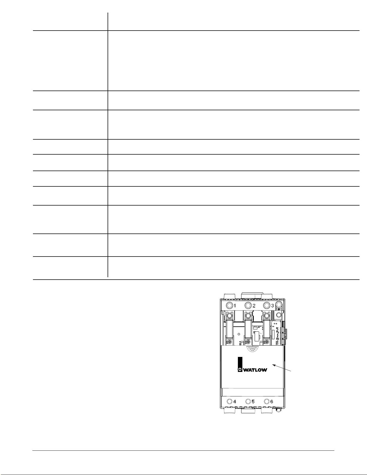
A.6 I Watlow Power Series Appendix
Analog to digital failure error.
Condition For Alarm or Error To OccurAlarm / Error
[`err] System Errors
Heater Bakeout Overcurrent = 0x0001
SCR Short = 0x0002
System Configuration = 0x0004
AD Reference Fail = 0x0008
Checksum Error = 0x0010
Ram Error = 0x0020
Over Temperature Error = 0x0040
Half Cycle Loss = 0x0080
Phase Rotation = 0x0100
Any system-level errors that are active will be represented in binary. As an example, if the power source
is losing half cycles and an over temperature condition exists, Modbus register 195 will contain 0x00C0.
Over temperature Error = 0000000001000000
Half Cycle Loss = 0000000010000000
[`err] Heater Bakeout
[HbOC] Overcurrent Error
Error will occur when the maximum heater current during heater bakeout has been
exceeded.
[`err] Shorted SCR Error
[shrt]
The shorted SCR error is detected by measuring current when the SCR is de-energized
and comparing this reading to the current measured when the SCR is energized. A shorted
SCR error is activated if the de-energized current reading is at least 10A and 25% or more
of the energized current reading.
[`err] System Configur-
[shrt] ation Error
Invalid hardware configuration error.
[`err] Analog to Digital
[``Ad] Failure Error
Incorrect phasing. Error will occur on a three-phase system with a [3L`d] load or on a
multizone (PC8 and PC9) operating on a three-phase power supply under phase angle control if the phasing is incorrect. Must be A,B,C phase rotation (CW).
[`err] Half Cycle Line
[HCyl] Loss Error
Error will occur if a load half cycle loss is detected during five consecutive zone restart
attempts.
[`err] Phase Rotation
[p | ` rOt] Error
[`err] Over Temperature
[``Ot] Error
Error will occur when heat sink temperature is greater than factory shutdown temperature
[`sdÇ].
[`err] Ram Error
[ram]
Error will occur when RAM failure is detected.
[`err] Checksum Error
[`Che]
Invalid checksum in non-volatile memory error.
Checking and Replacing Fuses
Ensure that all high voltage power is off. Slide the fuse cover
down. Using an ohmmeter, measure the dc resistance of the fuse to
determine if it is open. (Typical dc resistance is less than 1 ohm.)
If fuse is open, replace it by removing the old fuse using a 1/2 inch
socket and a #3 Phillips screwdriver. Be careful not to drop washers off
the bolt or screw ends. If they have dropped into the case, shake them
out gently.
The bolt will have 2 washers. The bottom machine screw will have
2 or 3 washers, depending on the size of the SCR in the unit. It is
important that the washers are replaced in the exact order
in which they were removed. Take care installing the fuse so
that its orientation matches the image that is printed on the PC
board.
With the new Cooper Bussman fuse in the unit, torque the bolt to 44
inch-pounds and the screw as follows: For models PXX-F20X-XXXX
and PXX-N20X-XXXX torque to 26 in.-lbs. (2.93 Nm.). For models
PXX-F25X-XXXX, PXX-N25X-XXXX, PXX-F30X-XXXX, PXX-F35XXXXX, and PXX-N30X-XXXX, torque to 44 in.-lbs. (4.95 Nm.). Close
fuse cover. If unit was taken off the wall, observe all terminal torque
specs when reconnecting wires. Unit should now be ready to resume
operation. Reapply power to the controller and line/load terminals.
Fuse
Fuse
Fuse
Fuse
Cover
Power Series
Solid State Power Control
Figure A.6 — Fuse location.
Note: The fuse must be a Cooper Bussman to
retain SCCR rating.
Page 61
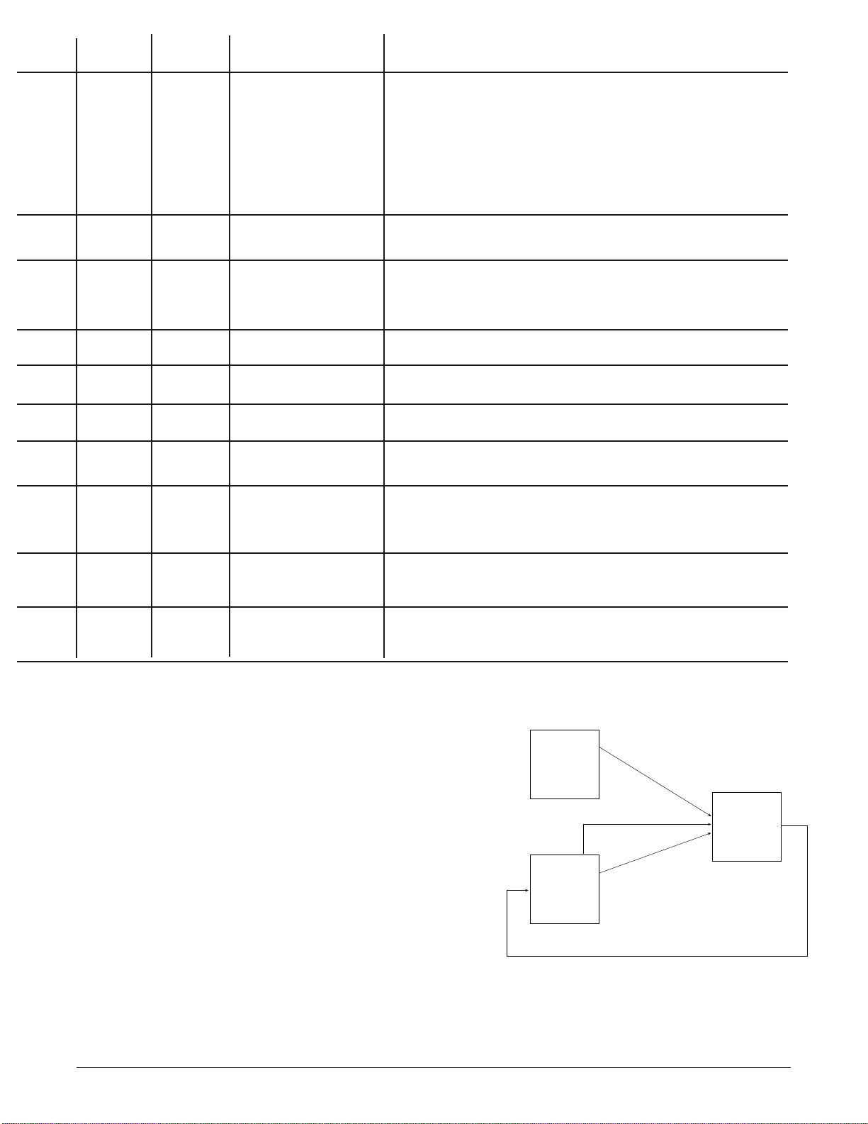
Power Series Backup
There are three prompts which allow the user to manipulate the
EEPROM contents: Backup Data Set, Default Data Set, and Restore
Data Set. Each of these prompts have a choice of [`all], [`sys],
[2n`1], [2n`2], or [2n`3].
There are two sets of data stored in the controller; the first is the
User EEPROM and it is what is read on every power on. The
second is the Backup EEPROM.
The Default Data Set prompt will update the chosen configuration
parameters in the User EEPROM to values that are listed in the
manual as default. It will update the chosen input and retransmit
calibration parameters in the User EEPROM to the values that are
stored in the Backup EEPROM by the factory.
The Backup Data Set prompt will update the chosen configuration
parameters in the Backup EEPROM from the current values stored
in the User EEPROM. It will NOT overwrite the calibration
parameters.
The Restore Data Set prompt will update the chosen configuration
parameters in the User EEPROM from the current values stored in
the Backup EEPROM. It will NOT overwrite the calibration
parameters.
Appendix Watlow Power Series I A.7
Cycle control power. If problem persists, return to factory for repair.
See individual errors below for recommendations.
Cycle control power. If problem persists, return to factory for repair.
195 r, (8)
No
Yes
Corrective ActionModbus Number
Auto
Recovery
Shutdown
195 r
No
Yes
Yes
No
195 r, (1)
It’s likely the heater is too wet for heater bakeout time selected. Increase
heater bakeout time, cycle power to restart heater bakeout process.
Yes No 195 r, (2)
Check output with test instrument while Power (%) [`Out] is at
[``)0]. If there is an output, return to the factory for a new SCR. If
there is no output, check current calibration.
Yes
No
195 r, (4)
Cycle control power. If problem persists, return to factory for repair.
Yes
No
195 r, (128)
Line voltage is losing half cycles or SCR is not gating properly. If
load is inductive, increase [rdLY] until error no longer occurs. Cycle
control power to clear error.
Yes No 195 r, (256)
Three phase power is connected with incorrect phasing. Swap any
two incoming phases. Cycle control power to clear error message.
Yes
No
195 r, (64)
Provide more cabinet ventilation or cooling. Check the fan; if faulty,
return to factory for repair. Check to see that the heat sink is clean.
Cycle control power to clear error. Return to factory for SCR voltage
drop and thermistor evaluation.
Yes
No
Cycle control power. If problem persists, return to factory for repair.
Yes
No
195 r, (16)
195 r, (32)
Figure A.7 — Power Series
Default
Values
Backup
EEPROM
Default Values
Default Prompt
Calibration Defaults
Default Prompt
Restore Prompt
Current Values (not calibration)
Current Values (not calibration)
Backup Prompt
User
EEPROM
Page 62

A.8 ■ Watlow Power Series Appendix
1 Unit Serial Number High Digits
2 Unit Serial Number Low Digits
4 Software Version
5 Manufactured Date (yymm)
7 Hardware Version
30 Software Build Number
50 Unit Current Rating (Amps)
51 Unit Voltage Rating (Volts)
52 Number Zones Configured
53 Hardware Configured Type
54 Configuration Installed Options
55 Power Control Algorithm Select
56 Fixed Time Base (Sec)
57 Factory Safety Shutdown Temp
58 Load Type Select (Control Zone 1 only,
3 Phase only.)
80 Voltage Compensation (On/Off)
85 Comms Watchdog Select (On/Off)
86 Comms Watchdog Timeout (S)
87 Comms Watchdog Failure Output Power
Select
150 Analog (mA) Input 1 Signal
151 Analog (V) Input 1 Signal
152 Line Potential (Volts) rms Line 1
153 A/D Counts Input 1
154 Load Current (Amps) rms Line 1
155 Single Phase 0.1 kVA Zone 1
156 Load Power (kVA) Zone 1
157 Heater Bakeout Timeout Zone 1
159 Output 1 Power (%)
160 Analog (mA) Input 2 Signal
161 Analog (V) Input 2 Signal
162 Line Potential (Volts) rms Line 2
163 A/D Counts Input 2
164 Load Current (Amps) rms Line 2
165 0.1 kVA Zone 2
166 Load Power (kVA) Zone 2
167 Heater Bakeout Timeout Zone 2
169 Output 2 Power (%)
170 Analog (mA) Input 3 Signal
171 Analog (V) Input 3 Signal
172 Line Potential (Volts) rms Line 3
173 A/D Counts Input 3
174 Load Current (Amps) rms Line 3
175 0.1 kVA Zone 3
176 Load Power (kVA) Zone 3
177 Heater Bakeout Timeout Zone 3
179 Output 3 Power (%)
180 Active Alarms
181 Heater Open alarm
182 Heater Tolerance Alarm
183 Heat Sink Over Temperature Alarm
184 Line Loss Alarm
185 Phase Balance Alarm
186 Load Balance Alarm
187 Frequency Out of Tolerance Alarm
188 Line Compensation Alarm
189 Line Over Voltage Alarm
190 Communications Watchdog Alarm
195 Active Errors
198 Line Frequency (Hz)
850 Active Relay State
851 Global Alarm Configuration
860 Heater Open Alarm Config.
861 Heater Tolerance Alarm Config.
862 Over Temperature Alarm Config.
863 Line Loss Alarm Configuration
864 Phase Balance Alarm Config.
865 Load Balance Alarm Config.
866 Frequency Out of Tolerance Alarm
Configuration
867 Voltage Compensation Alarm Config.
868 Over Voltage Alarm Config.
869 Comms Watchdog Alarm Configuration
870 Retransmit Config. Select
871 Retransmit Type Select
872 Retransmit Phase Select
873 Retransmit Zone Select
876 Minimum Amps Retransmit
877 Maximum Amps Retransmit
878 Minimum kVA Retransmit
879 Maximum kVA Retransmit
880 Set Retransmit Output Low Voltage (Volts)
881 Set Retransmit Output High Voltage (Volts)
882 Set Retransmit Output Low Current (mA)
883 Set Retransmit Output High Current (mA)
950 Restore Data Set
951 Backup Data Set
952 Default Data Set
959 Enable NVOL Storage
990 Heat Sink Alarm Temp
991 Load Balance Percentage
1350 Global Lockout
1351 Control Setup Menus Lockout
1352 Options Setup Menus Lockout
1353 Alarms Setup Menu Lockout
1354 Comms Setup Menu Lockout
1355 Retransmit Setup Menu Lockout
1356 Analog Input Factory Menus Lockout
1357 Retransmit Cal Factory Menu Lockout
1358 System Data Factory Menu Lockout
1359 Diagnostics Factory Menu Lockout
1513 Display Test
1540 Line Loss Alarm, Most Recent Type, Line 1
1541 Line Loss Alarm, Previous Type, Line 1
1542 Line Loss Alarm, Least Recent Type, Line 1
1543 Line Loss Alarm, Most Recent Type, Line 2
1544 Line Loss Alarm, Previous Type, Line 2
1545 Line Loss Alarm, Least Recent Type, Line 2
1546 Line Loss Alarm, Most Recent Type, Line 3
1547 Line Loss Alarm, Previous Type, Line 3
1548 Line Loss Alarm, Least Recent Type, Line 3
1555 Retransmit Set Test Word
1560 to 1573 Read Selected A/D Counts
1580 Select Discrete Input
1581 Read Selected Input Value
1590 Heat Sink Temp (°C)
1591 Record High Heat Sink Temp
1700 Factory Mode Request
1799 Factory Password Entry
1960 Accum Hours (10K - 100M)
1961 Accum Hours (0 - 9999)
5011 Set Analog Input Low Current Scale (mA)
Zone 1
5012 Set Analog Input High Current Scale (mA)
Zone 1
5013 Set Analog Input Low Voltage Scale (Volts)
Zone 1
5014 Set Analog Input High Voltage Scale (Volts)
Zone 1
5019 Learn Input Request (Hi, Lo) Zone 1
5021 Set Analog Input Low Current Scale (mA)
Zone 2
5022 Set Analog Input High Current Scale (mA)
Zone 2
5023 Set Analog Input Low Voltage Scale (Volts)
Zone 2
5024 Set Analog Input High Voltage Scale (Volts)
Zone 2
5029 Learn Input Request (Hi, Lo) Zone 2
5031 Set Analog Input Low Current Scale (mA)
Zone 3
5032 Set Analog Input High Current Scale (mA)
Zone 3
5033 Set Analog Input Low Voltage Scale (Volts)
Zone 3
5034 Set Analog Input High Voltage Scale (Volts)
Zone 3
5039 Learn Input Request (Hi, Lo) Zone 3
5101 Input Signal Method Select (dig, mA, Volt)
Zone 1
5102 Numeric (%) Input 1 Signal
Modbus Register Numbers
Relative Parameter Numbers (For Absolute Numbers, add 40001 to the Relative Number.)
5103 Default Numeric Input Signal (%)
Zone 1
5104 Maximum Rate of Change (%/100msec)
Zone 1
5105 Soft Start Time (Sec) Zone 1
5106 Inductive Load Factor Request Zone 1
5107 Inductive Load Current Zone 1
5110 Heater Bakeout Select (On/Off) Zone 1
5111 Heater Bakeout Select Time Zone 1
5112 Current Limit Select (On/Off) Zone 1
5113 Current Limit Set Point (A) Zone 1
5114 Low Tolerance Set Point (A) Zone 1
5115 High Tolerance Set Point (A) Zone 1
5116 Heater Bakeout Overcurrent Trip Zone 1
5201 Input Signal Method Select (dig, mA,
Volt) Zone 2
5202 Numeric (%) Input 2 Signal
5203 Default Numeric Input Signal (%)
Zone 2
5204 Maximum Rate of Change (%/100msec)
Zone 2
5205 Soft Start Time (Sec) Zone 2
5206 Inductive Load Factor Request Zone 2
5207 Inductive Load Current Zone 2
5210 Heater Bakeout Select (On/Off) Zone 2
5211 Heater Bakeout Select Time Zone 2
5212 Current Limit Select (On/Off) Zone 2
5213 Current Limit Set Point (A) Zone 2
5214 Low Tolerance Set Point (A) Zone 2
5215 High Tolerance Set Point (A) Zone 2
5216 Heater Bakeout Overcurrent Trip Zone 2
5301 Input Signal Method Select (dig, mA,
Volt) Zone 3
5302 Numeric (%) Input 3 Signal
5303 Default Numeric Input Signal (%)
Zone 3
5304 Maximum Rate of Change (%/100msec)
Zone 3
5305 Soft Start Time (Sec) Zone 3
5306 Inductive Load Factor Request Zone 3
5307 Inductive Load Current Zone 3
5310 Heater Bakeout Select (On/Off) Zone 3
5311 Heater Bakeout Select Time Zone 3
5312 Current Limit Select (On/Off) Zone 3
5313 Current Limit Set Point (A) Zone 3
5314 Low Tolerance Set Point (A) Zone 3
5315 High Tolerance Set Point (A) Zone 3
5316 Heater Bakeout Overcurrent Trip Zone 3
5411 Adjust Low mA Cal Point Zone 1
5412 Adjust High mA Cal Point Zone 1
5413 Adjust Low V Cal Point Zone 1
5414 Adjust High V Cal Point Zone 1
5415 Calibrate Analog Input Request Zone 1
5421 Adjust Low mA Cal Point Zone 2
5422 Adjust High mA Cal Point Zone 2
5423 Adjust Low V Cal Point Zone 2
5424 Adjust High V Cal Point Zone 2
5425 Calibrate Analog Input Request Zone 2
5431 Adjust Low mA Cal Point Zone 3
5432 Adjust High mA Cal Point Zone 3
5433 Adjust Low V Cal Point Zone 3
5434 Adjust High V Cal Point Zone 3
5435 Calibrate Analog Input Request Zone 3
5591 Baseline Voltage Learn Request Zone 1
5592 Baseline Voltage Learn Request Zone 2
5593 Baseline Voltage Learn Request Zone 3
5594 Baseline Voltage Read/Adjust Zone 1
5595 Baseline Voltage Read/Adjust Zone 2
5596 Baseline Voltage Read/Adjust Zone 3
5700 Cal Retransmit Request
5710 Retransmit Cal mA Low
5711 Retransmit Cal mA High
5720 Retransmit Cal Volts Low
5721 Retransmit Cal Volts High
Page 63

Specifications (2214)
Power Bases
• Single phase, (2 SCRs)
• 3 phase, 2-leg control, (4 SCRs)
Resistive load only, zero cross firing only
• 3 phase, 3-leg control, (6 SCRs)
• 3 phase, 3-leg control, (6 SCRs) for 4 wire wye loads
• Multizone, two and three single phase zones
Output Control Options
• Zero cross contactor, VÎ(dc) input
• Zero cross control, fixed time base
• Time base 1 or 4 seconds with digital programmer
• Zero cross control, variable time base
• Phase angle control and phase angle control with current limit
(not for 3 phase, 2-leg models)
• Soft start factory default 4 seconds upon power-up, and
adjustable from 0.0 to 120 seconds
• Soft start upon input signal change, output rate of change
adjustable to limit max rate of change from 0.1 to 100% per 0.1
second. Factory default 10%.
• Current transformer included when required
• Line voltage compensated (variable time base and phase angle
controllers only)
• Standby or non-operational mode
Output Voltage and Current Rating
• 24VÅ(ac) to 120VÅ(ac)(+10%, -15%)
• 200VÅ(ac) to 480VÅ(ac)(+10%, -15%)
• 200VÅ(ac) to 600VÅ(ac)(+10%, -15%)
• 65 through 250 amps per pole, model dependent; see Output
Amperage Chart and Rating Curves
• Minimum load 1 amp rms ac
• Typical leakage current 5mA
• SCCR 200KA with fusing recommendations on page 3.6.
Alarms
• Single alarm relay
• Latching or non-latching
• Alarm silencing (inhibit) on power up for alarm
• Alarm indication LEDs, shorted SCR, open heater, fuse
• Electromechanical relay, form C contact, software configurable
• Minimum load current 10mA @ 5VÎ(dc)
• Rated resistive loads: 3 amps @ 250VÅ(ac) or 30VÎ(dc) max.,
inductive load rating 1.5 amps with a power factor ≥ 0.4 without
contact suppression
Heater Bakeout
• For single phase (phase to neutral) and 3 phase 6 SCR models
only (not for 3 phase, 2-leg models)
• Soft start with over current trip, runs until programmed bakeout
time expires, then goes zero cross or phase angle firing. Factory
default of 24 hours.
• Adjustable 0 - 9999 minutes with over current trip
• Internal current transformer included
Command Signal Input
Analog
• DC contactor 3.5 to 10VÎ(dc), must turn off at 2.5VÎ(dc)
• Field selectable linear voltage and current of low and high points
within 0-20mA and 0-10VÎ(dc)
• Manual control through front panel
• Factory default 0-20mA input
• Voltage input impedance 11kΩ nominal
• Current input impedance 100Ω nominal
Digital
• On-board digital programmer/display and optional serial communications
Retransmit
• Field selectable and scalable within 0-20mA , 800Ω maximum
load or 0-10VÎ(dc), 1KΩ minimum load.
The default is 4-20mA.
• Resolution:
mA ranges = 5μA nominal
VÎ(dc) = ranges 2.5mV nominal
• Calibration accuracy:
mA ranges = ±20μA
VÎ(dc) ranges = ±10mV
• Temperature Stability: 100ppm°C
Appendix Watlow Power Series I A.9
Digital Programmer/Display and
Communications Capabilities
• Programming functions
• Adjust input and output control type, alarms and soft start.
Heater bakeout and current limit prompts also.
• Monitoring functions
• Display input and output values along with actual output current
• Data retention of digital programmer/display upon power failure
via nonvolatile memory
Serial Communications
• RS-232 for single drop control
• EIA-485 for single or multidrop control
• 32 units maximum can be connected. With additional 485
repeater hardware, up to 247 units may be connected
• Isolated
• Modbus™ RTU protocol
• 1200, 2400, 4800, 9600, 19200 baud rates
• Data format 8 data bits, no parity, one stop bit
Controller Power Supply
• Universal line voltage input range 100 to 240VÅ(ac) (+10%, -15%)
@ 55VA maximum
• 50/60Hz ± 5% line frequency independent
• Controller line voltage for electronic power supply can be run on
separate line voltage
Natural Convection and Fan Cooled Models
• Cabinet venting may be required
Power Dissipation (Watts)
• Approximately 1.25 watts/amp per controlled leg
Isolation
• Command signal to load and line/load to ground
2200VÅ(ac) minimum
• On-board semiconductor fuses provide SCR protection
Mounting
• Back panel mount on F35 models
• Other amperage ratings: Removable mounting plate
• Heat sink fins must be mounted in vertical orientation
High Current Terminals
• Touch safe
• 3/8 inch Allen head compression terminals will accept #6 AWG to
350 MCM wire. Allen wrench adapter (included) for 3/8 inch
socket, or 10 mm, 6 point only.
• Torque to 180 in.-lbs. (20.3 Nm.)
• Wire strip to 30 mm (1-1/8 inch)
Controller Terminals
• Touch safe
• 2.5 mm (1/8 inch) blade screwdriver, accepts 12-22 AWG or 2 No.
22-18 AWG wires.
• Torque to 8 in.-lbs. (0.9 Nm.)
• Wire strip to 6 mm (0.24 inch)
• Requires 90C wire insulation rating on line and load terminals.
Operating Environment
• 50°C (122°F) base rating
• 0 to 60°C (32 to 140°F) fan cooled
• 0 to 65°C (32 to 149°F) natural convection cooled
• 0 to 90% RH, non-condensing
• Meets EN50178, Pollution degree 3
Storage Temperature
• -40 to 85°C (-40 to 185°F)
Dimensions
• Width x height x depth
191 mm x 354 mm x 200 mm on N20 through F30 models
(7.5 in x 14.0 in x 7.9 in)
337 mm x 421 mm x 234.1 mm on F35 models
(13.3 in x 16.6 in x 9.2 in)
Shipping Weight
• 10.3 kg. (23 lbs.) on N20 through F30 models
• 17.2 kg. (38 lbs.) on F35 models
Agency Approvals
• UL 508 and C-UL listed, file #E73741
• CE marked, see Declaration of Conformity on page A.14
Page 64
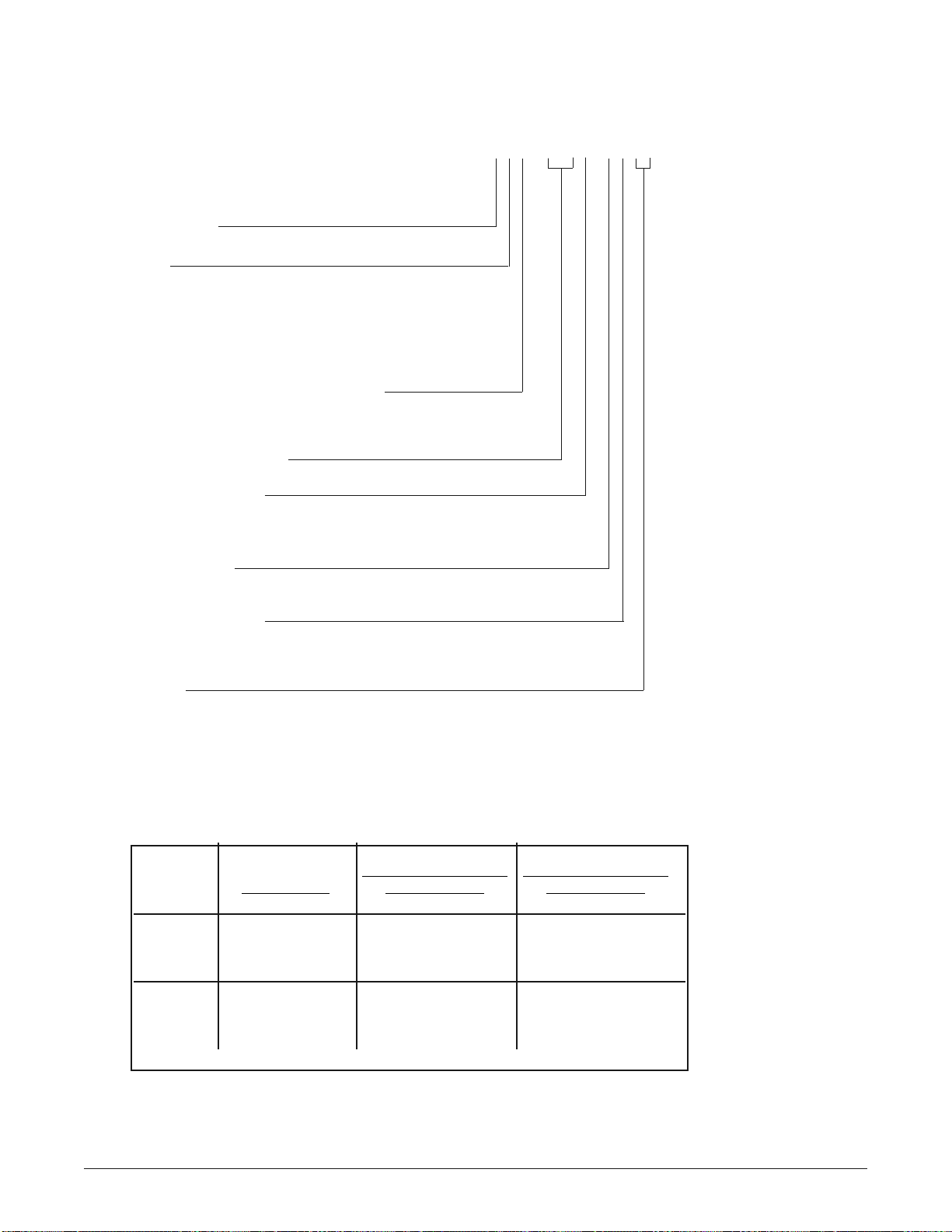
Ordering Information
(1528)
To order, complete the code number
to the right with the information below:
P C _ _ - _ _ _ _ - _ _ _ _
Power Series = Microprocessor-Based
Solid State Power Controller
Package Style
C=65 to 250 Amps
Phase
1=1-phase
2=3-phase, 2-leg control (4 SCRs)
3=3-phase, 3-leg control (6 SCRs)
4=3-phase, 4-wire, wye connected load
8 = 2 single-phase zones (specify 01 or 03 for Custom)
9=3 single-phase zones (specify 01 or 03 for Custom)
Heater Diagnostics (includes current limit)
0=None
1=Heater Diagnostics (Current Limiting and Heater Bakeout
are only available on single-phase and 3-phase, 3-leg Controllers)
Output Amperage Rating
(See Amperage Chart below; insert code number here.)
Output Voltage Rating
A=24 to 120V~
B=200 to 480V~
C=200 to 600V~
Communications
0=None
1=EIA/TIA 232/485 communications, isolated (field selectable)
Feedback/Retransmit
0=None
1=Load current feedback (0 to 10V or 0 to 20mA scalable retransmit output)
(Must have heater diagnostics selected.)
Custom
00 = None
AA = No Watlow logo with agency approval marks
AB - ZZ = Custom, consult factory for options
01 = Select for PC8 or PC9 using single-phase power supply, Watlow logo
03 = Select for PC8 or PC9 using multi-phase power supply, Watlow logo
IMPORTANT NOTES:
Phase Angle:
Phase angle and phase
angle with current limit
are available on single
phase, and 3 phase/3-leg
models only. To get
current limiting, you
must also order heater
diagnostics.
Heater Bakeout:
Heater bakeout is
available on single
phase, and 3 phase/3-leg
models with heater
diagnostics.
Amperage Chart @ 50°C (122°F)
2 Single Phase Zones 3 Single Phase Zones
Single Phase 3 Phase, 2-Leg 3 Phase, 3-Leg
Code Amperage Code Amperage Code Amperage
Non N20 100A N20 80A N20 65A
Fan Cooled N25 140A N25 105A N25 85A
N30 165A N30 120A N30 105A
F20 125A F20 120A F20 90A
Fan Cooled F25 200A F25 160A F25 140A
F30 250A F30 185A F30 155A
F35 250A F35 225A
NOTE: User documentation may be available in French, German, Spanish, Italian, and Dutch, as well as English. Check Watlow’s website
(www.watlow.com/) for availability.
NOTE: See semiconductor fuses and holders on pages 2.1 and 3.6.
A.10 I Appendix Watlow Power Series
Page 65

Appendix Watlow Power Series ■ A.11
Index
A
A to D Failure Error A.4
Accum Hours (0 - 9999) 6.18
Accum Hours (10K - 100M) 6.18
Active Alarms 6.1
Active Relay State 6.10
Adjust High mA Cal Point Zones 1-3
6.21
Adjust High V Cal Point Zones 1-3 6.21
Adjust Low mA Cal Point Zones 1-3
6.21
Adjust Low V Cal Point Zones 1-3 6.21
Alarms 5.7
active relay state 5.7
global 5.7
latched 5.7
latched and silenced 5.7
silencing 5.7
standard 5.7
Alarms Setup Menu Lockout 6.16
Alarms, troubleshooting A.4-A.5
communications watchdog alarm A.4
frequency out of tolerance alarm A.4
heat sink over temperature alarm A.4
heater open alarm A.4
heater tolerance alarm A.4
line compensation alarm A.4
line loss alarm A.4
line over voltage alarm A.4
load balance alarm A.4
phase balance alarm A.4
Ambient Temperature Rating 2.1
Analog (mA) Input 1 Signal 6.2, 6.3
Analog (mA) Input 2 Signal 6.2, 6.3
Analog (mA) Input 3 Signal 6.3
Analog (mA) Input Signal 6.1
Analog (V) Input 1 Signal 6.2, 6.3
Analog (V) Input 2 Signal 6.2, 6.3
Analog (V) Input 3 Signal 6.3
Analog (V) Input Signal 6.1, 6.4
Analog Input Factory Menus Lockout 6.16
B
Backup A.7
Backup Data Set 6.15
Baseline Voltage 5.6
Baseline Voltage Learn Req.
Zones 1-3
6.7
Baseline Voltage Read/Adj.
Zones 1-3
6.7
C
Cal Retransmit Request 6.22
Calibrate Analog Input Req.
Zones 1-3
6.21
Calibrate Analog Input Signal
Zones 1-3
Menus
6.21
Calibrate Retransmit
Menu
6.22
Comms Setup Menu Lockout 6.16
Comms Watchdog Alarm Config. 6.11
Communications 5.8
Communications Watchdog Alarm A.4
Configuration Installed Options 6.18
Control Configurations 1.2
3 phase, 2-leg 1.2
3 phase, 3-leg 1.2
3 phase, multizone 1.2
single phase 1.2
Control Setup Menus Lockout 6.16
Cooling 2.3
Current Limit Select (On/Off)
Zones 1-3
6.8
Current Limit Set Point (A)
Zones 1-3
6.9
Current Limiting 5.5
D
DC Contactor - Zero Cross 5.2
Default Data Set 6.15
Default Numeric Input Sig. (%)
Zones 1-3
6.6
Diagnostics Factory Menu Lockout 6.17
Diagnostics
Menu 6.19
-6.20
Dimensions 2.2
Display Loop Errors 6.1, A.4-A.7
Display Loop Menu 4.2, 4.3
Display Phase Selection 1-3 6.4
Display Test 6.20
Display Zone Selection 6.2, 6.3
E
Enable NVOL Storage 6.16
Enclosure Guidelines 2.3
Errors, troubleshooting
A.4-A.5
A to D failure error A.4
half cycle line loss error A.6
heater bakeout overcurrent error A.4
nonvolatile memory checksum error A.6
over temperature error A.6
phase rotation error A.6
RAM error A.6
shorted SCR error A.4
system configuration error A.4
F
Factory Mode 6.20
Factory Mode Request 6.20
Factory Page Menu 4.2, 4.4
Factory Page Parameters 6.14 - 6.22
Factory Password 6.20
Factory Password Entry 6.20
Factory Safety Shutdown Temp 6.18
Fan Cooled Output Rating Curves 2.5
Fast Start Guide 5.10
Fixed Time Base (Sec) 6.5
Fixed Time Base - Zero Cross 5.1
Frequency Out of Tol. Alarm Config. 6.11
Frequency Out of Tolerance Alarm A.4
Fuse Replacement A.6
G
Global Alarm Configuration 5.7, 6.10
Global Lockout 5.6, 6.16
Global/Menu Lockouts Menu
6.16-6.17
H
Half Cycle Line Loss Error A.6
Hardware Version 6.17
Harsh Environment 2.3
Heat Sink Alarm Temp 6.18
Heat Sink Over Temperature Alarm A.4
Heat Sink Over Temperature Alarm
Configuration 6.10
Heat Sink Over Temperature Alarm
Temperature 6.10
Heat Sink Temp (°C) 6.18
Heater Bakeout 5.4
Heater Bakeout Overcurrent Error A.4
Heater Bakeout Overcurrent Trip
Zones 1-3 6.8
Heater Bakeout Select (On/Off) Zones 1-3
6.8
Heater Bakeout Select Time Zones 1-3 6.8
Heater Bakeout Timeout 6.2
Heater Bakeout Timeout Zone 1 6.2, 6.3
Heater Bakeout Timeout Zone 2 6.2, 6.3
Heater Bakeout Timeout Zone 3 6.3
Heater Diagnostics Feature 1.2
Heater Open Alarm A.4
Heater Open Alarm Config. 6.10
Heater Tolerance Alarm A.4
Heater Tolerance Alarm Config. 6.10
Heater Tolerance Detection 5.4
High Tolerance Set Point (A) Zones 1-3
6.9
I J
Inductive Current 6.9
Inductive Load Factor Request 6.9
Input 5.6
signal selection 5.6
Input Signal Method Select (dig, mA, Volt)
Zones 1-3 6.6
Input Wiring 3.2-3.3
2 zone 3.3
3 zone 3.3
communications 3.2
control power and alarm 3.2
retransmit 3.2
single zone 3.3
Installation 2.1-2.6
K
Keys and Displays 4.1
L
Learn Input Learn Req. (Hi, Lo) Zones 1-3
6.7
Line Compensation Alarm A.4
Line Frequency (Hz) 6.1
Line Loss Alarms 6.19, A.4
Line Loss Alarm Configuration 6.10
Line Over Voltage Alarm A.4
Line Potential (Volts) rms Zone 1 6.3, 6.4
Line Potential (Volts) rms Zone 2 6.3, 6.4
Line Potential (Volts) rms Zone 3 6.3, 6.4
Line Potential (Volts) rms 6.2
Line Power Wiring 3.4
Line Voltage Compensation 6.6
Load Activity Indicator 6.1
Load Balance Alarm A.4
Load Balance Alarm Config. 6.11
Load Balance Percentage 6.11
Load Current (Amps) rms 6.2
Load Current (Amps) rms Zone 1
6.3, 6.4
Load Current (Amps) rms Zone 2 6.3, 6.4
Load Current (Amps) rms Zone 3 6.4
Load Power (kVA) 6.2, 6.4
Load Power (kVA) Zone 1 6.3, 6.4
Page 66

A.12 ■ Appendix Watlow Power Series
Load Power (kVA) Zone 2 6.3, 6.4
Load Power (kVA) Zone 3 6.4
Load Type Select (Control Zone 1
only, 3 phase only.) 6.7
Low Tolerance Set Point (A) Zone 1-3
6.9
M
Maintenance 2.4
Manufactured Date (yymm) 6.17
Maximum Amps Retransmit 6.13
Maximum kVA Retransmit 6.13
Maximum Rate of Change 5.3
adjustable on signal change 5.3
Maximum Rate of Change
(%/100msec) Zone 1-3 6.8
Menu Lock 5.6
Minimum Amps Retransmit 6.13
Minimum kVA Retransmit 6.13
Model Number A.10
Mounting 2.2-2.3
N
Natural Convection Output Rating
Curves 2.6
Navigation and Software 4.1-4.4
Nonvolatile Memory Checksum Error
A.4
Number Zones Configured 6.18
Numeric (%) Input 1 Signal 6.2, 6.3, 6.4
Numeric (%) Input 2 Signal 6.2, 6.3, 6.4
Numeric (%) Input 3 Signal 6.3, 6.4
Numeric (%) Input Signal 6.1
O
Options Setup Menus Lockout 6.16
Output 1 Power (%) 6.2, 6.3, 6.4
Output 2 Power (%) 6.2, 6.3
Output 3 Power (%) 6.2, 6.3
Output Power (%) 6.2, 6.4
Output Rating Curves 2.5-2.6
Output Wiring 3.4-3.5
3 phase, 2-leg, 4 SCR 3.4
3 phase, 3-leg,6 SCR, 4-wire wye 3.5
3 phase, 3-leg, SCR/diode hybrid 3.5
multizone 3.5
single phase 3.4
Over Temperature Error A.6
Over Voltage Alarm Config. 6.11
P Q
Phase Angle 5.2
Phase Balance Alarm A.4
Phase Balance Alarm Config. 6.11
Phase Rotation Error A.6
Power Control Algorithm Select 6.5
Prompt Index A.13
R
RAM Error A.6
Read Selected Analog to Digital
Counts 6.19
Read Selected Input Value 6.20
Record High Heat Sink Temp 6.18
Removing the Power Series 2.4
Restore Data Set 6.15
Retransmit 5.9
Retransmit Cal Factory Menu
Lockout 6.16
Retransmit Cal mA High 6.22
Retransmit Cal mA Low 6.22
Retransmit Cal Volts High 6.22
Retransmit Cal Volts Low 6.22
Retransmit Config. Select 6.12
Retransmit Phase Select 6.13
Retransmit Set Test Word 6.20
Retransmit Setup Menu Lockout 6.16
Retransmit Type Select 6.12
Retransmit Wiring 3.2
Retransmit Zone Select 6.13
S
Safety Information inside front cover
Select Analog to Digital Channel 6.19
Select Discrete Input 6.20
Set Analog Input High Cur. (mA)
Zone 1-3 6.6
Set Analog Input High Volt. (Volts)
Zone 1-3 6.7
Set Analog Input Low Cur. (mA)
Zone 1-3 6.6
Set Analog Input Low Volt. (Volts)
Zone 1-3 6.6
Set Retransmit Output High Cur. (mA)
6.13
Set Retransmit Output High Volt. (Volts)
6.14
Set Retransmit Output Low Cur. (mA) 6.13
Set Retransmit Output Low Volt. (Volts) 6.14
Setup Alarms Configuration Menu 6.10-
6.11
Setup Comms Configuration Menu 6.12
Setup Control Algorithm 6.5
Setup Control Zone 1, 2, and 3 Menus
6.6-6.7
Setup Options Zone 1, 2, and 3 Menus
6.8-6.9
Setup Page Menu 4.2, 4.4
Setup Page Parameters 6.5 - 6.13
Setup Page Select 6.5
Setup Retransmit Configuration Menu
6.12-6.14
Shorted SCR Error A.4
Signal Selection 5.6
Soft Start 5.3
adjustable on power up 5.3
Soft Start Time (Sec) Zones 1-3 6.8
Software Build Number 6.17
Software Version 6.17
Specification A.9
System Configuration Error A.4
System Data Factory Menu Lockout 6.17
System Data Manipulation
Menu
6.15
T
Technical Assistance inside front cover
Torque 3.1, 3.2, 3.4
Troubleshooting A.2-A.3
Troubleshooting Alarms and Errors
A.4-A.7
U V
Unit Address Select 6.12
Unit Baud Rate Select 6.12
Unit Current Rating (Amps) 6.18
Unit Information Menu 6.17-18
Unit Serial Number High Digits 6.17
Unit Serial Number Low Digits 6.17
Unit Voltage Rating (Volts) 6.17
Variable Time Base - Zero Cross 5.2
Voltage Compensation Alarm Config. 6.11
W X Y Z
Warnings and Cautions inside front
cover
Warranty Information back cover
Watchdog Failure Output Power Select
6.12
Watchdog Select (On/Off) 6.12
Watchdog Timeout 6.12
Wire Bending Radius 2.1
Wire Stripping 3.1, 3.2, 3.4
Wiring 3.1-3.6
input 3.2-3.3
output 3.4-3.5
Wiring Example 3.6
Your Comments inside front cover
Zero Cross 5.1
Page 67

Appendix Watlow Power Series ■ A.13
Prompt Index
A
[``Ad] Select Analog to Digital Channel 6.19
[Addr] Unit Address Select 6.12
[ALÇ`] Heat Sink Alarm Temp 6.18
[aLÇ`] Heat Sink Over Temperature Alarm
Temperature 6.10
[a| lgc] Active Relay State 6.10
[ALgo] Power Control Algorithm Select 6.5
[Algo] Setup Control Algorithm Menu 6.5-
6.6
{`Alr} Alarms Setup Menu Lockout 6.16
[`ALr] Setup Alarms Configuration Menu 5.7,
6.10-6.11
B
[baud] Unit Baud Rate Select 6.12
[BAuP] Backup Data Set 6.15
[bl`U] Baseline Voltage Read/Adjust 6.7
C
[```Ç] Heat Sink Temperature (°C) 6.18
[CALA] Calibrate Analog Input Request 6.21
[CALr] Cal Retransmit Request 6.22
[`Cf9] Retransmit Configuration Select 6.12
{`CIn} Analog Input Factory Menus Lockout
6.16
[CIn1] [CIn2] [CIn3] Calibrate Analog Input
Signal Zone 1, 2, or 3 Menus 6.21-6.22
[CL`A] Current Limit Set Point (A) 5.5, 6.9
[`CLi] Current Limit Select (On/Off) 5.5, 6.8
{COM} Comms Setup Menu Lockout 6.16
[COM] Setup Comms Configuration Menu
6.12
[Cnts] Read Selected Analog to Digital
Counts 6.19
[cont] dc contactor 5.2
[C| rtr] Retransmit Cal Factory Menu Lockout
6.16
[Crtr] Calibrate Retransmit Menu 6.22
[`Ctr] Control Setup Menus Lockout 6.16
[Ctr1] [Ctr2] [Ctr3] Setup Control Zone 1,
2, and 3 Menus 6.6-6.8
[`Cur] Load Current (Amps) rms 6.2
[Cur1], [Cur2], [Cur3] Load Current (Amps)
rms 6.3, 6.4
[Cur–] Maximum Amps Retransmit 6.13
[Cur_] Minimum Amps Retransmit 6.13
[C| Wd] Comms Watchdog Alarm Configura-
tion 6.11
D
[dAtA] System Data Factory Menu Lockout
6.17
[dATA] System Data Manipulation Menu
6.15-6.16
[date] Manufactured Date (yymm) 6.17
[dFLt] Default Data Set 6.15
[dFlt] Default Numeric Input Signal (%) 6.6
[diAg] Diagnostics Factory Menu Lockout 6.17
[diag] Diagnostics Menu 6.19-6.20
[dIsp] Display Test 6.20
EF
[fcty] Factory Mode Request 6.20
[Fcty] Factory Page 6.14 - 6.22
[Freq] Frequency Out of Tolerance Alarm
Configuration 6.11
[FrEq] Line Frequency (Hz) 6.1
[`FTB] Fixed Time Base 5.1
[`FTB] Fixed Time Base (Sec) 6.5
G
[glbl] Global Alarm Configuration 5.7, 6.10
{gLOC} Global Lockout 5.6, 6.16
H
[`HbC] Heater Bakeout Overcurrent Trip
6.8
[`Hbo] Heater Bakeout Select (On/Off) 5.4,
6.8
[`Hbt] Heater Bakeout Timeout 6.2
[Hbt1] [Hbt2] [Hbt3] Heater Bakeout Time-
out 6.2, 6.3
[HI`Ç] Record High Heat Sink Temp 6.18
[HrS–] Accum Hours (10K - 100M) 6.18
[HrS_] Accum Hours (0 - 9999) 6.18
[`HUa] Load Power (kVA) 6.2, 6.4
HUA–] Maximum kVA Retransmit 6.13
[HUA_] Minimum kVA Retransmit 6.13
[HUa1] [HUa2] [HUa3] Load Power (kVA) 6.3,
6.4
[HUer] Hardware Version 6.17
I J K
[ICur] Inductive Current 6.9
[``In] Analog (mA or V) or Numeric (%)
Input Signal 6.1, 6.4
[``In] Input Signal Method Select (dig, mA,
volt) 6.6
[``In] Select Discrete Input 6.20
[In`1], [In`2], [In`3] Analog (mA or V) or
Numeric (%) Input Signal 6.2, 6.3
[Indf] Inductive Load Factor Request 6.9
[Info] Unit Information Menu 6.17-6.18
L
[l!a1] Line Loss Alarm, Most Recent 6.19
[l!a2] [l@a2] [l#a2] Line Loss 6.19
[l!a3] [l@a3] [l#a3] Alarm Type 6.19
[l@a1] Line Loss Alarm, Previous 6.19
[l#a1] Line Loss Alarm, Least Recent 6.19
[Lbal] Load Balance Alarm Config. 6.11
[Ldif] Load Balance Percentage 6.11
[Line] Line Loss Alarm Config. 6.10
[LoAd] Load Activity Indicator 6.1
[`LOC] Global/Menu Lockouts Menu 6.16-6.17
[lrn| A] Learn Input Learn Request (Hi, Lo)
6.7
[lrn| U] Baseline Voltage Learn Request 6.7
M N
[Min] Heater Bakeout Select Time 5.4, 6.8
[nna–] Adjust High mA Cal Point 6.21
[nna_] Adjust Low mA Cal Point 6.21
[nna–] Retransmit Cal mA High 6.22
[nna_] Retransmit Cal mA Low 6.22
[nna–] Set Analog Input High Current (mA)
6.6
[nna_] Set Analog Input Low Current (mA)
6.6
[nUOL] Enable NVOL Storage 6.16
O
[Open] Heater Open Alarm Config. 6.10
[`OPt] Config. Installed Options 6.18
{`Opt} Options Setup Menus Lockout 6.16
[Opt1] [Opt2] [Opt3] Setup Options Zone 1,
2, and 3 Menus 6.8-6.9
[``OT] Heat Sink Over Temperature Alarm
Configuration 6.10
[``OU] Over Voltage Alarm Config. 6.11
[`Out] Output Power (%) 6.2, 6.4
[Out1], [Out2], [Out3] Output Power (%)
6.2, 6.3
P Q
[p| bAl] Phase Balance Alarm Config. 6.11
[Phas] Display Phase 6.4
[PhaS] Retransmit Phase Select 6.13
[Ph2t] Phase Angle 5.2
[`PW] Factory Password 6.20
[`PW] Factory Password Entry 6.20
[PWr] Watchdog Failure Output Power
Select (%) 6.12
R
[ratA] Unit Current Rating (Amps) 6.18
[rATE] Maximum Rate of Change (%/100msec)
6.8
[ratU] Unit Voltage Rating (Volts) 6.17
[rdLY] Reactance Delay 6.8
[reSt] Restore Data Set 6.15
[rEtr] Retransmit Set Test Word 6.20
{retr} Retransmit Setup Menu Lockout 6.16
[rEtr] Setup Retransmit Configuration Menu
6.12-6.14
[rt| C–] Set Retransmit Output High Current
(mA) 6.13
[rt| C_] Set Retransmit Output Low Current
(mA) 6.13
[rt| U–] Set Retransmit Output High Voltage
(Volts) 6.14
[rt| U_] Set Retransmit Output Low Voltage
(Volts) 6.14
S
[Sbld] Software Build Number 6.17
[sdÇ`] Factory Safety Shutdown Temp 6.18
[`seC] Watchdog Timeout (Sec) 6.12
[`Set] Setup Page Select 6.5-6.13
[`Sn–] Unit Serial Number High Digits 6.17
[`Sn_] Unit Serial Number Low Digits 6.17
[Soft] Soft Start 5.3
[Soft] Soft Start Time (Sec) 6.8
[SUEr] Software Version 6.17
T
[`tol] Heater Tolerance Alarm Configuration
6.10
[tol–] High Tolerance Set Point (A) 6.9
[tol_] Low Tolerance Set Point (A) 6.9
[type] Load Type Select 6.7
[type] Retransmit Type Select 6.12
U V W X Y Z
[`UAL] Read Selected Input Value 6.20
[``UC] Line Voltage Compensation 6.6
[``UC] Voltage Compensation Alarm
Configuration 6.11
[`UoL] Line Potential (Volts) rms 6.2
[Uol1], [Uol2], [Uol3] Line Potential (Volts)
rms 6.3, 6.4
[Uol–] Adjust High V Cal Point 6.21
[Uol_] Adjust Low V Cal Point 6.21
[Uol–] Retransmit Cal Volts High 6.22
[Uol_] Retransmit Cal Volts Low 6.22
[Uol–] Set Analog Input High Voltage (Volts)
6.7
[Uol_] Set Analog Input Low Voltage (Volts)
6.6
[Urtb] Variable Time Base 5.2
[`Wd] Watchdog Select (On/Off) 6.12
[2onC] Number Zones Configured 6.18
[2one] Retransmit Zone Select 6.13
[2one] Zone Display Selection 6.2, 6.3
Page 68
%FDMBSBUJPOPG$POGPSNJUZ
1PXFS4FSJFT1PXFS$POUSPMMFS
8"5-088JOPOB*OD
#VOEZ#PVMFWBSE
8JOPOB.JOOFTPUB64"
%FDMBSFTUIBUUIFGPMMPXJOHQSPEVDU&OHMJTI
%FTJHOBUJPO
1PXFS4FSJFT1PXFS$POUSPMMFS
.PEFM/VNCFST1$PSPS///'''PS'
"#PS$PSPSPS"";;
$MBTTJGJDBUJPO4PMJE4UBUF1PXFS$POUSPMMFS$MBTT**1PMMVUJPO%FHSFF***
3BUFE7PMUBHFUP7_
3BUFE'SFRVFODZ )[
.FFUTUIFFTTFOUJBMSFRVJSFNFOUTPGUIFGPMMPXJOH&VSPQFBO6OJPO%JSFDUJWFTVTJOHUIFSFMFWBOU
TFDUJPOTPGUIFOPSNBMJ[FETUBOEBSETBOESFMBUFEEPDVNFOUTTIPXO
&$&MFDUSPNBHOFUJD$PNQBUJCJMJUZ%JSFDUJWF
&/ &MFDUSJDBMFRVJQNFOUGPSNFBTVSFNFOUDPOUSPMBOEMBCPSBUPSZVTF&.$
SFRVJSFNFOUT(SPVQ$MBTT"
&/&MFDUSPTUBUJDEJTDIBSHF
&/&MFDUSJDBMGBTUUSBOTJFOUT
&/.BHOFUJDGJFMET
&/3BEJBUFEJNNVOJUZ
&/$POEVDUFEJNNVOJUZ
&/4VSHFJNNVOVOJUZ
&/7PMUBHFEJQTTIPSUJOUFSSVQUJPOTBOEWPMUBHFWBSJBUJPOTJNNVOJUZ
&/7$FMMVMBSQIPOF
/PUF6TFPGBOFYUFSOBMGJMUFSJTSFRVJSFEUPDPNQMZXJUI&/DPOEVDUFE
FNJTTJPOMJNJUT4FFQBHFSFWFSTFGPSJOGPSNBUJPOBOEJOTUSVDUJPOT
/PUF"-JOF*NQFEBODF4UBCJMJ[BUJPO/FUXPSL-*4/OPUBMJOFDMBNQXBTVTFEGPS
BMMFNJTTJPOTUFTUJOH
&$-PX7PMUBHF%JSFDUJWF
&/&MFDUSPOJDFRVJQNFOUGPSVTFJOQPXFSJOTUBMMBUJPOT
5IF1IBTF"OHMF$POUSPM.PEFPQUJPOGPS1PXFS4FSJFTJTFYDMVEFEGSPNUIJTEFDMBSBUJPO
%ÊDMBSFRVFMFQSPEVJUTVJWBOU'SBOÉBJT
%ÊTJHOBUJPO#MPDEFQVJTTBODF1PXFS4FSJFT
/VNÊSPEFNPEÍMF1$PVPV///'''PV'
$MBTTJGJDBUJPO#MPDTEFQVJTTBODFÆTFNJDPOEVDUFVST1FSUVCBUJPOT$MBTTF**%FHSÊ***
5FOTJPOOPNJOBMF Æ7_
'SÊRVFODFOPNJOBMF)[
4POUDPOGPSNFTBVYQSJODJQBMFTOPSNFTEFTEJSFDUJWFTEFM6OJPO&VSPQÊFOOFBVSFHBSEEFMBEFT
TFDUJPOTQFSUJOFOUFTEFTOPSNFTTUBOEBSETFUEPDVNFOUTBQQBSFOUÊTQSÊTFOUÊT
&$%JSFDUJWFEFDPNQBUJCJMJUÊÊMFDUSPNBHOÊUJRVF
&/"QQBSFJMMBHFÊMFDUSJRVFQPVSMBNFTVSFMBDPNNBOEFFUMVTBHF
EFMBCPSBUPJSFm1SFTDSJQUJPOTSFMBUJWFTÆMB$PNQBUJMJUÊ&MFDUSP
.BHOÊUJRVFHSPVQFDMBTTF"
&/%ÊDIBSHFÊMFDUSPTUBUJRVF
&/5SBOTJUPJSFTSBQJEFTÊMFDUSJRVFT
&/$IBNQTNBHOÊUJRVFT
&/*NNVOJUÊSBZPOOÊF
&/*NNVOJUÊDPOEVJUF
&/&TTBJEJNNVOJU°BVYPOEFTEFDIPD
&/&TTBJTEJNNVOJUÊSFMBUJGTBVYDSFVYEFUFOTJPODPVQVSFTCSÍWFTFU
WBSJBUJPOTEFUFOTJPO
&/ *OTFOTJCJMJUÊBVYTVSUFOTJPOT
&/ *OTFOTJCJMJUÊBVYDIVUFTTVCJUFTBVYDPVSUFTJOUFSSVQUJPOTFUBVY
WBSJBUJPOTEFUFOTJPO
&/75ÊMÊQIPOFDFMMVMBJSF
3FNBSRVF*MFTUOÊDFTTBJSFEVUJMJTFSVOGJMUSFFYUFSOFQPVSTFDPOGPSNFSBVYMJNJUFT
EÊNJTTJPOQBSDPOEVDUJPOEFMBOPSNF&/7PJSMFTJOGPSNBUJPOTFU
JOTUSVDUJPOTBVWFSTP
3FNBSRVF6OSÊTFBVEFTUBCJMJTBUJPOEhJNQÊEBODFEFMJHOF34*-FUOPOQBTVOF
MJNJUFEFDIBNQBÊUÊVUJMJTÊQPVSUPVTMFTUFTUTEhÊNJTTJPO
&$%JSFDUJWFEFCBTTFUFOTJPO
&/&RVJQFNFOUÊMFDUSPOJRVFVUJMJTÊTVSEFTJOTUBMMBUJPOTÊMFDUSJRVFT
-FTCMPDTEFQVJTTBODFFOWFSTJPOBOHMFEFQIBTFOFTPOUQBTDPVWFSUTQBSDFUUFEÊDMBSBUJPO
&SLMÅSUEBEBTGPMHFOEF1SPEVLU%FVUTDI
#FTDISFJCVOH1PXFS4FSJFT5IZSJTUPS-FJTUVOHTTUFMMFS
.PEFMMOVNNFSO1$PEFSPEFS///'''PEFS'"#
PEFS$PEFSPEFSPEFS"";;
,MBTTJGJLBUJPO)BMCMFJUFS-FJTUVOHTTUFMMFS*OTUBMMBUJPOTLBUFHPSJF**&NJTTJPOTHSBE***
/FOOTQBOOVOH7_
/FOOGSFRVFO[)[
&SGÛMMUEJFXJDIUJHTUFO/PSNFOEFSGPMHFOEFO"OXFJTVOHEFS&VSPQÅJTDIFO(FNFJOTDIBGUVOUFS
7FSXFOEVOHEFTXJDIUJHFO"CTDIOJUUTEFSOPSNBMJTJFSUFO4QF[JGJLBUJPOFOVOEEFSVOUFOTUFIFOEFO
FJOTDIMÅHJHFO%PLVNFOUF
&$&8(&MFLUSPNBHOFUJTDIF7FSUSÅHMJDILFJU
&/ &MFLUSPHFSÅUF[VS.FTTVOH3FHFMVOHVOE[VN-BCPSFJOTBU[&.$
3JDIUMJOJFO(SVQQF,MBTTF"
&/&MFLUSPTUBUJTDIF&OUMBEVOH
&/&MFLUSJTDIFTDIOFMMF4UÕF
&/.BHOFUJTDIF'FMEFS
&/4USBIMVOHTJNNVOJUÅU
&/-FJUVOHTJNNVOJUÅU
&/4QBOOVOHTTUPJNNVOJUÅU
&/ *NNVOJUÅUHFHFO4QBOOVOHTHFGÅMMFLVS[F6OUFSCSFDIVOHFOVOE
4QBOOVOHTBCXFJDIVOHFO
&/7.PCJMUFMFGPO
)JOXFJT%JF7FSXFOEVOHFJOFTFYUFSOFO'JMUFSTLBOOFSGPSEFSMJDITFJOVNEFS&/
4JFIF4FJUF3ÛDLTFJUFGÛS*OGPSNBUJPOFOVOE"OXFJTVOHFO
)JOXFJT;VS&NJTTJPOTNFTTVOHXVSEFFJO-FJUVOHTJNQFEBO[
4UBCJMJTJFSVOHTOFU[XFSL
-*4/LFJOF,MFNNFFJOHFTFU[U
&$&8(/JFEFSTQBOOVOHTSJDIUMJOJF
&/&MFLUSPOJTDIF(FSÅUFGÛSEJF7FSXFOEVOHCFJ4UBSLTUSPNJOTUBMMBUJPOFO
-FJTUVOHTTUFMMFSNJU1IBTFOBOTDIOJUUTTUFVFSVOHTJOEWPOEJFTFS&SLMÅSVOHBVTHFTDIMPTTFO
%FDMBSBRVFFMQSPEVDUPTJHVJFOUF&TQBÒPM
%FTJHOBDJÓO$POUSPMBEPSEF1PUFODJB1PXFS4FSJFT
/ÙNFSPTEF.PEFMPT1$PP///'''P'"#P$
PPP"";;
$MBTJGJDBDJÓO$POUSPMBEPSEF1PUFODJBEF&TUBEP4ÓMJEP$MBTF**(SBEP$POUBNJOBUF***
5FOTJÓOOPNJOBM %FB7
'SFDVFODJBOPNJOBM )[
$VNQMFDPOMPTSFRVJTJUPTFTFODJBMFTEFMBTTJHVJFOUFT%JSFDUJWBTEFMB6OJÓO&VSPQFB
VTBOEPMBTTFDDJPOFTQFSUJOFOUFTEFMBTSFHMBTOPSNBMJ[BEBTZMPTEPDVNFOUPTSFMBDJPOBEPT
RVFTFNVFTUSBO
&$%JSFDUJWBEF$PNQBUJCJMJEBE&MFDUSPNBHOÊUJDB
&/ &RVJQPFMÊUSJDPQBSBNFEJDJÓODPOUSPMZVTPFOMBCPSBUPSJPT3FRVJTJUPT
EFDPNQBUJCJMJEBEFMFDUSPNBHOÊUJDB(SVQP$MBTF"
&/%FTDBSHBFMFDUSPTUÃUJDB
&/1FSUVSCBDJPOFTUSBOTJUPSJBTFMÊDUSJDBTSÃQJEBT
&/$BNQPTNBHOÊUJDPT
&/*ONVOJEBESBEJBEB
&/*ONVOJEBEDPOEVDJEB
&/ 4PCSFUFOTJÓO
&/$BÎEBTEFUFOTJÓOJOUFSSVQDJPOFTCSFWFTZWBSJBDJPOFTEFUFOTJÓO
&/75FMÊGPOPQPSUÃUJM
/PUB4FSFRVJFSFMBVUJMJ[BDJÓOEFVOGJMUSPFYUFSOPQBSBDVNQMJSDPOMBOPSNB
&/EFMÎNJUFTEFFNJTJÓODPOEVDJEPT-ÊBTFMBQÃHJOBSFWFSTP
QBSBPCUFOFSNÃTJOGPSNBDJÓOFJOTUSVDDJPOFT
/PUB&OUPEBTMBTQSVFCBTEFNFEJDJÓOEFFNJTJPOFTTFFNQMFÓVOB-*4/
TJHMBTFOJOHMÊTEFSFEEFFTUBCJMJ[BDJÓOEFJNQFEBODJBEFMÎOFBZOP
VOFTUBCJMJ[BEPSEFMÎOFB
&$%JSFDUJWBEFCBKBUFOTJÓO
&/&RVJQPFMFDUSÓOJDPQBSBVTBSFOJOTUBMBDJPOFTEFHFOFSBDJÓOEFHFOFSJB
4FFYDMVZFEFFTUBEFDMBSBDJÓOMBPQDJÓOEF.PEPEF$POUSPMQPS"OHVMPEF'BTFEFM
$POUSPMBEPS1PXFS4FSJFT
3BZNPOE%'FMMFS***8JOPOB.JOOFTPUB64"
/BNFPG"VUIPSJ[FE3FQSFTFOUBUJWF1MBDFPG*TTVF
(FOFSBM.BOBHFS.BSDI
5JUMFPG"VUIPSJ[FE3FQSFTFOUBUJWF%BUFPG*TTVF
@@@@@@@@@@@@@@@@@@@@@@@@@@@@@@@@@@@@@@@@
4JHOBUVSFPG"VUIPSJ[FE3FQSFTFOUBUJWF
1FS&$8&&&%JSFDUJWF1MFBTF3FDZDMF1SPQFSMZ
5IFTFEFWJDFTDPOUBJOMFBETPMEFSBOEBSFOPU3P)4DPNQMJBOU
5IFZBSFB$POUSPM%FWJDFBOEGBMMPVUTJEFUIFTDPQFPG&$%JSFDUJWF
7FVJMMF[SFDZDMFSMFNBUÊSJF MDPOGPSNÊNFOUÆMB%JSFDUJWF8&&&$&
$FTEJTQPTJUJGTDPOUJFOOFOUEFMBCSBTVSFBVQMPNCFUOFTPOUQBTDPOGPSNFTÆMB
EJSFDUJWF3P)4*MTBHJUEFEJTQPTJUJGTEFDPOUSÔMFRVJOFSFOUSFQBTEBOTMFDBESF
EFMB%JSFDUJWF&$
1FS&$8&&&%JSFLUJWF#JUUFPSEOVOHTHFNÅSFDZDMFO
%JFTF(FSÅUFFOUIBMUFO#MFJMPUVOETJOEOJDIU3P)4LPOGPSN&TIBOEFMUTJDIVN4UFVFSVOHTHFSÅUF
EJFOJDIUVOUFSEJF3JDIUMJOJF&(GBMMFO
3FDJDMBSDPSSFDUBNFOUFTFHÙOMBEJSFDUJWB8&&&&$
&TUPTEJTQPTJUJWPTUJFOFOTPMEBEVSBEFQMPNPZOPDVNQMFODPOMBEJSFDUJWB3P)44PO
EJTQPTJUJWPTEFDPOUSPMZOPFTUÃOSFHJEPTQPSMBEJSFDUJWB&$
"#PV$PVPVPV"";;
A.14 I Appendix Watlow Power Series
Page 69
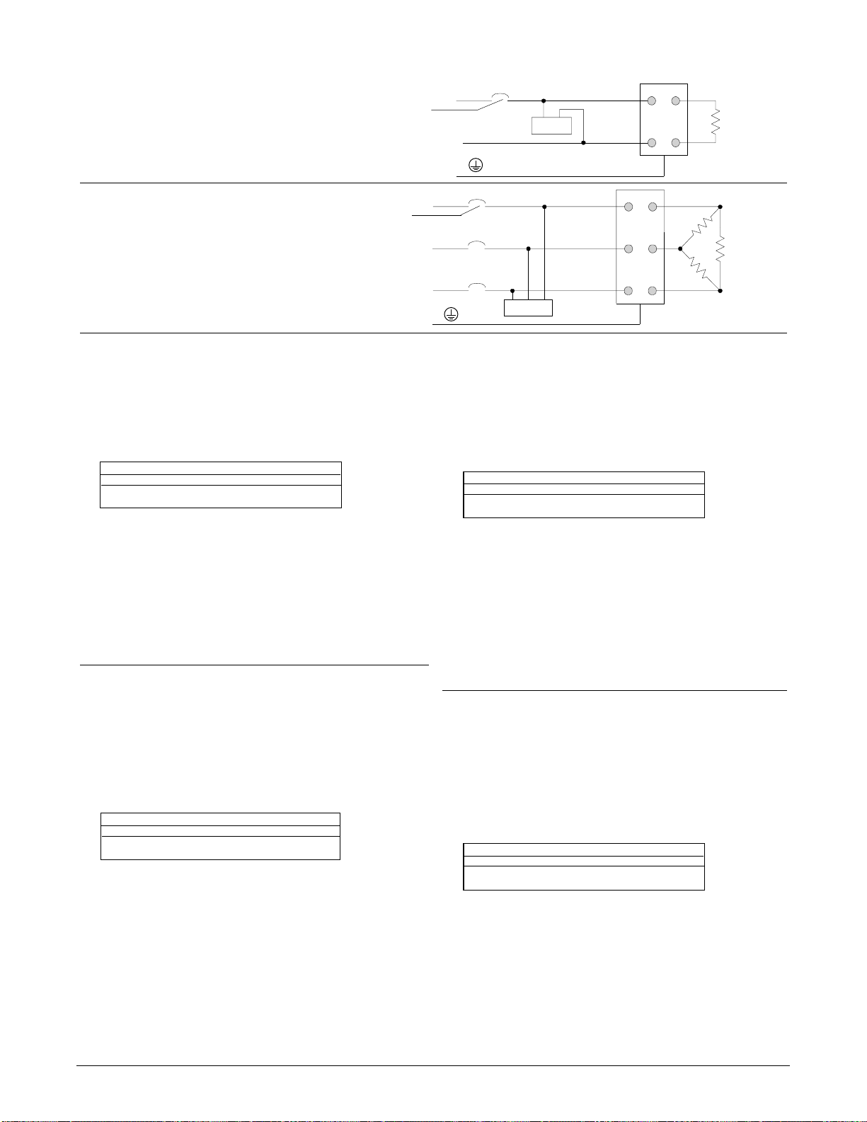
Watlow Power Series Appendix ■ A.15
Figure 1- Tank Filter, 1Ø 230V~
Abbildung 3. Tankfilter 1Ø; 230 V~
Figure 1 - Filtre cylindrique, 1Ø 230V~
Figura 1 - Filtro de tipo tanque, 1Ø 230V~
Figure 2- Tank Filter, 3Ø 440V~
Abbildung 3. Tankfilter 3Ø; 440 V~
Figure 2 - Filtre cylindrique, 3Ø 440V~
Figura 2 - Filtro de tipo tanque, 3Ø 440V~
Note 1: Protective earth (PE) connection required to minimize EMI.
Hinweis 1: Schutzerdung (PE) erforderlich, um EMI auf ein Minimum zu halten.
Remarque 1 : connexion de terre protectrice (PE) requise pour minimiser l’interférence EMI.
Nota 1: Conexión a tierra de protección (PE) requerida para minimizar la interferencia electromagnética (EMI).
Breakers or Disconnect
Unterbrecher oder Trenner
Coupe-circuit
Cortacircuitos o desconexión
Breakers or Disconnect
Unterbrecher oder Trenner
Coupe-circuit
Cortacircuitos o desconexión
PE
A
B
C
A
N
PE
See Note 1
Siehe Hinweis 1
Voir remarque 1
Ver Nota 1
See Note 1
Siehe Hinweis 1
Voir remarque 1
Ver Nota 1
Crydom
Crydom
Power Series
Power Series
2
341
Heater
Last
Elément chauffant
2
451
63
Calentador
Heater
Last
Elément chauffant
Calentador
Required (EN61326) External EMI Filters for
An external EMI filter must be used in conjunction with the Power Series.
Power Series with
Watlow has verified that one type of filter will suppress electromagnetic interference (EMI)
created by the Power Series power controller to within the EN61326 requirements:
1) A tank filter supplied by Crydom, installed across the power lines, suppresses EMI on the
power lines. See Figures 1 and 2.
Wiring illustrations for the filters appear on the right. See Table 1 for the correct filter:
Description Filter # Watlow #
1Ø; 230V~ 1F25 14-0019
3Ø; 440V~ 3F20 14-0020
Table 1 - Power Series EMI Filters
Crydom
≥ 6A Loads
WARNING:
The tank filter specified may suppress desirable communications carried on power lines
in the 150 to 250 kHz region. The filter may suppress carrier current such as that used for
infant monitors and medical alert systems. Verify that suppressed carrier current or other
desirable communications on power lines creates no hazard to people or property.
Failure to observe this warning could result in damage to property, and injury or death for
personnel.
WARNING:
All filter installation and wiring must be performed by qualified personnel, and conform to
local and national electrical codes. Failure to observe this warning could result in damage
to property, and injury or death for personnel.
Filtres externes EMI (EN61326) requis pour
les Power Series‚ à des charges de ≥ 6A
Un filtre externe EMI doit être utilisé conjointement avec le Power Series.
Watlow s’est assuré qu’un type de filtre supprimera l’interférence électromagnétique (EMI) créée
par le bloc de puissance Power Series, afin de se conformer aux exigences de la norme
EN61326 :
1) Un filtre cylindrique, fourni par Crydom, installé sur les lignes secteurs, supprime
l’interférence EMI des lignes secteurs. Voir les figures 1 et 2.
Les illustrations de câblage des filtres figurent à droite. Voir le tableau 1 sur l’utilisation du filtre
approprié :
Description N° de Filtre N° Watlow
1Ø; 230V~ 1F25 14-0019
3Ø; 440V~ 3F20 14-0020
Tableau 1 : Filtres EMI Power Series
Crydom
IMPORTANT :
Le filtre spécifié peut supprimer les communications désirables de lignes secteurs se
situant entre 150 et 250 kHz. Le filtre peut supprimer le courant porteur, tel que celui
utilisé sur les appareils de surveillance des nouveaux-nés et les systèmes d’alerte
médicale. S’assurer que le courant porteur supprimé ou toute autre communication sur
les lignes secteurs ne crée pas de danger pour les personnes ou les installations. La nonobservation de cet avertissement peut entraîner des dommages matériels, des blessures
ou même la mort.
IMPORTANT :
Toute l’installation et tout le câblage du filtre doivent être réalisés par un personnel
qualifié et être en conformité avec les réglementations électriques locales et nationales.
La non-observation de cet avertissement peut entraîner des dommages matériels, des
blessures ou même la mort.
Erforderliche Entstörfilter gemäß EN 61326 für
Ein externer EMI-Filter sollte mit dem Power Series.
Power Series mit Laststrom
Watlow hat nachgewiesen, daß eine Filterart die elektro-magnetischen Störungen, die durch
den Leistungssteller der Bauart Power Series hervorgerufen werden, der Norm EN61326
entsprechend unterdrückt.
1) Ein Tankfilter von Crydom, welcher über die Stromleitungen installiert wird, unterdrückt die
elektro-magnetischen Störungen auf den Stromleitungen. Siehe Abbildungen 1 und 2.
Schaltschemata für die Filter sind auf der rechten Seite zu sehen. Den richtige Filter finden Sie
in Tabelle 1:
Beschreibung Filter Nummer Watlow Nummer
1Ø; 230V~ 1F25 14-0019
3Ø; 440V~ 3F20 14-0020
Tabelle 1. Power Series EMI-Filter
Crydom
≥ 6A.
WARNUNG:
Der angegebene Entstörfilter kann gewünschte Datenübertragungen im Bereich von 150
bis 250 kHz unterdrücken. Der Filter kann den Trägerstrom, der zum Beispiel bei
Überwachungsgeräten für Kleinkinder oder medizinischen Warnsystemen verwendet
wird, unterdrücken. Stellen Sie sicher, daß die Ünterdrückung des Trägerstroms oder
anderer gewünschter Datenübertragungen auf den Stromleitungen keine Gefahr für
Personen oder Sachen darstellt. Eine Nichtbeachtung dieser Sicherheitsmaßnahme kann
Sachschäden, Verletzungen oder den Tod zur Folge haben
WARNUNG:
Alle Filterinstallationen und Verdrahtungen müssen von qualifiziertem Personal
durchgeführt werden und den bestehenden elektrischen Vorschriften entsprechen. Das
Nichtbeachten dieser Warnung kann zu Sachschäden, Verletzungen oder zum Tod des
Personals führen.
Filtros de interferencia electromagnética (EMI) externos (EN61326)
requeridos para Power Series con cargas ≥ 6A
Se debe usar un filtro de EMI externo junto con el Power Series.
La empresa Watlow ha verificado que hay un tipo de filtro que suprimen la interferencia
electromagnética (EMI) creada por el controlador de potencia Power Series, y la mantiene
dentro de los límites establecidos por los requerimientos de la EN61326:
1) Al instalarse un filtro de tipo tanque provisto por Crydom en paralelo con las líneas de
alimentación eléctrica se suprime la interferencia electromagnética (EMI) en ellas. Véanse
las Figuras 1 y 2.
Las ilustraciones de los cableados para los filtros aparecen en la derecha. Véase la Tabla 1
para seleccionar el filtro correcto:
Descripción No. de filtro No. Watlow
1Ø; 230V~ 1F25 14-0019
3Ø; 440V~ 3F20 14-0020
Tabla 1 - Filtros de EMI de Power Series
Crydom
¡Advertencia!
El filtro de tipo tanque especificado puede suprimir ciertas comunicaciones deseables que se
envían por las líneas de alimentación eléctrica en frecuencias que van desde 150 a 250 kHz. El
filtro puede suprimir corrientes portadoras, como las que se usan para monitores para bebés y
sistemas de alarma médica. Verifique que la corriente portadora u otras comunicaciones
deseadas suprimidas en las líneas de alimentación eléctrica no presenten peligros para las
personas o la propiedad. El no observar esta advertencia puede causar daños a la propiedad, y
lesiones o muerte del personal.
¡Advertencia!
Todas las instalaciones y conexiones de filtros deben ser realizadas por personal
calificado y en conformidad con los códigos locales y nacionales. El no observar esta
advertencia puede causar daños a la propiedad, y lesiones o muerte del personal.
Page 70

A.16 ■ Appendix Watlow Power Series
Display Loop
(See the Power Series User’s Manual)
Setup Page
[algo] Control Algorithm
[ALgo] Power Control Algo Select _ _ _ _ _ _ _
[`FTB] Fixed Time Base _ _ _ _ _ _ _ _ _ _ _ _
[``UC] Line Voltage Comp _ _ _ _ _ _ _ _ _ _ _
[Ctr1] Control Zone 1
[``In] Input Signal Method Select _ _ _ _ _ _
[dFlt] Default Numeric Input Sig _ _ _ _ _ _ _
[nna_] Set Analog Input Lo Cur _ _ _ _ _ _ _ _
[nna–] Set Analog Input Hi Cur _ _ _ _ _ _ _ _
[Uol_] Set Analog Input Lo Volt _ _ _ _ _ _ _ _
[Uol–] Set Analog Input Hi Volt _ _ _ _ _ _ _ _ _
[lrn| a] Learn Input Learn Req _ _ _ _ _ _ _ _ _
[bl`U] Baseline Volt Read/Adj _ _ _ _ _ _ _ _ _
[lrn| U] Baseline Volt Learn Req _ _ _ _ _ _ _ _
[type] Load Type Select _ _ _ _ _ _ _ _ _ _ _ _
[rATE] Max Rate of Change _ _ _ _ _ _ _ _ _ _
[Soft] Soft Start Time _ _ _ _ _ _ _ _ _ _ _ _ _
[Opt1] Options Zone 1
[`Hbo] Heater Bakeout Select _ _ _ _ _ _ _ _ _
[Min] HBO Select Time _ _ _ _ _ _ _ _ _ _ _ _
[`HbC] HBO Current Trip _ _ _ _ _ _ _ _ _ _ _
[`CLi] Cur Limit Select _ _ _ _ _ _ _ _ _ _ _ _ _
[CL`A] Cur Limit Set Point _ _ _ _ _ _ _ _ _ _ _
[tol_] Lo Tol Set Point _ _ _ _ _ _ _ _ _ _ _ _ _
[tol–] Hi Tol Set Point _ _ _ _ _ _ _ _ _ _ _ _ _
[Indf] Induct Load Factor Req _ _ _ _ _ _ _ _
[ICur] Inductive Current _ _ _ _ _ _ _ _ _ _ _ _
[Ctr2] Control Zone 2
[``In] Input Signal Method Select _ _ _ _ _ _
[dFlt] Default Numeric Input Sig _ _ _ _ _ _ _
[nna_] Set Analog Input Lo Cur _ _ _ _ _ _ _ _
[nna–] Set Analog Input Hi Cur _ _ _ _ _ _ _ _
[Uol_] Set Analog Input Lo Volt _ _ _ _ _ _ _ _
[Uol–] Set Analog Input Hi Volt _ _ _ _ _ _ _ _ _
[lrn| a] Learn Input Learn Req _ _ _ _ _ _ _ _ _
[bl`U] Baseline Volt Read/Adj _ _ _ _ _ _ _ _ _
[lrn| U] Baseline Volt Learn Req _ _ _ _ _ _ _ _
[rATE] Max Rate of Change _ _ _ _ _ _ _ _ _ _
[Soft] Soft Start Time _ _ _ _ _ _ _ _ _ _ _ _ _
[Opt2] Options Zone 2
[`Hbo] Heater Bakeout Select _ _ _ _ _ _ _ _ _
[Min] HBO Select Time _ _ _ _ _ _ _ _ _ _ _ _
[`HbC] HBO Current Trip _ _ _ _ _ _ _ _ _ _ _
[`CLi] Cur Limit Select _ _ _ _ _ _ _ _ _ _ _ _ _
[CL`A] Cur Limit Set Point _ _ _ _ _ _ _ _ _ _ _
[tol_] Lo Tol Set Point _ _ _ _ _ _ _ _ _ _ _ _ _
[tol–] Hi Tol Set Point _ _ _ _ _ _ _ _ _ _ _ _ _
[Indf] Induct Load Factor Req _ _ _ _ _ _ _ _ _
[ICur] Inductive Current _ _ _ _ _ _ _ _ _ _ _ _
[Ctr3] Control Zone 3
[``In] Input Signal Method Select _ _ _ _ _ _
[dFlt] Default Numeric Input Sig _ _ _ _ _ _ _
[nna_] Set Analog Input Lo Cur _ _ _ _ _ _ _ _
[nna–] Set Analog Input Hi Cur _ _ _ _ _ _ _ _
[Uol_] Set Analog Input Lo Volt _ _ _ _ _ _ _ _
[Uol–] Set Analog Input Hi Volt _ _ _ _ _ _ _ _ _
[lrn| a] Learn Input Learn Req _ _ _ _ _ _ _ _ _
[bl`U] Baseline Volt Read/Adj _ _ _ _ _ _ _ _ _
[lrn| U] Baseline Volt Learn Req _ _ _ _ _ _ _ _
[rATE] Max Rate of Change _ _ _ _ _ _ _ _ _ _
[Soft] Soft Start Time _ _ _ _ _ _ _ _ _ _ _ _ _
[Opt3] Options Zone 3
[`Hbo] Heater Bakeout Select _ _ _ _ _ _ _ _ _
[Min] HBO Select Time _ _ _ _ _ _ _ _ _ _ _ _
[`HbC] HBO Current Trip _ _ _ _ _ _ _ _ _ _ _
[`CLi] Cur Limit Select _ _ _ _ _ _ _ _ _ _ _ _
[CL`A] Cur Limit Set Point _ _ _ _ _ _ _ _ _ _
[tol_] Lo Tol Set Point _ _ _ _ _ _ _ _ _ _ _ _ _
[tol–]] Hi Tol Set Point _ _ _ _ _ _ _ _ _ _ _ _ _
[Indf] Induct Load Factor Req _ _ _ _ _ _ _ _ _
[ICur] Inductive Current _ _ _ _ _ _ _ _ _ _ _ _
[`ALr] Alarms Configuration
[a| lgc] Active Relay State _ _ _ _ _ _ _ _ _ _ _
[glbl] Global Alarm _ _ _ _ _ _ _ _ _ _ _ _ _ _
[Open] Heater Open Alarm _ _ _ _ _ _ _ _ _ _ _
[`tol] Heater To Alarm _ _ _ _ _ _ _ _ _ _ _ _
[``OT] Heat Sink Over Temp Alarm _ _ _ _ _
[alÇ`] Heat Sink Over Temp Alarm Temp _ _ _
[Line] Line Loss Alarm _ _ _ _ _ _ _ _ _ _ _ _
[p| bAl] Phase Bal Alarm _ _ _ _ _ _ _ _ _ _ _ _
[Lbal] Load Bal Alarm _ _ _ _ _ _ _ _ _ _ _ _
[Ldif] Load Bal Percent _ _ _ _ _ _ _ _ _ _ _ _
[Freq] Freq Out of Tol Alarm _ _ _ _ _ _ _ _ _
[``UC] Volt Comp Alarm _ _ _ _ _ _ _ _ _ _ _ _ _
[``OU] Over Volt Alarm _ _ _ _ _ _ _ _ _ _ _ _
[C| wd] Comms Watchdog Alarm _ _ _ _ _ _ _
[COM] Comms Configurations
[Addr] Unit Address Select _ _ _ _ _ _ _ _ _ _ _ _
[baud] Unit Baud Rate Select _ _ _ _ _ _ _ _ _
[`Wd] Watchdog Select _ _ _ _ _ _ _ _ _ _ _ _ _
[`seC] Watchdog Timeout _ _ _ _ _ _ _ _ _ _ _
[PWr] Watchdog Fail Output Pwr Sel _ _ _ _
[rEtr] Retransmit Configuration
[`Cf9] Retrans Select _ _ _ _ _ _ _ _ _ _ _ _ _
[type] Retrans Type Select _ _ _ _ _ _ _ _ _ _
[PhaS] Retrans Phase Select _ _ _ _ _ _ _ _ _ _
[2one] Retrans Zone Select _ _ _ _ _ _ _ _ _ _ _ _
[Cur_] Min Amps Retrans _ _ _ _ _ _ _ _ _ _ _ _
[Cur–] Max Amps Retrans _ _ _ _ _ _ _ _ _ _ _
[HUA_] Min kVA Retrans _ _ _ _ _ _ _ _ _ _ _ _
HUA–] Max kVA Retrans _ _ _ _ _ _ _ _ _ _ _ _
[rt| C_] Set Retrans Output Lo Cur _ _ _ _ _ _
[rt| C–] Set Retrans Output Hi Cur _ _ _ _ _ _
[rt| U_] Set Retrans Output Lo Volt _ _ _ _ _ _
[rt| U–] Set Retrans Output Hi Volt _ _ _ _ _ _
Factory Page
[dATA] System Data Manipulation
[BAuP] Backup Data Set _ _ _ _ _ _ _ _ _ _ _ _
[dFLt] Default Data Set _ _ _ _ _ _ _ _ _ _ _ _
[rest] Restore Data Set _ _ _ _ _ _ _ _ _ _ _ _
[nUOL] Enable NVOL Storage _ _ _ _ _ _ _ _ _
[`Loc] Global/Menu Lockouts
{gLOC} Global Lockout _ _ _ _ _ _ _ _ _ _ _ _ _
[`Ctr] Control Setup Menus Lock _ _ _ _ _ _ _
{`Opt} Options Setup Menus Lock _ _ _ _ _ _
{`Alr} Alrms Setup Menu Lock _ _ _ _ _ _ _ _
{COM} Comms Setup Menu Lock _ _ _ _ _ _ _
{retr} Retrans Setup Menu Lock _ _ _ _ _ _ _
{`CIn} Analog Input Menu Lock _ _ _ _ _ _ _ _
[C| rtr] Retrans Menu Lock _ _ _ _ _ _ _ _ _ _ _
[dAtA] Sys Data Menu Lock _ _ _ _ _ _ _ _ _ _
[diAg] Diag Menu Lock _ _ _ _ _ _ _ _ _ _ _ _ _
[Info] Unit Information
[`Sn–] Unit Serial # Hi Digits _ _ _ _ _ _ _ _ _
[`Sn_] Unit Serial # Lo Digits _ _ _ _ _ _ _ _ _
[date] Mfg Date _ _ _ _ _ _ _ _ _ _ _ _ _ _ _ _ _
[HUer] Hardware Version _ _ _ _ _ _ _ _ _ _ _ _
[SUEr] Software Version _ _ _ _ _ _ _ _ _ _ _ _
[Sbld] Software Build # _ _ _ _ _ _ _ _ _ _ _ _
[ratU] Unit Volt Rating _ _ _ _ _ _ _ _ _ _ _ _ _
[ratA] Unit Curt Rating _ _ _ _ _ _ _ _ _ _ _ _
[2onC] # Zones _ _ _ _ _ _ _ _ _ _ _ _ _ _ _ _ _
[`OPt] Installed Options _ _ _ _ _ _ _ _ _ _ _ _
[```Ç] Heat Sink Temp _ _ _ _ _ _ _ _ _ _ _ _ _
[ALÇ`] Heat Sink Alarm Temp _ _ _ _ _ _ _ _ _
[sdÇ`] Safety Shutdown Temp _ _ _ _ _ _ _ _ _
[HIÇ`] Hi Heat Sink Temp _ _ _ _ _ _ _ _ _ _ _
[HrS–] Accum Hours _ _ _ _ _ _ _ _ _ _ _ _ _ _
[HrS_] Accum Hours _ _ _ _ _ _ _ _ _ _ _ _ _ _
[diag] Diagnostics
[``Ad] Select A/D Channel _ _ _ _ _ _ _ _ _ _ _
[Cnts] Read Selected A/D Counts _ _ _ _ _ _ _
Line Loss Alarms:
[l!a1] Most Recent _ _ _ _ _ _ _ _ _ _ _ _ _ _ _
[l@a1] Line Loss _ _ _ _ _ _ _ _ _ _ _ _ _ _ _
[l#a1] Alarm Type _ _ _ _ _ _ _ _ _ _ _ _ _ _ _
[l!a2] Previous _ _ _ _ _ _ _ _ _ _ _ _ _ _
[l@a2] Line Loss _ _ _ _ _ _ _ _ _ _ _ _ _ _ _
[l#a2] Alarm Type _ _ _ _ _ _ _ _ _ _ _ _ _ _ _
[l!a3] Least Recent _ _ _ _ _ _ _ _ _ _ _ _ _ _ _
[l@a3] Line Loss _ _ _ _ _ _ _ _ _ _ _ _ _ _ _
[l#a3] Alarm Type _ _ _ _ _ _ _ _ _ _ _ _ _ _
[dIsp] Display Test _ _ _ _ _ _ _ _ _ _ _ _ _ _ _
[``In] Select Discrete Input _ _ _ _ _ _ _ _ _ _
[`UAL] Read Selected Input Value _ _ _ _ _ _ _
[rEtr] Retrans Set Test Word _ _ _ _ _ _ _ _
The Factory Page also includes calibration
parameters that are not necessary for everyday
use of the controller. Calibration parameters and
procedures are explained in the Power Series
User’s manual.
Power Series Software Map
Enter your settings on a
photocopy of this page.
Page 71

Page 72

■ Using the Manual
Watlow Power Series User’s Manual
Watlow Winona, 1241 Bundy Boulevard, P.O. Box 5580, Winona, Minnesota USA 55987-5580,
Phone: +1 (507) 454-5300, Fax: +1 (507) 452-4507
How to Reach Us
Quality and
Mission
Statement:
Watlow Winona will be
the world’s best
supplier of industrial
temperature control
products, services, and
systems by exceeding
our customers’,
employees’, and
shareholders’
expectations.
Contact
• Phone: +1 (507) 454-5300.
• Fax: +1 (507) 452-4507.
• For technical support, ask for an Applications Engineer.
• To place an order, ask for Customer Service.
• To discuss a custom option, ask for the Power Series Product Manager.
Warranty
The Watlow Power Series is warranted to be free of defects in material and
workmanship for 36 months after delivery to the first purchaser for use, providing that the units have not been misapplied. Since Watlow has no control
over their use, and sometimes misuse, we cannot guarantee against failure.
Watlow's obligations hereunder, at Watlow's option, are limited to replacement, repair or refund of purchase price, and parts which upon examination
prove to be defective within the warranty period specified. This warranty does
not apply to damage resulting from transportation, alteration, misuse, or
abuse.
Returns
• Call or fax Customer Service for a Return Material Authorization (RMA)
number before returning a controller.
• Put the RMA number on the shipping label, along with a written description
of the problem.
• A restocking charge of 20% of the net price is charged for all standard units
returned to stock.
Your Authorized Watlow Distributor is:
TOTAL
CUSTOMER
SATISFACTION
3 Year Warranty
 Loading...