

Watlow FIREBAR Circulation Heater User Manual
WATLOW IND. FIREBAR
®
Circulation Heater Installation & Maintenance Manual
I&M Number: 316-42-1-1 Page: 1
Date: 06-11-08 Rev: 2.00
________________________________________________________________________________________________________________________________________________________________________________________________________________________
Pre Installation
• Check to make sure that heater received is the same as that ordered.
• Watlow heaters are built to comply with UL and CSA dielectric requirements, it may be necessary due to
atmospheric conditions / humidity, to perform a dielectric test prior to startup. (Refer to megohm test
under Installation section)
Safety
Electric heaters are inherently dangerous!! Care should be taken to read and completely understand the
Installation and Maintenance manual before installing and wiring the heater. Any installation and
maintenance performed on the heater shall be done by a qualified electrician, in accordance with the
"National Electric Code" and other electrical codes as they apply. It is the users responsibility to ensure that
the heater being used is properly selected and installed in the application.
!
The Caution Symbol (exclamation point) alerts you to a "CAUTION", a safety or
functional hazard which could affect your equipment or its performance.
The warning symbol (lightning bolt) alerts you to a "WARNING", a safety hazard which
Installation
Proper heater selection and installation will result in efficient heat transfer, safe operation, and long heater
life.
1. Megohm precheck
During shipping and/or storage, the possibility of moisture absorption by the insulation material within the
element is possible. To ensure proper megohm values a minimum 500 VDC megohm meter (Megger)
should be used to ensure that the megohm reading between the heater terminal and the heater sheath is
more than 10 megohms when the unit is at room temperature.
If several units are interconnected, the megohm of the heater is obtained by taking the reading and
dividing by the number of interconnected elements. This reading should be greater than 10 megohms.
If a low megohm value exists, two alternative methods can be used to remedy the situation. The best
method is to remove all terminal hardware including thermostat if provided, and bake out the heater at no
higher than 250°F (120°C) overnight or until an acceptable reading is reached.The second method is to
energize the unit at low voltage in air until the megohm is at an acceptable reading. Care should be
taken to prevent the heater sheath from exceeding 750°F (398°C) for Incoloy® and Stainless Steel
elements. Both of these methods should be performed with the heater out of the tank. The orientation of
the heater in relation to the tank should be observed in order to reposition the heater properly.
2. Protection of heater elements from over temperature
The use of temperature controls to regulate heating process and prevent heater over temperature is
highly recommended to ensure safe heater operation. It is the users responsibility to ensure safety of
the installation.
WARNING: Install high temperature control protection in systems where an over temperature
fault condition could present a fire hazard or other hazard. Failure to install temperature control
protection where a potential hazard exists could result in damage to equipment and property,
and injury to personnel.
could affect you and the equipment
WATLOW IND.n # 6 INDUSTRIAL LOOP RD. n HANNIBAL MO, 63401n PHONE 573-221-2816 n FAX 573-221-3723

WATLOW IND. FIREBAR
®
Circulation Heater Installation & Maintenance Manual
I&M Number: 316-42-1-1 Page: 2
Date: 06-11-08 Rev: 2.00
________________________________________________________________________________________________________________________________________________________________________________________________________________________
Failure of components in a temperature control loop, such as the sensor, heater control relay or main
temperature control, can result in damage to a product in process, a melt down of a heater, and / or
damaging fire.
To protect against this possibility, over temperature protection must be provided to interrupt or remove
power from the heater circuit. A bulb and capillary thermostat is not recommended for this function
since it may not respond quickly enough to adequately protect the heater. In cases where the
thermostat bulb gets too hot before the system is turned off, the thermostat bulb could rupture.
This could result in the thermostat remaining in the "ON" condition since there is insufficient
fluid to move contacts apart. We recommend the temperature protection have appropriate third party
approval, and be applied in the classification for which it was tested and approved.
In order to help prevent premature failure and a potentially hazardous condition in cases where
consequences of failure may be severe, use an appropriate third party approved liquid level protection
device. The liquid level should be such that the entire heater is fully submerged with enough liquid above
the heater to adequately dissipate heat from itself as under normal operating conditions. Consult your
local authorized sales representative for specific recommendations for your application.
3. Terminal Enclosures
Terminal enclosures should be selected to be compatible with the environment in which the heater will
be located. It is the users responsibility to determine the need for correct rating of the electrical housing.
This should be based on appropriate national and local electrical codes. Failure to use a compatible
enclosure could result in heater damage and personnel danger.
Standard terminal enclosures are designed for general purpose use and are rated NEMA 1. These
enclosures should be applied where there will be no danger of spilled liquids, dampness, dirt, and
gaseous conditions. Enclosures for wet or hazardous locations are also available, but must be installed
at the factory.
Although enclosures are supplied over the terminals, units should be located in an area that will minimize
the chance of being hit by falling or moving objects. The terminals must be protected at all times from
moisture or vapor.
In hazardous locations, (as defined in NFPA 70, NEC, Article 501) explosion resistant housings must be
used.
In order to maintain termination integrity, the terminal enclosure should be kept below 400°F
(204°C).
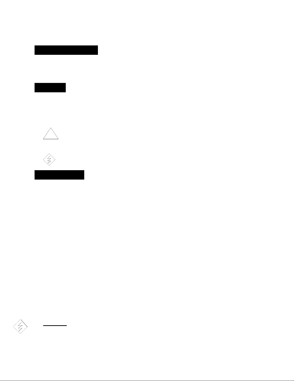
4. Orientation / Mounting
Proper installation and orientation of the FIREBAR® Circulation Heater is important to insure maximum
efficiency and minimum sheath temperatures. The unique shape of this flat element offers many
advantages, but they can only be realized if the heater is properly oriented. Every effort should be made
to position the heater as recommended.
When the FIREBAR® immersion heater is located in a tank the preferred tank orientation is shown in
Figure # 1. The tank should be mounted horizontally with both nozzles out the top. In this position the
"TOP" marking on the heater flange or screw plug should be positioned on top. This ensures that natural
convection can occur within the tank, even though the primary flow may be created by a pump. Also,
heaters with element supports require special attention to insure that they are not positioned to restrict
flow. The element supports create a baffling effect and must be installed so that the nozzles and "TOP"
are both ositioned up.
WATLOW IND.n # 6 INDUSTRIAL LOOP RD. n HANNIBAL MO, 63401n PHONE 573-221-2816 n FAX 573-221-3723
WATLOW IND. FIREBAR
®
Circulation Heater Installation & Maintenance Manual
I&M Number: 316-42-1-1 Page: 3
Date: 06-11-08 Rev: 2.00
________________________________________________________________________________________________________________________________________________________________________________________________________________________
"TOP" stamped
on flange
"TOP" stamped
on flange
OUTLET
INLET
OUTLET
Preferred Orientation
INLET
Optional Orientation
Figure # 1
If the tank is installed in any other position, it's important that "TOP" be located on the same side as the
nozzles. This will insure that element supports create a baffling effect, and that flow can easily move
through the element bundle. Unless fluid velocity is high, side orientation of nozzles and elements
are not recommended.
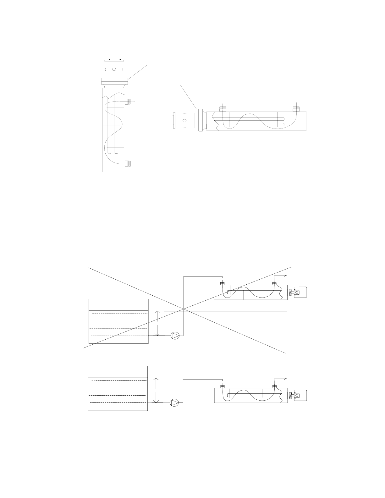
Figure #2 shows the preferred position of the circulation heater when pumping liquif from a tank through
the heater. The NPSH (Net Positive Suction Head) is one of the most important factors when
determining the location of the heater.
NPSH
PUMP
INCORRECT HEATER POSITION - HEATER ABOVE NPSH
NPSH
PUMP
CORRECT HEATER POSITION - HEATER BELOW NPSH
Figure # 2
Furnish adequate space for horizontal or vertical installation. Space should be allowed for immersion
heater removal from tank.
WATLOW IND.n # 6 INDUSTRIAL LOOP RD. n HANNIBAL MO, 63401n PHONE 573-221-2816 n FAX 573-221-3723
 Loading...