

Page 1

Winona, Minnesota USA
ISO 9001
F4T Controller
Installation and Troubleshooting
User’s Guide
TOTAL
CUSTOMER
SATISFACTION
3 Year Warranty
Registered Company
1241 Bundy Boulevard., Winona, Minnesota USA 55987
Phone: +1 (507) 454-5300, Fax: +1 (507) 452-4507
http://www.watlow.com/F4T
1720-6742 Rev. A Made in the U.S.A.
January 2019
Page 2
Safety Information
We use note, caution and warning symbols throughout this document to draw your attention to
important operational and safety information.
A “NOTE” marks a short message to alert you to an important detail.
A “CAUTION” safety alert appears with information that is important for protecting your
equipment and performance. Be especially careful to read and follow all cautions that
apply to your application.
A “WARNING” safety alert appears with information that is important for protecting you,
others and equipment from damage. Pay very close attention to all warnings that apply to
your application.
The safety alert symbol, (an exclamation point in a triangle ç) precedes a general
CAUTION or WARNING statement.
The electrical hazard symbol, (a lightning bolt in a triangleÓ) precedes an electric shock
hazard CAUTION or WARNING safety statement. Further explanations follow:
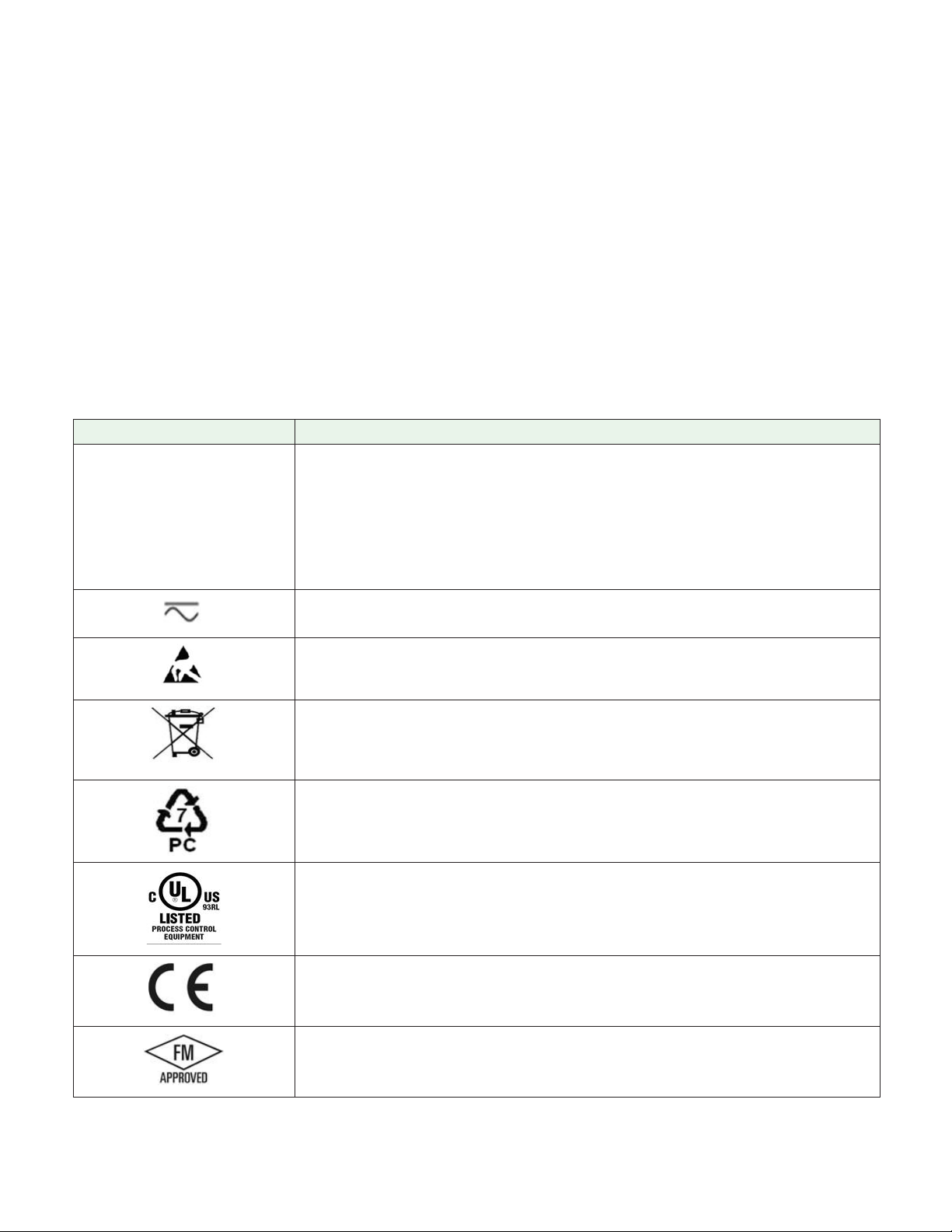
Symbol Explanation
CAUTION: Warning or Electrical Hazard that needs further explanation than label on unit can provide. Consult QSG for further infor-
ç
Ó
mation.
CAUTION
WARNING
Electrical
or
Shock Hazard
AVERTISSEMENT: mise en garde ou danger qui demande plus de
précisions que l’information sur l’étiquette de l’unité. Consultez le
manuel de l’utilisateur pour plus d’informations.
Unit can be powered with either alternating current (ac) voltage or
direct current (dc) voltage.
ESD Sensitive product, use proper grounding and handling techniques when installing or servicing product.
Do not throw in trash, use proper recycling techniques or consult
manufacturer for proper disposal.
Enclosure made of Polycarbonate material. Use proper recycling
techniques or consult manufacturer for proper disposal.
Unit is a Listed device per Underwriters Laboratories®. It has been
evaluated to United States and Canadian requirements for Process
Control Equipment. CSA 22.2#14, File 158031, UL 61010, File
E185611 QUYX, QUYX7. . See: www.ul.com
Unit is compliant with European Union directives. See Declaration
of Conformity for further details on Directives and Standards used
for Compliance.
Unit has been reviewed and approved by Factory Mutual as a
Temperature Limit Device per FM Class 3545 standard. See: www.
fmglobal.com
Page 3

Symbol Explanation
Unit has been reviewed and approved by CSA International for use
as Temperature Indicating-Regulating Equipment per CSA C22.2 No.
24. See: www.csagroup.org
This F4T User’s Guide is copyrighted by Watlow Electric Manufacturing Company, © May 2016
with all rights reserved.
• © 2010-2012, QNX Software Systems Limited. All rights reserved.
• © 2008 -2014, Crank Software Inc. All rights reserved.
• Watlow® and TRU-TUNE® are registered trademarks of Watlow Electric Manufacturing
Company.
• UL® is a registered trademark of Underwriter's Laboratories Incorporated.
• Modbus® is a registered trademark of Schneider Automation Incorporated.
• Vaisala® is a registered trademark of Vaisala OY Corporation.
• Microsoft® and Windows® are registered trademarks of the Microsoft Corporation.
Quencharc® is a registered trademark of ITW Paktron.
10-07433 Rev. –
Page 4

TC
Table of Contents
Chapter 1: Overview .....................................2
Available F4T Literature and Resources ......................... 2
Chapter 2: Install and Wire .................................4
Getting Started Quickly...The Logical Approach ...................4
Dimensions ............................................... 4
Installing the F4T .......................................... 5
Panel Mounting the Base .................................5
Flush Mounting the Base ................................. 6
Electrical Isolation .........................................8
Wiring the F4T Base ........................................8
Power Requirements .......................................9
Flex Module (FM) Characteristics .......................... 9
Flex Module Installation .....................................9
Wiring the Modules ....................................... 10
Communications Connections ............................ 24
Chapter 3: Connecting a PC ...............................25
Using the User Interface (UI) to Change or View Ethernet Settings ... 25
Understanding the Front Panel Navigational Buttons ..........25
Connecting the F4T Base to a PC .............................27
DHCP Connection ..................................... 27
Fixed IP Connection ....................................27
Composer Software ....................................... 28
Starting Composer Software .............................28
Verifying Pluggable Flex Module Installation Using Composer ...28
Chapter 4: Calibration ...................................30
Calibrating the F4T Inputs ..................................30
Required Equipment When Performing Calibration ............... 30
Calibration of Analog Inputs ................................. 31
Using Composer Software to Calibrate Analog Inputs ............. 32
Using the User Interface to Calibrate Analog Inputs ...............32
Chapter 5: Troubleshooting ................................33
Replacing the Battery ......................................39
Chapter 6: Appendix ....................................41
F4T Base Specifications ....................................41
F4T Base Ordering Information ...........................44
Flex Modules and Limit I/O Specifications ...................... 45
Flex Module - Mixed I/O Ordering Information ............... 48
Flex Module - Limit Ordering Information ................... 49
Flex Modules - High Density I/O Specifications ..................49
Flex Module - High Density Ordering Information ............. 53
Flex Module - Communications Ordering Information .........53
How to Reach Us .........................................56
Watlow F4T Install & Troubleshooting • 1 • Table of Contents
Page 5

1
Chapter 1: Overview
Available F4T Literature and Resources
Document Title and Part Number Description
This document looks deeper at the system
F4T Setup and Operation User Guide,
part number: 1680-2414 Rev. A
configuration using Composer™ software and
the F4T function blocks and their connections.
Common product usage is described and illustrated through application examples.
F4T Specification Sheet, part number:
WIN-F4T-1118
Watlow Application Guide
Watlow Support Tools DVD, part
number: 0601-0001-0000
To acquire one or more of these documents navigate to the Watlow website where you will
have a choice to download free copies or purchase printed versions. Click on the link
below to nd your document of choice: http://www.watlow.com/F4T. For the Application
Guide, click here: http://www.watlow.com/common/catalogs/les/appguide.pdf
Describes F4T hardware options, features,
benefits and technical specifications.
Comprehensive guide to understanding thermal
principles, electrical noise, best practises for
wiring industrial controls and much more.
Contains all related user documents, tutorial
videos, application notes and the application
guide described above.
Your Comments are Appreciated
In an effort to continually improve our technical literature and ensuring that we are
providing information that is useful to you, we would very much appreciate your comments
and suggestions. Please send any comments you may have to the following e-mail address:
TechlitComments@watlow.com
Technical Assistance
If you encounter a problem with your Watlow controller, review your conguration
information to verify that your selections are consistent with your application: inputs,
outputs, alarms, limits, etc. If the problem persists, you should rst contact the Original
Equipment Manufacturer (OEM) for assistance. If that is not an option you can also get
assistance directly from Watlow:
• Contact a local representative: see last page
• Email: wintechsupport@watlow.com
• Call: 1-800-4WATLOW (1-800-492-8569) or +1 (507) 494-5656 from 7 a.m. to 5 p.m. Central
Standard Time (CST) (Select options for Controls & Software and Technical Support)
Please have the following information available when calling:
• Complete model number • User’s Guide • All conguration information
Watlow F4T Install & Troubleshooting • 2 • Chapter 1 Overview
Page 6

Warranty
This product is warranted by Watlow for a period of 36 months in accordance with the
terms and conditions set forth on Watlow's website which can be accessed at
www.watlow.com/terms.
Return Material Authorization (RMA)
1. Call Watlow Customer Service, (507) 454-5300, for a Return Material Authorization (RMA)
number before returning any item for repair. If you do not know why the product failed,
contact an Application Engineer or Product Manager. All RMA’s require:
• Ship-to address
• Bill-to address
• Contact name
• Phone number
• Method of return shipment
• Your P.O. number
• Detailed description of the problem
• Any special instructions
• Name and phone number of person returning the product.
2. Prior approval and an RMA number from the Customer Service Department is required
when returning any product. Make sure the RMA number is on the outside of the carton
and on all paperwork returned. Ship on a Freight Prepaid basis.
3. After we receive your return, we will examine it to verify the reason for the product
failure. Unless otherwise agreed to in writing, Watlow's standard warranty provisions,
which can be located at www.watlow.com/terms, will apply to any failed product.
4. In the event that the product is not subject to an applicable warranty, we will quote
repair costs to you and request a purchase order from you prior to proceeding with the
repair work.
5. Watlow reserves the right to charge for no trouble found (NTF) returns.
Document Overview and Purpose
The purpose of this document is to assist the installer in providing necessary information to
mount, wire and power up the F4T controller. This document also provides information to
assist in the process of diagnosing problems which might occur during or after the
installation process.
Watlow F4T Install & Troubleshooting • 3 • Chapter 1 Overview
Page 7
2
Chapter 2: Install and Wire
Getting Started Quickly...The Logical Approach
The steps below outline installation and wiring for the base alone. More detail for each is
provided in the following sections.
1. Using this document for orientation, nd the base part number and note any installed
options as well as input voltage requirements.
2. Mount/install the base in the panel (see instructions below for panel mount or ush
mount options).
3. Ensure that incoming power is off and connect to the base power supply connector (see
section "Wiring the F4T Base").
4. Make note of any I/O module slot dependencies installing each one into an appropriate
base slot (see graphic entitled F4T Slot Dependencies under "Flex Module Installation").
5. Connect the wires from each eld device to the associated I/O module connector (see
section "Wiring the Modules").
6. Insert all wired I/O connectors onto the applicable modules and apply power to the
base.
7. Connect the controller to a computer running Composer™ software using an Ethernet
cable (see section "Connecting the F4T Base to a PC").
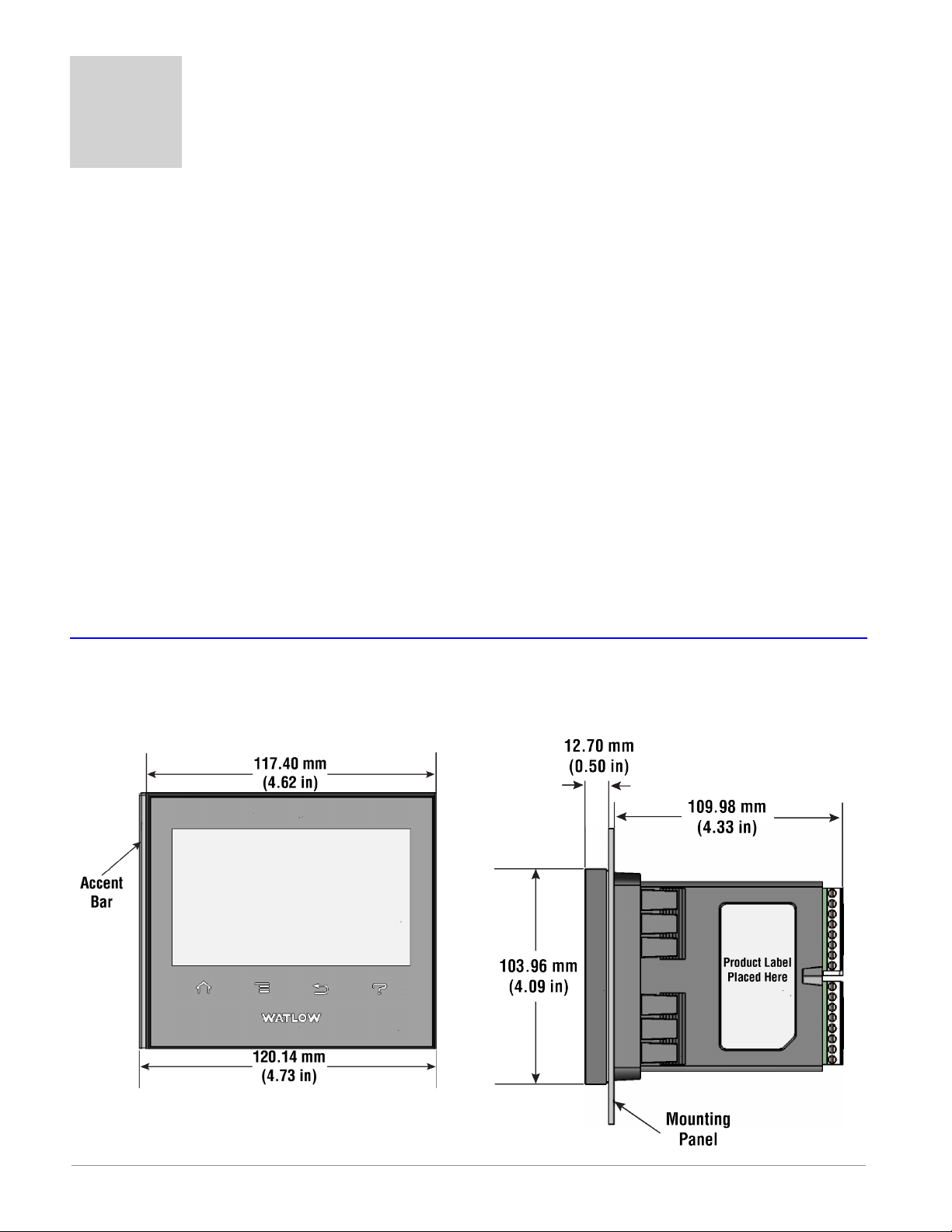
Dimensions
Panel Mount
Front View Side View
Watlow F4T Install & Troubleshooting • 4 • Chapter 2 Install and Wire
Page 8
Dimensions (cont.)
Installing the F4T
Panel Mounting the Base
1. Make the panel cutout using the mounting template dimensions above and insert the
case assembly into the panel cutout.
2. While pressing the case assembly rmly against the panel, slide the Retention Collar
over the back of the controller until the gasket is compressed.
3. For an IP65 seal, alternately place and push
the blade of a screwdriver against each of the
the four corners of the retention collar assembly. Apply pressure to the face of the controller while pushing with the screwdriver. Don't
be afraid to apply enough pressure to properly
install the controller. The seal system is compressed more by mating the retention collar
tighter to the front panel. If you can move the
case assembly back and forth in the cutout, you
do not have a proper seal. The tabs on each side
of the retention collar have teeth that latch into
the ridges on the sides of the controller. Each
tooth is staggered at a different depth from the
front so that only one of the tabs, on each side,
is locked onto the ridges at a time.
Watlow F4T Install & Troubleshooting • 5 • Chapter 2 Install and Wire
Page 9
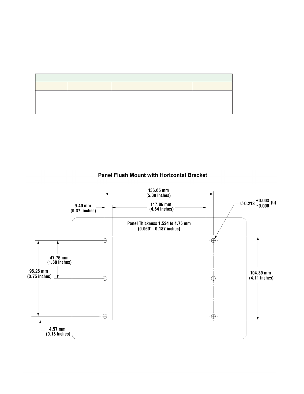
Dimensions (cont.)
Flush Mounting the Base
1. Fabricate the mounting panel per the ush mount vertical or horizontal panel template
(shown below).
2. Press PEM standoffs (based on panel material) into mounting panel per supplier recommendations.
PEM Standoffs
PEM P/N S0-632-6 Z1 S0S-632-6 S0A-632-6 S04-632-6
Material
Steel
(Zinc Plated)
3. Insert the controller through the ush mount bracket and lock it in place with the retention collar.
4. Mount ush mount bracket to back panel with (6) #6-32 screws.
5. Apply overlay to front panel.
Note:
Overlay is provided by the user.
Stainless
Aluminum
Steel
Hardened
Stainless
Steel
Watlow F4T Install & Troubleshooting • 6 • Chapter 2 Install and Wire
Page 10

Dimensions (cont.)
Watlow F4T Install & Troubleshooting • 7 • Chapter 2 Install and Wire
Page 11
Electrical Isolation
Safety Isolation: 2300VÅ (ac)
Controller Power Supply
24 to 28V
24 to 28VÅ (ac)
100 to 240VÅ (ac)
Mechanical Relay,
Solid-State Relay,
NO-ARC Relay
Î (dc)
Safety Isolation
Outputs
Safety Isolation
Safety Isolation
Controller
Low Voltage Power Bus
Low-voltage Isolation: 42V peak
No Isolation
No Isolation
Low-voltage
Isolation
No Isolation
Low-voltage
Isolation
Low-voltage
Isolation
Digital Inputs & Outputs
Switched DC, Open Collector,
Process outputs
Analog Inputs
USB Host
USB Device
Ethernet Port
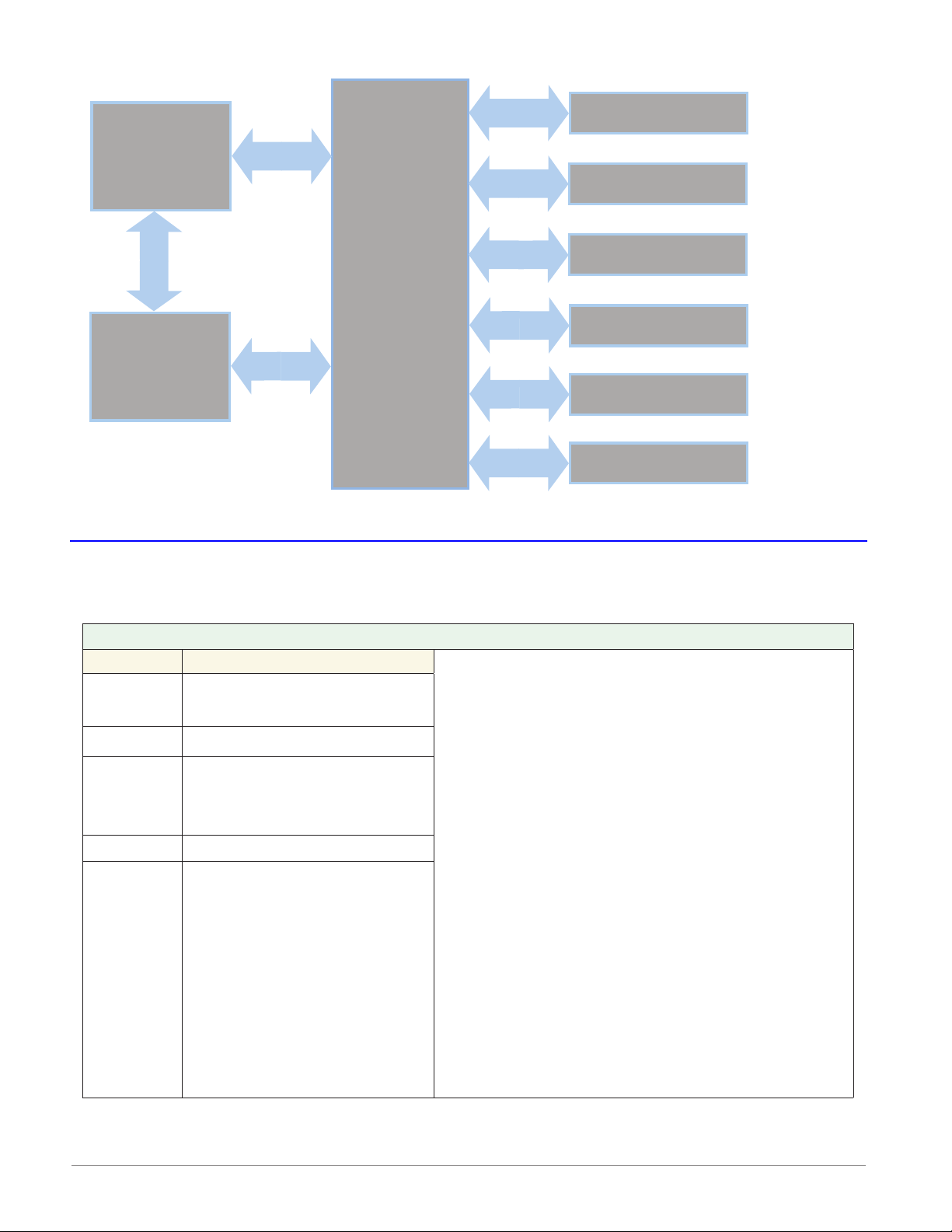
Wiring the F4T Base
Identify Connector Pinout
Terminal Function
98
99
- - - - - - - CX
CY
CZ
- - - - - - - -
GND Functional earth ground
Power input: ac or dc+
Power input: ac or dc-
Inter-module Bus A
Inter-module Bus B
Inter-module Bus Common
Power and Communications
Warning:
Óç
Use National Electric (NEC) or other country-
specic standard wiring and safety practices
when wiring and connecting this controller to
a power source and to electrical sensors or
peripheral devices. Failure to do so may result
in damage to equipment and property, and/or
injury or loss of life.
Avertissement :
Óç
Utilisez les pratiques de câblage et de sécurité de National Electric (NEC) ou les normes
spéciques au pays lors du câblage et de
la connexion de ce régulateur à une source
d'alimentation et aux capteurs électriques ou
aux équipements périphériques. Tout manquement à cette règle pourrait provoquer des
dégâts sur l'équipement et le matériel, et/ou
des blessures personnelles ou des décès.
Watlow F4T Install & Troubleshooting • 8 • Chapter 2 Install and Wire
Page 12
Wire Size and Torque for Screw Terminations
YYN
YY
NY
• 0.0507 to 3.30 mm2 (30 to 12 AWG) single-wire termination or two 1.31 mm2 (16 AWG)
• 0.57 Nm (5.0 lb.-in.) torque
Power Requirements
• 85 to 264VÅ (ac), (Models F4T _ _ [1, 2, 3, 4])
• 20.4 to 30.8VÅ (ac) or Î (dc), (Models F4T _ _ [5, 6, 7, 8])
• 50 to 60 Hz
• Power consumption 23W, 54VA
• Inter-module Bus (CX, CY, CZ)
• Do not route network wires with power wires. Connect
inter-module bus wires in daisy-chain fashion when connecting multiple devices in a network
• The power supply within the controller base meets all
power requirements for any and all inserted modules.
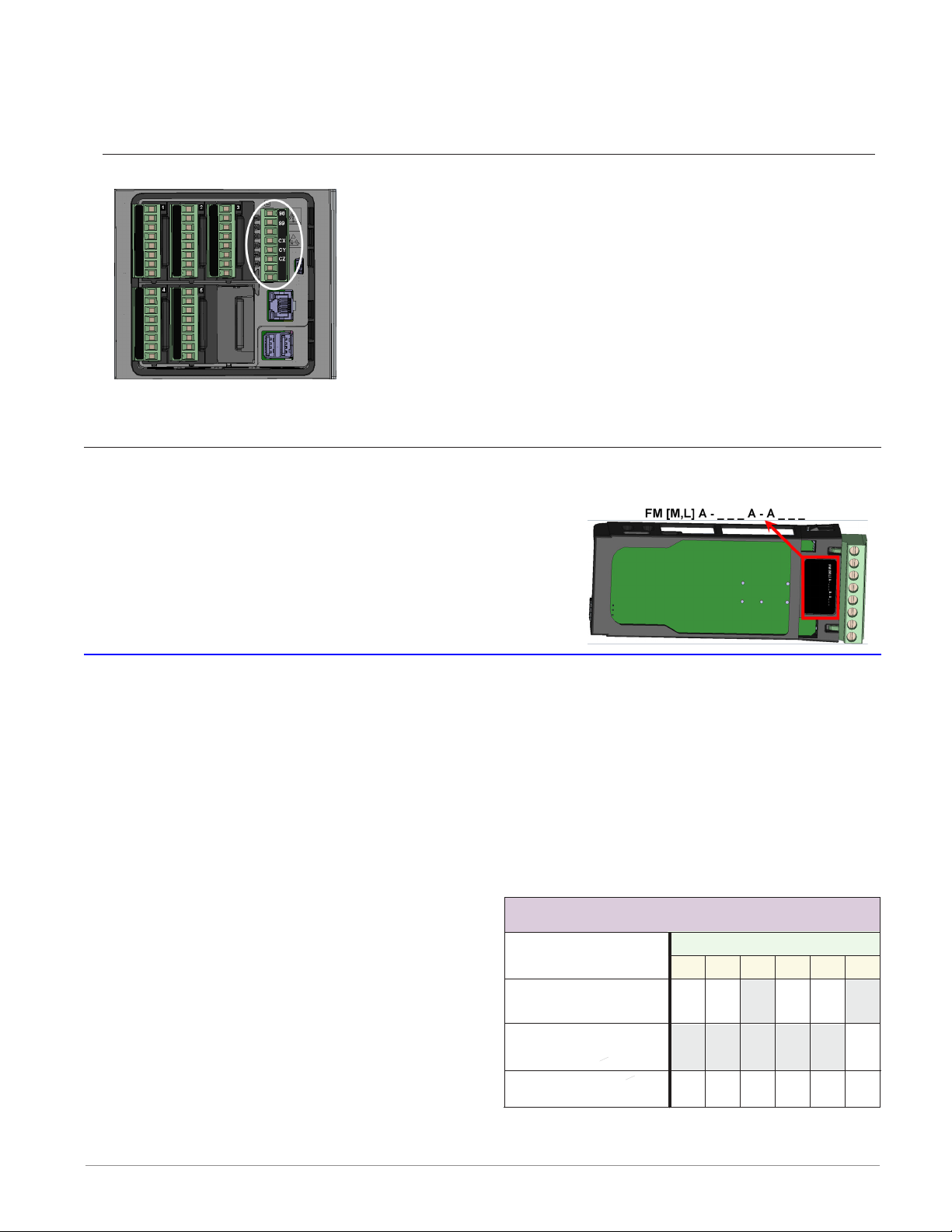
Flex Module (FM) Characteristics
Many of the modules appear to look alike at rst glance, therefore, it is always recommend-
ed that the module part number be noted and veried
prior to plugging it into any of the available slots in a
base. Each module is identied with a part number located on the back side of the assembly right below the connector (black label), as seen in the graphic to the right.
Flex Module Installation - To view video go to www.watlow.com/F4T
Some Flex Modules require that they be installed in specic slots within the base. As an
example, if a communications card is to be installed, it must be placed in slot 6. Slot 6 can
receive and accept any card, however, it is the only slot that allows for a communication
card (see table to the right).
Slots are keyed such that modules cannot be inserted upside down. Insert modules with the
component side facing the right when viewing the controller from the rear.
Installing the modules:
1. Note the part number to determine the
types of inputs and outputs available to be
connected in step 7.
2. Turn off power to the controller.
3. Select a slot for the module (see table to
right). If replacing a module, remove the
old module.
4. Afx corresponding slot number labels
(provided) to the module and to the removable screw terminal block.
Watlow F4T Install & Troubleshooting • 9 • Chapter 2 Install and Wire
Flex Module - Slot Dependencies
Module Type
Dual SSR *
FMHA-K
Communications
FMCA-(2)
All Other Modules
Y = Allowed
* Reguires two adjacent slots
YN
NNNN
YYYY
N = Not allowed
Slot #
Y
456123
Page 13

5. With the component side of the module facing right (viewing the controller from the
rear) insert the module in to the slot until it latches.
6. Remove the screw terminal block from the module.
7. Wire eld devices to the appropriate terminals (see. Wiring details for each input and
output are provided in the following sections.
8. Reconnect the wired screw terminal block to the module. Be sure to reconnect the terminal block to the correct module.
9. Restore power to the controller.
Note:
If a module is swapped out and replaced with a different type or moved to another open
slot after configuration, the controller will no longer function properly without being reconfigured using Composer™ software.
Note:
To minimize the possibility of unwanted downtime due to a module being removed and
installed into the wrong slot, affix the slot number labels (as directed in step 4 above) to
each module (as shown in the graphic below, white circle) and each removable screw terminal block.
Wiring the Modules
Prior to wiring any of the I/O modules described in this document it is recommended that
the warnings and notes listed below be reviewed.
CAUTION:
To prevent damage to the controller, do not connect wires to unused terminals.
AVERTISSEMENT: Pour prévenir tout endommagement du régulateur, ne pas faire de raccor-
dements à des bornes inutilisées.
CAUTION
Switching pilot duty inductive loads (relay coils, solenoids, etc.) with the mechanical relay,
solid-state relay or open collector output options requires the use of an R.C. suppressor for
AC load or a diode for a DC load.
AVERTISSEMENT: les charges inductives de commutation de lampes témoins (bobines de re-
lais, solénoïdes, etc.) avec des options de sortie à relais mécanique, de relais statique ou collecteur ouvert requièrent un dispositif antiparasite R.C.
Watlow F4T Install & Troubleshooting • 10 • Chapter 2 Install and Wire
ç
ç
Quencharc Note:
Page 14
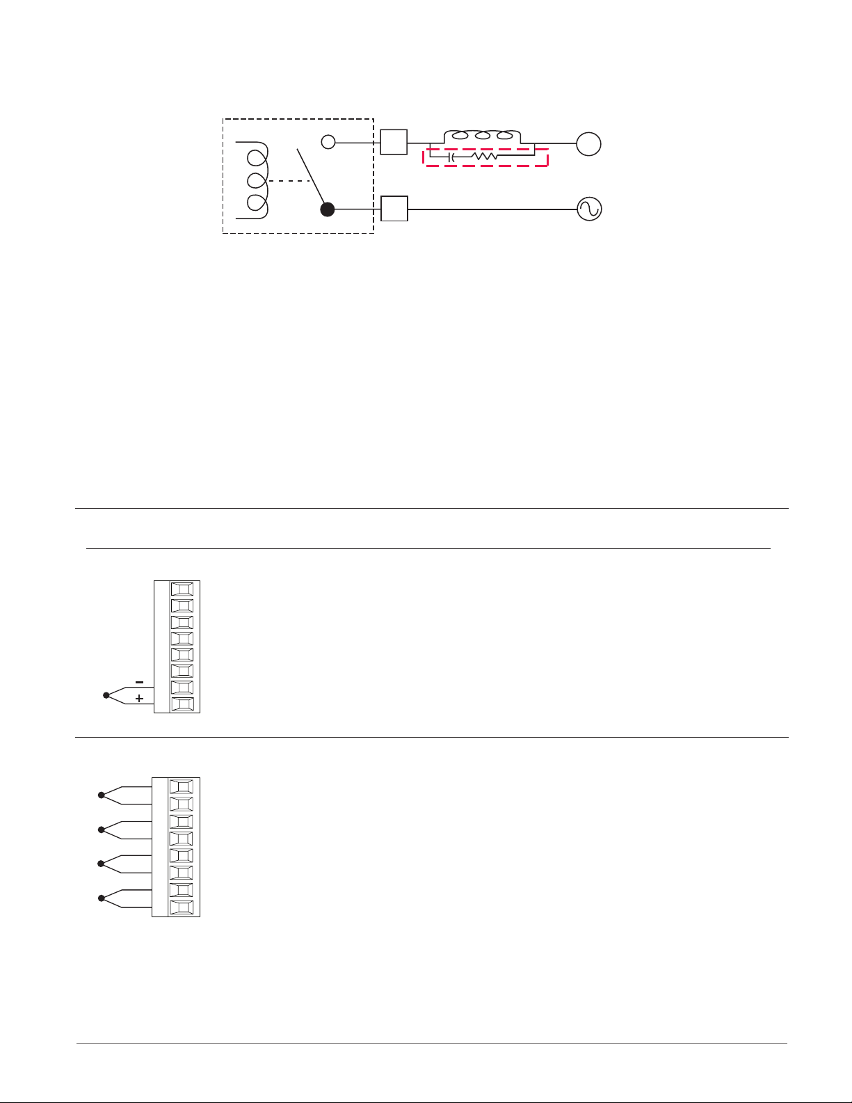
Place the Quencharc directly across the external coil as shown below. For a DC load, place
User Load
the cathode of the diode, to the positive voltage of the load and the anode to the ground of
the load.
_
L
Quencharc
Watlow Part #: 0804-0147-0000
_
K
N
Note:
It is possible that the terminal strip labeling for any given module could be the same. For
example, if a Thermocouple input module is installed in slot 1 and 2, each slot would have
S1 and R1 on its label. When referencing either of these inputs the differentiating factor is
the module slot number, therefore the reference should be input 1 of slot number x.
Note:
Maintain electrical isolation between the analog input, digital input-outputs, switched dc/
open collector outputs and process outputs to prevent ground loops.
Note:
The F4T meets IP10 requirements when the empty slots have slot caps installed.
Note:
Maximum wire size and torque for screw terminations:
• 0.0507 to 3.30 mm2 (30 to 12 AWG) single-wire termination or two 1.31 mm2 (16 AWG)
• 0.57 Nm (5.0 lb.-in.) torque
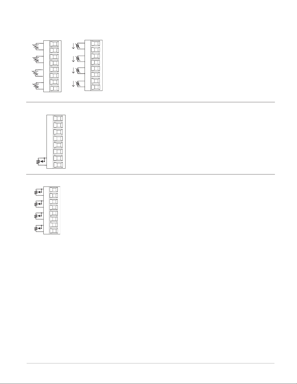
Input Connections
Thermocouple FM [M, L] A - [L, U, Y] _ _ A - A _ _ _
• Grounded or ungrounded sensors, greater than 20MΩ input impedance, 2kΩ source resistance max.
• 3 microampere open-sensor detection
• Thermocouples are polarity sensitive. The negative lead (usually red)
S1
R1
must be connected to S terminal
• To reduce errors, the extension wire for thermocouples must be of the
same alloy as the thermocouple.
Thermocouple (High Density) FMHA - RAAA - A _ _ _
-
S1
+
R1
-
S2
+
R2
-
S3
+
R3
-
S4
+
R4
• Grounded or ungrounded sensors, greater than 20MΩ input impedance, 2kΩ source resistance max
• 3 microampere open-sensor detection
• Thermocouples are polarity sensitive. The negative lead (usually
red) must be connected to S terminal
• To reduce errors, the extension wire for thermocouples must be of
the same alloy as the thermocouple
Watlow F4T Install & Troubleshooting • 11 • Chapter 2 Install and Wire
Page 15
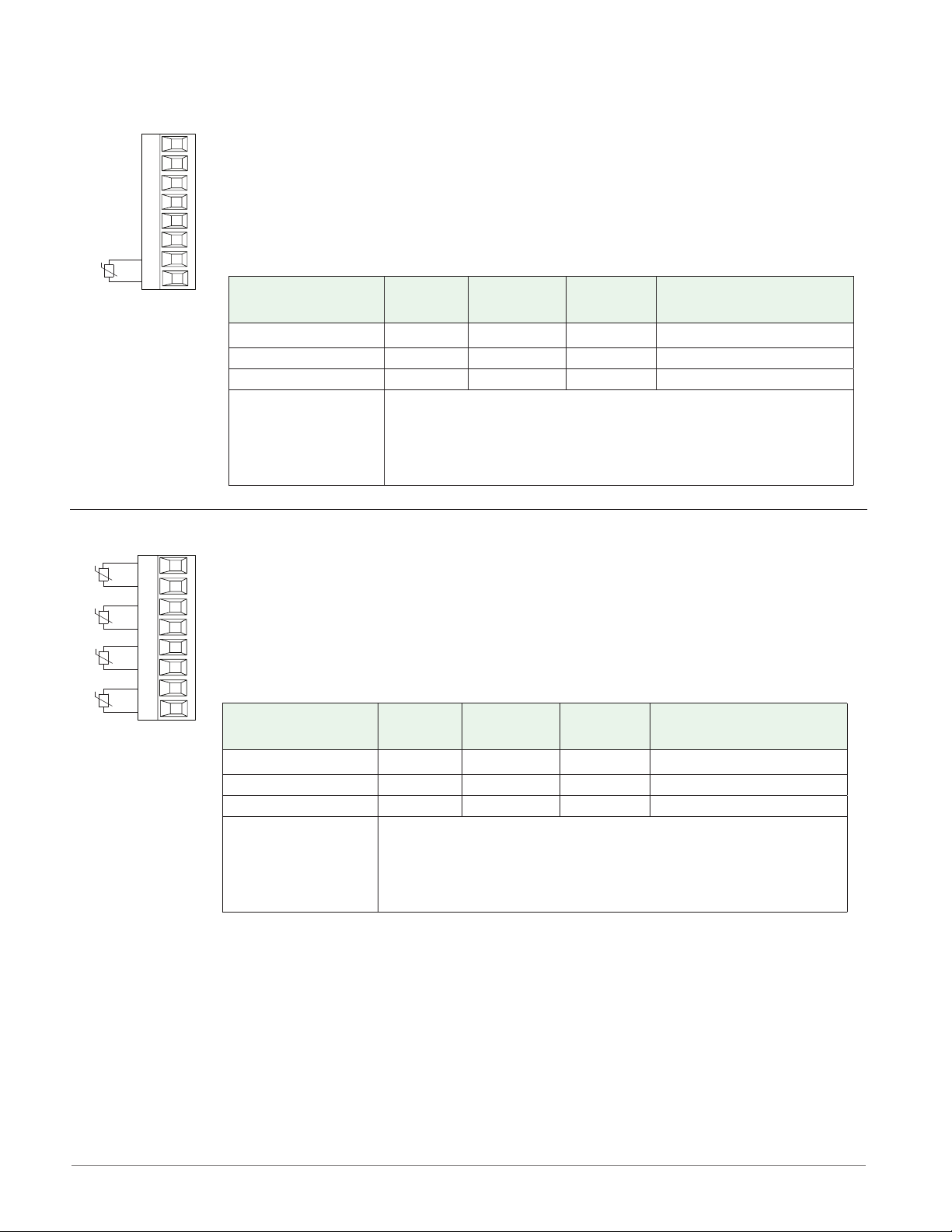
RTD FM [M, L] A - [L, U, Y*] _ _ A - A _ _ _
RTD
RTD
2-wire RTD
• 2 or 3-wire platinum, 100
and 1,000 Ω @ 32°F (0°C)
calibration to DIN curve
(0.00385 Ω/Ω/°C)
T1
S3
S1
R1
S1
2-wire
S2
T1
S3
S1
R1
S1
3-wire
• RTD excitation current
of 0.09 mA typical. Each
ohm of lead resistance
may affect the read-
ing by 2.55°C for a 100
ohm platinum sensor or
0.25°C for a 1000 ohm
sensor.
• For 3-wire RTDs, the S1
lead (usually white) must
be connected to R1.
* This option does not sup-
port 3-wire RTDs
RTD (High Density) FMHA - RAAA - A _ _ _
Lead Wire Resistance
Each wire for 2-Wire
RTDs, not to exceed 10
ohms maximum.
AWG Ohms/1000ft
14 2.575
16 4.094
18 6.510
20 10.35
22 16.46
24 26.17
26 41.62
28 66.17
Note:
3-wire RTD's self-compensate
for lead wire resistance up
to 10 Ω of wire resistance.
S1
R1
S2
R2
S3
R3
S4
R4
• Platinum, 100 and 1,000 Ω @ 32°F
(0°C) calibration to DIN curve
(0.00385 Ω/Ω/°C)
• RTD excitation current of 0.09 mA
typical. Each ohm of lead resistance
may affect the reading by 2.55°C for
a 100 ohm platinum sensor or 0.25°C
for a 1000 ohm sensor (see table to
right)
Process FM [M, L] A - [L, U] _ _ A - A _ _ _
• 0 to 20 mA @ 100 Ω input impedance
• 0 to 10VÎ (dc) @ 20 kΩ input impedance
• 0 to 50 mVÎ (dc) @ 20 MΩ input impedance
+
-
T1
S1
amperes
-
S1
+
R1
volts
• Scalable
Lead Wire Resistance
Each wire for 2-Wire
RTDs, not to exceed 10
ohms maximum.
AWG Ohms/1000ft
14 2.575
16 4.094
18 6.510
20 10.35
22 16.46
24 26.17
26 41.62
28 66.17
Watlow F4T Install & Troubleshooting • 12 • Chapter 2 Install and Wire
Page 16
Input Connections (cont.)
-
-
CW
Process (High Density) FMHA - RAAA - A _ _ _
Volts
S1
+
R1
-
S2
+
R2
-
S3
+
R3
-
S4
+
R4
Potentiometer FM [M, L] A - [L, U] _ _ A - A _ _ _
CW
S_
R_
CCW
Amps
S1
+
R1
-
S2
+
R2
-
S3
+
R3
-
S4
+
R4
• 0 to 20 mA @ 100 Ω input impedance
• 0 to 10VÎ (dc) @ 20 kΩ input impedance
• 0 to 50 mVÎ (dc) @ 20 MΩ input impedance
• Scalable
• Potentiometer: 0 to 1,200Ω
Potentiometer (High Density) FMHA - RAAA - A _ _ _
• Potentiometer: 0 to 1,200Ω
CCW
CW
CCW
CW
CCW
CW
CCW
S_
R_
S_
R_
S_
R_
S_
R_
Watlow F4T Install & Troubleshooting • 13 • Chapter 2 Install and Wire
Page 17
Input Connections (cont.)
Thermistor FM [M, L] A - [M, T] AAA - A _ _ _
• >20 MΩ input impedance
• 0 to 40kΩ, 0 to 20kΩ, 0 to 10kΩ, 0 to 5kΩ
• 2.252kΩ and 10kΩ base at 77°F (25°C)
• Drive current is 109 μA as a constant current source
• User-selectable curves for Alpha Technics, BetaTHERM and YSI
S1
R1
• User-scaling support for Steinhart-Hart coefcients
Thermistor
Curve Setting
Base R
@ 25 ºC
Alpha
Technics
Curve A 2.252K Curve A 2.2K3A 004
Curve B 10K Curve A 10K3A 016
Curve C 10K Curve C 10K4A 006
Use Steinhart-Hart equation coefficients (A, B and
C) from thermistor manufacturer corresponding to
Custom
the terms of the Steinhart-Hart equation:
1 / T = A + Bln(R) + C (ln(R))
Beta
Therm
YSI
3
Thermistor (High Density) FMHA - PAAA - A _ _ _
S1
R1
S2
R2
S3
R3
S4
R4
• >20 MΩ input impedance
• 0 to 40kΩ, 0 to 20kΩ, 0 to 10kΩ, 0 to 5kΩ
• 2.252kΩ and 10kΩ base at 77°F (25°C)
• Drive current is 109 μA as a constant current source
• User-selectable curves for Alpha Technics, BetaTHERM and YSI
• User-scaling support for Steinhart-Hart coefcients
Thermistor
Curve Setting
Base R
@ 25 ºC
Alpha
Technics
Curve A 2.252K Curve A 2.2K3A 004
Curve B 10K Curve A 10K3A 016
Curve C 10K Curve C 10K4A 006
Use Steinhart-Hart equation coefficients (A, B and
C) from thermistor manufacturer corresponding to
Custom
the terms of the Steinhart-Hart equation:
1 / T = A + Bln(R) + C (ln(R))
Beta
Therm
YSI
3
Watlow F4T Install & Troubleshooting • 14 • Chapter 2 Install and Wire
Page 18
Input Connections (cont.)
Int
Digital Input FMLA - YEBA - A _ _ _
• Update rate 10Hz
• Voltage
- Max. input 36V at 3mA
- Input inactive when =<
B2
D2
2V
- Input active when =>
Vdc
3V at 0.25mA
• Dry contact
- Input inactive when =>
500Ω
- Input active when =<
100Ω
- Max. short circuit 13mA
Digital Input (High Density) FMHA - CAAA - A _ _ _
ernal
Common
DC Input
DC Input
DC Input
DC Input
DC Input
DC Input
Supply
B1
D1
D2
D3
D4
D5
D6
Z1
• Voltage
- Max. input 36V at 3mA
- Input inactive when =<
2V
- Input active when => 3V
at 0.25mA
• Dry contact
Vdc
- Input inactive when =>
500Ω
- Input active when =<
100Ω
- Max. short circuit 13mA
Voltage Input
common
B2
D2
Dry Contact
common
B2
D2
Vdc
Voltage Input Dry Contact
common
B1
_
D
_
D
Z1
24 Vdc
Current Transformer FMMA - C _ _ A - A _ _ _
• Input range is 0 to 50 mA (ac).
• Current transformer part number: 16-0246
• 100 Ω input impedance
• Response time: 1 second maximum
T1
S1
Watlow F4T Install & Troubleshooting • 15 • Chapter 2 Install and Wire
• Accuracy +/-1 mA typical
Page 19

Example: Using a Current Transformer
12A
Is = IpT/R = 50mA
k)
L2 L1
Fuse
SSR
3A x 4
ISC = Ip(full scale) = 50mA(R)/T
CSI = Output N
s = Current in secondary of current transformer
I
p = Current in primary of current transformer
I
T = Number of turns through the primary of the transformer
R = Number of turns in the secondary of the current
transformer (Turns ratio, assuming one primary turn)
ISC = Input Scaling (parameter found in Current function block)
CSI = Current Output Source Instance (parameter found in Current function bloc
12A
x 4 = 48A
:
Turns around CT
48mA
CT Secondary Current
CT Primary Current
Turns around CT
Total current
Output N
Controller
CT Input
CT Ratio R = 1000:1
48mA
Watlow F4T Install & Troubleshooting • 16 • Chapter 2 Install and Wire
Page 20

Output Connections
Mechanical Relay Form A FM [M, L]A - _ _ JA - A _ _ _
• 5 A at 240VÅ (ac) or 30VÎ (dc) maximum resistive load
normally open
common
L2
K2
NO-ARC Relay Form A FMMA - _ _ HA - A _ _ _
• 20 mA at 24V minimum inductive
load
• 125 VA pilot duty at 120/240V Å(ac),
25 VA at 24V Å(ac)
• 100,000 cycles at rated load
• Output does not supply power
• For use with ac or dc
• See Quencharc note (page 12)
L2
K2
• 12A at 122°F (50°C), 85 to 264VÅ (ac)
resistive load only (see derating curve)
• 2,000,000 cycle rating for rated load
normally open
common
L2
K2
• 100 mA minimum load
• 2 mA maximum off state leakage
• Do not use on dc loads
• Output does not supply power
• Do not drive another relay or solenoid
with this output type
• See Quencharc note (page 12)
Solid-State Relay Form A FMMA - _ KKA - A _ _ _
normally open
common
L1
K1
• 0.5A at 149°F (65°C) to 1A at 50°F
(10°C), 24 to 264VÅ (ac) maximum resis-
tive load
normally open
common
L2
K2
• 20 VA 120/240VÅ (ac) pilot duty
• Opto-isolated, without contact suppression
• Maximum off state leakage of 105 microamperes
• Output does not supply power
• Do not use on dc loads
• See Quencharc note (page 12)
L2
K2
L_
K_
Watlow F4T Install & Troubleshooting • 17 • Chapter 2 Install and Wire
Page 21

Output Connections (cont.)
Open
Four Mechanical Relays Form A (High Density) FMHA - JAAA - A _ _ _
normally open
common
normally open
common
normally open
common
normally open
common
L1
K1
L2
K2
L3
K3
L4
K4
• 5 A at 240VÅ (ac) or 30VÎ (dc) maximum resistive load
• 20 mA at 24V minimum load
• 125 VA pilot duty @ 120/240VÅ (ac),
25 VA at 24VÅ (ac)
• 100,000 cycles at rated load
• Output does not supply power.
• For use with ac or dc
• See Quencharc note (page 12)
1
L
normally open
1
K
common
2
L
normally open
2
K
common
3
L
normally open
3
K
common
4
L
normally open
4
K
common
Dual Solid-State Relays, Form A (High Density) FMHA - KAAA - A _ _ _
normally open
normally open
common
common
normally open
normally open
common
common
L1
L1
K1
K1
L2
L2
K2
K2
• 10 A at 20 to 264VÅ (ac) maximum resistive load
• 10A per output at 240VÅ (ac), max. 20A
per card at 122°F (50°C)
• Opto-isolated, without contact suppression
• Maximum off state leakage of 105 microamperes
• Output does not supply power
• Do not use on dc loads.
Note:
This module requires 2 slots, therefore it
cannot be placed in slot 3 or 6.
L1
Normally
L1
K1
Common
K1
L2
Normally Open
L2
K2
Common
K2
Watlow F4T Install & Troubleshooting • 18 • Chapter 2 Install and Wire
Page 22

Output Connections (cont.)
Open
Open
Open
Open
Quad 2 Amp SSR Derating Curve
Amps per Each SSR
SSR FM. All outputs on.
Four 2A Solid-State Relays, Form A (High Density) FMHA - LAAA - A _ _ _
normally open
common
normally open
normally open
common
normally open
L1
K1
L2
L3
K3
L4
• 2A at 20 to 264VÅ (ac) maximum resistive
load
• 50 VA 120/240VÅ (ac) pilot duty
• Optical isolation, without contact suppression
• Maximum off state leakage of 105 µA
• Output does not supply power.
• Do not use on dc loads.
• N.O., COM, N.O wiring (shared common)
between each set of outputs.
• See table below for maximum current output.
All Outputs 100% Duty Cycle
2.2
2.0
1.8
1.6
1.4
1.2
Not Used
Not Used
F4T with 2 FMs: 1 quad
input and 1 quad 2A
SSR FM. Outputs 1 and
3 on.
F4T with 2 FMs: 1 quad
input and 1 quad 2A
1
L
Normally
1
K
Common
2
L
Normally
L3
Normally
K3
Common
L4
Normally
1.0
0.8
0.6
0.4
01510520
25 30 35 40
Ambient Temperature (oC)
F4T with 5 FMs: 1 quad
2A SSR.
F4T with 6 FMs: 1 quad
2A SSR.
45 50
Watlow F4T Install & Troubleshooting • 19 • Chapter 2 Install and Wire
Page 23

Output Connections (cont.)
nor
normally closed
+
3 Mechanical Relays, 2 Form C, 1 Form A (High Density) FMHA - BAAA - A _ _ _
• 5A at 24 to 240VÅ (ac) or 30V
normally open
common
mally closed
normally open
normally open
common
normally closed
Mechanical Relay Form C FM [M, L]A - _ E _ A - A _ _ _
L1
K1
J1
L2
L3
K3
J3
Î (dc) maximum resistive load
• 125VA pilot duty 120/240VÅ
(ac) 25 VA at 24VÅ (ac)
• Output does not supply power
• Form A relay shares common
with one Form C relay.
• See Quencharc note (page 12)
L1
normally open
K1
common
J1
normally closed
L2
normally open
L3
normally open
K3
common
J3
normally closed
normally open
common
normally closed
L1
K1
J1
mum resistive load
• Requires a minimum load of 20 mA at
24V
L1
normally open
• 125 VA pilot duty at 120/240VÅ (ac),
• 5 A at 240VÅ (ac) or 30VÎ (dc) maxi-
25 VA at 24VÅ (ac)
• 100,000 cycles at rated load
• Output does not supply power.
K1
common
J1
• For use with ac or dc
• See Quencharc note (page 12)
Universal Process FMMA - _ F _ A - A _ _ _
• 0 to 20 mA ±30μA into 800 Ω maximum
volts or current -
volts +
current +
F1
G1
H1
load with 5μA nominal resolution
• 0 to 10VÎ (dc) ±15mV into 1 kΩ minimum
load with 2.5mV nominal resolution
• Scalable
0 to 10 V
4 to 20 mA
F1
negative
G1
volts +
• Output supplies power
• Cannot use voltage and current outputs
H1
current
at same time
• Output may be used as retransmit or
control
• Temperature stability 100 ppm/°C
Watlow F4T Install & Troubleshooting • 20 • Chapter 2 Install and Wire
Page 24

Output Connections (cont.)
v
current +
dc
common
Tri-Process/Retransmit (High Density) FMHA - FAAA - A _ _ _
volts - / current -
volts + / current +
F1
H1
• 0 to 20 mA into 400Ω maximum load
• 0 to 10VÎ (dc) into 4 kΩ minimum
load
volts - / current -
olts + / current +
volts - / current -
volts + / current +
F2
H2
F3
H3
• Outputs are scalable
• Output supplies power
• Each output can be independently set
for voltage or current
• Output may be used as retransmit or
control
Switched DC / Open Collector FM [M, L] A - _ CCA - A _ _ _
Switched DC
FM [M, L] A - _ [C] [C] A - A _ _ _
dc -
dc +
W2
Y2
• Output 1 and 2, 30 mA dc
maximum supply current not to
exceed 40 mA combined when
both outputs are used
• Short circuit limited to <50 mA
• 22 to 32VÎ (dc) open circuit
voltage
dc (open collector)
X1
W1
Y1
• Use dc- and dc+ to drive external solid-state relay.
• DIN-A-MITE compatible
Note:
Total current of 40 mA not to be
Open Collector (Output 1 only)
exceeded if both outputs are used.
• 100 mA maximum output current sink
• 30VÎ (dc) maximum supply
FM [M, L] A - _ [C] _A - A _ _ _
voltage
• Any switched dc output can use
the common terminal.
• Use an external class 2 or *SELV
power supply to control a dc
load, with the load positive to
the positive of the power supply, the load negative to the
open collector and common to
the power supply negative.
• *Safety Extra Low Voltage
24V
F
0 to 20 mA
0 to 20 mA
0 to 20 mA
0 to 10 V
H
Not Used
F
0 to 10 V
H
Not Used
F
0 to 10 V
H
Switched DC
X_
common
W_
24V
Y_
Open Collector
common
X1
dc -
W1
Y1
negative
1
volts +
or
1
current +
negative
2
volts +
or
2
current +
negative
3
volts +
3
or
dc -
dc +
Power Supply
Load
Watlow F4T Install & Troubleshooting • 21 • Chapter 2 Install and Wire
Page 25

Output Connections (cont.)
open collect
open collect
open collect
open collect
open collect
open collect
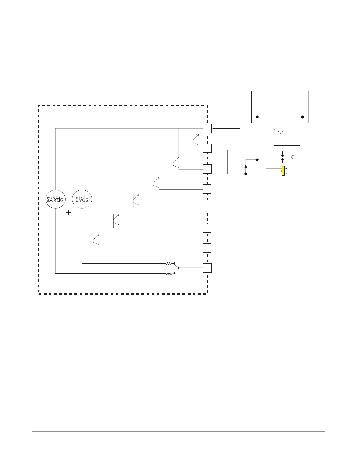
Six Digital Outputs (High Density) FMHA - CAAA - A _ _ _
Common
Internal
or/switched dc
or/switched dc
or/switched dc
or/switched dc
or/switched dc
or/switched dc
Supply
B1
D1
D2
D3
D4
D5
D6
Z1
Open Collector
• Maximum switched voltage is 32VÎ
(dc)
• 400mA, maximum open circuit voltage of 25VÎ (dc), typical 8VÎ (dc)
at 80mA
• Maximum output sink current per
output is 1.5A (external class 2 or
*SELV supply required)
• Total sink current for all outputs not
to exceed 8A
• Do not connect outputs in parallel
• *Safety Extra Low Voltage
Switched DC
• User selectable voltage, 5VÎ (dc) at
130mA or 19 to 22VÎ (dc) at 80mA
Open Collector Outputs
24Vdc
Switched DC Outputs
24Vdc
5Vdc
User Selectable
B1
D1
D2
D3
D4
D5
D6
Z1
B1
D1
D2
D3
D4
D5
D6
Z1
Voltage
Digital Output - Switched DC Wiring Example
B1
D1
24Vdc
5Vdc
D2
D3
D4
D5
Htr 2
Htr 3
Htr 1
+
+
+
-
DC90-60C0-0000
D6
Z1
Internal Supply
User Selectable
Voltage
Note:
As a switched DC output; this output is a constant current output delivering 750 mW, current limited to 150 mA. The internal supply is 5V(dc) open circuit. Pin Z1 is shared to all
digital outputs. This type of output is meant to drive solid state relays, not mechanical
Watlow F4T Install & Troubleshooting • 22 • Chapter 2 Install and Wire
Page 26
Output Connections (cont.)
relays. As an open collector output, use an external power supply with the negative wired
to B1, the positive to the coil of a pilot mechanical relay and the other side of the coil
wired to D_. Each open collector output can sink 1.5 A with the total for all open collector
outputs not exceeding 8 amperes. Ensure that a kickback diode is reverse wired across the
relay coil to prevent damage to the internal transistor.
Digital Output - Open Collector Wiring Example
Power Supply
5 to 32 V(dc)
Open Collector Outputs
Common
B1
D1
D2
-
Fuse
An example fuse is
Bussmann AGC-1 1/2
Diode
+
24Vdc
5Vdc
Internal Circuitry
D3
Relay
D4
D5
D6
Z1
User Selectable
Voltage
Watlow F4T Install & Troubleshooting • 23 • Chapter 2 Install and Wire
Page 27

Communications Connections
Slot B, E
232 (TX)
232 (RD)
EIA-232/485 Modbus RTU Communications
485 T+/R+
485 T-/R-
485 common
485 T+/R+
485 T-/R-
232 common
to DB9 pin 2 (RD)
to DB9 pin 3 (TX)
CB
CA
CC
CB
CA
C5
C3
C2
• Wire T-/R- to the A terminal
of the EIA-485 port.
• Wire T+/R+ to the B terminal
of the EIA-485 port.
• Wire common to the common
terminal of the EIA-485 port.
• Do not route network wires
with power wires. Connect
network wires in daisy-chain
fashion when connecting
multiple devices in a network.
• A termination resistor may be
required. Place a 120 Ω resistor across T+/R+ and T-/R- of
last controller on network.
• Do not wire to both the EIA485 and the EIA-232 pins at
the same time.
• Two EIA-485 terminals of
T/R are provided to assist in
daisy-chain wiring.
• Do not connect more than
one controller on an EIA-232
network.
• Do not connect more than 16
controllers on a Standard Bus
EIA-485 network.
• Maximum number of controllers on a Modbus network is
247.
• Maximum EIA-232 network
length: 15 meters (50 feet)
• Maximum EIA-485 network
length: 1,200 meters (4,000
feet)
• 1/8th unit load on EIA-485
bus.
Modbus-IDA
Terminal
DO A CA or CD T-/R-
D1 B CB or CE T+/R+
common common CC or CF common
Note::
This module must be placed in slot 6.
EIA/TIA-485
Name
Watlow Terminal
Label
Function
Watlow F4T Install & Troubleshooting • 24 • Chapter 2 Install and Wire
Page 28

3
Chapter 3: Connecting a PC
Using the User Interface (UI) to Change or View Ethernet Settings
Understanding the Front Panel Navigational Buttons
When looking at the front panel of the F4T, at the bottom of the display, four push buttons
are displayed as icons shown below. The text in this graphic was placed there for clarity only
and is not present on the front panel.
• Home: regardless of the screen currently in view, when pushed, will always return to
the Home screen which displays the following after personalization:
- Loop name, user designated (Chamber Temp, as shown above).
- Control mode (Auto, as shown above).
- Process Value, input connected to the PV receiver of the loop function block.
- Set Point, which represents the desired value to be maintained by the controller.
- PWR, output power levels for heat and cool if both are congured.
- Output Actions, allows a user to monitor the on/off status of user dened inputs or
outputs.
• Menu: as shown below, will provide access to other settings and functions within the
controller.
• Return: when pushed, this button will take the user back to the previous screen until
the top level of either the home screen or the main menu are reached.
• Help: displays information about the controller such as: part number, software revision
etc...
Note:
Menu buttons can change depending on options ordered (Data Logging) and function blocks
used (Alarm).
Watlow F4T System • 25 • Chapter 3 Connecting to a PC
Page 29

Default Ethernet Parameters and Settings
The bracketed bold settings below represent the defaults as delivered from the factory:
• IP Address Mode: [DHCP], Fixed
- DHCP, Dynamic Host Conguration Protocol, allows for dynamic distribution of network
settings by a DHCP server.
- Fixed, also referred to as a static IP address, is congured manually for a specied network.
• Actual IP Address: [192.168.0.222]
• Actual IP Subnet: [255.255.255.0]
- Subnet, a method used to logically divide and isolate networks.
• Actual IP Gateway: [0.0.0.0]
- Gateway, is a device used on the network to route messages with IP addresses that do not
exist on the local network.
• MAC Address: xx:xx:xx:xx:xx:xx (Will be different and unique for each controller)
- MAC address, is a manufacturer supplied address for the network interface card.
• Display Units: [°F] (Fahrenheit), °C (Celsius)
• Modbus® TCP Enable: [Yes], No
- Modbus is an industrially hardened eld bus protocol used for communications from the
controller to other devices on the network.
• Modbus Word Order: [High], Low
- Modbus allows a user to select the word order of two 16-bit words in oating point values.
• Data Map: [1], 2
- Data Map, the user can switch Modbus registers from the comprehensive listing of F4T
registers to a limited set of the legacy F4 controller registers (1 = F4T, 2 = F4 compatibility).
To change Ethernet parameters:
1. Push the Menu, Settings and Network buttons, in that order.
2. Under "Communications Channels" push Ethernet.
3. Change desired settings.
4. Cycle power to the F4T (changes to IP address will take effect until this step is performed)
Watlow F4T System • 26 • Chapter 3 Connecting to a PC
Page 30
Connecting the F4T Base to a PC
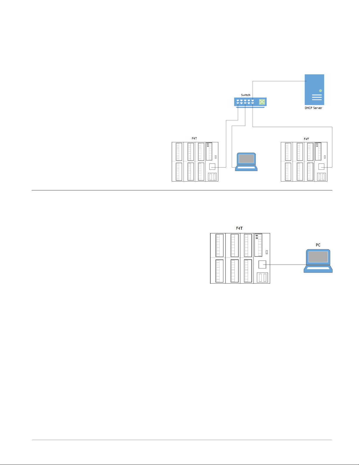
DHCP Connection
There are two ways to connect the F4T over Ethernet to a PC (Fixed IP or DHCP). Because
the F4T is delivered as a DHCP client, we'll take a look at this method rst. The picture
below shows two F4T controllers connected through a switch to a DHCP server. When the
F4Ts are powered up on the network the
DHCP server will assign IP addresses to
them. Using this method allows the F4Ts
to come up in the same network as the PC
with minimal changes to the default F4T
Ethernet conguration.
To connect using DHCP:
1. Connect Ethernet cables from F4T RJ45
connector to the Ethernet switch.
2. Cycle power on the F4T controllers.
3. DHCP server will detect them on the
network and give them IP addresses
automatically.
Fixed IP Connection
If it is desired to connect the F4T directly to a PC as shown in the graphic below follow the
steps below to do so. It should be noted too that there are alternatives to the steps dened
below, this is one way to do this.
To connect using Fixed IP changing PC IP address:
1. Connect Ethernet cables from F4T RJ45 connector
to PC Ethernet port.
2. On the PC navigate to the control panel and click
on Network and Sharing Center
3. Click on Change adapter settings
4. Double-click on the Local Area Connection (the
Ethernet port where cable is connected icon).
5. Click the Properties button.
6. Double-click on Internet Protocol Version 4 (TCP/IPv4) button.
7. Click the radio button identied as Use the following IP address.
8. Change the IP address so that the rst 3 octets match the rst 3 octets of the F4T IP
address while ensuring that the last octet for both the PC and the F4T are unique and
between 0 and 255. If there are other devices on this network all must have a unique address.
9. Change the Subnet mask to match what was entered for the F4T.
10. Click OK when done (this change to the IP address will take effect immediately)
To connect using Fixed IP changing F4T IP address:
1. Push the Menu, Settings and Network buttons, in that order.
2. Under "Communications Channels" push Ethernet.
3. Change desired settings to match the PC ensuring a unique IP address for each.
4. Cycle power to the F4T (changes to IP address will not take effect until this step is pe-
formed).
Watlow F4T System • 27 • Chapter 3 Connecting to a PC
Page 31
Composer Software
Composer™ is the PC-based software used to congure an F4T controller for a specic application. Use Composer to congure which ex modules the controller expects to nd in
each of its slots and to customize the controllers functions for your application. To acquire
Composer software free of charge, point your browser to: http://www.watlow.com/F4T.cfm.
Once there, scroll down to nd and download Composer software.
For detailed instructions in installing and using Composer software see chapter 2 of the F4T
Setup and Operation User Guide.
Starting Composer™ Software
To start the software:
1. Click the Start button and then type composer.exe in the search box to find the executable.
2. Double-click on the file "composer.exe".
Note:
If experiencing difficulties installing or using Composer software, prior to contacting
Watlow technical support, be prepared to send the user log file to the tech support team.
This text file can be found here:
C:\Users\username\AppData\Roaming\Watlow\EZ-Zone Composer\Logs
The red text above will change to the users Windows login name.
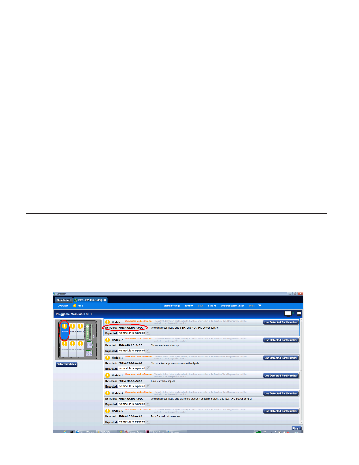
Verifying Pluggable Flex Module Installation Using Composer™
Connect to the desired system:
1. From the systems screen double-click on the online system.
Enter Pluggable Module Screen:
1. Click on the desired Device from the menu bar and then Pluggable Modules.
2. Verify that the detected module (as shown in the graphic below) for each slot matches
what was noted in step 1 (Installing the modules).
Watlow F4T System • 28 • Chapter 3 Connecting to a PC
Page 32

Symbols Related to Pluggable Modules
As viewed from the Menu bar, the symbol that will be displayed to the left of the Pluggable
Modules button will be of the most signicance. The red exclamation will always take precedence.
Symbol Description
The expected module has been detected.
No module has been detected in a slot the controller expects to be empty.
A module has been detected in a slot the controller expects to be empty.
The controller expects a module, but that module is missing or a different
module has been detected.
Watlow F4T System • 29 • Chapter 3 Connecting to a PC
Page 33

4
Chapter 4: Calibration
Calibrating the F4T Inputs
All controllers are calibrated and are accurate to the specied specications (see Appendix
for specications) when they ship from the manufacturing facility.
If an input is suspect as being out of calibration it is recommended that prior to performing any calibration procedure that the user verify that the displayed readings are not within
published specications. Input a known value from a precision source to the analog input and
subtract the displayed value with the known value and compare this difference to the published accuracy range specication (see Appendix for specications) for that type of input.
Use of the Calibration Offset parameter found when viewing the Universal Input parameters
from within Composer™ software or while viewing the input from the front panel Operations
menu, shifts the readings across the entire displayed range by the offset value. Use this parameter to compensate for sensor error or sensor placement error. Typically this value is set
to zero.
Required Equipment When Performing Calibration
Obtain a precision source for millivolts, volts, milliamperes or resistance depending on the
sensor type to be calibrated. Use copper wire only to connect the precision source to the
controller’s input. Keep leads between the precision source and controller as short as possible to minimize error. In addition, a precision volt/ohm meter capable of reading values to 4
decimal places or better is recommended. Prior to calibration, connect this volt/ohm meter
to the precision source to verify accuracy.
Actual input values do NOT have to be exactly the recommended values, but it is critical
that the actual value of the signal connected to the controller be accurately known to at
least four digits.
Watlow F4T Install & Troubleshooting • 30 • Chapter 4 Calibration
Page 34

Calibration of Analog Inputs
To calibrate an analog input, you will need to provide a source of two electrical signals or
resistance values near the extremes of the range that the application is likely to utilize. See
recommended values below:
Sensor Type Precision Source Low Precision Source High
Thermocouple 0.000 mV 50.000 mV
Millivolts 0.000 mV 50.000 mV
Volts 0.000V 10.000V
Milliamps 0.000 mA 20.000 mA
100 Ω RTD 50.00 Ω 350.0 Ω
1,000 Ω RTD 500.0 Ω 3,500 Ω
Thermistor 5 kΩ 50.00 5,000
Thermistor 10 kΩ 150.0 10,000
Thermistor 20 kΩ 1,800 20,000
Thermistor 40 kΩ 1,700 40,000
Potentiometer 0.000 1,200
CAUTION:
Control loops, alarms, limits and any other functions that receive signals from the analog
input will act on the high and low signals applied in this procedure.
Note:
When calibrating a Universal Input configured as a 3-wire RTD, ensure that the calibrated
source is connected across R and both T and S inputs.
Note:
If the user exits this procedure at any point by clicking cancel or simply navigating away
to another screen, the previous calibration for the selected input will be restored.
Note:
The calibration values entered using this procedure will be overwritten whenever the controller has the factory settings restored.
Note:
There are three security settings that can be applied to the calibration screens through
the Diagnostics and Troubleshooting (see the System Overview section of the F4T Setup
and Operation User's Guide for more information) access point:
1. Full Access - full capabilities to calibrate available
2. Read Only - first calibration screen displayed
3. No Access - calibration screens not available
ç
Watlow F4T Install & Troubleshooting • 31 • Chapter 4 Calibration
Page 35

Using Composer™ Software to Calibrate Analog Inputs
To obtain access to the calibration screens:
1. Start Composer software if not already running.
2. From the Dashboard click on Connect to a System and select the appropriate device.
3. From the System Overview screen click on the Device menu button where a drop down
list will appear.
4. Click on Calibrate.
5. Select the appropriate Module and Input and then click on Perform Field Calibration.
6. Follow instructions on the screen.
Using the User Interface to Calibrate Analog Inputs
To calibrate from the F4T front panel:
1. Push the Menu, Service and Calibration buttons, in that order.
2. Select the desired module and input and then push Perform Field Calibration.
3. Follow instructions on the screen.
Note:
At any point in time (using Composer software or the UI) the selected module and input
can be brought back to the factory calibration settings by selecting "Restore Factory Calibration".
Watlow F4T Install & Troubleshooting • 32 • Chapter 4 Calibration
Page 36

5
Chapter 5: Troubleshooting
Indication Description Possible Cause(s) Corrective Action
Alarm won’t
clear or reset
Alarm won’t
occur
Alarm will not clear
or reset with keypad or digital input
Alarm will not activate output
• Alarm latching is active
• Alarm set to incorrect
output
• Alarm is set to incorrect
source
• Sensor input is out of
alarm set point range
• Alarm set point is incorrect
• Alarm is set to incorrect
type
• Digital input function is
incorrect
• Alarm silencing is active
• Alarm blocking is active
• Alarm is set to incorrect
output
• Alarm is set to incorrect
source
• Alarm set point is incorrect
• Alarm is set to incorrect
type
• Reset alarm when process is within range or
disable latching
• Set output to correct
alarm source instance
• Set alarm source to correct input instance
• Correct cause of sensor
input out of alarm range
• Set alarm set point to
correct trip point
• Set alarm to correct
type: process, deviation
or power
• Set digital input function and source instance
• Disable alarm silencing,
if required
• Disable alarm blocking,
if required
• Set output to correct
alarm source instance
• Set alarm source to correct input instance
• Set alarm set point to
correct trip point
• Set alarm to correct
type: process, deviation
or power
Alarm Error Alarm state cannot
be determined due
to lack of sensor
input
Watlow F4T Install & Troubleshooting • 33 • Chapter 5 Troubleshooting
• Sensor improperly wired
or open
• Incorrect setting of sensor type
• Calibration corrupt
• Correct wiring or replace sensor
• Match setting to sensor
used
• Check calibration of
controller
Page 37

Indication Description Possible Cause(s) Corrective Action
Alarm Low Sensor input below
low alarm set point
Alarm High Sensor input above
high alarm set point
Error Input Sensor does not
provide a valid signal to controller
• Temperature is less than
alarm set point
• Alarm is set to latching
and an alarm occurred in
the past
• Incorrect alarm set point
• Incorrect alarm source
• Temperature is greater
than alarm set point
• Alarm is set to latching
and an alarm occurred in
the past
• Incorrect alarm set point
• Incorrect alarm source
• Sensor improperly wired
or open
• Incorrect setting of sensor type
• Calibration corrupt
• Check cause of under
temperature
• Clear latched alarm
• Establish correct alarm
set point
• Set alarm source to
proper setting
• Check cause of over
temperature
• Clear latched alarm
• Establish correct alarm
set point
• Set alarm source to
proper setting
• Correct wiring or replace sensor
• Match setting to sensor
used
• Check calibration of
controller
Limit won’t
clear or reset
Limit will not clear
or reset with keypad or digital input
Limit Error Limit state cannot
be determined due
to lack of sensor
input, limit will trip
Limit Low Sensor input below
low limit set point
• Sensor input is out of
limit set point range
• Limit set point is incorrect
• Digital input function is
incorrect
• Sensor improperly wired
or open
• Incorrect setting of sensor type
• Calibration corrupt
• Temperature is less than
limit set point
• Limit outputs latch and
require reset
• Incorrect alarm set point
• Correct cause of sensor
input out of limit range
• Set limit set point to
correct trip point
• Set digital input function and source instance
• Correct wiring or replace sensor
• Match setting to sensor
used
• Check calibration of
controller
• Check cause of under
temperature
• Clear limit
• Establish correct limit
set point
Watlow F4T Install & Troubleshooting • 34 • Chapter 5 Troubleshooting
Page 38

Indication Description Possible Cause(s) Corrective Action
Limit High Sensor input above
high limit set point
Loop Open
Error
Open Loop Detect
is active and the
process value did
not deviate by a
user-selected value
in a user specied
period with PID
power at 100%.
Loop Reversed
Error
Open Loop Detect is
active and the process value is headed
in the wrong direction when the
output is activated
based on deviation
value and user-selected value.
• Temperature is greater
than limit set point
• Limit outputs latch and
require reset
• Incorrect alarm set point
• Setting of Open Loop
Detect Time incorrect
• Setting of Open Loop Detect Deviation incorrect
• Thermal loop or process
is open
• Open Loop Detect function not required but
activated
• Setting of Open Loop
Detect Time incorrect
• Setting of Open Loop Detect Deviation incorrect
• Output programmed for
incorrect function
• Thermocouple sensor
wired in reverse polarity
• Check cause of over
temperature
• Clear limit
• Establish correct limit
set point
• Set correct Open Loop
Detect Time for application
• Set correct Open Loop
Deviation value for application
• Determine cause of
open thermal loop:
misplaced sensors, load
failure, loss of power to
load, etc.
• Deactivate Open Loop
Detect feature
• Set correct Open Loop
Detect Time for application
• Set correct Open Loop
Deviation value for application
• Set output function correctly
• Wire thermocouple correctly, (red wire is negative)
Ramping Controller is ramp-
ing to new set point
• Ramping feature is activated
• Prole is active
• Disable ramping feature
if not required
• Terminate prole if not
required
Autotuning Controller is
autotuning the control loop
• User started the
autotune function
• Digital input is set to
start autotune
• Wait until autotune
completes or disable
autotune feature
• Connect the digital
input to function other
than autotune, if desired
Watlow F4T Install & Troubleshooting • 35 • Chapter 5 Troubleshooting
Page 39

Indication Description Possible Cause(s) Corrective Action
No heat/cool
action
Output does not
activate load
No Display No display indica-
tion
• Output function is incorrectly set
• Control mode is incorrectly set
• Algorithim is set off
• Output is incorrectly
wired
• Load, power or fuse is
open
• Control set point is incorrect
• Incorrect controller
model for application
• Power to controller is off
• Fuse open
• Breaker tripped
• Safety interlock switch
open
• Separate system limit
control activated
• Wiring error
• Incorrect voltage to controller
• Set output function correctly
• Set control mode appropriately (Open vs Closed
Loop)
• Set heat/cool algorithim
to on/off or PID.
• Correct output wiring
• Correct fault in system
• Set control set point
in appropriate control
mode and check source
of set point: remote,
idle, prole, closed
loop, open loop
• Obtain correct controller model for application
• Turn on power
• Replace fuse
• Reset breaker
• Close interlock switch
• Reset limit
• Correct wiring issue
• Apply correct voltage,
check part number
Watlow F4T Install & Troubleshooting • 36 • Chapter 5 Troubleshooting
Page 40

Indication Description Possible Cause(s) Corrective Action
No Serial
Communication
Cannot establish serial communications
with the controller
• Address parameter incorrect
• Incorrect protocol selected
• Baud rate incorrect
• Parity incorrect
• Wiring error
• EIA-485 converter issue
• Incorrect computer or
PLC communications port
• Incorrect software setup
• Wires routed with power
cables
• Termination resistor may
be required
• Set unique addresses on
network
• Match protocol between
devices
• Match baud rate between devices
• Match parity between
devices
• Correct wiring issue
• Check settings or replace converter
• Set correct communication port
• Correct software setup
to match controller
• Route communications
wires away
from power wires
• Place 120 Ω resistor
across EIA-485 on last
controller
Process
doesn’t control to set
point
Temperature
runway
Process is unstable
or never reaches set
point
Process value continues to increase
or decrease past set
point.
• Controller not tuned correctly
• Control mode is incorrectly set
• Control set point is incorrect
• Controller output incorrectly programmed
• Thermocouple reverse
wired
• Controller output wired
incorrectly
• Short in heater or wiring
• Power controller connection to controller defective
• Controller output defective
• Perform autotune or
manually tune system
• Set control mode appropriately (Open vs Closed
Loop)
• Set control set point
in appropriate control
mode and check source
of set point: remote,
idle, prole, closed
loop, open loop
• Verify output function is
correct (heat or cool)
• Correct sensor wiring
(red wire negative)
• Verify and correct wiring
• Replace heater or repair
wiring
• Replace or repair power
controller
• Replace or repair controller
Watlow F4T Install & Troubleshooting • 37 • Chapter 5 Troubleshooting
Page 41

Indication Description Possible Cause(s) Corrective Action
Heater Error Heater Error • Current through load is
above current trip set
point
• Current through load is
below current trip set
point
Current Error Load current incor-
rect.
• Shorted solid-state or
mechanical relay
• Open solid-state or mechanical relay
• Current transformer load
wire associated to wrong
output
• Defective current transformer or controller
• Noisy electrical lines
• Check that the load current is proper. Correct
cause of over current
and/or ensure current
trip set point is correct.
• Check that the load current is proper. Correct
cause of undercurrent
and/or ensure current
trip set point is correct.
• Replace relay
• Replace relay
• Route load wire through
current transformer
from correct output,
select the output that is
driving the load.
• Replace or repair sensor
or controller
• Route wires appropriately, check for loose
connections, add line
lters
Menus inaccessible
Wrong time
and date
Unable to access
screens or particular parameters of
interest
Real time clock
resets every time
power is lost
• Security set to incorrect
level
• Battery not installed
• Polarity reversed
• Bad battery
• Verify password accuracy
• Login using appropriate
credentials
• Install battery per in-
structions
• Place battery with posi-
tive side of battery facing up in the holder
• Replace battery
Watlow F4T Install & Troubleshooting • 38 • Chapter 5 Troubleshooting
Page 42
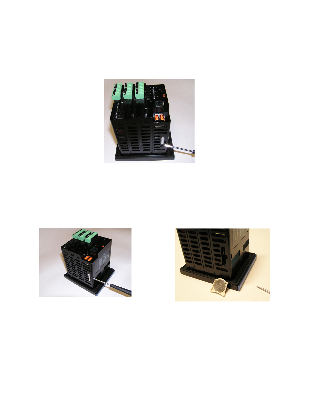
Replacing the Battery
All F4T controllers are equipped with a eld replaceable battery. In a worse case scenario,
the battery should be replaced every 7.5 years. If a replacement is required, the part number for the battery is BR 2032. The Watlow part number for the battery is: 0830-0858-0000
Identifying the battery location:
1. Orient the controller as shown in the picture below.
2. Notice that the battery compartment is located just below the two USB.
Removing the old battery:
1. Ensure all power is off to the F4T.
2. Insert a small screwdriver into the hole provided on the side of the controller as shown
below.
3. Place screwdriver into the bottom of the white battery holder and apply downward
pressure to slide the battery out of the housing. Once removed, make note of the
polarity as seated in the holder.
Watlow F4T Install & Troubleshooting • 39 • Chapter 5 Troubleshooting
Page 43

Installing a new battery:
1. Observing polarity (as shown in the previous graphic), insert the new battery from the
bottom of the holder (2 open slots - red circles as shown in picture below).
2. Insert the battery perpendicular to the plastic housing.
3. Turn and secure the battery so that it sits under the tabs located on the top of the
holder.
4. Insert the holder into the controller housing with the positive side of the battery oriented to the left as shown below.
Note:
If the battery is fully discharged it may be dis-
posed of in normal municipal waste. Because there
will always be some residual metals remaining in
the battery Watlow recommends that this battery
be recycled.
Watlow F4T Install & Troubleshooting • 40 • Chapter 5 Troubleshooting
Page 44

6
Chapter 6: Appendix
F4T Base Specifications
Line Voltage/Power (Minimum/Maximum Ratings)
• High voltage option: 100 to 240V~ (ac) 50/60Hz
• Low voltage option: 24 to 28V (~ ac) (Î dc), 50/60Hz
• Power consumption: 23 W, 54VA maximum
Environment
• NEMA 4X/IP65 - front panel mount conguration only
• 0 to 122°F (-18 to 50°C) operating temperature
• -40 to 185°F (-40 to 85°C) storage temperature
• 0 to 90% RH, non-condensing
Agency Approvals
• UL®/EN 61010 Listed, File E185611 QUYX
• UL® 508 Reviewed
• CSA CC.C#14, File 158031
• FM Class 3545 (congurations with limit modules)
• AMS 2750 E compliant: Analog input process values. Tip: Maximize eld calibration accu-
racy and uniformity by using advanced F4T features such as Calibration Offset and Linearization Function Blocks. Refer to user manual for details.
• RoHS by design, China RoHS Level 2, W.E.E.E.
• CE
• Windows® Hardware Certication
User Interface
• 4.3 inch TFT PCAP color graphic touch screen
• LED backlife >50K hours
• 4 keys: Home, Main Menu, Back, Help
Control Loops
• 1 to 4 PID or ON-OFF control loops
• 0 to 6 Limit loops
• User-selectable action: heat, cool or heat/cool
• Auto-tune with TRU-TUNE+ adaptive control
Control Loops and Over-temperature Limits
• Input sampling: 10Hz
• Output update: 10Hz
Watlow F4T Install & Troubleshooting • 41 • Chapter 6 Appendix
Page 45

Communications
• Ethernet Modbus® TCP
• Isolated communications
Profile Ramp and Soak
• Prole engine affects 1 to 4 loops in sync
• 40 proles with 50 steps per prole
Data Logging
• User selectable parameters: Up to a maximum of 128 active parameters depending on
conguration
• Logging interval: Programmable increments between 0.1 seconds and 60 minutes if
logging to internal memory. Logging directly to USB; 1.0 seconds to 60 minutes
• File types: .CSV for standard data logging or proprietary format for encrypted data log
option
• Storage: 80MB internal memory or to USB memory stick
• File transfer: Internal memory to USB host port or to Ethernet Modbus® TCP
• Transfer options: On demand by user or user programmable based on when a new data log
le record is available. Utilizes TFTP and Samba protocols
• Record: Date and time stamped
Batch Processing with Bar Code Data Entry Via USB Scanner
• Compatible with many bar code types including Code 128, Code 39, Extended Code 39,
Data Matrix, Interleaved 2 of 5, ISSN, SISAC, LOGMARS, QR, UCC/EAN-128
(GS1-128, UPC-A & E)
• Compatible with most USB scanner types such as Zebra DS4308, DS2208, LI2208 and
LS2208
• USB port provides 500mA max. power supply for bar code scanner/base charging
• Display can show bar code elds up to a maximum length of 48 characters.
Characters might wrap to 2 rows after 24 characters
• Part-Prole list entries – approximately 1,000 typical length part numbers of 15 charac-
ters each can be stored. Can easily import different part les via USB thumb drive connection to cover a higher quantity range of part lists
• Program the bar code scanner to add an enter key (carriage return feed) at the end of
each bar code data eld sent to F4T/D4T. Refer to USB scanner user manual.
Trending
• 4 user programmable charts
• 6 pens available per chart
• View analog sensors, process values, set points and power
Watlow F4T Install & Troubleshooting • 42 • Chapter 6 Appendix
Page 46

Number of Function Blocks by Ordering Option
Function Block Basic Set 1 Set 2
Alarm 6 8 14
Compare None 4 16
Counter None 4 16
Linearization 4 4 8
Logic None 12 24
Math None 12 24
Process Value 4 4 8
Special Output
Function
Timer None 6 16
Variable 4 12 24
None 2 4
Real Time Clock with Battery Backup
• Accuracy (typical): +/-3ppm over -15 to 50°C
• Typical battery life: 10 years at 77°F (25°C)
• Field replaceable lithium battery
Compare
• Greater than, less than, equal, not equal, greater than or equal, less than or equal
Counters
• Counts up or down, loads predetermined value on load signal
Linearization
• Interpolated or stepped
Logic
• And, nand, or, nor, equal, not equal, latch, ip-op
Math
• Average, process scale, switch over, deviation scale, differential (subtract), ratio
(divide), add, multiply, absolute difference, minimum, maximum, square root,
sample and hold, pressure-to-altitude and dew point
Process Value
• Sensor backup, average, crossover, wet bulb-dry bulb, switch over, differential
(subtract), ratio (divide), add, multiply, absolute difference, minimum, maximum, square
root, altitude, Vaisala® relative humidity and pressure-to-altitude
Special Output Function
• Compressor control (cool and/or dehumidify with single compressor), motorized valve,
sequencer
Timers
• On pulse, delay, one shot or retentive
Variable
• User value for digital or analog variable
Watlow F4T Install & Troubleshooting • 43 • Chapter 6 Appendix
Page 47
F4T Base Ordering Information
Base includes: Battery Backup, Real-Time Clock, 4.3 inch color graphical touch panel, 2 USB
host, USB conguration port, standard bus, wired Ethernet Modbus® TCP. SCPI protocol and
backwards compatible Modbus® for select key SERIES F4D/P/S parameters (see the F4T Setup
and Operation User's Guide)
Part Number
① ② ③
Base
Type
F4 T AA
③ Base Type
T = Touch Screen
④
Application
Type
⑤
Data
Logging
⑥
Power Supply
Connector &
Voltage, Logo
⑦
Profiles &
Function
Blocks
⑩ ⑪ Documentation, Accent Bar, Replacement
④ Application Type
1 = Standard
X = Custom, contact factory
⑤ Data Logging and Graphic Trend Charts
A = None
B = Graphical trend chart
J = Data logging
K = Data logging with encrypted files
L = Data logging with graphical trend chart
M* = Data logging with encrypted files, graphical trend
*Must also order digit 7: Profiles option D, E or F for batch
processing with bar code data entry feature to be enabled.
charts and batch processing with bar code data
entry.
⑥ Power Supply Connector & Voltage, Logo
Power Supply Connector
1 = 100 to 240Vac Right angle (standard) Ye s
2 = 100 to 240Vac Right angle (standard) No
3 = 100 to 240Vac Front screw Ye s
4 = 100 to 240Vac Front screw No
5 = 24 to 28Vac or Vdc Right angle (standard) Yes
6 = 24 to 28Vac or Vdc Right angle (standard) No
7 = 24 to 28Vac or Vdc Front screw Yes
8 = 24 to 28Vac or Vdc Front screw No
Watlow
Logo
⑦ Profiles and Function Blocks
Profiles Function Blocks
None 40 Profiles
A = X X
B = X X
C = X X
D = X X
E = X X
F = X X
Basic
Set
Set 1 Set 2
1A = Ye s X
1B = Yes
1C = Ye s
1D = Ye s
1E = No X
1F = No
1G = No
1H = No
1J = Replacement connectors only - for the model number
XX = Contact factory, other custom-firmware, preset
d Control Algorithms
1 = 1 0
2 = 2 0
3 = 3 0
4 = 4 0
5 = 0 0
6 = 0 1
7 = 1 1
8 = 2 1
9 = 3 1
A = 0 2
B = 1 2
C = 2 2
Note: Each control loop algorithm will require 1 universal or
Note: Each cascade loop algorithm will require 2 universal or
⑬ ⑭ ⑮ Populated Flex Modules
AAA = No populated flex modules
XXX = Contact factory - Populated flex modules
Note: If AAA is selected you will need to order Flex Modules
⑧ ⑨
Future
Options
Documentation, Accent
Documenta-
tion
DVD/QSG Gray Blue Red
entered
parameters, locked code, logo
thermistor input from a flex module.
thermistor inputs from flex modules.
(FM) next to account for input and output hardware.
⑩ ⑪
Bar, Replacement
Connector & Custom
Connector & Custom
Decorated Brush Aluminium
Control Loop Cascade Loop
d
Control
Algorithms
Accent Bar
X
X
⑬ ⑭ ⑮
Preloaded
Flex
Modules
X
X
None
X
X
Watlow F4T Install & Troubleshooting • 44 • Chapter 6 Appendix
Page 48

Flex Modules and Limit I/O Specifications
1 Universal Input
• Thermocouple, grounded or ungrounded sensors
- >20MΩ input impedance
• Max. of 2KΩ source resistance
• RTD 2 or 3 wire, platinum, 100Ω and 1000Ω @ 32°F (0°C) calibration to DIN curve
(0.00385Ω/Ω/°C)
- Maximum lead resistance 10Ω
• Process, 0-20mA @ 100Ω ,or 0-10V Î(dc) @ 20kΩ input impedance; scalable, 0 - 50mV
Voltage Input Ranges
- Accuracy ±10mV ±1 LSD at standard conditions
- Temperature stability ±100 PPM/°C maximum
Milliamp Input Ranges
- Accuracy ±20µA ±1 LSD at standard conditions
- Temperature stability ±100 PPM/°C maximum
Resolution Input Ranges
- 0 to 10V: 200 µV nominal
- 0 to 20 mA: 0.5 mA nominal
• Potentiometer: 0 to 1,200Ω
• Inverse scaling
Input Type
J ±1.75 0 750 Deg C
K ±2.45 -200 1250 Deg C
T (-200 to 350) ±1.55 -200 350 Deg C
N ±2.25 0 1250 Deg C
E ±2.10 -200 900 Deg C
R ±3.9 0 1450 Deg C
S ±3.9 0 1450 Deg C
B ±2.66 870 1700 Deg C
C ±3.32 0 2315 Deg C
D ±3.32 0 2315 Deg C
F (PTII) ±2.34 0 1343 Deg C
RTD, 100 ohm ±2.00 -200 800 Deg C
RTD, 1000 ohm ±2.00 -200 800 Deg C
mV ±0.05 0 50 mV
Volts ±0.01 0 10 Volts
mAdc ±0.02 2 20 mAmps DC
mAac ±5 -50 50 mAmps AC
Potentiometer,
1K range
Max Error @
25 Deg C
±1 0 1000 Ohms
Accuracy
Range Low
Accuracy
Range High
Units
Watlow F4T Install & Troubleshooting • 45 • Chapter 6 Appendix
Page 49

Operating Range
Input Type Range Low Range High
J -210 °C 1200 °C
K -270 °C 1371 °C
T -270 °C 400 °C
N -270 °C 1300 °C
E -270 °C 1000 °C
R -50 °C 1767 °C
S -50 °C 1767 °C
B -50 °C 1816 °C
C 0 °C 2315 °C
D 0 °C 2315 °C
F (PTII) 0 °C 1343 °C
RTD (100 ohm) -200 °C 800 °C
RTD (1000 ohm) -200 °C 800 °C
mV -50 50
Volts 0 10
mAdc 0 20
mAac -50 50
Potentiometer, 1K
range
0 1200 ohms
Resistance, 5K range 0 5000 ohms
Resistance, 10K range 0 10000 ohms
Resistance, 20K range 0 20000 ohms
Resistance, 40K range
0 40000 ohms
1 Thermistor Input
Input Type
Max Error @
25 Deg C
Thermistor, 5K range ±5 0 5000 Ohms
Thermistor, 10K range ±10 0 10000 Ohms
Thermistor, 20K range ±20 0 20000 Ohms
Thermistor, 40K range ±40 0 40000 Ohms
• 0 to 40KΩ, 0 to 20KΩ, 0 to 10KΩ, 0 to 5KΩ
• 2.252KΩ and 10KΩ base at 77°F (25°C)
• Linearization curves built in
• Third party Thermistor compatibility requirements
Base R @ 25C Alpha Techniques Beta THERM YSI
2.252K Curve A 2.2K3A 004
10K Curve A 10K3A 016
10K Curve C 10K4A 006
Watlow F4T Install & Troubleshooting • 46 • Chapter 6 Appendix
Accuracy
Range Low
Accuracy
Range High
Units
Page 50

1 Temperature Input
• Thermocouple, grounded or ungrounded sensors
- >20MΩ input impedance
• Max. of 2KΩ source resistance
• RTD 2 wire, platinum, 100Ω and 1000Ω @ 32°F (0°C) calibration to DIN curve
(0.00385Ω/Ω/°C)
- Maximum lead resistance 10Ω
1 Digital Input
• Digital input update rate 10Hz
- DC voltage
- Max. input 36V @ 3mA
- Min. high state 3V at 0.25mA
- Max. low state 2V
- Dry contact
- Min. open resistance 10KΩ
- Max. closed resistance 50Ω
- Max. short circuit 13mA
1 Current Transformer Input
• Accepts 0-50mA signal (user programmable range)
• Displayed operating range and resolution can be scaled and are user programmable
• Current input range: 0 to 50mA ac, 100Ω input impedance
• Response time: 1 second max., accuracy ±1mA typical
• Requires optional current transformer, Watlow part number: 16-0246
Switched DC Output
• Switched dc = 22 to 32VÎ (dc) @ 30mA per output, 40mA per pair (option CC)
Open Collector Output
• Switched dc/open collector = 32VÎ (dc) max. @ 100mA max. current sink
Solid-State Relay Output
• Form A, 1A at 50°F (10°C) to 0.5A at 149°F (65°C), 0.5A at 24VÅ (ac) min., 264VÅ (ac)
max., opto-isolated, without contact suppression, 20VA pilot duty at 120/240 VÅ (ac)
Form A Electromechanical Relay Output
• 5A, 24 to 240VÅ (ac) or 30VÎ(dc) max., resistive load, 100,000 cycles at rated load, requires a min. load of 20mA at 24V, 125VA pilot duty at 120/240 VÅ (ac) or 25 VA at 24 VÅ
(ac)
Form C Electromechanical Relay Output
• 5A, 24 to 240VÅ (ac) or 30VÎ(dc) max., resistive load, 100,000 cycles at rated load, requires a min. load of 20mA at 24V, 125VA pilot duty at 120/240 VÅ (ac) or 25 VA at 24 VÅ
(ac)
NO-ARC Relay Output
• Form A, 12A at 122°F (50°C), 85 to 264VÅ (ac), no VÎ(dc), resistive load, 2 million cycles
at rated load
Watlow F4T Install & Troubleshooting • 47 • Chapter 6 Appendix
Page 51

Universal Process/Retransmit Output
• Universal process/retransmit, Output range selectable:
- 0 to 10V Î(dc) into a min. 1,000Ω load
- 0 to 20mA into max. 800Ω load
Resolution
- dc ranges: 2.5mV nominal resolution
- mA ranges: 5 µA nominal resolution
Calibration Accuracy
- dc ranges: ±15 mV
- mA ranges: ±30 µA
Temperature Stability
- 100 ppm/°C
Flex Module - Mixed I/O Ordering Information
Part Number
① ② ③
Module
ID Type
FM M A A A
③ Module Type
M = Mixed I/0
④
Future
Option
Hardware
-
⑤
Input
⑥ ⑦
Output
Hardware
Options
⑧
Future
Option
⑨
Future
Options
⑩
Custom
Options and
Connectors
Custom Options - Firmware,
⑪ d
Overlay, Preset Parameters,
Locked Code
-
⑩ Custom Options and Connectors
A = Right angle screw connector (standard)
F = Front screw connector
⑤ Input Hardware
A = None
U = Universal input - T/C, RTD 2- or 3-wire, 0-10VDC, 0-20mA
T = Thermistor input
C = Current transformer input
⑥ ⑦ Output Hardware Options
Output 1 Output 2
AA = None None
AJ = None Mechanical relay 5A, Form A
AK = None SSR Form A, 0.5A
CA = Switched dc/open collector None
CH = Switched dc/open collector NO-ARC 12A power control
CC = Switched dc/open collector Switched dc
CJ = Switched dc/open collector Mechanical relay 5A, Form A
CK = Switched dc/open collector SSR Form A, 0.5A
EA = Mechanical relay 5A, Form C None
EH = Mechanical relay 5A, Form C NO-ARC 12A power control
EC = Mechanical relay 5A, Form C Switched dc
EJ = Mechanical relay 5A, Form C Mechanical relay 5A, Form A
EK = Mechanical relay 5A, Form C SSR Form A, 0.5A
FA = Universal process/retransmit None
FC = Universal process/retransmit Switched dc
FJ = Universal process/retransmit Mechanical relay 5A, Form A
FK = Universal process/retransmit SSR Form A, 0.5A
KH = SSR Form A, 0.5A NO-ARC 12A power control
KK = SSR Form A, 0.5A SR Form A, 0.5A
Watlow F4T Install & Troubleshooting • 48 • Chapter 6 Appendix
⑪ d Custom Options - Firmware, Overlay,
Preset Parameters, Locked Code
AA = Standard with quick start guide
AB = Standard without quick start guide
AC = Replacement connectors hardware only - for the entered
model number
XX = Custom
Page 52

Flex Module - Limit Ordering Information
Part Number
① ② ③
Module
ID Type
FM L A A A
④
Future
Option
⑤ ⑥ ⑦
Input and
Output
Hardware
-
⑧
Future
Option
③ Module Type
L = Limit
⑤ ⑥ ⑦ Input and Output Hardware
Limit control with
LCJ =
universal input
Limit control with
LEJ =
universal input
Limit control with
LAJ =
universal input
Limit control with
MCJ =
thermistor input
Limit control with
MEJ =
thermistor input
Limit control with
MAJ =
thermistor input
Limit control with
YEB =
temperature input
Functions
Auxiliary
Output
Hardware
Switched dc/
open collector
Mechanical
relay 5A,
Form C
None Mechanical relay
Switched dc/
open collector
Mechanical
relay 5A,
Form C
None Mechanical relay
None Mechanical relay
Limit Output
Hardware
Mechanical relay
5A, Form A
Mechanical relay
5A, Form A
5A, Form A
Mechanical relay
5A, Form A
Mechanical relay
5A, Form A
5A, Form A
5A, Form C
-
⑨
Future
Options
⑩
Custom
Options and
Connectors
Auxiliary
Input
Hardware
None
None
None
None
None
None
Single
digital input
(limit reset)
Custom Options - Firmware,
⑪ d
Overlay, Preset Parameters,
Locked Code
⑩ Custom Options and Connectors
A = Right angle screw connector (standard)
F = Front screw connector
⑪ d Custom Options - Firmware, Overlay,
Preset Parameters, Locked Code
AA = Standard with quick start guide
AB = Standard without quick start guide
AC = Replacement connectors hardware only - for the entered
model number
XX = Custom
Flex Modules - High Density I/O Specifications
4 Universal Inputs
• Thermocouple, grounded or ungrounded sensors
• >20MΩ input impedance
• Max. of 2KΩ source resistance
• RTD 2 or 3 wire, platinum, 100Ω and 1000Ω @ 32°F (0°C) calibration to DIN curve
(0.00385Ω/Ω/°C)
• Process, 0-20mA @ 100Ω ,or 0-10V Î(dc) @ 20kΩ input impedance; scalable, 0 - 50mV
Voltage Input Ranges
- Accuracy ±10mV ±1 LSD at standard conditions
- Temperature stability ±100 PPM/°C maximum
Milliamp Input Ranges
- Accuracy ±20µA ±1 LSD at standard conditions
- Temperature stability ±100 PPM/°C maximum
Resolution Input Ranges
- 0 to 10V: 200 µV nominal
- 0 to 20 mA: 0.5 mA nominal
• Potentiometer: 0 to 1,200Ω
• Inverse scaling
Watlow F4T Install & Troubleshooting • 49 • Chapter 6 Appendix
Page 53

•
Input Type
Max Error @
25 Deg C
Accuracy
Range Low
Accuracy
Range High
Units
J ±1.75 0 750 Deg C
K ±2.45 -200 1250 Deg C
T (-200 to 350) ±1.55 -200 350 Deg C
N ±2.25 0 1250 Deg C
E ±2.10 -200 900 Deg C
R ±3.9 0 1450 Deg C
S ±3.9 0 1450 Deg C
B ±2.66 870 1700 Deg C
C ±3.32 0 2315 Deg C
D ±3.32 0 2315 Deg C
F (PTII) ±2.34 0 1343 Deg C
RTD, 100 ohm ±2.00 -200 800 Deg C
RTD, 1000 ohm ±2.00 -200 800 Deg C
mV ±0.05 0 50 mV
Volts ±0.01 0 10 Volts
mAdc ±0.02 2 20 mAmps DC
mAac ±5 -50 50 mAmps AC
Potentiometer,
1K range
±1 0 1000 Ohms
Operating Range
Input Type Range Low Range High
J -210 °C 1200 °C
K -270 °C 1371 °C
T -270 °C 400 °C
N -270 °C 1300 °C
E -270 °C 1000 °C
R -50 °C 1767 °C
S -50 °C 1767 °C
B -50 °C 1816 °C
C 0 °C 2315 °C
D 0 °C 2315 °C
F (PTII) 0 °C 1343 °C
RTD (100 ohm) -200 °C 800 °C
RTD (1000 ohm) -200 °C 800 °C
mV -50 50
Volts 0 10
Watlow F4T Install & Troubleshooting • 50 • Chapter 6 Appendix
Page 54

Operating Range (cont.)
Input Type Range Low Range High
mAdc 0 20
mAac -50 50
Potentiometer, 1K
range
Resistance, 5K range 0 5000
Resistance, 10K range 0 10000
Resistance, 20K range 0 20000
Resistance, 40K range 0 40000
0 1200
4 Thermistor Inputs
Input Type
Thermistor, 5K range ±5 0 5000 Ohms
Thermistor, 10K range ±10 0 10000 Ohms
Thermistor, 20K range ±20 0 20000 Ohms
Thermistor, 40K range ±40 0 40000 Ohms
• 0 to 40KΩ, 0 to 20KΩ, 0 to 10KΩ, 0 to 5KΩ
• 2.252KΩ and 10KΩ base at 77°F (25°C)
• Linearization curves built in
• Third party Thermistor compatibility requirements
Base R @ 25C Alpha Techniques Beta THERM YSI
2.252K Curve A 2.2K3A 004
10K Curve A 10K3A 016
10K Curve C 10K4A 006
Max Error @
25 Deg C
Accuracy
Range Low
Accuracy
Range High
3 Universal Process/Retransmit Outputs
• Universal process/retransmit, Output range selectable:
- 0 to 10V Î(dc) into a min. 4,000Ω load
- 0 to 20mA into max. 400Ω load
Resolution
- dc ranges: 2.5mV nominal resolution
- mA ranges: 5 µA nominal resolution
Calibration Accuracy
- dc ranges: ±15 mV
- mA ranges: ±30 µA
Temperature Stability
- 100 ppm/°C
Units
3 Mechanical Relay Outputs
• 2 Form C relays, 1 Form A relay. Form A shares common with 1 Form C relay
• Each relay is rated at 5A, 24 to 240VÅ (ac) or 30VÎ (dc)max., resistive load, 100,000
cycles at rated load. Requires a min. load of 20mA at 24V, 125 VA pilot duty at 120/240
VÅ (ac) or 25 VA at 24 VÅ (ac)
Watlow F4T Install & Troubleshooting • 51 • Chapter 6 Appendix
Page 55

4 Mechanical Relay Outputs
Quad 2 Amp SSR Derating Curve
Amps per Each SSR
SSR FM. All outputs on.
• Form A, 5A each, 24 to 240VÅ (ac) or 30VÎ (dc)max., resistive load, 100,000 cycles at
rated load. Requires a min. load of 20mA at 24V, 125 VA pilot duty at 120/240 VÅ (ac) or
25 VA at 24 VÅ (ac)
2 Solid-State Relays
• Form A, 10A max. each SSRs combined at 24VÅ (ac) min., 264VÅ (ac) max., opto-isolated, without contact suppression, max. resistive load 10A per output at 240VÅ (ac), max.
20A per card at 122°F (50°C), max.
4 Solid-State Relays
• Two pairs of SSRs, each pair shares a common
• Form A, 24VÅ (ac) min., 264VÅ (ac) max., opto-isolated, without contact suppression,
resistive load 2A per output at 240VÅ (ac), max. See table for max. current per output
• 50 VA pilot duty at 120/240 VÅ (ac)
All Outputs 100% Duty Cycle
2.2
2.0
1.8
1.6
1.4
1.2
F4T with 2 FMs: 1 quad
input and 1 quad 2A
SSR FM. Outputs 1 and
3 on.
F4T with 2 FMs: 1 quad
input and 1 quad 2A
6 Digital Input/Output Option - (6 DIO)
• Digital input update rate 10Hz
- DC voltage
- Max. input 36V @ 3mA
- Min. high state 3V at 0.25mA
- Max. low state 2V
- Dry contact
- Min. open resistance 10KΩ
- Max. closed resistance 50Ω
- Max. short circuit 13mA
• Digital output update rate 10Hz
1.0
0.8
0.6
0.4
01510520
Ambient Temperature (oC)
25 30 35 40
45 50
F4T with 5 FMs: 1 quad
2A SSR.
F4T with 6 FMs: 1 quad
2A SSR.
- User selectable Switched DC output: 5VÎ (dc) at 130mA or 19 to 22VÎ (dc) at 80mA
- Open Collector output: 32VÎ (dc) at 1.5A maximum, 8A maximum per 6 outputs combined
Watlow F4T Install & Troubleshooting • 52 • Chapter 6 Appendix
Page 56

Flex Module - High Density Ordering Information
Part Number
① ② ③
Module
ID Type
FM H A AAA A
④
Future
Option
Hardware
-
⑤
Input and
Output
⑥ ⑦ ⑧
Future
Option
-
⑨
Future
Options
⑩
Custom
Options and
Connectors
③ Module Type
H = High Density I/O
⑤ Input and Output Hardware
R = 4 universal inputs (T/C, RTD 2-wire, 0-10VDC, 0-20mA)
P = 4 thermistor inputs
C = 6 digital I/O
F = 3 universal process/retransmit outputs
3 mechanical relay 5A, 2 Form C and 1 Form A (Form A
B =
shares a common with one Form C)
J = 4 mechanical relay 5A, Form A
K = 2 SSRs 10A
4 SSRs at 2A each. SSRs grouped in 2 pairs with each pair
L =
sharing a common
Flex Module - Communications Ordering Information
Custom Options - Firmware,
⑪ d
Overlay, Preset Parameters,
Locked Code
Part Number
① ② ③
Module
ID Type
FM C A 2 A A
④
Future
Option
-
⑤
Comm.
Option
⑥ ⑦ ⑧
Future
Option
⑤ Communication Option
2 = Modbus® RTU 232/485*
⑩ Custom Options and Connectors
A = Right angle screw connector (standard)
F = Front screw connector
⑪ d Custom Options - Firmware, Overlay,
Preset Parameters, Locked Code
AA = Standard with quick start guide
AB = Standard without quick start guide
AC = Replacement connectors hardware only - for the
entered model number
XX = Custom
-
⑨
Future
Options
⑩
Custom
Options and
Connectors
Custom Options - Firmware,
⑪ d
Overlay, Preset Parameters,
Locked Code
Watlow F4T Install & Troubleshooting • 53 • Chapter 6 Appendix
Page 57

Declaration of Conformity
–
–
Series F4T
WATLOW Electric Manufacturing Company ISO 9001since 1996.
1241 Bundy Blvd.
Winona, MN 55987 USA
Declares that the following products:
Designation:
Model Numbers: F4T X X (1 to 8)
Classification: Process Controller Base Installation Category II,
Rated Voltage and Frequency: High Voltage 100
Rated Power Consumption: Up to 23 Watts with six modules loaded.
Series F4T ¼ DIN Control
X AA XX X–XXX X = any number or letter.
rated IP65 or IP40 if flush mount option is used.
240 Vac 50/60 Hz, F4TXX(1, 2, 3, 4)
Low Voltage 24 – 28 Vac/dc 50/60 Hz, F4TXX(5, 6, 7, 8)
Only the front display is considered part of the ultimate enclosure, the unit is considered an open type
process control, it requires an ultimate enclosure and at least one Watlow EZ-ZONE
useful function. All Flex Modules were tested as part of F4T system for compliance with the following directives.
®
FM “Flex Module” to have a
2004/108/EC Electromagnetic Compatibility Directive
EN 61326-1
EN 55011
EN 61000-4-2 2009 Electrostatic Discharge Immunity
EN 61000-4-3 2010 Radiated Field Immunity
EN 61000-4-4 2012 Electrical Fast-Transient / Burst Immunity
EN 61000-4-5 2006 Surge Immunity
EN 61000-4-6 2009 Conducted Immunity
EN 61000-4-11 2004 Voltage Dips, Short Interruptions and Voltage Variations Immunity
EN 61000-3-2 2009 Harmonic Current Emissions
EN 61000-3-3
SEMI F47 2000 Specification for Semiconductor Sag Immunity Figure R1-1
1
NOTE: Not for use in Commercial or Residential locations without additional emissions protection.
2
NOTE: To comply with flicker requirements cycle time may need to be up to 160 seconds if load current is at 15A, or the
maximum source impedance needs to be < 0.13
2013
2010
2
2013 Voltage Fluctuations and Flicker
Electrical equipment for measurement, control and laboratory use – EMC
requirements (Industrial Immunity, Group 1 Class A
. Unit power of F4T model complies with 61000-3-3 requirements.
1
Emissions).
2006/95/EC Low-Voltage Directive
EN 61010-1 2010 Safety Requirements of electrical equipment for measurement, control
and laboratory use. Part 1: General requirements
Compliant with 2011/65/EC RoHS2 Directive
Per 2002/96/EC W.E.E.E Directive and 2006-66-EC Battery Directive Please Recycle Properly.
Joe Millanes Winona, Minnesota, USA
Name of Authorized Representative
Director of Operations
Place of Issue
July 2014
Title of Authorized Representative Date of Issue
Signature of Authorized Representative
Watlow F4T Install & Troubleshooting • 54 • Chapter 6 Appendix
Page 58

Declaration of Conformity
Series EZ-ZONE® Flex Modules
WATLOW Electric Manufacturing Company ISO 9001
1241 Bundy Blvd.
Winona, MN 55987 USA
Declares that the following products:
Designation:
Model Numbers:
Series EZ-ZONE
FMLA-(LAJ, LCJ, LEJ, MAJ, MCJ, MEJ, YEB
FMMA-X(A
FMHA-(R
1
FMCA-XAAA-A(A1,F1,B1,G1)XX; Note: X1 = Any letter or number
1,P1,C1,F1,B1
Classification: FMLA, FMMA and FMHA are Process Control modules, FMCA are
Communication modules; Modules are Integrated Controls in either EZ-
®
ZONE
CC or F4T Bases; Modules are IP10 when properly installed.
Rated Voltage and Frequency: Relay, SSR or No-Arc Control outputs 24 - 240 Vac 50/60 Hz,
Switched DC, Process and communications; low voltage SELV
Rated Power Consumption: At max 50°C, see manual for ratings at other ambient temperatures.
No-arc relays 15A 1.C, Dual SSR module 1.C 10A each output,
Mechanical relay 5A 125 VA, 25 VA at 24 Vac 1.B, Discreet SSR 1/2A
1.C 20VA, Quad SSR 1.C 0.7A 50 VA, Hex I/O 1.5A, all others SELV
limited energy.
Flex Modules are considered components and have no function in and of themselves, it is only when installed in a
Watlow EZ-ZONE
®
CC or F4T Base enclosure that they have useful function. Modules were tested as part of these
systems for compliance with the following directives.
2004/108/EC Electromagnetic Compatibility Directive
EN 61326-1 2006 Electrical equipment for measurement, control and laboratory use
– EMC requirements (Industrial Immunity, Class B Emissions).
®
Flex Modules
1,C1
,E,F1,K)(A1,C1,H,J,K)A-A(A1,F1,B1,G1)XX
1
)A-A(A1,F1,B1,G1)XX
,J,K,L1)AAA-A(A1,F1,B1,G1)XX
since 1996.
2006/95/EC Low-Voltage Directive
EN 61010-1:2010 ED3
All FM’s in all bases are
compliant with this standard.
EN 60730-1:2011
EN 60730-2-9:2010
1
Compliant output options.
When in EZ-ZONE
®
CC Base.
Per 2002/96/EC W.E.E.E Directive and 2006-66-EC Battery Directive
See the Declarations of Conformity for Watlow EZ-ZONE
Joe Millanes Winona, Minnesota, USA
Name of Authorized Representative
Director of Operations
Title of Authorized Representative Date of Issue
Signature of Authorized Representative
Safety Requirements of electrical equipment for measurement,
control and laboratory use. Part 1: General requirements
Automatic electrical controls for household and similar use –
Particular requirements for temperature sensing controls.
Only certain output options comply with 60730 spacing and dielectric
requirements, see order information for compatible models.
Compliant with 2011/65/EC RoHS2 Directive
for further details on standards used for compliance.
Place of Issue
July 2014
Please Recycle Properly.
®
CC and F4T models
Watlow F4T Install & Troubleshooting • 55 • Chapter 6 Appendix
Page 59

How to Reach Us
S
Corporate Headquarters
Watlow Electric Manufacturing Company
12001 Lackland Road
St. Louis, MO 63146
Sales: 1-800-WATLOW2
Manufacturing Support: 1-800-4WATLOW
Email: info@watlow.com
Website: www.watlow.com
From outside the USA and Canada:
Tel: +1 (314) 878-4600
Fax: +1 (314) 878-6814
Latin America
Watlow de México S.A. de C.V.
Av. Fundición No. 5
Col. Parques Industriales
Querétaro, Qro. CP-76130
Mexico
Tel: +52 442 217-6235
Fax: +52 442 217-6403
Europe
Watlow Plasmatech GmbH
Brennhoehan - Kellau 156
431 Kuchl
Austria
Tel: +3 0244 20129
Email: austria@watlow.com
Website: www.watlow.com
Watlow France
Tour d'Asnières.
4 Avenue Laurent Cély
92600 Asnières sur Seine
France
Tél: + 33 (0) 1 41 32 79 70
Télécopie: + 33(0)1 47 33 36 57
Email: info@watlow.fr
Website: www.watlow.com
Watlow GmbH
Postfach 11 65, Lauchwasenstr. 1
D-76709 Kronau
Germany
Tel: +49 (0) 7253 9400-0
Fax: +49 (0) 7253 9400-900
Email: info@watlow.de
Website: www.watlow.com
Watlow Italy S.r.l.
Viale Italia 52/54
20094 Corsico Milano
Italy
Tel: +39 024588841
Fax: +39 0245869954
Email: italyinfo@watlow.com
Website: www.watlow.com
Watlow Ibérica, S.L.U.
C/Marte 12, Posterior, Local 9
E-28850 Torrejón de Ardoz
Madrid - Spain
T. +34 91 675 12 92
F. +34 91 648 73 80
Email: info@watlow.es
Website: www.watlow.com
Watlow Ltd.
Roby Close, Linby Ind. Estate
Linby
NG15 8AA Nottingham
United Kingdom
Email: info@watlow.co.uk
Website: www.watlow.com
From outside The United Kingdom:
Tel: +44 (0) 115 964 0777
Fax: +44 (0) 115 964 0071
Asia and Pacific
Watlow Singapore Pte Ltd.
20 Kian Teck Lane, 4th Floor
Singapore 627854
Tel: +65 6773 9488
Fax: +65 6778 0323
Email: info@watlow.com.sg
Website: www.watlow.com.sg
Watlow Electric Manufacturing Company (Shanghai) Co. Ltd.
Greenland International Plaza Room 1306
275-8 East Guoding Road, Yangpu District
Shanghai 200433
China
Local Phone: 4006 Watlow (4006 928569)
International: +86 21 3381 0188
Fax: +86 21 6106 1423
Email: info-cn@watlow.com
Website: www.watlow.cn
Watlow Thermal Solutions India Pvt., Ltd.
401 Aarohan Plaza, 4th Floor
No. 6-3-678/1 Panjagutta
Hyderabad 500082 Telangana
India
Tel: +91-40-666 12700
Email: infoindia@watlow.com
Website: www.watlow.com
ワトロー・ジャパン株式会社
〒101-0047 東京都千代田区内神田1-14-4
四国ビル別館9階
Tel: 03-3518-6630 Fax: 03-3518-6632
Email: infoj@watlow.com Website: www.watlow.co.jp
Watlow Korea Co., Ltd.
#2208, Hyundia KIC Building B, 70 Doosan-ro
Geumcheon-gu, Seoul
Republic of Korea
Tel: +82 (2) 2169-2600 Fax: +82 (2) 2169-2601
Website: www.watlow.co.k
瓦特龍電機股份有限公司
80143 高雄市前金區七賢二路189號 10樓之一
電話: 07-2885168 傳真: 07-2885568
Watlow Electric Taiwan Corporation
10F-1 No.189 Chi-Shen 2nd Road Kaohsiung 80143
Taiwan
Tel: +886-7-2885168 Fax: +886-7-2885568
Email: ryeh@watlow.com
Website: www.watlow.com
Your Authorized Watlow Distributor
Watlow Japan Ltd.
Shikoku Building Annex 9th Floor
1-14-4 Uchikanda, Chiyoda-Ku
Tokyo 101-0047
Japan
Tel: +81-3-3518-6630 Fax: +81-3-3518-6632
Email: infoj@watlow.com Website: www.watlow.co.jp
Watlow F4T Install & Troubleshooting • 56 • Chapter 6 Appendix
TOTAL
CUSTOMER
ATISFACTION
3 Year Warranty
 Loading...