

Page 1
Watlow’s F4T Combines
the Flexibility of a
Modular I/O Controller
with Best-in-Class
Ease of Use
F4T
SPECIFICATION SHEET
1
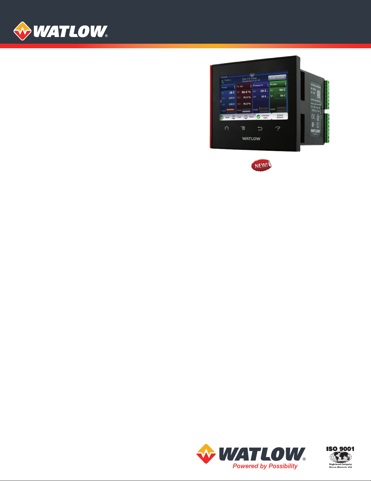
/4 DIN Process Controller
The F4T temperature process controller from Watlow® offers
a wide range of field removable I/O modules for maximum
design flexibility. Configurations can be custom tailored to
meet the scaling needs of a tremendous range of equipment
and applications while providing exactly the hardware
types required for compatibility. The F4T controller also
features a 4.3 inch, color, graphical touch panel. Combining
power, flexibility and functionality, this new controller offers
unmatched versatility, and its best-in-class ease of use could
very well make user manuals a thing of the past.
Features and Benefits
4.3-inch, color touch panel with high-resolution, graphical
user-interface
• Shortens learning curve and reduces operator errors
• Allows channels, profiles, alarms, inputs and outputs to be
personalized with user defined names
Temperature PID, data logger, trend chart,
over/under-temperature limit, power switching,
math, logic, timers and counters combined into an
integrated system
• Lowers ownership costs
• Eliminates the need for separate discrete components
• Reduces complexity
• Simplifies design, ordering and installation
• Saves money
Robust algorithms for temperature, cascade, altitude,
humidity and compressor
• Improves process control
• Offers one to four channels of control
• Provides multiple PID sets
• Enables TRU-TUNE®+ adaptive control algorithm
• Offers 40 ramp and soak profiles with real-time clock and
battery backup
COMPOSER® graphical configuration PC software
• Speeds up and simplifies commissioning
• Archives and documents controller setup
• Connects with controller easily via Ethernet
Email and text alerts
• Notifies users of an event that has occurred such as a
specific profile or step within a profile, alarm condition,
limit condition or analog input error
Batch processing with bar code data entry
• Easily collects and manages data records
• Inputs information from bar code scan for fast and easy
data entry
• Offers foolproof processing via smart profile to part linkage
• Provides data security through password and data log
encrypted file options
• Improves manufacturing robustness via reminder screens
ensuring all data is entered during processing
• Helps ensure compliance with growing regulations and
minimizes warranty exposure
• Eliminates part processing skips or walk arounds due to
improved quality control
• Produces formatted data record report for easy receipt or
record management uses
Many communications options available including Ethernet
Modbus® TCP and SCPI and EIA-232/485 Modbus® RTU
• Offers two USB host ports and one device port
• Simplifies file transfers
• Connects easily
Modular design
• Adapts quickly to evolving requirements
• Offers numerous types of field pluggable modules for
maximum flexibility and easiest compatibility
• Features scalable and modular firmware functions
• Delivers scalable input/output quantities from 1 to 36
SERIES F4S/F4D/F4P backward compatible
• Provides easy retrofit with minimum pain and disruption
• Ensures proper fit in existing SERIES F4 panel cutout
Page 2

Key Features and Options
• 1 to 4 control loops with TRU-TUNE+ adaptive
control algorithm for superior controllability
• 40 profiles for ramp and soak
• Ethernet Modbus® TCP connectivity
• Multiple high-speed USB host ports
• Over/under-temperature limits for safety shutdown
• Universal, thermistor and ac current measurement inputs
• Inputs and outputs expandable from 1 to 36
• SENSOR GUARD prevents unplanned process shutdowns and
product loss by switching to a backup sensor if the primary
sensor fails
• High current outputs for up to 10A heaters or other loads
• Programmable timers, counters, math and logic
• Temperature, cascade, altitude, relative humidity, compressor
algorithms and Vaisala® humidity compensation
• Sequencer start-up and control
• Retransmit and remote set point
• USB configuration port
• Configuration settings can be stored and recalled
• Removable modules and connectors
• Front-panel mount and flush mounting options
• Right angle and front-screw terminal options
• UL® listed, CSA, CE, RoHS, W.E.E.E., FM
• Multi-language options
• English, German, French, Italian, Spanish, Japanese, Korean
and Chinese
• USB wired or wireless mouse user interface
• Use in hazardous location, dirty environments or
applications with gloves
Common Specifications
Line Voltage/Power
• Data retention upon power failure via nonvolatile memory
Functional Operating Range
• Type J: -346 to 2192°F (-210 to 1200°C)
• Type K: -454 to 2500°F (-270 to 1371°C)
• Type T: -454 to 750°F (-270 to 400°C)
• Type E: -454 to 1832°F (-270 to 1000°C)
• Type N: -454 to 2372°F (-270 to 1300°C)
• Type C: 32 to 4200°F (0 to 2315°C)
• Type D: 32 to 4200°F (0 to 2315°C)
• Type F: 32 to 2449°F (0 to 1343°C)
• Type R: -58 to 3214°F (-50 to 1767°C)
• Type S: -58 to 3214°F (-50 to 1767°C)
• Type B: 32 to 3300°F (0 to 1816°C)
• RTD (DIN): -328 to 1472°F (-200 to 800°C)
• Process: -1999 to 9999 units
Calibration Accuracy
• Calibration accuracy and sensor conformity: ±0.1% of
span, ±1°C at the calibrated ambient temperature and
rated line voltage
• Types R, S, B: ±0.2%
• Type T below -50°C: ±0.2%
• Calibration ambient temperature at 77°F ±5°F (25°C ±3°C)
• Accuracy span: 1000°F (540°C) min.
• Temperature stability: Typical ±0.1°F/°F (±0.1°C/°C) rise in
ambient max.
Conguration Diagnostics
• Indicates if modules present match the expected
conguration settings
USB Host Port
• Total of 2 available
• Version: USB 2.0 hi-speed
• Connector: USB Type A, high-retention
• Flash drive must be FAT32 le system
• Max. current 0.5A/port
System Conguration Requirements
• F4T has 6 slots for ex modules (FM)
• EIA-232/485 Modbus® RTU ex module, if used, must occupy
slot 6 location
• A maximum of two 10A SSR FM modules can be used in the F4T
and each will require space for 2 slots. Valid in slots 1, 2, 4 or 5
Wiring Termination—Touch-Safe Terminals
• Right-angle and front-screw terminal blocks for input, output
and power supply connections
• Input, output and power terminals: touch safe, removable,
12 to 30 AWG
F4T Base Specifications
Line Voltage/Power
• High voltage option: 100 to 240VAC +10/-15%, 50/60Hz ±5%
• Low voltage option: 24 to 28VAC/VDC+10/-15%, 50/60Hz ±5%
• Power consumption: 23 W, 54VA
Environment
• NEMA 4X/IP65 front panel mount conguration only
• Operating temperature: 0 to 122°F (-18 to 50°C)
• Storage temperature: -40 to 185°F (-40 to 85°C)
• Relative humidity: 0 to 90%, non-condensing
Agency Approvals
• UL®/EN 61010 Listed, File E185611 QUYX
• UL® 508 Reviewed
• CSA CC.C#14, File 158031
• FM Class 3545 (congurations with limit modules)
• AMS 2750 E compliant: Analog input process values. Tip: Maximize
eld calibration accuracy and uniformity by using advanced F4T
features such as Calibration Oset and Linearization Function
Blocks. Refer to user manual for details.
• RoHS by design, China RoHS Level 2, W.E.E.E.
• CE
• Windows® Hardware Certication
User Interface
• 4.3 inch TFT PCAP color graphic touch screen
• LED backlife >50K hours
• 4 keys: Home, Main Menu, Back, Help
• Multiple languages
• English, German, French, Italian, Spanish, Japanese, Korean
and Chinese
• USB wired or wireless mouse functionality
• Right click for 4 keys: Home, Main Menu, Back, Help
Control Loops
• 1 to 4 PID or ON-OFF control loops
• 0 to 6 Limit loops
• User-selectable action: heat, cool or heat/cool
• Auto-tune with TRU-TUNE+ adaptive control
Control Loops and Over-temperature Limits
• Input sampling: 10Hz
• Output update: 10Hz
Communications
• Ethernet Modbus® TCP
• Isolated communications
Prole Ramp and Soak Option
• Prole engine aects 1 to 4 loops in sync
• 40 proles with 50 steps per prole
Data Logging
• User selectable parameters: Up to a maximum of 128 active
parameters depending on conguration
• Logging interval: Programmable increments between 0.1 seconds
and 60 minutes if logging to internal memory. Logging directly to
USB; 1.0 seconds to 60 minutes
• File types: .CSV for standard data logging or proprietary format for
encrypted data log option
• Storage: 80MB internal memory or to USB memory stick
• File transfer: Internal memory to USB host port or to Ethernet
Modbus® TCP
• Transfer options: On demand by user or user programmable based
on when a new data log le record is available. Utilizes TFTP and
Samba protocols
• Record: Date and time stamped
Page 3
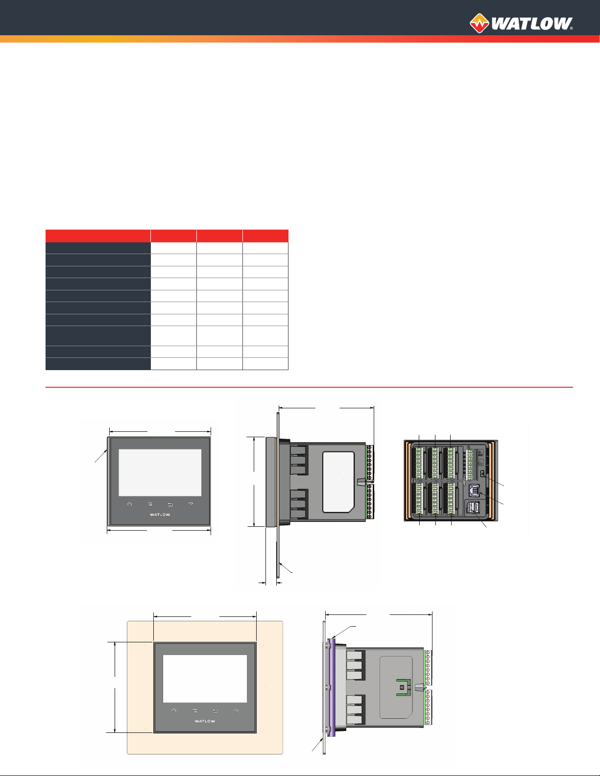
4.09 in.
(103.96 mm)
4.33 in.
(109.98 mm)
(12.7 mm)
Batch Processing with Bar Code Data Entry Via USB Scanner
• Compatible with many bar code types including Code 128,
Code 39, Extended Code 39, Data Matrix, Interleaved 2 of 5, ISSN,
SISAC, LOGMARS, QR, UCC/EAN-128 (GS1-128, UPC-A & E)
• Compatible with most USB scanner types such as Zebra DS4308,
DS2208, LI2208 and LS2208
• USB port provides 500mA max. power supply for bar code
scanner/base charging
• Display can show bar code elds up to a maximum length of
48 characters. Characters might wrap to 2 rows after 24 characters
• Part-Prole list entries – approximately 1,000 typical length part
numbers of 15 characters each can be stored. Can easily import
dierent part les via USB thumb drive connection to cover a
higher quantity range of part lists
• Program the bar code scanner to add an enter key (carriage return
feed) at the end of each bar code data eld sent to F4T/D4T. Refer
to USB scanner user manual.
Number of Function Blocks by Ordering Option
Function Block Basic Set 1 Set 2
Alarm 6 8 14
Compare None 4 16
Counter None 4 16
Linearization 4 4 8
Logic None 12 24
Math None 12 24
Process Value 4 4 8
Special Output Function
(including compressor)
Timer None 6 16
Variable 4 12 24
None 2 4
Trending
• 4 user programmable charts
• 6 pens available per chart
• View analog sensors, process values, set points and power
Real Time Clock with Battery Backup
• Accuracy (typical): +/-3ppm over -15 to 50°C
• Typical battery life: 10 years at 77°F (25°C)
• Field replaceable lithium battery
Compare
• Greater than, less than, equal, not equal, greater than or equal, less
than or equal
Counters
• Counts up or down, loads predetermined value on load signal
Linearization
• Interpolated or stepped
Logic
• And, nand, or, nor, equal, not equal, latch, ip-op
Math
• Average, process scale, switch over, deviation scale,
dierential (subtract), ratio (divide), add, multiply, absolute
dierence, minimum, maximum, square root, sample and hold,
pressure-to-altitude and dew point
Process Value
• Sensor backup, average, crossover, wet bulb-dry bulb, switch over,
dierential (subtract), ratio (divide), add, multiply, absolute
dierence, minimum, maximum, square root, altitude, Vaisala®
relative humidity and pressure-to-altitude
Special Output Function
• Compressor control (cool and/or dehumidify with single
compressor), motorized valve, sequencer
Timers
• On pulse, delay, one shot or retentive
Variable
• User value for digital or analog variable
Panel Mount Dimensions
4.62 in.
(117.4 mm)
Accent
Bar
4.73 in.
(120.14 mm)
Flush Mount Dimensions
4.09 in.
(103.96 mm)
4.62 in.
(117.4 mm)
4.09 in.
(103.96 mm)
0.50 in.
4.33 in.
(109.98 mm)
Slot 1
Slot 2 Slot 3
Slot 4
Slot 5 Slot 6
Mounting Panel
4.81 in.
(122.1 mm)
Flushmount Bracket
USB Type A
(Quantity 2)
USB Mini B
Ethernet
Mounting
Panel
Page 4

F4T Base Ordering Information
Base includes: 4.3 inch color graphical touch panel, 2 USB hosts, USB configuration port, standard bus, Ethernet Modbus® TCP.
SCPI protocol and backwards compatible Modbus® for select key SERIES F4D/P/S parameters.
Part Number
① ②
F4
③
Base
Type
T
④
Application
Type
⑤
Data
Logging
⑥
Power Supply
Connector &
Voltage, Logo
⑦
Profiles &
Function
Blocks
⑧ ⑨
Future
Options
A A
⑩ ⑪
Documentation, Accent
Bar, Replacement
Connector & Custom
⑫
Control
Algorithms
⑬ ⑭ ⑮
Populated
Flex Modules
③
T = Touch screen
④
1 = Standard
X = Custom options, contact factory
⑤
A = None
B =
Graphical trend chart
J =
Data logging
K =
Data logging with encrypted les
L =
Data logging with graphical trend chart
Data logging with encrypted les, graphical trend charts
M =
and batch processing with bar code data entry.
①
Must also order digit 7: Profiles option D, E or F for batch
processing with bar code data entry feature to be enabled.
⑥
1 =
100 to 240VAC Right angle (standard) Yes
2 =
100 to 240VAC Right angle (standard) No
3 =
100 to 240VAC Front screw Yes
4 =
100 to 240VAC Front screw No
5 =
24 to 28VAC or VDC Right angle (standard) Yes
6 =
24 to 28VAC or VDC Right angle (standard) No
7 =
24 to 28VAC or VDC Front screw Yes
8 =
24 to 28VAC or VDC Front screw No
⑦
A =
B =
C =
D =
E =
F =
Note: Refer to top of page 3 “Number of Function Blocks by
Ordering Option”
in each set.
⑧ ⑨
AA =
Future Options
Data Logging and Graphic Trend Charts
Power Supply Connector & Voltage, Logo
Power Supply
Proles Function Blocks
40 Profiles, Battery
None
X X
X X
X X
Backup and
Real-Time Clock
for quantities and types of functions blocks
Base Type
Application Type
Power Supply
Connector
Profiles & Function Blocks
Basic
Set
X X
X X
X X
Future Options
Set 1 Set 2
①
Watlow
Logo
⑩ ⑪
1A =
1B =
1C =
1D =
1E =
1F =
1G =
1H =
1J =
XX =
⑫
1 =
2 =
3 =
4 =
5 =
6 =
7 =
8 =
9 =
A =
B =
C =
Note: Each control loop algorithm requires 1 universal or thermistor
input from a flex module.
Note: Each cascade loop algorithm requires 2 universal or thermistor
inputs from flex modules.
⑬ ⑭ ⑮
AAA =
XXX =
Note: If AAA is selected you will need to order Flex Modules (FM)
next to account for input and output hardware.
Documentation, Accent Bar, Replacement
Documentation
DVD / QSG
Yes X
Yes X
Yes X
Yes X
No X
No X
No X
No X
Replacement connectors only - for the model number
entered
Contact factory, other custom-firmware, preset parameters,
locked code, logo
Control Loop Cascade Loop
No populated flex modules
Contact factory - Populated flex modules
Connector & Custom
Decorated Brush Aluminum
Accent Bar
Gray Blue Red None
Control Algorithms
1 0
2 0
3 0
4 0
0 0
0 1
1 1
2 1
3 1
0 2
1 2
2 2
Populated Flex Modules
Page 5

Flex Modules—High Density I/O Specifications
0 5 10
15
20
25
30
35
40
45
50
Four Universal Inputs (Control Loops, Auxiliary Input)
• Thermocouple: grounded or ungrounded sensors, greater than
20MΩ input impedance, 2kΩ source resistance max.
• RTD: 2-wire, platinum, 100Ω and 1000Ω at 32°F (0°C) calibration to
DIN curve (0.00385Ω/Ω/°C)
• Process: 0-20mA at 100Ω, or 0-10VDC, 0-50mVDC at 20kΩ input
impedance; scalable
• Potentiometer: 0 to 1,200Ω
• Inverse scaling
Four Thermistor Inputs (Control Loops, Auxiliary Input)
• 0 to 40kΩ, 0 to 20kΩ, 0 to 10kΩ, 0 to 5kΩ
• 2.252kΩ and 10kΩ base at 77°F (25°C)
• Preprogrammed Steinhart-Hart coecients for Alpha Techniques
(A curve 2.252k and 10k, C curve 10k), BetaTHERM (2.2K3A, 10K3A
and 10K4A) and YSI (004, 016 and 006)
• User-settable Steinhart-Hart coecients for other thermistors
Three Universal Process/Retransmit Outputs
• Output range selectable
• 0 to 10VDC ±15mV into a min. 4,000Ω load with 2.5mV nominal
resolution
• 0 to 20mA ±30μA into max. 400Ω load with 5μA nominal resolution
• Temperature stability 100ppm/°C
Three Mechanical Relays
• 2 Form C relays, 1 Form A relay. Form A relay shares common with
1 Form C relay
• Each relay is 5A, 24 to 240VAC or 30VDC max., resistive load,
100,000 cycles at rated load. Requires a min. load
of 20mA at 24V, 125VA pilot duty 120/240VAC, 25VA at 24VAC
Four Mechanical Relays
• Form A, 5A ea., 24 to 240VAC or 30VDC max., resistive load, 100,000
cycles at rated load. Requires a min. load of 20mA at 24V, 125VA
pilot duty
Two Solid State Relays
• Form A, 10A max. each SSRs combined at 24VAC min.,
264VAC max., opto-isolated, without contact suppression,
max. resistive load 10A per output at 240VAC, max. 20A per
card at 122°F (50°C), max.
Four Solid State Relays
• Two pairs of SSRs, each pair shares a common
• Form A, 24VAC min., 264VAC max., opto-isolated, without contact
suppression, resistive load 2A per output at 240VAC, max. See table
for max. current per output
Quad 2A SSR Card Derating Curves
2.2
2
1.8
1.6
1.4
1.2
1
Amps Current for each SSR
0.8
0.6
0.4
Ambient Temperature
°C
F4T with 2 ex modules,
1 quad input module and
1 quad 2A SSR module.
Only outputs 1 and 3 ON.
F4T with 2 ex modules,
1 quad input module and
1 quad 2A SSR module. All
4 SSR’s output ON.
F4T with 5 ex modules,
slot below quad 2A SSR
left vacant.
F4T with 6 ex modules,
1 quad 2A SSR card.
Six Digital I/O
• Each independently congurable as input or output
• Dry contact input: update rate 10Hz, min. open resistance 10kΩ,
max. closed resistance 50Ω, max. short circuit 13mA
• DC voltage input: update rate 10Hz, max. input 36V at 3mA, min.
high state 3V at 0.25mA, max. low state 2V
• Switched dc output: max. 5VDC at 130mA, or 19-22VDC at 80mA;
eld selectable
• Open collector output: 32VDC at 1.5A max., 8A max. per 6 outputs
combined
F4T Flex Module—High Density I/O Ordering Information
Part Number
① ②
FM
③
Module ID
Type
H
④
Future
Option
A
③
H = High Density I/O
④
A = Future Option
⑤
R =
4 universal inputs (T/C, RTD 2-wire, 0-10VDC, 0-20mA)
P =
4 thermistor inputs
C =
6 digital I/O
F =
3 universal process/retransmit outputs
3 mechanical relay 5A, 2 Form C and 1 Form A (Form A
B =
Input and Output Hardware
shares a common with one Form C)
J =
4 mechanical relay 5A, Form A
K =
2 SSRs 10A
4 SSRs at 2A each. SSRs grouped in 2 pairs with each pair
L =
①
sharing a common
①
Notes: Input and Output hardware option K: 2 SSR’s 10A.
The 2 SSR’s 10A FM module requires 2 F4T slots. Valid slot locations
are 1, 2, 4 or 5.
The F4T can support a maximum of two total of the K option FM
module types (4 total SSR, 10A).
⑤
⑥ ⑦ ⑧
Input and
Output
Hardware
– –
Future
Options
AAA
Module ID Type
Future Option
⑨
Future
Option
A
⑩
Custom
Options and
Connectors
Firmware, Overlay, Preset
Parameters, Locked Code
⑥ ⑦ ⑧
AAA = Future Options
⑨
A = Future Option
⑩
A =
Right angle screw connector (standard)
F =
Front screw connector
⑪ ⑫
AA =
Standard with quick start guide
AB =
Standard without quick start guide
Replacement connectors hardware only - for the entered
AC =
model number
XX =
Custom
⑪ ⑫
Custom Options-
Future Options
Future Option
Custom Options and Connectors
Custom Options - Firmware, Overlay, Preset
Parameters, Locked Code
Page 6

Flex Modules—Mixed and Limit I/O Specifications
Universal Input
• Thermocouple: grounded or ungrounded sensors, greater than
20MΩ input impedance, 2kΩ source resistance max.
• RTD: 2- or 3-wire, platinum, 100Ω and 1000Ω at 32°F (0°C)
calibration to DIN curve (0.00385Ω/Ω/°C)
• Process: 0-20mA at 100Ω, or 0-10VDC, 0-50mVDC at 20kΩ input
impedance; scalable
• Potentiometer: 0 to 1,200Ω
• Inverse scaling
Thermistor Input
• 0 to 40kΩ, 0 to 20kΩ, 0 to 10kΩ, 0 to 5kΩ
• 2.252kΩ and 10kΩ base at 77°F (25°C)
• Preprogrammed Steinhart-Hart coecients for Alpha Techniques
(A curve 2.252k and 10k, C curve 10k), BetaTHERM (2.2K3A, 10K3A
and 10K4A) and YSI (004, 016 and 006)
• User-settable Steinhart-Hart coecients for other thermistors
Temperature Input
• Thermocouple: grounded or ungrounded sensors, greater than
20MΩ input impedance, 2kΩ source resistance max.
• RTD: 2-wire, platinum, 100Ω and 1000Ω at 32°F (0°C) calibration
to DIN curve (0.00385Ω/Ω/°C)
Digital Input
• Update rate: 10Hz
• DC voltage: max. input 36V at 3mA, min. high state 3V at 0.25mA,
max. low state 2V
• Dry contact input: min. open resistance 10kΩ, max. closed
resistance 50Ω, max. short circuit 13mA
Current Transformer Input
• Accepts 0-50mA signal (user programmable range)
• Displayed operating range and resolution can be scaled and are
user programmable
• Current input range: 0 to 50mA ac, 100Ω input impedance
• Response time: 1 second max., accuracy ±1mA typical
• Use with current transformer (Watlow part number:
16-0246)
Switched DC Output
• Max. 32VDC open circuit
• Max. current 30mA per single output
• Max. current 40mA per pair
Open Collector Output
• Max. 30VDC at 100mA
Solid State Relay (SSR) Output
• Form A, 1A at 50°F (10°C) to 0.5A at 149°F (65°C), 0.5A at 24VAC min.,
264VAC max., opto-isolated, without contact suppression
Form A Electromechanical Relay Output
• 5A, 24 to 240VAC or 30VDC max., resistive load, 100,000 cycles at
rated load, requires a min. load of 20mA at 24V, 125VA pilot duty
Form C Electromechanical Relay Output
• 5A, 24 to 240VAC or 30VDC max., resistive load, 100,000 cycles at
rated load, requires a min. load of 20mA at 24V, 125VA pilot duty
NO-ARC Relay Output
• Form A, 12A at 122°F (50°C), 85 to 264VAC, no VDC, resistive load,
2 million cycles at rated load
Universal Process/Retransmit Output
• Range selectable
• 0 to 10VDC ±15mV into a min. 1,000Ω load with 2.5mV nominal
resolution
• 0 to 20mA ±30μA into max. 800Ω load with 5μA nominal resolution
• Temperature stability 100ppm/°C
Page 7

F4T Flex Module—Mixed I/O Ordering Information
Part Number
① ②
③
④
⑤
⑥ ⑦
⑧
⑨
Output
Future
Option
A
–
Future
Option
A
FM
③
Module ID
Type
M
Future
Option
A
Input
Hardware
–
Module ID Type
Hardware
Options
M = Mixed I/O
④
Future Option
A = Future Option
⑤
A =
None
U =
Universal input - T/C, RTD 2- or 3-wire, 0-10VDC, 0-20mA
T =
Thermistor input
C* =
*
Outputs 1 & 2: FA, FC, FJ and FK.
Current transformer input
Note: If option C is ordered than the following options are NOT valid for
⑥ ⑦
Input Hardware
Output Hardware Options
Output 1 Output 2
AA =
None
AJ =
None Mechanical relay 5A, Form A
AK =
None SSR Form A, 0.5A
CA =
Switched dc/open collector None
CH =
Switched dc/open collector NO-ARC 12A power control
CC =
Switched dc/open collector Switched dc
CJ =
Switched dc/open collector Mechanical relay 5A, Form A
CK =
Switched dc/open collector SSR Form A, 0.5A
EA =
Mechanical relay 5A, Form C None
EH =
Mechanical relay 5A, Form C NO-ARC 12A power control
EC =
Mechanical relay 5A, Form C Switched dc
EJ =
Mechanical relay 5A, Form C Mechanical relay 5A, Form A
EK =
Mechanical relay 5A, Form C SSR Form A, 0.5A
FA =
Universal process/retransmit None
FC =
Universal process/retransmit Switched dc
FJ =
Universal process/retransmit Mechanical relay 5A, Form A
FK =
Universal process/retransmit SSR Form A, 0.5A
KH =
SSR Form A, 0.5A NO-ARC 12A power control
KK =
SSR Form A, 0.5A SSR Form A, 0.5A
None
F4T Flex Module—Limit Ordering Information
Part Number
① ②
③
④
⑤ ⑥ ⑦
Input and
Output Hardware
Options
–
Module ID Type
FM
③
Module ID
Type
L
Future
Option
A
L = Limit
④
Future Option
A = Future Option
⑤⑥⑦
Limit control
with universal
LCJ =
input
Limit control
with universal
LEJ=
input
Limit control
with universal
LAJ =
input
Limit control
YEB =
with thermistor
input
Limit control
with thermistor
input
Limit control
with thermistor
input
Limit control
with temperature input
MCJ =
MEJ =
MAJ =
Notes: Universal input = T/C, RTD 2- or 3-wire, 0-10VDC, 0-20mA
Temperature input = T/C and RTD 2-wire only
Input and Output Hardware Options
Functions
Auxiliary Output
Hardware
Switched dc/
open collector
Mechanical
relay 5A,
Form C
None Mechanical
Switched dc/
open collector
Mechanical
relay 5A,
Form C
None Mechanical
None Mechanical
Limit Output
Mechanical
relay 5A,
Form A
Mechanical
relay 5A,
Form A
relay 5A,
Form A
Mechanical
relay 5A,
Form A
Mechanical
relay 5A,
Form A
relay 5A,
Form A
relay 5A,
Form C
Hardware
⑧
Future
Option
A
⑨
Future
Option
A
–
Auxiliary Input
Hardware
None
None
None
None
None
None
Single digital
input (limit
reset)
Custom
Options and
Connectors
⑩
Custom
Options and
Connectors
⑧
A = Future Option
⑨
A = Future Option
⑩
A =
Right angle screw connector (standard)
F =
Front screw connector
⑪ ⑫
AA =
AB =
AC =
XX =
Custom Options - Firmware, Overlay, Preset
Standard with quick start guide
Standard without quick start guide
Replacement connectors hardware only - for the entered
model number
Custom
⑩
Custom Options-
Firmware, Overlay, Preset
Parameters, Locked Code
⑧
A = Future Option
⑨
A = Future Option
⑩
A =
Right angle screw connector (standard)
F =
Front screw connector
⑪ ⑫
AA =
AB =
AC =
XX =
Custom Options - Firmware, Overlay, Preset
Standard with quick start guide
Standard without quick start guide
Replacement connectors hardware only - for the entered
model number
Custom
⑪ ⑫
Custom Options-
Firmware, Overlay, Preset
Parameters, Locked Code
Future Option
Future Option
Custom Options and Connectors
Parameters, Locked Code
⑪ ⑫
Future Option
Future Option
Custom Options and Connectors
Parameters, Locked Code
Page 8

F4T Flex Modules—Communication Ordering Information
Part Number
① ②
FM
③
C = Communications
④
A = Future Option
⑤
2 =
Notes: EIA-232/485 Modbus® RTU flex module, if used, must occupy
F4T slot 6 location.
⑥ ⑦ ⑧
AAA = Future Options
③
Module ID
Type
C
Modbus® RTU 232/485
④
Future
Option
A
–
Communications Option
Comm.
Option
Module ID Type
Future Option
Future Options
⑤
⑥ ⑦ ⑧
Future
Options
2
AAA
–
⑨
Future
Option
A
⑩
Custom
Options and
Connectors
Custom Options-
Firmware, Overlay, Preset
Parameters, Locked Code
⑨
A = Future Option
⑩
A =
Right angle screw connector (standard)
F =
Front screw connector
⑪ ⑫
AA =
Standard with quick start guide
AB =
Standard without quick start guide
Replacement connectors hardware only - for the entered
AC =
model number
XX =
Custom
⑪ ⑫
Future Option
Custom Options and Connectors
Custom Options - Firmware, Overlay, Preset
Parameters, Locked Code
Accessories
Part Number Description
0830-0870-0000 Protective screen cover (2 per pack)
1
F4T
0822-0705-0000
0216-1285-0000 Flush mount - mounting adapter plate
0847-0400-0000 USB 2.0 to RJ45 Ethernet adapter
0238-1245-ALUM Accent bar (brushed aluminum gray)
0238-1245-REDD Accent bar (brushed aluminum red)
0238-1245-BLUE Accent bar (brushed aluminum blue)
16-0246 Current transformer
0804-0147-0000 RC suppression - Quencharc®
0601-0001-0000 Controller support tools (DVD)
0830-0808-0001
(CAPUSB-MB5)
0830-0808-0002
(CAPUSB-A)
0830-0858-0000 Replacement battery
0822-0769-0000
/4 DIN mounting collar - thru front
panel mount
Rubber plug USB mini
Rubber plug USB host
Module slot plug (for vacant F4T slots
without ex modules
Recommended Third-Party Components
Mfg.
Amphenol USBF 21N SCC
Amphenol
Amphenol RJF 21N SCC
Molex 847290006
Molex 84700-0003 Dust cover www.alliedelec.com
Mfg. Part
Number Description Website
USB - A receptacle
USBBF 21N SCC
with self closing
cap
USB - B receptacle
with self closing
cap
RJ45 receptacle
with self closing
cap
USB type A panel
mount with 2 m
cord
www.alliedelec.com
www.alliedelec.com
www.alliedelec.com
www.alliedelec.com
Documentation
Part Number Description
1720-6742
1680-2414 Setup and Operations User Guide
1440-3329 F4T Controller Quick Start Guide
0600-0095-0000
0600-0096-0000
0600-0097-0000 Mixed I/O Flex Modules Quick Start Guide
Installation and Troubleshooting
User Guide
Communications Flex Modules Quick
Start Guide
High Density Flex Modules Quick
Start Guide
Watlow®, TRU-TUNE®, and COMPOSER® are registered trademarks of Watlow Electric
Manufacturing Company.
UL® is a registered trademark of Underwriter’s Laboratories Incorporated.
Modbus® is a registered trademark of Schneider Automation Incorporated.
Vaisala® is a registered trademark of Vaisala OY Corporation.
Microsoft® and Windows® are registered trademarks of the Microsoft Corporation.
Quencharc® is a registered trademark of ITW Paktron.
Powered by Possibility
To be automatically connected to the nearest
North American Technical Sales Oce:
1-800-WATLOW2 • www.watlow.com
©2020 Watlow Electric Manufacturing Company all rights reserved.
International Technical Sales Offices:
Austria +43 6244 20129 0
China +86 21 3532 8532
France +33 1 41 32 79 70
Germany +49 7253 9400 0
India +91 40 6661 2700
Italy +39 02 458 8841
Japan +81 3 3518 6630
Korea +82 2 2169 2600
Mexico +52 442 256 2200
Singapore +65 6773 9488
Spain +34 91 675 1292
Taiwan +886 7 288 5168
UK +44 115 964 0777
WIN-F4T-0120
 Loading...