

Page 1
ISO 9001
F4T Controller
Setup and Operations
User’s Guide
TOTAL
CUSTOMER
SATISFACTION
3 Year Warranty
Registered Company
Winona, Minneso ta USA
1241 Bundy Boulevard., Winona, Minnesota USA 55987
Phone: +1 (507) 454-5300, Fax: +1 (507) 452-4507
http://www.watlow.com/F4T.cfm
1680-2414 Rev. C Made in the U.S.A.
January 2020
Page 2
Safety Information
We use note, caution and warning symbols throughout this document to draw your attention to
important operational and safety information.
A “NOTE” marks a short message to alert you to an important detail.
A “CAUTION” safety alert appears with information that is important for protecting your
equipment and performance. Be especially careful to read and follow all cautions that
apply to your application.
A “WARNING” safety alert appears with information that is important for protecting you,
others and equipment from damage. Pay very close attention to all warnings that apply to
your application.
The safety alert symbol, (an exclamation point in a triangle ç) precedes a general
CAUTION or WARNING statement.
The electrical hazard symbol, (a lightning bolt in a triangleÓ) precedes an electric shock
hazard CAUTION or WARNING safety statement. Further explanations follow:
Symbol Explanation
CAUTION: Warning or Electrical Hazard that needs further explanation than label on unit can provide. Consult QSG for further infor-
ç
Ó
mation.
CAUTION
WARNING
Electrical
or
Shock Hazard
AVERTISSEMENT: mise en garde ou danger qui demande plus de
précisions que l’information sur l’étiquette de l’unité. Consultez le
manuel de l’utilisateur pour plus d’informations.
Unit can be powered with either alternating current (ac) voltage or
direct current (dc) voltage.
ESD Sensitive product, use proper grounding and handling techniques when installing or servicing product.
Do not throw in trash, use proper recycling techniques or consult
manufacturer for proper disposal.
Enclosure made of Polycarbonate material. Use proper recycling
techniques or consult manufacturer for proper disposal.
Unit is a Listed device per Underwriters Laboratories®. It has been
evaluated to United States and Canadian requirements for Process
Control Equipment. CSA 22.2#14, File 158031, UL 61010, File
E185611 QUYX, QUYX7. See: www.ul.com
Unit is compliant with European Union directives. See Declaration
of Conformity for further details on Directives and Standards used
for Compliance.
Unit has been reviewed and approved by Factory Mutual as a
Temperature Limit Device per FM Class 3545 standard. See: www.
fmglobal.com
Page 3

Symbol Explanation
Unit has been reviewed and approved by CSA International for use
as Temperature Indicating-Regulating Equipment per CSA C22.2 No.
24. See: www.csa-international.org
This F4T User’s Guide is copyrighted by Watlow Electric Manufacturing Company, © 2016 - 2020
with all rights reserved.
• © 2008 -2014, Crank Software Inc. All rights reserved.
• © 1996 -2020, Curl and libcurl. All rights reserved.
• Watlow®, Composer® and TRU-TUNE® are registered trademarks of Watlow Electric
Manufacturing Company.
• UL® is a registered trademark of Underwriter's Laboratories Incorporated.
• Modbus® is a registered trademark of Schneider Automation Incorporated.
• Vaisala® is a registered trademark of Vaisala OY Corporation.
• Microsoft® and Windows® are registered trademarks of the Microsoft Corporation.
Quencharc® is a registered trademark of ITW Paktron.
10-31815 Rev. C
Page 4

TC
Table of Contents
Table of Contents .........................................1
Chapter 1: Overview .......................................4
Available F4T Literature and Resources ............................4
Your Comments are Appreciated .........................................4
Technical Assistance ..................................................4
Warranty ...........................................................4
Return Material Authorization (RMA) .....................................5
Document Overview and Purpose ........................................5
A Conceptual View of the F4T System .............................6
Inputs ............................................................7
Functions .........................................................7
Outputs ..........................................................8
What is a Prole .............................................8
Data Logging ......................................................8
Chapter 2: Composer® Software ..............................9
Installing Composer® Software ..........................................9
Using Composer® Software ...........................................10
Overview Screen ...................................................12
Device Details ......................................................17
Configuring Pluggable Flex Modules .....................................18
Configuring the Application using the Function Block Diagram ................20
Personalizing the User Interface (UI) Using Composer
Setting Up Data Log Files Using Composer
Creating and Editing Profiles Using Composer
® ................................. 27
® ..................................35
® ....................... 27
Chapter 3: Using the F4T Front Panel ...........................43
Navigating and Understanding the User Interface (UI) .......................43
Front Panel Navigational Buttons ......................................43
Understanding F4T Menus ...........................................44
Multiple Languages ................................................45
Event Driven Menus ................................................46
Home Screen Described ............................................47
Configuring Ethernet Communications ...................................48
Default Ethernet Parameters and Settings ...............................48
Personalizing the Home Screen Using the UI ..............................49
Front Panel Usage From the Home Screen ................................51
Creating a Profile ..................................................51
Profile Actions From the Home Screen .................................52
Watlow F4T Controller • 1 • Table of Contents
Page 5

TC
Table of Contents (cont.)
Starting a Profile Using the Calendar ...................................53
Changing Loop Operational Parameters ................................54
Using the Output Widget ............................................54
Data Logging .......................................................55
Batch Processing Programming - Batch Menu .............................57
Export Data Log Report via USB Stick ..................................61
Adding a Part Profile List using a PC ...................................62
F4T with the USB Mouse Feature .......................................64
Transferring Data Log Files via the UI ....................................65
Flashing the Controller Firmware ........................................65
Email and Text Alerts .................................................67
Step 1: Email Server Settings .......................................68
Step 2: Send an Alert Test Message ...................................69
Step 3: Defining Contacts ..........................................70
Step 4: Configuring Alerts ..........................................71
Chapter 4: Application Examples ..............................76
Applications .................................................76
Single Loop Control .........................................76
Heat and Cool Control Loop ..................................77
Process Alarm .............................................79
Deviation Alarm ............................................80
Safety Limit ...............................................82
Sensor Backup .............................................83
Prole Ramp and Soak ......................................84
Cascade Control ...........................................85
Compressor Control .........................................87
Chapter 5: Function Block Reference ...........................89
F4T Functions Described ..............................................92
Alarm ............................................................93
Analog Outputs ....................................................100
Cascade ..........................................................102
Compare .........................................................117
Control Loop ......................................................122
Counter ..........................................................135
Current Input ......................................................138
Digital Input .......................................................140
Digital Inputs/Outputs (I/O) ...........................................141
Digital Outputs .....................................................144
Watlow F4T Controller • 2 • Table of Contents
Page 6

TC
Table of Contents (cont.)
Key .............................................................147
Limit ............................................................148
Limit Output ......................................................150
Linearization ......................................................150
Logic ............................................................157
Math ............................................................165
Signals .......................................................167
Profile ...........................................................179
Process Value .....................................................185
Special Output .....................................................197
Temperature Input ..................................................202
Thermistor Input ...................................................205
Timer ............................................................207
Universal Input ...................................................214
Variable ..........................................................226
Chapter 6: Appendix .....................................229
Communications ............................................229
Introduction to Standard Commands for Programmable Instruments (SCPI) ...229
Introduction to the Modbus Protocol ..................................232
Modbus Table Orientation ..........................................234
F4 Modbus Registers Migrated to F4T (Map 2) ..........................320
F4T Base Specications ......................................322
F4T Base Ordering Information ...............................325
Flex Modules and Limit I/O Specications ........................326
Flex Module - Mixed I/O Ordering Information ....................330
Flex Module - Limit Ordering Information .......................331
Flex Modules - High Density I/O Specications ....................332
Flex Module - High Density Ordering Information .................335
How to Reach Us ...................................................339
Watlow F4T Controller • 3 • Table of Contents
Page 7

1
Chapter 1: Overview
Available F4T Literature and Resources
Document Title and Part Number Description
F4T Installation and Troubleshooting
User Guide, part number:
0600-0092-0000
F4T Specification Sheet, part
number: WIN-F4T-0419
Watlow Application Guide
Watlow Support Tools DVD, part
number: 0601-0001-0000
To acquire one or more of these documents navigate to the Watlow website where you will
have a choice to download free copies or purchase printed versions. Click on the link below to
find your document of choice: http://ww w.watlow.com/liter ature/index.cfm
Provides detailed specifications and information
regarding mounting the F4T base, flex module wiring and troubleshooting.
Describes F4T hardware options, features, benefits
and technical specifications.
Comprehensive guide to understanding thermal
principles, electrical noise, best practises for wiring industrial controls and much more.
Contains all product related user documents and
software (Composer™), video tutorials, application notes and more.
Your Comments are Appreciated
In an effort to continually improve our technical literature and ensuring that we are providing
information that is useful to you, we would very much appreciate your comments and suggestions. Please send any comments you may have to the following email address:
TechlitComments@watlow.com
Technical Assistance
If you encounter a problem with your Watlow controller, review your configuration information
to verify that your selections are consistent with your application: inputs, outputs, alarms, limits, etc. If the problem persists, you can get technical assistance from your local Watlow representative (see the Appendix in this User's Guide), by e-mailing your questions to wintechsup-
port@watlow.com or by dialing +1 (507) 494-5656 between 7 a.m. and 5 p.m., Central Standard
Time (CST). Ask for for an Applications Engineer. Please have the following information available
when calling:
• Complete model number • User’s Guide • All configuration information
Warranty
This product is warranted by Watlow for a period of 36 months in accordance with the
terms and conditions set forth on Watlow's website which can be accessed at
ww w.watlow.co m/terms.
Watlow F4T • 4 • Chapter 1 Overview
Page 8

Return Material Authorization (RMA)
1. Call Watlow Customer Service, (507) 454-5300, for a Return Material Authorization (RMA)
number before returning any item for repair. If you do not know why the product failed,
contact an Application Engineer or Product Manager. All RMA’s require:
• Ship-to address
• Bill-to address
• Contact name
• Phone number
• Method of return shipment
• Your P.O. number
• Detailed description of the problem
• Any special instructions
• Name and phone number of person returning the product.
2. Prior approval and an RMA number from the Customer Service Department is required
when returning any product. Make sure the RMA number is on the outside of the carton
and on all paperwork returned. Ship on a Freight Prepaid basis.
3. After we receive your return, we will examine it to verify the reason for the product failure. Unless otherwise agreed to in writing, Watlow's standard warranty provisions, which
can be located at www.watlow.com/terms, will apply to any failed product.
4. In the event that the product is not subject to an applicable warranty, we will quote
repair costs to you and request a purchase order from you prior to proceeding with the
repair work.
5. Watlow reserves the right to charge for no trouble found (NTF) returns.
Document Overview and Purpose
This document looks deeper at the system configuration using Composer™ software and the
F4T function blocks and their associated connections. Common product usage is described and
illustrated through application examples.
Watlow F4T • 5 • Chapter 1 Overview
Page 9
A Conceptual View of the F4T System
The flexibility of the F4T controller hardware and software (Composer™) allows for a large
range of configurations. Composer software is a graphically based tool used to program the
F4T controller in its entirety. To learn more about installing and using Composer software see
Chapter 2 of this document in the section titled "Installing Composer Software".
Acquiring a better understanding of the controller’s overall functionality and capabilities while
at the same time planning out how the controller can be used will deliver maximum effec-
tiveness in your application.
Outputs
Inputs
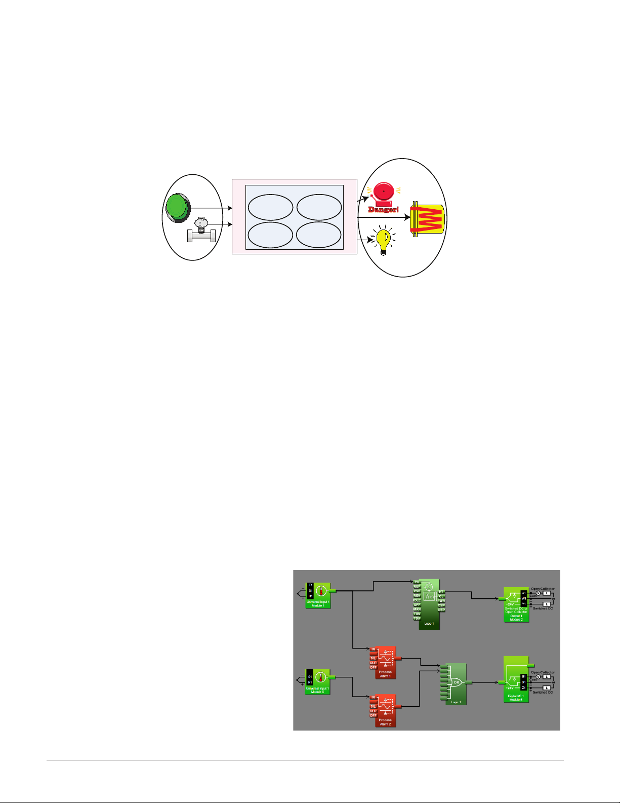
It is useful to think of the controller in three parts: inputs, functions and outputs. For the
control itself, information flows from an input to a function to an output when the controller
is properly configured. The F4T system can carry out several functions at the same time; such
as, monitoring and acting upon various inputs (temperature sensing devices, pressure transducers and digital inputs), PID control, monitoring for several different alarm situations and
then driving output devices such as heaters, audible alarms, and lights. Each process needs
to be thought out carefully and the controller’s inputs, functions and outputs set up properly.
As an example, the graphic below illustrates the Function Block Diagram as seen when using
Composer software. The application requirements in this example are simple and defined below:
• Need two thermocouple inputs.
Functions
PID
Heat
Power
Silence
Alarms
Process
Alarm
High
Sequencing
Outputs
• Monitor both thermocouple inputs for high process alarms.
• Drive an output (alarm) device if either input is higher than expected.
• Use one thermocouple input to drive the PID loop (Heat output) with a switched DC
output.
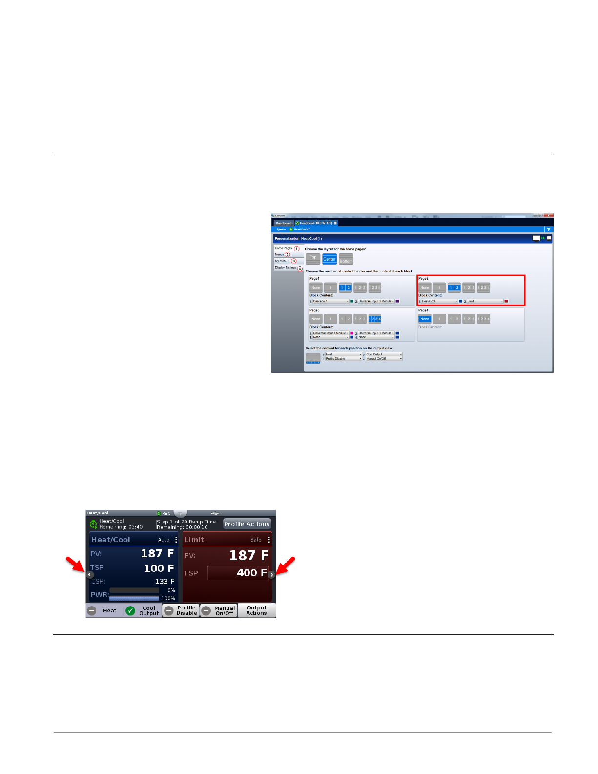
In the graphic below the following is true:
• Universal Input 1 is connected to the Process Value (PV) input of the control loop.
• When the control loop sees that the
PV is less than the user defined set
point it will drive the output to the
load through its heat (HT) output.
• Two unique high process alarms are
configured to monitor Universal Inputs
1 and 2.
• The logic function block (FB) is con-
figured as an OR where its output
will come on if either input comes on
driving the real-world digital output
(alarm) it's connected to.
Watlow F4T • 6 • Chapter 1 Overview
Page 10

Note:
In this configuration, the heat output of the control function would be uninterrupted if an
alarm were to occur.
You will find more detailed information regarding the function blocks and how they work further on in this document.
Inputs
The inputs provide the information that any given programmed function can act upon. In a
simple form, this information may come from an operator pushing a button, or as part of
a more complex function it may represent a remote set point being received from another
zone.
Each universal input can be configured for thermistors, thermocouples, or RTDs to read the
process variable. They can also read mV/volts, current or resistance, enabling usage of various
devices to read humidity, air pressure, operator inputs and other values. The settings associated to each analog input must be configured to match the device connected to that input.
Each digital input reads whether a device is on or off (voltage or resistance) and each system
can be equipped with multiple digital I/O modules. Each I/O point must be configured to function as either an input or output.
Functions
Functions use input signals to calculate a value and or performs an action. A function may be
as simple as reading a digital input as on or off, or reading an analog value (temperature) to
set an alarm state to on or off. As an example, a user could use sensor backup to avoid an unwanted shutdown if a failure with the primary sensing device should occur.
Keep in mind that a FB can be a purely internal function (i.e., control loop, alarm, logic,
etc...), while they can also serve as a connection point between real-world devices (i.e., thermocouple, heater etc...) and internal functions like a Universal Input connected to the Control
Loop PV input. To have an effect outside of the controller, an output FB must be configured
to respond to some other function. Functions and all associated dependencies would be configured using Composer software. To learn more about setting up function blocks see Chapter
2 of this document in the section titled "Configuring the Application with the Function Block
Diagram View".
Watlow F4T • 7 • Chapter 1 Overview
Page 11

Outputs
Outputs respond to information provided by a function such as, heat power from the output
of the control loop, driving a digital output based on a profile event, turn a light on or off,
unlocking a furnace door or turning on a buzzer.
More than one output can be assigned to respond to any given function, i.e., more than one
output device could be connected to the heat output of the control block. Another example
(not shown), could use the (internal) output of the alarm function and connect it to any available real-world output to trigger a flashing light and another real-world output that might be
connected to a siren.
What is a Profile
A profile is a set of instructions consisting of a sequence of steps. When a profile runs, the
controller automatically executes its steps in sequence. The step type determines what action the controller performs. Steps can change temperatures and other process values gradually over time, maintain the temperatures and process values for specific periods, or repeat a
sequence of steps numerous times. At each step the profile can activate or deactivate outputs
that control other equipment. Also a step can have the controller wait for specific conditions
before proceeding such as, waiting for a switch closure and/or a specific process value to be
detected by a sensor.
Data Logging
Controllers equipped with this feature will have the letter [J, K, L or M] in the fifth character
of its part number (see: F4T Ordering Information). Logging can be enabled at any time and is
intended to capture real-time data for a user selectable list of data points. With firmware revision 3.0 and above, several new features are available.
1. User can determine if logged files will be moved automatically and or manually.
2. Destination of the saved file can be directed to internal memory, USB thumb drive, TFTP
server or a Samba shared drive.
3. Based on user choice, files can now be encrypted (filename.enc) for security purposes and
or saved as comma separated values (filename.csv). Creating both file types allows viewing
of the csv file while maintaining the integrity of the encrypted file.
To learn more about configuring these options see the section in this user's guide entitled Set-
ting Up Data Log Files Using Composer.
Watlow F4T • 8 • Chapter 1 Overview
Page 12

2
Chapter 2: Composer® Software
Controller Configuration and Setup
Installing Composer® Software
Locating the Software and System Requirements
Composer software is included on the "Watlow Support Tools" DVD which ships with the product. As an alternative, the software can also be downloaded at: http:// f4t.watlow.com or
http://www.watlow.com/downloads/en/software/composer.cfm
In order to install and run this software successfully there are some baseline requirements for
PC hardware and operating systems that must be observed. These requirements are listed be-
low:
• 250 Megabytes or more of available hard disk drive space
• 300 Megabytes of available RAM
• Supported operating systems include: Windows® 7 / 8 / 8.1 / 10 (32 or 64 bit)
• Requires Microsoft® .NET Framework 4.0 (this installs automatically if not already on
target machine)
Installing the Software
To install the software:
1. Double-click the Setup.exe.
2. Select the language of choice and click the OK to proceed.
3. Click the Next button to proceed.
4. After reading the Composer® software license agreement click the I accept the terms in
the License Agreement radio button and then click on the Next button to proceed.
5. The next dialog box that will appear shows the default directory in which the software
will be installed. The install location can be changed by clicking the Browse button and
then point to the preferred location.
6. Click Next and then Install.
7. Clicking the Finish button will conclude the installation.
Note:
If experiencing difficulties installing or using Composer software, prior to contacting
Watlow technical support, be prepared to send the user log file to the tech support team.
This text file can be found here: C:\Users\username\AppData\Roaming\Watlow\Composer\
Logs
The red text above will change to the user's Windows login name.
Watlow F4T Controller • 9 • Chapter 2 Configuration Using Composer
Page 13
Using Composer® Software
Connecting the PC to the Controller (System) - Physical Connections
Physical connections (hardware and cabling) will vary depending on the controller in use.
1. To find instructions connecting an F4T controller to a PC see: Chapter 3 of the F4T Installation and Troubleshooting User's Guide.
2. To find instructions connecting a Rail Mount (RM) control to a PC see: Chapter 2 Install
and Wire, of the RMC Module User's Guide
Starting Composer Software:
1. Click the Start button and then type composer.exe in the search box.
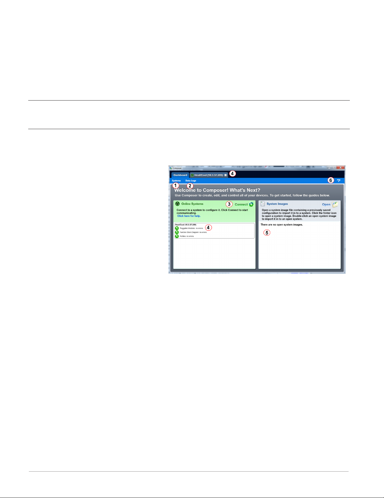
Composer Welcome Screen Orientation
The graphic below illustrates and defines some points of interest as seen on the Composer
Dashboard screen and describes the functionality, numbered correspondingly.
① Dashboard (Systems)
• Displays options for online connections between PC
and a controller or opening a
previously saved system image.
② Data Logs Menu
• Decrypt Log File: allows for decryption of an encrypted data log
file.
• View: displays the contents of a data logged file
(enc or csv). Depending on files size this may take several minutes to open.
To decrypt an encrypted file follow the steps below:
1. If data logging has not yet been stopped do so now by pushing: Main Menu -> Data Logging -> Stop buttons.
Note:
When data logging is stopped, allow at a minimum, six minutes for closure of all
files and movement of those files to the selected destination before attempting decryption.
2. Open up Composer software and click on Data Logs and then Decrypt Log Files.
3. Locate the encrypted files and open them one-by-one (click on one *.enc file and click
Open), or by selecting more than one and click the Open button.
Note:
If logged file is sent to USB, the *.csv and the *.enc file are written directly to USB
constantly. If the File Size Limit is set to 10MB or larger, the csv will continue to be
written continuously while the encrypted portion (*.enc) is chunked into 7.5MB files,
buffered internally and then written out as 7.5MB chunks. If the maximum file size
is set to 10MB, there will be two *.enc files for each csv (7.5MB and 2.5MB). If File
Size Limit is set to 15MB, there would be two 7.5MB *.enc files for each *.csv file.
Watlow F4T Controller • 10 • Chapter 2 Configuration Using Composer
Page 14
Note:
As noted above, if a csv file is greater than 10MB there will be more than one encrypted file for the associated csv file. When decrypting these files, it is recommended that all encrypted files be selected in the decryption process. Each of the
encrypted files will be concatenated into one csv file.
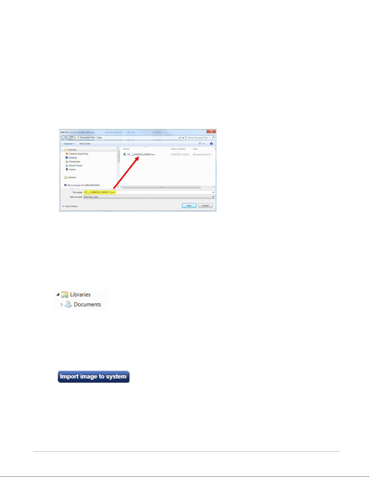
4. After selecting the desired encrypted files and then clicking Open, the window below
will appear. Notice the filename of the original csv and the one suggested in the dialog
box highlighted yellow below. The one within parentheses (1) is inserted to avoid overwriting the original csv file. You may name the file to your liking.
Note:
The largest file size allowed is 1GB. If decrypting a file of this size it could take up
to 10 minutes to complete.
③ Connect to a System
• Opens a window showing all available communications ports.
④ Online Systems
• Displays all connected systems.
⑤ Open a System Image
• Opens a dialog box showing the default folder structure.
To import a system image follow the steps below:
1. Connect to the desired online system described above
2. Click Open to search storage device and find the desired system image
4. Double-click on the desired system image
5. Once the system image is opened click on the button below:
6. Select the system to be configured and click continue
Note:
Use caution when considering this option, once initiated, controller memory will be overwritten in its entirety and replaced with the new system image.
⑥ System Images
• Displays all opened system images.
Watlow F4T Controller • 11 • Chapter 2 Configuration Using Composer
Page 15

⑦ Question Mark (?)
• Allows a user to do the following:
- Update Settings, Change automatic software update settings
- Check For Updates, Initiate an immediate check for software updates (internet connection is required)
- Dashboard Help, Provides description and information pertaining to the Dashboard
- About, Displays technical support contact information as well as the current versions
of the installed software and installed modules.
Overview Screen
Topics discussed in this section follow:
Connecting to an Online System: from the Dashboard connect to an online system.
Overview Screen Orientation: visually identifies all devices connected to the system.
System Menu: when clicked, a drop down submenu will appear.
Device Menus: when clicked, a unique drop down submenu will appear for each device or con-
troller on the system. The menus provide access to device specific screens.
Global Settings: set temperature units and AC line frequency for the system (all controllers).
Security: allows for multiple levels of password protection.
Saving a System Image: save a system image to a storage device.
Import System Image: restore a system image from a storage device to the controller.
The graphic below, shows the first displayed screen (System Overview) after connecting to a
system.
Connecting to an Online System
To connect to a system:
1. On the Dashboard screen click Connect.
2. Select the communications port that the system is connected to and then click Continue.
3. Double-click on the desired online system.
To view the system overview:
1. On the Dashboard under Online Systems, double-click the desired system.
Overview Screen Orientation
The graphic below illustrates and defines some points of interest as seen in the system overview with each identified by a corresponding circled number. Further information for each can
be found just below the orientation.
This screen can be accessed from within any Composer® view always rendering a visual display
of all devices connected on the system while also providing navigation to and from each device.
Watlow F4T Controller • 12 • Chapter 2 Configuration Using Composer
Page 16
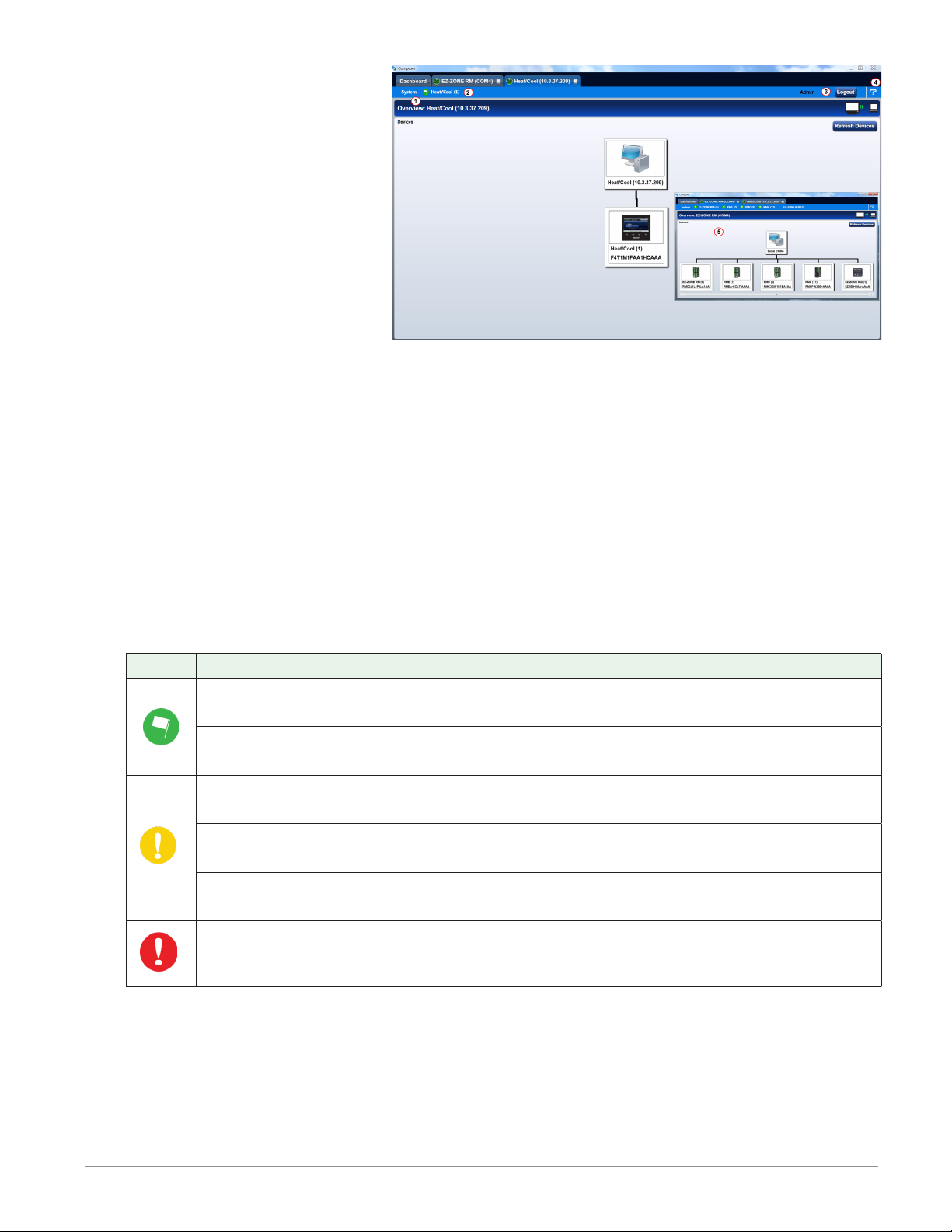
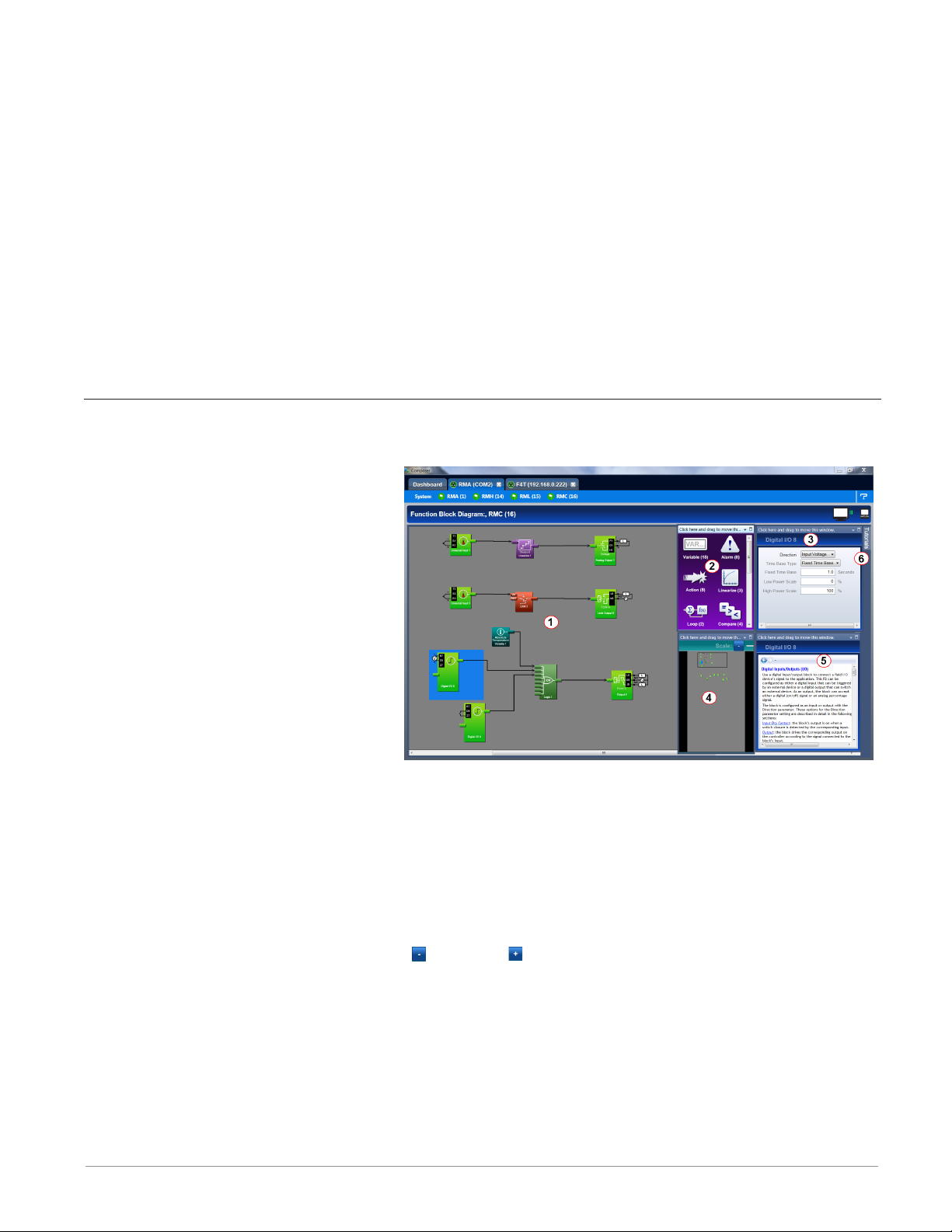
① System Menu
• Overview: displays the
screen shown at the right.
• Save Image: saves a previously saved system image using the same name and the
same destination folder.
• Save Image As: saves system
image with a new name to
the user specified folder.
• Import Image: select a previously saved system image to
download to the device.
• Print: active when viewing the function block diagram. What's printed will be exactly
what can be seen on the canvas. If all FBs are not visible, scale the canvas using the
Navigator plus and minus buttons and then click the System tab and then Print.
• Global Settings: for use throughout the controller changes settings for Temperature
units, AC Line Frequency, and Date and Time.
• Security: allows the administrator to determine and set security privileges to avoid unwanted changes.
② Device Menus
• When clicked, a drop down submenu will appear allowing navigation to device level
menus. Each device will have one of three flags displayed immediately to its left.
Those flags are described in the following table.
Symbol Menu Item Description
Pluggable
Modules
Function Block
Diagram
Pluggable
Modules
Function Block
Diagram
Profile Editor
Pluggable
Modules
All expected modules and no unexpected modules are present
(F4T only).
No signals have errors.
A module has been detected in a slot the controller expects
to be empty (F4T only).
At least one unexpected module has been detected, however,
all expected modules are present.
One or more of the profiles were created for a different configuration and cannot be run (F4T only).
At least one expected module is missing (F4T only).
③ Security
• When enabled, displays current level of access with the ability to logout.
④ Question Mark (?)
• Provides help for each of the options mentioned above.
⑤ Inset Picture of Rail Mount (RM) modules connected as a system.
Watlow F4T Controller • 13 • Chapter 2 Configuration Using Composer
Page 17

Global Settings
Each of the settings below will be used and applied throughout the controller.
• Temperature Units: will determine how the temperature is displayed (Fahrenheit or
Celsius) on the front panel of the controller as well as throughout all configuration
screens within Composer®.
• AC Line Frequency: set this to the line frequency of the power applied to loads such
as heaters (50 Hz or 60 Hz) so that the current sensing and variable time-base features
will work correctly.
• Date and Time: sets the date, time and time zone to the current computer settings or
whatever the user enters.
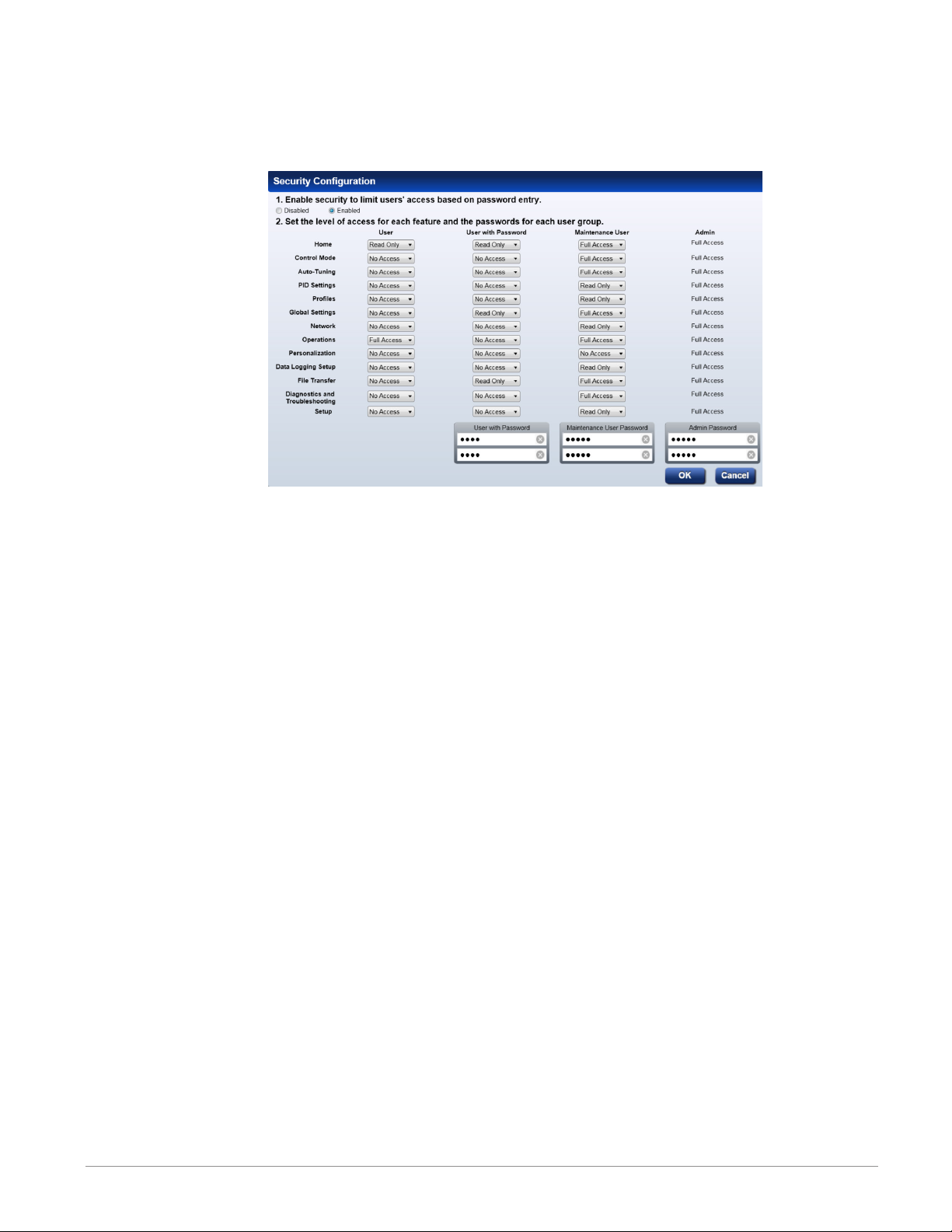
Security
The security feature is used to protect the system's configuration and settings from unwanted
changes. The Admin user sets what access other users have to the system's features. When security is enabled, a user must enter a password to gain access to protected features through
the controller's user interface or Composer software.
There are three configurable user groups and an admin account:
• User: no password required, admin sets feature access
• User with Password: requires a password, admin sets feature access, is permitted to
change the password for this user group.
• Maintenance User: requires a password, admin sets feature access, is permitted to change
the password for this user group.
• Admin: requires a password, has unlimited access to features, sets permissions and passwords for all user groups.
The Admin user can set permissions for each user group to allow full, read-only or no access
to the following features:
• Home: controls access to controller's home screen.*
• Control Mode: controls access to setting the control mode, set points and PID parameters.
• Autotune: controls access to running the autotune feature.
• PID Settings: controls access to the PID settings.
• Profiles: controls access to creating and editing ramp and soak profiles.
• Global Settings: controls access to the system's global settings, temperature units, AC
line frequency and real time clock setting.
• Network: controls access to communications settings.
• Operations: controls access to operational parameter settings.*
• Personalization: controls access to customizing the controller's home screen.
• Data Logging Setup: determines frequency of logging, location of saved files and other
general information.
• File Transfer: allows a user to transfer files (Configuration, Profile and Data log) to/
from the controller.
Watlow F4T Controller • 14 • Chapter 2 Configuration Using Composer
Page 18
• Diagnostics and Troubleshooting: controls access to the device details and calibration.
• Setup: controls access to the pluggable module configuration and the function block
diagram.
*This setting limits access to the controller's User Interface (UI) only, not via Composer®.
Note:
After making all of the desired security settings, ensure that the security enabled radio
button (top left in the graphic above) is selected Enabled.
Note:
If the passwords have been misplaced or forgotten it will be necessary to contact the OEM
or as a last resort Watlow Technical Assistance.
Note:
Once security is applied to the controller, only the administrator (Admin) can reconfigure
or remove the security.
Note:
When the system file is saved, any applied security will be saved with it.
Save Image
After clicking on save image as, the save button will become active (gray to white). This allows a user to make changes to the system image and simply save it to the same location using the same filename. Everything that will be saved is as listed below:
• Device Details
• Pluggable Modules (F4T only)
• Function Block Diagram in its entirety
• System Security
• Profiles (F4T with profile option only)
• Profile passwords (F4T with profile option only)
• All parameters that can be read and written to
Watlow F4T Controller • 15 • Chapter 2 Configuration Using Composer
Page 19
Save Image As
• Allows user to specify a name and storage location while saving everything in the list
above.
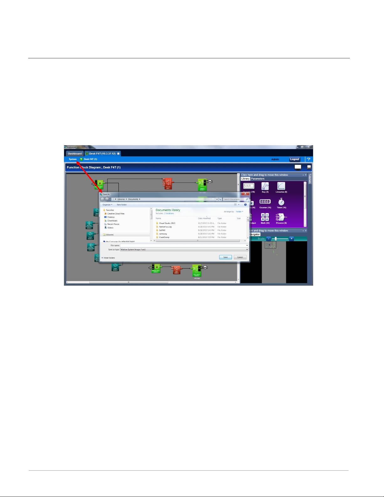
Saving a System Image
To save a system image the first time:
1. From any screen click on the System Menu tab to drop down a submenu.
2. Click the Save Image As button.
3. Use the save as dialog to select the destination folder for the image.
4. Enter the desired filename.
5. Click Save.
Note:
The system image filename will always have the extension wsi for Watlow System Image
and cannot be changed.
Note:
The real-time clock values are not saved or imported.
Import Image
• Restore a system image from a storage device to the controller. The list below shows
what is restored:
- Device Details
- Pluggable Modules (F4T only)
- Function Block Diagram in its entirety
- System Security
- Profiles (F4T with profile option only)
- Profile passwords (F4T with profile option only)
- All parameters that can be read and written to
Watlow F4T Controller • 16 • Chapter 2 Configuration Using Composer
Page 20
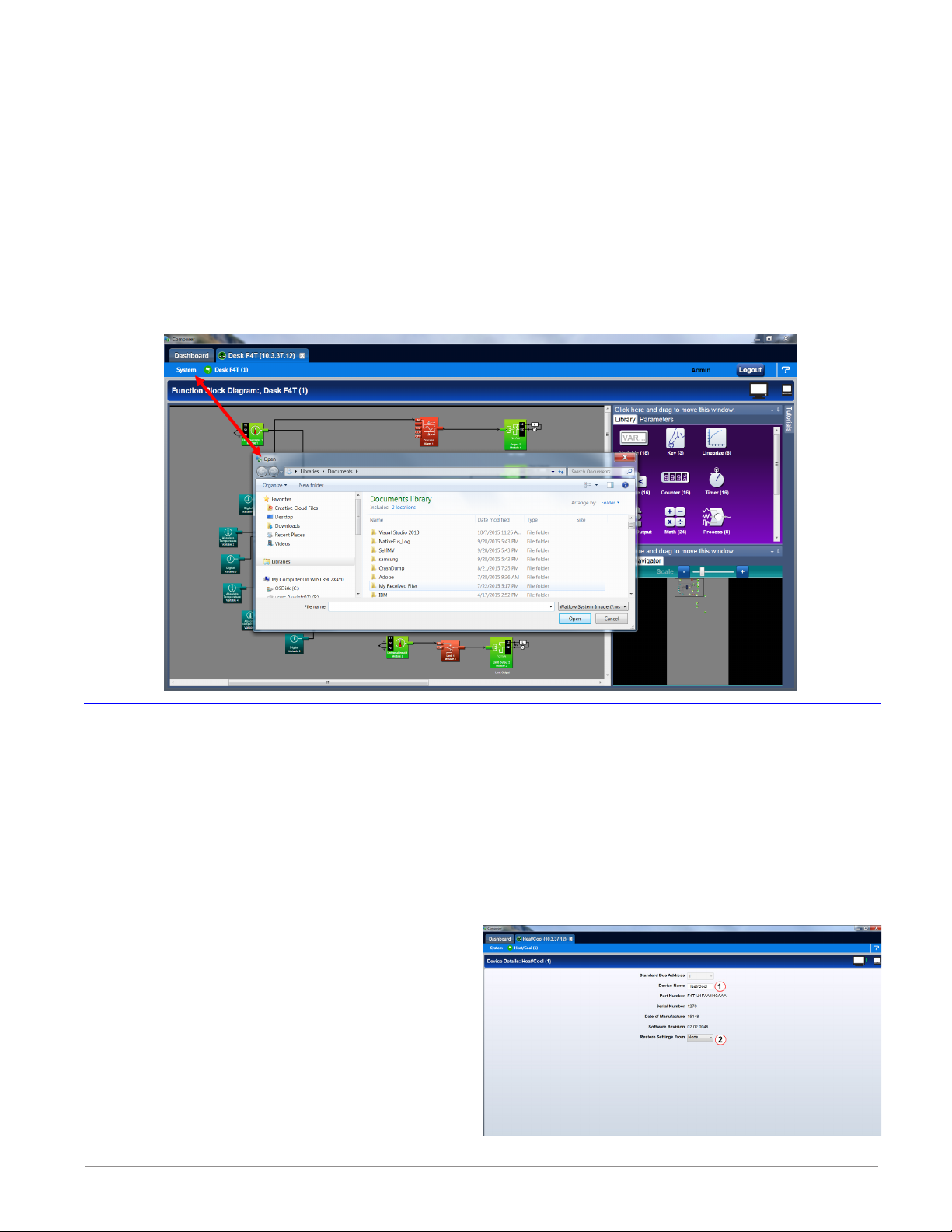
Importing a System Image
To import a system image:
1. From any screen click on the System menu tab to drop down a submenu.
2. Click the Import Image button.
2. Use the open dialog to select the folder location for the previously saved system image.
3. Double-click the desired filename or single-click the filename and then click the Open
button.
Note:
Importing a system image will overwrite the controller in its entirety. Careful thought
should be applied prior to importing.
Device Details
The Device Details allows a user to make changes to the system settings described below. Descriptions are numbered correspondingly in the graphic that follows.
Navigate to Device Details:
1. From any screen click on the Device menu tab to drop down a submenu.
2. Click the Device Details button.
Device Name - change the name (32 characters maximum) of the controller for easy identi-
①
fication.
Note:
This name will also be displayed in the upper left corner of the user interface.
Restore Settings From
②
• None: no action.
• Factory: allows a user to bring the
controller back to the factory default
state.
Watlow F4T Controller • 17 • Chapter 2 Configuration Using Composer
Page 21
Configuring Pluggable Flex Modules
This controller can have up to six Flex Modules (FM) installed in the chassis. The presence of
each FM must be confirmed and accepted using Composer® software. FMs can be fully configured as installed hardware or the user can type in a valid FM part number for later installation. For more detail regarding the module installation process, see the Installation and Troubleshooting User's Guide for the controller in use.
Note:
Typing in a valid part number without the presence of the module is intended for the sole
purpose of building the FBD (connecting function blocks on the canvas). Errors may be
generated and all outputs will be off until the module is inserted.
Topics discussed in this section follow:
Screen Orientation: detailed description of the Pluggable Module configuration screen and as-
sociated characteristics.
Symbols Related to Pluggable Modules: description of the symbols that may be displayed when
using Composer software.
Configuring Flex Modules: configuration process described.
Entering FM Information Before Module Installation: detailed description of the why and how
a user would do this prior to acquiring the module.
Note:
The graphic below represents a controller that first had its flex modules installed with the
controller then being connected to a computer. Because of this scenario each slot appears
with no expected modules. This screen and symbols that are displayed will look different
using a different scenario.
Navigate to Pluggable Modules screen:
1. From any screen click on the Device Menu tab to drop down a submenu.
2. Click the Pluggable Modules button.
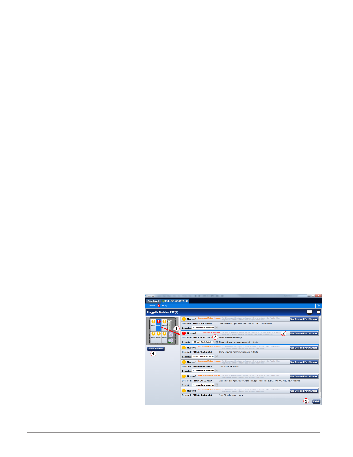
Pluggable Flex Modules - Screen Orientation
Module Slot - Location
①
• The blue box (on the right)
and the slot highlight will
move with the mouse to bring
focus to the slot/module.
Use Detected Part Number
②
• Click this button to accept
the module that the system
sees as being present in the
slot and displayed in the field
identified as "Detected Part
Number".
Set Expected To None
③
• Click on the X to tell the system there will be no module installed in this slot. Taking
Watlow F4T Controller • 18 • Chapter 2 Configuration Using Composer
Page 22
this action will turn the power off for this slot after the controller is reset.
Detect Modules
④
• The controller will shut off all outputs and initiate an evaluation of each slot to see if
any modules are present.
Note:
In the graphic above, if a module were inserted in slot 3, clicking detect modules will turn
the power on for the slot and report back with the module part number installed.
Finish
⑤
• Will cause the controller to restart and take the user to the Function Block Diagram.
Note:
There are some FM slot dependencies. If there is a question as to whether or not an FM is
in an acceptable slot, refer to the Installation and Troubleshooting Guide for the controller
in use.
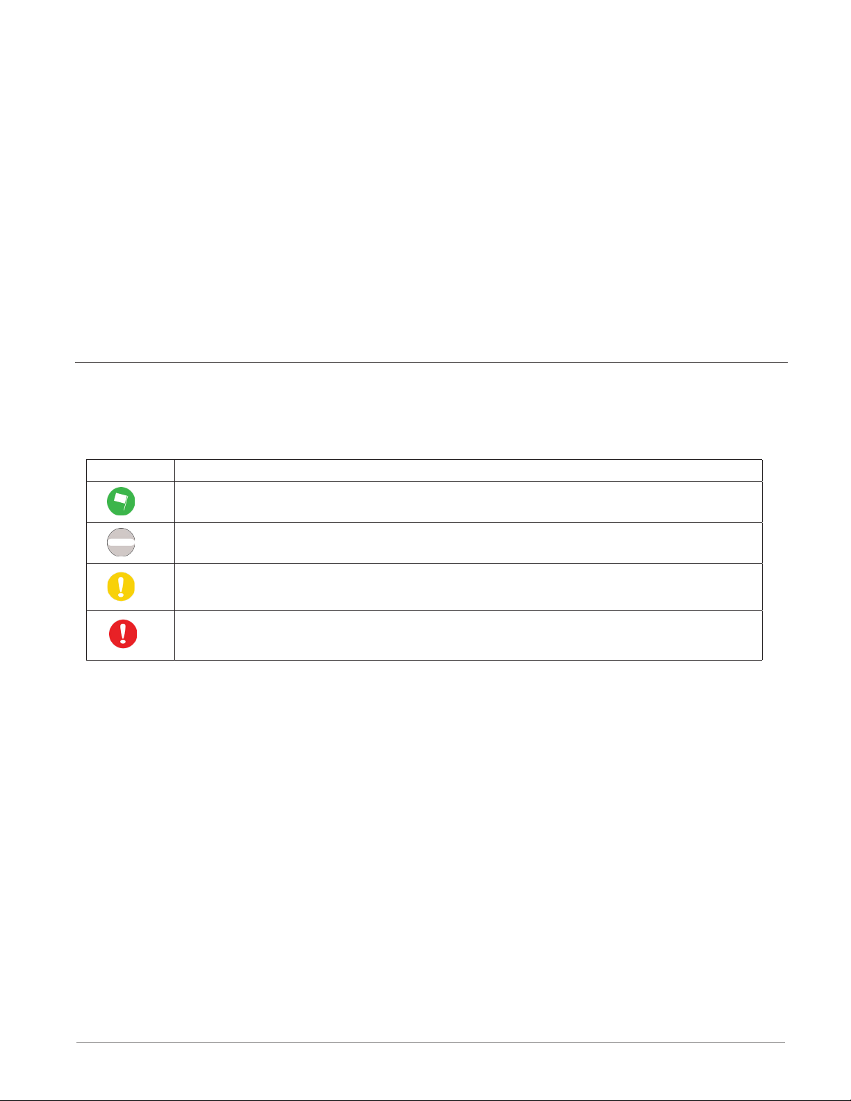
Symbols Related to Pluggable Modules
As viewed from the Menu bar, the symbol that will be displayed to the left of the
Pluggable Modules button will be of the most significance. The red exclamation will always take precedence.
Symbol Description
The expected module has been detected.
No module has been detected in a slot the controller expects to be empty.
A module has been detected in a slot the controller expects to be empty.
The controller expects a module, but that module is missing or a different
module has been detected.
Configuring Flex Modules
To accept the detected modules:
Note:
If modules were plugged in after powering up or resetting the controller, click on the Detect Modules button to restart the controller and detect all of the modules that are pres-
ent.
1. On the right side of the screen click the Use Detected Part Number button.
2. Repeat step 1 for each slot to be configured.
3. Click the Finish button to restart the controller and exit to the Function Block Editor.
Note:
Exiting the pluggable modules screen after any changes are made will cause the controller
to restart. A restart will stop all controller activities while turning off all outputs.
Watlow F4T Controller • 19 • Chapter 2 Configuration Using Composer
Page 23
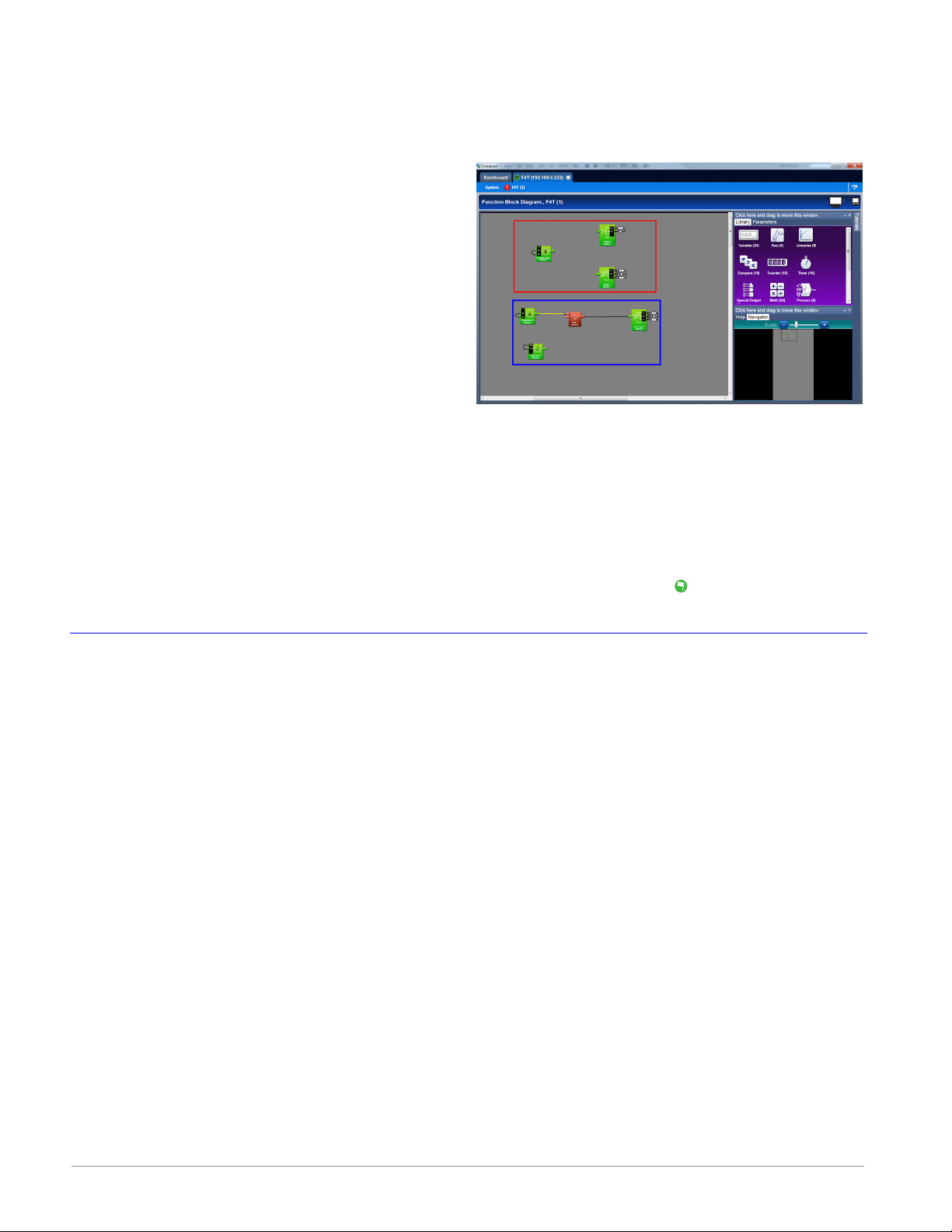
Entering Flex Module Information Prior to Installation
Function blocks associated with hardware will not be available until the hardware is expected
to be present. Entering a part number for any slot (even though the module is not currently
installed) allows the programmer access to the associated function blocks. As an example, if
an FMMA-UEKA-AAAA is installed in slot one,
the function blocks that would be available are
shown in the red box. After entering a part
number such as FMLA-YEBA-AAAA in slot 2, additional hardware dependent function blocks
will appear as shown in the blue box.
Note:
When configuring modules as described
above (not installed), the controller will not
be able to control any outputs. All outputs
will be off.
To configure the controller to expect a module that is not yet installed:
1. Select the desired slot and enter a valid part number in the Expected Part Number field.
2. On the keyboard, push the Enter key.
3. Click Finish when complete to restart the controller. After the restart process is complete
the Function Block Diagram will appear.
Once the module is acquired, simply plug it into its assigned slot and click the Detect Mod-
ules button. After doing so, the controller will restart and a green flag will be displayed for
that slot number.
Configuring the Application using the Function Block Diagram
The Function Block Diagram (FBD) view is used to connect the real-world inputs and outputs
to internal controller functions, such as alarms, control loops and ramp and soak profiling.
To enter the Function Block Diagram:
1. Click on the desired Device menu.
2. From the drop down menu click Function Block Diagram.
Topics discussed in this section follow:
Screen Orientation: detailed description of the FBD screen and associated characteristics.
Customizing the FBD Environment: change default canvas settings to user preference.
Window Anchor Points: defines a new docking location.
Getting Started: things a user will encounter on the canvas while building the application.
Selecting and Placing FBs on the Canvas: describes where to find and then place selected FBs
on the canvas.
Moving FBs on the Canvas: describes how to move selected FBs on the canvas.
Connecting FBs Together: describes how to make the application come to life by interconnect-
ing FBs.
Viewing Signal Values and Errors: describes how to view signal values and errors as they oc-
cur.
Watlow F4T Controller • 20 • Chapter 2 Configuration Using Composer
Page 24
Troubleshooting Signal Errors: suggestions in how to evaluate a signal error.
Adjusting FB Behavior with Parameter Settings: change the functionality of a FB based on its
parameter settings.
Finding Help for FBs: describes how to acquire embedded help for each FB.
Changing and Deleting Signals: making modifications to the program through new and revised
FB connections.
Removing FBs from the Canvas: describes how to delete FBs on the canvas.
Using Auto Hide: maximize visibility of available screen space by hiding infrequently used win-
dows.
Floating a Window: move a window from its docked location to a user defined location.
Docking a Window: describes how to create new or return to previous docking locations.
Turning Floating Windows Off and On: describes how to enable and disable floating screens.
Function Block Diagram View - Screen Orientation
The FBD View has the following features, numbered correspondingly in the graphic below.
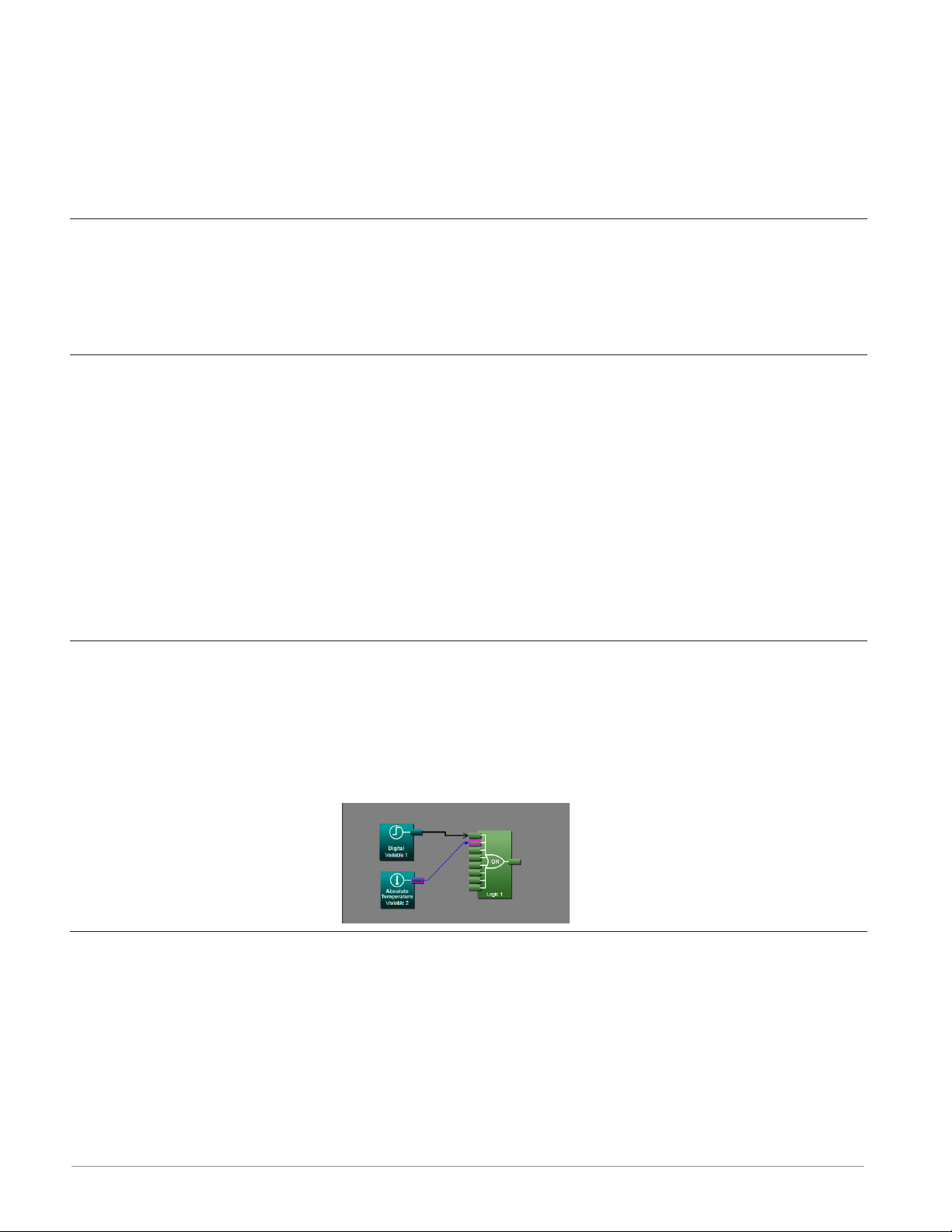
Function Block Diagram
①
• All FBs are placed and connected on the canvas.
Function Block Library
②
• Shows the available FBs for
this controller. The number
below each icon indicates how
many FBs of that type remain
available for use with this
controller. As is displayed in
this graphic, this window is
movable and dockable.
Parameter List
③
• Used to view and set the FBs parameters customizing its behavior for the application.
This window is movable and dockable.
Navigator
④
• Allows the user to adjust the view of the canvas. Drag the box to reposition the
view.
• Use the slide bar or the min+us and plus buttons to adjust the zoom level. This
⑤
window is movable and dockable.
Help
• To view detailed FB information click on any FB. This window is movable and
dockable.
Tuto r ials
⑥
• Topic based video help files.
Watlow F4T Controller • 21 • Chapter 2 Configuration Using Composer
Page 25
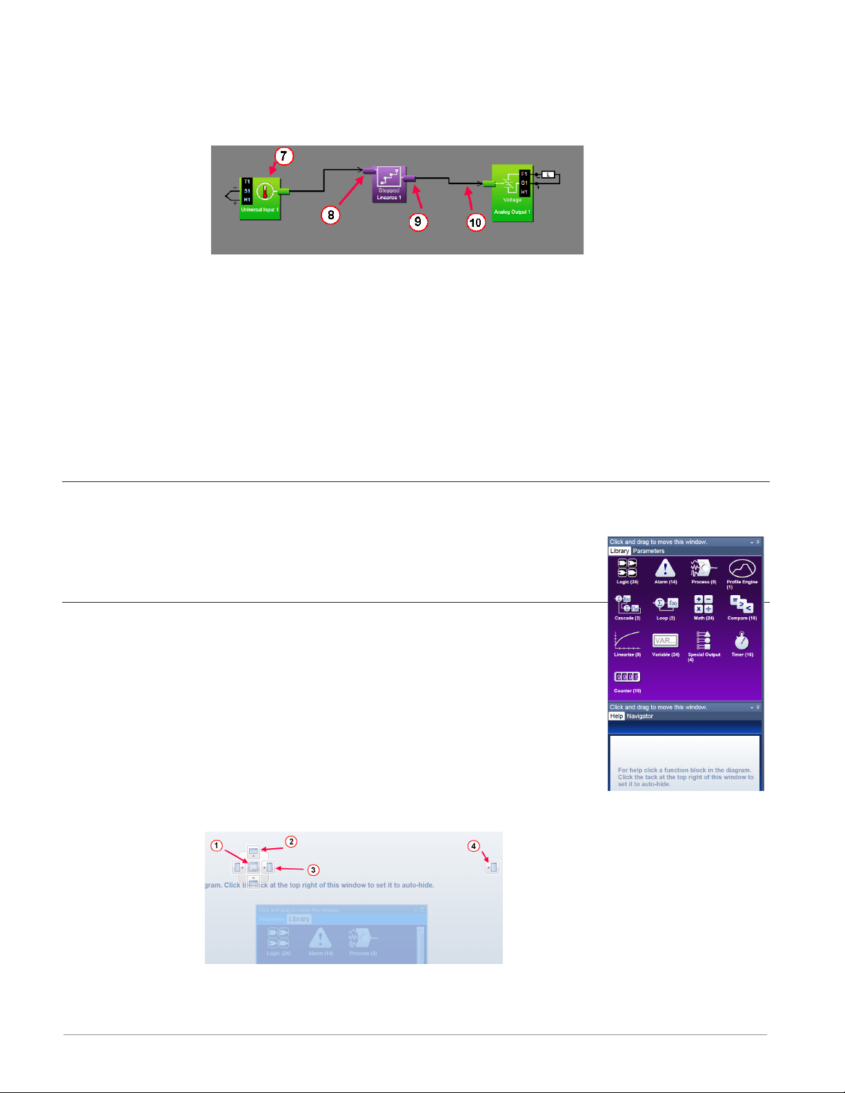
Function Blocks (FBs)
⑦
• Allows the user to customize the functionality of the controller for a specific application. Some FBs are interfaces to real-world I/O devices and some serve as the interface to internal functions such as, the compare, logic and math FBs.
Receiver
⑧
• The part of a FB to which a signal can be connected in order to supply data to the
function.
Transmitter
⑨
• The part of a FB from which a signal can be connected in order to carry data to another FB.
Signal
⑩
• A line that represents the connection of data from one FB to another.
Customizing the Function Block Diagram Environment
The Parameter, Help, Library and Navigator windows can be moved from their default locations to allow a user to maximize the visibility of the FBD diagram. See
the procedures below regarding how to float, hide and dock these windows.
Window Anchor Points
While dragging a window or a grouping of windows to a new docking
location Anchor Points will appear on the screen. The anchor points in
the graphic are numbered corresponding to their associated descriptions
below:
① Drag
②
e
r
the window here to add to the window group.
Drag window here to dock above the window group.
Drag window here to dock to the right of the window group.
Drag window here to dock at the right of the screen.
Watlow F4T Controller • 22 • Chapter 2 Configuration Using Composer
Page 26

Getting Started with the Function Block Diagram (FBD)
The basic steps for creating the function block diagram for any application are:
1. Add the function blocks from the library to the canvas that are needed to interpret the
signals from the physical inputs and set the physical outputs. Typically, these will include
Loop, Alarm and Profile Engine function blocks.
2. Connect the transmitters on the FBs that source data to the receivers on the FBs that
need the data.
3. Set each function block's parameters as needed for the application to perform as expected.
Detailed descriptions of each function block including all the function block's parameters can
be accessed in the online help for the function block and in the User's Guide, chapter entitled
Function Block Reference.
The FBs that represent the physical inputs and outputs from the controller and are associated
with the flex modules that are expected in the configuration are always on the canvas. These
FBs can only be removed by changing which modules are expected using the Pluggable Modules view.
Other FBs can be added to the canvas from the library. Some of these FBs such as Loop, Cascade, Alarm and Profile Engine perform sophisticated functions. See the Application Examples
chapter in this User's Guide for more on these functions. Other function blocks such as Math
and Logic perform fundamental functions that can be combined to add custom behaviors to
the controller for specific applications.
The signals that carry data between function blocks normally appear as black lines in the diagram, but when the block that transmits the signal cannot determine what the correct value
should be, the signal changes to yellow indicating the error. Each FB's response to errors received is explained in the description of the function block.
Warning:
Once an output FB receiver is connected to another block, the output on the flex module
turns on according to the received signal. Do not connect outputs until it is safe to do so.
Notable facts about the FBD:
• How a FB responds to its inputs and drives its output is dependent on its parameter settings. Set the parameters for each function block as needed for the application.
• Signals cannot be moved after they are created; to change where a signal gets data or
where it delivers it, delete the signal and create the desired connection.
• There are several ways to do many things. Try right-clicking to see options or short
cuts.
• FBs from the library that have no signals connected are returned to the library when
Composer® is closed.
• The location of dockable windows is not saved; windows return to their default locations when the system is closed.
• The selection of signal values displayed in the diagram is not saved; all signal value displays are turned off when the system is closed.
Watlow F4T Controller • 23 • Chapter 2 Configuration Using Composer
Page 27
Hints:
• Click-and-drag any blank spot on the canvas to change the view.
• Use the scroll bars.
• Use the Navigator to reposition the view of the canvas and to zoom in or out.
• Use the mouse wheel to scroll the view. Hold the shift key to use the mouse wheel to
pan. Hold the Control key to use the mouse wheel to zoom.
Selecting and Placing Function Blocks on the Canvas
To place a FB on the Canvas:
1. Find the desired FB within the library (using scroll bars if present).
2. Click-and-drag the FB to the canvas.
Moving Function Blocks
To move a FB on the Canvas:
• Click-and-drag the FB to the desired location on the canvas.
Hints:
• Click the main body of the FB not one of its transmitters or receivers. Clicking a transmitter or receiver begins to draw a signal rather than move the FB.
• The canvas will scroll if the mouse pointer is close to the edge but not outside the diagram window.
• To make a long move, click the block to select it, then zoom out to make it easier to
move the block to the desired location.
Connecting Function Blocks Together
To connect a transmitter to a receiver:
• Click and drag a signal from a FB's transmitter to a receiver on another FB.
Hint:
• This can also be accomplished in reverse, i.e., click and drag from a receiver to a transmitter.
Viewing Signal Values and Errors
To momentarily display a signal's value:
• Mouse over (point the mouse cursor at) the signal.
To display a signal's value continuously:
1. Right-click the signal.
2. Click Show/Hide Data
Watlow F4T Controller • 24 • Chapter 2 Configuration Using Composer
Page 28

To cancel (turn off) the signal display:
1. Right-click the signal.
2. Click Show/Hide Data
Note:
The values displayed are not in real-time.
Troubleshooting Signal Errors
While building the FB diagram, or during operation, there may be occasions when the signal
from the transmitter of a FB is displayed yellow. This may reflect that the FB has encountered
an error or some other anomaly has occurred. From the user perspective, an evaluation of the
cause should be done to ensure that unexpected operation does not occur. Suggested steps to
evaluate the cause of a yellow link are listed below:
To evaluate the cause of a yellow signal:
1. Trace the yellow signal back to the source
(first occurrence of a yellow link) FB.
2. Place the mouse over the signal which
will display the error.
3. In this particular example, the error is identified as an Open sensor.
4. Click on the selected FB and view the Help window.
5. Search ("Ctrl-F") the help file for the word "Open".
6. Once found, evaluate, make note or correct the cause of the problem.
If further assistance is needed review the associated product User's Guides or contact the
Watlow Technical Support team (1-800-492-8569 or 1-507-494-5656).
Adjusting Function Block Behavior with Parameter Settings
To change a FB parameter:
1. Double-click on the FB.
2. In the Parameters window locate and change the parameter.
Note:
If names are applied here, those names will appear on the FBD
and if selected, the output view of the Personalization screen.
Finding Help for Function Blocks
To locate the help topic for a FB on the Canvas:
• Click the FB and view the help window.
Watlow F4T Controller • 25 • Chapter 2 Configuration Using Composer
Page 29

Hints:
• Many function blocks can be configured to perform one of several functions. For these
FBs, the help topic has a section for each function. Locate and click the link for the desired function.
Changing and Deleting Signals
To delete a signal:
1. Click the signal to select it.
2. Press the Delete key on the keyboard.
Note:
To change where a signal connects, first delete it then make the desired connection.
Removing Function Blocks from the Canvas
To remove a FB from the Canvas:
1. Delete all signals connected to the FB.
2. Click the FB to select it.
3. Press the Delete key on the keyboard.
Using Auto Hide
To toggle the auto hide option for a window or a group of windows:
• Click the pin (auto hide) icon in the window's title bar.
To use a window that is hidden:
• Mouse over (point the mouse cursor at) the window name.
Floating Windows
To float a window or a group of windows:
• Click-and-drag the window's title bar to the desired location.
To separate a window from a group:
• Click-and-drag the window name to the desired location.
Docking Windows
To return a floating window or a group of windows to its previous docking location:
• Double-click the title bar.
To change where a window or a group of windows is docked:
1. Click-and-drag the window's title bar until the anchor points appear
2. Drag the window until the mouse pointer is at the desired anchor point.
3. Release the mouse.
Hint:
• Some anchor points dock the window at the sides of the FBD view and others dock or
group the window with other windows.
Watlow F4T Controller • 26 • Chapter 2 Configuration Using Composer
Page 30
Turn Floating Windows Off or On
To avoid the possibility of inadvertent window movement, this feature can be turned off.
To turn floating windows off:
• Right-click anywhere on the canvas and choose Turn off float in the pop-up menu.
To turn floating windows on:
• Right-click anywhere on the canvas and choose Turn on float in the pop-up menu.
Personalizing the User Interface (UI) Using Composer
The home screen of the F4T controller can be personalized to show multiple pages and multiple content blocks within each (4 maximum). Until personalized, the home screen will be
blank. Features that are available on
the Personalization screen are numbered corresponding to their associated
descriptions below:
Home screen can be modified in ac-
①
cordance with installed hardware
and named FBs on the FBD
Modify user interface (UI) button col-
②
.
ors
Create a customized menu to be
e
viewed on the UI.
Change the user interface screen brightness.
r
To personalize the home screen:
• From the device menu choose Personalization from the drop down menu.
Much, if not all of what is displayed on the home pages comes from the FBD. Therefore, it
would make sense to first configure the FBD prior to personalizing the home screen.
.
®
The personalization settings shown above would produce a home page like the one below. Because it was the second page configured as shown above (red box), notice the arrow buttons
on the right and left of screen capture below allowing navigation to page 1 and 3.
Setting Up Data Log Files Using Composer
Data Logging can be enabled at any time and will log a user selectable list of data points.
While data logging is enabled, the data log file is stored within either the USB device memory
or internal memory. Once the file reaches a specified size (if being transferred automatically),
it will be sent directly to one of three other destinations (USB, TFTP server or a Samba server). The file transfer can also be initiated manually at any time. The file transfer process from
Watlow F4T Controller • 27 • Chapter 2 Configuration Using Composer
®
Page 31

internal memory, whether completed automatically or manually, will move all log files from
internal memory to the selected destination. To learn more about data logging see "Data
Logging" in the Overview Section of this User Guide.
Note:
Data logging can also be enabled/configured through Modbus. There are specific Modbus
registers for each of the parameters defined below. If interested in identifying those registers, see the section entitled "Enabling Data Logging Using Modbus" in the Appendix of this
User's Guide.
Topics discussed in this section follow:
Setup Data Logging: discusses required fields that must be set prior to starting data logging.
Configuring a Samba Shared Folder: identifies and gives illustrations in defining the necessary
user account and the shared folder.
Configuring a TFTP Server: details required setup fields while illustrating steps to successfully
move files from the F4T to the TFTP destination.
Note:
Data logging is terminated when power is lost while the data log file itself will be maintained where it was captured.
Setup Data Logging
To setup data logging, follow the steps below:
1. Click on the Device Menu tab.
2. From the drop down menu click on Data Logging.
3. Select and add all of the desired Data Points for the data log file.
Note:
Selected data points will be used whenever data logging is enabled.
4. Click on the Setup button.
- Logging Status: indicates whether or not recording is active or not.
- File Name: any alphanumeric characters, 63 maximum.
Note:
When transferring files via TFTP, do not create a file on the server called "testfile".
Communications between the F4T and the TFTP server is tested prior to starting a
transfer using this filename while then verifying the response from the server.
- Log To: USB or Internal Memory.
Note:
When transferring files via TFTP or Samba, internal memory must be selected here.
Note:
There are many USB memory devices available. Watlow does not recommend using
micro SD or SD card to USB adapters in the USB slots. Be aware that we have not
tested all of the variations of USB memory devices but we have tested and validated those that are listed below:
• Lexar, Kingston, Toshiba and Verbatim
Note:
Supported USB file systems: FAT16 and FAT32.
Watlow F4T Controller • 28 • Chapter 2 Configuration Using Composer
Page 32

Note:
Due to wear-leveling operations of flash memory devices (internal - F4T and exter-
nal - USB), there may be some gaps within the data logged file.
Note:
If logged file is sent to USB, the *.csv and the *.enc file are written directly to
USB constantly. If the File Size Limit is set to 10MB or larger, the csv will continue
to be written continuously while the encrypted portion (*.enc) is chunked into
7.5MB files, buffered internally and then written out as 7.5MB chunks. If the maximum file size is set to 10MB, there will be two *.enc files for each csv (7.5MB and
2.5MB). If File Size Limit is set to 15MB, there would be two 7.5MB *.enc files for
each *.csv file.
- Log Interval: defines the frequency in which the log will be written, 0.1 second to 60
minutes.
- File Type: Encrypted (filename.enc), comma separated values (filename.csv) or Both.
- File Size Limit: 20MB maximum when using internal memory, 1GB when using USB.
- Memory Full Action: when selected log to device is full, Overwrite or Stop.
Note:
Logging to USB allows for Stop only, when memory is full.
- Date Format: MM/DD/YYYY or DD/MM/YYYY.
Note:
Applies to each individual log entry alone, does not apply to filename.
- Time Format: 12 or 24 hour clock.
Note:
Applies to each individual log entry alone, does not apply to filename.
5. Click on the File Transfer button.
- Auto Transfer Type: None, TFTP, Samba or USB.
Note:
When automatic file transfer is enabled, the file as it's being created, will be buff-
ered in internal memory. The file will be moved to its destination when it either
reaches the maximum file size setting or the user stops data logging. If automatic
transfer fails for any reason, data logging will continue and the files will be stored
in internal memory until internal memory fills up. The setting for Memory Full Action (Overwrite or Stop) will then be implemented.
Note:
A user can initiate a file transfer manually at any time if one or more of the avail-
able destinations (USB, TFTP or Samba) have been configured.
- Samba User Name: Windows user account name with access to shared directory.
Note:
If using Asian fonts, you may need to create a Latin character set login for use with
Samba transfers.
- Samba Password: Windows user account password.
Watlow F4T Controller • 29 • Chapter 2 Configuration Using Composer
Page 33

Note:
If using Asian fonts, you may need to create a user, and password, using the Latin
character set.
- Samba Path: shared directory path and name.
Note:
If using Asian fonts in the path name, please try using latin characters, or numbers
as your folder name, and share name.
- Remote IP Address: the IP address of the remote computer.
- Remote Host Name: the name of the remote computer.
- Transfer Progress: when a transfer is initiated this will reflect its progress from 0% to
100%.
Note:
If an error were to occur, as described below, this value could exceed 100.
- Transfer Results, will return the enumerated values shown below:
• Not configured, no activ-
Blank Nothing to report
No Files to Transfer
Transfer Complete
Transferring Files
Server Down
Need Host IP IP address not present
No data log files in internal memory
All data log files have
been moved from internal memory
Data log files being
moved from internal
memory
Connectivity from client
to server not present
ity.
• Transfer not initiated.
• Data logging has not yet
been started.
• Files have already been
moved from internal
memory.
• File transfer initiated and
completed successfully.
• File transfer initiated and
in progress.
• Server not present.
• Server not configured or
configured incorrectly.
• No connectivity between
PC and F4T.
• Incorrect IP address entered.
- - - -
- - - -
- - - -
- - - -
Samba
• Check and ensure user account info
(name and password) is correct.
• Check and ensure that the shared
folder name is correct and shared
with the user account mentioned
above.
TFTP
• Ensure server is running and configured for read/write capability.
TFTP
• Verify a physical connection between
PC and F4T.
• Check the controller IP address from
the F4T front panel: push Main Menu >
Settings > Network > Ethernet.
• Ping the F4T to verify its presence on
the network.
Watlow F4T Controller • 30 • Chapter 2 Configuration Using Composer
Page 34

Enumerated Value Description Possible Causes Corrective Action
Need Host Name
and IP
Error
Check Directory Permissions, Host Name
and IP Address
Missing host name or IP
address
File transfer did not occur successfully
• Not configured.
• Incorrect IP address or
host name entered.
• TFTP server configuration
not correct.
• Not configured.
• Incorrect IP address or
host name entered.
• Shared folder does not
have correct permissions.
Samba
• Ensure the computer name (Host) is
correct. Click on the Windows Start
button and type my computer in the
search field.
• Verify IP address (see: Need IP Address above).
TFTP
• Server not configured with overwrite
capability, reconfigure server.
• Ensure server is not set for read only.
Samba
• Ensure the shared folder name exists
and that it is being shared with the
user account (Samba User Name).
• Verify IP address (see: Need IP Address above).
• See the section entitled Configuring a
Samba Shared Folder below.
Configuring a Samba Shared Folder
Samba, also known as Server Message Block (SMB)/Common Internet File System (CIFS), is fully
supported by Windows File Sharing. Within this document, SMB/CIFS will be referred to as
Samba.
Samba, when in use, creates a directory on the F4T device that maps to a shared directory on
the user’s PC. There are several ways that a Windows shared drive can be configured. With
this is mind, one of those ways will be discussed and used for demonstration purposes below.
Note:
If a user account already exists with full Administrator rights, steps 1 through 12 can be
skipped.
Setting up a Windows shared drive:
1. Click the Windows Start button and type us-
er accounts in the search box.
2. When the Make changes to your user ac-
count window opens, click on Manage User
Accounts.
3. When the User Accounts window opens, click
on the Advance tab.
4. Under Advance user management, click on
the Advance button.
5. Under the Name column right-click on Users
and then New User.
6. In this example the new user will be identified as "Samba" and will be entered into the
User name field as shown to the right.
Watlow F4T Controller • 31 • Chapter 2 Configuration Using Composer
Page 35

Note:
To ensure that there will be no changes required regarding the password, check Password
never expires.
7. Click on Create and then Close.
8. Click on the X (top right corner) to close the users window.
9. If not already open, navigate to Manage user accounts and click on it. Once there, the new user
account should be visible as shown to the right.
10. Click the OK button.
11. Click on the X (top right corner) to close the User Account window.
12. Navigate to Windows Explorer and create a new
fold er.
Note:
The name of the shared folder must not contain
any slashes, or back-slashes.
Note:
If the folder being created is a sub-folder off of
the root directory, right click on the created folder > select Properties > Sharing > Ad-
vanced Sharing and check Share this folder. Doing this will allow the sub-folder path to
be defined as if it were in the root directory of the selected domain. Lastly, click on Per-
missions and ensure that all boxes under Allow are checked as shown below.
13. Right-click on the folder created above and then mouse over Share with and click on Spe-
cific People.
14. Click on the drop down button and then Find people.
15. Enter the object name "Samba" and then click on the Check Names button.
Watlow F4T Controller • 32 • Chapter 2 Configuration Using Composer
Page 36

16. Click the OK button.
17. Click on the drop down button and ensure the folder is set for Read/Write capabilities as
shown below.
18. Click Share.
The graphic below shows the folder as being shared.
After the user account has been identified or created and the shared folder has been setup
it is time to configure the File Transfer function within the controller. The graphics below
show all fields that must be filled in to do an automatic transfer of the data logged file to the
shared folder identified in this example as SambaStore.
Note:
Transferring files via Samba may be accomplished by 2 methods; Auto-transfer, and a user
initiated transfer. Once the automatic transfer is enabled this function will move the file
to the remote computers shared folder whenever data logging is running and the set file
size has been reached. The graphics that follow illustrate automatic transfer.
Watlow F4T Controller • 33 • Chapter 2 Configuration Using Composer
Page 37

First, a couple of fields (parameters) within Setup must be addressed, identified in the red
boxes below.
Log to - must be set to internal memory to automatically move the files to the shared folder.
File Size Limit - defines the maximum file size that will be moved to the shared drive.
Second, based on the example entries made above, the File Transfer fields need to be filled
in accordingly.
After these screens have been populated as shown, data logged files, once they reach approximately 1MB in size, will be moved from internal memory to the shared folder (SambaStore).
Configuring a Trivial File Transfer Protocol (TFTP) Server
In order to use the TFTP file transfer option, a TFTP server must be setup and running on
your computer to service the TFTP transfers from the F4T. The user will need to specify the
IP address of the remote computer, and also the remote computer name.
TFTP requires no authentication and can transfer a file as large as 20MB to a remote host
computer. There are many TFTP servers available and many can be downloaded off the internet free of charge. To enable a TFTP transfer, within Composer or via the UI, simply enter
the IP address for the remote computer and ensure the TFTP server is running on the remote
com pute r.
Watlow F4T Controller • 34 • Chapter 2 Configuration Using Composer
Page 38

Configuring the TFTP Transfer:
1. Because there are several TFTP servers available note that naming may be different. What
is most important from the server standpoint is that the appropriate IP bindings are set
while the security allows for read/write capability as shown below.
2. Navigate back to the section entitled Setup Data Logging and follow the procedure to de-
fine what it is to be captured within the file. Within this same procedure (step 5), it will
be important to define the IP address of the remote computer while also determining
whether the file will be transferred manually or automatically.
3. Start the TFTP server and then start data logging by pushing the following buttons on the
F4T front panel: Main Menu > Data Logging > Start
If the file does not seem to be transferring as expected check out the parameter identified
above as Transfer Results and the table that follows it for some assistance.
Creating and Editing Profiles Using Composer
This section describes the features of the Profile View and includes instructions for using it.
To learn about profiles see "What is a Profile" in the Overview Section of this User Guide.
Note:
The Profile Engine function block must have one or more of its receivers (PV1 through
PV4) connected prior to creating or editing profiles with this view. To learn more about
how to set up the Profile Engine, see the Profile Ramp and Soak section in Chapter 4 Ap-
plications Examples and the Profile section in Chapter 5 in this User's Guide.
Profile View Orientation: describes the layout of the profile screens.
Profile Parameters: settings that apply to a profile.
Step Parameters: settings that apply to a step.
Opening the Profile View: displays the list of profiles in the device.
Creating Profiles: up to 40 profiles can be created.
®
Saving a profile: store profiles on the computer to make it easy to load them in other control-
lers or to restore one that was inadvertently changed or deleted from the controller.
Loading a Profile: loads a profile that was previously saved to the controller's memory.
Duplicating a Profile: is an easy way to create a new profile similar to one that was created
prev iously.
Watlow F4T Controller • 35 • Chapter 2 Configuration Using Composer
Page 39

Deleting a Profile: removes unneeded profiles from the controller memory freeing up space
for new profiles.
Opening the Step Editor: displays the details of the step.
Adding Steps: up to 50 steps can be included within any given profile.
Inserting Steps: create a new step at a specific point in a profile.
Deleting Steps: remove a step from a profile.
Password Protect a Profile: avoid unwanted and inadvertent changes to a profile with pass-
word protection.
Changing or Removing a Password from a Profile: when password protection is no longer
needed it can be easily removed.
Navigate to the Profile Editor:
1. From any screen click on the Device menu tab to drop down a submenu.
2. Click the Profiles button.
Profile View - Screen Orientation
The Profile View has the following
features, numbered correspondingly
in the graphic below.
Profile List
①
• Lists the profiles in the controller and indicates which
have password protection (see
lock symbol next to Oven 2).
• A user can use "Add new profile..." or use the buttons at
the bottom to delete, duplicate, import and export profiles.
② Step List
• Shows all currently existing steps for the selected profile (Oven 1).
• A user can use "Add new step..." or use the buttons at the bottom to delete or insert a
step.
e Step Detail
• Shows the current settings for the selected step while also allowing each to be modified.
• The user has the ability to give the profile a name, apply password protection and enable data logging for this profile while running (red box above).
Profile Parameters
The following settings apply to the entire profile.
Watlow F4T Controller • 36 • Chapter 2 Configuration Using Composer
Page 40

Name
User-entered identifier for the profile. The name follows the profile when it is saved in a file
or moved to another controller.
Note:
If data logging is enabled for the profile it is suggested that the profile name be limited to
characters between A to Z, a to z or 0 to 9. The data log filename will replace any other
characters with an underscore ( _ ).
Password
User-set code that must be entered prior to editing a protected profile. A password may consist of up to ten characters, may include letters, numbers or symbols and is case sensitive.
Guaranteed Soak Deviation/Guaranteed Soak Values: Loop1 to Loop4
The amount by which the process value is allowed to differ from the loop’s set point for steps
with Guaranteed Soak Enable set to On. In such steps when the process value differs from the
set point by more than this value, the step timer stops running until the process value is returns to within the band defined by the set point plus or minus this value.
Step Parameters
The following parameters set the behavior of a profile’s steps. Only the parameters that apply
to the selected step type appear in the step detail.
Step Type
Set the behavior of the step.
Options:
• Soak: maintains the each loop’s set point constant for the step’s Time.
• Ramp Time: adjusts each loop’s set point gradually from the previous set point to the
step’s Set Point over the step’s Time.
• Ramp Rate: adjusts each loop’s set point at the user-set Rate of change until it reaches
the step’s Set Point.
• Wait For Process or Event: holds the profile until the specified conditions on the event
inputs are met. When multiple conditions are specified, the profile will not proceed until all the conditions are satisfied at the same time.
• Instant Change: sets each loop’s set point to the step’s Set Point without ramping from
the previous set point and holds that set point for the step’s Time.
• Jump: repeats previous steps in the profile starting at the step set with Jump to Step
for the Number of Times set. This option is not available for step 1. A value of zero entered for the Number of Times will create an infinite loop.
• End: sets what each loop and event output does when the profile ends.
Time: Hours Minutes Seconds
Set the duration of the step.
Note:
Step timing will be impacted if the a profile is running and the time settings are changed.
Watlow F4T Controller • 37 • Chapter 2 Configuration Using Composer
Page 41

Ramp Rate
Set the speed at which the loop’s set point is increased or decreased to the step’s Set Point
value.
Set Point
Set the value to which the loop’s set point is changed by the step.
Guaranteed Soak Enable
Set On to prevent step time from elapsing whenever the loop’s process value differs from its
Set Point by more than Guaranteed Soak Value for the loop.
Options: On, Off
Event Input 1 to Event Input 4
Set the condition on each input for a Wait for Process or Event step.
Options:
• None: do not wait for this input.
• On: wait until a digital input is on or true.
• Off: wait until a digital input is off or false.
• Greater Than: wait until the process value is greater than the setting of the corre-
sponding Input Value parameter.
• Less Than: wait until the process value is less than the setting of the corresponding Input Value parameter.
Input 1 Value to Input 4 Value
Set the process value against which the corresponding analog input condition is evaluated in a
Wait for Process or Event step.
Jump To Step
Set the step at which the profile should begin to repeat steps.
Number of Times
Set the how many times the Jump Loop step repeats the previous profile steps.
Note:
Number of Times is the number of times the steps are repeated not including the time
they are executed prior to reaching the Jump step. For example if step 5 of a six step
profile is a Jump with Jump To Step set to 2 and Number of Times set to 1, when the profile is run starting at step 1 it executes steps as follows: 1, 2, 3, 4, 5, 2, 3, 4, 5, 6.
Event Outputs: Event Output 1 to 8 to Event Output 4
Set the state to which the profile sets each event output at the start of the step.
Options:
• On: the step sets the event output on or true.
• Off: the step sets the event output off or false.
• Unchanged: the step does not set the event output; it remains in whatever state was
previously set.
Watlow F4T Controller • 38 • Chapter 2 Configuration Using Composer
Page 42

End Action
Set what the control loop does after the profile is completed.
Options:
• User: the loop controls at the Set Point setting prior to execution of the profile.
• Off: the loop's control mode is set to Off.
• Hold: the loop's Set Point is set to the last value used in the profile.
Note:
To anticipate and plan for expected control action at the end of a profile, an End step
should always be included as the last step in a profile. If not included within the profile,
a parameter within the control or cascade loop called "Profile End Action" will determine
which option above is active. End Action (if used within the profile), always takes precedence over Profile End Action.
Opening the Profile View
To view the profile listing:
1. From the device menu choose Profiles.
2. Click Profiles to bring up the profile listing.
Creating Profiles
To create a new profile in the controller:
1. Click the Add new profile.. button.
2. If desired, click in the Name field and change the profile's name.
Note:
The default name is New Profile. The user should give each profile a unique name. A profile name is limited to 20 characters
Saving a Profile to a Storage Device
To export a copy of a profile from the controller to a file:
1. Select the profile by clicking it in the profile list.
2. Click Export at the bottom of the profile list.
3. Us the Save As dialog to edit the name and select the desired location and click the
Save button.
Hint:
• Export is an option on the profile pop-up menu.
Note:
A profile that has a password applied will be saved with the password.
Loading a Profile
To load a profile previously saved on the computer in to controller memory:
1. Click Import.
2. Use the open dialog to locate and select the desired profile file.
Watlow F4T Controller • 39 • Chapter 2 Configuration Using Composer
Page 43

3. Click Open.
Duplicating a Profile
To duplicate a profile:
• Right-click the profile and click Duplicate in the pop-up menu.
Or
• Click the profile, then click the Duplicate at the bottom of the profile list.
Note:
The duplication process automatically appends the duplicated profile to the end of the
profile list.
Note:
If a profile is locked with a password and duplicated, the duplicated profile is not password protected.
Note:
The name of the duplicate profile is the original profile's name with the words "Copy of"
added to the beginning. The result may be truncated so as not to exceed 20 characters.
Deleting Profiles
To delete a profile:
• Right-click the profile, click Delete in the pop-up menu and then click OK to confirm
Or
• Click the profile, click Delete button at the bottom of the profile list and then click OK
to confirm.
Or
• Click the profile, press the Delete key on the computer keyboard and click OK to confirm.
Opening the Step Editor
To open the step editor:
• Click any step in the step list.
Adding Steps
To add a step to a profile:
• Right-click a step and choose Insert Step After or Add Step to End in the pop-up
menu.
Or
• Click the Add new step button in the step list.
Hint:
• When clicking on "Add new step...", if a step is selected, a duplicate of the selected step
is added, if no step is selected, a duplicate of the last step is added.
Watlow F4T Controller • 40 • Chapter 2 Configuration Using Composer
Page 44

Inserting Steps
To insert a new step ahead of an existing step:
• Right-click the step and choose Insert Step Before in the pop-up menu.
Or
• Click the step and then click the Insert Before button at the bottom of the step list.
Deleting Steps
To delete a step:
• Right-click the step and choose Delete Step in the pop-up menu
Or
• Click the step and then click the Delete button at the bottom of the step list
Or
• Click the step and press the Delete key on the computer keyboard
Password Protect a Profile
To avoid inadvertent changes to a profile, apply password protection to it.
To set a password for a profile:
1. Click the Password button.
2. In the dialog box enter a password (10 characters maximum).
3. Re-enter the same password to verify it.
4. Click OK
Note:
A password protected profile requires the password be entered to edit but not to copy it
or to delete it. If the profile is duplicated, the duplicate is not password protected.
Changing or Removing a Password from a Protected Profile
To change or remove a profile's password, the password must be known.
To change a profile's password:
1. Select the profile by clicking it in the profile list.
2. Enter the password and click OK.
3. Click the Password button.
4. Enter a new password (10 characters maximum).
5. Re-enter the same password to verify it.
6. Click OK.
To remove a profile's password:
1. Select the profile by clicking it in the profile list.
2. Enter the password and click OK.
3. Click the Password button.
4. Click the Remove button.
Watlow F4T Controller • 41 • Chapter 2 Configuration Using Composer
Page 45

Enabling Data Logging Within a Profile
To enable data logging when running a profile: 5th character of the part number must be [J,
K, L or M], while the 7th digit must be [D, E or F]. To learn more about data logging see "Da-
ta Logging" in the Overview Section of this User Guide.
To enable data logging within a profile:
1. Click on the Device Name (yellow
circle) tab and then Profiles.
2. Click on the desired profile and
then check the box next to "Log
data while this profile is running"
(red box).
Note:
All captured data points for the profile
must first be configured within the Data Logging menu. See Setting Up Data
Log Files Using Composer.
Watlow F4T Controller • 42 • Chapter 2 Configuration Using Composer
Page 46

3
Chapter 3: Using the F4T Front Panel
Navigating and Understanding the User Interface (UI)
This chapter is designed to give the user a better understanding of the structure and navigation of the F4T menus as viewed from the front panel.
Front Panel Navigational Buttons
When looking at the front panel of the F4T, at the bottom of the display, four push buttons
are displayed as icons shown below. The text in this graphic was placed there for clarity only
and is not present on the front panel.
• Home: regardless of the screen currently in view, when pushed, will always return to
the Home screen which displays the following:
- Loop name: user designated (Chamber Temp, as shown above).
- Control mode: (Auto, as shown above).
- Process Value: input connected to the PV receiver of the loop function block.
- Set Point: which represents the desired value to be maintained by the controller.
- PWR: output power levels for heat and cool if both are configured.
- Output Actions: allows a user to monitor the on/off status of user defined inputs or
outputs.
• Menu: as shown below, will provide access to other settings and functions within the
controller.
• Return: when pushed, this button will take the user back to the previous screen until
the top level of either the home screen or the main menu are reached.
• Help: displays information about the controller such as: part number, software revision
etc...
Note:
Depending on ordered options and configured features the Menu screen may have other
buttons that are not visible. The red arrow above shows a scroll bar that will appear when
this is the case. Swipe the screen upwards to view more.
Watlow F4T • 43 • Chapter 3 Using the F4T Front Panel
Page 47

Understanding F4T Menus
The following section illustrates the structure of the F4T menus at a high level. Press the Main
Menu button below the display screen to access the menu buttons available.
Menu Item Item Options Menu Item Item Options
User-selected parameters Import/Export
Samba
TFTP
Options
- Actions
Control PID loops
Profile Events
Inputs/Outputs
Alarms
Limits
Machine Controls
Settings for all Menu Items Location depends on security settings
Start
Annotation
- Logged Data Points
Select Data Points
- Setup
- Data Log File Transfer
Actions Home screen and menu personaliza-
Email Server Settings
Contacts
Alert Settings
Send Test Message
Location depends on security settings
and installed hardware
and installed hardware
Calibration
tion
Batch Entry
Batch Settings
Batch File Transfer
About
- Pluggable Modules
- Installed Features
Screenshot Enable/Disable
Watlow F4T • 44 • Chapter 3 Using the F4T Front Panel
Page 48

Multiple Languages
English, German, French, Italian, Spanish, Japanese, Korean and Chinese.
How to set the desired language:
Press the Menu button below the Main screen to access the Main Menu screen.
Press the Settings button on the Main Menu to access the Settings screen. Press the Global button to access the screen to make changes to the Global settings.
Select the desired language on the Global settings screen and then press the Done button to return to the Main Menu.
Watlow F4T Controller • 45 • Chapter 3 Using the F4T Front Panel
Page 49

Event Driven Menus
During normal operation it is possible that an event can occur that will present the user with
indications, pop-up windows and menu selections that are not shown above. As an example,
if an alarm occurs the status bar (top of screen shot shown below) will indicate its existence
by blinking yellow. If the user pushes the status bar down button to view the alarm message,
and then pushes the alarm tab, menu options may appear (silence or clear) depending on the
alarm settings. A representative alarm display is shown below.
As another example, if an input sensor opens, an error message will be displayed on the
screen requiring user intervention. Once the error is acknowledged (Dismiss), the status bar
will continue to blink red until the open sensor has been fixed. Once fixed, the status bar will
return to its normal operational display as shown below.
Navigation Keys and Displays
After initially powering up the controller a white initialization screen will appear first. Once
the startup process is complete the splash screen (shown below) will appear.
As described in the splash screen above...
Watlow F4T Controller • 46 • Chapter 3 Using the F4T Front Panel
Page 50

After first time power-up, do the following:
1. Configure the controller using Composer software (see: Configuring Pluggable Flex Modules)
2. Using the Menu button setup the Home screen (see: Personalizing the Home Screen).
3. If the above steps have already been completed simply push the Done button to go to the
home screen.
The screen on the previous page will appear each time the controller power is cycled. If it is
desired that the splash screen no longer appear, check the box "Don't show this again" (shown
in red box for emphasis only).
Home Screen Described
The screen shot below shows a configured Home screen to include two content blocks (loops)
and two or more pages (notice next page indicators). Any given page can have up to four content blocks configured.
1. Controller Status: indicates alarms and errors if they occur while also showing the current
security level if enabled (see: Security) and the name (upper left corner) given by the user
(see: Device Details). The button shown in the center of the status bar allows a user to
view alarm and error messages when pushed.
2. Profile Status Bar: if profiles have been ordered and configured, provides visibility and in-
formation pertaining to running profiles as well as access to available profile actions (see:
Creating and Editing profiles). This status bar can be relocated on the screen (see: Person-
alizing the Home Screen).
3. Vertical Ellipsis: displays current control mode while also providing access to other opera-
tional parameters such as the Closed Loop Set Point, Autotune, PID settings, etc...(see:
Control Mode).
4. Next Page: if the controller has more than one control loop and the Home screen has
been setup (Push Menu button to Personalization) to display multiple pages (loops), the
left and right arrows on each side of the home screen provides navigation from one to the
oth er.
5. Output Widget Bar: user configurable events, function keys or output status (on/off). This
can be relocated on the screen (see: Personalizing the Home Screen).
Watlow F4T • 47 • Chapter 3 Using the F4T Front Panel
Page 51

Configuring Ethernet Communications
To change Ethernet parameters:
1. Push the Menu, Settings and Network buttons, in that order.
2. Push Ethernet.
3. Change desired settings.
4. Press the Save button to apply the changes to the settings.
For Ethernet connectivity options and step-by-step instructions on connecting the F4T into an
Ethernet network, see chapter 3 of the F4T Installation and Troubleshooting User's Guide.
Default Ethernet Parameters and Settings
The bracketed bold settings below represent the defaults as delivered from the factory:
• IP Address Mode: [DHCP], Fixed
- DHCP: Dynamic Host Configuration Protocol, allows for dynamic distribution of network
settings by a DHCP server.
- Fixed: also referred to as a static IP address, is configured manually for a specified network.
• Actual IP Address: [192.168.0.222]
• Actual IP Subnet: [255.255.255.0]
- Subnet: a method used to logically divide and isolate networks.
Note:
The Actual IP Address and Actual IP Subnet addresses shown above will be the default
addresses if IP Address Mode is set for Fixed.
• Actual IP Gateway: [0.0.0.0]
- Gateway: is a device used on the network to route messages with IP addresses that do not
exist on the local network.
• MAC Address: xx:xx:xx:xx:xx:xx (Will be different and unique for each controller)
- MAC address: is a manufacturer supplied address for the network interface card.
• Display Units: [°F] (Fahrenheit), °C (Celsius)
• Modbus® TCP Enable: [Yes], No
- Modbus is an industrially hardened field bus protocol used for communications from the
controller to other devices on the network; only one connection via Modbus is allowed.
• Modbus Word Order: [High], Low
- Modbus allows a user to select the word order of two 16-bit words in floating point values.
• Data Map: [1], 2
- Data Map, the user can switch Modbus registers from the comprehensive listing of F4T registers to a limited set of the legacy F4 controller registers (1 = F4T, 2 = F4 compatibility).
Watlow F4T • 48 • Chapter 3 Using the F4T Front Panel
Page 52

Personalizing the Home Screen Using the UI
Placement of objects on the home screen can be modified by the user.
Note:
Prior to personalizing the Home screen first configure pluggable modules and at least one
control loop.
To personalize the Home screen, do the following:
1. From any screen push the Menu button.
2. Push Personalize.
3. Push Basic Personalization.
4. Select the desired Home Layout by pushing Main To p, Main Center or Main Bottom.
The red arrows were placed on this graphic for emphasis only and represent what the focus of
this operation is; that being, defining the location of the profile status and the output widget
bars. As shown above, the options include placing them on the bottom, split screen top and
bottom or on the top.
5. Push each page (through 4) in which loop information will be displayed.
In the graphic that follows, each page has been configured to display from 1 to 4 loops on
each page.
6. Define the content blocks (number of loops) that will be displayed on each page.
Watlow F4T Controller • 49 • Chapter 3 Using the F4T Front Panel
Page 53

Redefining page 1 to display two loops (content blocks):
1. From any screen, push the Menu button.
2. Push Personalize.
3. Push Basic Personalization.
4. Select the desired Home Layout by pushing Main To p, Main Center or Main Bottom.
5. Push Page 1.
6. Select two content blocks.
7. Tap on each content block above selecting Loop 1 for the left and Cascade 1 for the right.
8. Push the Home screen button to see the result of this operation.
Watlow F4T • 50 • Chapter 3 Using the F4T Front Panel
Page 54

Front Panel Usage From the Home Screen
Creating a Profile
This section describes how to create a profile from the UI. Profiles can be created at any time
and they can be created from the Home page via the "Profile Actions" button or through the
Main Menu. To learn more about profiles see "What is a Profile" in the Overview Section of
this User Guide.
To create a new profile in the controller via the Profile Actions button:
1. Push the Profile Actions button.
2. Push the Create Profile button.
- Name, enter the desired profile name, 20 characters maximum.
- Password, enter a profile password if desired, 10 characters maximum.
- Log Data, select yes or no to log data.
- Guaranteed Soak Deviation, The amount by which the process value is allowed to dif fer from the loop’s set point for steps with Guaranteed Soak Enable set to On.
3. Push the Options button.
- Create Steps, add steps to the profile.
Note:
As steps are added to the profile it may be necessary to swipe up on the screen to
see the last configured step in the list.
- Cancel New Profile, removes the profile from the controller.
- Close, closes the open window.
4. After all steps have been created push the Options button.
- Done, exits the step editor and displays a listing of all profiles.
- Run Profile, displays the Home screen and will then execute the selected profile.
- View/Edit Details, displays the step editor for the selected profile while also allowing
modifications to be made.
- Cancel, returns the display to the step editor.
To create a new profile in the controller via the Main Menu button:
1. Push the Main Menu button.
2. Push the Profiles button.
3. Push the Options button.
- Create Profile, adds a new profile to the end of the profile list.
Note:
As new profiles are added it may be necessary to swipe up on the screen to see the
last profile in the list.
- View/Edit Profile Events, view and or modify the selected profile event output.
- Import File, looks for a previously exported profile (profile filename.wpf) on a
thumb drive inserted in to a USB port.
4. Push the Create Profile button.
- Name, enter the desired profile name, 20 characters maximum.
- Password, enter a profile password if desired, 10 characters maximum.
- Log Data, select yes or no to log data.
- Guaranteed Soak Deviation, The amount by which the process value is allowed to dif fer from the loop’s set point for steps with Guaranteed Soak Enable set to On.
Watlow F4T Controller • 51 • Chapter 3 Using the F4T Front Panel
Page 55

5. Push the Options button.
- Create Steps, add steps to the profile.
Note:
As steps are added to the profile it may be necessary to swipe up on the screen to
see the last configured step in the list.
- Cancel New Profile, removes the profile from the controller.
- Close, closes the open window.
6. After all steps have been created push the Options button.
- Done, exits the step editor and displays a listing of all profiles.
- Run Profile, displays the Home screen and will then execute the selected profile.
- View/Edit Details, displays the step editor for the selected profile while also allowing
modifications to be made.
- Cancel, returns the display to the step editor.
Profile Actions From the Home Screen
Controllers equipped with profiles will have a [D, E or F] in the seventh digit of its part num-
ber (see: F4T Ordering Information). After programming the Profile FB in the Function Block
Diagram a profile status bar will appear on the home screen after power-up. When the Profile
Actions button is pushed, one of three pop-up windows (profile running, profile not running,
profile paused) will appear; all three are described below:
> Suspends running the profile, profile can resume running
at the same point.
> Stop running a profile, profile cannot resume running, it must
be started again.
> View and edit profile events.
> Create a new profile (see: Creating and Editing profiles).
> Return to Home screen.
> Starts the last executed profile.
> Brings up a list of profiles by name for selection.
> View and edit profile events.
> Create a new profile (see: Creating and Editing profiles).
> Brings up a list of profiles by name for selection.
> Removes the profile icon and step status (profile status bar).
> Return to Home screen.
Watlow F4T • 52 • Chapter 3 Using the F4T Front Panel
Page 56

> Continue step execution where previously paused and
with previous time remaining.
> Cancels profile execution.
> Create a new profile.
> Create a new profile (see: Creating and Editing
profiles).
> Return to Home screen.
Starting a Profile Using the Calendar
A single Profile can be configured to start automatically based on a specific day and time.
To start a profile automatically follow the steps below:
1. Push the Profile Actions button.
2. Push the Go to Profiles button.
3. Push the Actions button for the desired profile.
4. Push the Calendar Start button.
5. Select and change the Day of Week and Time to the application requirements pushing
the Save button for each when done.
6. Push the Start button (bottom right of screen) when complete and return to the home
screen.
The graphic below now shoes a calendar icon on the Profile Status bar with the day and time
that the profile will start.
Note:
For further explanation regarding profiles, their operation and configuration see the section entitled "Profile" in Chapter 5 of this User's Guide.
Watlow F4T Controller • 53 • Chapter 3 Using the F4T Front Panel
Page 57

Changing Loop Operational Parameters
Pushing the vertical ellipsis or anywhere within the red box shown below will provide access
to the loop name, control mode, PID settings and many other parameters.
Some of the available options accessible through this access point are shown below. Be aware
that what is visible and accessible here varies based on user settings. As an example, the F4T
can have up to 5 PID sets. The screen shot below shows access to one PID set.
Using the Output Widget
In the graphic below, the output widget it is located at the bottom of the screen within the
red box. The buttons within the red box can be configured to display the status of an output,
profile event or they can be used as inputs via a function key.
Watlow F4T • 54 • Chapter 3 Using the F4T Front Panel
Page 58
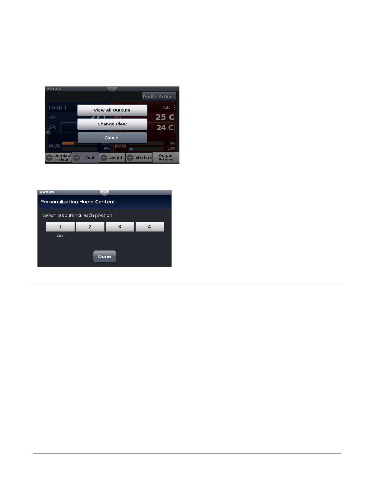
Configuring the Output Widget:
1. Push Output Actions (blue box above).
- View All Outputs, displays all connected outputs by their name (if given).
- Change View, defines widget location.
- Cancel, Returns to the Home screen.
2. Push the Change View button.
3. Push the desired position (1 to 4) and define its function.
4. Push the Done button when complete.
Data Logging
Note: To view a video about Data Logging go to w w w.watlo w.c o m/F4T.
Data Logging can be enabled at any time and will log a user selectable list of data points.
While data logging is enabled, the data log file is stored within either the USB device memory
or internal memory. Once the file reaches a specified size (if being transferred automatically),
it will be sent directly to one of three other destinations (USB, TFTP server or a Samba server). The file transfer can also be initiated manually at any time. The file transfer process from
internal memory, whether completed automatically or manually, will move all log files from
internal memory to the selected destination. To learn more about data logging see "Data
Logging" in the Overview Section of this User Guide.
From the UI, there are two ways to setup and initiate data logging:
To setup and run data logging using the UI:
①
1. Press the Menu button.
2. Press the Data Logging button.
3. Press the Select Data Points button to select the data points to be captured in the log.
4. Press the Done button when complete.
Watlow F4T • 55 • Chapter 3 Using the F4T Front Panel
Page 59

5. Push the Setup button to define the following:
- Logging Status: indicates whether or not recording is active or not.
- File Name: any alphanumeric characters, 63 maximum.
Note:
A new dedicated file is created when data logging starts and the filename format
will be "file name" "date stamp" "time stamp".csv or enc".
- Log To: USB or Internal Memory.
- Log Interval: defines the frequency in which the log will be written, 0.1 second to 60
minutes.
- File Type: Encrypted (*.enc), Comma Separated Values (*.csv) or Both.
- File Size Limit: 20MB when using TFTP or Samba, 1GB when using USB.
- Memory Full Action: when log to device defined above is full, Overwrite or Stop.
Note:
Logging to USB allows for Stop only, when memory is full.
- Date Format: MM/DD/YYYY or DD/MM/YYYY.
- Time Format: 12 or 24 hour clock.
6. Push the Done button when complete.
Note:
Although this completes the setup it may be desired to configure the file transfer
function before starting data logging (see Transferring Data Log Files on page 64).
7. If desired push the Annotation button. Annotation allows for time specific entry of up
to 32 alphanumeric characters to a specific entry (line) within the log file. The maximum speed at which annotation can be written to the log file is approximately once every 20 seconds. Once written to the file, the annotation field on the UI will be deleted
where a new value can be entered and written again.
8. Push the Start button to begin data logging.
Note:
Data logging is terminated when power is lost, however, the file as it was prior to the loss
of power will be retained.
② To enable data logging when running a profile: 5
[J, K, L or M], while the 7th digit must be [D, E or F].
1. From the Home screen push Profile Actions button.
2. Push Go to Profiles button.
3. Push the Actions button of the desired profile.
4. Push the View/Edit Details.
3. Push the Log Data button to indicate "Yes".
Note:
If data logging is already running when the profile starts with data logging enabled, the
data log filename will remain as stated in the note above with the profile log data concatenated to the currently running data log file. If data logging is not running, a new dedicated data log file is created when the profile starts and ends when the profile stops. The
filename format will be "Profile name" "date stamp" "time stamp".csv".
th
character of the part number must be
Watlow F4T • 56 • Chapter 3 Using the F4T Front Panel
Page 60

Batch Processing Programming - Batch Menu
1
2
3
Home Screen
Main Menu
Batch Menu
Batch Processing Programming - 4 Simple "How To" Programming Steps
Step 1
Set up
Admin. or Manager
Line Operator
1
1. Create Part and Profile list - Profiles automatically run
based on parts being scanned in by operator
2. Set up Load Batch and Unload Batch fields the end user
will be prompted to scan for the job
Daily Operations
3. Batch Entry - Load: Operator will scan in bar code fields
being requested by controller
4. Batch Entry - Unload: Operator will scan in bar code fields
being requested by controller
2
Test 1 = Profile 1
Test 2 = Profile 2
3
4
User bar code scanner to enter
desired part(s)
2 bar codes were scanned in
Click Done when finished
7
Verify part to profile list is correct
Watlow F4T • 57 • Chapter 3 Using the F4T Front Panel
5
View entire part to profile
entry list for accuracy
8
Page 61

Batch Processing Programming - 4 Simple "How To" Programming Steps (con't)
Step 2
Set up
Admin. or Manager
Line Operator
1. Create Part and Profile list
2. Set up Load Batch and Unload Batch fields the end user
will be prompted to scan for the job
Daily Operations
3. Batch Entry - Load: Operator will scan in bar code fields
being requested by controller
4. Batch Entry - Unload: Operator will scan in bar code fields
being requested by controller
1
4
7
2
Create Load Batch bar code fields
the operator will be asked to scan
5
8
3
Edit name
6
9
Edit field or list
10
Repeat steps 2-10 to set up
Unload Batch bar code fields
Up to 25 different custom named fields can be added
Watlow F4T • 58 • Chapter 3 Using the F4T Front Panel
11
Set up of batch processing complete
Page 62

Batch Processing Programming - 4 Simple "How To" Programming Steps (con't)
Step 3
Set up
Admin. or Manager
Line Operator
1. Create Part and Profile list
2. Set up Load Batch and Unload Batch fields the end user
will be prompted to scan for the job
Daily Operations
3. Batch Entry - Load: Operator will scan in bar code fields
being requested by controller
4. Batch Entry - Unload: Operator will scan in bar code fields
being requested by controller
1
Appears if any part scanned is not
included within the
“Part to Profile List”
5
2
Using bar code scanner add part
entries. Can also manually type in
part entries by pressing green box
and using pop-up keyboard
Appears if any new additional part
scanned is not in correct profile
“Part to Profile List”
6
3
4
7
Part entry automatically set “Test 1” profile
Continue scanning remaining fields as green
Box will advance with each scanned single
entry
8
Batch Entry - Load completed
Watlow F4T Controller • 59 • Chapter 3 Using the F4T Front Panel
“Test 1” Profile and data logging
both start automatically
9
Review for accuracy
Page 63

Batch Processing Programming - 4 Simple "How To" Programming Steps (con't)
Step 4
Set up
Admin. or Manager
Line Operator
1. Create Part and Profile list
2. Set up Load Batch and Unload Batch fields the end user
will be prompted to scan for the job
Daily Operations
3. Batch Entry - Load: Operator will scan in bar code fields
being requested by controller
4. Batch Entry - Unload: Operator will scan in bar code fields
being requested by controller
1
“Test 1” Profile running
3
2
When profile completes F4T/D4T
transitions from showing home
screen to showing post batch
entry screen
4
User (Kirk) scanned in their ID as
the unloading operator
5
Scan requested data
A) If user presses home key and exits without completing task then
Batch Mode Menu will show “Unload Batch” icon and data logging is still
running
B) If operator scans “Unload Operator” bar code the controller will advance to screen 5
When user selects “Complete” confirming that all unload
6
batch fields have been entered the F4T/D4T automatically
returns back to home screen
Batch report data log file
will now be automatically
generated by F4T/D4T
controller.
Watlow F4T • 60 • Chapter 3 Using the F4T Front Panel
Page 64

Export Data Log Report via USB Stick
Use existing "File Transfer" method to export data log file now formatted as a Batch Report
(configuration, profiles, data log)
Scenario described below: Export via USB stick plugged into F4T/D4T controller.
1
4
Transfer file on USB stick into a
PC to view file
2
3
5
Microsoft Excel view of Batch Report (.CSV file format)
“Batch” Bar code data
Thermal Data
Creating and viewing encrypted data files are also available.
Details covered in Watow F4T videos available on line.
Want to learn more:
• Data logging video: https://www.youtub e.com/watch?v=Q C-dnzoKEXQ&t=0s&index=2&list= PLa
QlQSMB2FG3K7m-mnhLubeh9W6bJcBZJ
• Data log/batch report file transfer video: https://w ww.youtu be.com/watch?v=Sg _eoNXQcus&i
ndex=3&list=PLaQlQSMB2FG3K7m-mnhLubeh9W6bJcBZJ
Watlow F4T Controller • 61 • Chapter 3 Using the F4T Front Panel
Page 65

Adding a Part Profile List using a PC
Alternative to creating part-profile list via USB scanner
Can use readily available PC software for large part list entry
into controllers
1 2
Test 1 = Profile 1
Test 2 = Profile 2
3
User bar code scanner to enter
desired part(s)
4
1. Export the “Part-Profile List” file from the F4T onto a USB thumb drive
2. With USB stick plugged into PC, open ProfileToPart.json file on a PC using WordPad progr am
(not Notepad)
3. Copy and paste sample data from WordPad into Excel
2
3
Profile 1 = Test 1
Part 1 = 0004-0329-0000
Part 2 = 0004-0240-0000
Watlow F4T • 62 • Chapter 3 Using the F4T Front Panel
Page 66

Adding "Part-Profile List" using a PC (con't)
4. Use Excel to enter additional part numbers
a) Add more part numbers (column C)
b) Add extra format type data for the json such as “ [ } , type format data
(columns A, B, D, E)
c) Use concat function to merge columns A-E together
d) Copy and past new part numbers back into WordPad program
5. Copy the Excel data and paste unformatted text back into WordPad file
Syntax rules:
• Use “ , ” format between each part number
• Use [ at the start and ] at the end of each profile part number list
• Use { at the start and } at the end of each complete list
Watlow F4T Controller • 63 • Chapter 3 Using the F4T Front Panel
Page 67

Adding "Part-Profile List" using a PC (con't)
6. Save the WordPad file to a USB thumb drive
7. Import "Part-Profile List" file back into the F4T and verify list of parts listed to each profile
F4T with the USB Mouse Feature
Watlow F4T • 64 • Chapter 3 Using the F4T Front Panel
Page 68

Transferring Data Log Files via the UI
A user can transfer data log files manually or automatically.
Note:
All closed data log files are transferred. If a file is open during the logging process,
that file will not transfer until closed.
To transfer files manually:
1. Push the Menu button.
2. Push the File Transfer button.
Note:
The graphic above may or may not look similar when viewed on your F4T. To appear as
shown, a USB thumb drive must be installed and both a TFTP and Samba server must be
configured.
3. Push the Export button for the desired destination.
To transfer files automatically:
1. Push the Menu button.
2. Push the Data Logging button.
3. Push the Data Log File Transfer button.
4. Select Auto Transfer Type, TFTP, Samba or USB.
If TFTP or Samba is selected above, the server must be configured. For instructions on how
to configure either or both, click on the server of choice: TFTP or Samba
Flashing the Controller Firmware
On occasion, the F4T firmware may be updated. When flashing the firmware ensure that
power to the controller is not disrupted and allow the process to proceed to completion. Once
the process is complete, the controller will come back up with the same configuration (in its
entirety) prior to flashing.
To flash the controller to the latest firmware version:
1. Copy the file "F4TUpdate" to the root directory of a USB thumb drive.
2. Insert the USB thumb drive into either of the USB ports on the back of the F4T.
Watlow F4T Controller • 65 • Chapter 3 Using the F4T Front Panel
Page 69

Note:
Prior to initiating this process ensure that there is only one thumb drive connected.
3. Push the Menu button.
4. Push the Settings button.
5. Push the Update button.
6. Push the Install Update button.
Note:
After executing step 6 above, the three screen shots below will appear on screen as the
flashing activity proceeds.
Copy files:
File Update:
File Update Complete:
When this last screen appears, it will remain on screen for approximately 15 seconds.
Note:
The controller will be restored to reflect the same state it was in when the flashing
activity was started. For example, if the controller was in auto mode it will be returned
to auto mode.
Watlow F4T • 66 • Chapter 3 Using the F4T Front Panel
Page 70

Email and Text Alerts
The Email/Text Alert feature provides a method to send an Email and/or an Email-to-SMS message
(text message) to defined contacts when specified events occurr. Up to 10 unique alerts can be configured. 10 Contacts can be predefined to receive alerts (with 2 addresses available per Contact).
When the specified conditions occur for any enabled Alert, the F4T will automatically send an Alert
message to each Recipient that has been selected within the respective Alert.
An Email or Text alert informs the recipient that an event has occurred for which they can be reactive or proactive in their response to the application. For example, a notification may be desired
when a profile step has completed to allow the contact to begin preparing material for a future step
in the process.
Alerts can be configured for:
• Select profile conditions for Any profile or an Individual profile, including: Profile Started/Paused/
Resumed/Ended, Profile Event Outputs becoming Active or Any/Individual Step Ends
• Alarm conditions
• Limit conditions
• When an analog input error has occurred
Note: The F4T controller is only capable of sending Alerts when the following conditions are met:
• The F4T is properly connected to a network via Ethernet
• The Email Server Settings are configured to allow the connection to an email server
• Email/Text Enabled is set to YES (in Email Server Settings)
Note: The timing and delivery of the Email and Text alerts is dependent on a variety of components
for delivery. The failure of the internet connection, email server, power supply, or other components can prevent the delivery of the Alert. As a safety precaution, DO NOT rely on the delivery of
an Alert for an event.
From the F4T Main Menu, press the Email and Text button to access the Email and Text screen.
Watlow F4T Controller • 67 • Chapter 3 Using the F4T Front Panel
Page 71
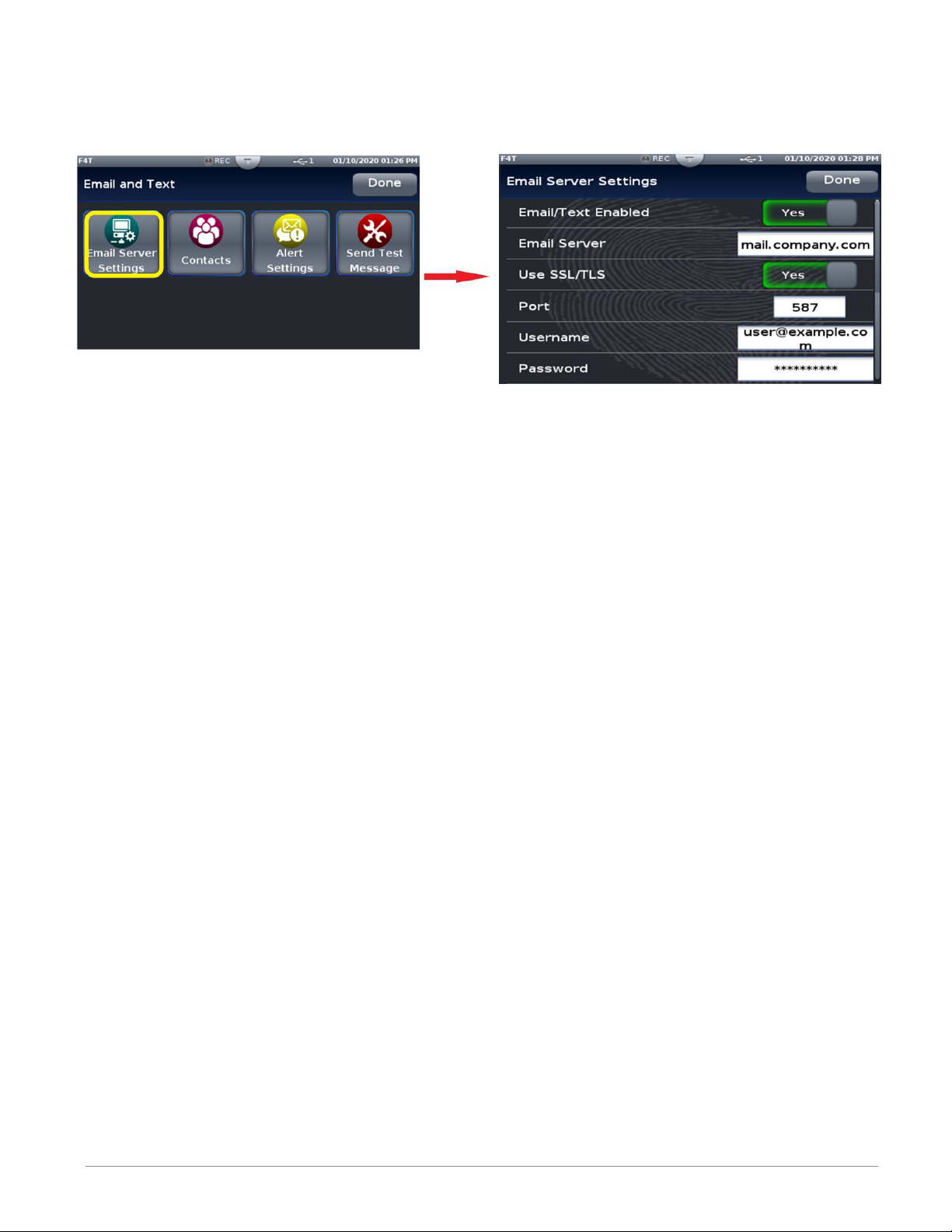
Step 1: Email Server Settings
You must enter the server settings to enable the F4T controller to send alert messages. Press
the Email Server Settings button to access the Server Settings screen.
Touch each field to edit the data for that field and enter the appropriate information. If you do
not know the correct information for your email server, contact your system administrator for assistance.
The bracketed bold settings below represent the defaults as delivered from the factory:
• Email/Text Enabled: Yes, [No] Enables the Email Text feature.
-Yes: Email/Text feature is enabled. Allows the F4T to send Alerts when the Alert conditions are met.
-No: Email/Text feature is not enabled. No Alerts will be sent.
• Email Server: [mail.company.com] Enter the name of the email server that will be used
for sending email. Typical format is: mail.company.com. This information, along with the
SSL/TLS, Port, Username & Password settings, must be configured properly, to allow the F4T
to send messages. Contact your system administrator for assistance.
• Use SSL/TLS: [Yes], No
-Yes: use Secure Socket Layer (SSL) / Transport Security Layer (TLS) functionality.
-No: SSL/TLS is not used.
• Port: [587] Enter the Port number used by the SMTP (email) server. Typically, the stan-
dard port number used would be the following:
-Port 587 when Use SSL/TLS = Yes
-Port 25 when Use SSL/TLS = No
This may be different depending on your company’s server settings. Contact your system
administrator for assistance.
• Username: [user@example.com]
-This must be a valid username that will be used to log in to your company’s email server. This will be the sender email address when alerts are sent from the F4T.
• Password: [ ]
-Enter the password, if required by your network, that corresponds to the Username entered above.
Press the Done button in the upper right corner to save the server settings and return to the
Email and Text Main screen.
Watlow F4T • 68 • Chapter 3 Using the F4T Front Panel
Page 72

Step 2: Send an Alert Test Message
Send Test Message can be used as a diagnostic feature to determine if the Email Server Settings
and network connection are configured properly to allow the F4T to send Alert messages. No
configuration of the Contacts or Alert Settings is required to use Send Test Message.
To: The Email address that the Test Message will be sent to.
Subject: Subject line of the Test Message
Message: Body of the Test Message.
Note: The email will appear as if it comes from the email account that is used for the User-
name in Email Server Settings.
Enter the appropriate information in the fields and then press the Send button. When the con-
firmation screen is shown, press the Send button to send the test message or Cancel to dismiss
without sending.
Note: The Send Test Message function will only work if the Email/Text Enabled field is set to
YES in the Email Server Settings.
Watlow F4T Controller • 69 • Chapter 3 Using the F4T Front Panel
Page 73

Step 3: Defining Contacts
Before alerts can be sent, you must define the people or contacts to which the messages will be
sent. Press the Contacts button on the main Email and Text screen to access the Contacts screen.
You can define up to 10 contacts to receive alerts. Touch a Contact line to configure a contact for
that number. The Contact Configuration screen is shown for the contact line that you selected.
Note that the Address fields contain example text to show what type of address should be entered
in the field.
Enter a name in the Name field to identify the contact. If this field is left blank, the default Contact # will be used. Enter an Email or Email-to-SMS address in the fields provided. Two address
fields can be defined for each Contact.
To send the Alert as a text message to a recipient’s phone, an Email-to-SMS address must be entered. The format of this address is specific to each recipient’s cellular service provider. Contact
the service provider for the proper format.
Some examples of formats for common cellular service providers are:
Carrier SMS gateway domain
AT&T 10-digit number@txt.att.net
Sprint 10-digit number@messaging.sprintpcs.com
U.S. Cellular 10-digit number@email.uscc.net
Verizon 10-digit number@vtext.com
When the contact information has been entered, press the Done button in the upper right corner
to save the contact information and return to the Email and Text Main screen.
Watlow F4T • 70 • Chapter 3 Using the F4T Front Panel
Page 74

Step 4: Configuring Alerts
Once the Email Server Settings and Contacts have been defined, the Alerts can be configured. Press
the Alerts Settings button on the main Email and Text screen to access the Alerts Settings screen.
Each Alert has a toggle switch on the alert definition line to turn the alert on and off. Slide the toggle switch to the desired position once the alert has been completely configured. To define an Alert,
press the Config button beside an alert number to access the configuration screen for that alert.
Press the Config button on the Recipients line to define the Recipients that will receive this Alert.
Set the toggle button to Yes next to any Contact to notify them of this Alert condition. If All Contacts is set to Yes, the Alert will be sent to All Contacts that have valid email addresses defined.
Press the Config button on the Events line to define the events that will trigger this alert to be sent.
Press the Done button to return to the Alert configuration screen.
Watlow F4T Controller • 71 • Chapter 3 Using the F4T Front Panel
Page 75

Alert Profiles Configuration
Alerts can be configured for select profile conditions for Any profile or an Individual profile, includ-
ing: Profile Started/Paused/Resumed/Ended, Profile Event Outputs becoming Active or Any/Individual
Step Ends. Press the Config button beside the Profile field on the Alert Events screen to access the
Alert Profile Settings screen.
Press the button beside the Profile field to access the Profile Type choice box. Select the type of
profile to access the appropriate screen.
Any
Individual
If a specific Individual profile is selected, press the Tap to Select box. Select a profile from the box
to access the Individual Profile configuration screen.
Watlow F4T • 72 • Chapter 3 Using the F4T Front Panel
Page 76

From either the individual or Any Alert Profile Settings screen, select the Event Out Settings or
Step Settings configuration button to access the appropriate configuration screen.
Press the Done button on the screen when the alerts have been configured to return to the
previous screen. Continue to press the done button to return to the Main screen.
Watlow F4T Controller • 73 • Chapter 3 Using the F4T Front Panel
Page 77
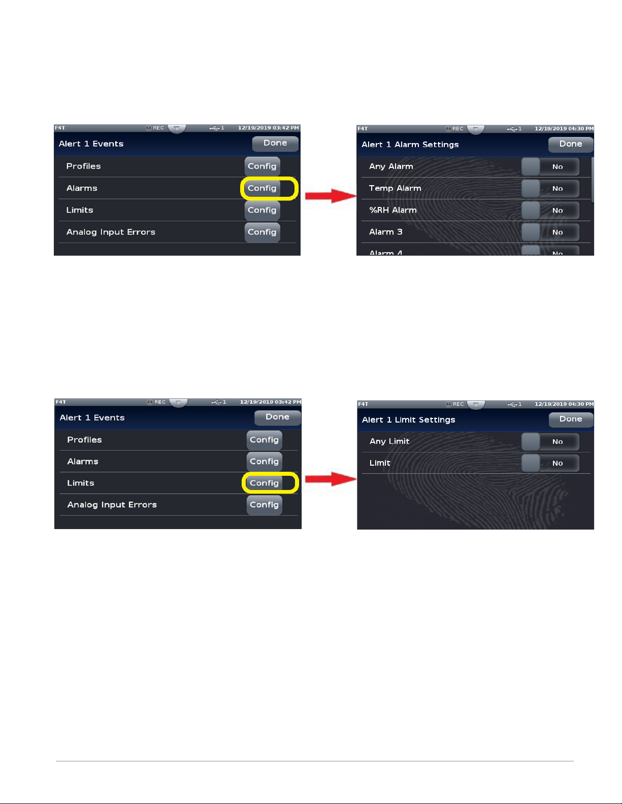
Alarm Settings Configuration
Press the Alarms Config button on the Alert Events screen to access the Alert Alarms Settings
screen. Select the appropriate settings and then press the Done button to return to the Alerts
Event screen.
Limits Settings Configuration
Press the Limits Config button on the Alert Events screen to access the Alert Limits Settings
screen. Select the appropriate settings and then press the Done button to return to the Alerts
Event screen.
Watlow F4T • 74 • Chapter 3 Using the F4T Front Panel
Page 78
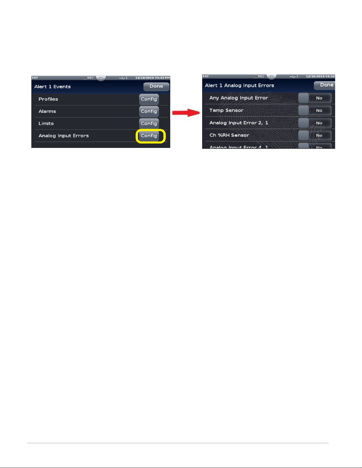
Analog Input Errors Settings Configuration
Press the Analog Input Errors Config button on the Alert Events screen to access the Alert Analog Input Errors Settings screen. Select the appropriate settings and then press the Done button to return to the Alerts Event screen.
Watlow F4T Controller • 75 • Chapter 3 Using the F4T Front Panel
Page 79
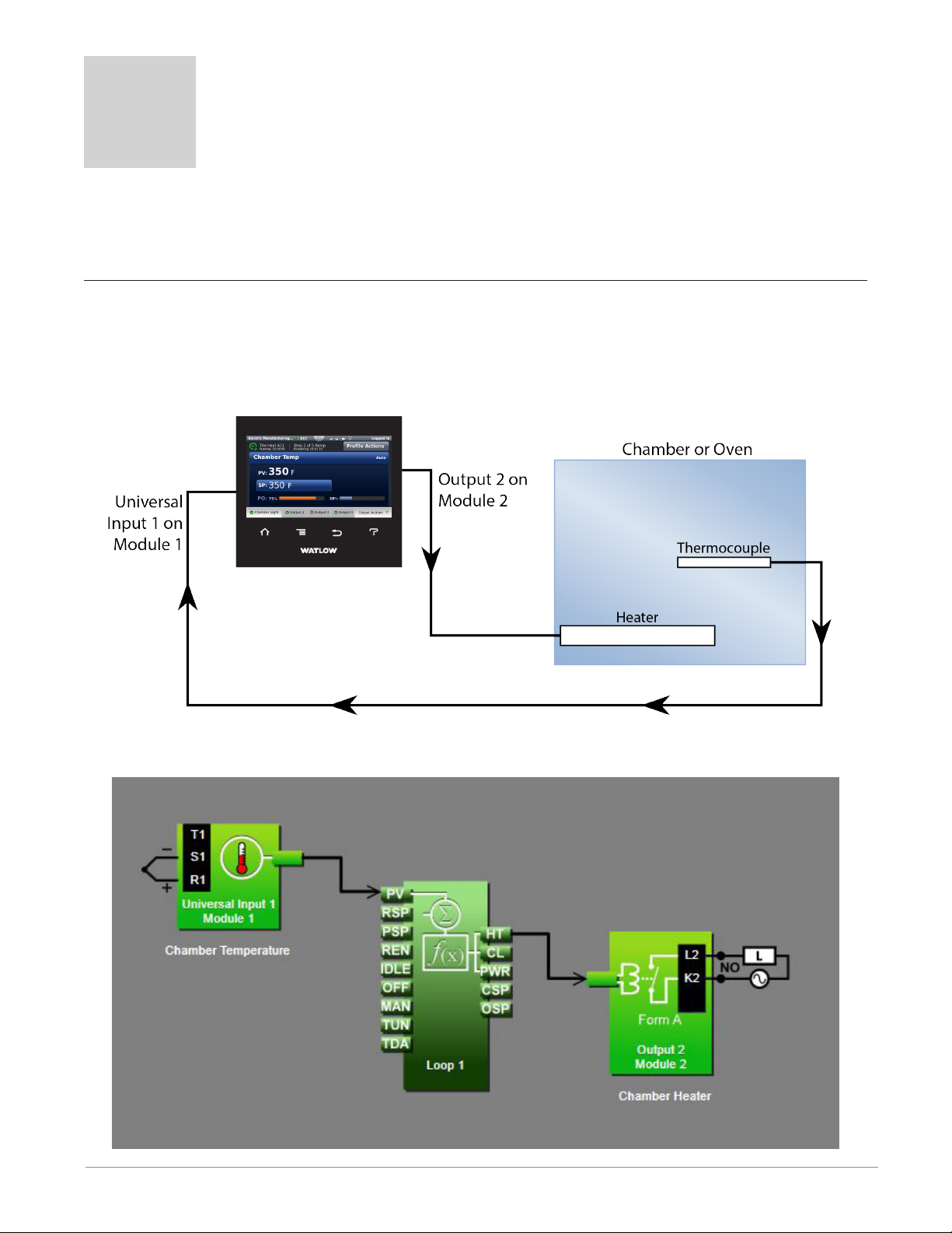
4
Chapter 4: Application Examples
Applications
This chapter contains the basic instructions for configuring sample applications. Refer to
Chapter 5 for detailed descriptions of the function blocks and parameters.
Single Loop Control
In this example, Universal Input 1 on module 1 measures the temperature of a chamber or
oven with a thermocouple. Control Loop 1 takes its feedback directly from the universal input and signals output 2 on module 2 to switch the heater that heats the chamber or oven
accordingly.
Function Block Diagram
Watlow F4T • 76 • Chapter 4 Application Examples
Page 80

Application Tips:
• Loop blocks are initially located in the library and can be dragged to the canvas.
• The signal from the universal input carries the process value to the PV receiver on the
loop block where it is used as feedback to the control algorithm.
• The signal from HT on the loop to the output block controls the heater by signaling
when the heater should be on for on-off control or how much it should be on with a 0
to 100% signal for PID control.
• Enter names for blocks where possible to make the application easier to understand.
• Make sure the input block’s Sensor Type and other parameters are set correctly for
your sensor.
• In the loop block set the Control Action and Heat Algorithm based on the type of load
being controlled.
• If you use the PID algorithm, you’ll need to tune the loop for your system. For more information on autotuning see the section entitled "Autotune" in Chapter 5.
• Depending on the type of output and the load it drives, you may be able to set Time
Base Type in the output block to Variable Time Base to improve control stability. Don’t
use this setting with mechanical relays or switching devices or loads that are not purely
resistive.
Heat and Cool Control Loop
In this example Universal Input 1 on module 1 measures the temperature of an environmental
chamber with a thermocouple. Control Loop 1 takes its feedback directly from the universal
input, and uses output 2 on module 2 to heat the chamber and output 2 on module 1 to cool
the chamber as needed.
Watlow F4T • 77 • Chapter 4 Application Examples
Page 81
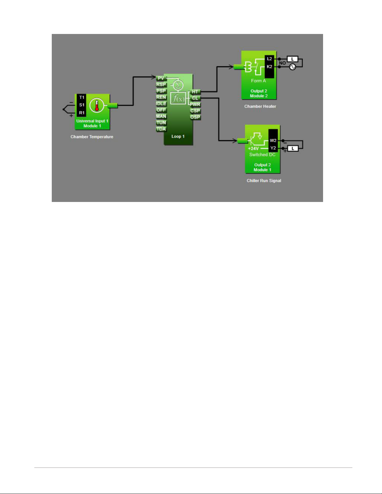
Function Block Diagram
Application Tips:
• Loop blocks are initially located in the library and can be dragged to the canvas.
• The signal from the universal input carries the process value to the PV receiver on the
loop block where it is used as feedback to the control algorithm.
• The signal from HT on the loop to the output block controls the heater by signaling
when the heater should be on for on-off control or how much it should be on with a 0
to 100% signal for PID control.
• The signal from CL on the loop to the output block controls cooling by signaling when
the chiller should be on.
• Enter names for blocks where possible to make the application easier to understand.
• Make sure the input block’s Sensor Type and other parameters are set correctly for
your sensor.
• In the loop block set the Control Action, Heat Algorithm and Cool Algorithm based on
the type of load being controlled.
• If you use the PID algorithm, you’ll need to tune the loop for your system. For more information on autotuning see the section entitled "Autotune" in Chapter 5.
• Depending on the type of outputs and the loads they drives, you may be able to set
Time Base Type in the output block to Variable Time Base to improve control stability.
Don’t use this setting with mechanical relays or switching devices or loads that are not
purely resistive.
Watlow F4T • 78 • Chapter 4 Application Examples
Page 82

Process Alarm
In this example Universal Input 1 on module 1 measures the temperature of a chamber or oven with a thermocouple. Alarm 1 monitors the temperature from the universal input which is
also used by the control loop as feedback for heat control. When the temperature goes outside the normal range defined by the user-adjustable, alarm set points, output 1 on module 4,
a form C relay energizes an audible alarm and an indicator lamp to get the operator’s attention.
Function Block Diagram
Application Tips:
• Alarm blocks are initially located in the library and can be dragged to the canvas.
• The signal from the universal input to IN on the alarm is the one the alarm monitors
against the alarm set point.
• The signal from the alarm to the output indicates when the alarm has occurred. The
alarm is indicated on the controller whether or not there is an output attached; the
output on the alarm block is for use with additional logic in the application diagram or
to drive external devices as is shown in this example.
• Enter names for blocks where possible to make the application easier to understand.
Watlow F4T • 79 • Chapter 4 Application Examples
Page 83

• The control loop is not necessary for the alarm; it is shown here just to make it clear
that more than one function block can receive the analog input signal.
• Make sure the input block’s Sensor Type and other parameters are set correctly for
your sensor.
• By default the alarm’s type setting is Off. Set it to Process Alarm.
• Set the alarm’s Sides setting to High or Low if you want to monitor only for the process value going too high or too low, or set Sides to Both if you want the alarm to occur
when the process value is either too high or too low.
• For more information on alarm parameters see the section entitled "Alarm" in Chapter
5.
Deviation Alarm
In this example Universal Input 1 on module 1 measures the temperature of a chamber or oven with a thermocouple. Alarm 1 monitors the temperature from the universal input which is
also used by the control loop as feedback for heat control. When the temperature gets farther
from set point than the user-adjustable, alarm set points, output 1 on module 4, a form C relay energizes an audible alarm and an indicator lamp to get the operator’s attention.
Function Block Diagram
Watlow F4T • 80 • Chapter 4 Application Examples
Page 84

Application Tips:
• Alarm blocks are initially located in the library and can be dragged to the canvas.
• The signal from the universal input to IN on the alarm is the one the alarm monitors
against the alarm set point.
• The signal from CSP on the loop to CTR on the alarm transmits the loop’s set point to
the alarm so that the deviation alarms can be relative to the loop’s set point.
• The signal from the alarm to the output indicates when the alarm has occurred. The
alarm is indicated on the controller whether or not there is an output attached; the
output on the alarm block is for use with additional logic in the application diagram or
to drive external devices as is shown in this example.
• Enter names for blocks where possible to make the application easier to understand.
• A deviation alarm uses the signal received at CTR as the center of the deviation band.
The high and low alarm set points are relative to that center value. In most deviation alarm applications users want the alarm deviation centered on a control loop’s set
point as shown in this example, but any analog signal could be used.
• Make sure the input block’s Sensor Type and other parameters are set correctly for
your sensor.
• By default the alarm’s type setting is Off. Set it to Deviation Alarm.
• Set the alarm’s Sides setting to High or Low if you want to monitor only for the process value going too high or too low, or set Sides to Both if you want the alarm to occur
when the process value is either too high or too low.
• For more information on alarm parameters see the section entitled "Alarm" in Chapter
5.
Watlow F4T • 81 • Chapter 4 Application Examples
Page 85

Safety Limit
In this example one thermocouple measures the temperature of the chamber or oven providing feedback to a control loop that drives a heater with its heat output. A second thermocouple connected to Temperature Input 1 on module 3 also measures the temperature but provides its signal to the limit function. The limit controls a form A relay output that is energized
when the temperature has not exceeded the safety limit setting and opens when the limit is
exceeded. The control loop’s output signal to the heater goes through the limit relay such that
power to the heater is cut off when the temperature is above the limit. Also a momentary
switch is connected to digital input 2 on module 3 so that the limit can be reset without using
the controller interface.
Function Block Diagram
Application Tips:
• Because the limit option is designed for safety, the limit block is automatically present
on the diagram, and its input and output signals cannot be changed.
• The signal from the digital input to the RST on the limit block allows a momentary
switch wired to that input to reset the limit alarm.
Watlow F4T • 82 • Chapter 4 Application Examples
Page 86

• The reset switch is optional. The limit can be reset using the controller’s user interface. Note that it is not considered good practice to locate a reset switch in a location
so remote from the equipment that the person resetting the limit cannot be sure it is
safe to do so.
• Enter names for blocks where possible to make the application easier to understand.
• Make sure the temperature input block’s Sensor Type and other parameters are set correctly for your sensor.
• By default the limit’s Sides setting is Both. Set it to High or Low if you want to monitor
only for the process value going too high or too low, or leave it set to Both if you want
the limit to trip when the process value is either too high or too low.
• Set the limit's Low Set Point and/or High Set Point to the values at which you want to
open the limit relay’s contacts.
• Set the limit's Minimum Set Point and Maximum Set Point to the values above and below
which you do not want an operator to set the limit's Low Set Point and High Set Point.
Sensor Backup
In this example there are two thermocouples measuring the temperature of an oven. Normally
one provides feedback to a control loop that drives the heater. In the event the first thermocouple fails, the controller switches automatically to the second providing uninterrupted control.
Function Block Diagram
Watlow F4T • 83 • Chapter 4 Application Examples
Page 87

Application Tips:
• Process blocks are initially located in the library and can be dragged to the canvas.
• You can connect up to four sensors to the Process block. The process block passes along
the signal from the lowest number receiver that has no error on its sensor signal.
• The signal transmitted by the process block can be used by a control loop or any other
function as if it was received directly from a universal input block.
• Make sure the input blocks’ Sensor Type settings and other parameters are set correctly
for your sensors.
• Set the Process block’s Function to Sensor Backup.
Profile Ramp and Soak
In this example the temperature of an environmental chamber is measured by a thermocouple
connected to Universal Input 1 on module 1 and controlled by a control loop with a heater
connected to output 2 on module 2. The chamber also has a door switch so the profile can
sense when the door is opened or closed and a test activation circuit to turn on parts that are
being tested at specific profile steps.
Function Block Diagram
Watlow F4T • 84 • Chapter 4 Application Examples
Page 88

Application Tips:
• The profile engine block is initially located in the library and can be dragged to the
canvas.
• The signal from the input to PV1 on the profile engine lets the profile engine monitor
the process value when guaranteed soak is used and to establish the initial set point
when starting a profile.
• The signal from SP1 on the profile engine to PSP on the control loop allows the profile
engine to control the loop’s set point.
• If you want to be able to have a profile wait for a specific process value, connect the
process value signal to the EVT1 receiver (left side of the profile engine).
• The door switch signal to EVT2 on the profile engine allows profiles to be programmed
to wait for the door to be open or closed.
• The signal from the EVT1 transmitter (right side of the profile engine) to the test activation output allows the profile to enable an external circuit to power the parts under
test at the appropriate times.
• Enter names for blocks where possible to make the application easier to understand.
Cascade Control
In this example a part is heated in an oven. The part takes a lot longer to heat up than the
heater and oven, and it can be damaged if heated so quickly that the temperature on the surface is a lot higher than the interior temperature. To heat the part in the minimum amount of
time while protecting it from excessive thermal stress, two temperature sensors are used and
the controller is configured for cascade control.
Watlow F4T • 85 • Chapter 4 Application Examples
Page 89

Function Block Diagram
Application Tips:
• The cascade block is initially located in the library and can be dragged to the canvas.
• The signal from the input for the part sensor to PVO on the cascade block lets the cascade algorithm know the temperature of the part being heated and is used to determine the set point for the heater.
• The signal from the input for the heater sensor to PVI on the cascade block is the feedback for the inner loop which controls the heater temperature.
• The signal from HT on the cascade block to the output controls the heater.
• Make sure the input blocks’ Sensor Type settings and other parameters are set correctly
for your sensors.
• Set the Cascade block’s Function to Process.
• Set Range Low and Range High settings to limit the heater temperatures to which the
part can be exposed. Setting Range Low to 50 and Range High to 210 means that when
the temperature in the part is low, the heater set point will go as high as 210, but as
the temperature inside the part increases, the heater set point drops.
• In this example Control Action is set to Heat, the Inner Loop Heat Algorithm is set to
PID.
• The Inner loop PID settings were set by using the auto tune feature, but the outer loop
PID settings were set manually for proportional only control with a proportional band of
20 so that the heater set point is proportional to how cool the part is.
• If the oven must heat parts to many different temperatures or must heat parts over
a larger range of temperatures consider using the Deviation setting for the Cascade
blocks’ Function.
• For more information on cascade control parameters see the section entitled "Cascade"
in Chapter 5.
Watlow F4T • 86 • Chapter 4 Application Examples
Page 90
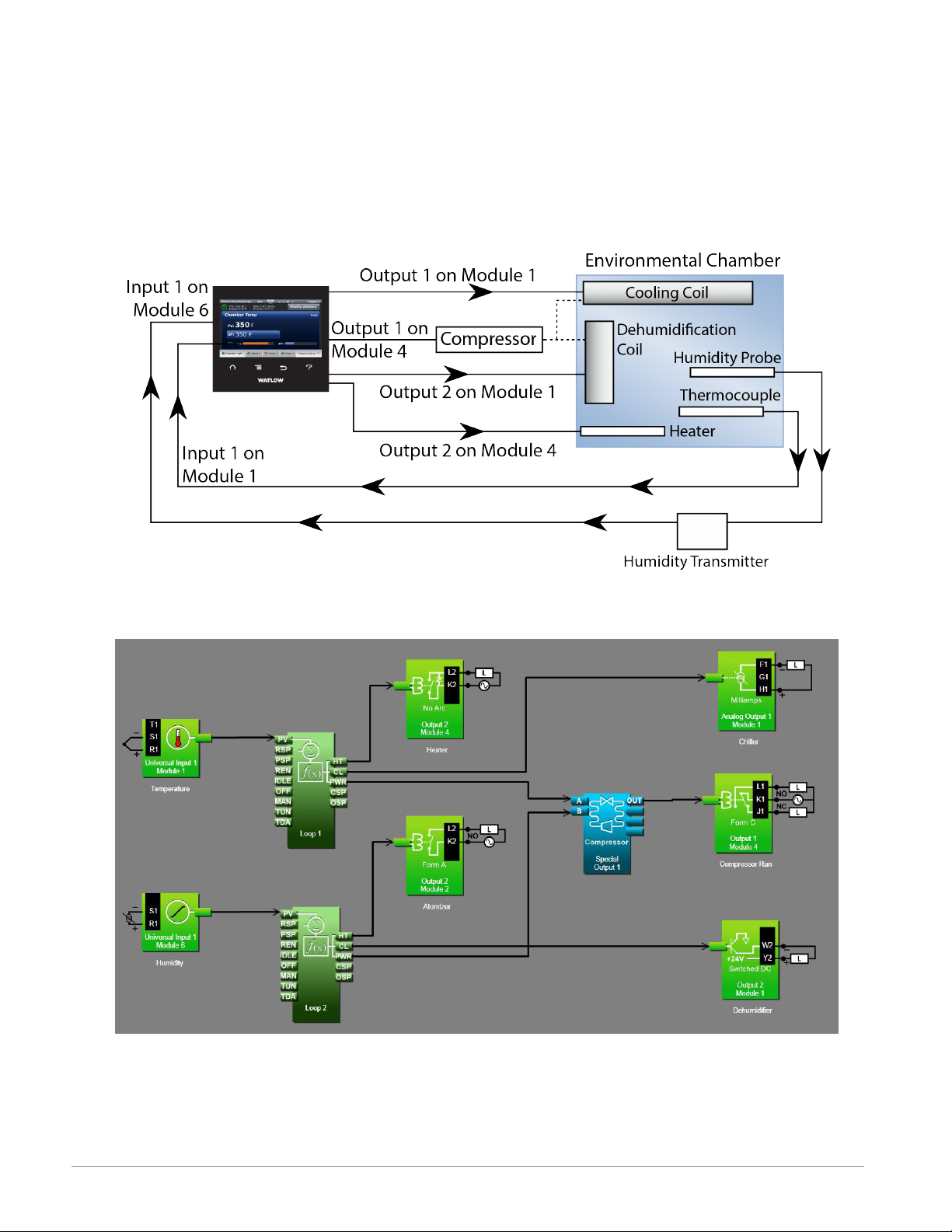
Compressor Control
In this example the temperature and humidity of an environmental chamber are controlled by
two loops. Loop 1 uses a heater to increase the temperature and a cooling coil to lower the
temperature. Loop 2 uses a solenoid to control water flow to an atomizer to raise the humidity and a dehumidification coil to lower the humidity. The cooling and dehumidification coils
share a compressor. To minimize wear on the compressor and use of electricity, the compressor is turned off and on by the controller’s Special Output function block configured for compressor control.
Function Block Diagram
Watlow F4T • 87 • Chapter 4 Application Examples
Page 91

Application Tips:
• The special output block is initially located in the library and can be dragged to the
canvas.
• The signals from the temperature and humidity loops’ PWR transmitters to A and B on
the special output block indicate the percent output power for each of the loops which
allow it to determine when the temperature and/or humidity loops need or may soon
need the compressor to be on.
• The signal from OUT on the special output block signals when to turn on the compressor.
• Enter names for blocks where possible to make the application easier to understand.
• Set the special output’s function parameter to Compressor Control.
• Set the Minimum On Time and Minimum Off Time parameters long enough to protect
the compressor from too much cycling, but short enough to allow the compressor to
turn off between uses, for example 45 seconds for minimum on time and 15 seconds for
minimum off time.
• Set Input A Turn On and Input B Turn On to the percent of power from the temperature and humidity loops at which you want the compressor to turn on so that it is ready
when the loop needs cooling or dehumidification, for example 0%.
• Set Input A Turn Off and Input B Turn Off to the percent power at which you would be
comfortable having the compressor turn off, for example 2% for temperature and 5% for
humidity.
• Note the correct settings for the parameters above depend on the specific application
hardware.
• For more information on compressor control parameters see the section entitled "Com-
pressor Control" in Chapter 5.
Watlow F4T • 88 • Chapter 4 Application Examples
Page 92

5
Chapter 5: Function Block Reference
F4T Functions Described .............................................82
Alarm ..........................................................83
Off .................................................................... 84
Process Alarm ............................................................ 84
Deviation Alarm ........................................................... 86
Analog Outputs ....................................................90
Cascade .........................................................92
Process ................................................................. 92
Deviation ................................................................ 93
Compare .......................................................107
Off .................................................................... 108
Greater Than ............................................................ 108
Less Than .............................................................. 108
Equal To ...............................................................109
Not Equal To ............................................................ 110
Greater or Equal .........................................................110
Less or Equal ...........................................................111
Control Loop .....................................................112
Counter ........................................................125
UP .................................................................... 125
Down .................................................................. 126
Current Input ....................................................128
Digital Input .....................................................130
Input Dry Contact ........................................................ 131
Input Voltage ............................................................ 131
Digital Inputs/Outputs (I/O) ...........................................131
Input Dry Contact ........................................................ 132
Output ................................................................. 132
Input Voltage ............................................................ 134
Digital Outputs ...................................................134
Solid-State Relay - Switched DC/Open Collector ................................. 134
Electromechanical and NO-ARC Relays ........................................ 136
Key ...........................................................137
Momentary ............................................................. 137
Toggle ................................................................. 137
On Pulse ............................................................... 138
Limit .........................................................138
Limit Output .....................................................140
Watlow F4T • 89 • Chapter 5 Function Reference
Page 93

5
Chapter 5: Function Block Reference
Function Block Reference (cont.)
Linearization ....................................................140
Off .................................................................... 140
Interpolated ............................................................. 141
Stepped ................................................................ 143
Logic ..........................................................147
Off .................................................................... 147
And ................................................................... 147
Nand .................................................................. 148
Equal To ...............................................................149
Not Equal To ............................................................ 150
Or ....................................................................151
Nor ...................................................................152
Latch .................................................................. 153
RS Flip Flop ............................................................. 154
Math ..........................................................155
Off .................................................................... 156
Average ................................................................157
Switch Over ............................................................. 157
Process Scale ........................................................... 158
Deviation Scale .......................................................... 160
Differential .............................................................. 161
Ratio .................................................................. 162
Add ................................................................... 162
Multiply ................................................................ 163
Absolute Difference ....................................................... 163
Minimum ............................................................... 164
Maximum ..............................................................165
Square Root ............................................................165
Sample and Hold ......................................................... 166
Pressure to Altitude ....................................................... 166
Dew Point .............................................................. 167
Profile .........................................................169
Process Value ....................................................175
Off .................................................................... 176
Sensor Backup ..........................................................176
Average ................................................................177
Crossover .............................................................. 177
Watlow F4T • 90 • Chapter 5 Function Reference
Page 94

5
Chapter 5: Function Block Reference
Function Block Reference (cont.)
Wet Bulb / Dry Bulb ......................................................178
Switch Over ............................................................. 179
Differential .............................................................. 180
Ratio .................................................................. 180
Add ................................................................... 181
Multiply ................................................................ 181
Absolute Difference ....................................................... 182
Minimum ............................................................... 182
Maximum ..............................................................183
Square Root ............................................................183
Vaisala® RH Compensation ................................................ 184
Pressure to Altitude ...................................................... 184
Special Output ...................................................187
Off .................................................................... 187
Compressor Control ...................................................... 187
Sequencer .............................................................. 190
Motorized Valve ..........................................................191
Temperature Input .................................................192
Resistance Temperature Device (RTD) 100 and 1000 Ohm ........................192
Thermocouple ........................................................... 193
Thermistor Input ..................................................195
Timer .........................................................197
Off .................................................................... 198
On Pulse ............................................................... 198
Delay .................................................................. 200
One Shot ............................................................... 201
Retentive ............................................................... 203
Universal Input ..................................................204
Millivolts/Volts ...........................................................205
Off .................................................................... 208
Thermocouple ........................................................... 208
Milliamps ............................................................... 209
Resistance Temperature Device (RTD) 100 and 1000 Ohm ........................212
1K Potentiometer ........................................................ 213
Variable ........................................................216
Analog ................................................................. 216
Digital ................................................................. 218
Watlow F4T • 91 • Chapter 5 Function Reference
Page 95
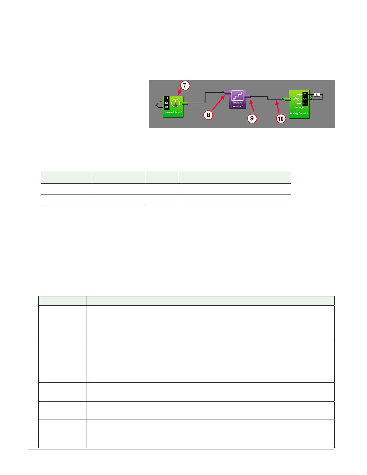
F4T Functions Described
The controller is customized by connecting function blocks (FB) as needed for the application.
A transmitter of one function is commonly connected to a receiver of another using Composer's function block diagram editor. The connections between blocks, referred to as signals,
carry information from one function block to another.
Each signal carries three pieces of information:
1. Value
• The value is either analog
(floating point numbers) or
digital (on, off, true or false).
Most function blocks expect
a specific type of value to be
received at each receiver and produce a specific type of value at each transmitter.
Depending on the context, the value of a digital signal may be thought and spoken of
in various terms. The table below lists the various terms that occur in the various contexts.
Analog Value Digital Values Logic *Active Signal Parameter Settings
0% Off False Low
100% On True High
* When the state of a digital signal that triggers an action is congurable, the values are
referred to as Active and Inactive and a parameter is provided for choosing which state
triggers the action. As an example, if the TUN receiver in the graphic above is connected
to a digital device, the Loop 1 parameter "Initiate Autotune Active Level" (High or Low)
will determine when tuning occurs.
2. Units
• An analog signal can be in units of absolute or relative temperature (Celsius or Fahrenheit), percent power or relative humidity. Values may have no units or unspecified
units, indicated as process. Digital signals have no units associated with them.
Units Description
The value is a temperature on the Celsius or Fahrenheit scale. For example,
Absolute
Tempe ratu r e
33° F as an absolute temperature is one degree above the freezing point
of water. An absolute temperature can be used as a set point or compared
with other temperatures to determine which is hotter or colder
The value is a relative number of degrees, not an absolute temperature.
Relative
Tempe ratu r e
For example, the difference between the two measured temperatures, 120°
C and 100° C is 20 degrees, but it is not the temperature 20° C. A relative
temperature is appropriate for use as a calibration offset or a deviation
alarm set point
Relative
Humidity
Power
Process
The value is a measurement of percent relative humidity (%RH)
The value is a percentage with 100% representing full power and 0% representing no power
The value is in units of measure other than degrees Fahrenheit, degrees
Celsius or relative humidity
None The value is a pure number without units
Watlow F4T • 92 • Chapter 5 Function Reference
Page 96

3. Error Status
• A signal's error status indicates whether or not the value can be relied on. A signal with
no errors (error status is none), is displayed as a black line in Composer. When something is wrong such that a function block cannot determine an appropriate value to
transmit, the signal is displayed as a yellow line in Composer. You can determine the
specific error status by mousing over the signal in the diagram. The table below lists
the possible errors that could be presented to the user. Any error status other than
none is considered an error.
Error Status Description
None No error is detected.
Open A sensor is broken or disconnected.
Shorted A sensor has failed or is shorted.
Measurement Error A measurement error has occurred.
Bad Calibration The controller has not been calibrated.
Ambient Error
RTD Error An RTD sensor error has occurred.
Fail A measurement failure has occurred.
Not Sourced
Stale Data Data sourced from another controller has become unavailable.
The ambient temperature is outside of the controller's operating
range.
The source FB is missing a required signal at one of its receivers.
Math Error A calculation has no defined result (such as divide by zero).
This chapter describes in detail each of the available functions as well as their associated parameters.
Note:
The addresses and other information required to read or set FB parameter values via a
field bus protocol is located in the "Communications" section of the Appendix to this User's Guide.
Alarm
Use an alarm to monitor an analog signal and set an output when that signal goes above or
below the user-set alarm conditions. This block is found in the Function Block Diagram edi-
tor’s Library when working with a controller that offers the Alarm block. The number of these
blocks available is shown within the parenthesis.
Use the Type parameter to set the block’s behavior. These options for Type are described in
detail in the following sections:
Off: no alarms occur. The block’s output is off.
Process Alarm: monitors an analog signal for specified alarm conditions.
Deviation Alarm: monitors an analog signal for alarm conditions relative to another signal.
Watlow F4T • 93 • Chapter 5 Function Reference
Page 97

Off
When Type is set to Off, the output is off.
Process Alarm
A Process Alarm sets its output when the receiver (IN) rises above the High Set Point or drops
below the Low Set Point. The alarm’s behavior can be customized with Logic, Latching, Blocking, Silencing and Delay Time parameters.
Signals
Direction Label Type Function
IN Analog Monitored for alarm conditions
Not used
Receivers
Transmitter - - - - Digital Indicates the alarm state (see Logic)
SIL Digital True silences the alarm (see Silencing)
CLR Digital
OFF Digital True makes the function act as if Alarm Type was set to off
True clears the alarm if the condition that caused it no longer exists (See Latching)
Name
Uniquely identify this FB using up to 20 alphanumeric characters.
Type
To monitor an analog signal for alarm conditions, set Type to Process Alarm.
Sides
Select whether the receiver (IN) is monitored for high, low or both high and low alarms.
Options:
• Both: IN is monitored for high, low or both high and low alarms.
• High: IN is monitored for a high alarm only. The low alarm is not monitored.
• Low: IN is monitored for a low alarm only. The high alarm is not monitored.
Hysteresis
Set how far the process must return into the normal range before the alarm can be cleared.
Hysteresis defines how far the signal must drop below the High Alarm Set Point before a high
alarm can be cleared and how far the signal must rise above the Low Alarm Set Point before
a low alarm can be cleared.
Range: 1 to 9,999 °F or units
2 to 5,555 °C
Watlow F4T • 94 • Chapter 5 Function Reference
Page 98

Silencing
Set whether or not the output can be returned to the non-alarm state (silenced) before the
input returns to the normal range. Silencing an alarm returns the alarm's output to its inactive
state without requiring the alarm state to be cleared. Once the alarm is silenced, the output
remains inactive until the alarm is cleared and the alarm condition reoccurs.
Options:
• Yes: alarm can be silenced by connecting a digital signal to SIL or by using the Silence
Alarm parameter
• No: alarm cannot be silenced. After an alarm occurs, the function’s output returns to
its non-alarm state only when the alarm is cleared
Latching
Select whether an alarm state is maintained (latched) or clears automatically when the process value returns to an acceptable level.
Options:
• Latching: alarm remains active until the condition that caused it no longer exists and
the alarm is reset by the CLR receiver or the Clear Alarm parameter.
• Non-latching: alarm clears automatically once the condition that caused it no longer
exists.
Blocking
Alarm blocking allows a system to warm-up after being powered up or to be adjusted without
experiencing nuisance alarms. Set alarm blocking to prevent alarms before IN has first come
within the normal operating range.
Options:
• Both: alarms are blocked when the controller powers up and deviation alarms are
blocked when the loop's Set Point or the alarm's High Set Point or Low Set Point is
changed.
• Off: alarms are not blocked.
• Set Point: deviation alarms are blocked when the loop's Set Point or the alarm's High
Set Point or Low Set Point is changed.
• Startup: alarms are blocked when the controller powers up.
Display
Provides the ability to display alarm activity to the user interface (UI).
Options:
• On: when an alarm is active will cause the controller status bar on the UI to flash yellow.
• Off: when an alarm is active there will be no indication on the UI.
Watlow F4T • 95 • Chapter 5 Function Reference
Page 99

Logic
Set which state (on or off) of the alarm function's transmitter indicates there is an alarm.
Options:
• Close on Alarm: the alarm function's transmitter is off when there is no alarm and on
when there is an alarm.
• Open on Alarm: the alarm function's transmitter is on when there is no alarm and off
when there is an alarm.
Delay Time
Set a length of time, in seconds, that an alarm condition must be present before the alarm
state and output are triggered. This setting determines the minimum time that the value at IN
must be continuously above the High Set Point or below the Low Set Point before the alarm
state and alarm function’s output indicate an alarm. If the value at IN returns within the normal range before this time, no alarm occurs. This feature can be used to minimize nuisance
alarms.
Range: 0 to 9,999 seconds
Low Set Point
Set the process value or temperature that triggers the low process alarm.
Range: -99,999 to 99,999
High Set Point
Set the process value or temperature that triggers the high process alarm.
Range: -99,999 to 99,999
Clear Alarm
Set this parameter to clear to reset the alarm state after correcting the condition that caused
the alarm.
Options: Ignore, Clear
Silence Alarm
Set this parameter to silence alarms to deactivate the output after the alarm occurs.
Options: Ignore, Silence Alarms
Deviation Alarm
A Deviation Alarm's transmitter becomes active when the receiver (IN) rises above CTR (center) by more than the High Set Point or drops below CTR by more than the Low Set Point. The
alarm conditions define a deviation window relative to CTR. CTR is typically connected to a
control loop’s set point so that when the control loop’s set point changes, the deviation alarm
window moves with it. The alarm’s behavior can be further customized with Logic, Latching,
Blocking, Silencing and Delay Time parameters.
Watlow F4T • 96 • Chapter 5 Function Reference
Page 100

Signals
Direction Label Type Function
IN Analog Monitored for alarm conditions
CTR Analog
Receivers
Transmitter - - - - Digital Indicates the alarm state (see Logic)
SIL Digital On silences the alarm (see Silencing)
CLR Digital
OFF Digital On makes the function act as if Type was set to off
Defines the center value relative to which the alarms are
evaluated (typically a control loop’s set point)
On clears the alarm if the condition that caused it no longer
exists (See Latching)
Name
Uniquely identify this FB using up to 20 alphanumeric characters.
Type
To monitor an analog signal for alarm conditions relative to another signal, set Type to Deviation Alarm.
Sides
Select whether the receiver (IN) is monitored for high, low or both high and low alarms.
Options:
• Both: IN is monitored for high, low or both high and low alarms.
• High: IN is monitored for a high alarm only. The low alarm is not monitored.
• Low: IN is monitored for a low alarm only. The high alarm is not monitored.
Hysteresis
Set how far the process must return into the normal range before the alarm can be cleared.
Hysteresis defines how far below the point at which a high alarm occurs the signal must drop
before a high alarm can be cleared and how far above the point at which a low alarm occurs
the signal must rise before a low alarm can be cleared.
Range: 1 to 9,999 °F or units
2 to 5,555 °C
Watlow F4T • 97 • Chapter 5 Function Reference
 Loading...