

Page 1
ISO 9001
EZ-ZONE® RMC (Control) Module
User’s Guide
0600-0070-0000 Rev. D Made in the U.S.A.
December 2013
Control Module
1241 Bundy Boulevard., Winona, Minnesota USA 55987
Phone: +1 (507) 454-5300, Fax: +1 (507) 452-4507 http://www.watlow.com
TOTAL
CUSTOMER
SATISFACTION
3 Year Warranty
Registered Company
Winona, Minnesota USA
Page 2
Safety Information
We use note, caution and warning symbols throughout this
book to draw your attention to important operational and safety
information.
A “NOTE” marks a short message to alert you to an important
detail.
A “CAUTION” safety alert appears with information that is
important for protecting your equipment and performance. Be
especially careful to read and follow all cautions that apply to
your application.
A “WARNING” safety alert appears with information that is
important for protecting you, others and equipment from damage. Pay very close attention to all warnings that apply to your
application.
The safety alert symbol, (an exclamation point in a triangle)
precedes a general CAUTION or WARNING statement.
The electrical hazard symbol, (a lightning bolt in a triangle)
precedes an electric shock hazard CAUTION or WARNING
safety statement. Further explanations follow:
Symbol Explanation
CAUTION – Warning or Hazard
that needs further explanation
than label on unit can provide.
Consult User's Guide for further
information.
ESD Sensitive product, use proper
grounding and handling techniques when installing or servicing product.
Unit protected by double/reinforced insulation for shock hazard
prevention.
Do not throw in trash, use proper
recycling techniques or consult
manufacturer for proper disposal.
Enclosure made of Polycarbonate
material. Use proper recycling
techniques or consult manufacturer for proper disposal.
Unit can be powered with either
alternating current (ac) voltage or
direct current (dc) voltage.
Unit is a Listed device per Underwriters Laboratories®. It has
been evaluated to United States
and Canadian requirements for
Process Control Equipment. UL
61010 and CSA C22.2 No. 61010.
File E185611 QUYX, QUYX7.
See: www.ul.com
Unit is a Listed device per Underwriters Laboratories®. It has
been evaluated to United States
and Canadian requirements for
Hazardous Locations Class 1
Division II Groups A, B, C and
D. ANSI/ISA 12.12.01-2007. File
E184390 QUZW, QUZW7. See:
www.ul.com
Unit is compliant with European
Union directives. See Declaration
of Conformity for further details
on Directives and Standards used
for Compliance.
Unit has been reviewed and approved by Factory Mutual as a
Temperature Limit Device per FM
Class 3545 standard. See: www.
fmglobal.com
Unit has been reviewed and approved by CSA International for
use as Temperature IndicatingRegulating Equipment per CSA
C22.2 No. 24. See: www.csa-inter-
national.org
Warranty
The EZ-ZONE® RMC (Control) module is manufactured by ISO
9001-registered processes and is backed by a three-year warranty to
the first purchaser for use, providing that the units have not been
misapplied. Since Watlow has no control over their use, and sometimes misuse, we cannot guarantee against failure. Watlows’ obligations hereunder, at Watlows’ option, are limited to replacement,
repair or refund of purchase price, and parts which upon examination prove to be defective within the warranty period specified. This
warranty does not apply to damage resulting from transportation,
alteration, misuse or abuse. The purchaser must use Watlow parts
to maintain all listed ratings.
Technical Assistance
If you encounter a problem with your Watlow controller, review
your configuration information to verify that your selections are
consistent with your application: inputs, outputs, alarms, limits, etc.
If the problem persists, you can get technical assistance from your
local Watlow representative (see back cover), by e-mailing your questions to wintechsupport@watlow.com or by dialing +1 (507) 494-5656
between 7 a.m. and 5 p.m., Central Standard Time (CST). Ask for
for an Applications Engineer. Please have the following information
available when calling:
• Complete model number
• All configuration information
• User’s Guide
• Factory Page
Return Material Authorization (RMA)
1. Call Watlow Customer Service, (507) 454-5300, for a Return
Material Authorization (RMA) number before returning any
item for repair. If you do not know why the product failed, contact an Application Engineer or Product Manager. All RMA’s
require:
• Ship-to address
• Bill-to address
• Contact name
• Phone number
• Method of return shipment
• Your P.O. number
• Detailed description of the problem
• Any special instructions
• Name and phone number of person returning the product.
2. Prior approval and an RMA number from the Customer Service
Department is required when returning any product for credit,
Page 3

repair or evaluation. Make sure the RMA number is on the
outside of the carton and on all paperwork returned. Ship on a
Freight Prepaid basis.
3. After we receive your return, we will examine it and try to
verify the reason for returning it.
4. In cases of manufacturing defect, we will enter a repair order,
replacement order or issue credit for material returned. In cases
of customer misuse, we will provide repair costs and request a
purchase order to proceed with the repair work.
5. To return products that are not defective, goods must be in new
condition, in the original boxes and they must be returned within 120 days of receipt. A 20 percent restocking charge is applied
for all returned stock controls and accessories.
6. If the unit cannot be repaired, you will receive a letter of explanation. and be given the option to have the unit returned to you
at your expense or to have us scrap the unit.
7. Watlow reserves the right to charge for no trouble found (NTF)
returns.
This EZ-ZONE RMC User’s Guide is copyrighted by
Watlow Electric, Inc., © December 2013 with all rights
reserved.
EZ-ZONE RM is covered by U.S. Patent No. 6,005,577
and Patents Pending
Page 4

TC
Table of Contents
Chapter 1: Overview .....................................4
A Conceptual View of the RMC Module .........................7
Getting Started Quickly ...................................... 7
Chapter 2: Install and Wire ................................13
Dimensions .............................................. 13
Power Supplies ........................................... 15
RMC Installation and Removal on a DIN Rail ....................16
Wiring .................................................. 18
Conventions Used in the Menu Pages ......................... 37
Chapter 3: Operations Pages ..............................39
Analog Input Menu ........................................ 41
Process Value Menu ....................................... 41
Digital Input/Output Menu .................................. 42
Action Menu .............................................43
Limit Menu ..............................................43
Monitor Menu ............................................ 43
Control Loop Menu ........................................ 44
Alarm Menu ............................................. 47
Current Menu ............................................48
Linearization Menu ........................................49
Compare Menu ........................................... 49
Timer Menu .............................................50
Counter Menu ............................................ 51
Logic Menu .............................................. 51
Math Menu ..............................................52
Special Output Function Menu ...............................53
Profile Status Menu ....................................... 55
Chapter 4: Setup Pages ..................................60
Analog Input Menu ........................................ 63
Process Value Menu ....................................... 66
Digital Input/Output Menu .................................. 69
Action Menu .............................................72
Limit Menu ..............................................73
Control Loop Menu ........................................ 75
Watlow EZ-ZONE® RMC Module • 1 • Table of Contents
Page 5

TC
Table of Contents (cont.)
Output Menu ............................................. 81
Alarm Menu ............................................. 84
Current Menu ............................................87
Linearization Menu ........................................88
Compare Menu ........................................... 90
Timer Menu .............................................92
Counter Menu ............................................ 94
Logic Menu .............................................. 97
Math Menu .............................................106
Special Output Function Menu ..............................110
Variable Menu ........................................... 114
Global Menu ............................................115
Profile Menu ............................................ 116
Communications Menu .................................... 123
Chapter 5: Profiling Page ................................126
How to Setup and Start a Profile ............................ 126
Chapter 6: Factory Pages ................................144
Custom Setup Menu ...................................... 145
Security Setting Menu .................................... 145
Security Setting Menu .................................... 148
Diagnostics Menu ........................................ 148
Calibration Menu ........................................149
Chapter 7: Features ....................................151
Saving and Restoring User Settings .......................... 153
Tuning the PID Parameters ................................. 153
Inputs .................................................155
Outputs ................................................ 157
Control Methods ......................................... 158
Alarms ................................................163
Resetting a Tripped Limit .................................. 164
Open Loop Detection ..................................... 165
Programming the EZ Key/s ................................. 165
Using Password Security .................................166
Modbus - Using Programmable Memory Blocks ................ 167
Watlow EZ-ZONE® RMC Module • 2 • Table of Contents
Page 6

TC
Table of Contents (cont.)
Software Configuration .................................... 169
Function Block Descriptions ................................ 172
Chapter 8: Appendix ...................................217
Troubleshooting Alarms, Errors and Control Issues .............. 217
Modbus - Programmable Memory Blocks .....................221
Control Module Specifications ..............................224
Index .................................................. 228
How to Reach Us ........................................233
Watlow EZ-ZONE® RMC Module • 3 • Table of Contents
Page 7

1
Chapter 1: Overview
Available EZ-ZONE RM System Literature and Resources
Document Title and Part Number Description
EZ-ZONE Rail Mount Access (RMA) User's Guide,
part number: 0600-0072-0000
EZ-ZONE Rail Mount Expansion (RME) User's
Guide, part number: 0600-0073-0000
EZ-ZONE Rail Mount High Density (RMH) User's
Guide, part number: 0600-0074-0000
EZ-ZONE Rail Mount Scanner (RMS) User's
Guide, part number: 0600-0071-0000
EZ-ZONE Rail Mount Limit (RML) User's Guide,
part number: 0600-0075-0000
EZ-ZONE Remote User Interface (RUI) User's
Guide, part number: 0600-0060-0000
EZ-ZONE RM Specification Sheet, part number:
WIN-EZRM-1113
Describes how to connect the RM system into an
industrial network, how to use data logging, module
backup and the real-time clock.
When additional I/O is needed the Expansion module fills the gap. This document describes common
usage and the various types of I/O available.
This module extends the density of the standard RM
modules (number of control loops and I/O points).
The User Guide describes common usage, communications and the number I/O points available.
This module adds monitoring points to the RM system. This document describes common usage and
the various types of I/O available.
This module will protect against unwanted thermal
runaway and over temperature conditions. The User
Guide describes configuration, programming and
communications capabilities.
The RUI provides a visual LED display to the RM
configuration and setup menus. This document illustrates and describes connections and also describes
the Home Page for each RM module as viewed from
the RUI.
Describes RM hardware options, features, benefits
and technical specifications.
Watlow Support Tools DVD, part number: 06010001-0000
The DVD described above ships with the product and as stated contains all of the literature above as well
as much more. If the DVD is not available one can be acquired by contacting Watlow Customer Service at
1-507-454-5300.
As an alternative to the DVD, all of the user documentation described above can also be found on the Watlow website. Click on the following link to find your document of choice: http://www.watlow.com/literature/
index.cfm. Once there, simply type in the desired part number (or name) into the search box and download
free copies. Printed versions of all user documents can also be purchased here as well.
Contains all related user documents, tutorial videos,
application notes, utility tools, etc...
Your Comments are Appreciated
In an effort to continually improve our technical literature and ensure that we are providing information that
is useful to you, we would very much appreciate your comments and suggestions. Please send any comments
you may have to the following e-mail address: TechlitComments@watlow.com
Watlow EZ-ZONE® RMC Module • 4 • Chapter 1 Overview
Page 8

Introduction
The EZ-ZONE® Rail Mount Control module (RMC)
takes the pain out of solving your thermal loop requirements whether it be for a single loop, multi-loop,
stand-alone or distributed control applications.
It just got a whole lot easier to solve the thermal
requirements of your system. The RMC module is
provided in a space-saving, rail-mount package and
is highly scalable where you only pay for what you
need. For those applications that require the ability
to configure/monitor the control over a network, Modbus RTU communications is an option. Other communications protocols are also available (e.g., EtherNet/
IP, DeviceNet, Modbus TCP and Profibus DP) when
used in conjunction with an RM Access (RMA) module or when using a Remote User Interface/ Gateway
(RUI/GTW).
Standard Features and Benefits
Integrated PID and over/under safety limit controller in one package
• Provides two mounting options (DIN rail, chassis
mount)
• Reduces wiring time and termination complexity
compared to connecting discrete products
• Reduces panel space and installation cost
• Increases user and equipment safety for over/under
temperature conditions
Integrated power controller output
• Includes the patented NO-ARC, which drives up to
15 amp resistive loads directly
• Reduces component count and cost of ownership
• Saves panel space and simplifies wiring
Current monitoring (traditional or algorithm)
• Detects heater current flow and provides alarm
indication of a failed output device or heater load
• For use in single phase loads
Communication Capabilities
• Supports network connectivity to a PC or PLC
• Watlow Standard Bus or Modbus® RTU
• Provides plug and play capabilities with Remote
User Interface (RUI’s) and RMA module
• Free standard bus communications port and free
PC software (EZ-ZONE Configurator)
Additional Control Integration Options
• Provides a sequencer function
• Includes programmable timer functions
• Includes programmable counter functions
• Allows for simple math and logic programming op-
tions
Advanced PID Control Algorithm
• Offers TRU-TUNE®+ adaptive control to provide
tighter control for demanding applications
• Provides auto-tune for fast, efficient startup
Integrated Thermal Loop Diagnostics
• Users can easily tell that the entire thermal system is functioning properly
• Provides complete system diagnostics that are far
superior to simple discrete level diagnostics
• Allows for flexible synergistic use of hardware,
such as using one loop's sensor as a backup to another loop in the event of sensor failure.
• Helps prevent load loss or allow for maintenance to
be scheduled when more convenient.
• Provides notification of system problems to help
reduce maintenance and service costs
Off-the-Shelf Designed System Solution
• Improves system reliability with a factory integrated solution that minimizes inter-module connections and potential problems at screw termination
points.
• Reduces installation cost
• Eliminates compatibility headaches often encountered with using many different components and
brands
Controller Handles High Ambient Temperatures
• Operates in an unprecedented temperature range
of -18 to 65°C (0 to 149°F) for cabinets and panel
enclosures with elevated temperature levels
Memory for Saving and Restoring User-Defined
Parameter Default Settings
• Allows customers to save and restore their own defined defaults for machine parameter settings
• Reduces service calls and downtime due to inadvertent end user parameter adjustments
RMC Modules Allow for Greater Design Flex-
ibility
• Allows PID loops to be added in increments of one.
• Saves money because you do not pay for any more
than you need and don’t settle for any less functionality than you need
Synergistic Module Control (SMC)
• Allows outputs selected for control (heat/cool),
alarms or events to be located in any physical module, regardless of which module is connected to the
input sensor
Watlow EZ-ZONE® RMC Module • 5 • Chapter 1 Overview
Page 9

Split-Rail Control (SRC)
• Allows modules to be mounted together or mounted remotely from one another (maximum distance
200 feet or 61 meters)
• Shares control operation via Synergistic Module
Control (SMC) capability
• Allows individual modules to be mounted closer
to the physical input and output devices to which
they are wired
• Improves system reliability and lowers wiring
costs
Factory Mutual (FM) Approved Safety Limit
• Increases user and equipment safety for over/under
temperature conditions
• Supports SEMI S2 specification
Agency Approvals: UL® listed, CE, RoHS,
W.E.E.E. FM, SEMI F47-0200, Class 1 Div. 2 Rating on Selected Models
• Assures prompt product acceptance
• Reduces panel builder's documentation and agency
costs
Removable Connectors
• Assures reliable wiring and reduces service calls
• Simplifies installation
Profile Capability
• Allows ramp/soak programming
• Provides 25 profiles and 400 total steps
Remote Set Point Operation
• Supports efficient set point manipulation from a
remote device such as a master control or PLC
• Allows one or more loops to be programmed to control based on another loop's set point eliminating
the cost of purchasing additional retransmit and
remote set point hardware
Retransmit
• Supports industry needs for process recording
Three-Year Warranty
• Demonstrates Watlow’s reliability and product support
Watlow EZ-ZONE® RMC Module • 6 • Chapter 1 Overview
Page 10
A Conceptual View of the RMC Module
The flexibility of the RMC software and hardware allows a large range of configurations. Acquiring a better understanding of the controller’s overall functionality and capabilities while at the same time planning out how the controller can be used will deliver
maximum effectiveness in your application.
The RMC can be connected at the system level to
as many as 17 modules, one of which can be an Access module and the others (16 maximum) can be any
combination of available modules. The user will define each address via the button on the face of each
module. Each installed RMC module must have a
unique Standard Bus address ranging from 1-9, A-F,
where the factory defaults for each is Standard Bus
address 1.
• 1 to 12 outputs (various types)
• Modbus RTU communications
As can be seen above the RMC module is fully scalable with regards to power requirements, number of
loops, inputs, and outputs.
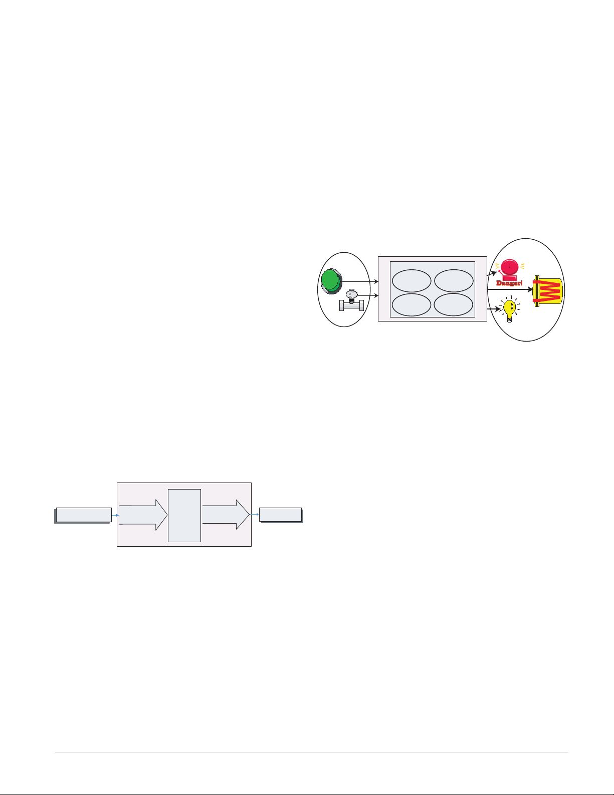
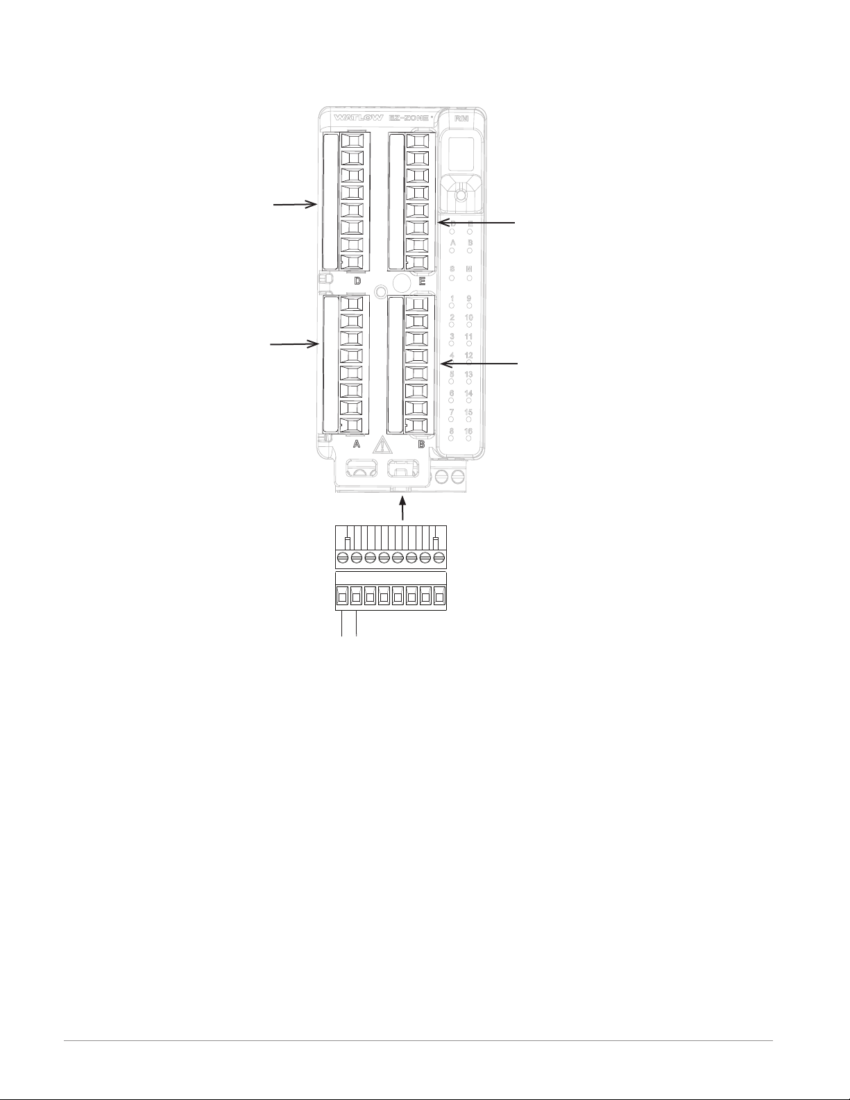
It is useful to think of the controller in three
parts: inputs, functions and outputs. Information
flows from an input to a function to an output when
the controller is properly configured. An RMC module can carry out several functions at the same time,
e.g., PID control, monitoring for several different
alarm situations, monitoring and acting upon Digital Inputs and driving output devices such as heaters, audible alarms, lights. Each process needs to
be thought out carefully and the controller’s inputs,
functions and outputs set up properly.
Getting Started Quickly
The RMC (Controller) can be ordered with up to
four PID loops with default loop configurations (all
loops) out of the box as follows:
• Analog Input functions set to thermocouple, type
J
Inputs
Functions
PID
Heat
Power
Silence
Alarms
Process
Alarm
High
Sequencing
Outputs
Outputs
• Control loops 1-4 use Analog Inputs 1-4
• Heat algorithm set for PID, Cool set to off
• Outputs set to off
• Control mode set to Auto
• Set point set to 75 °F
To enable a loop for heat simply follow the steps below:
1. Navigate to the Setup Page
2. Once on the Setup Page navigate to the Output
Menu and then the output of choice
3. Change the default setting of Off to Heat Power
4. Select the desired loop instance
Functions
Functions use input signals to calculate a value. A
function may be as simple as reading a digital input
to set a state to true or false, or reading a temperature to set an alarm state to on or off. Alternatively,
if a failure with the primary sensing device should
occur, sensor backup could be utilized to avoid an unwanted shutdown.
To set up a function, one of the first things that
must be considered is the function source and in-
Input
Function
Input Sensor
EZ-ZONE RMC Default Configuration
PID
Analog Input 1
Thermocouple Type J
Controller
Heat
Slot A
Loop 1
Output 1
Off
Output
Function
Heat
stance. For example, if the control is equipped with
Digital Inputs (source) and it was decided to use DI 9
(instance) it can then be associated with an Action to
reset an individual alarm or all alarms. To configure
as such, follow the steps below:
Setup Page (Digital I/O Menu)
Note:
Zones can communicate with one another over the
backplane (local and split rail). Once the system is
configured and running, changing zone addresses
without careful deliberation may cause disruption in
operation.
Some of the user selectable ordering options are
listed below:
1. Class 2 or SELV (Safety Extra Low Voltage) equiv-
alent Power Supplies:
• 90-264 Vac to 24Vdc @ 31 watts
• 90-264 Vac to 24Vdc @ 60 watts
• 90-264 Vac to 24Vdc @ 91 watts
2. RMC Module can provide:
• 1 to 4 control loops, limits or CT inputs
• 1 to 9 inputs (various types)
1. Navigate to the Setup Page and then to the Digital
I/O menu.
2. Select the desired instance and set the direction to
input voltage or input dry contact.
Setup Page (Action Menu)
3. Navigate to the Setup Page and then the Action
menu.
4. Set the Action Function to Alarm
5. Select which alarm instance will be reset (0 equals
all)
6. Select the Source Function to Digital I/O
7. Select the Source Instance (step 2 above)
8. Select the Source Zone (0 equals the module being
configured).
9. Select the Active Level to execute the desired function.
Watlow EZ-ZONE® RMC Module • 7 • Chapter 1 Overview
Page 11

This configuration is now complete. When the selected digital input is active the alarm or all alarms that
are latched without a currently existing alarm condition will be reset. If a specific alarm instance (1 - 8)
is selected (step 5) it will be that instance alone that
will be reset.
Note:
Alarms will reset automatically when the condition
that caused the alarm goes back to a non-alarm state
if the alarm latching prompt is set to non-latching
(Setup Page, Alarm Menu).
ue is greater than the alarm high set point, the realworld output will be driven on.
Analog
Input
Function
Control
Function
Alarm
Function
Logic
Function
Output
Function
Output
Function
Keep in mind that a function is a user-programmed
internal process that does not execute any action outside of the controller. To have any effect outside of the
controller, an output must be configured to respond
to a function.
Inputs
The inputs provide the information that any given
programmed function can act upon. In a simple form,
this information may come from an operator pushing a button, or as part of a more complex function it
may represent a remote set point being received from
another zone.
Each analog input can be configured for thermistors, thermocouples, or RTDs to read the process
variable. It can also read mV/volts, current or resistance, enabling usage of various devices to read humidity, air pressure, operator inputs and other values. The settings in the Analog Input Menu (Setup
Page) for each analog input must be configured to
match the device connected to that input.
Each digital input reads whether a device is active or inactive. A RM system can be equipped with
multiple digital I/O. Each I/O point must be configured to function as either an input or output with the
direction parameter in the digital I/O Menu (Setup
Page).
Another concept that needs to be understood is
the difference between an input tied to a real-world
device such as a thermocouple and one that is tied to
an internal function.
Analog
Input
Function
Control
Function
Output
Function
Outputs
Outputs can perform various functions or actions in
response to information provided by a function such
as: heat power from the output of the control, using a
digital output to serve as a profile event, drive a light
on or off, unlocking a door or turning on a buzzer.
Assign an output to a function in the Output
Menu or Digital I/O Menu. Then select which instance of that function will drive the selected output.
For example, you might assign an output to respond
to an internal output of a compare function or to retransmit the value of analog input 2 (instance 2).
You can assign more than one output to respond
to a single instance of a function. For example, alarm
2 could be used to trigger a light connected to output
1 and a siren connected to digital output 5.
Input Events and Output Events
Input and output events are internal states that are
used exclusively by profiles. The source of an event
input can come from a real-world digital input or an
output from another function. Likewise, event outputs may control a physical output such as an output
function block or be used as an input to another function.
Actions
Based on a given input (Digital I/O, Event output,
Logic function, etc..) the Action function can cause
other functions to occur. To name a few, starting
and stopping a profile, silencing alarms, turn control
loops off and placing alarms in non-alarm state.
In the example above the analog input function on
the left is tied directly to the control function where
its internal output is routed to a real-world output.
With a slight modification of the graphic above the
example below now ties the real-world inputs directly
to the control and alarm functions. For the sake of
this example the following is true:
- Two unique high process alarms are configured for
analog inputs 1 and 2
- The logic block is configured as an OR function
- The output function is tied to the internal output of
the logical OR function
When either process alarm is true (analog input val-
Watlow EZ-ZONE® RMC Module • 8 • Chapter 1 Overview
Page 12
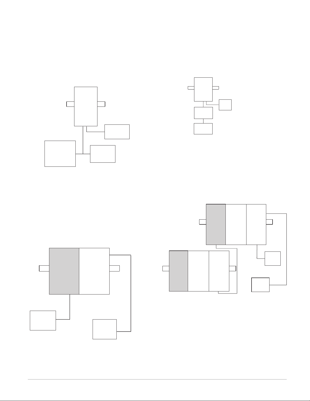
A Conceptual View of RM Hardware Configurations
Due to the scalability and flexibility in the RM system a user has several options available in the way
that the hardware can be connected. Listed below
are a few examples.
RMC Module Connected to a Remote User Interface (RUI) and a PC
In this configuration the RUI and PC are connected to the RMC module via Watlow's Standard Bus
where both will be able to talk directly to the RMC
RMC Module Connected to an Operator Interface Terminal (OIT) through an RUI/Gateway
In this configuration the OIT can be running any of
a number of protocols communicating to the RM system through Watlow's RUI/Gateway. Available protocols for the RUI/Gateway follow:
1. EtherNet/IP and or Modbus TCP
2. DeviceNet
3. Modbus RTU
RM
Control
RM
Control
Slot C
Power
Supply
PC
EZ-ZONE
Configurator
RUI
module. The PC running EZ-ZONE Configurator
software and the RUI can be used to configure and
then monitor the RMC module.
RMC Module Connected to a Programmable
Logic Controller (PLC) on a DIN Rail
In this configuration the PLC can be connected to
the RMC module via the Access module using one or
more available protocols:
1. EtherNet/IP and or Modbus TCP
2. DeviceNet
3. Modbus RTU
Slot C
RUI
Gateway
OIT
Powe r
Supply
RM System Connected to a Split Rail with OIT
In this configuration both the Inter-module Bus
(backplane communications) and Standard Bus are
connected between rails to allow for remote capabilities. It is recommended that the split rail connection
not exceed 200 feet. In this configuration the OIT
can communicate with all modules (maximum 16
modules any combination with one Access module).
Slot E
RM
Control
Slot C
RM
Expansion
Slot C
RM
Access
Slot C
Powe r
Supply
OIT
RM
Control
RM
Access
Slot CSlot C
Slot E
RM
Control
Slot C
RM
Expansion
Slot C
RM
Expansion
Slot C
Power
Supply
PLC
Watlow EZ-ZONE® RMC Module • 9 • Chapter 1 Overview
Page 13
RM Control Module Connected to an OIT Running Modbus RTU
In this configuration the control module connected
to the OIT is equipped with the Modbus RTU protocol (RMCxxxxxxxxx1xx). It is important to note that
Modbus communications takes place between the
OIT and the control it is connected to. The RM backplane is always using the Standard Bus protocol. If
it is desired that the OIT communicate to both control modules, both control modules would need Modbus communications and then pins CC, CA, and CB
would need to be daisy chained together.
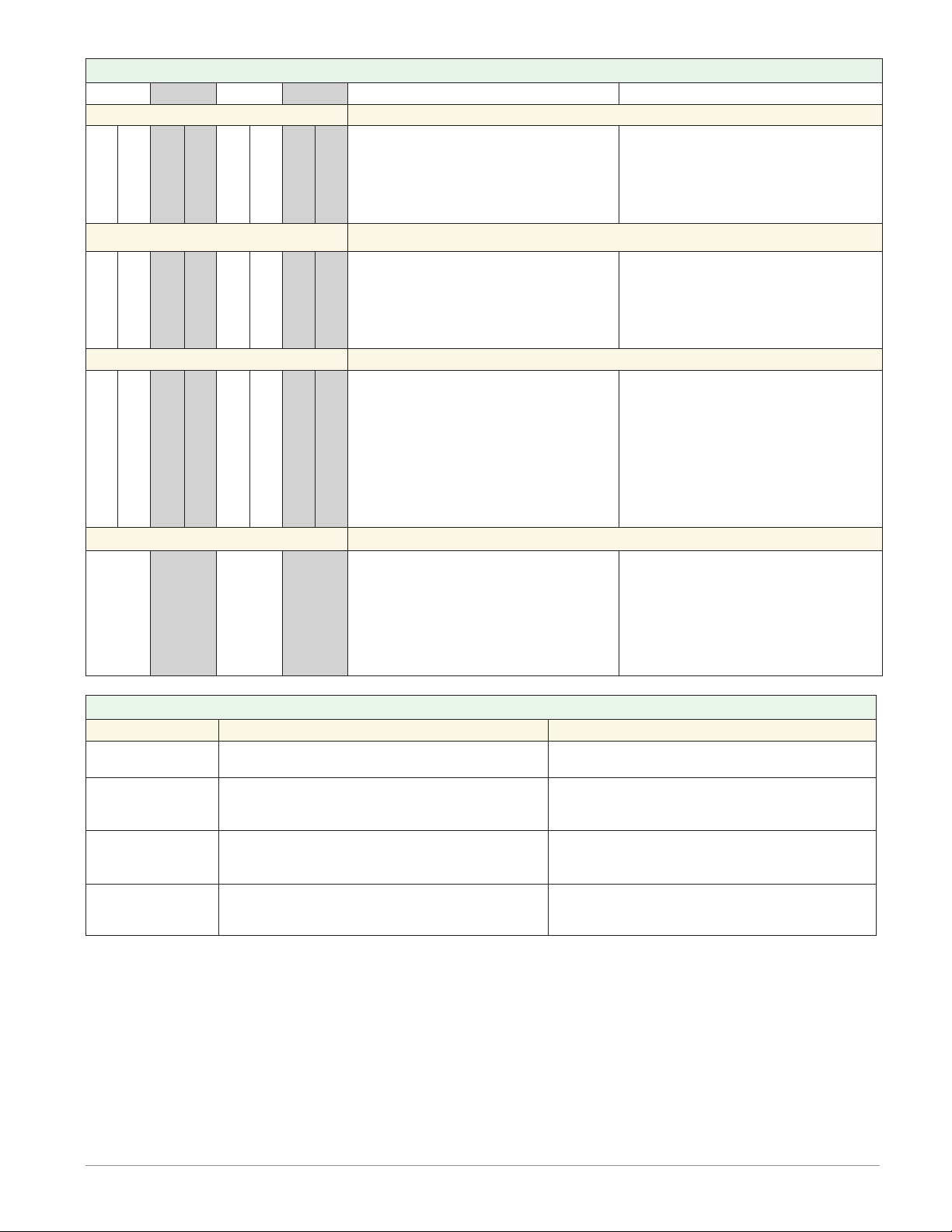
Module Status (Slot A,
B, D, or E)
Protocol (Standard
Bus - red or Modbus -
E
D
green)
Module outputs 1
through 16, all may
or may not be used
B
A
depending on module
type
RM
Control
Slot C
RM
Control
Slot C
Power
Supply
OIT
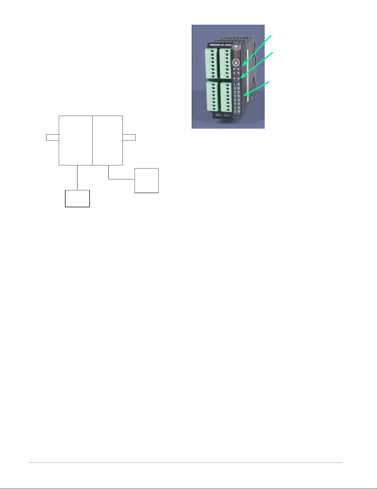
Module Orientation
The picture below represents one of six possible RM
modules. All six will have four slots on the face (slot
A, B, D, and E) and one on the bottom (slot C) not
shown. All of these slots are not always used on all
modules. On the face of the module there is a button
(white circle) under the Zone address (5) that when
pushed and held has the following functions:
1.For any module, push and hold for ~ 2 seconds. The
address will intensify indicating that it can now be
changed. Release and repeatedly press to change
to the desired unique address
2.For the control module, if equipped with the Mod-
bus protocol (RMCxxxxxxxxx1xx) pushing and
holding this button for ~ 6 seconds will cause the
display to reflect P for protocol. Releasing the button and then pushing it again (within 6 seconds)
the display will toggle between N (Modbus) and S
(Standard Bus). Valid addresses for Modbus and
Standard bus range from 1 -16 (1 - 9, A is 10, B is
11, C is 12, D is 13, E is 14, F is 15, and h is 16).
The Access module is shipped at address J or 17
Watlow EZ-ZONE® RMC Module • 10 • Chapter 1 Overview
Page 14
Input
Some input/output combinations not possible, see ordering matrix
Zone and Status
LED
Zone Selection
Output Status
LEDs
2
3
456
1
10
11
12
13
14
9
7
81516
Button
D
E
B
A
S
M
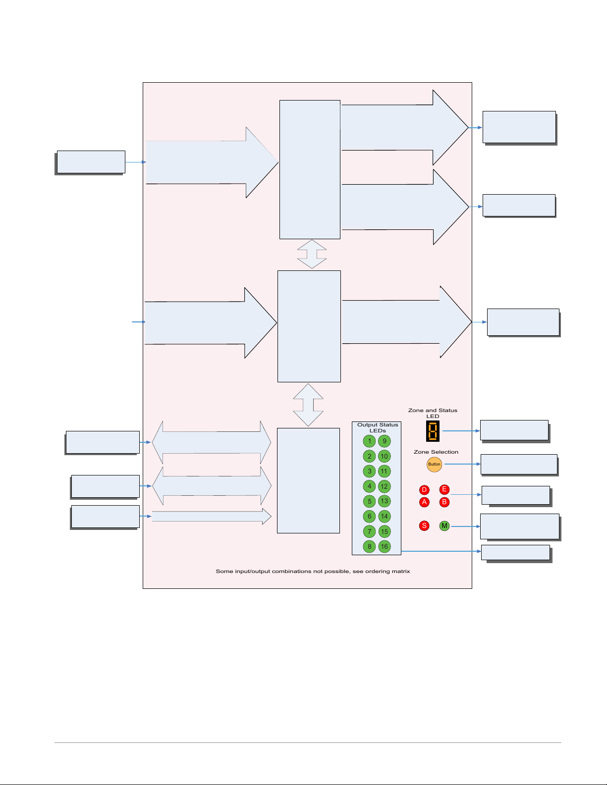
Function
EZ-ZONE RM-Control Module - System Diagram
with 6-Digital Input/Output card in slot E
Output
Function
Input Sensor
Analog Input 1, 2, 3, 4
None, CT, Thermocouple, RTD (100, 1k),
Thermistor (5k, 10K, 20k, 40k), Process
(mV, V, mA) or 1k Potentionmeter
Digital Input (or output) 7 - 12
Switch contact or volts dc
Current
Transformer
Sense (CT),
Limit or
PID Controller
(When ordered, all
loops have Ramp/
Soak, max 25 files
& 400 steps.)
Slot A, B, or D
(optional)
6 - Digital
Inputs or Outputs
Slot E
Output 1, 3, 5
None, Switched dc/Open Collector,
5A Mechanical Relay Form C, Process,
or 0.5A Solid-State Relay Form A
Class 1 Div II not available
with mechanical relay
outputs.
Output 2, 4, 6
None, 15A NO-ARC Form A,
Switched dc, 5A Mechanical Relay
Form A, or 0.5A Solid-State Relay
Form A
Digital Output (or input) 7 - 12
Switch contact or volts dc
Off, Heat, Cool,
Alarm, Retransmit,
Duplex, Event or Limit
Off, Heat, Cool,
Alarm, Event or Limit
If Limit, this output
must be Limit.
Off, Heat, Cool,
Alarm, Event
or Control
RUI,
PC, PLC or HMI
Other RM Modules
Power Supply
EIA - 485 Communications
Standard Bus
(optional Modbus RTU)
Inter-module Bus
20.4 to 30.8 Vac or Vdc
Indicates Zone
Address
Modbus RTU
Address 1 - 16
Standard Bus
Zone 1 - 16
Supervisory &
Power Board
Push to select Zone
Address and Protocol
Card Status
Slots A, B, D, E
Indicates communi-
Slot C
cations activity (Modbus
or Standard Bus)
Indicates I/O
Status
Watlow EZ-ZONE® RMC Module • 11 • Chapter 1 Overview
Page 15
Some input/output combinations not possible, see ordering matrix
Zone and Status
LED
Zone Selection
Output Status
LEDs
2
3
4
5
6
1
10
11
12
13
14
9
7
81516
Button
D
E
B
A
S
M
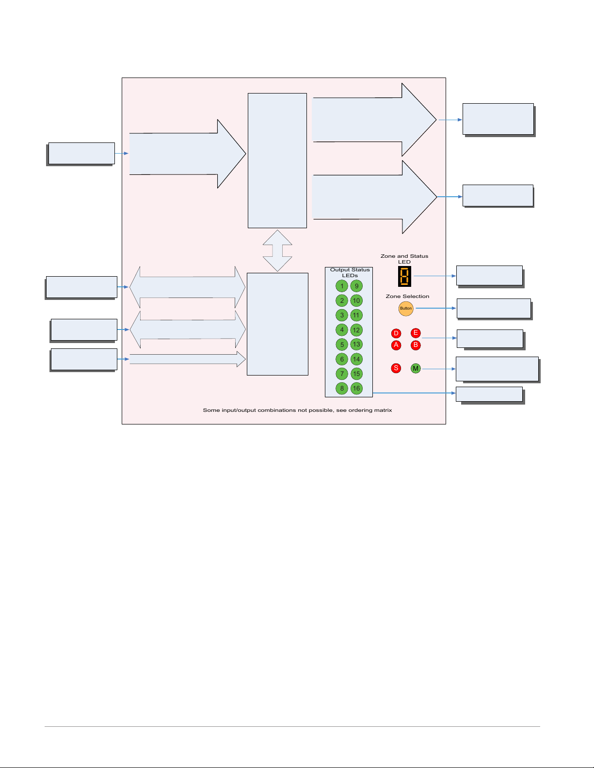
Input
Function
EZ-ZONE RM-Control Module - System Diagram
without 6-Digital Input/Output card in slot E
Output
Function
Input Sensor
RUI,
PC, PLC or HMI
Other RM Modules
Power Supply
Analog Input 1, 2, 3, 4
None, CT, Thermocouple, RTD (100, 1k),
Thermistor (5k, 10K, 20k, 40k), Process
(mV, V, mA) or 1k Potentionmeter
EIA - 485 Communications
Standard Bus
(optional Modbus RTU)
Inter-module Bus
20.4 to 30.8 Vac or Vdc
Current
Transformer
Sense (CT),
Limit or
PID Controller
(When ordered, all
loops have Ramp/
Soak, max 25 files
& 400 steps.)
Slot A, B, D or E
(optional)
Modbus RTU
Address 1 - 16
Standard Bus
Zone 1 - 16
Supervisory &
Power Board
Slot C
Output 1, 3, 5, 7
None, Switched dc/Open Collector,
5A Mechanical Relay Form C, Process,
or 0.5A Solid-State Relay Form A
Class 1 Div II not available
with mechanical relay
outputs.
Output 2, 4, 6, 8
None, 15A NO-ARC Form A,
Switched dc, 5A Mechanical Relay
Form A, or 0.5A Solid-State Relay
Form A
Off, Heat, Cool,
Alarm, Retransmit,
Duplex, Event or Limit
Off, Heat, Cool,
Alarm, Event or Limit
If Limit, this output
must be Limit.
Indicates Zone
Address
Push to select Zone
Address and Protocol
Card Status
Slots A, B, D, E
Indicates communications
activity (Modbus or Standard Bus)
Indicates I/O
Status
Watlow EZ-ZONE® RMC Module • 12 • Chapter 1 Overview
Page 16
2
Chapter 2: Install and Wire
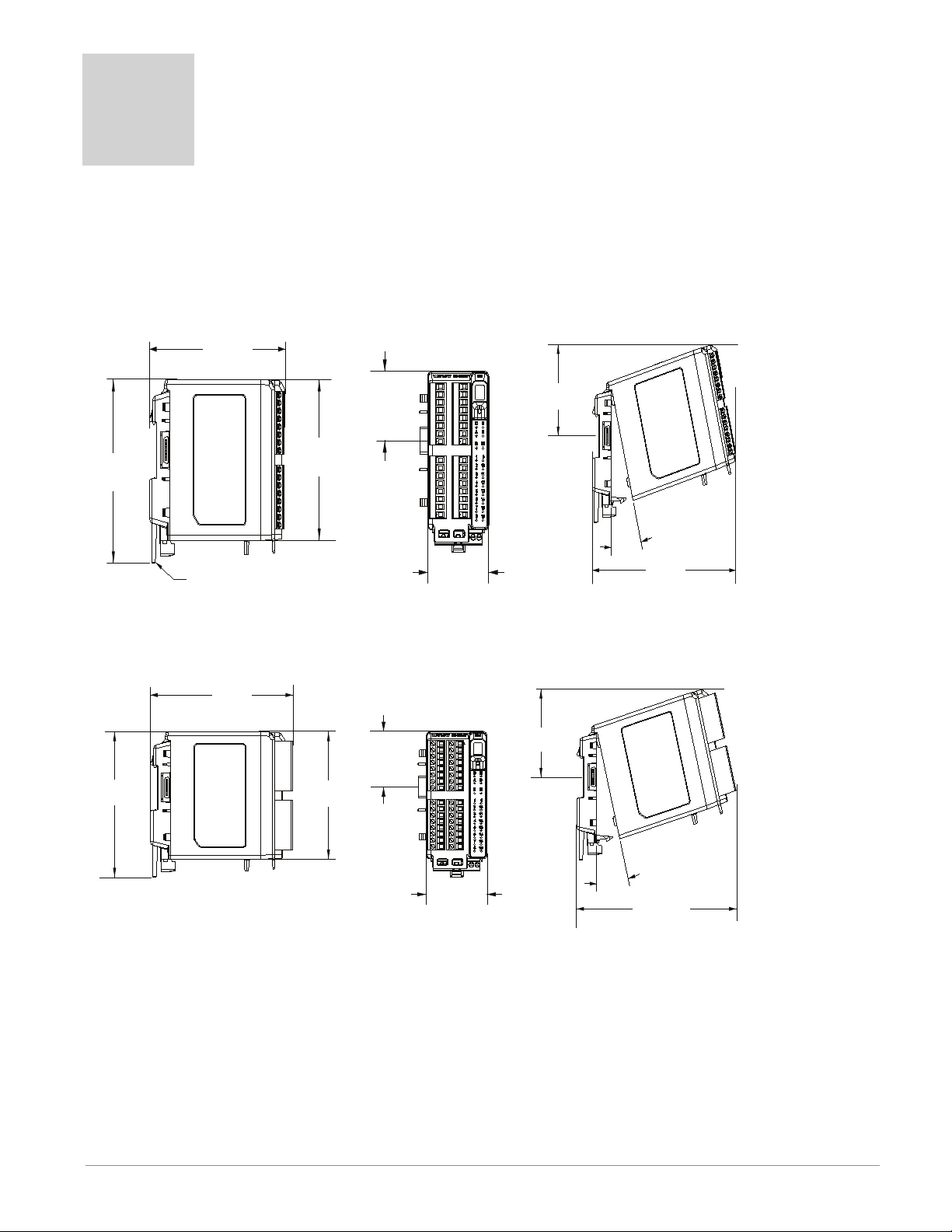
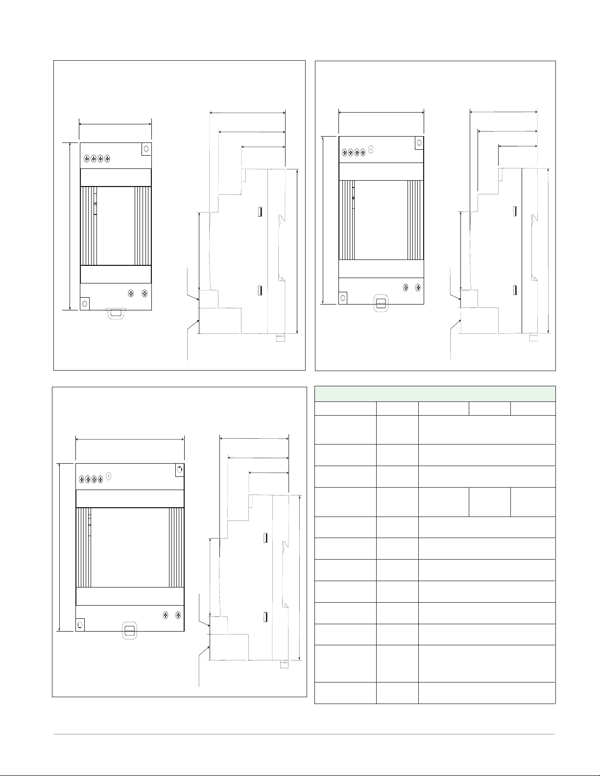
Dimensions
As can be seen below the dimensions of the RMC module will change slightly based on the type of connector
used.
Module Removal Clearance Standard Connectors
147.07 mm
( 5.8 in )
75.08 mm
( 3.0 in )
116.08 mm
( 4.57 in )
Latch in open position
44.45 mm
( 1.75 in )
101.60 mm
( 4.00 in )
51.56 mm
( 2.03 in )
Module Removal Clearance Straight Connectors
155 mm
( 6.10 )
75.08 mm
( 3.0 in )
116.08 mm
( 4.57 in )
44.45 mm
( 1.75 in )
101.60 mm
( 4.00 in )
0
15
165 mm
( 6.50 in )
Module Removal Displacement
15
51.56 mm
( 2.03 in )
°
173.90 mm
( 6.85 in )
Module Removal Displacement
Watlow EZ-ZONE® RMC Module • 13 • Chapter 2 Install and Wire
Page 17

Dimensions
Chassis Mount Front View (Module Removed) - Screw Connection Pattern
58.67 mm
( 2.31 in )
32.77 mm
17.53 mm
( 0.69 in )
60.45 mm
( 2.38 in )
35.81 mm
( 1.41 in )
( 1.29 in )
35.05 mm
( 1.38 in )
The view above is representative of the modular backplane without the module.
Recommended chassis mount hardware:
1. #8 screw, 3/4" long
2. Torque to 10 -15 in-lb
3. No washers of any kind
51.56 mm
( 2.03 in )
16.76 mm
( 0.67 in )
Watlow EZ-ZONE® RMC Module • 14 • Chapter 2 Install and Wire
Page 18
DSP30
+ +
-
-
L N
DC LO
DC OK
123 4
5 6
53.00 mm
DSP30
2.087 in
91.00 mm
3.583 in
14.20 mm
9.75 mm
43.1 mm
91.00 mm
55.6 mm
49.00 mm
32.10 mm
0.559 in
1.697 in
0.384 in
3.583 in
2.189 in
1.929 in
1.264 in
DSP60
vout ADJ.
+ +
-
-
L N
DC LO
DC OK
123 4
5 6
DSP60
71.00 mm
2.795 in
91.00 mm
3.583 in
14.20 mm
9.75 mm
43.1 mm
91.00 mm
55.6 mm
49.00 mm
32.10 mm
0.559 in
1.697 in
0.384 in
3.583 in
2.189 in
1.929 in
1.264 in
DSP100
DC LO
DC OK
vout ADJ.
+ +
-
-
L N
123 4
5 6
DSP100
89.9 mm
3.539 in
91.00 mm
3.583 in
5
14.20 mm
9.75 mm
43.1 mm
91.00 mm
56.8 mm
49.00 mm
32.10 mm
0.559 in
1.697 in
0.384 in
3.583 in
2.236 in
1.929 in
1.264 in
Power Supplies
Power Supply Specifications
DSP 30 DSP60 DSP100
AC Input Volt-
age Range
Input Fre-
quency
DC Input Volt-
age range
VAC
Hz 47 - 63Hz
VDC 120 - 370VDC
Inrush Cur-
rent (115 /
A 25 / 50A 30 / 60A 30 / 60A
230VAC)
Output Volt-
age Accuracy
Over voltage
Protection
LED Indica-
tors
Operating
Temperature
Storage Tem-
perature
Operating Hu-
midity
Vibration (Op-
erating)
% ±1% of Nominal
V 120 - 145%
- - - -
- - - -
- - - - -25 to +85°C
- - - - 20 - 95% RH (non condensing)
- - - -
Safety Agency
Approvals
For a comprehensive listing of these specifications point your
browser to : http://us.tdk-lambda.com/lp/products/dsp-series.htm
90 - 264VAC, Class II double in-
sulated (No ground connection
required)
Green LED = On, Red LED = DC
Output Low
-25 to +71°C (Derate linearly
2.5%/°C from 55 to 71°C)
IEC 60068-2-6 (Mounting by rail:
Random wave, 10-500 Hz, 2G, ea.
along X, Y, Z axes 10 min/cycle,
60 min)
UL1310 Class 2(1), UL508 Listed,
UL60950-1, EN60950-1, CE
Watlow EZ-ZONE® RMC Module • 15 • Chapter 2 Install and Wire
Page 19
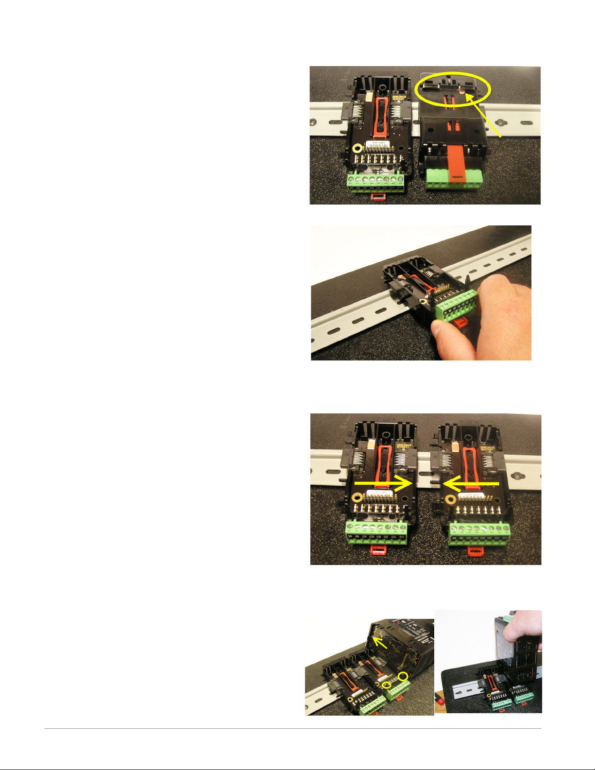
RMC Installation and Removal on a DIN Rail
Modular Backplane Connector
The picture on the right shows the Modular Backplane
Connector, both front and rear view. The rear view
is bringing in to focus a metal clip. If the DIN rail is
grounded the Modular Backplane Connector and the
module connected to it will be also (recommended).
Installing the Modular Backplane Connector
Step 1
Hook backplane assembly to upper edge of DIN rail,
(see rear view above, backplane hook detail that
mates with upper rail edge is circled)
Step 2
Next, rotate back plane assembly downward to en
gage the lower edge of the rail. (Note: Din Rail clip ping distance ranges from 1.366 -1.389 inches. The
back plane assembly will not latch onto the rail suc cessfully if the rail is out of dimension).
Step 3
For final positioning and locking, the red tab is to
be pushed upward to further engage the bottom
edge of the rail with an over center snap action
latch. (The red locking tab protrudes from the bot tom side of the back plane assembly).
Installing Multiple Modular Backplane Connectors
Multiple modules are easily aligned and latched together. Each module includes matched mating geometry that facilitates accurate and consistent interconnections. The recommended method of multi-module
attachment is to first attach individual modules to
the rail separately and second to laterally slide the
modules together until they touch. (Refer to steps 1&2
above). When the multi-module system is attached and
laterally positioned to the desired placement the locking tab should be engaged to secure the control system
to the rail, (Refer to step 3 above).
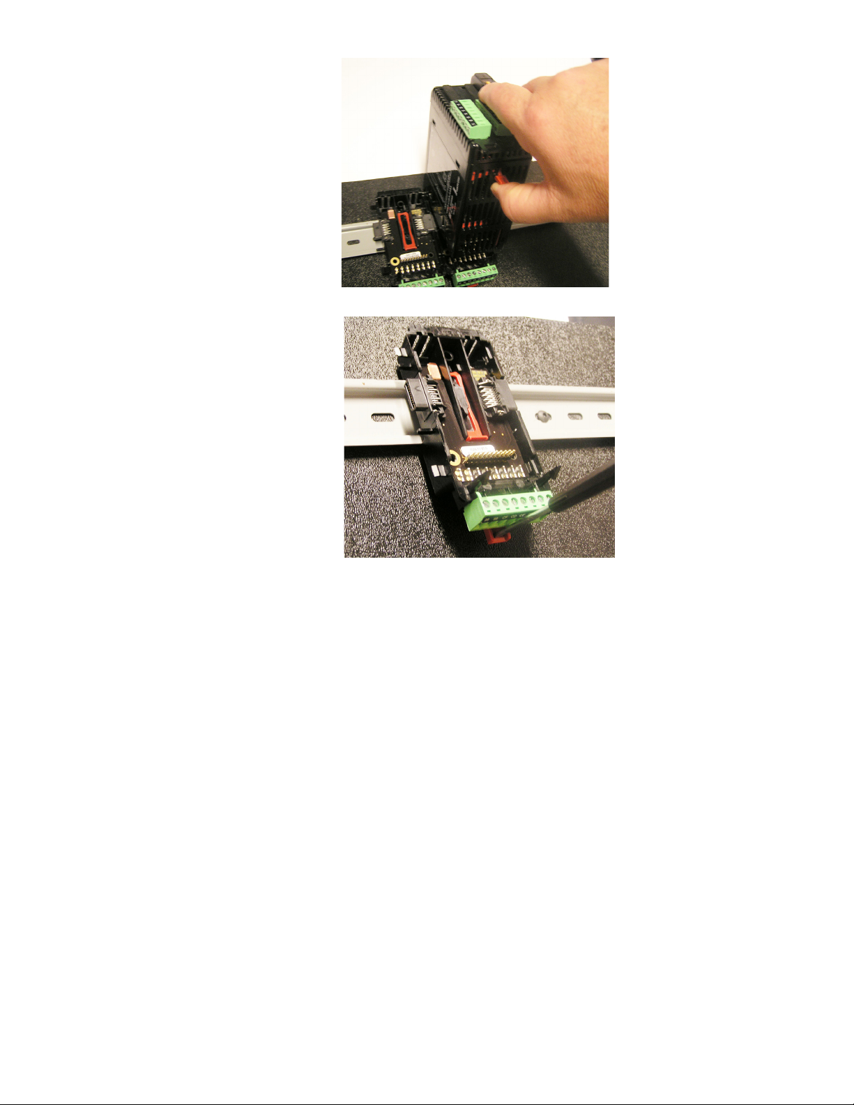
Module Installation
In the picture to the right notice that the arrow is
pointing at the top lip of the module (on side). When installing the module simply slide this lip over the top of
the Modular Backplane Connector and then push down
on the rear of the module where it will seat on the two
posts just above the green connector.
Watlow EZ-ZONE® RMC Module • 16 • Chapter 2 Install and Wire
Page 20
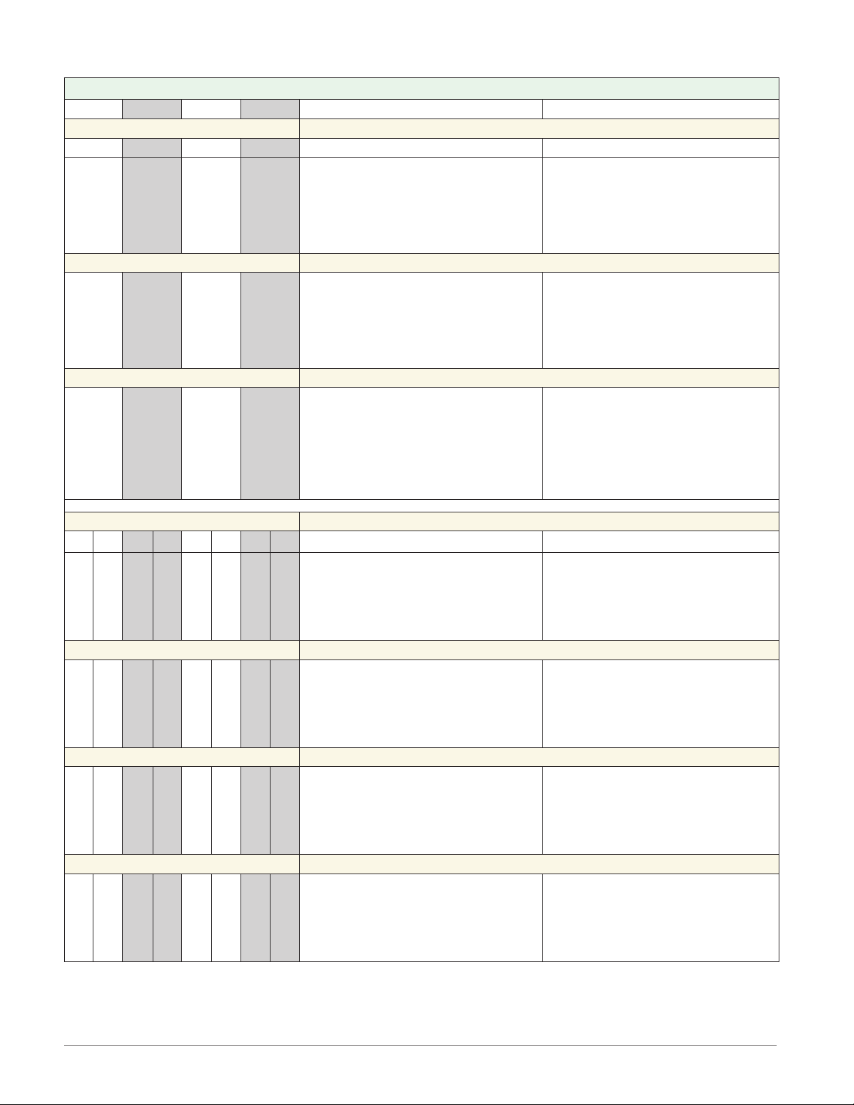
Module Removal
To remove a module from the
Modular Backplane Connector
find the red tab protruding from
the bottom of the module and
pull back on it as shown to the
right. While pulling back on the
red tab the two mounting posts
will release the module where the
module can then be lifted up and
out of the Modular Backplane
Connector.
Removal of the Modular Backplane Connector
A module can be removed from
the Modular Backplane Connector
by inserting a screw driver into
the red locking tab just behind
the green connector and applying
downward pressure on the tab by
lifting the screwdriver upwards.
When released, the tab will move
downward and the connector can
then be lifted up off of the DIN
rail.
Page 21
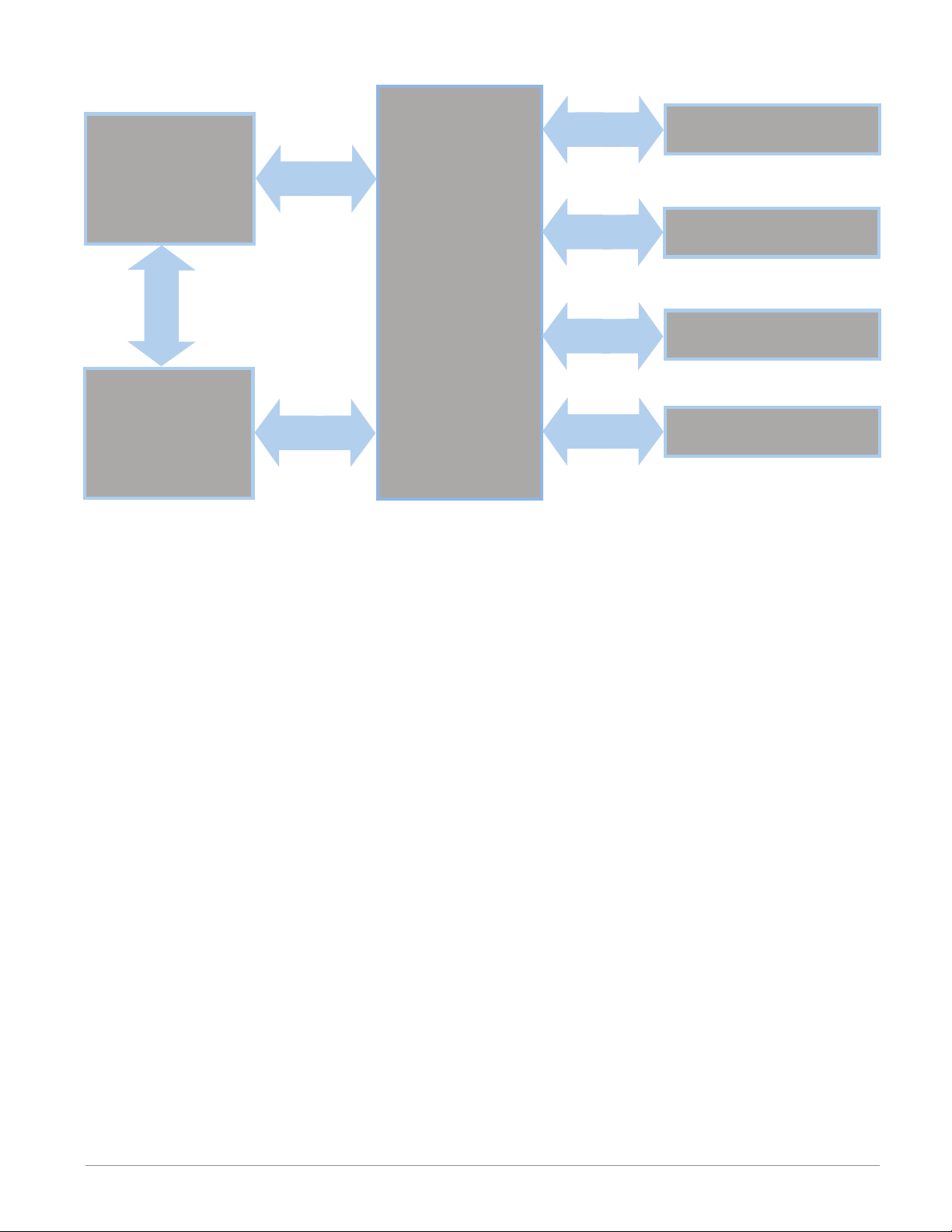
Wiring
Controller Module (RMCxxxxxxxxxxxx)
Slot A Slot B Slot D Slot E Terminal Function Configuration
Inputs Universal, RTD, Potentiometer and Thermistor Inputs 1 - 4
1 2 3 4
Universal/Thermistor Input
T1
S1
R1
T1
S1
T2
S2
R2
T2
S2
T3
S3
R3
T3
S3
T4
S4
R4
T4
S4
B7
D7
D8
D9
D10
D11
D12
Z7
T_ (RTD) or current +S_ (RTD), thermocouple -, current -, potentiometer or volts R_ (RTD), thermocouple + or volts +, potentiometer wiper
Current Transformer Inputs 1 - 4
mA ac
mA ac
Digital Inputs 7 - 12
Common
dc +input
dc +input
dc +input
dc +input
dc +input
dc +input
Internal Supply
Part # Digits 4, 6, 8, 10
Input 1: RMC[1,2,3,4,5,6]xxxxxxxxxxx
Input 2: RMCxx[1,2,5,6]xxxxxxxxx
Input 3: RMCxxxx[1,2,5,6]xxxxxxx
Input 4: RMCxxxxxx[1,2,5,6]xxxxx
Current Transformer
Part # Digits 4, 6, 8, 10
Input 1: RMC[7]xxxxxxxxxxx
Input 2: RMCxx[7]xxxxxxxxx
Input 3: RMCxxxx[7]xxxxxxx
Input 4: RMCxxxxxx[7]xxxxx
Digital Inputs/Outputs
Part # Digit 11
Slot A: Option not valid
Slot B: Option not valid
Slot D: Option not valid
Slot E: RMCxxxxxxx[C]xxxx
Outputs Switched dc / Open Collector Outputs 1, 3, 5 and 7
1 2 3 4 5 6 7 8
X1
W1
Y1
F1
G1
H1
L1
K1
J1
W2
Y2
X3
W3
Y3
F3
G3
H3
L3
K3
J3
W4
Y4
X5
W5
Y5
F5
G5
H5
L5
K5
J5
X7
W7
Y7
W6
Y6
F7
G7
H7
L7
K7
J7
common
dc- (open collector)
dc+
W8Y8dc-
dc+
voltage or current voltage +
current +
normally open
common
normally closed
Switched DC/Open Collector
Part # Digits 5, 7, 9, 11
Output 1: RMCx[U,D,E,F,G]xxxxxxxxxx
Output 3: RMCxxx[U,D,E,F,G]xxxxxxxx
Output 5: RMCxxxxx[U,D,E,F,G]xxxxxx
Output 7: RMCxxxxxxx[U,D,E,F,G]xxxx
Switched dc Outputs 2, 4, 6 and 8
Switched DC
Part # Digits 5, 7, 9, 11
Output 2: RMCx[E,K,P]xxxxxxxxxx
Output 4: RMCxxx[E,K,P]xxxxxxxx
Output 6: RMCxxxxx[E,K,P]xxxxxx
Output 8: RMCxxxxxxx(E,K,P]xxxx
Universal Process Outputs 1, 3, 5 and 7
Universal Process
Part # Digits 5, 7, 9, 11
Output 1: RMCx[N,P,R,S]xxxxxxxxxx
Output 3: RMCxxx[N,P,R,S]xxxxxxxx
Output 5: RMCxxxxx[N,P,R,S]xxxxxx
Output 7: RMCxxxxxxx[N,P,R,S]xxxx
Form C - Mechanical Relay Outputs 1, 3, 5 and 7
Mechanical Relay 5 A, Form C
Part # Digits 5, 7, 9, 11
Output 1: RMCx[H,J,K,L,M]xxxxxxxxxx
Output 3: RMCxxx[H,J,K,L,M]xxxxxxxx
Output 5: RMCxxxxx[H,J,K,L,M]xxxxxx
Output 7: RMCxxxxxxx[H,J,K,L,M]xxxx
Watlow EZ-ZONE® RMC Module • 18 • Chapter 2 Install and Wire
Page 22
Controller Module (RMCxxxxxxxxxxxx)
Slot A Slot B Slot D Slot E Terminal Function Configuration
Outputs (cont.) NO-ARC Form A - Mechanical Relay Outputs 2, 4, 6 and 8
NO-ARC 15 A, Form A
L2
K2
L2
K2
L1K1L2K2L3K3L4K4L5K5L6K6L7K7L8K8normally open
L4
K4
L4
K4
L6
K6
L6
K6
L8K8normally open
common
L8K8normally open
common
common
B7
Common
D7
open collector/ switched dc
D8
open collector/ switched dc
D9
D10
D11
D12
open collector/ switched dc
open collector/ switched dc
open collector/ switched dc
open collector/ switched dc
Z7
Internal Supply
Form A - Mechanical Relay Outputs 2, 4, 6 and 8
Solid State Relay Outputs 1 - 8
Digital Outputs 7 - 12
Part # Digits 5, 7, 9, 11
Output 2: RMCx[D,J,Y]xxxxxxxxxx
Output 4: RMCxxx[D,J,Y]xxxxxxxx
Output 6: RMCxxxxx[D,J,Y]xxxxxx
Output 8: RMCxxxxxxx[D,J,Y]xxxx
Mechanical Relay 5 A, Form A
Part # Digits 5, 7, 9, 11
Output 2: RMCx[B,F]xxxxxxxxxx
Output 4: RMCxxx[B,F]xxxxxxxx
Output 6: RMCxxxxx[B,F]xxxxxx
Output 8: RMCxxxxxxx[B,F]xxxx
Solid-State Relay 0.5 A, Form A
Part # Digits 5, 7, 9, 11
Output 1: RMCx[G,M,S,T,Y,Z]xxxxxxxxxx
Output 2: RMCx[G,M,S,T,Y,Z]xxxxxxxxxx
Output 3: RMCxxx[G,M,S,T,Y,Z]xxxxxxxx
Output 4: RMCxxx[G,M,S,T,Y,Z]xxxxxxxx
Output 5: RMCxxxxx[G,M,S,T,Y,Z]xxxxxx
Output 6: RMCxxxxx[G,M,S,T,Y,Z]xxxxxx
Output 7: RMCxxxxxxx[G,M,S,T,Y,Z]xxxx
Output 8: RMCxxxxxxx[G,M,S,T,Y,Z]xxxx
Digital Inputs/Outputs
Part # Digit 11
Slot A: Option not valid
Slot B: Option not valid
Slot D: Option not valid
Slot E: RMCxxxxxxx[C]xxxx
Power and Communications
Slot C Terminal Function Configuration
98
99
CF
CD
CE
CC
CA
CB
CZ
CX
CY
Power input: ac or dc+
Power input: ac or dc-
Standard Bus EIA-485 common
Standard Bus EIA-485 T-/RStandard Bus EIA-485 T+/R+
Standard Bus or Modbus RTU EIA-485 common
Standard Bus or Modbus RTU EIA-485 T-/RStandard Bus or Modbus RTU EIA-485 T+/R+
Inter-module Bus
Inter-module Bus
Inter-module Bus
All
Standard Bus
Part # Digit 13
RMCxxxxxxxxxAxx
Standard Bus or Modbus
Part # Digit 13
RMCxxxxxxxxx1xx
Inter-module Bus
Watlow EZ-ZONE® RMC Module • 19 • Chapter 2 Install and Wire
Page 23
Slot D
Slot A
RMC Front View
Standard Connector
Slot E
Slot B
98
99
power
Watlow EZ-ZONE® RMC Module • 20 • Chapter 2 Install and Wire
Page 24
RMC Module Isolation Diagram
Controller Power Supply
20.4 to 30.8VÎ (dc)
20.4 to 30.8VÅ (ac)
Safety Isolation
Mechanical Relay,
Solid-State Relay,
NO-ARC Relay
Outputs
Safety Isolation
Safety Isolation
Controller
Low Voltage Power Bus
Low-voltage Isolation: 42V peak
Safety Isolation: 1,528VÅ (ac)
No Isolation
No Isolation
Low-voltage
Isolation
Low-voltage
Isolation
Digital Inputs & Outputs
Switched DC, Open Collector,
Process outputs
Analog Input 1 - 4
Communications Ports
Watlow EZ-ZONE® RMC Module • 21 • Chapter 2 Install and Wire
Page 25
Warning: ç
Slot A, B, D, E
Use National Electric (NEC) or other
country-specific standard wiring and
safety practices when wiring and
connecting this controller to a power
source and to electrical sensors or peripheral devices. Failure to do so may
result in damage to equipment and
property, and/or injury or loss of life.
Note:
Maximum wire size termination and
torque rating:
• 0.0507 to 3.30 mm2 (30 to 12 AWG)
single-wire termination or two 1.31
mm2 (16 AWG)
• 0.8 Nm (7.0 in-lb.) torque
Note:
Adjacent terminals may be labeled
differently, depending on the model
number.
Note:
To prevent damage to the controller,
do not connect wires to unused terminals.
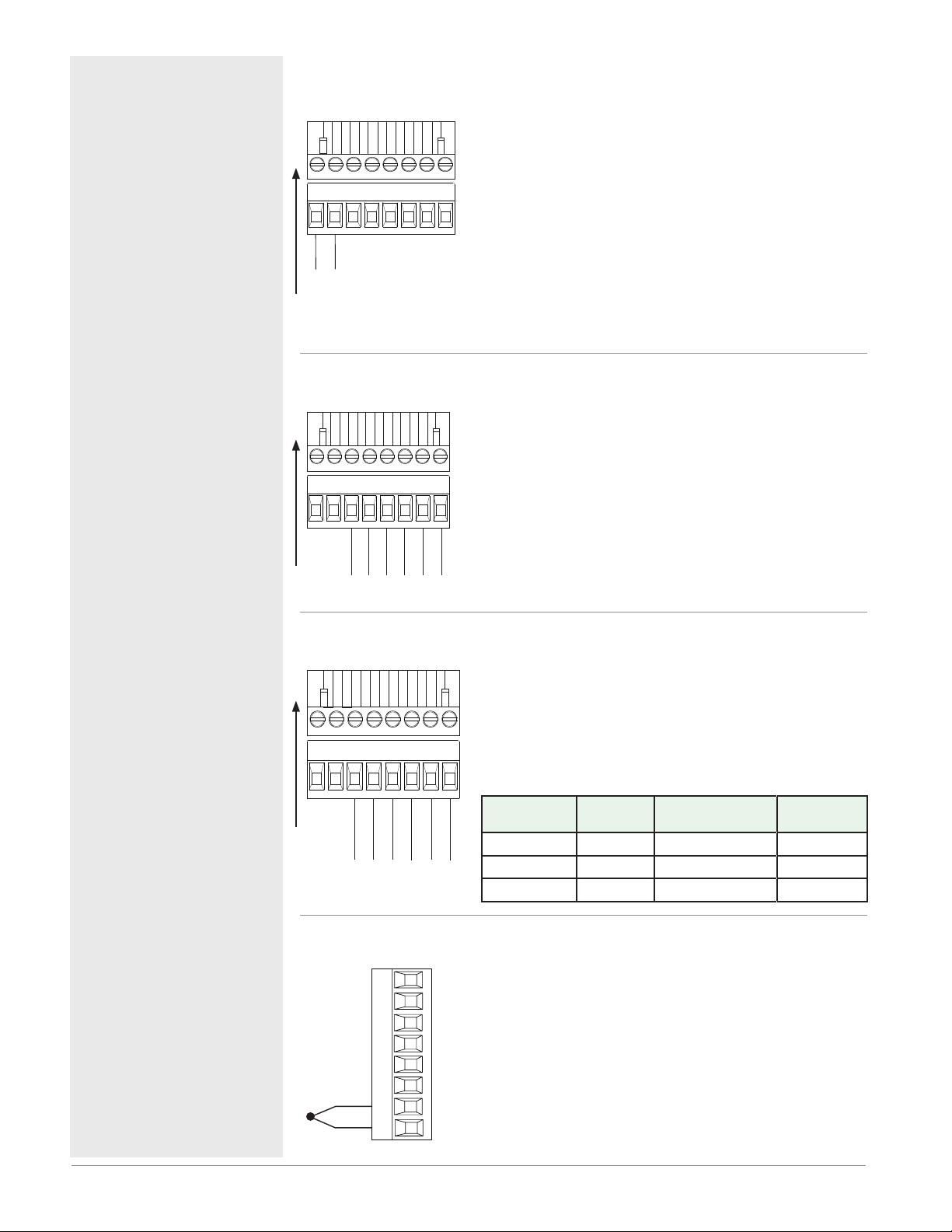
Controller Module Wiring (RMCxxxxxxxxxxxx)
Low Power RMC - All Model Numbers
• 20.4 to 30.8 V Å (ac) / Î (dc) 14VA
• 47 to 63 Hz
• Controller module power consumption, 7 Watts maxi-
98
99
mum
• 31 Watts maximum power available for P/S part
#:0847-0299-0000
power
• 60 Watts maximum power available for P/S part
#:0847-0300-0000
• 91 Watts maximum power available for P/S part
#:0847-0301-0000
• Class 2 or Safety Extra Low Voltage (SELV) power
source required to meet UL compliance standards
Communications RMC Part # Digit 13 is A
• CF, CD, CE - Standard Bus EIA485 Communications
• CZ, CX, CY - Inter-module Bus EIA485 Communications
• Do not route network wires with power wires. Connect
network wires in daisy-chain fashion when connecting
multiple devices in a network
CF CD
Slot C
CE
CZ
CX
CY
Note:
Maintain electrical isolation between
digital input-outputs, switched dc/open
collector outputs and process outputs
to prevent ground loops.
Note:
If the last two digits of the part number
are "12", this equipment is suitable for
use in CLASS I, DIVISION 2, Groups A,
B, C and D or Non-Hazardous locations
only. Temperature Code T4
Warning: ç
Explosion Hazard – Substitution of
component may impair suitability for
CLASS I, DIVISION 2.
Warning: ç
Explosion Hazard - Do not disconnect
while the circuit is live or unless the
area is known to be free of ignitable
concentrations of flammable substances.
Standard Bus
Common
T- / R-
Common
T+ / R+
Inter-module Bus
-
+
Communications RMC Part # Digit 13 is 1
Slot C
CC CA
CB
Modbus
T- / R-
CZ CX
Common
T+ / R+
Inter-module Bus
Common
• CC, CA, CB - Modbus and Standard Bus EIA485 Communications (selectable via push button under zone address)
• CZ, CX, CY - Inter-module Bus EIA485 Communications
• Do not route network wires with power wires. Connect
CY
network wires in daisy-chain fashion when connecting
multiple devices in a network
-
+
Modbus-IDA
Terminal
EIA/TIA-
485 Name
Watlow Terminal
DO A CA or CD T-/R-
D1 B CB or CE T+/R+
common common CC or CF common
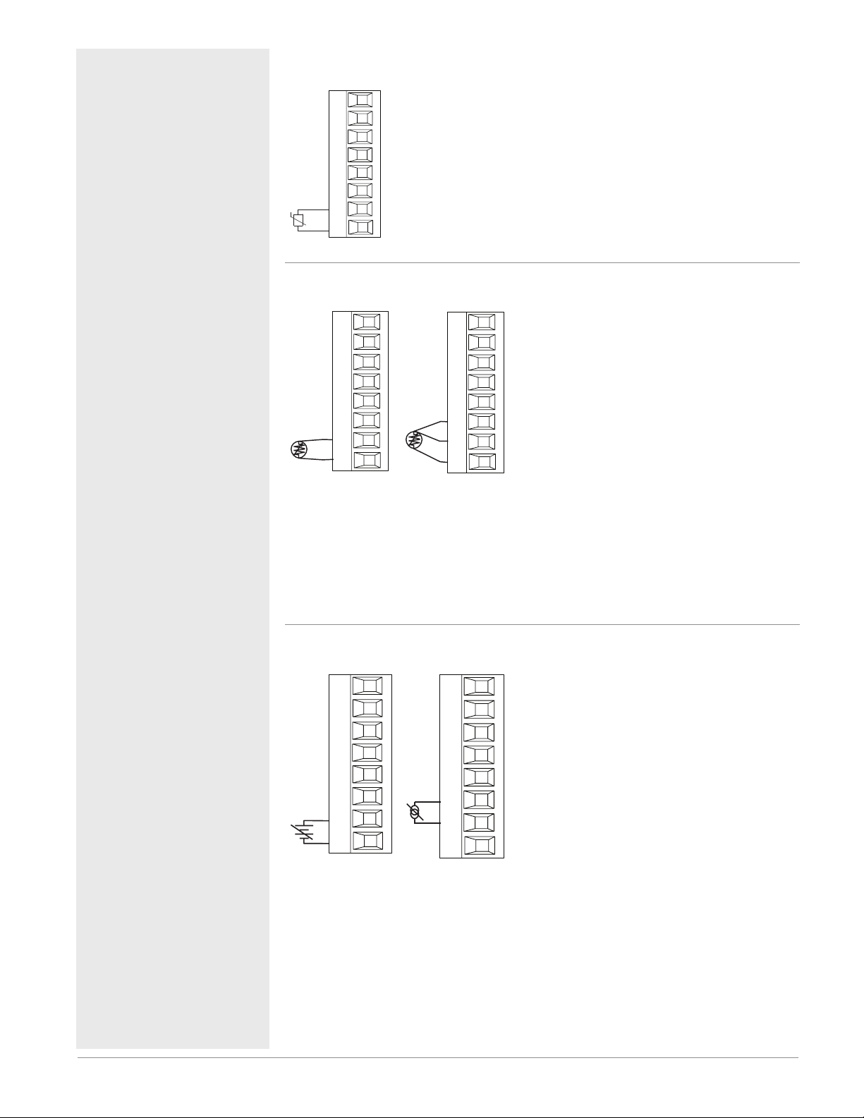
Input 1, 2, 3, 4 Thermocouple RMC Part # Digits 4, 6, 8, 10
• >20 MΩ input impedance
• 3 microampere open-sensor detection
• Thermocouples are polarity sensitive. The negative lead
(usually red) must be connected to S terminal
• To reduce errors, the extension wire for thermocouples
must be of the same alloy as the thermocouple.
Input 1: RMC(1,3,5)xxxxxxxxxxx
-
S_
+
R_
Input 2: RMCxx(1,5)xxxxxxxxx
Input 3: RMCxxxx(1,5)xxxxxxx
Input 4: RMCxxxxxx(1,5)xxxxx
Label
Function
Watlow EZ-ZONE® RMC Module • 22 • Chapter 2 Install and Wire
Page 26
Warning: ç
Slot A, B, D, E
RTD
Slot A, B, D, E
RTD
Slot A, B, D, E
Slot A, B, D, E
Slot A, B, D, E
Use National Electric (NEC) or other
country-specific standard wiring and
safety practices when wiring and
connecting this controller to a power
source and to electrical sensors or peripheral devices. Failure to do so may
result in damage to equipment and
property, and/or injury or loss of life.
Note:
Maximum wire size termination and
torque rating:
• 0.0507 to 3.30 mm2 (30 to 12 AWG)
single-wire termination or two 1.31
mm2 (16 AWG)
• 0.8 Nm (7.0 in-lb.) torque
Note:
Adjacent terminals may be labeled
differently, depending on the model
number.
Note:
To prevent damage to the controller,
do not connect wires to unused terminals.
Note:
Maintain electrical isolation between
digital input-outputs, switched dc/open
collector outputs and process outputs
to prevent ground loops.
Note:
If the last two digits of the part number
are "12", this equipment is suitable for
use in CLASS I, DIVISION 2, Groups A,
B, C and D or Non-Hazardous locations
only. Temperature Code T4
Warning: ç
Explosion Hazard – Substitution of
component may impair suitability for
CLASS I, DIVISION 2.
Warning: ç
Explosion Hazard - Do not disconnect
while the circuit is live or unless the
area is known to be free of ignitable
concentrations of flammable substances.
Input 1, 2, 3, 4 Thermistor RMC Part # Digits 4, 6, 8, 10
• >20 MΩ input impedance
Input 1: RMC(2,4,6)xxxxxxxxxxx
Input 2: RMCxx(2,6)xxxxxxxxx
Input 3: RMCxxxx(2,6)xxxxxxx
Input 4: RMCxxxxxx(2,6)xxxxx
S_
R_
Input 1, 2, 3, 4 RTD RMC Part # Digits 4, 6, 8, 10
• platinum, 100 and 1,000 Ω @ 0°C
• calibration to DIN curve (0.00385 Ω/Ω/°C)
• 20 Ω total lead resistance
• RTD excitation current of 0.09 mA typical.
Each ohm of lead resistance may affect the
reading by 0.03°C for 100 Ω.
S2
S3
S_
R_
S1
2-wire
T_
S3
S_
R_
S1
3-wire
• For 3-wire RTDs, the S1 lead (usually
white) must be connected to R terminal
• For best accuracy use a 3-wire RTD to compensate for lead-length resistance. All three
lead wires must have the same resistance.
Input 1: RMC(1,3,5)xxxxxxxxxxx
(S1,R1),(T1-S1-R1)
Input 2: RMCxx(1,5)xxxxxxxxx
(S2,R2),(T2-S2-R2)
Input 3: RMCxxxx(1,5)xxxxxxx
(S3,R3),(T3-S3-R3)
Input 4: RMCxxxxxx(1,5)xxxxx
(S4,R4),(T4-S4-R4)
Input 1, 2, 3, 4 Process RMC Part # Digits 4, 6, 8, 10
• 0 to 20 mA @ 100 Ω input impedance
+
-
S_
+
R_
volts
T_
-
S_
amperes
• 0 to 10VÎ (dc) @ 20 kΩ input impedance
• 0 to 50 mVÎ (dc) @ 20 MΩ input impedance
• scalable
Input 1: RMC(1,3,5)xxxxxxxxxxx
(S1-/R1+),(T1+/S1-)
Input 2: RMCxx(1,5)xxxxxxxxx
(S2-/R2+),(T2+/S2-)
Input 3: RMCxxxx(1,5)xxxxxxx
(S3-/R3+),(T3-S3-R3)
Input 4: RMCxxxxxx(1,5)xxxxx
(S4-/R4+),(T4+/S4-)
Watlow EZ-ZONE® RMC Module • 23 • Chapter 2 Install and Wire
Page 27
Warning: ç
Slot A, B, D, E
Slot A, B, D, E
12A
Is = IpT/R = 50mA
Use National Electric (NEC) or other
country-specific standard wiring and
safety practices when wiring and
connecting this controller to a power
source and to electrical sensors or peripheral devices. Failure to do so may
result in damage to equipment and
property, and/or injury or loss of life.
Note:
Maximum wire size termination and
torque rating:
• 0.0507 to 3.30 mm2 (30 to 12 AWG)
single-wire termination or two 1.31
mm2 (16 AWG)
• 0.8 Nm (7.0 in-lb.) torque
Note:
Adjacent terminals may be labeled
differently, depending on the model
number.
Note:
To prevent damage to the controller,
do not connect wires to unused terminals.
Note:
Maintain electrical isolation between
digital input-outputs, switched dc/open
collector outputs and process outputs
to prevent ground loops.
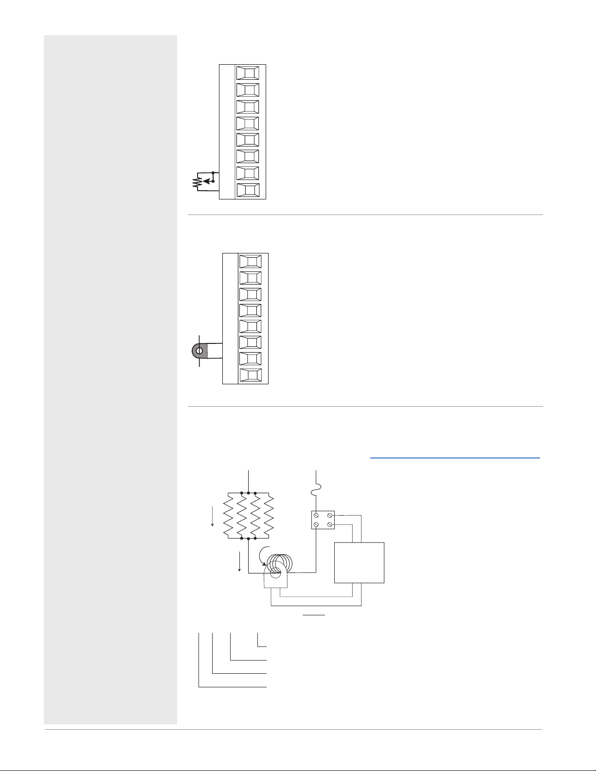
Input 1, 2, 3, 4 Potentiometer RMC Part # Digits 4, 6, 8, 10
• Use a 1 kΩ potentiometer.
Input 1: RMC(1,3,5)xxxxxxxxxxx (S1/R1)
Input 2: RMCxx(1,5)xxxxxxxxx (S2/R2)
Input 3: RMCxxxx(1,5)xxxxxxx (S3/R3)
Input 4: RMCxxxxxx(1,5)xxxxx (S4/R4)
CW
S_
R_
CCW
Input 1, 2, 3, 4 Current Transformer RMC Part # Digits 4, 6, 8, 10
• Input range is 0 to 50 mA (ac).
• Current transformer part number: 16-0246
• 100 Ω input impedance
• Response time: 1 second maximum
• Accuracy +/-1 mA typical
Input 1: RMC(7)xxxxxxxxxxx (T1/S1)
Input 2: RMCxx(7)xxxxxxxxx (T2/S2)
Input 3: RMCxxxx(7)xxxxxxx (T3/S3)
T_
S_
Input 4: RMCxxxxxx(7)xxxxx (T4/S4)
Note:
If the last two digits of the part number
are "12", this equipment is suitable for
use in CLASS I, DIVISION 2, Groups A,
B, C and D or Non-Hazardous locations
only. Temperature Code T4
Warning: ç
Explosion Hazard – Substitution of
component may impair suitability for
CLASS I, DIVISION 2.
Warning: ç
Explosion Hazard - Do not disconnect
while the circuit is live or unless the
area is known to be free of ignitable
concentrations of flammable substances.
Warning: ç
Explosion Hazard - Dry contact closure
Digital Inputs shall not be used in Class
I Division 2 Hazardous Locations unless
switch used is approved for this application.
Example: Using a Current Transformer
L2 L1
3A x 4
12A
x 4 = 48A
:
48mA
Fuse
Turns around CT
CT Ratio R = 1000:1
48mA
CT Secondary Current
CT Primary Current
Turns around CT
Total current
SSR
CSC = Ip(full scale) = 50mA(R)/T
CSI = Output N
s
I
= Current in secondary of current transformer
p = Current in primary of current transformer
I
T = Number of turns through the primary of the transformer
R = Number of turns in the secondary of the current
transformer (Turns ratio, assuming one primary turn)
CSC = Current Scaling (parameter found in Current Menu
of Setup Page)
CSI = Current Source Instance (parameter found in Current
Menu of Setup Page)
Output N
Controller
CT Input
Watlow EZ-ZONE® RMC Module • 24 • Chapter 2 Install and Wire
Page 28
Warning: ç
Common
Collector out
Collector out
B7
D7
D8
D9
D10
D11
D12
Z7
Slot E
Collector out
Collector out
Collector out
Collector out
Internal Supply
Common
Internal
Supply
D12
D11
D10
D9
D8
B7
D7
Z7
Use National Electric (NEC) or other
country-specific standard wiring and
safety practices when wiring and
connecting this controller to a power
source and to electrical sensors or peripheral devices. Failure to do so may
result in damage to equipment and
property, and/or injury or loss of life.
Note:
Maximum wire size termination and
torque rating:
• 0.0507 to 3.30 mm2 (30 to 12 AWG)
single-wire termination or two 1.31
mm2 (16 AWG)
• 0.8 Nm (7.0 in-lb.) torque
Note:
Adjacent terminals may be labeled
differently, depending on the model
number.
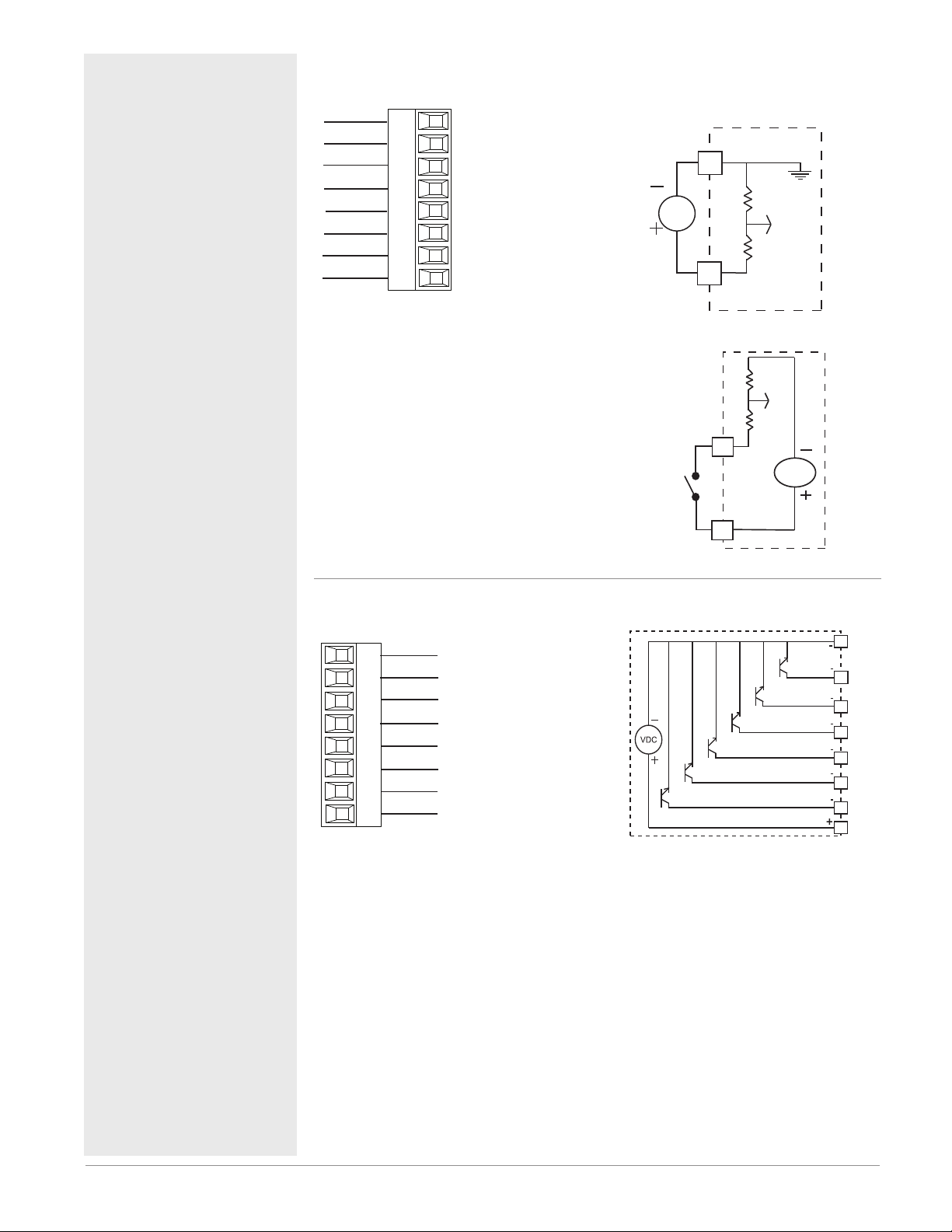
Digital Inputs 7 through 12 RMC Part # Digit 11 is C
Common
DC Input
DC Input
DC Input
DC Input
DC Input
DC Input
Internal Supply
Slot E
B7
D7
D8
D9
D10
D11
D12
Z7
Digital Input Event Con-
ditions
• Dry Contact
- Input inactive when >
100KΩ
- Input active when <
50Ω
• Voltage
- Input inactive when <
2V
- Input active when >
3V
• Six user configurable
Digital Inputs/outputs
per slot
- Slot E DIO 7-12
Voltage Input
_
B
Vdc
_
D
Dry Contact
common
Note:
To prevent damage to the controller,
do not connect wires to unused terminals.
Note:
Maintain electrical isolation between
digital input-outputs, switched dc/open
collector outputs and process outputs
to prevent ground loops.
Note:
If the last two digits of the part number
are "12", this equipment is suitable for
use in CLASS I, DIVISION 2, Groups A,
B, C and D or Non-Hazardous locations
only. Temperature Code T4
Warning: ç
Explosion Hazard – Substitution of
component may impair suitability for
CLASS I, DIVISION 2.
Warning: ç
Explosion Hazard - Do not disconnect
while the circuit is live or unless the
area is known to be free of ignitable
concentrations of flammable substances.
_
D
24 Vdc
_
Z
Digital Inputs/Outputs 7 through 12 RMC Part # Digit 11 is C
• Maximum switched
voltage is 32VÎ (dc)
• Internal supply pro-
vides a constant power output of 750mW
• Maximum output
sink current per output is 1.5A (external
class 2 or *SELV supply required)
• Total sink current for
all outputs not to exceed 8A
• Do not connect outputs in parallel
*Safety Extra Low Volt-
age
Suppressor Note:
Switching pilot duty inductive loads (relay coils, solenoids, etc.) with the mechanical relay, solid state relay or open
collector output options requires use of
an R.C. suppressor.
Watlow EZ-ZONE® RMC Module • 25 • Chapter 2 Install and Wire
Page 29

Warning: ç
Use National Electric (NEC) or other
country-specific standard wiring and
safety practices when wiring and
connecting this controller to a power
source and to electrical sensors or peripheral devices. Failure to do so may
result in damage to equipment and
property, and/or injury or loss of life.
Note:
Maximum wire size termination and
torque rating:
• 0.0507 to 3.30 mm2 (30 to 12 AWG)
single-wire termination or two 1.31
mm2 (16 AWG)
• 0.8 Nm (7.0 in-lb.) torque
Note:
Adjacent terminals may be labeled
differently, depending on the model
number.
Note:
To prevent damage to the controller,
do not connect wires to unused terminals.
Note:
Maintain electrical isolation between
digital input-outputs, switched dc/open
collector outputs and process outputs
to prevent ground loops.
Note:
If the last two digits of the part number
are "12", this equipment is suitable for
use in CLASS I, DIVISION 2, Groups A,
B, C and D or Non-Hazardous locations
only. Temperature Code T4
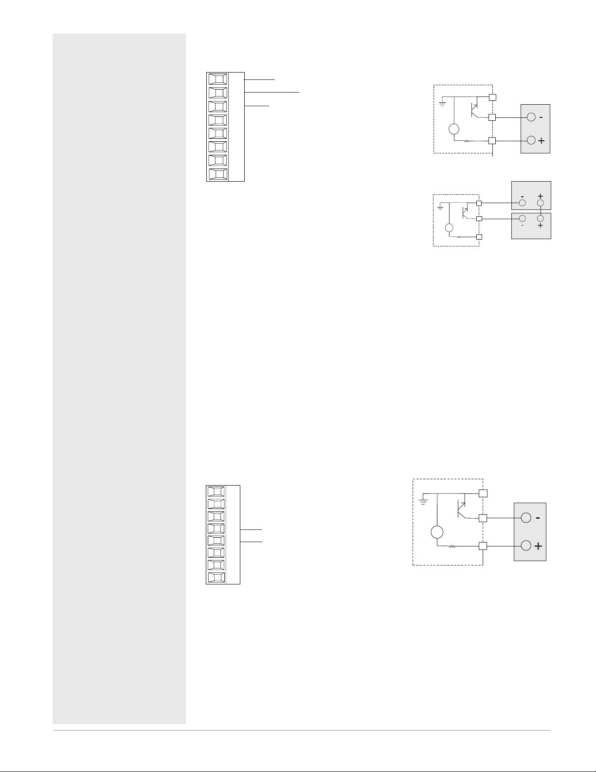
Switched DC Wiring Example Using DO 7-12
Collector Outputs
Vdc
Internal Circuitry
Note:
As a switched DC output; this output is a constant current output delivering
750 mW, current limited to 400 mA. The internal supply does have a maximum
open circuit voltage of 22 VDC and minimum open circuit voltage of 19 VDC.
Pin Z7 is shared to all digital outputs. This type of output is meant to drive solid
state relays, not mechanical relays.
As an open collector output, use an external power supply with the negative
wired to B7, the positive to the coil of a pilot mechanical relay and the other
side of the coil wired to D_. Each open collector output can sink 1.5 A with
the total for all open collector outputs not exceeding 8 amperes. Ensure that a
kickback diode is reversed wired across the relay coil to prevent damage to the
internal transistor.
Common
B_
D_
D_
D_
D_
D_
D_
Z_
Htr 2
Htr 3
Internal Supply
Htr 1
+
-
+
-
+
-
DC90-60C0-0000
Warning: ç
Explosion Hazard – Substitution of
component may impair suitability for
CLASS I, DIVISION 2.
Warning: ç
Explosion Hazard - Do not disconnect
while the circuit is live or unless the
area is known to be free of ignitable
concentrations of flammable substances.
Quencharc Note:
Switching pilot duty inductive loads
(relay coils, solenoids, etc.) with the
mechanical relay, solid state relay or
open collector output options requires
use of an R.C. suppressor.
Open Collector Wiring Example Using DO 7-12
Collector Outputs
Vdc
Internal Circuitry
Common
B_
D_
D_
D_
D_
D_
D_
Z_
Internal Supply
Diode
Power Supply
5 to 32 Vdc
-
Fuse
+
An example fuse is
Bussmann AGC-1 1/2
Relay
Watlow EZ-ZONE® RMC Module • 26 • Chapter 2 Install and Wire
Page 30
Warning: ç
or)
Slot A, B, D, E
Slot A, B, D, E
Use National Electric (NEC) or other
country-specific standard wiring and
safety practices when wiring and
connecting this controller to a power
source and to electrical sensors or peripheral devices. Failure to do so may
result in damage to equipment and
property, and/or injury or loss of life.
Note:
Maximum wire size termination and
torque rating:
• 0.0507 to 3.30 mm2 (30 to 12 AWG)
single-wire termination or two 1.31
mm2 (16 AWG)
• 0.8 Nm (7.0 in-lb.) torque
Note:
Adjacent terminals may be labeled
differently, depending on the model
number.
Note:
To prevent damage to the controller,
do not connect wires to unused terminals.
Note:
Maintain electrical isolation between
digital input-outputs, switched dc/open
collector outputs and process outputs
to prevent ground loops.
Note:
If the last two digits of the part number
are "12", this equipment is suitable for
use in CLASS I, DIVISION 2, Groups A,
B, C and D or Non-Hazardous locations
only. Temperature Code T4
Output 1, 3, 5, 7 Switched DC/Open Collector
RMC Part # Digit 5, 7, 9, 11 is U, D, E, F or G
common
X_
dc - (open collect
W_
dc +
Y_
Switched DC
• 30 mA dc maximum
supply current
• short circuit limited to
<50 mA
• 22 to 32VÎ (dc) open
circuit voltage
• Use dc- and dc+ to
drive external solidstate relay.
• DIN-A-MITE compatible
Open Collector
• 100 mA maximum
output current sink
• 30VÎ (dc) maximum
supply voltage
• Any switched dc output can use the common terminal.
• Use an external class
2 or *SELV power
supply to control a dc
load, with the load
positive to the positive
of the power supply,
the load negative to
the open collector and
common to the power
supply negative.
*Safety Extra Low
Voltage
Switched DC
24V
Open Collector
X1
24V
W1
_
Y1
X_
W_
Y_
common
dc -
common
dc -
dc +
Power Supply
Load
Warning: ç
Explosion Hazard – Substitution of
component may impair suitability for
CLASS I, DIVISION 2.
Warning: ç
Explosion Hazard - Do not disconnect
while the circuit is live or unless the
area is known to be free of ignitable
concentrations of flammable substances.
Quencharc Note:
Switching pilot duty inductive loads (relay coils, solenoids, etc.) with the mechanical relay, solid state relay or open
collector output options requires use of
an R.C. suppressor.
Output 2, 4, 6, 8 Switched DC
RMC Part # Digit 5, 7, 9, 11 is U, D, E, F or G
Switched DC
W_
Y_
dc -
dc +
• 30 mA dc maximum
supply current
• short circuit limited to
<50 mA
• 22 to 32VÎ (dc) open circuit voltage
• Use dc- and dc+ to drive
external solid-state rel a y.
• DIN-A-MITE compatible
24V
common
_
W
_
Y
dc -
dc +
Watlow EZ-ZONE® RMC Module • 27 • Chapter 2 Install and Wire
Page 31

Warning: ç
Slot A, B, D, E
Slot A, B, D, E
Use National Electric (NEC) or other
country-specific standard wiring and
safety practices when wiring and
connecting this controller to a power
source and to electrical sensors or peripheral devices. Failure to do so may
result in damage to equipment and
property, and/or injury or loss of life.
Note:
Maximum wire size termination and
torque rating:
• 0.0507 to 3.30 mm2 (30 to 12 AWG)
single-wire termination or two 1.31
mm2 (16 AWG)
• 0.8 Nm (7.0 in-lb.) torque
Note:
Adjacent terminals may be labeled
differently, depending on the model
number.
Note:
To prevent damage to the controller,
do not connect wires to unused terminals.
Note:
Maintain electrical isolation between
digital input-outputs, switched dc/open
collector outputs and process outputs
to prevent ground loops.
Note:
If the last two digits of the part number
are "12", this equipment is suitable for
use in CLASS I, DIVISION 2, Groups A,
B, C and D or Non-Hazardous locations
only. Temperature Code T4
Output 1, 3, 5, 7 Mechanical Relay, Form C
RMC Part # Digit 5, 7, 9, 11 is H, J, K, L or M
normally open
L_
common
K_
normally closed
J_
• 5 A at 240VÅ (ac) or
30VÎ (dc) maximum resistive load
• 20 mA at 24V minimum
load
• 125 VA pilot duty at
120/240VÅ (ac), 25 VA at
24VÅ (ac)
• 100,000 cycles at rated
load
• Output does not supply
power.
• for use with ac or dc
See Quencharc note.
_
L
normally open
_
K
common
_
J
normally closed
Output 2, 4, 6, 8 Mechanical Relay, Form A
RMC Part # Digit 5, 7, 9, 11 is B, F, L or R
• 5 A at 240VÅ (ac) or
30VÎ (dc) maximum resistive load
• 20 mA at 24V minimum
normally open
L_
common
K_
inductive load
• 125 VA pilot duty at
120/240V Å(ac), 25 VA at
24V Å(ac)
• 100,000 cycles at rated
load
• Output does not supply
power.
• for use with ac or dc
• See Quencharc note.
_
L
_
K
Warning: ç
Explosion Hazard – Substitution of
component may impair suitability for
CLASS I, DIVISION 2.
Warning: ç
Explosion Hazard - Do not disconnect
while the circuit is live or unless the
area is known to be free of ignitable
concentrations of flammable substances.
Watlow EZ-ZONE® RMC Module • 28 • Chapter 2 Install and Wire
Page 32

Warning: ç
Slot A, B, D, E
Use National Electric (NEC) or other
country-specific standard wiring and
safety practices when wiring and
connecting this controller to a power
source and to electrical sensors or peripheral devices. Failure to do so may
result in damage to equipment and
property, and/or injury or loss of life.
Note:
Maximum wire size termination and
torque rating:
• 0.0507 to 3.30 mm2 (30 to 12 AWG)
single-wire termination or two 1.31
mm2 (16 AWG)
• 0.8 Nm (7.0 in-lb.) torque
Note:
Adjacent terminals may be labeled
differently, depending on the model
number.
Output 2, 4, 6, 8 NO-ARC Relay, Form A
RMC Part # Digit 5, 7, 9, 11 is D, J or Y
• 15 A at 85 to 264VÅ (ac)
resistive load only
• 2,000,000 cycle rating
for NO-ARC circuit (pre-
normally open
L_
common
K_
15
liminary)
• 100 mA minimum load
• 2 mA maximum off state
leakage
• Do not use on dc loads.
• Output does not supply
power.
• Do not drive another relay or solenoid with this
output type.
L
K
_
_
Note:
To prevent damage to the controller,
do not connect wires to unused terminals.
Note:
Maintain electrical isolation between
digital input-outputs, switched dc/open
collector outputs and process outputs
to prevent ground loops.
Note:
If the last two digits of the part number
are "12", this equipment is suitable for
use in CLASS I, DIVISION 2, Groups A,
B, C and D or Non-Hazardous locations
only. Temperature Code T4
Warning: ç
Explosion Hazard – Substitution of
component may impair suitability for
CLASS I, DIVISION 2.
Warning: ç
Explosion Hazard - Do not disconnect
while the circuit is live or unless the
area is known to be free of ignitable
concentrations of flammable substances.
10
Output Amps
5
0
20
25
403530
Ambient Temperature (oC)
50
45
60 65
55
Output 1, 3, 5, 7 Universal Process
RMC Part # Digit 5, 7, 9, 11 is N, P, R, or S
Slot A, B, D, E
F_
G_
H_
volts or current -
volts +
current +
• 0 to 20 mA into 800 Ω
maximum load
• 0 to 10VÎ (dc) into 1 kΩ
minimum load
• scalable
• output supplies power
• cannot use voltage and
current outputs at same
time
• Output may be used as
retransmit or control.
0 to 10 V
4 to 20 mA
_
F
negative
_
G
volts +
_
H
current +
Watlow EZ-ZONE® RMC Module • 29 • Chapter 2 Install and Wire
Page 33

Amps RMS
Warning: ç
Use National Electric (NEC) or other
country-specific standard wiring and
safety practices when wiring and
connecting this controller to a power
source and to electrical sensors or peripheral devices. Failure to do so may
result in damage to equipment and
property, and/or injury or loss of life.
Note:
Maximum wire size termination and
torque rating:
• 0.0507 to 3.30 mm2 (30 to 12 AWG)
single-wire termination or two 1.31
mm2 (16 AWG)
• 0.8 Nm (7.0 in-lb.) torque
Note:
Adjacent terminals may be labeled
differently, depending on the model
number.
Note:
To prevent damage to the controller,
do not connect wires to unused terminals.
Note:
Maintain electrical isolation between
digital input-outputs, switched dc/open
collector outputs and process outputs
to prevent ground loops.
Note:
If the last two digits of the part number
are "12", this equipment is suitable for
use in CLASS I, DIVISION 2, Groups A,
B, C and D or Non-Hazardous locations
only. Temperature Code T4
Warning: ç
Explosion Hazard – Substitution of
component may impair suitability for
CLASS I, DIVISION 2.
Warning: ç
Explosion Hazard - Do not disconnect
while the circuit is live or unless the
area is known to be free of ignitable
concentrations of flammable substances.
Outputs 1, 3, 5, 7 Solid-State Relay, Form A
RMC Part # Digit 5, 7, 9, 11 is G, M, S, T, Y or Z
Slot A, B, D, E
L_
K_
normally open
common
• 1 A at 20 to 264VÅ (ac)
maximum resistive load
• 20 VA 120/240VÅ (ac)
pilot duty
• Optical isolation, without contact suppression
• maximum off state leakage of 105 microamperes
• Output does not supply
power.
• Do not use on dc loads.
• See Quencharc note.
1.1
1
0.9
0.8
0.7
0.6
0.5
Amps RMS
0.4
0.3
0.2
0.1
0
-20
1 Amp SSR Derating Curve
-10
Ambient Temperature (oC)
20100
30
Safe Operating Area
40
60 70
50
Outputs 2, 4, 6, 8 Solid-State Relay, Form A
RMC Part # Digit 5, 7, 9, 11 is G, M, S, T, Y or Z
Slot A, B, D, E
L_
K_
normally open
common
• 1 A at 20 to 264VÅ (ac)
maximum resistive load
• 20 VA 120/240VÅ (ac)
pilot duty
• Optical isolation, without contact suppression
• maximum off state leakage of 105 microamperes
• Output does not supply
power.
• Do not use on dc loads.
• See Quencharc note.
1.1
1
0.9
0.8
0.7
0.6
0.5
0.4
0.3
0.2
0.1
0
-20
1 Amp SSR Derating Curve
-10
Ambient Temperature (oC)
20100
30
Safe Operating Area
40
60 70
50
_
L
_
K
_
L
_
K
Watlow EZ-ZONE® RMC Module • 30 • Chapter 2 Install and Wire
Page 34

Quencharc Wiring Example
In this example the Quencharc
circuit (Watlow part# 0804-0147-
0000) is used to protect the RMC
internal circuitry from the counter
electromagnetic force from the inductive user load when de-engergized. It is recommended that this
or an equivalent Quencharc be
used when connecting inductive
loads to RMC outputs.
L
K
_
_
User Load
Quencharc
Standard Bus EIA-485 Communications
Slot C
• Wire T-/R- to the A
terminal of the EIA485 port.
98 99 CF CD CE CZ CX CY
common
T-/R-
T+/R+
• Wire T+/R+ to the B
terminal of the EIA485 port.
• Wire common to the
common terminal of
the EIA-485 port.
• Do not route network
wires with power
wires. Connect network wires in daisychain fashion when
connecting multiple
devices in a network.
Note:
Do not leave a USB to EIA-485 converter connected to Standard Bus without
power (i.e., disconnecting the USB end from the computer while leaving the
converter connected on Standard Bus). Disturbance on the Standard Bus may
occur.
• A 120 Ω termination resistor may be required across
T+/R+ and T-/R-, placed on
the last controller on the
network.
• Do not connect more than
16 EZ-ZONE RM controllers on a network.
• maximum network length:
1,200 meters (4,000 feet)
• 1/8th unit load on EIA-485
bus
RMCxxxxxxxx(A)xx
* All models include Standard
Bus communications
N
Watlow EZ-ZONE® RMC Module • 31 • Chapter 2 Install and Wire
Page 35

Modbus RTU or Standard Bus EIA-485 Communications
Slot C
98 99 CC CA CB CZ CX CY
common
T-/R-
T+/R+
• Wire T-/R- to the A terminal of the EIA-485
port.
• Wire T+/R+ to the B
terminal of the EIA-485
port.
• Wire common to the
common terminal of the
EIA-485 port.
• Do not route network
wires with power wires.
Connect network wires
in daisy-chain fashion
when connecting multiple devices in a network.
• A termination resistor
may be required. Place
a 120 Ω resistor across
• Only one protocol per
port is available at a
time: either Modbus
RTU or Standard Bus.
• Do not connect more
than 16 EZ-ZONE controllers on a Standard
Bus network.
• Maximum number of
EZ-ZONE controllers
on a Modbus network is
247.
• maximum network
length: 1,200 meters
(4,000 feet)
• 1/8th unit load on EIA485 bus
RMCxxxxxxxx(1)xx
T+/R+ and T-/R- of last
controller on network.
Note:
Do not leave a USB to EIA-485 converter connected to Standard Bus without
power (i.e., disconnecting the USB end from the computer while leaving the
converter connected on Standard Bus). Disturbance on the Standard Bus
may occur.
Modbus-IDA
Terminal
USB
Port
PC Software Protocol - Standard Bus
EZ-Configurator
EIA/TIA-485
Name
Watlow Terminal
Label
Function
DO A CA or CD T-/R-
D1 B CB or CE T+/R+
common common CC or CF common
EZ-ZONE® RM
to B&B Converter
Model ULINX 485USBTB-2W
TM
USB to RS-485 Adapter
using Standard Bus
DE
Use twisted pair wires such as Cat 5 cabling.
Do not route with power carrying conductors.
98 99
CF CD CE CZ CX CY
Data format
38,400 baud
8 data bits
no parity
1 start bit
1 stop bit
AB
EZ ZONE
R
RM
1
D E
A
B
SM
9
1
10
2
3
11
4
12
5
13
6
14
7 15
16
8
TM
U
S
U
B
B B electronics
Model 485TB-2W
&
LINX
USB Serial Conversion
0847-0326-0000
A(-)
B(+)
A(-)
B(+)
GND
98 99
CF CD CE CZ CX CY
C
t
o
l
S
Watlow EZ-ZONE® RMC Module • 32 • Chapter 2 Install and Wire
Page 36

EZ-ZONE® RM
to B&B Converter
Model ULINX 485USBTB-2W
TM
EZ ZONE
RM
1
R
USB to RS-485 Adapter
using Modbus RTU
D E
A
B
SM
9
1
10
2
3
11
4
12
5
13
6
14
7 15
16
8
C
t
o
l
S
USB
Port
PC Software Protocol - Modbus RTU
Third Party
Data format
9,600, 19,200, 38,400 baud
8 data bits
even, odd, no parity
1 start bit
1 stop bit
LINX
USB Serial Conversion
U
Model 485TB-2W
B B electronics
&
0847-0326-0000
TM
U
S
B
Use twisted pair wires such as Cat 5 cabling.
Do not route with power carrying conductors.
98 99
CC CA CB CZ CX CY
A(-)
B(+)
A(-)
B(+)
GND
DE
AB
98 99
CC CA CB CZ CX CY
Note:
Do not leave a USB to EIA-485 converter connected to Standard Bus without power (i.e., disconnecting the USB
end from the computer while leaving the converter connected on Standard Bus). Disturbance on the Standard
Bus may occur.
Note:
When connecting the USB converter to the PC it is suggested that the Latency Timer be changed from the default of 16 msec to 1 msec. Failure to make this change may cause communication loss between the PC running
ZE-ZONE Configurator software and the control.
Watlow EZ-ZONE® RMC Module • 33 • Chapter 2 Install and Wire
Page 37

To modify Latency Timer settings follow the steps below:
1. Navigate to Device Manager.
2. Double click on Ports.
3. Right click on the USB serial port in use and select Properties.
4. Click the tab labeled Port settings and then click the Advance button.
Watlow EZ-ZONE® RMC Module • 34 • Chapter 2 Install and Wire
Page 38

Wiring a Serial EIA-485 Network
Do not route network wires with power wires. Connect network wires in daisy-chain fashion when connecting multiple devices in a network. A termination resistor may be required. Place a 120 Ω resistor
across T+/R+ and T-/R- of the last controller on a
A Network Using Watlow's Standard Bus and an RUI/Gateway
network. Only one protocol per port is available at a
time: either Modbus RTU or Standard Bus.
Note:
Termination resistors when used, require a termination resistor at both ends of the network.
EZ-ZONE ST
ST_ _ - (B or F) _ M _ -_ _ _ _
CD
CE
CF
D6
D5
B5
98
99
+ B
- A
power
power
common
EZ-ZONE PM
RUI/Gateway
EZKB-_ A _ _- _ _ _ _
A Network Using Modbus RTU
EZ-ZONE ST
ST_ _ - (B or F) _ M _ -_ _ _ _
Powe r
Supply
fuse
98
power
99
com
CF
- A
CD
+ B
CE
B5
D6
D5
98
power
99
common
CF
- A
CD
+ B
CE
EZ-ZONE RM
l
S
98
99
CD
CF
power
common
- A
+ B
t
C
o
CZ
CX
CY
CE
Powe r
Supply
D6
D5
B5
CC
CB
CA
98
99
+ B
- A
power
power
common
EZ-ZONE PM
PLC
98
99
CC
CA
CB
B5
D6
D5
power
power
com
- A
+ B
power
power
common
- A
+ B
fuse
EZ-ZONE RM
t
l
o
S
98
99
CA
CC
power
common
- A
+ B
C
CZ
CX
CY
CB
Watlow EZ-ZONE® RMC Module • 35 • Chapter 2 Install and Wire
Page 39

Connecting the Modules
RM System Connections
The RMC module can be installed as stand-alone
modules or can be interconnected on the DIN rail as
shown below. When modules are connected together
as shown, power and communications are shared between modules over the modular backplane interconnection. Therefore, bringing the necessary power and
communications wiring to any one connector in slot
C is sufficient. The modular backplane interconnect
comes standard with every module ordered and is generic in nature, meaning any of the RM modules can
use it.
Modular Backplane Interconnect
Notice in the split rail system diagram that a single
power supply is being used across both DIN rails.
One notable consideration when designing the hardware layout would be the available power supplied
and the loading affect of all of the modules used.
Watlow provides three options for power supplies
listed below:
1. 90-264 Vac to 24Vdc @ 31 watts (Part #: 08470299-0000)
2. 90-264 Vac to 24Vdc @ 60 watts (Part #: 08470300-0000)
3. 90-264 Vac to 24Vdc @ 91 watts (Part #: 08470301-0000)
With regards to the modular loading affect, maximum power for each is listed below:
1. RMCxxxxxxxxxxxx @ 7 watts / 14VA
2. RMEx-xxxx-xxxx @ 7 watts / 14VA
3. RMAx-xxxx-xxxx @ 4 watts / 9VA
4. RMLx-xxxx-xxxx @ 7 watts / 14VA
5. RMHx-xxxx-xxxx @ 7 watts / 14VA
6. RMSx-xxxx-xxxx @ 7 watts / 14VA
So, in the split rail system diagram, the maximum
current draw on the supply would be 38 Watts.
- 1 RMC modules consumes 7W
- 1 RME modules consumes 7W
- 1 RMA module consumes 4W
- 1 RMS modules consumes 7W
- 1 RMH modules consumes 7W
- 1 Remote User Interface consumes 6W
With this power requirement the second or third
power supply could be used.
Another hardware configuration scenario that
could present itself (graphic not shown) would be a
configuration that requires more than one supply.
Lets make some assumptions pertaining to the split
rail system diagram shown below. The power supply
used is the 91W supply. The top DIN rail now has the
following modules:
- 2 RMC modules consumes 14W
- 1 RMA consumes 4W
- 11 RME modules consumes 77W
As it can now be understood, the total power require-
ment exceeds 91W. In this case, another power supply
would be required. To incorporate another supply in
this system simply disconnect pins 99 and 98 on the
remote DIN rail and connect another appropriately
sized power supply to those same pins.
When using a split rail configuration ensure that
the interconnections for the Inter-module Bus and
Standard Bus do not exceed 200 feet. Standard Bus
and the Inter-module Buses are different protocols
and both are required for split rail configurations.
Without having both connected communications between modules would not be possible.
RM Access
Module
Slot D
Slot A
98
Standard Bus
Address 3
Slot C
CF
99
Slot E
_
_
_
_
_
_
_
_
_
_
_
_
_
Slot B
_
_
_
_
_
_
_
_
_
_
CD
CX
CE
CY
CZ
_
Inter-module
Bus
Slot E
_
_
_
_
_
_
_
_
Slot B
_
_
_
_
_
_
_
_
_
_
_
_
_
_
_
CX
CE
CY
CZ
_
Low Voltage
Class 2
RM Controller
Module
RMCxxxxxxxxxAxx
Slot D
Slot A
98
_
_
Standard Bus
_
Address 1
_
_
_
_
_
_
_
_
_
_
_
_
Slot C
_
CD
CF
99
Slot E
Slot B
CX
CE
CY
CZ
RM Expansion
Module
RMEx-xxxx-xxx RMAx-xxxx-xxx
Slot D
_
_
_
_
_
Standard Bus
_
_
Address 2
_
_
_
_
_
_
_
_
_
Slot A
_
_
_
_
_
_
_
_
_
_
_
_
_
Slot C
_
_
CD
CF
99
98
_
Standard Bus
Power Supply
Split Rail Configuration
RM Scanner
Module
RMSx-xxxx-Axxx
Slot D
_
_
Standard Bus
_
_
Address 4
_
_
_
_
Slot A
_
_
_
_
_
_
_
_
CF
99
98
RM High Density
Module
RMHx-xxxx-Axxx
Slot E
Slot D
_
_
_
_
_
Standard Bus
_
_
_
Address 5
_
_
_
_
_
_
_
_
Slot A
Slot B
_
_
_
_
_
_
_
_
_
_
_
_
_
_
_
Slot C
CD
CE
CZ
EZKB-xA xx - xxxx
Slot C
_
CX
CY
CD
CF
99
98
RUI
CD
CE
CF
98
99
Slot E
_
_
_
_
_
_
_
_
Slot B
_
_
_
_
_
_
_
_
CX
CE
CY
CZ
Standard Bus
Note:
Unit is not provided with a disconnect, use of an external disconnect is required. It should be located in
close proximity to the unit and be labeled as the disconnect for the unit.
Note:
Connecting power supplies in parallel is not allowed.
When power consumption is greater than 91 watts use
a split rail configuration.
Watlow EZ-ZONE® RMC Module • 36 • Chapter 2 Install and Wire
Page 40

Conventions Used in the Menu Pages
To better understand the menu pages that follow
review the naming conventions used. When encountered throughout this document, the word "default"
implies as shipped from the factory. Each page (Operations, Setup, Profile and Factory) and their associated menus have identical headers defined below:
Header Name Definition
Display
Parameter Name
Range
Default
Modbus Relative Address
CIP (Common Industrial Protocol)
Profibus Index
Parameter ID
Data Type R/W
Display
When the RMC module is used in conjunction with
Visually displayed information from the control.
Describes the function of
the given parameter.
Defines options available
for this prompt, i.e., min/
max values (numerical),
yes/no, etc... (further explanation below).
Values as delivered from
the factory.
Identifies unique parameters using either the
Modbus RTU or Modbus
TCP protocols (further explanation below).
If used in conjunction
with an RMA module
identifies unique parameters using either the DeviceNet or EtherNet/IP
protocol (further explanation below).
If used in conjunction
with an RMA module
identifies unique parameters using Profibus DP
protocol (further explanation below).
Identifies unique parameters used with other software such as, LabVIEW.
uint = Unsigned 16 bit
integer
dint = Signed 32-bit,
long
string = ASCII (8 bits
per character)
float = IEEE 754 32-bit
RWES = Readable
Writable
EEPROM (saved)
User Set (saved)
the RUI (optional equipment) visual information
from the control is displayed to the observer using a
fairly standard 7 segment display. Due to the use of
this technology, several characters displayed need
some interpretation, see the list below:
[1] = 1 [0] = 0 [i] = i [r] = r
[2] = 2 [a]= A [j]= J [s]= S
[3] = 3 [h] = b [H] = K [t] = t
[4] = 4 [c] , [C] = c [L] = L [U] = u
[5] = 5 [d] = d [m ] = M [u] = v
[6] = 6 [e] = E [n] = n [w]= W
[7] = 7 [f] = F [o] = o [y] = y
[8] = 8 [g]= g [p]= P [2] = Z
[9] = 9 [h] = h [q]= q
Range
Within this column notice that on occasion there will
be numbers found within parenthesis. This number
represents the enumerated value for that particular
selection. Range selections can be made simply by
writing the enumerated value of choice using any of
the available communications protocols. As an example, turn to the Control Module Setup Page and look
at the Analog Input menu and then the Sensor Type.
To turn the sensor off using Modbus simply write
the value of 62 (off) to register 400369 and send that
value to the control.
Communication Protocols
All modules come with the standard offering of Watlow's Standard Bus protocol used primarily for intermodule communications as well as for configuration
using EZ-ZONE Configurator software (free download from Watlow's web site (http://www.watlow.com).
Along with Standard Bus, the RMC module can also
be ordered with Modbus RTU (only one protocol can
be active at any given time). The RMA module has
options for several different protocols listed below:
- Modbus RTU 232/485
- EtherNet/IP, Modbus TCP
- DeviceNet
- Profibus DP
To learn more about the RM Access module click on
the link below. Once there simply type in RM in the
Keyword field.
http://www.watlow.com/ literature/manuals.cfm
Modbus RTU Protocol
All Modbus registers are 16-bits and as displayed
in this manual are relative addresses (actual). Some
legacy software packages limit available Modbus registers to 40001 to 49999 (5 digits). Many applications
today require access to all available Modbus registers which range from 400001 to 465535 (6 digits).
Watlow controls support 6 digit Modbus registers.
Watlow EZ-ZONE® RMC Module • 37 • Chapter 2 Install and Wire
Page 41

Note:
In this User's Guide all values shown representing
Modbus addresses are added to 400,001 or 40,001 to
acquire the absolute address. As an example, notice
above (under the Range header) the Modbus address
identified for Sensor type. Compare this to the value
listed for this same parameter found in the Setup
Page under the Analog Input Menu.
For parameters listed as float notice that only one
(low order) of the two registers is listed, this is true
throughout this document. By default, the low order
word contains the two low bytes of the 32-bit parameter. As an example, look in the Controller Operations Page for the Analog Input Value. Find the column identified in the header as Modbus and notice
that it lists register 360. Because this parameter is a
float it is actually represented by registers 360 (low
order bytes) and 361 (high order bytes). The Modbus
specification does not dictate which register should
be high or low order so Watlow provides the user the
ability to swap this order (Setup Page, Communications Menu) from the default low/high to high/low.
It should also be noted that some of the cells in the
Modbus column contain wording pertaining to an offset. Several parameters in the control contain more
than one instance; such as, profiles (4), alarms (8),
analog inputs (4), etc... The Modbus register shown
Always represents instance one. Take for an example
the Alarm Silencing parameter found in the Controller Setup Pages under the Alarm menu. Instance one
is shown as address 1750 and the offset to the next
instance is identified as +60. If there was a desire to
read or write to instance 3 simply add 120 to 1750 to
find its address, in this case, the instance 3 address
for Alarm Silence is 1870.
RMC _ _ _ _ _ _ _ _ _ [1] _ _
or:
RMA _ - A [2, 3] _ _ - A A _ or EZKB - x [2,3] _ _ - _
_ _ _
To learn more about the Modbus protocol point
your browser to http://www.modbus.org.
Watlow EZ-ZONE® RMC Module • 38 • Chapter 2 Install and Wire
Page 42

3
Chapter 3: Operations Pages
Control Module Operation Page Parameters
To navigate to the Operations Page using the RUI, follow the steps below:
1. From the Home Page, press both the Up ¿ and
Down ¯ keys for three seconds. [``Ai] will appear
in the upper display and [oPEr] will appear in the
lo wer displ ay.
2. Press the Up ¿ or Down ¯ key to view available
menus.
3. Press the Advance Key ‰ to enter the menu of
choice.
4. If a submenu exists (more than one instance), press
Note:
Some of these menus and parameters may not appear, depending on the controller's options. See model number
information in the Appendix for more information. If there is only one instance of a menu, no submenus will appear.
Note:
Some of the listed parameters may not be visible. Parameter visibility is dependent upon controller part number.
the Up ¿ or Down ¯ key to select and then press
the Advance Key ‰ to enter.
5. Press the Up ¿ or Down ¯ key to move through
available menu prompts.
6. Press the Infinity Key ˆ to move backwards
through the levels: parameter to submenu; submenu
to menu; menu to Home Page.
7. Press and hold the Infinity Key ˆ for two seconds to
return to the Home Page.
On the following pages, top level menus are identified
with a yellow background color.
[``Ai]
[oPEr] Analog Input Menu
[```1]
[``Ai] Analog Input (1 to 4)
[`Ain] Value
[`i;Er] Error Status
[`i;Ca] Calibration Offset
[``Pu]
[oPEr] Process Value Menu
[```1]
[``Pu] Process Value (1 to 4)
[`Su;A] Source Value A
[`Su;B] Source Value B
[`Su;C] Source Value C
[`Su;D] Source Value D
[`Su;E] Source Value E
[oFSt] Offset
[``o;u] Output Value
[`dio]
[oPEr] Digital Input/Output Menu
[```1]
[`dio] Digital Input/Output (7 to
12)
[`do;S] Output State
[`di;S] Input State
[`ACt]
[oPEr] Action Menu
[```1]
[`ACt] Action (1 to 8)
[`Ei;S] Event Status
[LiM]
[oPEr] Limit Menu
[```1]
[LiM] Limit (1 to 4)
[`LL;S] Low Set Point
[`Lh;S] High Set Point
[`LCr] Clear Request **
[`L;st] State **
[Mon]
[oPEr] Monitor Menu
[```1]
[Mon] Monitor (1 to 4)
[C;MA] Control Mode Active
[`h;Pr] Heat Power
[`C;Pr] Cool Power
[`C;SP] Closed Loop Working Set
Point
[`Pu;A] Process Value Active
[Loop]
[oPEr] Loop Menu
[```1]
[Loop] Loop (1 to 4)
[`r;En] Remote Enable
[`C;M] Control Mode
[A;tSP] Autotune Set Point
[`AUt] Autotune Request
[`C;SP] Closed Loop Set Point
[`id;S] Idle Set Point
[`h;Pb] Heat Proportional Band
[`h;hy] Heat Hysteresis
[`C;Pb] Cool Proportional Band
[`C;hy] Cool Hysteresis
[``ti] Time Integral
[``td] Time Derivative
[``db] Dead Band
[`o;SP] Open Loop Set Point
[ALM]
[oPEr] Alarm Menu
[```1]
[ALM] Alarm (1 to 8)
[`A;Lo] Low Set Point
[`A;hi] High Set Point
[a;Clr] Clear Request **
[a;sir] Silence Request **
[`a;st] State **
[CUrr]
[oPEr] Current Menu
[```1]
[CUrr] Current (1 to 4)
[`C;hi] High Set Point
[`C;Lo] Low Set Point
[`CU;r] RMS Read
[`C;Er] Error
[`h;Er] Heater Error
[`Lnr]
[oPEr] Linearization Menu
[```1]
[`Lnr] Linearization (1 to 4)
[`Su;A] Source Value A
[oFSt] Offset
[``o;u] Output Value
** These parameters/prompts are available in these menus with firmware revisions 6.0 and above.
Watlow EZ-ZONE® RMC Module • 39 • Chapter 3 Operations Page
Page 43

[`CPE]
[oPEr] Compare Menu
[```1]
[`CPE] Compare (1 to 4)
[`Su;A] Source Value A
[`Su;b] Source Value B
[``o;u] Output Value
[tMr]
[oPEr] Timer Menu
[```1]
[tMr] Timer (1 to 4)
[`Su;A] Source Value A
[`Su;b] Source Value B
[``E;t] Elapsed Time
[``o;u] Output Value
[`Ctr]
[oPEr] Counter Menu
[```1]
[`Ctr] Counter (1 to 4)
[`Cnt] Count
[`Su;A] Source Value A
[`Su;b] Source Value B
[``o;u] Output Value
[`LgC]
[oPEr] Logic Menu
[```1]
[`LgC] Logic (1 to 4)
[`Su;A] Source Value A
[`Su;b] Source Value B
[`Su;C] Source Value C
[`Su;d] Source Value D
[`Su;E] Source Value E
[`Su;F] Source Value F
[`Su;g] Source Value G
[`Su;h] Source Value H
[``o;u] Output Value
[MAt]
[oPEr] Math Menu
[```1]
[MAt] Math (1 to 8)
[`Su;A] Source Value A
[`Su;b] Source Value B
[`Su;C] Source Value C
[`Su;d] Source Value D
[`Su;E] Source Value E
[oFSt] Offset
[``o;u] Output Value
[`SoF]
[oPEr] Special Output Function
Menu
[```1]
[`SoF] Special Output Function (1
to 4)
[`Su;A] Source Value A
[`Su;b] Source Value B
[`ou;1] Output Value 1
[`ou;2] Output Value 2
[`ou;3] Output Value 3
[`ou;4] Output Value 4
[P;StA]
[oPEr] Profile Status Menu
[```1]
[P;StA] Profile Status 1
[P;Str] Profile Start
[PACr] Action Request
[`StP] Active Step
[Sub;S] Active Subroutine Step
[S;tyP] Active Step Type
[t;SP1] Target Set Point Loop 1
[t;SP2] Target Set Point Loop 2
[t;SP3] Target Set Point Loop 3
[t;SP4] Target Set Point Loop 4
[P;SP1] Produced Set Point 1
[P;SP2] Produced Set Point 2
[P;SP3] Produced Set Point 3
[P;SP4] Produced Set Point 4
[hour] Hours Remaining
[min] Minutes Remaining
[`seC] Seconds Remaining
[Ent1] Active Event Output 1
[Ent2] Active Event Output 2
[Ent3] Active Event Output 3
[Ent4] Active Event Output 4
[Ent5] Active Event Output 5
[Ent2] Active Event Output 6
[Ent2] Active Event Output 7
[Ent8] Active Event Output 8
[``JC] Jump Count Remaining
Watlow EZ-ZONE® RMC Module • 40 • Chapter 3 Operations Page
Page 44

RMC Module • Operations Page
Display
[``Ai]
[oPEr]
Analog Input Menu
``Ain]
[ Ain]
[`i;Er]
[ i.Er]
[`i;Ca]
[ i.CA]
No Display
[``Pu]
[oPEr]]
Process Value Menu
[`Su;A]
[ Su.A]
[`Su;b]
[ Su.b]
Note:
Some values will be rounded off to fit in the four-character display. Full values can be
read with other interfaces.
Note:
If there is only one instance of a menu, no submenus will appear.
** These parameters/prompts are available in these menus with firmware revisions 6.0
and above.
Parameter Name
Description
Analog Input (1 to 4)
Value
View the process value.
Note:
Ensure that the Error Status (below)
indicates no error (61)
when reading this
value using a field bus
protocol. If an error
exists, the last known
value prior to the error occurring will be
returned.
Analog Input (1 to 4)
Error Status
View the cause of the
most recent error. If
the
[Attn]
[Er;i1]
message is
or
[Er;i2]
, this
parameter will display
the cause of the input
error.
Analog Input (1 to 4)
Calibration Offset
Offset the input reading
to compensate for lead
wire resistance or other
factors that cause the input reading to vary from
the actual process value.
Analog Input (1 to 4)
Clear Latched Input
Error
Clear latched input
when input error condition no longer exists.
Process Value (1 to 4)
Source Value A
View the value of Source
A.
Process Value (1 to 4)
Source Value B
View the value of Source
B.
Range Default
-1,999.000 to 9,999.000°F or
- - - - 360
units
-1,128.000 to 5,537.000°C
[nonE] None (61)
- - - - 362
[OPEn] Open (65)
[Shrt] Shorted (127)
[`E;M] Measurement Error
(140)
[E;CAL] Bad Calibration Data
(139)
[Er;Ab] Ambient Error (9)
[E;;Rtd] RTD Error (141)
[FAiL] Fail (32)
-1,999.000 to 9,999.000°F or
0.0 382
units
-1,110.555 to 5,555.000°C
Clear Latch (1221) - - - - 416
-1,999.000 to 9,999.000°F or
- - - - 3430
units
-1,128.000 to 5,537.000°C
-1,999.000 to 9,999.000°F or
- - - - 3432
units
-1,128.000 to 5,537.000°C
Modbus
Relative
Address
[offset 90]
[offset 90]
[offset 90]
[offset 90]
[offset 70]
[offset 70]
CIP
Class
Instance
Attribute
hex (dec)
0x68 (104)
1 to 4
1
0x68 (104)
1 to 4
2
0x68 (104)
1 to 4
0xC (12)
0x68 (104)
1 to 4
0x1D (29)
0x7E (126)
1 to 4
0x10 (16)
0x7E (126)
1 to 4
0x11 (17)
Probus
Index
Parameter
ID
0 4001 float
1 4002 uint
2 4012 float
- - - - 4029 uint
- - - - 26016 float
- - - - 26017 float
Data
Type
& Read/
Write
R
R
RWES
RW
R
R
R: Read
W: Write
E: EEPROM
S: User Set
Watlow EZ-ZONE® RMC Module • 41 • Chapter 3 Operations Page
Page 45

RMC Module • Operations Page
Display
[`Su;C]
[ Su.C]
[`Su;d]
[ Su.d]
[`Su;E]
[ Su.E]
[oFSt]
[oFSt]
[``o;u]
[ o.u]
No Display
[`dio]
[oPEr]
Digital Input/Output Menu
[`do;S]
[ do.S]
[`di;S]
[ di.S]
Note:
Some values will be rounded off to fit in the four-character display. Full values can be
read with other interfaces.
Note:
If there is only one instance of a menu, no submenus will appear.
** These parameters/prompts are available in these menus with firmware revisions 6.0
and above.
Parameter Name
Description
Process Value (1 to 4)
Source Value C
View the value of Source
C.
Process Value (1 to 4)
Source Value D
View the value of Source
D.
Process Value (1 to 4)
Source Value E
View the value of Source
E.
Process Value (1 to 4)
Offset
Set an offset to be applied to this function's
output.
Process Value (1 to 4)
Output Value
View the value of this
function block's output.
Process Value (1 to 4)
Error
View reported cause
for Process output malfunction.
Digital Output (7 to 12)
Output State
View the state of this
output.
Digital Input (7 to 12)
Input State
View this event input
state.
Range Default
-1,999.000 to 9,999.000°F or
units
-1,128.000 to 5,537.000°C
-1,999.000 to 9,999.000°F or
units
-1,128.000 to 5,537.000°C
[`off] Off (62)
[``on] On (63)
-1,999.000 to 9,999.000°F or
units
-1,128.000 to 5,537.000°C
-1,999.000 to 9,999.000°F or
units
-1,128.000 to 5,537.000°C
None (61)
Open (65)
Shorted (127)
Measurement error (140)
Bad calibration data (139)
Ambient error (9)
RTD error (14)
Fail (32)
Math error (1423)
Not sourced (246)
Stale (1617)
[`off] Off (62)
[``on] On (63)
[`off] Off (62)
[``on] On (63)
- - - - 3434
- - - - 3436
- - - - 3438
0 3444
- - - -
- - - - 3452
- - - - 1212
- - - - 1220
Modbus
Relative
Address
[offset 70]
[offset 70]
[offset 70]
[offset 70]
3442
[offset 70]
[offset 70]
[offset 30]
[offset 30]
CIP
Class
Instance
Attribute
hex (dec)
0x7E (126)
1 to 4
0x12 (18)
0x7E (126)
1 to 4
0x13 (19)
0x7E (126)
1 to 4
0x14 (20)
0x7E (126)
1 to 4
0x17 (23)
0x7E (126)
1 to 4
0x16 (22)
0x7E
(126)
1 to 4
0x1B (27)
0x6A (106)
7 to C (12)
7
0x6A (106)
7 to C (12)
0xB (11)
Probus
Index
Parameter
ID
- - - - 26018 float
- - - - 26019 float
- - - - 26020 float
- - - - 26023 float
- - - - 26022 float
- - - - 26027 uint
90 6007 uint
- - - - 6011 uint
Data
Type
& Read/
Write
R
R
R
RWES
R
R
R
R
R: Read
W: Write
E: EEPROM
S: User Set
Watlow EZ-ZONE® RMC Module • 42 • Chapter 3 Operations Page
Page 46

Display
No Display
Digital Input (7 to 12)
Source Error
View reported cause for
input malfunction.
[`ACt]
[oPEr]
Action Menu
[`Ei;S]
[ Ei.S]
Action (1 to 8)
Event Input Status
View this input state.
[LiM]
[oPEr]
Limit Menu
[`LL;S]
[ LL.S]
Limit (1 to 4)
Low Set Point
Set the low process
value that will trigger
the limit.
[`Lh;S]
[ Lh.S]
Limit (1 to 4)
High Set Point
Set the high process
value that will trigger
the limit.
No Dis-
play
Limit (1-4)
Limit State
Clear limit once limit
condition is cleared.
[`lCr]
[ LCr]
Limit (1-4)
Limit Clear Request
**
Clear limit once limit
condition is cleared.
[`l;st]
[ L.St]
Limit (1 to 4)
Status **
Reflects whether or not
the limit is in a safe or
failed mode..
[Mon]]
[oPEr]
Monitor Menu
[C;MA]
[C.MA]
Monitor (1 to 4)
Control Mode Active
View the current control mode.
Parameter Name
Description
RMC Module • Operations Page
Range Default
None (61)
Open (65)
Shorted (127)
Measurement error (140)
Bad calibration data (139)
Ambient error (9)
RTD error (14)
Fail (32)
Math error (1423)
Not sourced (246)
Stale (1617)
[`off] Off (62)
[``on] On (63)
-1,999.000 to 9,999.000°F or
units
-1,128.000 to 5,537.000°C
-1,999.000 to 9,999.000°F or
units
-1,128.000 to 5,537.000°C
Off (62)
None (61)
Limit High (51)
Limit Low (52)
Error (225)
Clear (0)
No Change (255)
Fail (32)
Safe (1667)
[`off] Off (62)
[AUto] Auto (10)
[MAn] Manual (54)
- - - - 1228
- - - -
0.0°F or
units
-18.0°C
0.0°F or
units
-18.0°C
- - - -
- - - -
- - - -
- - - -
Modbus
Relative
Address
[offset 30]
1588
[offset 20]
724
[offset 30]
726
[offset 30]
730
[offset 30]
720
[offset 30]
744
[offset 30]
2222
[offset 70]
CIP
Class
Instance
Attribute
hex (dec)
0x6A
(106)
7 to C
(12)
0x0F (15)
0x6E (110)
1 to 8
5
0x70 (112)
1 to 4
3
0x70 (112)
1 to 4
4
0x70 (112)
1
6
0x70 (112)
1
1
0x70 (112)
1 to 4
0x0D (13)
0x97 (151)
1 to 4
2
Probus
Index
Parameter
ID
- - - - 6015 uint
140 10005 uint
38 12003 float
39 12004 float
- - - - 12006 uint
- - - - 12001 uint
- - - - 12013 uint
- - - - 8002 uint
Data
Type
& Read/
Write
R
R
RWES
RWES
R
W
R
R
Note:
Some values will be rounded off to fit in the four-character display. Full values can be
read with other interfaces.
Note:
R: Read
W: Write
E: EEPROM
S: User Set
If there is only one instance of a menu, no submenus will appear.
** These parameters/prompts are available in these menus with firmware revisions 6.0
and above.
Watlow EZ-ZONE® RMC Module • 43 • Chapter 3 Operations Page
Page 47

RMC Module • Operations Page
Display
[`h;Pr]
[ h.Pr]
[`C;Pr]
[ C.Pr]
[`C;SP]
[ C.SP]
[`Pu;A]
[ Pv.A]
No Display
[Loop]
[oPEr]
Control Loop Menu
[`r;En]
[ r.En]
[`C;M]
[ C.M]
Note:
Some values will be rounded off to fit in the four-character display. Full values can be
read with other interfaces.
Note:
If there is only one instance of a menu, no submenus will appear.
** These parameters/prompts are available in these menus with firmware revisions 6.0
and above.
Parameter Name
Description
Monitor (1 to 4)
Heat Power
View the current heat
output level.
Monitor (1 to 4)
Cool Power
View the current cool
output level.
Monitor (1 to 4)
Closed Loop Active Set
Point
View the set point currently in effect.
Monitor (1 to 4)
Process Value Active
View the current filtered
process value using the
control input.
Monitor (1 to 4)
Autotune Status
Read the present status
of Autotune.
Control Loop (1 to 4)
Remote Set Point
Enable this loop to
switch control to the
remote set point.
Control Loop (1 to 4)
Control Mode
Select the method that
this loop will use to
control.
Range Default
0.0 to 100.0% - - - -
-100.0 to 0.0% - - - -
-1,999.000 to 9,999.000°F or
- - - - 2512
units
-1,128.000 to 5,537.000°C
-1,999.000 to 9,999.000°F or
- - - - 402
units
-1,128.000 to 5,537.000°C
[`off] Off (62)
- - - - 2272
[ts;1p] Waiting for cross 1
positive (119)
[ts;1n] Waiting for cross 1
negative (120)
[ts;2p] Waiting for cross 2
positive (121)
[ts;2n] Waiting for cross 2
negative (122)
[ts;3p] Waiting for cross 3
positive (123)
[ts;3n] Waiting for cross 3
negative (150)
[`mn] Measuring maximum
peak (151)
[`ma] Measuring minimum
peak (152)
[CalC] Calculating (153)
[Cplt] Complete (18)
[``to] Timeout (118)
[``no] No (59)
No 2540
[`YES] Yes (106)
[`off] Off (62)
Auto 2220
[AUto] Auto (10)
[MAn] Manual (54)
Modbus
Relative
Address
2244
[offset 70]
2246
[offset 70]
[offset 80]
[offset 90]
[offset 70]
[offset 80]
[offset 70]
CIP
Class
Instance
Attribute
hex (dec)
0x97 (151)
1 to 4
0xD (13)
0x97 (151)
1 to 4
0xE (14)
0x6B (107)
1 to 4
7
0x68 (104)
1 to 4
0x16 (22)
0x97 (151)
1 to 4
27
0x6B
(107)
1 to 4
0x15 (21)
0x97
(151)
1 to 4
1
Probus
Index
Parameter
ID
- - - - 8011 float
- - - - 8014 float
- - - - 8029 float
- - - - 8031 float
- - - - 8027 uint
48 7021 uint
63 8001 uint
Data
Type
& Read/
Write
R
R
R
R
R
RWES
RWES
R: Read
W: Write
E: EEPROM
S: User Set
Watlow EZ-ZONE® RMC Module • 44 • Chapter 3 Operations Page
Page 48

RMC Module • Operations Page
Display
[A;tSP]
[A.tSP}
[`AUt]
[ AUt]
[`C;SP]
[ C.SP]
[`id;S]
[ id.S]
[`h;Pb]
[ h.Pb]
[`h;hy]
[ h.hy]
[`C;Pb]
[ C.Pb]
[`C;hy]
[ C.hy]
Note:
Some values will be rounded off to fit in the four-character display. Full values can be
read with other interfaces.
Note:
If there is only one instance of a menu, no submenus will appear.
** These parameters/prompts are available in these menus with firmware revisions 6.0
and above.
Parameter Name
Description
Control Loop (1 to 4)
Autotune Set Point
Set the set point that
the autotune will use,
as a percentage of the
current set point.
Control Loop (1 to 4)
Autotune Request
Start an autotune. While
the autotune is active,
the Home Page will
display
[Attn] [tUn1]
When the autotune is
complete, the message
will clear automatically.
Control Loop (1 to 4)
Closed Loop Set Point
Set the set point that
the controller will automatically control to.
Control Loop (1 to 4)
Idle Set Point
Set a closed loop set
point that can be triggered by an event state.
Control Loop (1 to 4)
Heat Proportional
Band
Set the PID proportional band for the heat
outputs.
Control Loop (1 to 4)
Heat Hysteresis
Set the control switching hysteresis for on-off
control. This determines
how far into the “on”
region the process value
needs to move before
the output turns on.
Control Loop (1 to 4)
Cool Proportional
Band
Set the PID proportional band for the cool
outputs.
Control Loop (1 to 4)
Cool Hysteresis
Set the control switching hysteresis for on-off
control. This determines
how far into the “on”
region the process value
needs to move before
the output turns on.
Range Default
50.0 to 200.0% 90.0 2258
[``no] No (59)
No 2260
[`YES] Yes (106)
.
Low Set Point to High Set
Point (Setup Page)
75.0°F
or
units
24.0°C
Low Set Point to High Set
Point (Setup Page)
75.0°F
or
units
24.0°C
0.001 to 9,999.000°F or
units
0.001 to 5,555.000°C
25.0°F
or
units
14.0°C
0.001 to 9,999.000°F or
units
0.001 to 5,555.000°C
0.001 to 9,999.000°F or
units
0.001 to 5,555.000°C
3.0°F or
units
2.0°C
25.0°F
or
units
14.0°C
0.001 to 9,999.000°F or
units
0.001 to 5,555.000°C
3.0°F or
units
2.0°C
Modbus
Relative
Address
[offset 70]
[offset 70]
2500
[offset 80]
2516
[offset 80]
2230
[offset 70]
2240
[offset 70]
2232
[offset 70]
2242
[offset 70]
CIP
Class
Instance
Attribute
hex (dec)
0x97
(151)
1 to 4
0x14 (20)
0x97
(151)
1 to 4
0x15 (21)
0x6B
(107)
1 to 4
1
0x6B
(107)
1 to 4
9
0x97
(151)
1 to 4
6
0x97
(151)
1 to 4
0xB (11)
0x97
(151)
1 to 4
7
0x97
(151)
1 to 4
0xC (12)
Probus
Index
Parameter
ID
- - - - 8025 float
64 8026 uint
49 7001 float
50 7009 float
65 8009 float
66 8010 float
67 8012 float
68 8013 float
Data
Type
& Read/
Write
RWES
RW
RWES
RWES
RWES
RWES
RWES
RWES
R: Read
W: Write
E: EEPROM
S: User Set
Watlow EZ-ZONE® RMC Module • 45 • Chapter 3 Operations Page
Page 49

RMC Module • Operations Page
Display
[``ti]
[ ti]
[``td]
[ td]
[``dB]
[ db]
[`o;SP]
[ o.SP]
No Display
No Display
No Dis-
play
Note:
Some values will be rounded off to fit in the four-character display. Full values can be
read with other interfaces.
Note:
If there is only one instance of a menu, no submenus will appear.
** These parameters/prompts are available in these menus with firmware revisions 6.0
and above.
Parameter Name
Description
Control Loop (1 to 4)
Time Integral
Set the PID integral for
the outputs.
Control Loop (1 to 4)
Time Derivative
Set the PID derivative
time for the outputs.
Control Loop (1 to 4)
Dead Band
Set the offset to the
proportional band.
With a negative value,
both heating and cooling outputs are active
when the process value
is near the set point.
A positive value keeps
heating and cooling
outputs from fighting
each other.
Control Loop (1 to 4)
Open Loop Set Point
Set a fixed level of
output power when
in manual (open-loop)
mode.
Control Loop (1 to 4)
Error State
Read to see if loop is in
an error state.
Control Loop (1 to 4)
Error Clear
Write to this register to
clear loop error.
Control Loop (1 to 4)
Loop Output Power
View the loop output
power.
Range Default
0 to 9,999 seconds per re-
peat
180 sec-
onds
per
repeat
0 to 9,999 seconds 0
seconds
-1,000.0 to 1,000.0°F or
0.0 2238
units
-556 to 556°C
-100 to 100% (heat and cool)
0.0 2502
0 to 100% (heat only)
-100 to 0% (cool only)
None (61)
- - - - 2268
Open Loop (1274)
Reversed Loop (1275)
Clear (129)
Ignore 2270
Ignore (204)
-100.0 to 100.0 - - - -
Modbus
Relative
Address
2234
[offset 70]
2236
[offset 70]
[offset 70]
[offset 80]
[offset 70]
[offset 70]
2248
[offset 70]
CIP
Class
Instance
Attribute
hex (dec)
0x97
(151)
1 to 4
8
0x97
(151)
1 to 4
9
0x97
(151)
1 to 4
0xA (10)
0x6B
(107)
1 to 4
2
0x97
(151)
1 to 4
0x19(25)
0x97
(151)
1 to 4
0x1A(26)
0x97 (151)
1 to 4
0x0F (15)
Probus
Index
Parameter
ID
69 8006 float
70 8007 float
71 8008 float
51 7002 float
- - - - 8048 uint
- - - - 8049 uint
- - - - 8033
Data
Type
& Read/
Write
RWES
RWES
RWES
RWES
R
W
float
R
R: Read
W: Write
E: EEPROM
S: User Set
Watlow EZ-ZONE® RMC Module • 46 • Chapter 3 Operations Page
Page 50

RMC Module • Operations Page
Display
[ALM]
[oPEr]
Alarm Menu
[`A;Lo]
[ A.Lo]
[`A;hi]
[ A.hi]
[a;Clr]
[A.CLr]
[A;sir]
[A.Sir]
Note:
Some values will be rounded off to fit in the four-character display. Full values can be
read with other interfaces.
Note:
If there is only one instance of a menu, no submenus will appear.
** These parameters/prompts are available in these menus with firmware revisions 6.0
and above.
Parameter Name
Description
Alarm (1 to 8)
Low Set Point
If Alarm Type (Setup
Page, Alarm Menu) is
set to:
process - set the pro-
cess value that will
trigger a low alarm.
deviation - set the
span of units from the
closed loop set point
that will trigger a low
alarm. A negative set
point represents a
value below closed loop
set point. A positive
set point represents a
value above closed loop
set point.
Alarm (1 to 8)
High Set Point
If Alarm Type (Setup
Page, Alarm Menu) is
set to:
process - set the pro-
cess value that will
trigger a high alarm.
deviation - set the
span of units from the
closed loop set point
that will trigger a low
alarm. A negative set
point represents a
value below closed loop
set point. A positive
set point represents a
value above closed loop
set point.
Alarm (1 to 8)
Alarm Clear Request
Write to this register to
clear an alarm
Alarm (1 to 8)
Alarm Silence Request
Write to this register to
silence an alarm
Range Default
-1,999.000 to 9,999.000°F or
units
-1,128.000 to 5,537.000°C
32.0°F
or
units
0.0°C
-1,999.000 to 9,999.000°F or
units
-1,128.000 to 5,537.000°C
300.0°F
or
units
150.0°C
0 - - - - 1764
0 - - - - 1766
Modbus
Relative
Address
1742
[offset 60]
1740
[offset 60]
[offset 60]
[offset 60]
CIP
Class
Instance
Attribute
hex (dec)
0x6D
(109)
1 to 8
2
0x6D
(109)
1 to 8
1
0x6D
(109)
1 to 8
0xD (13)
0x6D
(109)
1 to 8
0xE (14)
Probus
Index
Parameter
ID
18 9002 float
19 9001 float
32 9013
33 9014
Data
Type
& Read/
Write
RWES
RWES
uint
W
uint
W
R: Read
W: Write
E: EEPROM
S: User Set
Watlow EZ-ZONE® RMC Module • 47 • Chapter 3 Operations Page
Page 51

RMC Module • Operations Page
Display
[`a;st]
[ A.St]
No Display
No Display
No Display
[CUrr]]
[oPEr]]
Current Menu
[`C;hi]
[ C.hi]
[`C;Lo]
[ C.Lo]
[`CU;r]
[ CU.r]
No Display
[`C;Er]
[ C.Er]
Note:
Some values will be rounded off to fit in the four-character display. Full values can be
read with other interfaces.
Note:
If there is only one instance of a menu, no submenus will appear.
** These parameters/prompts are available in these menus with firmware revisions 6.0
and above.
Parameter Name
Description
Alarm (1 to 8)
Alarm State
Current state of alarm
Alarm (1 to 8)
Alarm Clearable
Read to see if alarm
can be cleared.
Alarm (1 to 8)
Silenced
Read to see if alarm is
active but has been silenced by Alarm Silence
Request.
Alarm (1 to 8)
Latched
Read to see if alarm is
currently latched.
Current (1 to 4)
High Set Point
Set the current value
that will trigger a high
heater error state.
Current (1 to 4)
Low Set Point
Set the current value
that will trigger a low
heater error state.
Sensed Current (1 to 4)
Read
View the most recent
current value monitored by the current
transformer.
Ammeter Current (1
to 4)
Read
RMS current value
monitored by the current transformer.
Current (1 to 4)
Error
View the cause of the
most recent load fault.
Range Default
Startup (88)
- - - - 1756
None (61)
Blocked (12)
Alarm low (8)
Alarm high (7)
Error (28)
[``no] No (59)
- - - - 1762
[`YES] Yes (106)
Yes (106)
- - - - 1760
No (59)
Yes (106)
- - - - 1758
No (59)
-1,999.000 to 9,999.000 50.0 1394
-1,999.000 to 9,999.000 0.0 1396
-1,999.000 to 9,999.000 - - - - 1380
0 to 9,999.00 - - - - 1392
[nonE] None (61)
- - - - 1382
[Shrt] Shorted (127)
[open] Open (65)
Modbus
Relative
Address
[offset 60]
CIP
Class
Instance
Attribute
hex (dec)
0x6D
(109)
Probus
Index
Parameter
ID
- - - - 9009 uint
Data
Type
& Read/
Write
R
1 to 8
9
[offset 60]
0x6D
(109)
- - - - 9012 uint
R
1 to 8
0xC (12)
[offset 60]
0x6D
(109)
- - - - 9011 uint
R
1 to 4
0x0B (11)
[offset 60]
0x6D
(109)
- - - - 9010 uint
R
1 to 4
0x0A (10)
Note: To use the current sensing feature, Time Base (Setup
Page, Output Menu) must be set to 0.7 seconds or more.
[offset 50]
0x73
(115)
- - - - 15008 float
RWES
1 to 4
8
[offset 50]
0x73
(115)
- - - - 15009 float
RWES
1 to 4
9
[offset 50]
0x73
(115)
- - - - 15001 float
R
1 to 4
1
[offset 50]
0x73
(115)
- - - - 15007 float
R
1 to 4
7
[offset 50]
0x73
(115)
- - - - 15002 uint
R
1 to 4
2
R: Read
W: Write
E: EEPROM
S: User Set
Watlow EZ-ZONE® RMC Module • 48 • Chapter 3 Operations Page
Page 52

RMC Module • Operations Page
Display
[`h;Er]
[ h.Er]
No Display
No Display
[`Lnr]
[oPEr]
Linearization Menu
[`Su;A]
[ Su.A]
[oFSt]
[oFSt]
[``o;u]
[ o.v]
No Display
[`CPE]
[oPEr]
Compare Menu
[`Su;A]
[ Su.A]
[`Su;b]
[ Su.b]
Note:
Some values will be rounded off to fit in the four-character display. Full values can be
read with other interfaces.
Note:
If there is only one instance of a menu, no submenus will appear.
** These parameters/prompts are available in these menus with firmware revisions 6.0
and above.
Parameter Name
Description
Current (1 to 4)
Heater Error
View the cause of the
most recent load fault
monitored by the current transformer.
Current (1 to 4)
Actual Power
Power delivered to output monitored by CT.
Current (1 to 4)
Error Status
View the cause of the
most recent load fault
Linearization (1 to 4)
Source Value A
View the value of
Source A.
Linearization (1 to 4)
Offset
Set an offset to be applied to this function's
output.
Linearization (1 to 4)
Output Value
View the value of this
function's output.
Linearization (1 to 4)
Error
View reported cause for
Linearization output
malfunction.
Compare (1 to 4)
Source Value A
View the value of
Source A.
Compare (1 to 4)
Source Value B
View the value of
Source B.
Range Default
[nonE] None (61)
- - - - 1384
[high] High (37)
[Low] Low (53)
0.0 to 100.0% - - - - 1418
None (61)
- - - - 1420
Fail (32)
-1,999.000 to 9,999.000°F or
- - - - 4526
units
-1,128.000 to 5,537.000°C
-1,999.000 to 9,999.000°F or
0 4530
units
-1,128.000 to 5,537.000°C
-1,999.000 to 9,999.000°F or
- - - - 4532
units
-1,128.000 to 5,537.000°C
None (61)
- - - - 4574
Open (65)
Shorted (127)
Measurement error (140)
Bad calibration data (139)
Ambient error (9)
RTD error (14)
Fail (32)
Math error (1423)
Not sourced (246)
Stale (1617)
Can't process (1659)
-1,999.000 to 9,999.000°F or
- - - - 4012
units
-1,128.000 to 5,537.000°C
-1,999.000 to 9,999.000°F or
- - - - 4014
units
-1,128.000 to 5,537.000°C
Modbus
Relative
Address
[offset 50]
[offset 50]
[offset 50]
[offset 70]
[offset 70]
[offset 70]
[offset 70]
[offset 40]
[offset 40]
CIP
Class
Instance
Attribute
hex (dec)
0x73
(115)
1 to 4
3
0x73
(115)
1 to 4
0x14 (20)
0x73
(115)
1 to 4
21
0x86
(134)
1 to 4
4
0x86
(134)
1 to 4
6
0x86
(134)
1 to 4
7
0x86
(134)
1 to 4
0x1C (28)
0x80
(128)
1 to 4
7
0x80
(128)
1 to 4
8
Probus
Index
Parameter
ID
- - - - 15003 uint
- - - - 15020 float
- - - - 15021 uint
- - - - 34004 float
- - - - 34006 float
- - - - 34007 float
- - - - 34028 uint
- - - - 28007 float
- - - - 28008 float
Data
Type
& Read/
Write
R
R
R
R
RWES
R
R
R
R
R: Read
W: Write
E: EEPROM
S: User Set
Watlow EZ-ZONE® RMC Module • 49 • Chapter 3 Operations Page
Page 53

RMC Module • Operations Page
Display
[``o;u]
[ o.v]
No Display
[tMr]
[oPEr]
Timer Menu
[`Su;A]
[ Su.A]
[`Su;b]
[ Su.b]
[``E;t]
[ E.t]
[``o;u]
[ o.v]
No Display
Note:
Some values will be rounded off to fit in the four-character display. Full values can be
read with other interfaces.
Note:
If there is only one instance of a menu, no submenus will appear.
** These parameters/prompts are available in these menus with firmware revisions 6.0
and above.
Parameter Name
Description
Compare (1 to 4)
Output Value
View the value of this
function's output.
Compare (1 to 4)
Error
Read reported cause for
compare error
Timer (1 to 4)
Value Source A
View the value of
Source A.
Timer (1 to 4)
Value Source B
View the value of
Source B.
Timer (1 to 4)
Elapsed Time
View the value of this
function's elapsed time.
Timer (1 to 4)
Output Value
View the value of this
function's output.
Timer (1 to 4)
Error
Read reported cause for
timer error
Range Default
[`off] Off (62)
- - - - 4018
[``on] On (63)
None (61)
- - - - 4024
Open (65)
Shorted (127)
Measurement Error (140)
Bad Cal Data (139)
Ambient Error (9)
RTD Error (141)
Fail (32)
Math Error (1423)
Not Sourced (246)
Stale (1617)
[`off] Off (62)
- - - - 4332
[``on] On (63)
[`off] Off (62)
- - - - 4334
[``on] On (63)
0 to 9,999.000 seconds - - - - 4350
[`off] Off (62)
- - - - 4338
[``on] On (63)
None (61)
- - - - 4354
Open (65)
Shorted (127)
Measurement Error (140)
Bad Cal Data (139)
Ambient Error (9)
RTD Error (141)
Fail (32)
Math Error (1423)
Not Sourced (246)
Stale (1617)
Modbus
Relative
Address
[offset 40]
[offset 40]
[offset 50]
[offset 50]
[offset 50]
[offset 50]
[offset 50]
CIP
Class
Instance
Attribute
hex (dec)
0x80
(128)
1 to 4
0xA (10)
0x80
(128)
1 to 4
0x0D (13)
0x83
(131)
1 to 4
7
0x83
(131)
1 to 4
8
0x83
(131)
1 to 4
0x10 (16)
0x83
(131)
1 to 4
0xA (10)
0x83
(131)
1 to 4
0x12 (18)
Probus
Index
Parameter
ID
- - - - 28010 uint
- - - - 28013 uint
- - - - 31007 uint
- - - - 31008 uint
- - - - 31016 float
- - - - 31010 uint
- - - - 31018 uint
Data
Type
& Read/
Write
R
R
R
R
R
R
R
R: Read
W: Write
E: EEPROM
S: User Set
Watlow EZ-ZONE® RMC Module • 50 • Chapter 3 Operations Page
Page 54

RMC Module • Operations Page
Display
[`Ctr]
[oPEr]
Counter Menu
[`Cnt]
[ Cnt]
[`Su;A]
[ Su.A]
[`Su;b]
[ Su.b]
[``o;u]
[ o.v]
No Display
[`LgC]
[oPEr]
Logic Menu
[`Su;A]
[ Su.A]
[`Su;b]
[ Su.b]
[`Su;C]
[ Su.C]
[`Su;d]
[ Su.d]
Note:
Some values will be rounded off to fit in the four-character display. Full values can be
read with other interfaces.
Note:
If there is only one instance of a menu, no submenus will appear.
** These parameters/prompts are available in these menus with firmware revisions 6.0
and above.
Parameter Name
Description
Counter (1 to 4)
Count
View the function's total count.
Counter (1 to 4)
Source Value A
View the value of
Source A.
Counter (1 to 4)
Source Value B
View the value of
Source B.
Counter (1 to 4)
Output Value
View the value of this
function's output.
Counter (1 to 4)
Error
Read reported cause for
counter error
Logic (1 to 4)
Source Value A
View the value of
Source A.
Logic (1 to 4)
Source Value B
View the value of
Source B.
Logic (1 to 4)
Source Value C
View the value of
Source C.
Logic (1 to 4)
Source Value D
View the value of
Source D.
Range Default
0 to 9,999 - - - - 4188
[`off] Off (62)
- - - - 4172
[``on] On (63)
[`off] Off (62)
- - - - 4174
[``on] On (63)
[`off] Off (62)
- - - - 4178
[``on] On (63)
None (61)
- - - - 4190
Open (65)
Shorted (127)
Measurement Error (140)
Bad Cal Data (139)
Ambient Error (9)
RTD Error (141)
Fail (32)
Math Error (1423)
Not Sourced (246)
Stale (1617)
[`off] Off (62)
- - - - 3728
[``on] On (63)
[`off] Off (62)
- - - - 3730
[``on] On (63)
[`off] Off (62)
- - - - 3732
[``on] On (63)
[`off] Off (62)
- - - - 3734
[``on] On (63)
Modbus
Relative
Address
[offset 40]
[offset 40]
[offset 40]
[offset 40]
[offset 40]
[offset 80]
[offset 80]
[offset 80]
[offset 80]
CIP
Class
Instance
Attribute
hex (dec)
0x82
(130)
1 to 4
0xF (15)
0x82
(130)
1 to 4
7
0x82
(130)
1 to 4
8
0x82
(130)
1 to 4
0xA (10)
0x82
(130)
1 to 4
0x10 (16)
0x7F
(127)
1 to 4
0x19 (25)
0x7F
(127)
1 to 4
0x1A (26)
0x7F
(127)
1 to 4
0x1B (27)
0x7F
(127)
1 to 4
0x1C (28)
Probus
Index
Parameter
ID
217 30015 uint
- - - - 30007 uint
- - - - 30008 uint
- - - - 30010 uint
- - - - 30016 uint
- - - - 27025 uint
- - - - 27026 uint
- - - - 27027 uint
- - - - 27028 uint
Data
Type
& Read/
Write
R
R
R
R
R
R
R
R
R
R: Read
W: Write
E: EEPROM
S: User Set
Watlow EZ-ZONE® RMC Module • 51 • Chapter 3 Operations Page
Page 55

RMC Module • Operations Page
Display
[`Su;E]
[ Su.E]
[`Su;F]
[ Su.F]
[`Su;g]
[ Su.g]
[`Su;h]
[ Su.h]
[``o;u]
[ o.v]
No Display
[MAt]
[oPEr]
Math Menu
[`Su;A]
[ Su.A]
[`Su;b]
[ Su.b]
[`Su;C]
[ Su.C]
[`Su;d]
[ Su.d]
Note:
Some values will be rounded off to fit in the four-character display. Full values can be
read with other interfaces.
Note:
If there is only one instance of a menu, no submenus will appear.
** These parameters/prompts are available in these menus with firmware revisions 6.0
and above.
Parameter Name
Description
Logic (1 to 4)
Source Value E
View the value of
Source E.
Logic (1 to 4)
Source Value F
View the value of
Source F.
Logic (1 to 4)
Value Source G
View the value of
Source G.
Logic (1 to 4)
Source Value H
View the value of
Source H.
Logic (1 to 4)
Output Value
View the value of this
function's output.
Logic (1 to 4)
Error
Read reported cause for
logic error
Math (1 to 8)
Source Value A
View the value of
Source A.
Math (1 to 8)
Source Value B
View the value of
Source B.
Math (1 to 8)
Source Value C
View the value of
Source C.
Math (1 to 8)
Source Value D
View the value of
Source D.
Range Default
[`off] Off (62)
[``on] On (63)
[`off] Off (62)
[``on] On (63)
[`off] Off (62)
[``on] On (63)
[`off] Off (62)
[``on] On (63)
[`off] Off (62)
[``on] On (63)
None (61)
Open (65)
Shorted (127)
Measurement Error (140)
Bad Cal Data (139)
Ambient Error (9)
RTD Error (141)
Fail (32)
Math Error (1423)
Not Sourced (246)
Stale (1617)
-1,999.000 to 9,999.000°F or
units
-1,128.000 to 5,537.000°C
-1,999.000 to 9,999.000°F or
units
-1,128.000 to 5,537.000°C
-1,999.000 to 9,999.000°F or
units
-1,128.000 to 5,537.000°C
-1,999.000 to 9,999.000°F or
units
-1,128.000 to 5,537.000°C
- - - - 3736
- - - - 3738
- - - - 3740
- - - - 3742
- - - - 3746
- - - - 3750
- - - - 2870
- - - - 2872
- - - - 2874
- - - - 2876
Modbus
Relative
Address
[offset 80]
[offset 80]
[offset 80]
[offset 80]
[offset 80]
[offset 80]
[offset 70]
[offset 70]
[offset 70]
[offset 70]
CIP
Class
Instance
Attribute
hex (dec)
0x7F
(127)
1 to 4
0x1D (29)
0x7F
(127)
1 to 4
0x1E (30)
0x7F
(127)
1 to 4
0x1F (31)
0x7F
(127)
1 to 4
0x20 (32)
7F (127)
1 to 4
0x22 (34)
0x7F
(127)
1 to 4
0x24 (36)
0x7D
(125)
1 to 8
0x10 (16)
0x7D
(125)
1 to 8
0x11 (17)
0x7D
(125)
1 to 8
0x12 (18)
0x7D
(125)
1 to 8
0x13 (19)
Probus
Index
Parameter
ID
- - - - 27029 uint
- - - - 27030 uint
- - - - 27031 uint
- - - - 27032 uint
- - - - 27034 uint
- - - - 27036 uint
- - - - 25016 float
- - - - 25017 float
- - - - 25018 float
- - - - 25019 float
Data
Type
& Read/
Write
R
R
R
R
R
R
R
R
R
R
R: Read
W: Write
E: EEPROM
S: User Set
Watlow EZ-ZONE® RMC Module • 52 • Chapter 3 Operations Page
Page 56

RMC Module • Operations Page
Display
[`Su;E]
[ Su.E]
Parameter Name
Description
Math (1 to 8)
Source Value E
View the value of
Range Default
[`off] Off (62)
[``on] On (63)
- - - - 2878
Source E.
[oFSt]
[oFSt]
Math (1 to 8)
Offset
Set an offset to be ap-
-1,999.000 to 9,999.000°F or
units
-1,128.000 to 5,537.000°C
0 2884
plied to this function's
output.
[``o;u]
[ o.v]
Math (1 to 8)
Output Value
View the value of this
-1,999.000 to 9,999.000°F or
units
-1,128.000 to 5,537.000°C
- - - - 2882
function's output.
No Display
Math (1 to 8)
Error
Read reported cause for
logic error
None (61)
Open (65)
Shorted (127)
Measurement Error (140)
- - - - 2896
Bad Cal Data (139)
Ambient Error (9)
RTD Error (141)
Fail (32)
Math Error (1423)
Not Sourced (246)
Stale (1617)
[`SoF]
[oPEr]
Special Output Function Menu
[`Su;A]
[ uS.A]
Special Output Function
(1 to 4)
Source Value A
-1,999.000 to 9,999.000°F or
units
-1,128.000 to 5,537.000°C
- - - - 4972
View the value of
Source A.
[`Su;b]
[ Su.b]
Special Output Function
(1 to 4)
Source Value B
-1,999.000 to 9,999.000°F or
units
-1,128.000 to 5,537.000°C
- - - - 4974
View the value of
Source B.
[`o;u1]
[ o.v1]
Special Output Function
(1 to 4)
Output Value 1
-1,999.000 to 9,999.000°F or
units
-1,128.000 to 5,537.000°C
- - - - 4978
View the value of this
function's Output 1.
No Display
Special Output Function
(1 to 4)
Error 1
View reported cause for
output malfunction.
None (61)
Open (65)
Shorted (127)
Measurement error (140)
Bad calibration data (139)
- - - - 4980
Ambient error (9)
RTD error (14)
Fail (32)
Math error (1423)
Not sourced (246)
Stale (1617)
Can't process (1659)
Note:
Some values will be rounded off to fit in the four-character display. Full values can be
read with other interfaces.
Note:
If there is only one instance of a menu, no submenus will appear.
** These parameters/prompts are available in these menus with firmware revisions 6.0
and above.
Modbus
Relative
Address
[offset 70]
[offset 70]
[offset 70]
[offset 70]
[offset 80]
[offset 80]
[offset 80]
[offset 80]
CIP
Class
Instance
Attribute
hex (dec)
0x7D
(125)
1 to 8
0x14 (20)
0x7D
(125)
1 to 8
0x17 (23)
0x7D
(125)
1 to 8
0x16 (22)
0x7D
(125)
1 to 8
0x1D (29)
0x87
(135)
1 to 4
7
0x87
(135)
1 to 4
8
0x87
(135)
1 to 4
0xA (10)
0x87
(135)
1 to 4
0x0B (11)
Probus
Index
Parameter
ID
- - - - 25020 uint
- - - - 25023 float
- - - - 25022 float
- - - - 25029 uint
- - - - 35007 float
- - - - 35008 float
- - - - 35010 float
- - - - 35011 uint
Data
Type
& Read/
Write
R
RWES
R
R
R
R
R
R
R: Read
W: Write
E: EEPROM
S: User Set
Watlow EZ-ZONE® RMC Module • 53 • Chapter 3 Operations Page
Page 57

RMC Module • Operations Page
Display
[`o;u2]
[ o.v2]
No Display
[`o;u3]
[ o.v3]
No Display
[`o;u4]
[ o.v4]
No Display
Note:
Some values will be rounded off to fit in the four-character display. Full values can be
read with other interfaces.
Note:
If there is only one instance of a menu, no submenus will appear.
** These parameters/prompts are available in these menus with firmware revisions 6.0
and above.
Parameter Name
Description
Special Output Function
(1 to 4)
Output Value 2
View the value of this
function's Output 2.
Special Output Function
(1 to 4)
Error 2
View reported cause for
output malfunction.
Special Output Function
(1 to 4)
Output Value 3
View the value of this
function's Output 3.
Special Output Function
(1 to 4)
Error 3
View reported cause for
output malfunction.
Special Output Function
(1 to 4)
Output Value 4
View the value of this
function's Output 4.
Special Output Function
(1 to 4)
Error 4
View reported cause for
output malfunction.
Range Default
-1,999.000 to 9,999.000°F or
units
-1,128.000 to 5,537.000°C
None (61)
Open (65)
Shorted (127)
Measurement error (140)
Bad calibration data (139)
Ambient error (9)
RTD error (14)
Fail (32)
Math error (1423)
Not sourced (246)
Stale (1617)
Can't process (1659)
-1,999.000 to 9,999.000°F or
units
-1,128.000 to 5,537.000°C
None (61)
Open (65)
Shorted (127)
Measurement error (140)
Bad calibration data (139)
Ambient error (9)
RTD error (14)
Fail (32)
Math error (1423)
Not sourced (246)
Stale (1617)
Can't process (1659)
-1,999.000 to 9,999.000°F or
units
-1,128.000 to 5,537.000°C
None (61)
Open (65)
Shorted (127)
Measurement error (140)
Bad calibration data (139)
Ambient error (9)
RTD error (14)
Fail (32)
Math error (1423)
Not sourced (246)
Stale (1617)
Can't process (1659)
- - - - 4982
- - - - 4984
- - - - 4986
- - - - 4988
- - - - 4990
- - - - 4992
Modbus
Relative
Address
[offset 80]
[offset 80]
[offset 80]
[offset 80]
[offset 80]
[offset 80]
CIP
Class
Instance
Attribute
hex (dec)
0x87
(135)
1 to 4
0xC (12)
0x87
(135)
1 to 4
0x0D (13)
0x87
(135)
1 to 4
0xE (14)
0x87
(135)
1 to 4
0x0F (15)
0x87
(135)
1 to 4
0x10 (16)
0x87
(135)
1 to 4
0x11 (17)
Probus
Index
Parameter
ID
- - - - 35012 float
- - - - 35013 uint
- - - - 35014 float
- - - - 35015 uint
- - - - 35016 float
- - - - 35017 uint
Data
Type
& Read/
Write
R
R
R
R
R
R
R: Read
W: Write
E: EEPROM
S: User Set
Watlow EZ-ZONE® RMC Module • 54 • Chapter 3 Operations Page
Page 58

RMC Module • Operations Page
Display
[P;Sta]
[oPEr]
Profile Status Menu
[P;Str]
[P.Str]
[P;ACr]
[PACr]
[`StP]
[ StP]
[SUb;S]
[SUb.S]
[S;typ]
[S.typ]
[t;SP1]
[tg.SP]
[t;SP2]
[tg.SP]
Note:
Some values will be rounded off to fit in the four-character display. Full values can be
read with other interfaces.
Note:
If there is only one instance of a menu, no submenus will appear.
** These parameters/prompts are available in these menus with firmware revisions 6.0
and above.
Parameter Name
Description
Profile Status
Profile Start
Profile Status
Action Request
Profile Status
Active Step
View the currently running step.
Profile Status
Active Subroutine
Step
View the currently running subroutine.
Profile Status
Active Step Type
View the currently running step type.
Profile Status
*Target Set Point
Loop 1
View or change the
target set point of the
current step.
Profile Status
*Target Set Point
Loop 2
View or change the
target set point of the
current step.
Range Default
* Some parameters in the Profile Status Menu can be changed for the currently running profile,
but should only be changed by knowledgeable personnel and with caution. Changing parameters
via the Profile Status Menu will not change the stored profile but will have an immediate impact
on the profile that is running.
Changes made to profile parameters in the Profiling Pages will be saved and will also have an
immediate impact on the running profile.
1 to 25 1 5280 0x7A
[nonE] None (61)
None 5300 0x7A
[PAUS] Pause (146)
[rESU] Resume (147)
[`End] Terminate (148)
[ProF] Profile (77)
0 to 250
- - - - 5286 0x7A
0 (none)
0 to 150
- - - - 0x7A
0 (none)
[UStP] Unused Step (50)
- - - - 5304 0x7A
[``ti] Time (143)
[rAtE] Rate (81)
[SoAH] Soak (87)
[CLoC] Wait For Time
(1543)
[W;PE] Wait For Process or
Event (1542)
[Stat] State (1515)
[Subr] Subroutine Step
(1516)
[``JL] Jump Loop (116)
[`End] End (27)
-1,999.000 to 9,999.000°F or
units
-1,128.000 to 5,537.000°C
-1,999.000 to 9,999.000°F or
units
-1,128.000 to 5,537.000°C
0.0°F
or
units
-18.0°C
0.0°F
or
units
-18.0°C
Modbus
Relative
Address
Class
Instance
Attribute
hex (dec)
(122)
1
1
(122)
1
0xB (11)
(122)
1
4
(122)
1
0x37 (55)
(122)
1
0xD (13)
5302 0x7A
(122)
1
0xC (12)
5374 0x7A
(122)
1
0x30 (48)
CIP
Probus
Index
Parameter
ID
204 22001 uint
205 22011 uint
- - - - 22004 uint
- - - - 22055 uint
- - - - 22013 uint
- - - - 22012 float
- - - - 22048 float
Data
Type
& Read/
Write
W
W
R
R
R
RW
RW
R: Read
W: Write
E: EEPROM
S: User Set
Watlow EZ-ZONE® RMC Module • 55 • Chapter 3 Operations Page
Page 59

RMC Module • Operations Page
Display
[t;SP3]
[t.SP3]
[t;SP4]
[t.SP4]
[P;SP1]
[P.SP1]
[P;SP2]
[P.SP2]
[P;SP3]
[P.SP3]
[P;SP4]
[P.SP4]
No Display
No Display
No Display
No Display
Note:
Some values will be rounded off to fit in the four-character display. Full values can be
read with other interfaces.
Note:
If there is only one instance of a menu, no submenus will appear.
** These parameters/prompts are available in these menus with firmware revisions 6.0
and above.
Parameter Name
Description
Profile Status
*Target Set Point
Loop 3
View or change the
target set point of the
current step.
Profile Status
*Target Set Point
Loop 4
View or change the
target set point of the
current step.
Profile Status
Produced Set Point 1
Display the current set
point, even if the profile
is ramping.
Profile Status
Produced Set Point 2
Display the current set
point, even if the profile
is ramping.
Profile Status
Produced Set Point 3
Display the current set
point, even if the profile
is ramping.
Profile Status
Produced Set Point 4
Display the current set
point, even if the profile
is ramping.
Profile Status
Produced Control
Mode 1
Display the current
control mode.
Profile Status
Produced Control
Mode 2
Display the current
control mode.
Profile Status
Produced Control
Mode 3
Display the current
control mode.
Profile Status
Produced Control
Mode 4
Display the current
control mode.
Range Default
-1,999.000 to 9,999.000°F or
units
-1,128.000 to 5,537.000°C
-1,999.000 to 9,999.000°F or
units
-1,128.000 to 5,537.000°C
-1,999.000 to 9,999.000°F or
units
-1,128.000 to 5,537.000°C
-1,999.000 to 9,999.000°F or
units
-1,128.000 to 5,537.000°C
-1,999.000 to 9,999.000°F or
units
-1,128.000 to 5,537.000°C
-1,999.000 to 9,999.000°F or
units
-1,128.000 to 5,537.000°C
Off (62)
Auto (10)
Manual (54)
Off (62)
Auto (10)
Manual (54)
Off (62)
Auto (10)
Manual (54)
Off (62)
Auto (10)
Manual (54)
0.0°F
or
units
-18.0°C
0.0°F
or
units
-18.0°C
- - - - 5288 - - - - - - - - 22005 float
- - - - 5380 - - - - - - - - 22051 float
- - - - 5382 - - - - - - - - 22052 float
- - - - 5384 - - - - - - - - 22053 float
- - - - 5366 0x7A
- - - - 5368 0x7A
- - - - 5370 0x7A
- - - - 5372 0x7A
Modbus
Relative
Address
Class
Instance
Attribute
hex (dec)
5376 0x7A
(122)
1
0x31 (49)
5378 0x7A
(122)
1
0x32 (50)
(122)
1
0x2C (44)
(122)
1
0x2D (45)
(122)
1
0x2E (46)
(122)
1
0x2F (47)
CIP
Probus
Index
Parameter
ID
- - - - 22049 float
- - - - 22050 float
- - - - 22044 uint
- - - - 22045 uint
- - - - 22046 uint
- - - - 22047 uint
Data
Type
& Read/
Write
RW
RW
R
R
R
R
R
R
R
R
R: Read
W: Write
E: EEPROM
S: User Set
Watlow EZ-ZONE® RMC Module • 56 • Chapter 3 Operations Page
Page 60

RMC Module • Operations Page
Display
[hoUr]
[hoUr]
[min]
[ Min]
[`seC]
[ SEC]
No Display
No Display
No Display
No Display
No Display
No Display
No Display
No Display
Note:
Some values will be rounded off to fit in the four-character display. Full values can be
read with other interfaces.
Note:
If there is only one instance of a menu, no submenus will appear.
** These parameters/prompts are available in these menus with firmware revisions 6.0
and above.
Parameter Name
Description
Profile Status
Hours
Step time remaing in
hours.
Profile Status
Minutes
Step time remaing in
minutes.
Profile Status
Seconds
Step time remaing in
seconds.
Profile Status
Wait for Event Source
Value 1
Read the present state
of event input 1.
Profile Status
Wait for Event Source
Value 2
Read the present state
of event input 1.
Profile Status
Wait for Event Source
Value 3
Read the present state
of event input 1.
Profile Status
Wait for Event Source
Value 4
Read the present state
of event input 1.
Profile Status
Wait for Analog
Source Value 1
Read the present value
of analog source 1.
Profile Status
Wait for Analog
Source Value 2
Read the present value
of analog source 2.
Profile Status
Wait for Analog
Source Value 3
Read the present value
of analog source 3.
Profile Status
Wait for Analog
Source Value 4
Read the present value
of analog source 4.
Range Default
0 to 99 0 5434 0x7A
0 to 59 0 5432 0x7A
0 to 59 0 5430 0x7A
[`off] Off (62)
- - - - 5346 0x7A
[``on] On (63)
[`off] Off (62)
- - - - 5348 0x7A
[``on] On (63)
[`off] Off (62)
- - - - 5350 0x7A
[``on] On (63)
[`off] Off (62)
- - - - 5352 0x7A
[``on] On (63)
-1999.000 to 9999.000 - - - - 5414 0x7A
-1999.000 to 9999.000 - - - - 5416 0x7A
-1999.000 to 9999.000 - - - - 5418 0x7A
-1999.000 to 9999.000 - - - - 5420 0x7A
Modbus
Relative
Address
CIP
Class
Instance
Attribute
hex (dec)
(122)
1
0x4E (78)
(122)
1
0x4D (77)
(122)
1
0x4C (76)
(122)
1
0x22 (34)
(122)
1
0x23 (35)
(122)
1
0x24 (36)
(122)
1
0x25 (37)
(122)
1
0x44 (68)
(122)
1
0x45 (69)
(122)
1
0x46 (70)
(122)
1
0x47 (71)
Probus
Index
Parameter
ID
- - - - 22078 uint
- - - - 22077 uint
- - - - 22076 uint
- - - - 22034 uint
- - - - 22035 uint
- - - - 22036 uint
- - - - 22037 uint
- - - - 22068 float
- - - - 22069 float
- - - - 22070 float
- - - - 22071 float
Data
Type
& Read/
Write
RW
RW
RW
R
R
R
R
R
R
R
R
R: Read
W: Write
E: EEPROM
S: User Set
Watlow EZ-ZONE® RMC Module • 57 • Chapter 3 Operations Page
Page 61

RMC Module • Operations Page
Display
[Ent1]
[Ent1]
[Ent2]
[Ent2]
[Ent3]
[Ent3]
[Ent4]
[Ent4]
[Ent5]
[Ent5]
[Ent6]
[Ent6]
[Ent7]
[Ent7]
[Ent8]
[Ent8]
[``JC]
[ JC]
No Display
Note:
Some values will be rounded off to fit in the four-character display. Full values can be
read with other interfaces.
Note:
If there is only one instance of a menu, no submenus will appear.
** These parameters/prompts are available in these menus with firmware revisions 6.0
and above.
Parameter Name
Description
Profile Status
*Active Event Output 1
View or change the
event output states.
Profile Status
*Active Event Output 2
View or change the
event output states.
Profile Status
*Active Event Output 3
View or change the
event output states.
Profile Status
*Active Event Output 4
View or change the
event output states.
Profile Status
*Active Event Output 5
View or change the
event output states.
Profile Status
*Active Event Output 6
View or change the
event output states.
Profile Status
*Active Event Output 7
View or change the
event output states.
Profile Status
*Active Event Output 8
View or change the
event output states.
Profile Status
Jump Count Remaining
View the jump counts
remaining for the current loop. In a profile
with nested loops, this
may not indicate the
actual jump counts remaining.
Profile Status
Current File
Indicates current file
being executed.
Range Default
[`off] Off (62)
Off 5306 0x7A
[``on] On (63)
[`off] Off (62)
Off 5308 0x7A
[``on] On (63)
[`off] Off (62)
Off 5310 0x7A
[``on] On (63)
[`off] Off (62)
Off 5312 0x7A
[``on] On (63)
[`off] Off (62)
Off 5314 0x7A
[``on] On (63)
[`off] Off (62)
Off 5316 0x7A
[``on] On (63)
[`off] Off (62)
Off 5318 0x7A
[``on] On (63)
[`off] Off (62)
Off 5320 0x7A
[``on] On (63)
0 to 9,999 - - - - 5298 0x7A
1 to 25
- - - - 5284 0x7A
0 (none)
Modbus
Relative
Address
CIP
Class
Instance
Attribute
hex (dec)
(122)
1
0xE (14)
(122)
1
0xF (15)
(122)
1
0x10 (16)
(122)
1
0x11 (17)
(122)
1
0x12 (18)
(122)
1
0x13 (19)
(122)
1
0x14 (20)
(122)
1
0x15 (21)
(122)
1
0xA (10)
(122)
1
3
Probus
Index
Parameter
ID
- - - - 22014 uint
- - - - 22015 uint
- - - - 22016 uint
- - - - 22017 uint
- - - - 22018 uint
- - - - 22019 uint
- - - - 22020 uint
- - - - 22021 uint
- - - - 22010 uint
- - - - 22003 uint
Data
Type
& Read/
Write
RW
RW
RW
RW
RW
RW
RW
RW
R
R
R: Read
W: Write
E: EEPROM
S: User Set
Watlow EZ-ZONE® RMC Module • 58 • Chapter 3 Operations Page
Page 62

RMC Module • Operations Page
Display
No Display
Note:
Some values will be rounded off to fit in the four-character display. Full values can be
read with other interfaces.
Note:
If there is only one instance of a menu, no submenus will appear.
** These parameters/prompts are available in these menus with firmware revisions 6.0
and above.
Parameter Name
Description
Profile Status
Profile State
Read currentProfile
state.
Range Default
Off (62)
Running (149)
Pause (146)
- - - - 5282 0x7A
Modbus
Relative
Address
CIP
Class
Instance
Attribute
hex (dec)
(122)
1
2
Probus
Index
Parameter
ID
- - - - 22002 uint
Data
Type
& Read/
Write
R
R: Read
W: Write
E: EEPROM
S: User Set
Watlow EZ-ZONE® RMC Module • 59 • Chapter 3 Operations Page
Page 63

4
Chapter 4: Setup Pages
Control Module Setup Page Parameters
To navigate to the Setup Page using the RUI, follow
the steps below:
1. From the Home Page, press and hold both the Up ¿
and Down ¯ keys for six seconds. [``Ai] will appear in the upper display and [`Set] will appear in
the lower display.
Note:
If keys are released when [OPEr] is displayed, press
the Infinity Key ˆ or reset key to exit and repeat until [`Set] is displayed.
2. Press the Up ¿ or Down ¯ key to view available
menus.
3. Press the Advance Key ‰ to enter the menu of
choice.
Note:
Some of these menus and parameters may not appear, depending on the controller's options. See model number
information in the Appendix for more information. If there is only one instance of a menu, no submenus will appear.
Note:
Some of the listed parameters may not be visible. Parameter visibility is dependent upon controller part number.
4. If a submenu exists (more than one instance), press
the Up ¿ or Down ¯ key to select and then press
the Advance Key ‰ to enter.
5. Press the Up ¿ or Down ¯ key to move through
available menu prompts.
6. Press the Infinity Key ˆ to move backwards
through the levels: parameter to submenu; submenu
to menu; menu to Home Page.
7. Press and hold the Infinity Key ˆ for two seconds to
return to the Home Page.
On the following pages, top level menus are identified
with a yellow background color.
[``Ai]
[`Set] Analog Input Menu
[```1]
[``Ai] Analog Input 1 to 4
[`SEn] Sensor Type
[`Lin] TC Linearization
[`rt;L] RTD Leads
[Unit] Units
[`S;Lo] Scale Low
[`S;hi] Scale High
[`r;Lo] Range Low
[`r;hi] Range High
[`P;EE] Process Error Enable
[`P;EL] Process Error Low Value
[``t;C] Thermistor Curve
[``r;r] Resistance Range
[`FiL] Filter
[`i;er] Error Latching
[`dEC] Display Precision
[`i;Ca] Calibration Offset **
[`Ain] Value **
[`i;Er] Error Status **
[``Pu]
[`Set] Process Value
[```1]
[``Pu] Process Value 1 to 4
[``Fn] Function
[SFn;A] Source Function A
[`Si;A] Source Instance A
[SFn;b] Source Function B
[`Si;b] Source Instance B
[`S2b] Source Zone B
[SFn;C] Source Function C
[`Si;C] Source Instance C
[`S2;C] Source Zone C
[SFn;D] Source Function D
[`Si;D] Source Instance D
[`S2;d] Source Zone D
[SFn;E] Source Function E
[`Si;E] Source Instance E
[`S2;E] Source Zone E
[``C;P] Cross Over Point
[``C;b] Cross Over Band
[P;unt] Pressure Units
[A;unt] Altitude Units
[`b;Pr] Barometric Pressure
[`FiL] Filter
[`dio]
[`Set] Digital Input/Output Menu
[```1]
[`dio] Digital Input/Output 7 to 12
[`dir] Direction
[``Fn] Function
[``Fi] Function Instance
[`S2;A] Source Zone A
[`o;Ct] Control
[`o;tb] Time Base
[`o;Lo] Low Power Scale
[`o;hi] High Power Scale
[`ACt]
[`Set] Action Menu
[```1]
[`ACt] Action 1 to 8
[``Fn] Function
[``Fi] Function Instance
[SFn;A] Source Function A
[`Si;A] Source Instance A
[`S2;A] Source Zone A
[`LEu] Active Level
[LiM]
[`Set] Limit Menu
[```1]
[LiM] Limit 1 to 4
[`L;SD] Sides
[`L;hy] Hysteresis
[SP;Lh] Set Point High Limit
[SP;LL] Set Point Low Limit
[`Lh;S] High Set Point **
[`LL;S] Low Set Point **
[SFn;A] Source Function A **
[`Si;A] Source Instance A **
[`S2;A] Source Zone A **
[`l;Cr] Clear Request **
[`l;st] Status **
[Loop]
[`Set] Control Loop Menu
[```1]
[Loop] Control Loop 1 to 4
[SFn;A] Source Function A
[`is;A] Source Instance A
[`h;Ag] Heat Algorithm
[`C;Ag] Cool Algorithm
[`C;Cr] Cool Output Curve
[`h;Pb] Heat Proportional Band **
** These parameters/prompts are available in these menus with firmware revisions 6.0 and above.
Watlow EZ-ZONE® RMC Module • 60 • Chapter 4 Setup Page
Page 64

[`h;hy] Heat Hysteresis **
[`C;Pb] Cool Proportional Band **
[`C;hy] Cool Hysteresis **
[``ti] Time Integral **
[``td] Time Derivative **
[``db] Dead Band **
[t;tUn] TRU-TUNE+® Enable
[t;bnd] TRU-TUNE+ Band
[`t;gn] TRU-TUNE+ Gain
[A;tSP] Autotune Set Point **
[t;Agr] Autotune Aggressiveness
[`P;dl] Peltier Delay
[`r;En] Remote Set Point Enable
[SFn;b] Source Function B
[`Si;b] Source Instance B
[`S2;b] Source Zone B
[`r;ty] Remote Set Point Type
[`UFA] User Failure Action
[FAiL] Input Error Failure
[MAn] Fixed Power
[`L;dE] Open Loop Detect Enable
[`L;dt] Open Loop Detect Time
[`L;dd] Open Loop Detect Deviation
[``rp] Ramp Action
[`r;SC] Ramp Scale
[`r;rt] Ramp Rate
[Pro;E] Profiling Enable
[`L;SP] Low Set Point
[`h;SP] High Set Point
[`C;SP] Closed Loop Set Point **
[`id;S] Idle Set Point **
[SP;Lo] Set Point Open Limit Low
[SP;hi] Set Point Open Limit High
[`o;SP] Open Loop Set Point **
[`C;M] Control Mode **
[otpt]
[`Set] Output Menu
[```1]
[otpt] Output 1 to 8
[``Fn] Function
[``Fi] Function Instance
[`S2;A] Source Zone
[`o;Ct] Control
[`o;tb] Time Base
[`o;Lo] Low Power Scale
[`o;hi] High Power Scale
[otpt] Output 1, 3, 5 or 7 process
[`o;ty] Type
[``Fn] Function
[``Fi] Function Instance
[`S2;A] Source Zone A
[`S;Lo] Scale Low
[`S;hi] Scale High
[`r;Lo] Range Low
[`r;hi] Range High
[`o;CA] Calibration Offset
[ALM]
[`Set] Alarm Menu
[```1]
[ALM] Alarm 1 to 8
[`A;ty] Type
[`sr;a] Source
[`is;a] Source Instance
[`S2;A] Source Zone
[loop] Control Loop
[`A;hy] Hysteresis
[`a;Lg] Logic
[`A;SD] Sides
[`A;Lo] Low Set Point **
[`A;hi] High Set Point **
[`a;LA] Latching
[`A;bL] Blocking
[`a;Si] Silencing
[A;dsp] Display
[`A;dL] Delay Time
[a;Clr] Clear Request **
[a;sir] Silence Request **
[`a;st] State **
[CUrr]
[`Set] Current Menu
[```1]
[CUrr] Current 1 to 4
[`C;Sd] Sides
[`C;Ur] Read Enable
[`C;dt] Detection Threshold
[`C;SC] Input Current Scaling
[C;ofs] Heater Current Offset
[`C;Si] Output Source Instance
[`Lnr]
[`Set] Linearization Menu
[```1]
[`Lnr] Linearization 1 to 4
[``Fn] Function
[SFn;A] Source Function A
[`Si;A] Source Instance A
[`S2;A] Source Zone A
[Unit] Units
[`ip;1] Input Point 1
[`op;1] Output Point 1
[`ip;2] Input Point 2
[`op;2] Output Point 2
[`ip;3] Input Point 3
[`op;3] Output Point 3
[`ip;4] Input Point 4
[`op;4] Output Point 4
[`ip;5] Input Point 5
[`op;5] Output Point 5
[`ip;6] Input Point 6
[`op;6] Output Point 6
[`ip;7] Input Point 7
[`op;7] Output Point 7
[`ip;8] Input Point 8
[`op;8] Output Point 8
[`ip;9] Input Point 9
[`op;1] Output Point 9
[ip;10] Input Point 10
[op;10] Output Point 10
[`CPE]
[`Set] Compare Menu
[```1]
[`CPE] Compare 1 to 4
[``Fn] Function
[`toL] Tolerance
[SFn;A] Source Function A
[`Si;A] Source Instance A
[`S2;A] Source Zone A
[SFn;B] Source Function B
[`Si;b] Source Instance B
[`S2;b] Source Zone B
[`Er;h] Error Handling
[tMr]
[`Set] Timer Menu
[```1]
[tMr] Timer 1 to 4
[``Fn] Function
[SFn;A] Source Function A
[`Si;A] Source Instance A
[`S2;A] Source Zone A
[SAS;A] Source Active State A
[SFn;B] Source Function B
[`Si;b] Source Instance B
[`S2;b] Source Zone B
[SAS;b] Source Active State B
[``ti] Time
[`LEu] Active Level
[`Ctr]
[`Set] Counter Menu
[```1]
[`Ctr] Counter 1 to 4
[``Fn] Function
[SFn;A] Source Function A
[`Si;A] Source Instance A
[`S2;A] Source Zone A
[SAS;A] Source Active State A
[SFn;B] Source Function B
[`Si;b] Source Instance B
[`S2;b] Source Zone B
[SAS;b] Source Active State B
[LoAd] Load Value
[trgt] Target Value
[`lat] Latching
[`LgC]
[`Set] Logic Menu
[```1]
[`LgC] Logic 1 to 4
[``Fn] Function
[SFn;A] Source Function A
[`Si;A] Source Instance A
[`S2;A] Source Zone A
[SFn;B] Source Function B
[`Si;B] Source Instance B
[`S2;B] Source Zone B
[SFn;C] Source Function C
[`Si;C] Source Instance C
[`S2;C] Source Zone C
[SFn;D] Source Function D
[`Si;D] Source Instance D
[`S2;D] Source Zone D
[SFn;E] Source Function E
[`Si;E] Source Instance E
[`S2;E] Source Zone E
[SFn;F] Source Function F
[`Si;F] Source Instance F
[`S2;F] Source Zone F
[SFn;G] Source Function G
[`Si;G] Source Instance G
[`S2;G] Source Zone G
[SFn;H] Source Function H
[`Si;H] Source Instance H
[`S2;H] Source Zone H
[`Er;h] Error Handling
[MAt]
[`Set] Math Menu
[```1]
[MAt] Math 1 to 8
[``Fn] Function
[SFn;A] Source Function A
[`Si;A] Source Instance A
[`S2;A] Source Zone A
[SFn;B] Source Function B
[`Si;B] Source Instance B
[`S2;B] Source Zone B
[SFn;C] Source Function C
[`Si;C] Source Instance C
[`S2;C] Source Zone C
[SFn;D] Source Function D
[`Si;D] Source Instance D
[`S2;D] Source Zone D
** These parameters/prompts are available in these menus with firmware revisions 6.0 and above.
Watlow EZ-ZONE® RMC Module • 61 • Chapter 4 Setup Page
Page 65

[SFn;E] Source Function E
[`Si;E] Source Instance E
[`S2;E] Source Zone E
[`S;Lo] Scale Low
[`S;hi] Scale High
[Unit] Units
[`r;Lo] Range Low
[`r;hi] Range High
[p;unt] Pressure Units
[a;unt] Altitude Units
[`FiL] Filter
[`SoF]
[`Set] Special Output Function Menu
[```1]
[`SoF] Special Output Function 1 to 4
[``Fn] Function
[SFn;A] Source Function A
[`Si;A] Source Instance A
[`S2;A] Source Zone A
[SFn;B] Source Function B
[`Si;B] Source Instance B
[`S2;B] Source Zone B
[Pon;A] Power On Level 1
[PoF;A] Power Off Level 1
[Pon;b] Power On Level 2
[PoF;b] Power Off Level 2
[`on;t] On Time
[`of;t] Off Time
[``t;t] Valve Travel Time
[``db] Dead Band
[`os;1] Output 1 Size
[`os;2] Output 2 Size
[`os;3] Output 3 Size
[`os;4] Output 4 Size
[`t;dl] Time Delay
[`ot;o] Output Order
[`uAr]
[`Set] Variable Menu
[```1]
[`uAr] Variable 1 to 8
[type] Data Type
[Unit] Units
[`dig] Digital
[AnLg] Analog
[gLbL]
[`Set] Global Menu
[gLbl] Global
[`C_F] Display Units
[AC;LF] AC Line Frequency
[sutb] Synchronized Variable
Time Base
[d;prs] Display Pairs
[Usr;s] User Settings Save
[Usr;r] User Settings Restore
[`PRo]
[`Set] Profile Menu
[`PRo] Profile
[r;typ] Ramping Type
[P;typ] Profile Type
[`gSE] Guaranteed Soak Enable
[gsd1] Guaranteed Soak Deviation 1
[gsd2] Guaranteed Soak Deviation 2
[gsd3] Guaranteed Soak Deviation 3
[gsd4] Guaranteed Soak Deviation 4
[CM;E] Control Mode Enable
[W;M] Wait for Mode
[SFn;A] Source Function A
[`Si;A] Source Instance A
[`S2;A] Source Zone A
[SFn;B] Source Function B
[`Si;B] Source Instance B
[`S2;B] Source Zone B
[SFn;C] Source Function C
[`Si;C] Source Instance C
[`S2;C] Source Zone C
[SFn;D] Source Function D
[`Si;D] Source Instance D
[`S2;D] Source Zone D
[SFn;E] Source Function E
[`Si;E] Source Instance E
[`S2;E] Source Zone E
[SFn;F] Source Function F
[`Si;F] Source Instance F
[`S2;F] Source Zone F
[SFn;G] Source Function G
[`Si;G] Source Instance G
[`S2;G] Source Zone G
[SFn;H] Source Function H
[`Si;H] Source Instance H
[`S2;H] Source Zone H
[COM]
[`Set] Communications Menu
[COM] Communications
[bAUd] Baud Rate
[`PAr] Parity
[M;hL] Modbus Word Order
[`C_f] Display Units
[`nu;s] Non-volatile Save
Watlow EZ-ZONE® RMC Module • 62 • Chapter 4 Setup Page
Page 66

RMC Module • Setup Page
Display
Parameter Name
Description
Range Default
[``Ai]
[`Set]
Analog Input Menu
[`Sen]
[ SEn]
Analog Input (1 to 4)
Sensor Type
Set the analog sensor
type to match the device
wired to this input.
Note:
There is no open sensor
protection for process
inputs.
[`oFF] Off (62)
[``tC] Thermocouple (95)
[`mu] Millivolts (56)
[uolT] Volts dc (104)
[`MA]
Milliamps dc (112)
[r0;1H] RTD 100 Ω (113)
[r1;0H] RTD 1,000 Ω (114)
[`Pot] Potentiometer 1 kΩ
(155)
Thermo-
couple or
Thermistor
[thEr] Thermistor (229)
[`Lin]
[ Lin]
Analog Input (1 to 4)
TC Linearization
Set the linearization to
match the thermocouple
wired to this input.
[```b] B (11) [```H] K (48)
[```C] C (15) [```n] N (58)
[```d] D (23) [```r] R (80)
[```E] E (26) [```S] S (84)
[```F] F (30) [```t] T (93)
J
[```J] J (46)
[`Rt;L]
[ rt.L]
Analog Input (1 to 4)
RTD Leads
Set to match the num-
[```2] 2 (1)
[```3] 3 (2)
2 372
ber of leads on the RTD
wired to this input.
[Unit]
[Unit]
Analog Input (1 to 4)
Units
Set the type of units the
sensor will measure.
[`A;tP] Absolute Temperature
(1540)
[``rh] Relative Humidity
(1538)
Process 442
[`Pro] Process (75)
[PWr] Power (73)
[`S;Lo]
[ S.Lo]
Analog Input (1 to 4)
Scale Low
-100.0 to 1,000.0 0.0 388
Set the low scale for process inputs. This value,
in millivolts, volts or milliamps, will correspond
to the Range Low output
of this function block.
[`S;hi]
[ S.hi]
Analog Input (1 to 4)
Scale High
-100.0 to 1,000.0 20.0 390
Set the high scale for
process inputs. This
value, in millivolts, volts
or milliamperes, will
correspond to the Range
High output of this function block.
Note:
Some values will be rounded off to fit in the four-character display.
Full values can be read with other interfaces.
Note:
If there is only one instance of a menu, no submenus will appear.
** These parameters/prompts are available in these menus with firmware revisions 6.0 and
above.
Modbus
Relative
Address
368
[offset 90]
370
[offset 90]
[offset 90]
[offset 90]
[offset 90]
[offset 90]
CIP
Class
Instance
Attribute
hex (dec)
0x68 (104)
1 to 4
5
0x68 (104)
1 to 4
6
0x68 (104)
1 to 4
7
0x68 (104)
1 to 4
0x2A (42)
0x68 (104)
1 to 4
0xF (15)
0x68 (104)
1 to 4
0x10 (16)
Probus
Index
Parameter
ID
3 4005 uint
4 4006 uint
- - - - 4007 uint
5 4042 uint
6 4015 float
7 4016 float
Data
Type
& Read/
Write
RWES
RWES
RWES
RWES
RWES
RWES
R: Read
W: Write
E: EEPROM
S: User Set
Watlow EZ-ZONE® RMC Module • 63 • Chapter 4 Setup Page
Page 67

RMC Module • Setup Page
Display
[`r;Lo]
[ r.Lo]
Parameter Name
Description
Analog Input (1 to 4)
Range Low
Range Default
-1,999.000 to 9,999.000 0.0 392
Set the low range for
this function block's
output.
[`r;hi]
[ r.hi]
Analog Input (1 to 4)
Range High
-1,999.000 to 9,999.000 9,999 394
Set the high range for
this function block's
output.
[`P;EE]
[ P.EE]
Analog Input (1 to 4)
Process Error Enable
[`off] Off (62)
[Low] Low (53)
Off 418
Turn the Process Error
Low feature on or off.
[`P;EL]
[ P.EL]
Analog Input (1 to 4)
Process Error Low
-100.0 to 1,000.0 0.0 420
Value
If the process value
drops below this value,
it will trigger an input
error.
[``t;C]
[ t.C]
[``r;r]
[ r.r]
[`FiL]
[ FiL]
Analog Input (1 to 4)
Thermistor Curve
Select a curve to apply
to the thermistor input.
Analog Input (1 to 4)
Resistance Range
Set the maximum resistance of the thermistor
input.
Analog Input (1 to 4)
Filter
[```A] Curve A (1451)
[```b] Curve B (1452)
[```C] Curve C (1453)
[CUSt] Custom (180)
[```5] 5K (1448)
[``10] 10K (1360)
[``20] 20K (1361)
[``40] 40K (1449)
0.0 to 60.0 seconds 0.5 386
Curve A 434
40K 432
Filtering smooths out
the process signal to
both the display and the
input. Increase the time
to increase filtering.
[`i;Er]
[ i.Er]
Analog Input (1 to 4)
Error Latching
Turn input error latch-
[`off] Off (62)
[``on] On (63)
Off 414
ing on or off. If latching
is on, errors must be
manually cleared.
[`dEC]
[ dEC]
Analog Input (1 to 4)
Display Precision
Set the precision of the
displayed value.
[```0] Whole (105)
[``0;0] Tenths (94)
[`0;00] Hundredths (40)
[0;000] Thousandths (96)
Whole 398
Note:
Some values will be rounded off to fit in the four-character display.
Full values can be read with other interfaces.
Note:
If there is only one instance of a menu, no submenus will appear.
** These parameters/prompts are available in these menus with firmware revisions 6.0 and
above.
Modbus
Relative
Address
[offset 90]
[offset 90]
[offset 90]
[offset 90]
[offset 90]
[offset 90]
[offset 90]
[offset 90]
[offset 90]
CIP
Class
Instance
Attribute
hex (dec)
0x68 (104)
1 to 4
0x11 (17)
0x68 (104)
1 to 4
0x12 (18)
0x68 (104)
1 to 4
0x1E (30)
0x68 (104)
1 to 4
0x1F (31)
0x68 (104)
1 to 4
0x26 (38)
0x68 (104)
1 to 4
0x25 (37)
0x68 (104)
1 to 4
0xE (14)
0x68 (104)
1 to 4
0x1C (28)
0x68 (104)
1 to 4
0x14 (20)
Probus
Index
Parameter
ID
8 4017 float
9 4018 float
10 4030 uint
11 4031 float
- - - - 4038 uint
- - - - 4037 uint
12 4014 float
- - - - 4028 uint
- - - - 4020 uint
Data
Type
& Read/
Write
RWES
RWES
RWES
RWES
RWES
RWES
RWES
RWES
RWES
R: Read
W: Write
E: EEPROM
S: User Set
Watlow EZ-ZONE® RMC Module • 64 • Chapter 4 Setup Page
Page 68

RMC Module • Setup Page
Display
[`i;Ca]
[ i.CA]
Parameter Name
Description
Analog Input (1 to 4)
Calibration Offset **
Offset the input reading
Range Default
-1,999.000 to 9,999.000°F or
units
-1,110.555 to 5,555.000°C
0.0 382
to compensate for lead
wire resistance or other
factors that cause the input reading to vary from
the actual process value.
[`Ain]
[ Ain]
Analog Input (1 to 4)
Value **
View the process value.
-1,999.000 to 9,999.000°F or
units
-1,128.000 to 5,537.000°C
- - - - 360
Note:
Ensure that the Error Status (below)
indicates no error (61)
when reading this
value using a field bus
protocol. If an error
exists, the last known
value prior to the error occurring will be
returned.
[`i;Er]
[ i.Er]
Analog Input (1 to 4)
Input Error **
View the cause of the
most recent error.
[nonE] None (61)
[OPEn] Open (65)
[Shrt] Shorted (127)
[`E;M] Measurement Error
- - - - 362
(140)
[E;CAL] Bad Calibration Data
(139)
[Er;Ab] Ambient Error (9)
[E;;Rtd] RTD Error (141)
[FAiL] Fail (32)
Note:
Some values will be rounded off to fit in the four-character display.
Full values can be read with other interfaces.
Note:
If there is only one instance of a menu, no submenus will appear.
** These parameters/prompts are available in these menus with firmware revisions 6.0 and
above.
Modbus
Relative
Address
[offset 90]
[offset 90]
[offset 90]
CIP
Class
Instance
Attribute
hex (dec)
0x68 (104)
1 to 4
0xC (12)
0x68 (104)
1 to 4
1
0x68 (104)
1 to 4
2
Probus
Index
Parameter
ID
2 4012 float
0 4001 float
1 4002 uint
Data
Type
& Read/
Write
RWES
R
R
R: Read
W: Write
E: EEPROM
S: User Set
Watlow EZ-ZONE® RMC Module • 65 • Chapter 4 Setup Page
Page 69

RMC Module • Setup Page
Display
Parameter Name
Description
Range Default
[``Pu]
[`Set]
Process Value Menu
[``Fn]
[ Fn]
Process Value (1 to 4)
Function
Set the function that
will be applied to the
source or sources.
[`oFF] Off (62)
[`S;bA] Sensor Backup (1201)
[`Aug] Average (1367)
[``C;o] Crossover (1368)
[`W;b] Wet Bulb Dry Bulb
Off 3440
(1369)
[``S;o] Switch Over (1370)
[diFF] Differential (1373)
[rAti] Ratio (1374)
[`add] Add (1375)
[MUL] Multiply (1376)
[A;diF] Absolute Difference
(1377)
[Min] Minimum (1378)
[MAH] Maximum (1379)
[root] Square Root (1380)
[usla] Vaisala (1648)
[`alt] Pressure to Altitude
(1649)
[SFn;A]
[SFn.A]
Process Value (1 to 4)
Source Function A
Set the type of function
[``Ai] Analog Input (142)
[``Pu] Process Value (241)
Analog
Input
that will be used for this
source.
[Si;A]
[ Si.A]
Process Value (1 to 4)
Source Instance A
1 to 250 3410
Set the instance of the
function selected above.
[SFn;b]
[SFn.b]
Process Value (1 to 4)
Source Function B
Set the type of function
that will be used for this
source.
[nonE] None (61)
[``Ai] Analog Input, (142)
[`Lnr] Linearization (238)
[mat] Math (240)
[``Pu] Process Value (241)
None 3402
[`uAr] Variable (245)
[`si;b]
[ Si.b]
Process Value (1 to 4)
Source Instance B
1 to 250 1 3412
Set the instance of the
function selected above.
[`s2;b]
[ SZ.b]
Process Value (1 to 4)
Source Zone B
0 to 16 0 3422
Set the zone of the function selected above.
Note:
Some values will be rounded off to fit in the four-character display.
Full values can be read with other interfaces.
Note:
If there is only one instance of a menu, no submenus will appear.
** These parameters/prompts are available in these menus with firmware revisions 6.0 and
above.
Modbus
Relative
Address
[offset 70]
3400
[offset 70]
[offset 70]
[offset 70]
[offset 70]
[offset 70]
CIP
Class
Instance
Attribute
hex (dec)
0x7E
(126)
1 to 4
0x15 (21)
0x7E
(126)
1 to 4
1
0x7E
(126)
1 to 4
6
0x7E
(126)
1 to 4
2
0x7E
(126)
1 to 4
7
0x7E
(126)
1 to 4
0xC(12)
Probus
Index
Parameter
ID
123 26021 uint
- - - - 26001 uint
- - - - 26006 uint
- - - - 26002 uint
- - - - 26007 uint
- - - - 26012 uint
Data
Type
& Read/
Write
RWES
RWES
RWES
RWES
RWES
RWES
R: Read
W: Write
E: EEPROM
S: User Set
Watlow EZ-ZONE® RMC Module • 66 • Chapter 4 Setup Page
Page 70

RMC Module • Setup Page
Display
[SFn;C]
[SFn.C]
Parameter Name
Description
Process Value (1 to 4)
Source Function C
Set the type of function
that will be used for this
source.
Range Default
[nonE] None (61)
[``Ai] Analog Input (142)
[`Lnr] Linearization (238)
[mat] Math (240)
[``Pu] Process Value (241)
None 3404
[`uAr] Variable (245)
[`si;C]
[ Si.C]
Process Value (1 to 4)
Source Instance C
1 to 250 1 3414
Set the instance of the
function selected above.
[`s2;C]
[ SZ.C]
Process Value (1 to 4)
Source Zone C
0 to 16 0 3424
Set the zone of the function selected above.
[SFn;d]
[SFn.d]
Process Value (1 to 4)
Source Function D
Set the type of function
that will be used for this
source.
[nonE] None (61)
[``Ai] Analog Input, (142)
[`Lnr] Linearization (238)
[mat] Math (240)
[``Pu] Process Value (241)
None 3406
[`uAr] Variable (245)
[`si;d]
[ Si.d]
Process Value (1 to 4)
Source Instance D
1 to 250 1 3416
Set the instance of the
function selected above.
[`s2;d]
[ SZ.E]
Process Value (1 to 4)
Source Zone D
0 to 16 0 3426
Set the zone of the function selected above.
Note:
Some values will be rounded off to fit in the four-character display.
Full values can be read with other interfaces.
Note:
If there is only one instance of a menu, no submenus will appear.
** These parameters/prompts are available in these menus with firmware revisions 6.0 and
above.
Modbus
Relative
Address
[offset 70]
[offset 70]
[offset 70]
[offset 70]
[offset 70]
[offset 60]
CIP
Class
Instance
Attribute
hex (dec)
0x7E
(126)
1 to 4
3
0x7E
(126)
1 to 4
8
0x7E
(126)
1 to 4
0x0D (13)
0x7E
(126)
1 to 4
4
0x7E
(126)
1 to 4
9
0x7E
(126)
1 to 4
0x0E (14)
Probus
Index
Parameter
ID
- - - - 26003 uint
- - - - 26008 uint
- - - - 26013 uint
- - - - 26004 uint
- - - - 26009 uint
- - - - 26014 uint
Data
Type
& Read/
Write
RWES
RWES
RWES
RWES
RWES
RWES
R: Read
W: Write
E: EEPROM
S: User Set
Watlow EZ-ZONE® RMC Module • 67 • Chapter 4 Setup Page
Page 71

RMC Module • Setup Page
Display
[SFn;E]
[SFn.E]
Parameter Name
Description
Process Value (1 to 4)
Source Function E
Set the type of function
that will be used by
this source to trigger a
switch between Source A
and Source B.
Range Default
[nonE] None (61)
[ALM] Alarm (6)
[`CPE] Compare (230)
[`Ctr] Counter (231)
[`dio] Digital I/O (1142)
[Ent;A] Profile Event Out A
(233)
None 3408
[Ent;b] Profile Event Out B
(234)
[Ent;C] Profile Event Out C
(235)
[Ent;d] Profile Event Out D
(236)
[Ent;E] Profile Event Out E
(247)
[Ent;F] Profile Event Out F
(248)
[Ent;g] Profile Event Out G
(249)
[Ent;h] Profile Event Out H
(250)
[`FUn] Function Key (1001)
[`lgC] Logic (239)
[tMr] Timer (244)
[`uAr] Variable (245)
[`si;E]
[ Si.E]
Process Value (1 to 4)
Source Instance E
1 to 250 1 3418
Set the instance of the
function selected above.
[`s2;E]
[ SZ.E]
Process Value (1 to 4)
Source Zone E
0 to 16 0 3428
Set the zone of the function selected above.
[``C;P]
[ C.P]
Process Value (1 to 4)
Cross Over Point
-1999.000 to 9999.000 100.0 3446
When the value of
source A is <= cross over
point - crossover band
divided by 2 then the
output value will use
source A.
[``C;B]
[ C.b]
Process Value (1 to 4)
Cross Over Band
-1999.000 to 9999.000 10.0 3448
The source will transition between Source
A and Source B when
within this band at a
progressive rate
Note:
Some values will be rounded off to fit in the four-character display.
Full values can be read with other interfaces.
Note:
If there is only one instance of a menu, no submenus will appear.
** These parameters/prompts are available in these menus with firmware revisions 6.0 and
above.
Modbus
Relative
Address
[offset 70]
[offset 70]
[offset 70]
[offset 70]
[offset 70]
CIP
Class
Instance
Attribute
hex (dec)
0x7E
(126)
1 to 4
5
0x7E
(126)
1 to 4
0xA (10)
0x7E
(126)
1 to 4
0xF (15)
0x7E
(126)
1 to 4
0x18 (24)
0x7E
(126)
1 to 4
0x19 (25)
Probus
Index
Parameter
ID
- - - - 26005 uint
- - - - 26010 uint
- - - - 26015 uint
26024 float
26025 float
Data
Type
& Read/
Write
RWES
RWES
RWES
RWES
RWES
R: Read
W: Write
E: EEPROM
S: User Set
Watlow EZ-ZONE® RMC Module • 68 • Chapter 4 Setup Page
Page 72

RMC Module • Setup Page
Display
[p;unt]
[P.unt]
[a;unt]
[A.unt]
Parameter Name
Description
Process Value (1 - 4)
Pressure Units
If Process Value function is set for Pressure
to Altitude units, define
units of measure for conversion.
Process Value (1 - 4)
Altitude Units
If Process Value func-
Range Default
[`psi] Pounds per Square Inch
(1671)
[pasc] Pascal (1674)
[atm] Atmosphere (1675)
[mbr] Millibar (1672)
[torr] Torr (1673)
[`Hft] Kilofeet (1677)
[``ft] Feet (1676)
PSI 3454
HFt 3456
tion is set for Pressure
to Altitude units, define
units of measure for conversion.
[`b;pr]
[ b.Pr]
Process Value (1 - 4)
Barometric Pressure
10.0 to 16.0 14.7 3458
If Process Value function
is set for Wet Bulb / Dry
Bulb, define pressure
value used for humidity
calculation.
[`Fil]
[ FiL]
Process Value (1 to 4)
Filter
0.0 to 60.0 seconds 0.0 3450
Filtering smooths out
the output signal of this
function block. Increase
the time to increase filtering.
[`dio]
[`Set]
Digital Input/Output Menu
[`dir]
[ dir]
Digital Input/Output (7
to 12)
Direction
Set this function to
[OtPt] Output (68)
[``in] Input Voltage (193)
[iCon] Input Dry Contact (44)
Output 1200
operate as an input or
output.
Note:
Some values will be rounded off to fit in the four-character display.
Full values can be read with other interfaces.
Note:
If there is only one instance of a menu, no submenus will appear.
** These parameters/prompts are available in these menus with firmware revisions 6.0 and
above.
Modbus
Relative
Address
[offset 70]
[offset 70]
[offset 70]
[offset 70]
[offset 30]
CIP
Class
Instance
Attribute
hex (dec)
0x7E
(126)
1 to 2
0x1C (28)
0x7E
(126)
1 to 2
0x1D (29)
0x7E
(126)
1 to 2
0x1E (30)
0x7E
(126)
1 to 4
0x1A (26)
0x6A
(106)
7 to 12
1
Probus
Index
Parameter
ID
- - - - 26028 uint
- - - - 26029 uint
- - - - 26030 float
- - - - 26026 float
82 6001 uint
Data
Type
& Read/
Write
RWES
RWES
RWES
RWES
RWES
R: Read
W: Write
E: EEPROM
S: User Set
Watlow EZ-ZONE® RMC Module • 69 • Chapter 4 Setup Page
Page 73

RMC Module • Setup Page
Display
[``Fn]
[ Fn]
Parameter Name
Description
Digital Output (7 to 12)
Function
Select what function will
drive this output.
Range Default
[`oFF] Off (62)
[``ai] Analog Input (142)
[ALM] Alarm (6)
[`C;Pr] Cool Power, Control
Off 1208
Loop (161)
[`h;Pr] Heat Power, Control
Loop (160)
[`CPE] Compare (230)
[`Ctr] Counter (231)
[`dio] Digital I/O (1142)
[Ent;A] Profile Event Out A
(233)
[Ent;b] Profile Event Out B
(234)
[Ent;C] Profile Event Out C
(235)
[Ent;d] Profile Event Out D
(236)
[Ent;E] Profile Event Out E
(247)
[Ent;F] Profile Event Out F
(248)
[Ent;g] Profile Event Out G
(249)
[Ent;h] Profile Event Out H
(250)
[`FUn] Function Key (1001)
[`lgC] Logic (239)
[`lnr] Linearization (238)
[mat] Math (240)
[``pu] Process Value (241)
[SoF;1] Special Function Output
1 (1532)
[SoF;2] Special Function Output
2 (1533)
[SoF;3] Special Function Output
3 (1534)
[SoF;4] Special Function Output
4 (1535)
[tMr] Timer (244)
[`uAr] Variable (245)
[``Fi]
[ Fi]
Digital Output (7 to 12)
Function Instance
1 to 250 1 1210
Set the instance of the
function selected above.
[`S2;A]
[ SZ.A]
Digital Output (7 to 12)
Source Zone A
0 to 16 0 1222
Set the zone of the function selected above.
Note:
Some values will be rounded off to fit in the four-character display.
Full values can be read with other interfaces.
Note:
If there is only one instance of a menu, no submenus will appear.
** These parameters/prompts are available in these menus with firmware revisions 6.0 and
above.
Modbus
Relative
Address
[offset 30]
[offset 30]
[offset 30]
CIP
Class
Instance
Attribute
hex (dec)
0x 6A
(106)
7 to 12
5
0x6A
(106)
7 to 12
6
0x6A
(106)
7 to 12
0xC (12)
Probus
Index
Parameter
ID
83 6005 uint
84 6006 uint
- - - - 6012 uint
Data
Type
& Read/
Write
RWES
RWES
RWES
R: Read
W: Write
E: EEPROM
S: User Set
Watlow EZ-ZONE® RMC Module • 70 • Chapter 4 Setup Page
Page 74

RMC Module • Setup Page
Display
[`o;Ct]
[ o.Ct]
Parameter Name
Description
Digital Output (7 to 12)
Control
Set the output control
type. This parameter
Range Default
[`Ftb] Fixed Time Base (34)
[`utb] Variable Time Base
(103)
Fixed
Time
Base
is only used with PID
control, but can be set
anytime.
[`o;tb]
[ o.tb]
Digital Output (7 to 12)
Time Base
0.1 to 60.0 seconds 1.0 1202
Set the time base for
fixed-time-base control.
[`o;Lo]
[ o.Lo]
Digital Output (7 to 12)
Low Power Scale
0.0 to 100.0 0.0 1216
The power output will
never be less than the
value specified and will
represent the value at
which output scaling
begins.
[`o;hi]
[ o.hi]
Digital Output (7 to 12)
High Power Scale
0.0 to 100.0 100.0 1218
The power output will
never be greater than
the value specified and
will represent the value
at which output scaling
stops.
Note:
Some values will be rounded off to fit in the four-character display.
Full values can be read with other interfaces.
Note:
If there is only one instance of a menu, no submenus will appear.
** These parameters/prompts are available in these menus with firmware revisions 6.0 and
above.
Modbus
Relative
Address
1204
[offset 30]
[offset 30]
[offset 30]
[offset 30]
CIP
Class
Instance
Attribute
hex (dec)
0x6A
(106)
7 to 12
2
0x6A
(106)
7 to 12
3
0x6A
(106)
7 to 12
9
0x6A
(106)
7 to 12
A (10)
Probus
Index
Parameter
ID
85 6002 uint
86 6003 float
87 6009 float
88 6010 float
Data
Type
& Read/
Write
RWES
RWES
RWES
RWES
R: Read
W: Write
E: EEPROM
S: User Set
Watlow EZ-ZONE® RMC Module • 71 • Chapter 4 Setup Page
Page 75

RMC Module • Setup Page
Display
[`ACt]
[`SEt]
Action Menu
[``Fn]
[ Fn]
[``Fi]
[ Fi]
Note:
Some values will be rounded off to fit in the four-character display.
Full values can be read with other interfaces.
Note:
If there is only one instance of a menu, no submenus will appear.
** These parameters/prompts are available in these menus with firmware revisions 6.0 and
above.
Parameter Name
Description
Action (1 to 8)
Function
Set the action that will
be triggered by this
function.
Note:
The Limit Reset function is not available in
this menu for firmware
revision 6.0 and above.
To reset a tripped limit
see the section entitled
"Resetting a Tripped
Limit".
Action (1 to 8)
Function Instance
Set the instance of the
function selected above.
Range Default
[nonE] None (61)
[USr;r] User Settings Restore
(227)
[L;Mr] Limit Reset (82)
[ALM] Alarm (6)
[`SiL] Silence Alarms (108)
[`AoF] Control Loops Off and
Alarms to Non-alarm State
(220)
[`F;AL] Force Alarm to Occur
(218)
[idLE] Idle Set Point (107)
[tUnE] Tune (98)
[MAn] Manual (54)
[`oFF] Switch Control Loop
Off (90)
[`r;En] Remote Set Point En-
able (216)
[`t;dA] TRU-TUNE+® Disable
(219)
[P;diS] Profile Disable (206)
[P;hoL] Profile Hold/Resume
(207)
[ProF] Start Profile (196)
[P;StS] Profile Start/Stop (208)
0 to 25 0 1586
None 1584
Modbus
Relative
Address
[offset 20]
[offset 20]
CIP
Class
Instance
Attribute
hex (dec)
0x6E
(110)
1 to 8
3
0x6E
(110)
1 to 8
4
Probus
Index
Parameter
ID
138 10003 uint
139 10004 uint
Data
Type
& Read/
Write
RWES
RWES
R: Read
W: Write
E: EEPROM
S: User Set
Watlow EZ-ZONE® RMC Module • 72 • Chapter 4 Setup Page
Page 76

RMC Module • Setup Page
Display
[SFn;A]
[SFn.A]
Parameter Name
Description
Action (1 to 8)
Source Function A
Set the event or function that will trigger the
action.
Range Default
[[nonE] None (61)
[ALM] Alarm (6)
[`CPE] Compare (230)
[`Ctr] Counter (231)
[`dio] Digital I/O (1142)
None 1590
[Ent;A] Profile Event Out A
(233)
[Ent;b] Profile Event Out B
(234)
[Ent;C] Profile Event Out C
(235)
[Ent;d] Profile Event Out D
(236)
[Ent;E] Profile Event Out E
(247)
[Ent;F] Profile Event Out F
(248)
[Ent;g] Profile Event Out G
(249)
[Ent;h] Profile Event Out H
(250)
[`FUn] Function Key (1001)
[lim] Limit (126)
[`lgC] Logic (239)
[tMr] Timer (244)
[`uAr] Variable (245)
[`Si;A]
[ Si.A]
Action (1 to 8)
Source Instance A
1 to 250 1 1582
Set the instance of the
function selected above.
[`S2;A]
[ SZ.A]
Action (1 to 8)
Source Zone A
0 to 16 0 1592
Set the zone of the function selected above.
[`LEu]
[ LEv]
Action (1 to 8)
Active Level
Set the action that will
[LoW] Low (53)
[high] High (37)
High 1580
be considered a true
state.
[Lim]
[`Set]
Limit Menu
[`L;Sd]
[ L.Sd]
Limit (1 to 4)
Sides
Select which side or
sides of the process val-
[both] Both (13)
[high] High (37)
[LoW] Low (53)
Both 728
ue will be monitored.
Note:
Some values will be rounded off to fit in the four-character display.
Full values can be read with other interfaces.
Note:
If there is only one instance of a menu, no submenus will appear.
** These parameters/prompts are available in these menus with firmware revisions 6.0 and
above.
Modbus
Relative
Address
[offset 20]
[offset 20]
[offset 20]
[offset 20]
[offset 30]
CIP
Class
Instance
Attribute
hex (dec)
0x6E
(110)
1 to 8
6
0x6E
(110)
1 to 8
2
0x6E
(110)
1 to 8
7
0x6E
(110)
1 to 8
1
0x70 (112)
1 to 4
5
Probus
Index
Parameter
ID
- - - - 10006 uint
- - - - 10002 uint
- - - - 10007 uint
137 10001 uint
40 12005 uint
Data
Type
& Read/
Write
RWES
RWES
RWES
RWES
RWES
R: Read
W: Write
E: EEPROM
S: User Set
Watlow EZ-ZONE® RMC Module • 73 • Chapter 4 Setup Page
Page 77

RMC Module • Setup Page
Display
[`L;hy]
[ L.hy]
[SP;Lh]
[SP.Lh]
[SP;Ll]
[SP.LL]
[`Lh;S]
[ Lh.S]
[`LL;S]
[ LL.S]
[SFn;A]
[SFn.A]
Parameter Name
Description
Limit (1 to 4)
Hysteresis
Set the hysteresis for
the limit function. This
determines how far into
the safe range the process value must move
before the limit can be
cleared.
Limit (1 to 4)
Set Point High Limit
Set the high end of the
limit set point range.
Limit (1 to 4)
Set Point Low Limit
Set the low end of the
limit set point range.
Limit (1 to 4)
High Set Point **
Set the high process
value that will trigger
the limit.
Limit (1 to 4)
Low Set Point **
Set the low process
value that will trigger
the limit.
Limit (1 to 4)
Source Function A **
Set the source for the
limit reset function.
Range Default
Relative
Address
Modbus
0.001 to 9,999.000°F or units
0.001 to 5,555.000°C
3.0°F or
units
722
[offset 30]
2.0°C
-1,999.000 to 9,999.000 9,999.000 736
[offset 30]
-1,999.000 to 9,999.000 -1,999.000 738
[offset 30]
-1,999.000 to 9,999.000°F or
units
-1,128.000 to 5,537.000°C
-1,999.000 to 9,999.000°F or
units
-1,128.000 to 5,537.000°C
[nonE] None (61)
[`dio] Digital I/O (1142)
0.0°F or
units
-18.0°C
0.0°F or
units
-18.0°C
726
[offset 30]
724
[offset 30]
None 748
[offset 30]
[`FUn] Function Key (1001)
[`uAr] Variable (245)
CIP
Class
Instance
Attribute
hex (dec)
0x70 (112)
1 to 4
2
0x70 (112)
1 to 4
9
0x70 (112)
1 to 4
0xA (10)
0x70 (112)
1 to 4
4
0x70 (112)
1 to 4
3
0x70 (112)
1 to 4
0x0F (15)
Probus
Index
Parameter
ID
41 12002 float
42 12009 float
43 12010 float
39 12004 float
38 12003 float
- - - - 12015 uint
Data
Type
& Read/
Write
RWES
RWES
RWES
RWES
RWES
RWES
[`Si;A]
[ Si.A]
Limit (1 to 4)
Source Instance A **
1 to 250 1 - - - - 0x70 (112)
Set the instance of the
function selected above.
[`S2;a]
[ SZ.A]
Control Loop (1 to 4)
Source Zone A **
0 to 16 0 - - - - 0x6B
Set the zone of the function selected above.
[`lCr]
[ LCr]
Limit (1 to 4)
Limit Clear Request
Clear (0)
No Change (255)
- - - -
**
Clear limit once limit
condition is safe.
[`l;st]
[ L.St]
Limit (1 to 4)
Status **
Fail (32)
Safe (1667)
- - - -
Reflects whether or not
the limit is in a safe or
failed mode.
Note:
Some values will be rounded off to fit in the four-character display.
Full values can be read with other interfaces.
Note:
If there is only one instance of a menu, no submenus will appear.
** These parameters/prompts are available in these menus with firmware revisions 6.0 and
above.
720
[offset 30]
744
[offset 30]
1 to 4
0x10 (16)
(107)
1 to 4
0x11 (17)
0x70 (112)
1 to 4
1
0x70 (112)
1 to 4
0x0D (13)
- - - - 12016 uint
RWES
- - - - 12017 uint
RWES
- - - - 12001 uint
W
- - - - 12013 uint
R
R: Read
W: Write
E: EEPROM
S: User Set
Watlow EZ-ZONE® RMC Module • 74 • Chapter 4 Setup Page
Page 78

RMC Module • Setup Page
Display
Parameter Name
Description
Range Default
[LooP]
[`Set]]
Control Loop Menu
[SFn;A]
[SFn.A]
Control Loop (1 to 4)
Source Function A
[``Ai] Analog Input (142)
[``Pu] Process Value (241)
Analog
Input
Set the type of function
that will be used for this
source.
[`is;a]
[ iS.A]
Control Loop (1 to 4)
Source Instance A
1 to 250 - - - -
Source Instance A follows the Control Loop
and is not changeable
[`h;Ag]
[ h.Ag]
[`C;Ag]
[ C.Ag]
[`C;Cr]
[ C.Cr]
Control Loop (1 to 4)
Heat Algorithm
Set the heat control
method.
Control Loop (1 to 4)
Cool Algorithm
Set the cool control
method.
Control Loop (1 to 4)
Cool Output Curve
Select a cool output
curve to change the
[`oFF] Off (62)
[`Pid] PID (71)
[on;of] On-Off (64)
[`oFF] Off (62)
[`Pid] PID (71)
[on;of] On-Off (64)
[`oFF] Off (62)
[`Cr;A] Non-linear Curve 1 (214)
[`Cr;b] Non-linear Curve 2 (215)
PID
Off 2226
Off
responsiveness of the
system.
[`h;Pb]
[ h.Pb]
Control Loop (1 to 4)
Heat Proportional
Band **
0.001 to 9,999.000°F or units
0.001 to 5,555.000°C
25.0°F or
units
14.0°C
Set the PID proportional band for the heat
outputs.
[`h;hy]
[ h.hy]
Control Loop (1 to 4)
Heat Hysteresis **
Set the control switch-
0.001 to 9,999.000°F or units
0.001 to 5,555.000°C
3.0°F or
units
2.0°C
ing hysteresis for on-off
control. This determines how far into the
“on” region the process
value needs to move
before the output turns
on.
[`C;Pb]
[ C.Pb]
Control Loop (1 to 4)
Cool Proportional
Band **
0.001 to 9,999.000°F or units
0.001 to 5,555.000°C
25.0°F or
units
14.0°C
Set the PID proportional band for the cool
outputs.
Note:
Some values will be rounded off to fit in the four-character display.
Full values can be read with other interfaces.
Note:
If there is only one instance of a menu, no submenus will appear.
** These parameters/prompts are available in these menus with firmware revisions 6.0 and
above.
Modbus
Relative
Address
Class
Instance
Attribute
Probus
Index
Parameter
ID
hex (dec)
CIP
2276
[offset 70]
0x97 (151)
1 to 4
- - - - 8050 RWE
0x1D (29)
- - - - - - - - - - - - 8021 R
2224
[offset 70]
0x97 (151)
1 to 4
72 8003 uint
3
[offset 70]
0x97 (151)
1 to 4
73 8004 uint
4
2228
[offset 70]
0x97 (151)
1 to 4
- - - - 8038 uint
5
2230
[offset 70]
0x97
(151)
65 8009 float
1 to 4
6
2240
[offset 70]
0x97
(151)
66 8010 float
1 to 4
0xB (11)
2232
[offset 70]
0x97
(151)
67 8012 float
1 to 4
7
Data
Type
& Read/
Write
RWES
RWES
RWES
RWES
RWES
RWES
R: Read
W: Write
E: EEPROM
S: User Set
Watlow EZ-ZONE® RMC Module • 75 • Chapter 4 Setup Page
Page 79

RMC Module • Setup Page
Display
[`C;hy]
[ C.hy]
Parameter Name
Description
Control Loop (1 to 4)
Cool Hysteresis **
Set the control switch-
Range Default
0.001 to 9,999.000°F or units
0.001 to 5,555.000°C
3.0°F or
units
2.0°C
ing hysteresis for on-off
control. This determines how far into the
“on” region the process
value needs to move
before the output turns
on.
[``ti]
[ ti]
Control Loop (1 to 4)
Time Integral **
Set the PID integral for
0 to 9,999 seconds per repeat
180 sec-
onds per
repeat
the outputs.
[``td]
[ td]
Control Loop (1 to 4)
Time Derivative **
0 to 9,999 seconds 0
seconds
Set the PID derivative
time for the outputs.
[``dB]
[ db]
Control Loop (1 to 4)
Dead Band **
-1,000.0 to 1,000.0°F or units
-556 to 556°C
0.0
Set the offset to the
proportional band.
With a negative value,
both heating and cooling outputs are active
when the process value
is near the set point.
A positive value keeps
heating and cooling
outputs from fighting
each other.
[t;tUn]
[t.tUn]
Control Loop (1 to 4)
TRU-TUNE+® Enable
Enable or disable the
[``no] No (59)
[`YES} Yes (106)
No
TRU-TUNE+® adaptive
tuning feature.
[t;bnd]
[t.bnd]
Control Loop (1 to 4)
TRU-TUNE+® Band
0 to 100 0 2252
Set the range, centered
on the set point, within
which TRU-TUNE+®
will be in effect. Use this
function only if the controller is unable to adaptive tune automatically.
[`t;gn]
[ t.gn]
Control Loop (1 to 4)
TRU-TUNE+® Gain
1 to 6 3 2254
Select the responsiveness of the TRUTUNE+® adaptive tuning calculations. More
responsiveness may
increase overshoot.
Note:
Some values will be rounded off to fit in the four-character display.
Full values can be read with other interfaces.
Note:
If there is only one instance of a menu, no submenus will appear.
** These parameters/prompts are available in these menus with firmware revisions 6.0 and
above.
Modbus
Relative
Address
2242
[offset 70]
2234
[offset 70]
2236
[offset 70]
2238
[offset 70]
2250
[offset 70]
[offset 70]
[offset 70]
CIP
Class
Instance
Attribute
hex (dec)
0x97
(151)
1 to 4
0xC (12)
0x97
(151)
1 to 4
8
0x97
(151)
1 to 4
9
0x97
(151)
1 to 4
0xA (10)
0x97 (151)
1 to 4
10 (16)
0x97 (151)
1 to 4
0x11 (17)
0x97 (151)
1 to 4
0x12 (18)
Probus
Index
Parameter
ID
68 8013 float
69 8006 float
70 8007 float
71 8008 float
- - - - 8022 uint
- - - - 8034 uint
- - - - 8035 uint
Data
Type
& Read/
Write
RWES
RWES
RWES
RWES
RWES
RWES
RWES
R: Read
W: Write
E: EEPROM
S: User Set
Watlow EZ-ZONE® RMC Module • 76 • Chapter 4 Setup Page
Page 80

RMC Module • Setup Page
Display
[A;tSP]
[A.tSP}
Parameter Name
Description
Control Loop (1 to 4)
Autotune Set Point **
Range Default
50.0 to 200.0% 90.0
Set the set point that
the autotune will use,
as a percentage of the
current set point.
[t;Agr]
[t.Agr]
Control Loop (1 to 4)
Autotune Aggressiveness
Select the aggressive-
[Undr] Under damped (99)
[Crit] Critical damped (21)
[OuEr] Over damped (69)
Critical 2256
ness of the autotuning
calculations.
[`p;dl]
[ P.dL]
Control Loop (1 to 4)
Peltier Delay
0.0 to 5.0 seconds 0.0 2274
Set a value that will
cause a delay when
switching from heat PID
mode to cool PID mode.
[`r;En]
[ r.En]
Control Loop (1 to 4)
Remote Set Point Enable
[``no] No (59)
[`YES} Yes (106)
No 2540
Set whether this loop
will use a remote set
point.
[SFn;b]
[SFn.b]
Control Loop (1 to 4)
Source Function B
Set the function that
will provide the remote
set point.
[nonE] None (61)
[``Ai] Analog Input (142)
[CUrr] Current (22)
[`C;Pr] Cool Power, Control
Loop (161)
None 2544
[`h;Pr] Heat Power, Control
Loop (160)
[PWr] Power, Control Loop (73)
[`Lnr] Linearization (238)
[MAt] Math (240)
[``Pu] Process Value (241)
[`SP;C] Set Point Closed, Con-
trol Loop (242)
[`SP;o] Set Point Open, Control
Loop (243)
[`uAr] Variable (245)
[`Si;B]
[ Si.b]
Control Loop (1 to 4)
Source Instance B
1 to 250 1 2546
Set the instance of the
function selected above.
[`S2;b]
[ SZ.b]
Control Loop (1 to 4)
Source Zone B
0 to 16 0 2550
Set the zone of the function selected above.
Note:
Some values will be rounded off to fit in the four-character display.
Full values can be read with other interfaces.
Note:
If there is only one instance of a menu, no submenus will appear.
** These parameters/prompts are available in these menus with firmware revisions 6.0 and
above.
Modbus
Relative
Address
2258
[offset 70]
[offset 70]
[offset 70]
[offset 80]
[offset 80]
[offset 80]
[offset 80]
CIP
Class
Instance
Attribute
hex (dec)
0x97
(151)
1 to 4
0x14 (20)
0x97 (151)
1 to 4
0x13 (19)
0x97 (151)
1 to 4
0x1C (28)
0x6B
(107)
1 to 4
0x15 (21)
0x6B
(107)
1 to 4
0x17 (23)
0x6B
(107)
1 to 4
0x18 (24)
0x6B
(107)
1 to 4
0x1A (26)
Probus
Index
Parameter
ID
- - - - 8025 float
- - - - 8024 uint
- - - - 8051 float
48 7021 uint
- - - - 7023 uint
- - - - 7024 uint
- - - - 7026 uint
Data
Type
& Read/
Write
RWES
RWES
RWES
RWES
RWES
RWES
RWES
R: Read
W: Write
E: EEPROM
S: User Set
Watlow EZ-ZONE® RMC Module • 77 • Chapter 4 Setup Page
Page 81

RMC Module • Setup Page
Display
[`r;ty]
[ r.ty]
Parameter Name
Description
Control Loop (1 to 4)
Remote Set Point Type
Set what type of set
Range Default
[AUto] Auto (10)
[MAn] Manual (54)
Auto 2542
point will be used.
[`UFA]
[UFA]
Control Loop (1 to 4)
User Failure Action
Select what the controller outputs will do when
the user switches control
to manual mode.
[`oFF] Off, sets output power to
0% (62)
[bPLS] Bumpless transfer, main-
tains same output power, if it
was less than 75% and stable,
otherwise 0% (14)
User 2522
[MAn] Manual Power, sets
output power to Fixed Power
setting (54)
[USEr] User, sets output power
to last open-loop set point the
user entered (100)
[FAiL]
[FAiL]
Control Loop (1 to 4)
Input Error Failure
Select what the controller outputs will do when
an input error switches
control to manual mode.
[`oFF] Off, sets output power to
0% (62)
[bPLS] Bumpless transfer, main-
tains same output power, if it
was less than 75% and stable,
otherwise 0% (14)
User 2524
[MAn] Manual Power, sets
output power to Fixed Power
setting (54)
[USEr] User, sets output power
to last open-loop set point the
user entered (100)
[MAn]
[MAn]
Control Loop (1 to 4)
Fixed Power
Set the manual output
Set Point Open Loop Limit Low
to Set Point Open Loop Limit
High (Setup Page)
0.0 2520
power level that will
take effect if an input error failure occurs while
User Failure Action is
set to Manual Power.
[`L;dE]
[ L.dE]
Control Loop (1 to 4)
Open Loop Detect Enable
[``no] No (59)
[`YES} Yes (106)
No 2262
Turn on the open-loop
detect feature to monitor
a closed-loop operation
for the appropriate response.
[`L;dt]
[ L.dt]
Control Loop (1 to 4)
Open Loop Detect
0 to 3,600 seconds 240 2264
Time
The Open Loop Detect
Deviation value must occur for this time period
to trigger an open-loop
error.
Note:
Some values will be rounded off to fit in the four-character display.
Full values can be read with other interfaces.
Note:
If there is only one instance of a menu, no submenus will appear.
** These parameters/prompts are available in these menus with firmware revisions 6.0 and
above.
Modbus
Relative
Address
[offset 80]
[offset 80]
[offset 80]
[offset 80]
[offset 70]
[offset 70]
CIP
Class
Instance
Attribute
hex (dec)
0x6B
(107)
1 to 4
0x16 (22)
0x6B
(107)
1 to 4
0xC (12)
0x6B
(107)
1 to 4
0xD (13)
0x6B
(107)
1 to 4
0xB (11)
0x97 (151)
1 to 4
0x16 (22)
0x97 (151)
1 to 4
0x17 (23)
Probus
Index
Parameter
ID
- - - - 7022 uint
- - - - 7012 uint
- - - - 7013 uint
- - - - 7011 float
74 8039 uint
75 8040 uint
Data
Type
& Read/
Write
RWES
RWES
RWES
RWES
RWES
RWES
R: Read
W: Write
E: EEPROM
S: User Set
Watlow EZ-ZONE® RMC Module • 78 • Chapter 4 Setup Page
Page 82

RMC Module • Setup Page
Display
[`L;dd]
[ L.dd]
Parameter Name
Description
Control Loop (1 to 4)
Open Loop Detect Deviation
Range Default
-1,999.000 to 9,999.000°F or
units
-1,110.555 to 5,555.000°C
10.0°F or
units
6.0°C
Set the value that the
process must deviate
from the set point to
trigger an open-loop
error.
[``rP]
[ rP]
Control Loop (1 to 4)
Ramp Action
Select when the controller's set point will ramp
to the defined end set
[`oFF] Off (62)
[`Str] Startup (88)
[StPt] Set Point Change (85)
[both] Both (13)
Off 2526
point.
[`r;SC]
[ r.SC]
Control Loop (1 to 4)
Ramp Scale
Select the scale of the
[hoUr] Hours (39)
[Min] Minutes (57)
Minutes 2528
ramp rate.
[`r;rt]
[ r.rt]
Control Loop (1 to 4)
Ramp Rate
Set the rate for the set
0.0 to 9,999.000°F or units
0.0 to 5,555.000°C
1.0°F or
units
1.0°C
point ramp. Set the time
units for the rate with
the Ramp Scale parameter.
[Pro;E]
[Pro.E]
Control Loop (1 to 4)
Profiling Enable
Enable this loop to run
[``no] No (59)
[`YES} Yes (106)
No 2552
profiles.
[`L;SP]
[ L.SP]
Control Loop (1 to 4)
Low Set Point
Set the minimum value
-1,999.000 to 9,999.000°F or
units
-1,128.000 to 5,537.000°C
-1,999°F
or units
-1,128°C
of the closed loop set
point range.
[`h;SP]
[ h.SP]
Control Loop (1 to 4)
High Set Point
Set the maximum value
-1,999.000 to 9,999.000°F or
units
-1,128.000 to 5,537.000°C
9,999°F or
units
5,537°C
of the closed loop set
point range.
[`C;SP]
[ C.SP]
Control Loop (1 to 4)
Closed Loop Set Point
**
-1,999.000 to 9,999.000°F or
units
-1,128.000 to 5,537.000°C
75.0°F or
units
24.0°C
Set the set point that
the controller will automatically control to.
[`id;S]
[ id.S]
Control Loop (1 to 4)
Idle Set Point **
Set a closed loop set
-1,999.000 to 9,999.000°F or
units
-1,128.000 to 5,537.000°C
75.0°F or
units
24.0°C
point that can be triggered by an event state.
Note:
Some values will be rounded off to fit in the four-character display.
Full values can be read with other interfaces.
Note:
If there is only one instance of a menu, no submenus will appear.
** These parameters/prompts are available in these menus with firmware revisions 6.0 and
above.
Modbus
Relative
Address
2266
[offset 70]
[offset 80]
[offset 80]
2532
[offset 80]
[offset 80]
2504
[offset 80]
2506
[offset 80]
2500
[offset
80]
2516
[offset
80]
CIP
Class
Instance
Attribute
hex (dec)
0x97 (151)
1 to 4
0x18 (24)
0x6B
(107)
1 to 4
0xE (14)
0x6B
(107)
1 to 4
0xF (15)
0x6B
(107)
1 to 4
0x11 (17)
0x6B
(107)
1 to 4
0x1B (27)
0x6B
(107)
1 to 4
3
0x6B
(107)
1 to 4
4
0x6B
(107)
1 to 4
1
0x6B
(107)
1 to 4
9
Probus
Index
Parameter
ID
76 8041 float
56 7014 uint
57 7015 uint
58 7017 float
- - - - 7027 uint
- - - - 7003 float
- - - - 7004 float
49 7001 float
50 7009 float
Data
Type
& Read/
Write
RWES
RWES
RWES
RWES
RWES
RWES
RWES
RWES
RWES
R: Read
W: Write
E: EEPROM
S: User Set
Watlow EZ-ZONE® RMC Module • 79 • Chapter 4 Setup Page
Page 83

RMC Module • Setup Page
Display
[SP;Lo]
[SP.Lo]
Parameter Name
Description
Control Loop (1 to 4)
Set Point Open Limit
Range Default
-100.0 to 100.0% -100 2508
Low
Set the minimum value
of the open-loop set point
range.
[SP;hi]
[SP.hi]
Control Loop (1 to 4)
Set Point Open Limit
-100.0 to 100.0% 100 2510
High
Set the maximum value
of the open-loop set point
range.
[`o;SP]
[ o.SP]
Control Loop (1 to 4)
Open Loop Set Point
**
-100.0 to 100.0% (heat and
cool) 0 to 100.0% (heat only)
-100.0 to 0% (cool only)
0.0 2502
Set a fixed level of
output power when
in manual (open-loop)
mode.
[`C;M]
[ C.M]
Control Loop (1 to 4)
Control Mode **
Select the method that
this loop will use to
[`off] Off (62)
[AUto] Auto (10)
[MAn] Manual (54)
Auto 2220
control.
Note:
Some values will be rounded off to fit in the four-character display.
Full values can be read with other interfaces.
Note:
If there is only one instance of a menu, no submenus will appear.
** These parameters/prompts are available in these menus with firmware revisions 6.0 and
above.
Modbus
Relative
Address
[offset 80]
[offset 80]
[offset
80]
[offset
70]
CIP
Class
Instance
Attribute
hex (dec)
0x6B
(107)
1 to 4
5
0x6B
(107)
1 to 4
6
0x6B
(107)
1 to 4
2
0x97
(151)
1 to 4
1
Probus
Index
Parameter
ID
54 7005 float
55 7006 float
51 7002 float
63 8001 uint
Data
Type
& Read/
Write
RWES
RWES
RWES
RWES
R: Read
W: Write
E: EEPROM
S: User Set
Watlow EZ-ZONE® RMC Module • 80 • Chapter 4 Setup Page
Page 84

RMC Module • Setup Page
Display
Parameter Name
Description
Range Default
[otpt]
[`Set]
Output Menu
[``Fn]
[ Fn]
Output Digital (1 to 8)
Function
Select what function will
drive this output.
Note:
Limit function is available
only for the slot in which
the Limit resides.
[`oFF] Off (62)
[``ai] Analog Input (142)
[ALM] Alarm (6)
[`C;Pr] Cool Power, Control
Loop (161)
[`h;Pr] Heat Power, Control
Loop (160)
[`CPE] Compare (230)
off 1028
[`Ctr] Counter (231)
[`dio] Digital I/O (1142)
[Ent;A] Profile Event Out A
(233)
[Ent;b] Profile Event Out B
(234)
[Ent;C] Profile Event Out C
(235)
[Ent;d] Profile Event Out D
(236)
[Ent;E] Profile Event Out E
(247)
[Ent;F] Profile Event Out F
(248)
[Ent;g] Profile Event Out G
(249)
[Ent;h] Profile Event Out H
(250)
[`FUn] Function Key (1001)
[`lgC] Logic (239)
[`lnr] Linearization (238)
[mat] Math (240)
[``pu] Process Value (241)
[SoF;1] Special Function Output
1 (1532)
[SoF;2] Special Function Output
2 (1533)
[SoF;3] Special Function Output
3 (1534)
[SoF;4] Special Function Output
4 (1535)
[tMr] Timer (244)
[`uAr] Variable (245)
[LiM] Limit (126)
[``Fi]
[ Fi]
Output Digital (1 to 8)
Function Instance
1 to 250 1 1030
Set the instance of the
function selected above.
Note:
Some values will be rounded off to fit in the four-character display.
Full values can be read with other interfaces.
Note:
If there is only one instance of a menu, no submenus will appear.
** These parameters/prompts are available in these menus with firmware revisions 6.0 and
above.
Modbus
Relative
Address
[offset 30]
[offset 30]
CIP
Class
Instance
Attribute
hex (dec)
0x6A
(106)
1 to 8
5
0x6A
(106)
1 to 4
6
Probus
Index
Parameter
ID
96 6005 uint
- - - - 6006 uint
Data
Type
& Read/
Write
RWES
RWES
R: Read
W: Write
E: EEPROM
S: User Set
Watlow EZ-ZONE® RMC Module • 81 • Chapter 4 Setup Page
Page 85

RMC Module • Setup Page
Display
[`S2;A]
[ SZ.A]
Parameter Name
Description
Output Digital (1 to 8)
Source Zone A
Range Default
0 to 16 0 1042
Set the instance of the
function selected above.
[`o;Ct]
[ o.Ct]
Output Digital (1 to 8)
Control
Set the output control
type. This parameter
[`Ftb] Fixed Time Base (34)
[`utb] Variable Time Base
(103)
Fixed
Time
Base
is only used with PID
control, but can be set
anytime.
[`o;tb]
[ o.tb]
Output Digital (1 to 8)
Time Base
Set the time base for
fixed-time-base control.
0.1 to 60.0 seconds (solid-state
relay or switched dc)
5.0 to 60.0 seconds (mechanical relay or NO-ARC power
control)
1.0 sec.
[SSR &
sw dc]
20.0 sec.
[mech,
relay,
NOARC]
[`o;Lo]
[ o.Lo]
Output Digital (1 to 8)
Low Power Scale
0.0 to 100.0% 0.0% 1036
The power output will
never be less than the
value specified and will
represent the value at
which output scaling
begins.
[`o;hi]
[ o.hi]
Output Digital (1 to 8)
High Power Scale
0.0 to 100.0% 100.0% 1038
The power output will
never be greater than
the value specified and
will represent the value
at which output scaling
stops.
[`o;ty]
[ o.ty]
Output Process (1, 3, 5
or 7)
Type
[uoLt] Volts (104)
[`MA] Milliamps (112)
Volts 840 (1)
Select whether the process output will operate
in volts or milliamps.
Note:
Some values will be rounded off to fit in the four-character display.
Full values can be read with other interfaces.
Note:
If there is only one instance of a menu, no submenus will appear.
** These parameters/prompts are available in these menus with firmware revisions 6.0 and
above.
Modbus
Relative
Address
[offset 30]
1022
[offset 30]
1024
[offset 30]
[offset 30]
[offset 30]
888 (3)
936 (5)
984 (7)
CIP
Class
Instance
Attribute
hex (dec)
0x6A
(106)
1 to 8
0xC (12)
0x6A
(106)
1 to 8
2
0x6A
(106)
1 to 8
3
0x6A
(106)
1 to 8
9
0x6A
(106)
1 to 8
0xA (10)
0x76 (118)
1 to 4
1
Probus
Index
Parameter
ID
- - - - 6012 uint
- - - - 6002 uint
- - - - 6003 float
- - - - 6009 float
- - - - 6010 float
95 18001 uint
Data
Type
& Read/
Write
RWES
RWES
RWES
RWES
RWES
RWES
R: Read
W: Write
E: EEPROM
S: User Set
Watlow EZ-ZONE® RMC Module • 82 • Chapter 4 Setup Page
Page 86

RMC Module • Setup Page
Display
[``Fn]
[ Fn]
Parameter Name
Description
Output Process (1, 3, 5
or 7)
Function
Set the type of function that will drive this
output.
Range Default
[`oFF] Off (62)
[``Ai] Analog Input (142)
[CUrr] Current (22)
[`C;Pr] Cool Power, Control
Loop (161)
[`h;Pr] Heat Power, Control
Off 842 (1)
Loop (160)
[PWr] Power, Control Loop (73)
[`Lnr] Linearization (238)
[MAt] Math (240)
[``Pu] Process Value (241)
[`SP;C] Set Point Closed, Con-
trol Loop (242)
[`SP;o] Set Point Open, Control
Loop (243)
[SoF;1] Special Function Output
1 (1532)
[SoF;2] Special Function Output
2 (1533)
[SoF;3] Special Function Output
3 (1534)
[SoF;4] Special Function Output
4 (1535)
[`uAr] Variable (245)
[``Fi]
[ Fi]
Output Process (1, 3, 5
or 7)
1 to 250 1 846 (1)
Function Instance
Set the instance of the
function selected above.
[`S2;A]
[ ZS.A]
Output Process (1, 3, 5
or 7)
0 to 16 0 - - - - 0x76 (118)
Source Zone A
Set the zone of the function selected above.
[`S;Lo]
[ S.Lo]
Output Process (1, 3, 5
or 7)
-100.0 to 100.0 0.00 856 (1)
Scale Low
Set the scale low for
process output in electrical units. This value, in
volts or milliamps, will
correspond to
0% PID power output or
the range low value.
Note:
Some values will be rounded off to fit in the four-character display.
Full values can be read with other interfaces.
Note:
If there is only one instance of a menu, no submenus will appear.
** These parameters/prompts are available in these menus with firmware revisions 6.0 and
above.
Modbus
Relative
Address
890 (3)
938 (5)
986 (7)
894 (3)
942 (5)
990 (7)
904 (3)
952 (5)
1000 (7)
CIP
Class
Instance
Attribute
hex (dec)
0x76 (118)
1 to 4
2
0x76 (118)
1 to 4
4
1 to 4
0x13 (19)
0x76 (118)
1 to 4
9
Probus
Index
Parameter
ID
96 18002 uint
98 18004 uint
- - - - 18019 uint
99 18009 float
Data
Type
& Read/
Write
RWES
RWES
RWES
RWES
R: Read
W: Write
E: EEPROM
S: User Set
Watlow EZ-ZONE® RMC Module • 83 • Chapter 4 Setup Page
Page 87

RMC Module • Setup Page
Display
[`S;hi]
[ S.hi]
Parameter Name
Description
Output Process (1, 3, 5
or 7)
Range Default
-100.0 to 100.0 10.00 858 (1)
Scale High
Set the scale high for
process output in electrical units. This value, in
volts or milliamps, will
correspond to 0% PID
power output or the
range high value.
[`r;Lo]
[ r.Lo]
Output Process (1, 3, 5
or 7)
Range Low
-1,999.000 to 9,999.000°F or
units
-1,128.000 to 5,537.000°C
0.0°F or
units
-18°C
Use to set the minimum
value in process units.
This will correspond
with the Scale Low
value.
[`r;hi]
[ r.hi]
Output Process (1, 3, 5
or 7)
Range High
-1,999.000 to 9,999.000°F or
units
-1,128.000 to 5,537.000°C
100 F or
units
38 C
Use to set the maximum
value in process units.
This will correspond
with the Scale High
value.
[`o;CA]
[ o.CA]
Output Process (1, 3, 5
or 7)
Calibration Offset
-1,999.000 to 9,999.000°F or
units
-1,110.555 to 5,555.000°C
0.0°F or
units
0.0°C
Set an offset value for a
process output.
[Alm]
[`Set]
Alarm Menu
[`A;ty]
[ A.ty]
Alarm (1 to 8)
Type
Select whether the
alarm trigger is a fixed
[`oFF] Off (62)
[PR;AL] Process Alarm (76)
[dE;AL] Deviation Alarm (24)
Off 1768
value or will track the
set point.
[`Sr;a]
[ Sr.A]
Alarm (1 to 8)
Source
Select what will trigger
this alarm.
[none] None (61)
[``Ai] Analog Input (142)
[CUrr] Current (22)
[PWr] Power (73)
Analog
Input
[`Lnr] Linearization (238)
[MAt] Math (240)
[``Pu] Process Value (241)
[`uar] Variable (245)
[`Cu;r] Current Read (179)
Note:
Some values will be rounded off to fit in the four-character display.
Full values can be read with other interfaces.
Note:
If there is only one instance of a menu, no submenus will appear.
** These parameters/prompts are available in these menus with firmware revisions 6.0 and
above.
Modbus
Relative
Address
906 (3)
954 (5)
1002 (7)
860 (1)
908 (3)
956 (5)
1004 (7)
862 (1)
910 (3)
958 (5)
1006 (7)
852 (1)
900 (3)
948 (5)
996 (7)
[offset 60]
1772
[offset 60]
CIP
Class
Instance
Attribute
hex (dec)
0x76 (118)
1 to 4
0xA (10)
0x76 (118)
1 to 4
0xB (11)
0x76 (118)
1 to 4
0xC (12)
0x76 (118)
1 to 4
7
0x6D
(109)
1 to 8
0xF (15)
0x6D
(109)
1 to 8
0x11 (17)
Probus
Index
Parameter
ID
100 18010 float
101 18011 float
102 18012 float
105 18007 float
20 9015 uint
21 9017 uint
Data
Type
& Read/
Write
RWES
RWES
RWES
RWES
RWES
RWES
R: Read
W: Write
E: EEPROM
S: User Set
Watlow EZ-ZONE® RMC Module • 84 • Chapter 4 Setup Page
Page 88

RMC Module • Setup Page
Display
[`is;a]
[ iS.A]
Parameter Name
Description
Alarm (1 to 8)
Source Instance
Range Default
1 or 250 1 1774
Set the instance of the
function selected above.
[`S2;A]
[ SZ.A]
Alarm (1 to 8)
Source Zone
0 or 16 0 1788
Set the zone of the function selected above.
[loop]
[LooP]
Alarm (1 to 4)
Control Loop
1 to 250 1 1784
Set the instance of the
Set Point Closed, Control
Loop, that will be referenced by the deviation
alarm.
[`A;hy]
[ A.hy]
Alarm (1 to 8)
Hysteresis
Set the hysteresis for an
0.001 to 9,999.000°F or units
0.001 to 5,555.000°C
1.0°F or
units
1.0°C
alarm. This determines
how far into the safe
region the process value
needs to move before the
alarm can be cleared.
[`A;Lg]
[ A.Lg]
Alarm (1 to 8)
Logic
Select what the output
[`AL;C] Close On Alarm (17)
[`AL;o] Open On Alarm (66)
Close On
Alarm
condition will be during
the alarm state.
[`A;Sd]
[ A.Sd]
Alarm (1 to 8)
Sides
Select which side or
sides will trigger this
[both] Both (13)
[high] High (37)
[LoW] Low (53)
Both 1746
alarm.
[`A;Lo]
[ A.Lo]
Alarm (1 to 8)
Low Set Point **
If Alarm Type (Setup
-1,999.000 to 9,999.000°F or
units
-1,128.000 to 5,537.000°C
32.0°F
or units
0.0°C
Page, Alarm Menu) is
set to:
process - set the pro-
cess value that will
trigger a low alarm.
deviation - set the
span of units from the
closed loop set point
that will trigger a low
alarm. A negative set
point represents a
value below closed loop
set point. A positive
set point represents a
value above closed loop
set point.
Note:
Some values will be rounded off to fit in the four-character display.
Full values can be read with other interfaces.
Note:
If there is only one instance of a menu, no submenus will appear.
** These parameters/prompts are available in these menus with firmware revisions 6.0 and
above.
Modbus
Relative
Address
[offset 60]
[offset 60]
[offset 60]
1744
[offset 60]
1748
[offset 60]
[offset 60]
1742
[offset
60]
CIP
Class
Instance
Attribute
hex (dec)
0x6D
(109)
1 to 8
0x12 (18)
0x6D
(109)
1 to 8
0x19 (25)
0x6D
(109)
1 to 8
0x17 (23)
0x6D
(109)
1 to 8
3
0x6D
(109)
1 to 8
5
0x6D
(109)
1 to 8
4
0x6D
(109)
1 to 8
2
Probus
Index
Parameter
ID
22 9018 uint
- - - - 9025 uint
23 9023 uint
24 9003 float
25 9005 uint
26 9004 uint
18 9002 float
Data
Type
& Read/
Write
RWES
RWES
RWES
RWES
RWES
RWES
RWES
R: Read
W: Write
E: EEPROM
S: User Set
Watlow EZ-ZONE® RMC Module • 85 • Chapter 4 Setup Page
Page 89

RMC Module • Setup Page
Display
[`A;hi]
[ A.hi]
Parameter Name
Description
Alarm (1 to 8)
High Set Point **
If Alarm Type (Setup
Range Default
-1,999.000 to 9,999.000°F or
units
-1,128.000 to 5,537.000°C
300.0°F
or units
150.0°C
Page, Alarm Menu) is
set to:
process - set the pro-
cess value that will
trigger a high alarm.
deviation - set the
span of units from the
closed loop set point
that will trigger a low
alarm. A negative set
point represents a
value below closed loop
set point. A positive
set point represents a
value above closed loop
set point.
[`A;LA]
[ A.LA]
Alarm (1 to 8)
Latching
Turn alarm latching on
[nLAt] Non-Latching (60)
[`LAt] Latching (49)
Non-
Latching
or off. A latched alarm
has to be turned off by
the user.
[`A;bL]
[ A.bL]
Alarm (1 to 8)
Blocking
Select when an alarm
will be blocked. After
startup and/or after the
[`oFF] Off (62)
[`Str] Startup (88)
[StPt] Set Point (85)
[both] Both (13)
Off 1754
set point changes, the
alarm will be blocked
until the process value
enters the normal range.
[`A;Si]
[ A.Si]
Alarm (1 to 8)
Silencing
Turn alarm silencing on
[`oFF] Off (62)
[``on] On (63)
Off 1750
to allow the user to disable this alarm.
[A;dSP]
[A.dSP]
Alarm (1 to 8)
Display
Display an alarm mes-
[`oFF] Off (62)
[``on] On (63)
On 1770
sage when an alarm is
active.
[`A;dL]
[ A.dL]
Alarm (1 to 8)
Delay Time
0 to 9,999 seconds 0 1780
Set the span of time
that the alarm will be
delayed after the process
value exceeds the alarm
set point.
Note:
Some values will be rounded off to fit in the four-character display.
Full values can be read with other interfaces.
Note:
If there is only one instance of a menu, no submenus will appear.
** These parameters/prompts are available in these menus with firmware revisions 6.0 and
above.
Modbus
Relative
Address
1740
[offset
60]
1752
[offset 60]
[offset 60]
[offset 60]
[offset 60]
[offset 60]
CIP
Class
Instance
Attribute
hex (dec)
0x6D
(109)
1 to 8
1
0x6D
(109)
1 to 8
7
0x6D
(109)
1 to 8
8
0x6D
(109)
1 to 8
6
0x6D
(109)
1 to 8
0x10 (16)
0x6D
(109)
1 to 8
0x15 (21)
Probus
Index
Parameter
ID
19 9001 float
27 9007 uint
28 9008 uint
29 9006 uint
30 9016 uint
31 9021 uint
Data
Type
& Read/
Write
RWES
RWES
RWES
RWES
RWES
RWES
R: Read
W: Write
E: EEPROM
S: User Set
Watlow EZ-ZONE® RMC Module • 86 • Chapter 4 Setup Page
Page 90

RMC Module • Setup Page
Display
[a;Clr]
[A.CLr]
Parameter Name
Description
Alarm (1 to 8)
Alarm Clear Request
Range Default
0 - - - - 1764
**
Write to this register to
clear an alarm
[A;sir]
[A.Sir]
Alarm (1 to 8)
Alarm Silence Re-
0 - - - - 1766
quest **
Write to this register to
silence an alarm
[`a;st]
[ A.St]
Alarm (1 to 8)
Alarm State **
Current state of alarm
Startup (88)
None (61)
Blocked (12)
- - - - 1756
Alarm low (8)
Alarm high (7)
Error (28)
[CUrr]
[`Set]
Current Menu
[`C;Sd]
[ C.Sd]
[`C;Ur]
[ C.Ur]
Current (1 to 4)
Sides
Use Current Sides to
select which side of the
current to monitor.
Current (1 to 4)
Read Enable
Use Current Read En-
[`oFF] Off (62)
[high] High (37)
[low] Low (53)
[both] Both (13)
[``no] No (59)
[`yes] Yes (106)
off 1388
no 1386
able to display solidstate relay (SSR) failure
and heater failure messages on the RUI (remote user interface).
[`C;dt]
[ C.dt]
Current (1 to 4)
Detection Threshold
3 to 59 9 1402
Current Detection
Threshold is for factory
use only.
[`C;SC]
[ C.SC]
Current (1 to 4)
Scaling
0 to 9,999.000 50.0 1422
Use Input Current Scaling to adjust scaling to
match the transformer's
high range, in amperes.
[C;;oFs]
[C.oFS]
Current (1 to 4)
Heater Offset
-9,999.000 to 9,999.000 0.0 1400
Heater Current Offset
is used to calibrate the
current reading with an
offset value.
Note:
Some values will be rounded off to fit in the four-character display.
Full values can be read with other interfaces.
Note:
If there is only one instance of a menu, no submenus will appear.
** These parameters/prompts are available in these menus with firmware revisions 6.0 and
above.
Modbus
Relative
Address
[offset
60]
[offset
60]
[offset
60]
[offset 50]
[offset 50]
[offset 50]
[offset 50]
[offset 50]
CIP
Class
Instance
Attribute
hex (dec)
0x6D
(109)
1 to 8
0xD (13)
0x6D
(109)
1 to 8
0xE (14)
0x6D
(109)
1 to 8
9
0x73 (115)
1 to 4
5
0x73 (115)
1 to 4
4
0x73 (115)
1 to 4
0xC (12)
0x73 (115)
1 to 4
0x16 (22)
0x73 (115)
1 to 4
0xB (11)
Probus
Index
Parameter
ID
32 9013
33 9014
- - - - 9009 uint
145 15005 uint
146 15004 uint
147 15012 uint
148 15022 float
149 15011 float
Data
Type
& Read/
Write
uint
W
uint
W
R
RWES
RWES
RWES
RWES
RWES
R: Read
W: Write
E: EEPROM
S: User Set
Watlow EZ-ZONE® RMC Module • 87 • Chapter 4 Setup Page
Page 91

RMC Module • Setup Page
Display
[`C;;Si]
[ C.Si]
Parameter Name
Description
Current (1 to 4)
Output Source Instance
With Current Output
Source Instance, set the
output on which the current will be monitored.
[`Lnr]
[`Set]
Linearization Menu
[``Fn]
[ Fn]
Linearization (1 to 4)
Function
Set how this function
will linearize Source A.
[SFn;A]
[SFn.A]
Linearization (1 to 4)
Source Function A
Set the type of function
that will be used for this
source.
Range Default
Relative
Address
1 to 250 1 1416
[offset 50]
Modbus
[`oFF] Off (62)
[intr] Interpolated (1482)
Off 4528
[offset 70]
[Stpd] Stepped (1483)
[nonE] None (61)
[``Ai] Analog Input (142)
None 4520
[offset 70]
[CUrr] Current (22)
[`C;Pr] Cool Power, Control
Loop (161)
[`h;Pr] Heat Power, Control
Loop (160)
[PWr] Power, Control Loop (73)
[`Lnr] Linearization (238)
[MAt] Math (240)
[``Pu] Process Value (241)
[`SP;C] Set Point Closed, Con-
trol Loop (242)
[`SP;o] Set Point Open, Control
Loop (243)
[`uAr] Variable (245)
CIP
Class
Instance
Attribute
hex (dec)
0x73 (115)
1 to 4
0x13 (19)
0x86 (134)
1 to 4
5
0x86 (134)
1 to 4
1
Probus
Index
Parameter
ID
150 15019 uint
- - - - 34005 uint
155 34001 uint
Data
Type
& Read/
Write
RWES
RWES
RWES
[`Si;A]
[ Si.A]
Linearization (1 to 4)
Source Instance A
1 or 250 1 4522
Set the instance of the
function selected above.
[`S2;A]
[ SZ.A]
Linearization (1 to 4)
Source Zone A
0 or 16 0 4524
Set the zone of the function selected above.
[Unit]
[Unit]
Linearization (1 to 4)
Units
Set the units of the output value.
[`Src] Source (1539)
[nonE] None (61)
[`A;tP] Absolute Temperature
(1540)
Source 4576
[`r;tp] Relative Temperature
(1541)
[PWr] Power (73)
[`pro] Process (75)
[``rh] Relative Humidty (1538)
Note:
Some values will be rounded off to fit in the four-character display.
Full values can be read with other interfaces.
Note:
If there is only one instance of a menu, no submenus will appear.
** These parameters/prompts are available in these menus with firmware revisions 6.0 and
above.
[offset 70]
[offset 70]
[offset 70]
0x86 (134)
1 to 4
2
0x86 (134)
1 to 4
3
0x86 (134)
1 to 4
0x1D (29)
- - - - 34002 uint
RWES
- - - - 34003 uint
RWES
156 34029 uint
RWES
R: Read
W: Write
E: EEPROM
S: User Set
Watlow EZ-ZONE® RMC Module • 88 • Chapter 4 Setup Page
Page 92

RMC Module • Setup Page
Display
[`iP;1]
[ ip.1]
Parameter Name
Description
Linearization (1 to 4)
Input Point 1
Set the value that will
Range Default
-1,999.000 to 9,999.000 0.0 4534
be mapped to output 1.
[`oP;1]
[ op.1]
Linearization (1 to 4)
Output Point 1
Set the value that will
-1,999.000 to 9,999.000 0.0 4554
be mapped to input 1.
[`iP;2]
[ ip.2]
Linearization (1 to 4)
Input Point 2
Set the value that will
-1,999.000 to 9,999.000 1.0 4536
be mapped to output 2.
[`oP;2]
[ op.2]
Linearization (1 to 4)
Output Point 2
Set the value that will
-1,999.000 to 9,999.000 1.0 4556
be mapped to input 2.
[`iP;3]
[ ip.3]
Linearization (1 to 4)
Input Point 3
Set the value that will
-1,999.000 to 9,999.000 2.0 4538
be mapped to output 3.
[`oP;3]
[ op.3]
Linearization (1 to 4)
Output Point 3
Set the value that will
-1,999.000 to 9,999.000 2.0 4558
be mapped to input 3.
[`iP;4]
[ ip.4]
Linearization (1 to 4)
Input Point 4
Set the value that will
-1,999.000 to 9,999.000 3.0 4540
be mapped to output 4.
[`oP;4]
[ op.4]
Linearization (1 to 4)
Output Point 4
Set the value that will
-1,999.000 to 9,999.000 3.0 4560
be mapped to input 4.
[`iP;5]
[ ip.5]
Linearization (1 to 4)
Input Point 5
Set the value that will
-1,999.000 to 9,999.000 4.0 4542
be mapped to output 5.
[`oP;5]
[ op.5]
Linearization (1 to 4)
Output Point 5
Set the value that will
-1,999.000 to 9,999.000 4.0 4562
be mapped to input 5.
[`iP;6]
[ ip.6]
Linearization (1 to 4)
Input Point 6
Set the value that will
-1,999.000 to 9,999.000 5.0 4544
be mapped to output 6.
[`oP;6]
[ op.6]
Linearization (1 to 4)
Output Point 6
Set the value that will
-1,999.000 to 9,999.000 5.0 4564
be mapped to input 6.
Note:
Some values will be rounded off to fit in the four-character display.
Full values can be read with other interfaces.
Note:
If there is only one instance of a menu, no submenus will appear.
** These parameters/prompts are available in these menus with firmware revisions 6.0 and
above.
Modbus
Relative
Address
[offset 70]
[offset 70]
[offset 70]
[offset 70]
[offset 70]
[offset 70]
[offset 70]
[offset 70]
[offset 70]
[offset 70]
[offset 70]
[offset 70]
CIP
Class
Instance
Attribute
hex (dec)
0x86 (134)
1 to 4
8
0x86 (134)
1 to 4
0x12 (18)
0x86 (134)
1 to 4
9
0x86 (134)
1 to 4
0x13 (19)
0x86 (134)
1 to 4
0xA (10)
0x86 (134)
1 to 4
0x14 (20)
0x86 (134)
1 to 4
0xB (11)
0x86 (134)
1 to 4
0x15 (21)
0x86 (134)
1 to 4
0xC (12)
0x86 (134)
1 to 4
0x16 (22)
0x86 (134)
1 to 4
0xD (13)
0x86 (134)
1 to 4
0x17 (23)
Probus
Index
Parameter
ID
157 34008 float
158 34018 float
159 34009 float
160 34019 float
161 34010 float
162 34020 float
163 34011 float
164 34021 float
165 34012 float
166 34022 float
167 34013 float
168 34023 float
Data
Type
& Read/
Write
RWES
RWES
RWES
RWES
RWES
RWES
RWES
RWES
RWES
RWES
RWES
RWES
R: Read
W: Write
E: EEPROM
S: User Set
Watlow EZ-ZONE® RMC Module • 89 • Chapter 4 Setup Page
Page 93

RMC Module • Setup Page
Display
[`iP;7]
[ ip.7]
Parameter Name
Description
Linearization (1 to 4)
Input Point 7
Set the value that will
Range Default
-1,999.000 to 9,999.000 6.0 4546
be mapped to output 7.
[`oP;7]
[ op.7]
Linearization (1 to 4)
Output Point 7
Set the value that will
-1,999.000 to 9,999.000 6.0 4566
be mapped to input 7.
[`iP;8]
[ ip.8]
Linearization (1 to 4)
Input Point 8
Set the value that will
-1,999.000 to 9,999.000 7.0 4548
be mapped to output 8.
[`oP;8]
[ op.8]
Linearization (1 to 4)
Output Point 8
Set the value that will
-1,999.000 to 9,999.000 7.0 4568
be mapped to input 8.
[`iP;9]
[ ip.9]
Linearization (1 to 4)
Input Point 9
Set the value that will
-1,999.000 to 9,999.000 8.0 4550
be mapped to output 9.
[`oP;9]
[ op.9]
Linearization (1 to 4)
Output Point 9
Set the value that will
-1,999.000 to 9,999.000 8.0 4570
be mapped to input 9.
[iP;10]
[ip.10]
Linearization (1 to 4)
Input Point 10
Set the value that will
-1,999.000 to 9,999.000 9.0 4552
be mapped to output 10.
[oP;10]
[op.10]
Linearization (1 to 4)
Output Point 10
Set the value that will
-1,999.000 to 9,999.000 9.0 4572
be mapped to input 10.
[`CPE]
[`Set]
Compare Menu
[``Fn]
[ Fn]
Compare (1 to 4)
Function
Set operator that will be
used to compare Source
A to Source B.
[`oFF] Off (62)
[``g;t] Greater Than (1435)
[``L;t] Less Than (1436)
[```E] Equal To (1437)
[``nE] Not Equal To (1438)
Off 4016
[`goE] Greater or Equal (1439)
[`LoE] Less or Equal (1440)
[`toL]
[ toL]
Compare (1 to 4)
Tolerance
0 to 9,999.000 0.1 4020
If the difference between
Source A and Source B
is less than this value
the two will appear to be
equal.
Note:
Some values will be rounded off to fit in the four-character display.
Full values can be read with other interfaces.
Note:
If there is only one instance of a menu, no submenus will appear.
** These parameters/prompts are available in these menus with firmware revisions 6.0 and
above.
Modbus
Relative
Address
[offset 70]
[offset 70]
[offset 70]
[offset 70]
[offset 70]
[offset 70]
[offset 70]
[offset 70]
[offset 40]
[offset 40]
CIP
Class
Instance
Attribute
hex (dec)
0x86 (134)
1 to 4
E (14)
0x86 (134)
1 to 4
0x18 (24)
0x86 (134)
1 to 4
0xF (15)
0x86 (134)
1 to 4
0x19 (25)
0x86 (134)
1 to 4
0x10 (16)
0x86 (134)
1 to 4
0x1A (26)
0x86 (134)
1 to 4
0x11 (17)
0x86 (134)
1 to 4
0x1B (27)
0x80 (128)
1 to 4
9
0x80 (128)
1 to 4
0xB (11)
Probus
Index
Parameter
ID
169 34014 float
170 34024 float
171 34015 float
172 34025 float
173 34016 float
174 34026 float
175 34017 float
176 34027 float
223 28009 uint
230 28011 float
Data
Type
& Read/
Write
RWES
RWES
RWES
RWES
RWES
RWES
RWES
RWES
RWES
RWES
R: Read
W: Write
E: EEPROM
S: User Set
Watlow EZ-ZONE® RMC Module • 90 • Chapter 4 Setup Page
Page 94

RMC Module • Setup Page
Display
[SFn;A]
[SFn.A]
Parameter Name
Description
Compare (1 to 4)
Source Function A
Set the type of function
that will be used for this
source.
Range Default
[nonE] None (61)
[``Ai] Analog Input (142)
[CUrr] Current (22)
[`C;Pr] Cool Power, Control
Loop (161)
None 4000
[`h;Pr] Heat Power, Control
Loop (160)
[PWr] Power, Control Loop (73)
[`Lnr] Linearization (238)
[MAt] Math (240)
[``Pu] Process Value (241)
[`SP;C] Set Point Closed, Con-
trol Loop (242)
[`SP;o] Set Point Open, Control
Loop (243)
[`uAr] Variable (245)
[`Si;A]
[ Si.A]
Compare (1 to 4)
Source Instance A
1 to 250 1 4004
Set the instance of the
function selected above.
[`S2;A]
[ SZ.A]
Compare (1 to 4)
Source Zone A
0 to 16 0 4008
Set the zone of the function selected above.
[SFn;B]
[SFn.b]
Compare (1 to 4)
Source Function B
Set the type of function
that will be used for this
source. This represents
the timer reset signal.
[nonE] None (61)
[``Ai] Analog Input (142)
[CUrr] Current (22)
[`C;Pr] Cool Power, Control
Loop (161)
[`h;Pr] Heat Power, Control
None 4002
Loop (160)
[PWr] Power, Control Loop (73)
[`Lnr] Linearization (238)
[MAt] Math (240)
[``Pu] Process Value (241)
[`SP;C] Set Point Closed, Con-
trol Loop (242)
[`SP;o] Set Point Open, Control
Loop (243)
[`uAr] Variable (245)
[`Si;B]
[ Si.b]
Compare (1 to 4)
Source Instance B
1 to 250 1 4006
Set the instance of the
function selected above.
[`S2;B]
[ SZ.b]
Compare (1 to 4)
Source Zone B
0 to 16 0 4010
Set the zone of the function selected above.
Note:
Some values will be rounded off to fit in the four-character display.
Full values can be read with other interfaces.
Note:
If there is only one instance of a menu, no submenus will appear.
** These parameters/prompts are available in these menus with firmware revisions 6.0 and
above.
Modbus
Relative
Address
[offset 40]
[offset 40]
[offset 40]
[offset 40]
[offset 40]
[offset 40]
CIP
Class
Instance
Attribute
hex (dec)
0x80 (128)
1 to 4
1
0x80 (128)
1 to 4
3
0x80 (128)
1 to 4
5
0x80 (128)
1 to 4
2
0x80 (128)
1 to 4
4
0x80 (128)
1 to 4
6
Probus
Index
Parameter
ID
- - - - 28001 uint
- - - - 28003 uint
- - - - 28005 uint
- - - - 28002 uint
- - - - 28004 uint
- - - - 28006 uint
Data
Type
& Read/
Write
RWES
RWES
RWES
RWES
RWES
RWES
R: Read
W: Write
E: EEPROM
S: User Set
Watlow EZ-ZONE® RMC Module • 91 • Chapter 4 Setup Page
Page 95

RMC Module • Setup Page
Display
[`Er;h]
[ Er.h]
Parameter Name
Description
Compare (1 to 4)
Error Handling
Use Error Handling to
select the output value
and error output state
Range Default
[``t;g] True Good (1476)
[``t;b] True Bad (1477)
[``F;g] False Good (1478)
[``F;b] False Bad (1479)
False Bad 4022
of this function if it
receives an error signal
from one or more sources
and it cannot determine
the output value.
[tMr]
[`Set]
Timer Menu
[``Fn]
[ Fn]
Timer (1 to 4)
Function
Set how the timer will
function.
[`oFF] Off (62)
[`on;P] On Pulse (1471)
[`dEL] Delay (1472)
[``o;s] One Shot (1473)
Off 4336
[`rET] Retentive (1474)
[SFn;A]
[SFn.A]
Timer (1 to 4)
Source Function A
Set the type of function
that will be used for this
source. This represents
the timer run signal.
[none] None (61)
[ALM] Alarm (6)
[`CPE] Compare (230)
[`Ctr] Counter (231)
[`dio] Digital I/O (1142)
[Ent;A] Profile Event Out A
None 4320
(233)
[Ent;b] Profile Event Out B
(234)
[Ent;C] Profile Event Out C
(235)
[Ent;d] Profile Event Out D
(236)
[Ent;E] Profile Event Out E
(247)
[Ent;F] Profile Event Out F
(248)
[Ent;g] Profile Event Out G
(249)
[Ent;h] Profile Event Out H
(250)
[`FUn] Function Key (1001)
[`lgC] Logic (239)
[SoF;1] Special Function Output
1 (1532)
[SoF;2] Special Function Output
2 (1533)
[SoF;3] Special Function Output
3 (1534)
[SoF;4] Special Function Output
4 (1535)
[tMr] Timer (244)
[`uAr] Variable (245)
Note:
Some values will be rounded off to fit in the four-character display.
Full values can be read with other interfaces.
Note:
If there is only one instance of a menu, no submenus will appear.
** These parameters/prompts are available in these menus with firmware revisions 6.0 and
above.
Modbus
Relative
Address
[offset 40]
[offset 50]
[offset 50]
CIP
Class
Instance
Attribute
hex (dec)
0x80 (128)
1 to 4
0xC (12)
0x83 (131)
1 to 4
9
0x83 (131)
1 to 4
1
Probus
Index
Parameter
ID
- - - - 28012 uint
223 31009 uint
- - - - 31001 uint
Data
Type
& Read/
Write
RWES
RWES
RWES
R: Read
W: Write
E: EEPROM
S: User Set
Watlow EZ-ZONE® RMC Module • 92 • Chapter 4 Setup Page
Page 96

RMC Module • Setup Page
Display
[`Si;A]
[ Si.A]
Parameter Name
Description
Timer (1 to 4)
Source Instance A
Range Default
1 to 250 1 4324
Set the instance of the
function selected above.
[`S2;A]
[ SZ.A]
Timer (1 to 4)
Source Zone A
0 to 16 0 4328
Set the zone of the function selected above.
[sas;A]
[SAS.A]
Timer (1 to 4)
Source Active State A
Set what state will be
[high] High (37)
[LoW] Low (53)
High 4340
read as on.
[SFn;B]
[SFn.b]
Timer (1 to 4)
Source Function B
Set the type of function
that will be used to reset
a retentive timer.
[none] None (61)
[ALM] Alarm (6)
[`C;Pr] Cool Power, Control
Loop (161)
[`CPE] Compare (230)
None 4322
[`Ctr] Counter (231)
[`dio] Digital I/O (1142)
[Ent;A] Profile Event Out A
(233)
[Ent;b] Profile Event Out B
(234)
[Ent;C] Profile Event Out C
(235)
[Ent;d] Profile Event Out D
(236)
[Ent;E] Profile Event Out E
(247)
[Ent;F] Profile Event Out F
(248)
[Ent;g] Profile Event Out G
(249)
[Ent;h] Profile Event Out H
(250)
[`FUn] Function Key (1001)
[`lgC] Logic (239)
[SoF;1] Special Function Output
1 (1532)
[SoF;2] Special Function Output
2 (1533)
[SoF;3] Special Function Output
3 (1534)
[SoF;4] Special Function Output
4 (1535)
[tMr] Timer (244)
[`uAr] Variable (245)
[`Si;B]
[ Si.b]
Timer (1 to 4)
Source Instance B
1 to 250 1 4326
Set the instance of the
function selected above.
Note:
Some values will be rounded off to fit in the four-character display.
Full values can be read with other interfaces.
Note:
If there is only one instance of a menu, no submenus will appear.
** These parameters/prompts are available in these menus with firmware revisions 6.0 and
above.
Modbus
Relative
Address
[offset 50]
[offset 50]
[offset 50]
[offset 50]
[offset 50]
CIP
Class
Instance
Attribute
hex (dec)
0x83 (131)
1 to 4
3
0x83 (131)
1 to 4
5
0x83 (131)
1 to 4
0xB (11)
0x83 (131)
1 to 4
2
0x83 (131)
1 to 4
4
Probus
Index
Parameter
ID
- - - - 31003 uint
- - - - 31005 uint
- - - - 31011 uint
- - - - 31002 uint
- - - - 31004 uint
Data
Type
& Read/
Write
RWES
RWES
RWES
RWES
RWES
R: Read
W: Write
E: EEPROM
S: User Set
Watlow EZ-ZONE® RMC Module • 93 • Chapter 4 Setup Page
Page 97

RMC Module • Setup Page
Display
[`S2;B]
[ SZ.b]
Parameter Name
Description
Timer (1 to 4)
Source Zone B
Range Default
0 to 16 0 4330
Set the zone of the function selected above.
[sas;b]
[SAS.b]
Timer (1 to 4)
Source Active State B
Set what state will be
[high] High (37)
[LoW] Low (53)
High 4342
read as on.
[``ti]
[ ti]
Timer (1 to 4)
Time
0 to 9,999.000 0.1 4344
Set the time span that
will be measured in
tenths of a second.
[`LEu]
[ LEv]
Timer (1 to 4)
Active Level
Set which output state
[high] High (37)
[LoW] Low (53)
High 4346
will indicate on.
[`Ctr]
[`Set]
Counter Menu
[``Fn]
[ Fn]
Counter (1 to 4)
Function
Set whether the counter
[``UP] Up (1456)
[``dn] Down (1457)
Up 4176
increments or decrements the count value.
Decrementing 0 returns
9,999. Incrementing
9,999 returns 0.
Note:
Some values will be rounded off to fit in the four-character display.
Full values can be read with other interfaces.
Note:
If there is only one instance of a menu, no submenus will appear.
** These parameters/prompts are available in these menus with firmware revisions 6.0 and
above.
Modbus
Relative
Address
[offset 50]
[offset 50]
[offset 50]
[offset 50]
[offset 40]
CIP
Class
Instance
Attribute
hex (dec)
0x83 (131)
1 to 4
6
0x83 (131)
1 to 4
0xC (12)
0x83 (131)
1 to 4
0xD (13)
0x83 (131)
1 to 4
0xE (14)
0x82 (130)
1 to 4
9
Probus
Index
Parameter
ID
- - - - 31006 uint
- - - - 31012 uint
224 31013 float
- - - - 31014 uint
- - - - 30009 uint
Data
Type
& Read/
Write
RWES
RWES
RWES
RWES
RWES
R: Read
W: Write
E: EEPROM
S: User Set
Watlow EZ-ZONE® RMC Module • 94 • Chapter 4 Setup Page
Page 98

RMC Module • Setup Page
Display
[SFn;A]
[SFn.A]
Parameter Name
Description
Counter (1 to 4)
Source Function A
Set the type of function
that will be used for the
counter clock signal.
Range Default
[none] None (61)
[ALM] Alarm (6)
[`CPE] Compare (230)
[`Ctr] Counter (231)
[`dio] Digital I/O (1142)
None 4160
[Ent;A] Profile Event Out A
(233)
[Ent;b] Profile Event Out B
(234)
[Ent;C] Profile Event Out C
(235)
[Ent;d] Profile Event Out D
(236)
[Ent;E] Profile Event Out E
(247)
[Ent;F] Profile Event Out F
(248)
[Ent;g] Profile Event Out G
(249)
[Ent;h] Profile Event Out H
(250)
[`FUn] Function Key (1001)
[`lgC] Logic (239)
[SoF;1] Special Function Output
1 (1532)
[SoF;2] Special Function Output
2 (1533)
[SoF;3] Special Function Output
3 (1534)
[SoF;4] Special Function Output
4 (1535)
[tMr] Timer (244)
[`uAr] Variable (245)
[`Si;A]
[ Si.A]
Counter (1 to 4)
Source Instance A
1 to 250 1 4164
Set the instance of the
function selected above.
[`S2;A]
[ SZ.A]
Counter (1 to 4)
Source Zone A
0 to 16 0 4168
Set the zone of the function selected above.
[sas;A]
[SAS.A]
Counter (1 to 4)
Source Active State A
Set what output state
will indicate on.
[both] Both (130
[high] High (37)
[LoW] Low (53)
High 4180
Note:
Some values will be rounded off to fit in the four-character display.
Full values can be read with other interfaces.
Note:
If there is only one instance of a menu, no submenus will appear.
** These parameters/prompts are available in these menus with firmware revisions 6.0 and
above.
Modbus
Relative
Address
[offset 40]
[offset 40]
[offset 40]
[offset 40]
CIP
Class
Instance
Attribute
hex (dec)
0x82 (130)
1 to 4
1
0x82 (130)
1 to 4
3
0x82 (130)
1 to 4
5
0x82 (130)
1 to 4
0xB (11)
Probus
Index
Parameter
ID
- - - - 30001 uint
- - - - 30003 uint
- - - - 30005 uint
- - - - 30011 uint
Data
Type
& Read/
Write
RWES
RWES
RWES
RWES
R: Read
W: Write
E: EEPROM
S: User Set
Watlow EZ-ZONE® RMC Module • 95 • Chapter 4 Setup Page
Page 99

RMC Module • Setup Page
Display
[SFn;B]
[SFn.b]
Parameter Name
Description
Counter (1 to 4)
Source Function B
Set the type of function
that will be used for the
counter load signal.
Range Default
[none] None (61)
[ALM] Alarm (6)
[`CPE] Compare (230)
[`Ctr] Counter (231)
[`dio] Digital I/O (1142)
None 4162
[Ent;A] Profile Event Out A
(233)
[Ent;b] Profile Event Out B
(234)
[Ent;C] Profile Event Out C
(235)
[Ent;d] Profile Event Out D
(236)
[Ent;E] Profile Event Out E
(247)
[Ent;F] Profile Event Out F
(248)
[Ent;g] Profile Event Out G
(249)
[Ent;h] Profile Event Out H
(250)
[`FUn] Function Key (1001)
[`lgC] Logic (239)
[SoF;1] Special Function Output
1 (1532)
[SoF;2] Special Function Output
2 (1533)
[SoF;3] Special Function Output
3 (1534)
[SoF;4] Special Function Output
4 (1535)
[tMr] Timer (244)
[`uAr] Variable (245)
[`Si;B]
[ Si.b]
Counter (1 to 4)
Source Instance B
1 to 250 1 4166
Set the instance of the
function selected above.
[`S2;B]
[ SZ.b]
Counter (1 to 4)
Source Zone B
0 to 16 0 4170
Set the zone of the function selected above.
[sas;b]
[SAS.b]
Counter (1 to 4)
Source Active State B
Set what output state
[high] High (37)
[LoW] Low (53)
High 4182
will indicate on.
[LoAd]
[LoAd]
Counter (1 to 4)
Load Value
0 to 9,999 0 4184
Set the counter's initial
value.
Note:
Some values will be rounded off to fit in the four-character display.
Full values can be read with other interfaces.
Note:
If there is only one instance of a menu, no submenus will appear.
** These parameters/prompts are available in these menus with firmware revisions 6.0 and
above.
Modbus
Relative
Address
[offset 40]
[offset 40]
[offset 40]
[offset 40]
[offset 40]
CIP
Class
Instance
Attribute
hex (dec)
0x82 (130)
1 to 4
2
0x82 (130)
1 to 4
4
0x82 (130)
1 to 4
6
0x82 (130)
1 to 4
0x0C (12)
0x82 (130)
1 to 4
(13)
Probus
Index
Parameter
ID
- - - - 30002 uint
- - - - 30004 uint
- - - - 30006 uint
- - - - 30012 uint
215 30013 uint
Data
Type
& Read/
Write
RWES
RWES
RWES
RWES
RWES
R: Read
W: Write
E: EEPROM
S: User Set
Watlow EZ-ZONE® RMC Module • 96 • Chapter 4 Setup Page
Page 100

RMC Module • Setup Page
Display
[trgt]
[trgt]
[`lAt]
[ LAt]
Counter (1 to 4)
Target Value
Counter (1 to 4)
Latching
[`LgC]
[`Set]
Logic Menu
[``Fn]
[ Fn]
Logic (1 to 4)
Function
Parameter Name
Description
Set the value that will
turn the output value on.
Output latched.
Set the operator that
will be used to compare
the sources.
Range Default
Relative
Address
0 to 9,999 9,999 4186
[offset 40]
Modbus
No (59)
Yes (106)
[`oFF] Off (62)
[`And] And (1426)
No 4192
[offset 40]
Off 3744
[offset 80]
[nAnd] Nand (1427)
[``or] Or (1442)
[`nor] Nor (1443)
[```E] Equal To (1437)
[``nE] Not Equal To (1438)
[`LAt] Latch (1444)
[rs;ff] RS Flip-Flop (1693)
CIP
Class
Instance
Attribute
hex (dec)
0x82 (130)
1 to 4
0xE (14)
0x82 (130)
1 to 4
0x11 (17)
0x7F (127)
1 to 4
0x21 (33)
Probus
Index
Parameter
ID
216 30014 uint
218 30017 uint
235 27033 uint
Data
Type
& Read/
Write
RWES
RWES
RWES
[``or] Or (1442)
Note:
Some values will be rounded off to fit in the four-character display.
Full values can be read with other interfaces.
Note:
If there is only one instance of a menu, no submenus will appear.
** These parameters/prompts are available in these menus with firmware revisions 6.0 and
above.
R: Read
W: Write
E: EEPROM
S: User Set
Watlow EZ-ZONE® RMC Module • 97 • Chapter 4 Setup Page
 Loading...