

Page 1
ISO 9001
EZ-ZONE® RMA (Access) Module
User’s Guide
RMA Module
TOTAL
CUSTOMER
SATISFACTION
3 Year Warranty
Registered Company
Winona, Minnesota USA
1241 Bundy Boulevard., Winona, Minnesota USA 55987
Phone: +1 (507) 454-5300, Fax: +1 (507) 452-4507 http://www.watlow.com
0600-0072-0000 Rev. B Made in the U.S.A.
March 2016
Page 2
Safety Information
• We use note, caution and warning symbols throughout this book to draw your attention to
important operational and safety information.
• A “NOTE” marks a short message to alert you to an important detail.
• A “CAUTION” safety alert appears with information that is important for protecting your
equipment and performance. Be especially careful to read and follow all cautions that
apply to your application.
• A “WARNING” safety alert appears with information that is important for protecting you,
others and equipment from damage. Pay very close attention to all warnings that apply to
your application.
• The safety alert symbol, (an exclamation point in a triangle) precedes a general
CAUTION or WARNING statement.
• The electrical hazard symbol, (a lightning bolt in a triangle) precedes an electric shock
hazard CAUTION or WARNING safety statement. Further explanations follow:
Symbol Explanation
CAUTION – Warning or Hazard that needs further explanation than label
on unit can provide. Consult User's Guide for further information.
ESD Sensitive product, use proper grounding and handling techniques
when installing or servicing product.
Unit protected by double/reinforced insulation for shock hazard prevention.
Do not throw in trash, use proper recycling techniques or consult manufacturer for proper disposal.
Enclosure made of Polycarbonate material. Use proper recycling techniques or consult manufacturer for proper disposal.
Unit can be powered with either alternating current (ac) voltage or
direct current (dc) voltage.
Unit is a Listed device per Underwriters Laboratories®. It has been evaluated to United States and Canadian requirements for Process Control
Equipment. UL 61010 and CSA C22.2 No. 61010. File E185611 QUYX,
QUYX7. See: www.ul.com
Unit is a Listed device per Underwriters Laboratories®. It has been evaluated to United States and Canadian requirements for Hazardous Locations Class 1 Division II Groups A, B, C and D. ANSI/ISA 12.12.01-2007.
File E184390 QUZW, QUZW7. See: www.ul.com
Page 3
Unit is compliant with European Union directives. See Declaration of
Conformity for further details on Directives and Standards used for Compliance.
Unit has been reviewed and approved by Factory Mutual as a Temperature Limit Device per FM Class 3545 standard. See: www.fmglobal.com
Unit has been reviewed and approved by CSA International for use as
Temperature Indicating-Regulating Equipment per CSA C22.2 No. 24.
See: www.csa-international.org
Unit has been reviewed and approved by ODVA for compliance with DeviceNet communications protocol. See: www.odva.org
Unit has been reviewed and approved by ODVA for compliance with Ethernet/IP communications protocol. See: www.odva.org
Warranty
The EZ-ZONE® RMA (Access) module is manufactured by ISO 9001-registered processes and is
backed by a three-year warranty to the first purchaser for use, providing that the units have
not been misapplied. Since Watlow has no control over their use, and sometimes misuse, we
cannot guarantee against failure. Watlows’ obligations hereunder, at Watlows’ option, are
limited to replacement, repair or refund of purchase price, and parts which upon examination prove to be defective within the warranty period specified. This warranty does not apply
to damage resulting from transportation, alteration, misuse or abuse. The purchaser must use
Watlow parts to maintain all listed ratings.
Technical Assistance
If you encounter a problem with your Watlow controller, review your configuration information to verify that your selections are consistent with your application: inputs, outputs,
alarms, limits, etc. If the problem persists, you can get technical assistance from your local
Watlow representative (see back cover), by e-mailing your questions to wintechsupport@watlow.com or by dialing +1 (507) 494-5656 between 7 a.m. and 5 p.m., Central Standard Time
(CST). Ask for for an Applications Engineer. Please have the following information available
when calling:
• Complete model number
• All configuration information
• User’s Guide
• Factory Page
1. Call Watlow Customer Service, (507) 454-5300, for a Return Material Authorization (RMA)
number before returning any item for repair. If you do not know why the product failed,
contact an Application Engineer or Product Manager. All RMA’s require:
• Ship-to address
• Bill-to address
• Contact name
• Phone number
Page 4

• Method of return shipment
• Your P.O. number
• Detailed description of the problem
• Any special instructions
• Name and phone number of person returning the product.
2. Prior approval and an RMA number from the Customer Service Department is required when
returning any product for credit, repair or evaluation. Make sure the RMA number is on the
outside of the carton and on all paperwork returned. Ship on a Freight Prepaid basis.
3. After we receive your return, we will examine it and try to verify the reason for returning
it.
4. In cases of manufacturing defect, we will enter a repair order, replacement order or issue
credit for material returned. In cases of customer misuse, we will provide repair costs and
request a purchase order to proceed with the repair work.
5. To return products that are not defective, goods must be in new condition, in the original boxes and they must be returned within 120 days of receipt. A 20 percent restocking
charge is applied for all returned stock controls and accessories.
6. If the unit cannot be repaired, you will receive a letter of explanation. and be given the
option to have the unit returned to you at your expense or to have us scrap the unit.
7. Watlow reserves the right to charge for no trouble found (NTF) returns.
This EZ-ZONE RMA User’s Guide is copyrighted by Watlow Electric, Inc., © March 2016 with all
rights reserved.
EZ-ZONE RM is covered by U.S. Patent No. 6,005,577 and Patents Pending
Page 5

TC
Table of Contents
Table of Contents .......................... 1
Chapter 1: Overview ........................ 3
A Conceptual View of the RM System .................6
Chapter 2: Install and Wire ....................10
Dimensions ...............................10
Power Supplies ............................11
RM Installation and Removal on a DIN Rail ............14
Wiring ........................................16
Conventions Used in the Menu Pages ................24
Chapter 3: Operations Page ...................27
Data Logging Menu ..............................28
Backup Menu ...................................29
Backup Status Menu .............................30
Chapter 4: Setup Pages ......................31
Global Menu ....................................33
Communications Menu ...........................33
Local Remote Gateway Menu ......................38
Real Time Clock Menu ............................41
Profile Menu ...................................43
Data Logging Menu ..............................43
Log Point Menu .................................46
Backup Menu ...................................48
Variable Menu ..................................50
Chapter 5: Factory Pages .....................51
RMA Module - Factory Page Parameters ..............51
Remote User Interface (RUI) Security Settings .........52
Remote User Interface (RUI) Security Settings .........54
Diagnostics Menu ...............................54
Chapter 6: RMA Features .....................56
Saving and Restoring Settings Using an RUI .....57
Using Password Security .........................57
Real Time Clock (RTC) ............................58
Data Logging ...................................59
Backup ........................................60
Restore .......................................60
Software Configuration ...........................61
Using EZ-ZONE® Configurator Software .............61
Function Block Descriptions .......................66
Backup / Restore Function .......................66
Communications ...............................67
Modbus® RTU ................................68
Data Logging .................................69
Diagnostics Function ...........................71
Watlow EZ-ZONE® RMA Module • 1 • Table of Contents
Page 6

TC
Table of Contents (cont.)
Gateway Function ..............................72
Global Function ................................76
Real Time Clock Function ........................76
Security Function ..............................77
Variable Function ..............................78
Chapter 7: RMA Communications ...............79
EZ-ZONE RMA & Communications ..................79
Protocols ....................................79
Modbus .......................................79
Common Industrial Protocol (CIP) ..................88
Compact Implicit Assembly Class ...................89
Profibus DP ....................................96
Chapter 8: Appendix ........................99
Modbus - User Programmable Memory Blocks .........99
CIP Implicit Assembly Structure ...................102
Compact Class Assembly Structure .................106
RMA Specifications .............................113
RMA Ordering Information .......................116
How to Reach Us ...............................118
Watlow EZ-ZONE® RMA Module • 2 • Table of Contents
Page 7

1
Chapter 1: Overview
Available EZ-ZONE RM System Literature and Resources
Document Title and Part Number Description
EZ-ZONE Rail Mount High Density
(RMH) User's Guide, part number:
0600-0074-0000
EZ-ZONE Rail Mount Controller
(RMC) User's Guide, part number:
0600-0070-0000
This module extends the density of the standard RM
modules (number of control loops and I/O points).
The User Guide describes common usage, communications and the number I/O points available.
The RMC module is an advanced integrated controller capable of PID and limit control. This document
describes how to configure and program all loops of
control and communications.
EZ-ZONE Rail Mount Scanner (RMS)
User's Guide, part number: 0600-
0071-0000
EZ-ZONE Rail Mount Expansion
(RME) User's Guide, part number:
0600-0073-0000
EZ-ZONE Rail Mount Limit (RML)
User's Guide, part number: 0600-
0075-0000
EZ-ZONE Remote User Interface
(RUI) User's Guide, part number:
0600-0060-0000
EZ-ZONE RM Specification Sheet,
part number: WIN-EZRM-0414
Watlow Support Tools DVD, part
number: 0601-0001-0000
This module adds monitoring points to the RM system. This document describes common usage and
the various types of I/O available.
When additional I/O is needed the Expansion module
fills the gap. This document describes common usage
and the various types of I/O available.
The RML module will protect against unwanted thermal runaway and over temperature conditions. The
User Guide describes configuration, programming
and communications capabilities.
The RUI provides a visual LED display to the RM
configuration and setup menus. This document illustrates and describes connections and also describes
the Home Page for each RM module as viewed from
the RUI.
Describes RM hardware options, features, benefits
and technical specifications.
Contains all related user documents, tutorial videos,
application notes, utility tools, etc...
The DVD described above ships with the product and as stated contains all of the literature
above as well as much more. If the DVD is not available one can be acquired by contacting
Watlow Customer Service at 1-507-454-5300.
As an alternative to the DVD, all of the user documentation described above can also be
found on the Watlow website. Click on the following link to nd your document of choice:
http://www.watlow.com/literature/index.cfm. Once there, simply type in the desired part
number (or name) into the search box and download free copies.
Watlow EZ-ZONE® RMA Module • 3 • Chapter 1 Overview
Page 8

Your Comments are Appreciated
In an effort to continually improve our technical literature and ensure that we are providing information that is useful to you, we would very much appreciate your comments and
suggestions. Please send any comments you may have to the following e-mail address:
TechlitComments@watlow.com
Introduction
The EZ-ZONE® RM Access (RMA) module provides several features (if ordered) for the entire
RM product family. To name a few:
• Multiple eld bus protocols
• Data logging capabilities (up to 200 data points)
• Real Time Clock with Battery Backup
• Automatically (upon power restoration) re-enable a prole to run after a power loss
• Auto-Conguration Backup
Standard Features and Benefits
Communication Capabilities
• Provides a wide range of protocol choices including Modbus® RTU, EtherNet/IP™, Modbus®
TCP, DeviceNet™ and Profibus DP
• Serves as a configuration station
• Provides communication capabilities between the other modules and the PC or PLC
• Stores corresponding module parameter settings for easy auto-configuration of other additional modules or replacement modules
• Serves as a configuration station, which programs initial module setup or automatic programming of modules if swapping out after initial installation
• Provides a USB port for uploading and download-ing configuration or datalog files directly
to a PC
• Saves time and increases reliability of parameter setting
On-board Data Logging Memory
• Ensures vital data is retained
• Downloads data files from the controller when-needed eliminating the need for a separate
chart recorder
Off-the-Shelf Designed System Solution
• Improves system reliability with a factory inte-grated solution that minimizes inter-module
con-nections and potential problems at screw termina-tion points.
• Reduces installation cost
• Eliminates compatibility headaches often encoun-tered with using many different components and brands
Memory for Saving and Restoring User-Defined Parameter Default Settings
• Allows customers to save and restore their own defined defaults for machine parameter
settings
• Reduces service calls and downtime due to inad-vertent end user parameter adjustments
Watlow EZ-ZONE® RMA Module • 4 • Chapter 1 Overview
Page 9

System Integration is Made EZ with Unmatched Flexibility
• Comes with a wide range of communication op-tions such as Ethernet which makes connecting to PLC’s and touchpanel products a snap
• Provides plug and play capabilities with basic Re-mote User Interface (RUI’s), see EZK accessory listings
• Free standard bus communications port and free PC software (EZ-ZONE Configurator and
Composer)
Modules Allow for Greater Design Flexibility
• The RM System allows for 17 total modules in-cluding an Access module)
• Saves money because you do not pay for any more than you need and don’t settle for any
less func-tionality than you need
Split-Rail Control (SRC)
• Allows modules to be mounted together or mount-ed remotely from one another
• Shares control operation via Synergistic Module Control (SMC) capability
• Allows individual modules to be mounted closer to the physical input and output devices
to which they are wired
• Improves system reliability and lowers wiring costs
Agency Certifications: UL® listed, CE, RoHS, W.E.E.E. SEMI F47-0200, Class 1 Div. 2 Rating
on Selected Models
• Assures prompt product acceptance
• Reduces panel builder's documentation and agency costs
Removable Connectors
• Assures reliable wiring and reduces service calls
• Simplifies installation
• Provides a terminal option for accepting ring lug connection
Three-Year Warranty
• Demonstrates Watlow’s reliability and product support
Watlow EZ-ZONE® RMA Module • 5 • Chapter 1 Overview
Page 10

A Conceptual View of the RM System
The exibility of the RM family modules and software allows for a large range of congurations. Acquiring a better understanding of the application requirements and then the overall
functionality and capabilities of each RM module will help to ensure maximum system performance.
The RM system at a high level can have a total of 17 modules installed, only one of which
can be an RMA module and the others (16 maximum) can be any combination of available RM
modules. Each installed RM module must have a unique Standard Bus address (factory default
for an RMA is J while all other RM modules would be 1) ranging from 1-я, A-F (10 -15) and h
(16). Default zone addresses can be changed on any RM module using the button on the face
of each module. Ensure that each module has a unique address.
The RMA can be considered an accessory RM module in that by itself it has no PID control
loops. However, used in conjunction with an RM Control (RMC), RM High Density (RMH) or
an RM Expansion (RME) module, it could be placed in a remote location up to 200 feet away
from any of the other RM modules on the network. While in a remote location, the RMA is
still fully capable of using all of its features, such as, the real time clock (used with proles)
and data logging. This can be done while also providing communications to / from a master
device on the eldbus network.
Some of the user selectable ordering options are listed below:
1. Class 2 or SELV (Saftey Extra Low Voltage) equivalent Power Supplies:
• 90-264 Vac to 24Vdc @ 31 watts
• 90-264 Vac to 24Vdc @ 60 watts
• 90-264 Vac to 24Vdc @ 91 watts
2. The RMA Module can provide:
• Multiple eld bus protocols
• Data logging capabilities (up to 200 data points)
• Real Time Clock with Battery Backup
• Automatically (upon power restoration) re-enable a prole to run after a power loss
• Auto-Conguration Backup
Note:
All RM modules can share data over the backplane (local and split rail). Once the system is
configured and running, changing zone addresses without careful deliberation may cause
disruption in operation.
RM System Configurations Using and RMA
Due to the scalability and exibility in the system components a user has several options
available in the way that the hardware can be connected.
Watlow EZ-ZONE® RMA Module • 6 • Chapter 1 Overview
Page 11
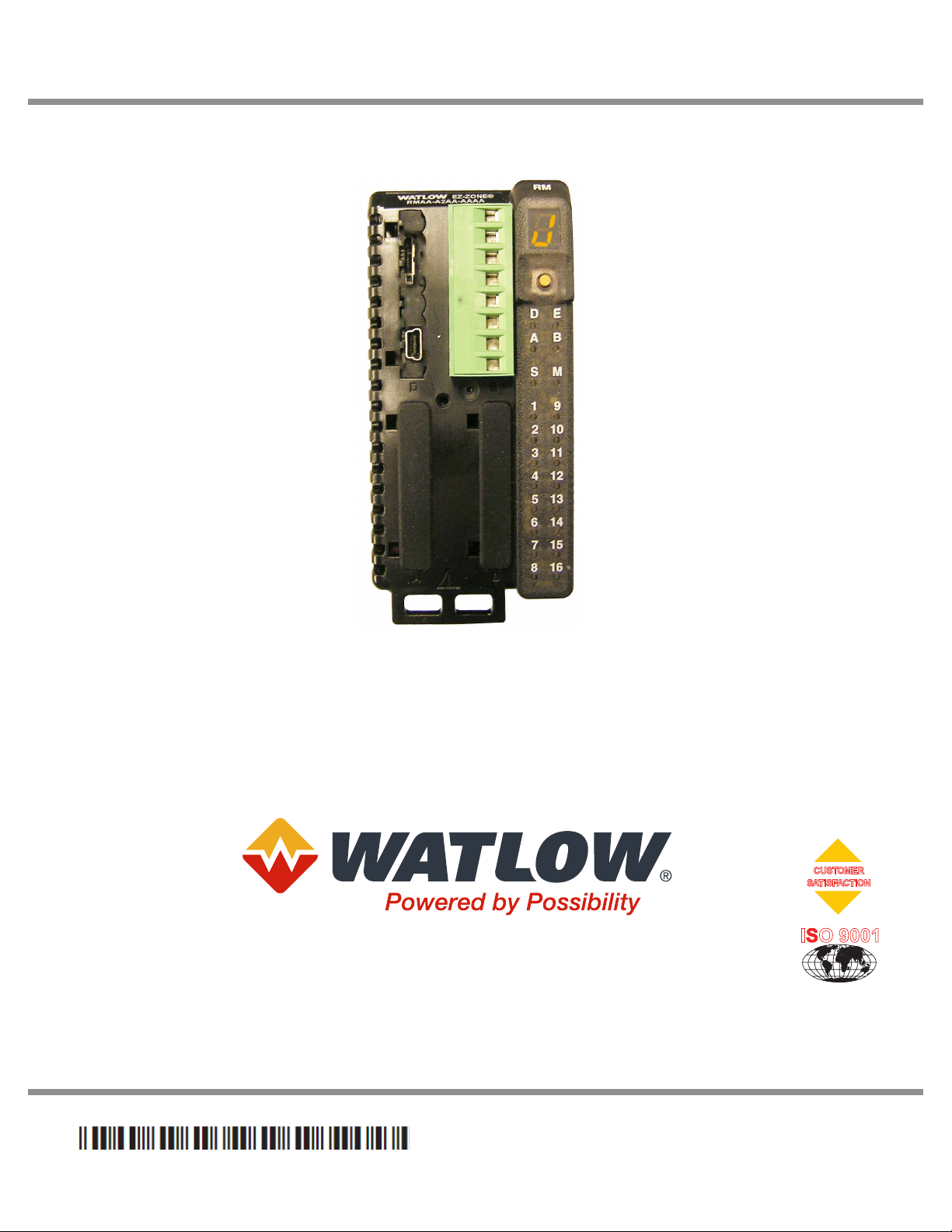
RM System Connected to a Programmable Logic Controller (PLC) on a DIN Rail
In this conguration, the PLC can be connected to the RM system via the RMA module using
one or more available protocols:
1. EtherNet/IP and or Modbus TCP
2. DeviceNet
3. Modbus RTU
4. Probus DP
Slot E
RM
RM
RM
Control
Expansion
Access
Slot CSlot CSlot C
Power
PLC
Supply
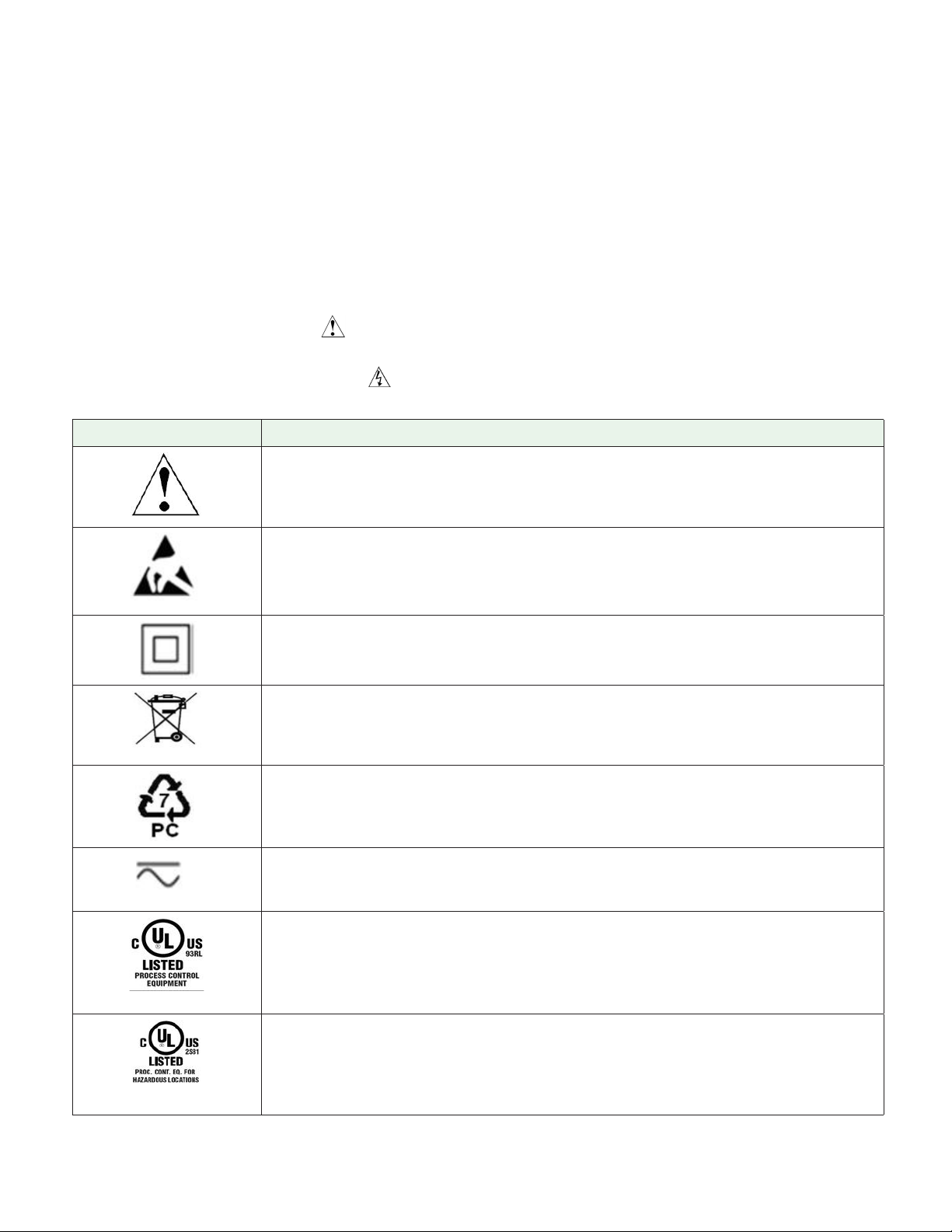
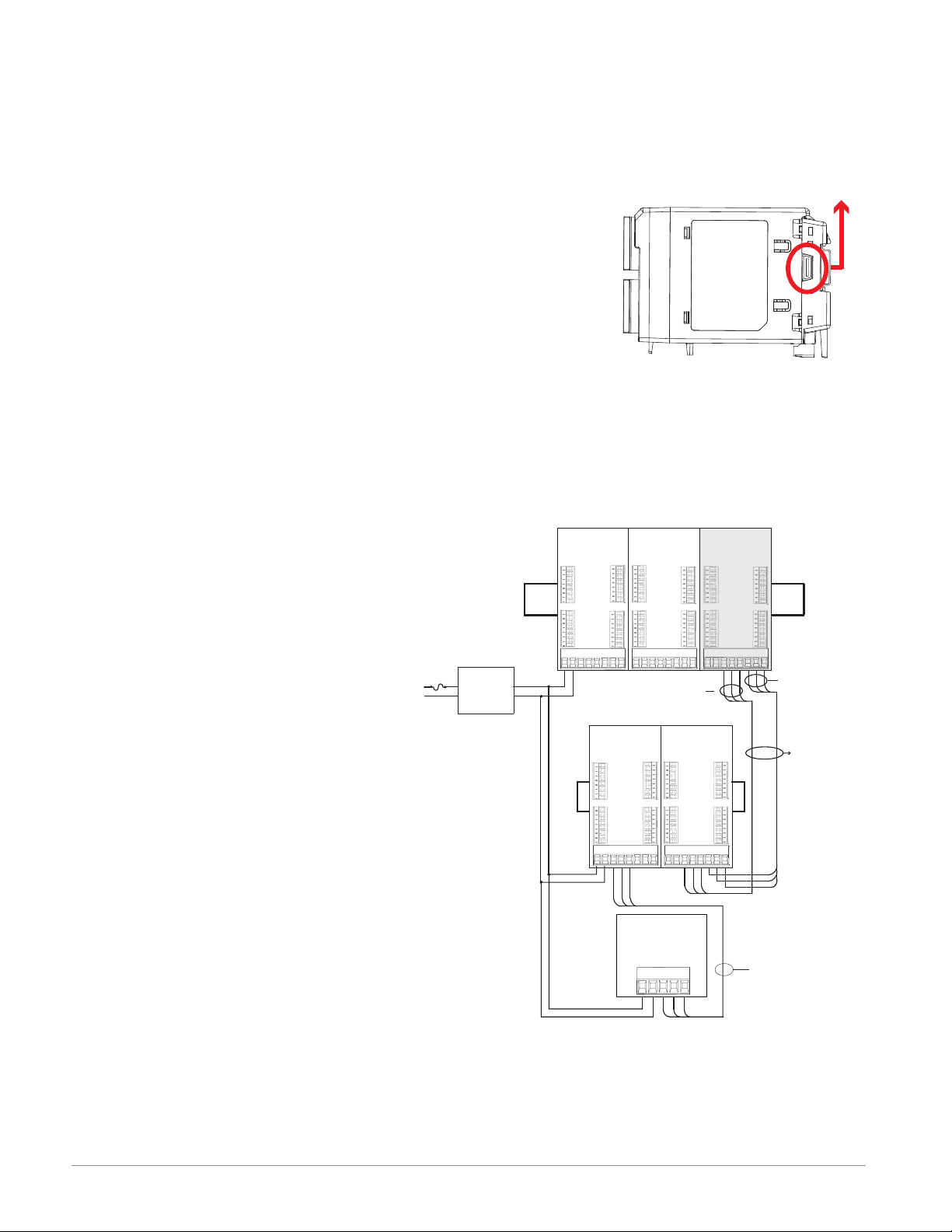
RM System Connected to a Split Rail with an Operator Interface Terminal (OIT)
In this conguration both the Inter-module Bus (backplane communications) and Standard
Bus are connected between rails to allow for remote capabilities. It is recommended that
the split rail connection not exceed 200 feet. In this conguration the OIT can communicate
with all modules (maximum 16 modules any combination with one Access module).
RM
Control
RM
Expansion
RM
Access
Slot E
Slot C
RM
Control
Slot C
Watlow EZ-ZONE® RMA Module • 7 • Chapter 1 Overview
RM
Expansion
Slot C
RM
Expansion
Slot C
Slot C
Slot C
Power
Supply
OIT
Page 12
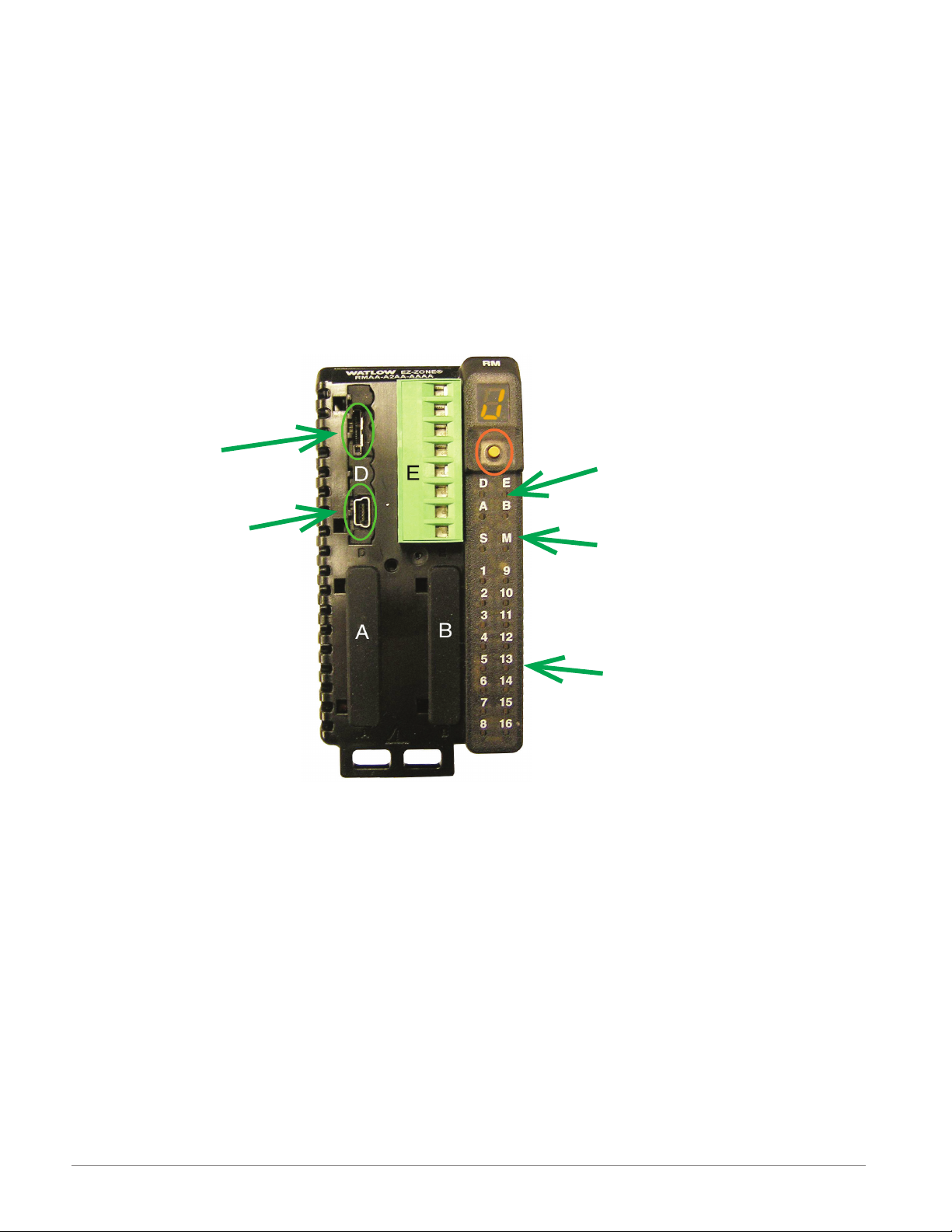
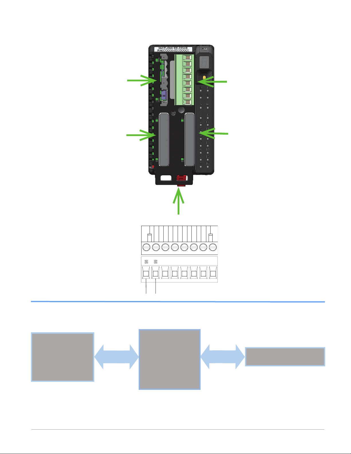
Module Orientation
The picture below reects a front view of an RMA module. Like all RM modules, there are
four slots that appear on the face (slot A, B, D, and E) of the module and one on the bottom
(slot C) not shown. For this particular module only slots D and E can be used. On the face of
the module there is a button (orange circle) under the Zone address J that when pushed and
held has the following function:
1. Push and hold for ~ 2 seconds to change the Zone address. Valid addresses range from 1
to 17 (1 - я, a is 10, b is 11, C is 12, d is 13, E is 14, f is 15, and h is 16). The Access
module is shipped (default factory address) at address J or 17
Note:
For correct operation and accuracy, the module must be mounted in a vertical orientation
as shown.
SD Card
USB, Mini Type B
connector
Module Status (Slot
A, B, D or E not used
on this module
Backplane protocol
(for this module always
set to Standard Busred)
Output indicators (1 to
16) not used on this
module.
Watlow EZ-ZONE® RMA Module • 8 • Chapter 1 Overview
Page 13
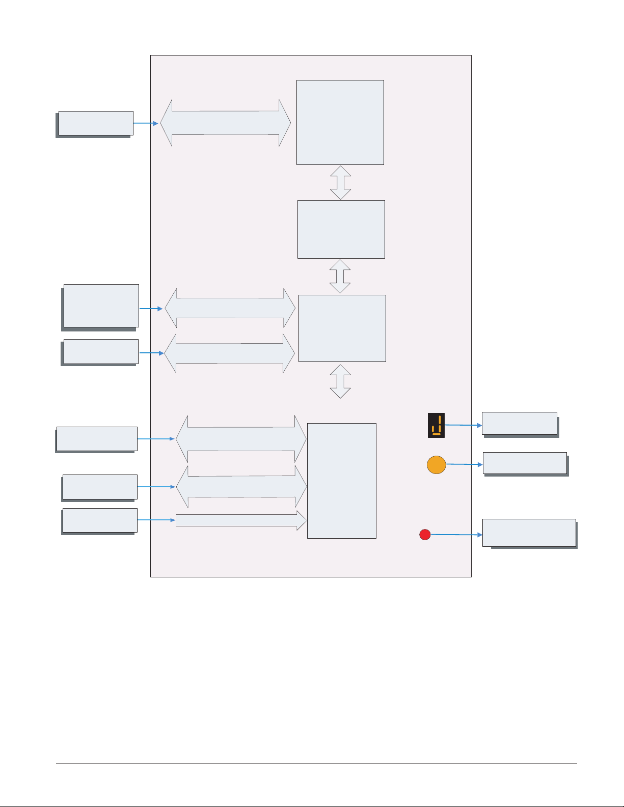
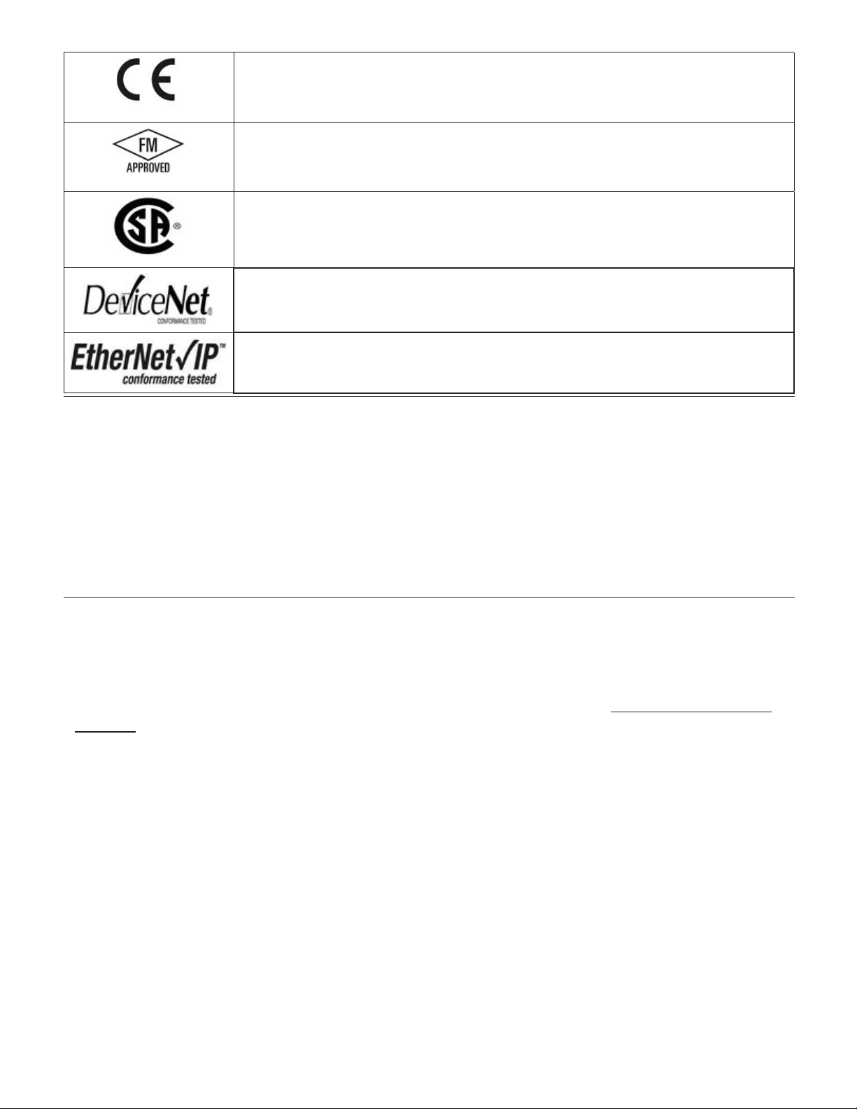
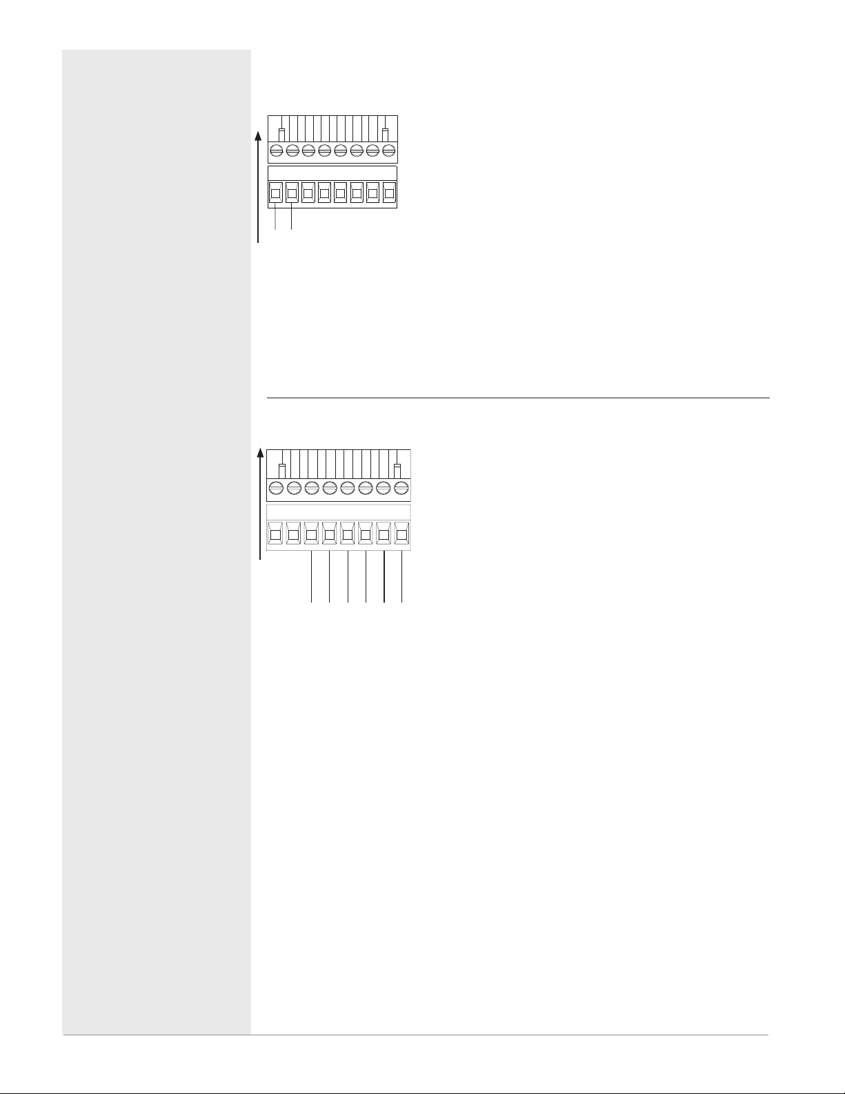
EZ-ZONE RM-Access Module - System Diagram
Input
Function
PLC, PC or OIT
Storage Device
(Configuration,
Memory and Data
Logging)
EIA - 232/485 or Ethernet
Fieldbus Protocol
Micro SD
Memory Socket
Output
Function
Protocol of Choice
- EtherNet/IP
- DeviceNet
- Modbus RTU
- Modbus TCP
- Profibus DP
Slot E
(optional)
Profile Ramp & Soak
Battery Backup &
Real Time Clock
(optional)
Auto Configuration,
Backup, USB Port
and Data Logging
PC
RUI, PC
Other RM Modules
Power Supply
Mini Type B USB Port v1.1
(as device only)
EIA - 485 Communications
Standard Bus
Inter-module Bus
20.4 to 30.8 Vac or Vdc
Slot D
(optional)
Standard Bus
Zone 1 - 17
Supervisory &
Power Board
Slot C
Zone Selection
Button
S
Indicates Zone
Address
Push to select Zone
Address
Indicates Standard Bus
communications activity
Watlow EZ-ZONE® RMA Module • 9 • Chapter 1 Overview
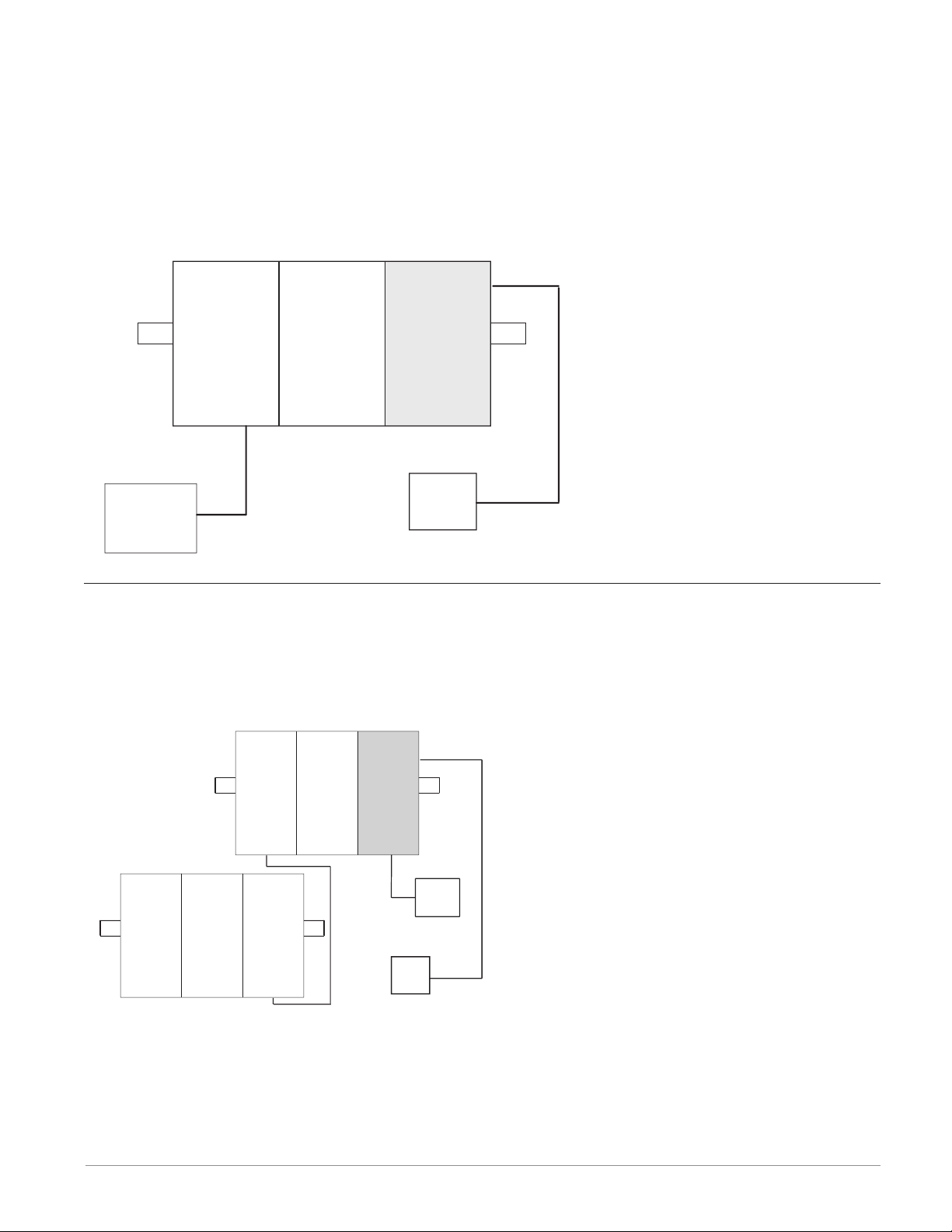
Page 14
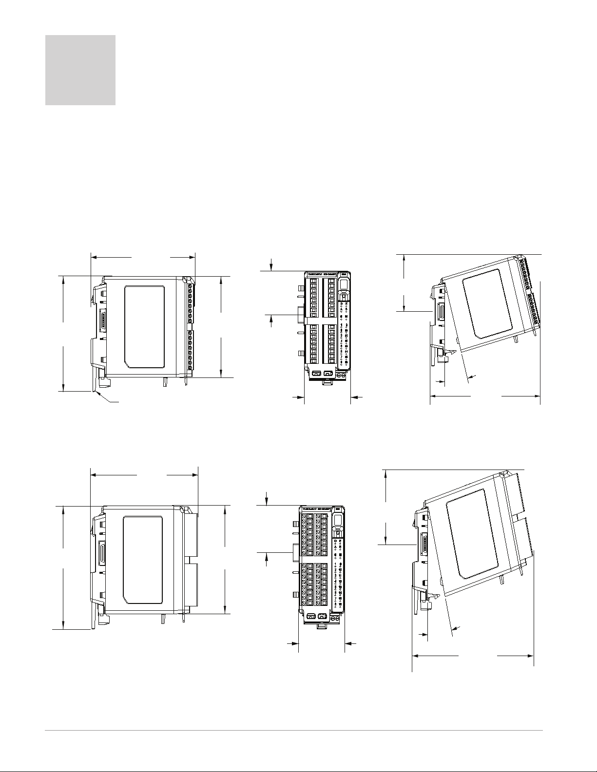
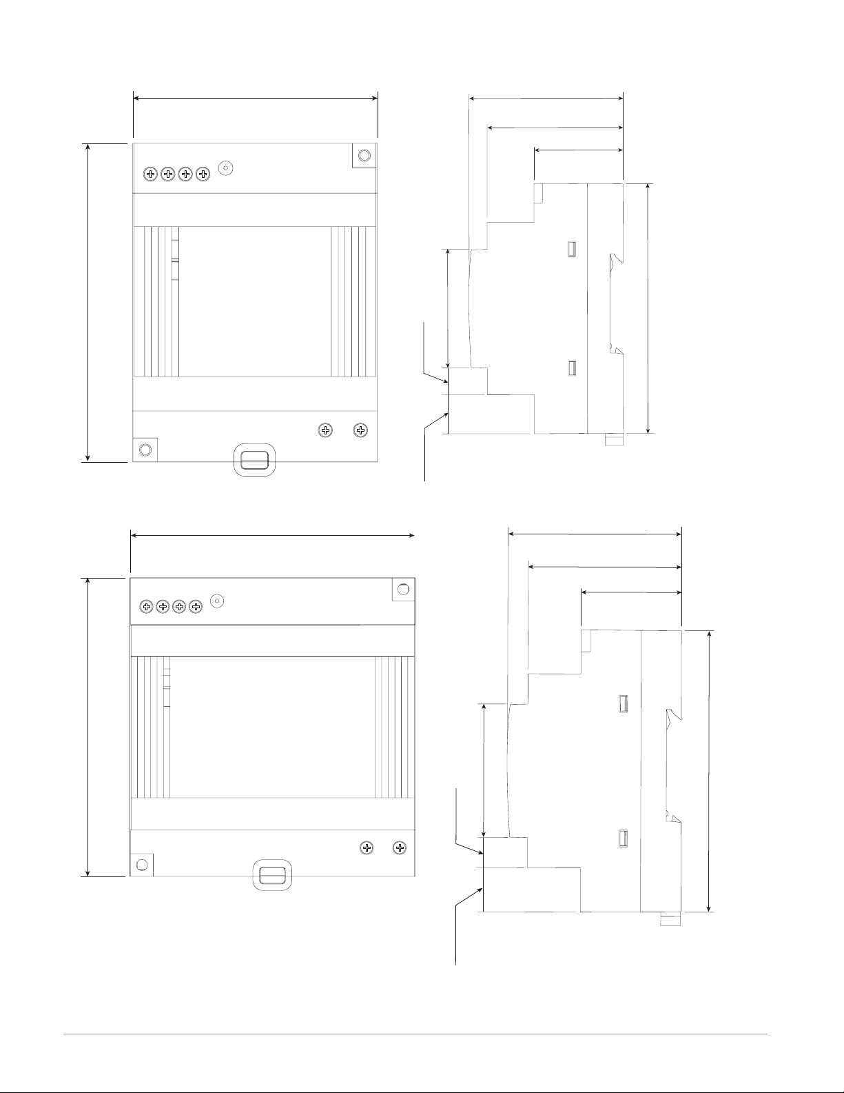
147.07 mm
( 5.8 in )
116.08 mm
( 4.57 in )
101.60 mm
( 4.00 in )
44.45 mm
( 1.75 in )
51.56 mm
( 2.03 in )
75.08 mm
( 3.0 in )
15
165 mm
( 6.50 in )
Module Removal Displacement
Latch in open position
155 mm
( 6.10 in )
116.08 mm
( 4.57 in )
101.60 mm
( 4.00 in )
44.45 mm
( 1.75 in )
51.56 mm
( 2.03 in )
75.08 mm
( 3.0 in )
15
°
173.90 mm
( 6.85 in )
Module Removal Displacement
2
Chapter 2: Install and Wire
Dimensions
As can be seen below the dimensions of the RM system will change slightly based on the type
of connector used.
Note:
Modules should always be mounted vertically. For easy removal and placement of modules
it is recommended that there be a 76.2 mm (3.00 in) clearance on the top, bottom and
front of each module.
Module Removal Clearance Standard Connectors
Module Removal Clearance Straight Connectors
Watlow EZ-ZONE® RMA Module • 10 • Chapter 2 Install and Wire
Page 15
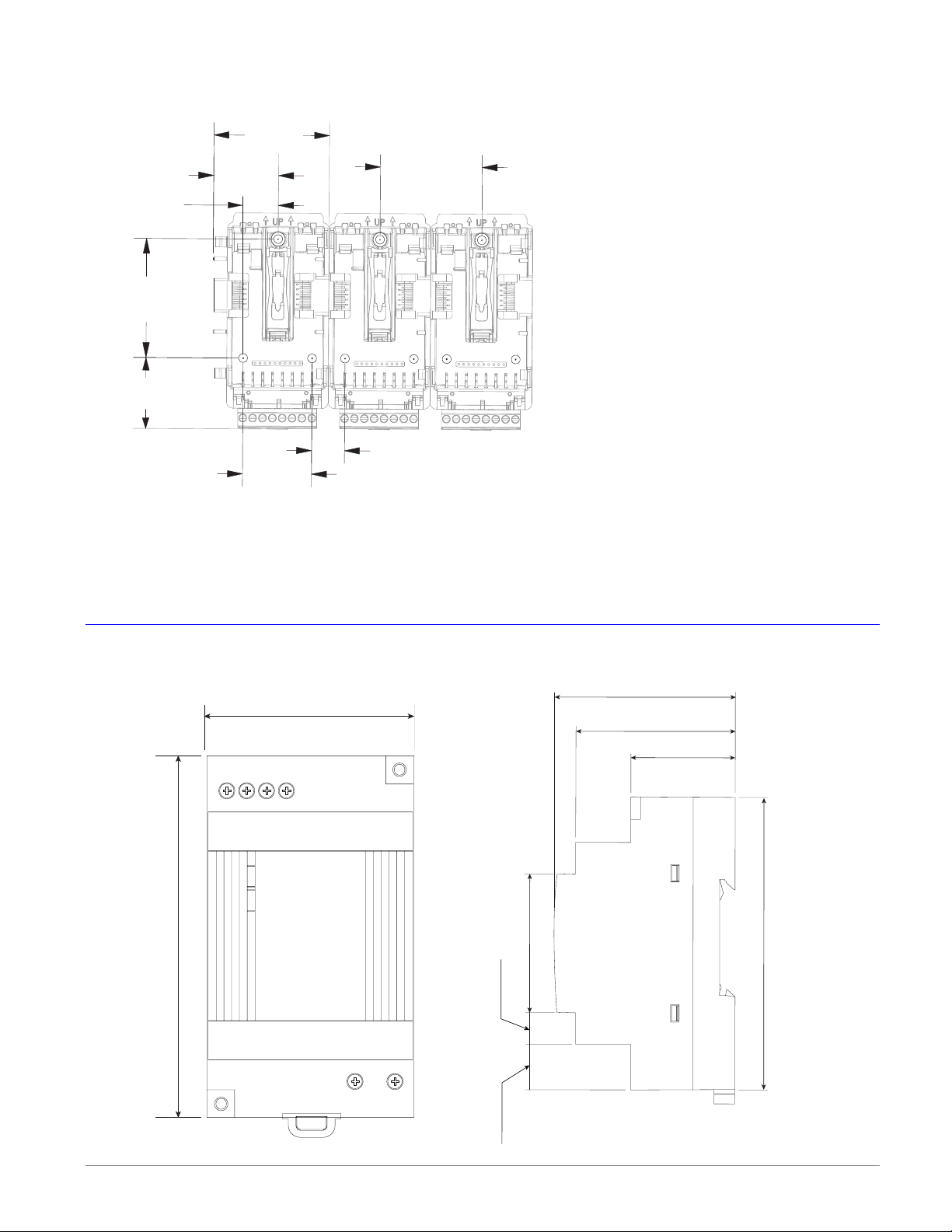
Dimensions (cont.)
56
53.00 mm
91.00 mm
14.20 mm
9.75 mm
55.6 mm
0.559 in
Chassis Mount Front View (Module Removed) - Screw Connection Pattern
58.67 mm
(2.31 in)
32.77 mm
(1.29 in)
17.53 mm
(.69 in)
60.45 mm
(2.38 in)
35.81 mm
(1.41 in)
35.05 mm
(1.38 in)
The view above is representative of the modular backplane without the module.
51.56 mm
(2.03 in)
16.76 mm
(.66 in)
Recommended chassis mount hardware:
1. #8 screw, 3/4" long
2. Torque to 10 -15 in-lb
3. No washers of any kind
Power Supplies
2.087 in
1234
-
++
-
DC LO
DC OK
DSP30
3.583 in
DSP 30
1.697 in
43.1 mm
49.00 mm
1.929 in
2.189 in
32.10 mm
1.264 in
3.583 in
91.00 mm
0.384 in
LN
Watlow EZ-ZONE® RMA Module • 11 • Chapter 2 Install and Wire
Page 16
DSP 60
56
71.00 mm
91.00 mm
14.20 mm
9.75 mm
55.6 mm
0.559 in
LN
56
89.9 mm
91.00 mm
14.20 mm
9.75 mm
56.8 mm
0.559 in
1234
++
3.583 in
-
-
DC LO
DC OK
2.795 in
vout ADJ.
DSP60
LN
DSP 100
1.697 in
43.1 mm
0.384 in
49.00 mm
1.929 in
2.189 in
32.10 mm
1.264 in
3.583 in
91.00 mm
1234
++
3.583 in
-
-
DC LO
DC OK
3.539 in
vout ADJ.
DSP100
1.697 in
43.1 mm
0.384 in
49.00 mm
1.929 in
2.236 in
32.10 mm
1.264 in
3.583 in
91.00 mm
Watlow EZ-ZONE® RMA Module • 12 • Chapter 2 Install and Wire
Page 17

Power Supply Specifications
DSP 30 DSP60 DSP100
AC Input Voltage Range VAC
Input Frequency Hz 47 - 63Hz
DC Input Voltage range VDC 120 - 370VDC
Inrush Current (115 / 230VAC) A 25 / 50A 30 / 60A 30 / 60A
Output Voltage Accuracy % ±1% of Nominal
Over voltage Protection V 120 - 145%
LED Indicators - - - - Green LED = On, Red LED = DC Output Low
Operating Temperature - - - -
Storage Temperature - - - - -25 to +85°C
Operating Humidity - - - - 20 - 95% RH (non condensing)
Vibration (Operating) - - - -
Safety Agency Approvals
90 - 264VAC, Class II double insulated (No ground
connection required)
-25 to +71°C (Derate linearly 2.5%/°C from 55 to
71°C)
IEC 60068-2-6 (Mounting by rail: Random wave,
10-500 Hz, 2G, ea. along X, Y, Z axes 10 min/
cycle, 60 min)
UL1310 Class 2(1), UL508 Listed, UL60950-1,
EN60950-1, CE
For a comprehensive listing of these specications point your browser to: http://us.tdk-
lambda.com/lp/products/dsp-series.htm
Watlow EZ-ZONE® RMA Module • 13 • Chapter 2 Install and Wire
Page 18
RM Installation and Removal on a DIN Rail
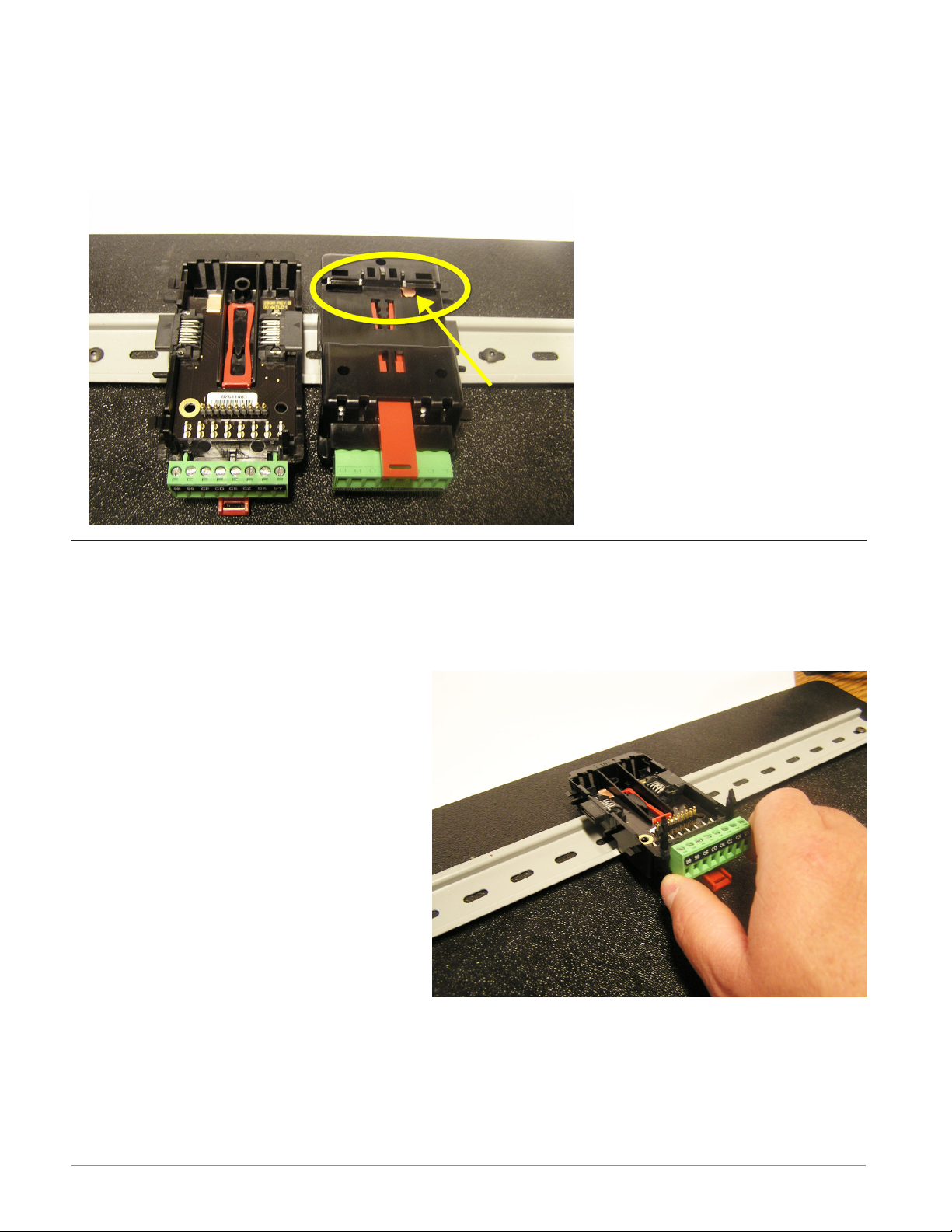
Modular Backplane Connector
The picture on the right shows the Modular Backplane Connector, both front and rear view.
The rear view is bringing in to focus a metal clip. If the DIN rail is grounded the Modular
Backplane Connector and the module connected to it will be also (recommended).
Installing the Modular Backplane Connector
To install the backplane follow the steps below:
1. Hook backplane assembly to upper edge of DIN rail, (see rear view above, backplane hook
detail that mates with upper rail edge is circled)
2. Next, rotate back plane assembly downward to engage the lower edge of the rail.
Note:
Din Rail clipping distance ranges from
1.366 -1.389 inches. The back plane
assembly will not latch onto the rail
successfully if the rail is out of dimension.
3. For nal positioning and locking, the
red tab is to be pushed upward to further engage the bottom edge of the
rail with an over center snap action
latch. (The red locking tab protrudes
from the bottom side of the back
plane assembly).
Note:
For easy removal and placement of modules it is recommended that there be a 76.2 mm
(3.00 in) clearance on the top, bottom and front of each module.
Watlow EZ-ZONE® RMA Module • 14 • Chapter 2 Install and Wire
Page 19
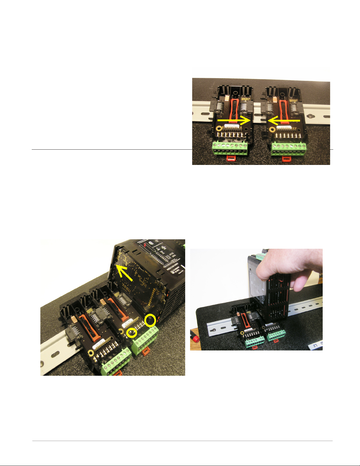
Installing Multiple Modular Backplane Connectors
Multiple modules are easily aligned and latched together. Each module includes matched
mating geometry that facilitates accurate and consistent interconnections.
To install backplane connectors follow the steps below:
1. Attach individual modules to the rail separately.
2. Laterally slide the modules together until
they touch.
3. When the multi-module system is attached
and laterally positioned to the desired placement the locking tab should be engaged to
secure the control system to the rail.
Module Installation
In the picture to the right notice that the arrow
is pointing at the top lip of the module (on side).
To install modules on the backplane follow the steps below:
1. Slide the lip of the module over the top of the Modular Backplane Connector and then
push down on the rear of the module. The module will then slide over the two posts just
above the green connector (see pictures below).
Watlow EZ-ZONE® RMA Module • 15 • Chapter 2 Install and Wire
Page 20
Wiring
Access Module (RMAx-Axxx-xxxx)
Slot A Slot B Slot D Slot E Terminal Function Configuration
Modbus RTU
- - -
- - -
- - -
- - -
- - -
- - -
- - -
- - -
- - -
- - -
- - -
- - -
- - -
- - -
- - -
- - -
- - -
- - -
- - -
- - -
- - -
- - -
- - -
- - -
- - -
- - -
- - -
- - -
- - -
- - -
- - -
- - -
- - -
- - -
- - -
- - -
- - -
- - -
- - -
- - -
- - -
- - -
- - -
- - -
- - -
- - -
- - -
- - -
- - -
- - -
- - -
- - -
- - -
- - -
- - -
- - -
- - -
- - -
- - -
- - -
- - -
- - -
- - -
- - -
- - -
- - -
- - -
- - -
- - -
- - -
- - -
- - -
- - -
- - -
- - -
- - -
- - -
- - -
- - -
- - -
- - -
- - -
- - -
- - -
- - -
- - -
- - -
- - -
- - -
- - -
- - -
- - -
- - -
- - -
- - -
- - -
CB
CA
CC
CB
CA
C5
C3
C2
E8
E7
E6
E5
E4
E3
E2
E1
V+
CH
SH
CL
V-
- - -
- - -
- - -
VP
B
A
DG
trB
B
A
trA
Modbus RTU EIA-485 T+/R+
Modbus RTU EIA-485 T-/RModbus RTU EIA-485 common
Modbus RTU EIA-485 T+/R+
Modbus RTU EIA-485 T-/RModbus RTU EIA-232 common
Modbus RTU EIA-232 DB9/pin 2
Modbus RTU EIA-232 DB9/pin 3
EtherNet/IP and Modbus TCP 10/100
EtherNet/IP™ and Modbus TCP unused
EtherNet/IP™ and Modbus TCP unused
EtherNet/IP™ and Modbus TCP receive EtherNet/IP™ and Modbus TCP unused
EtherNet/IP™ and Modbus TCP unused
EtherNet/IP™ and Modbus TCP receive +
EtherNet/IP™ and Modbus TCP transmit EtherNet/IP™ and Modbus TCP transmit +
DeviceNet
DeviceNet™ power
Positive side of DeviceNet™ bus
Shield interconnect
Negative side of DeviceNet™ bus
DeviceNet™ power return
Profibus DP
Voltage Potential
EIA-485 T+/R+
EIA-485 T-/RDigital ground (common)
Termination resistor B
EIA-485 T+/R+
EIA-485 T-/RTermination resistor A
Part # Digit 6
Slot E: RMAx-A(2)xx-xxxx
Part # Digit 6
Slot E: RMAx-A(3)xx-xxxx
Part # Digit 6
Slot E: RMAx-A(5)xx-xxxx
Part # Digit 6
Slot E: RMAx-A(6)xx-xxxx
Power & Standard Bus Communications
Slot C Terminal Function Configuration
98
99
CF
CD
CE
CZ
CX
CY
Watlow EZ-ZONE® RMA Module • 16 • Chapter 2 Install and Wire
Power input: ac or dc+
Power input: ac or dc-
Standard Bus EIA-485 common
Standard Bus EIA-485 T-/RStandard Bus EIA-485 T+/R+
Inter-module Bus
Inter-module Bus
Inter-module Bus
All
Standard Bus
Inter-module Bus
Page 21
RMA Module - Front View
Standard Connector
Slot D
Slot A
Slot E
Slot B
Slot C
Controller Power Supply
20.4 to 30.8VÎ (dc)
20.4 to 30.8VÅ (ac)
Safety Isolation
98
99
power
RMA Isolation Block
RMA
Low Voltage Power Bus
Low-voltage Isolation: 42V peak
Safety Isolation: 1,528VÅ (ac)
Low-voltage
Isolation
Communications Ports
Watlow EZ-ZONE® RMA Module • 17 • Chapter 2 Install and Wire
Page 22
Warning:
Use National Electric (NEC) or
other country-specific standard
wiring and safety practices when
wiring and connecting this controller to a power source and to
electrical sensors or peripheral
devices. Failure to do so may
result in damage to equipment
and property, and/or injury or
loss of life.
Note:
Maximum wire size termination
and torque rating:
• 0.0507 to 3.30 mm2 (30 to 12
• 0.56 Nm (5.0 in-lb.) torque
Note:
Adjacent terminals may be labeled differently, depending on
the model number
Note:
To prevent damage to the controller, do not connect wires to
unused terminals.
Note:
Maintain electrical isolation
between digital input-outputs,
switched dc/open collector
outputs and process outputs
prevent ground loops.
Note:
If the last two digits of the part
number are "12", this equipment
is suitable for use in CLASS I,
DIVISION 2, Groups A, B, C and
D or Non-Hazardous locations
only. Temperature Code T4
Warning:
Explosion Hazard – Substitution
of component may impair suitability for
Warning:
Explosion Hazard - Do not disconnect while the circuit is live
or unless the area is known to be
free of ignitable concentrations
of flammable substances.
ç
AWG) single-wire termination
or two 1.31 mm
2
(16 AWG)
.
to
ç
CLASS I, DIVISION 2.
ç
Access Module Wiring (RMAx-xxxx-xxxx)
Low Power
Slot C
99
98
power
Standard Bus EIA-485 Communications
Slot C
CE
CZ
CD
CF
Standard Bus
Common
Note:
Do not connect
unpowered USB
to EIA-485 converter. Communications may be
affected while
converter is not
connected to the
PC.
T- / R-
Common
T+ / R+
• 20.4 to 30.8 V Å (ac) / Î (dc) 9VA
• 47 to 63 Hz
• RMA module power consumption, 4 Watts
maximum
• 31 Watts maximum power available for P/S
part #:0847-0299-0000
• 60 Watts maximum power available for P/S
part #:0847-0300-0000
• 91 Watts maximum power available for P/S
part #:0847-0301-0000
• Class 2 or Safety Extra Low Voltage (SELV)
power source required to meet UL compliance standards
• CF, CD, CE - Standard Bus EIA485 Communications
• CZ, CX, CY - Inter-module Bus EIA485 Com-
CX
CY
munications
• Do not route network wires with power
Inter-module Bus
-
wires. Connect network wires in daisy-chain
+
fashion when connecting multiple devices in
a network
• Wire T-/R- to the A terminal of the EIA-485
port.
• Wire T+/R+ to the B terminal of the EIA-485
port.
• Wire common to the common terminal of
the EIA-485 port.
• Do not route network wires with power
wires. Connect network wires in daisy-chain
fashion when connecting multiple devices in
a network.
• A 120 Ω termination resistor may be required
across T+/R+ and T-/R-, placed on the last
controller on the network.
• Do not connect more than 16 EZ-ZONE RM
controllers on a network.
• Maximum network length: 1,200 meters
(4,000 feet)
• 1/8th unit load on EIA-485 bus
Watlow EZ-ZONE® RMA Module • 18 • Chapter 2 Install and Wire
Page 23
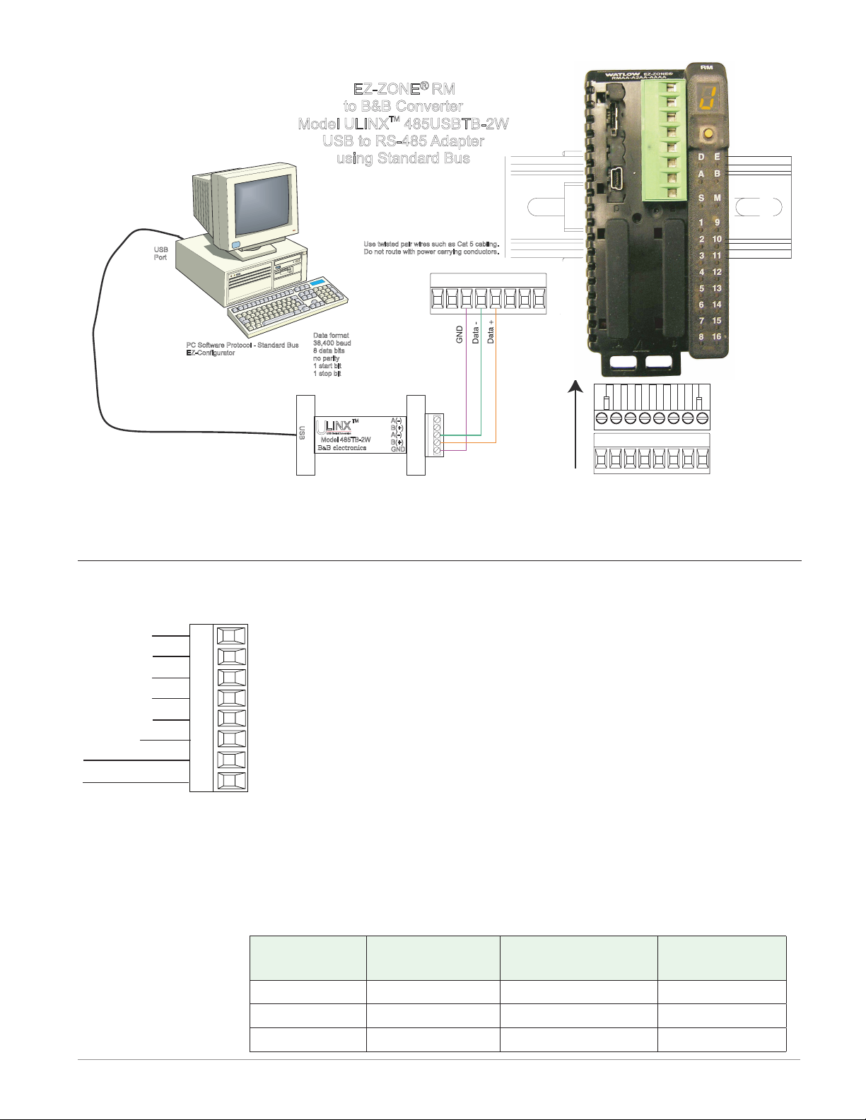
EZ-ZONE® RM
232 (Tx)
to B&B Converter
Model ULINX 485USBTB-2W
TM
USB to RS-485 Adapter
using Standard Bus
USB
Port
PC Software Protocol - Standard Bus
EZ-Configurator
Data format
38,400 baud
8 data bits
no parity
1 start bit
1 stop bit
U
S
U
B
Model 485TB-2W
B B electronics
Use twisted pair wires such as Cat 5 cabling.
Do not route with power carrying conductors.
TM
LINX
USB Serial Conversion
&
0847-0326-0000
A(-)
B(+)
A(-)
B(+)
GND
98 99
CF CD CE CZ CW CY
98 99
CF CD CE CZ CW CY
S
l
o
Note:
Do not connect USB to EIA-485 converter without power. Communications may be affected while converter is not connected to the PC.
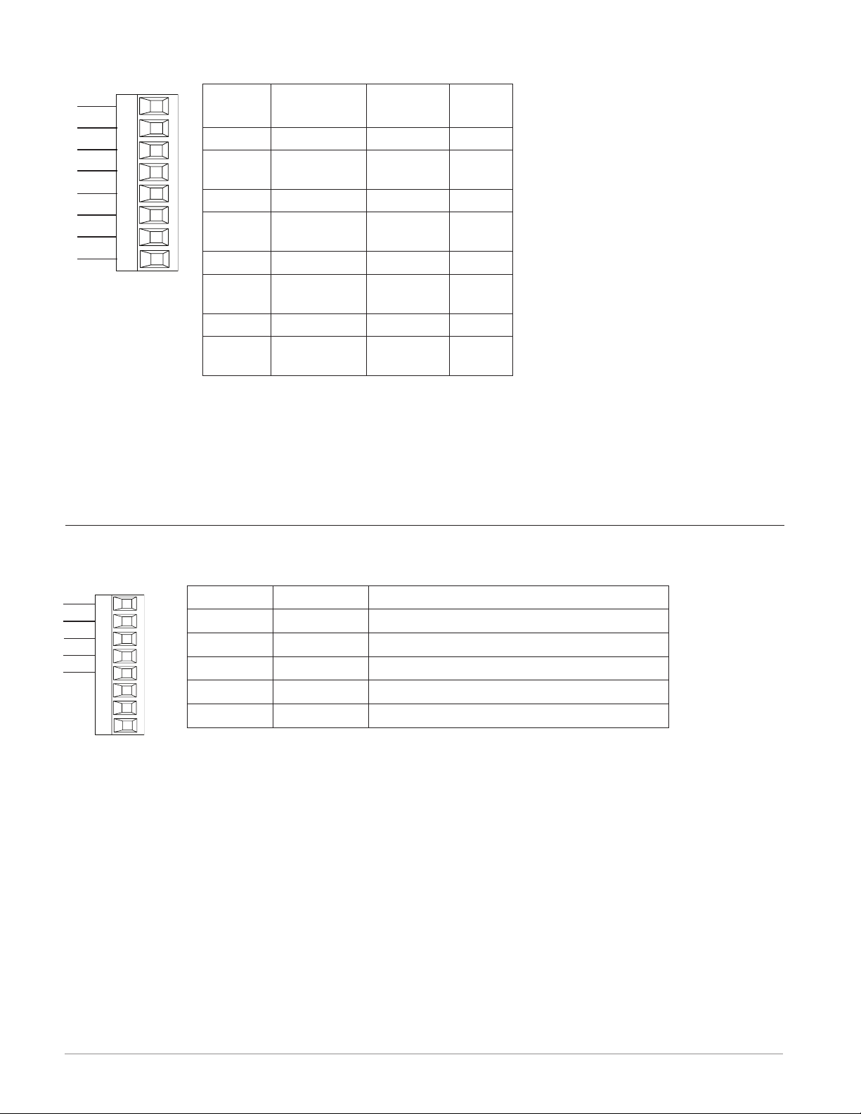
EIA-232/485 Modbus RTU Communications
• Wire T-/R- to the A terminal of
T+/R+
T-/R-
common
T+/R+
T-/R-
232 common
to DB9 pin 2 (RD)
232 (RD) to DB9 pin 3 (Tx)
Slot E
CB
CA
CC
CB
CA
C5
C3
C2
the EIA-485 port.
• Wire T+/R+ to the B terminal of
the EIA-485 port.
• Wire common to the common
terminal of the EIA-485 port.
• Do not route network wires with
power wires. Connect network
wires in daisy-chain fashion
when connecting multiple devices in a network.
• A termination resistor is re-
quired. Place a 120 Ω resistor
across T+/R+ and T-/R- of last
controller on network.
RMA Part # Digit 5 and 6 is A2
a Modbus network is 247.
• Maximum network length: 1,200
meters (4,000 feet)
• Maximum EIA-232 network
length: 15 meters (50 feet)
• Do not connect more than one
EZ-ZONE RM controller on an EIA232 network.
• Do not wire to both the EIA-485
and the EIA-232 pins at the same
time.
• Two EIA-485 terminals of T/R are
provided to assist in daisy-chain
wiring.
• 1/8th unit load on EIA-485 bus.
• Maximum number of devices on
t
C
Modbus-IDA
Terminal
EIA/TIA-485
Name
Watlow Terminal
Label
Function
DO A CA or CD T-/R-
D1 B CB or CE T+/R+
common common CC or CF common
Watlow EZ-ZONE® RMA Module • 19 • Chapter 2 Install and Wire
Page 24
Slot E
Slot E
EtherNet/IP™ and Modbus TCP Communications
RMA Part # Digit 5 and 6 is A3
unused
unused
receive -
unused
unused
receive +
transmit -
transmit +
E8
E7
E6
E5
E4
E3
E2
E1
RJ-45
pin
T568B wire
color
Signal Slot E
8 brown unused E8
7
brown and
white
unused E7
6 green receive - E6
5
white and
blue
unused E5
4 blue unused E4
3
white and
green
receive + E3
• Do not route network wires with
power wires.
• Connect one Ethernet cable per
controller to a 10/100 mbps Ethernet switch. Both Modbus TCP
and EtherNet/IP™ are available
on the network.
2 orange transmit - E2
1
white and
orange
transmit + E1
Notes:
EtherNet/IP™ and Modbus TCP communications to connect with a 10/100 switch.
Notes:
When using EtherNet/IP the RMA module supports implicit and unconnected explicit messaging.
DeviceNet™ Communications
V+
CAN_H
shield
CAN_L
V+
CH
SH
CL
V-
V-
T2
S2
R2
Terminal Signal Function
V+ V+ DeviceNet™ power
CH CAN_H Positive side of DeviceNet™ bus
SH shield Shield interconnect
CL CAN_L Negative side of DeviceNet™ bus
V- V- DeviceNet™ power return
RMA Part # Digit 5 and 6 is A5
Watlow EZ-ZONE® RMA Module • 20 • Chapter 2 Install and Wire
Page 25

Profibus DP Communications
Slot E
RMA Part # Digit 5 and 6 is A6
+5Vdc Voltage Potential
485 T+/R+
485 T-/R-
Digital ground
Ter mination resistor B
485 T+/R+
485 T-/R-
Ter mination resistor A
VP
DG
trB
trA
• Wire T-/R- to the A terminal of
B
A
the EIA-485 port.
• Wire T+/R+ to the B terminal of
the EIA-485 port.
• Wire Digital Ground to the com-
B
A
mon terminal of the EIA-485 port.
• Do not route network wires with
power wires. Connect network
wires in daisy-chain fashion when
connecting multiple devices in a
network.
• A termination resistor should be
used if this control is the last one
on the network.
• If external termination is to be
used with a 150 Ω cable place a
390 Ω resistor across pins VP and
B, a 220 Ω resistor across pins B
and A, and lastly, place a 390 Ω
resistor across pins DG and A.
• Do not connect more than 16 EZZONE RM modules on any given
segment.
• Maximum EIA-485 network
length: 1,200 meters (4,000 feet)
• 1/8th unit load on EIA-485 bus.
• Communications instance 2
• RMAX - A [6] X X - A A X X
• If using a 150 Ω cable Watlow
provides internal termination.
Place a jumper across pins trB
and B and trA and A.
Note:
When termination jumpers are in place, there is 392 ohm pull up resistor to 5V and 392 ohm pull down resistor to DP. There is also a 221
ohm resistor between A and B.
Profibus Terminal
EIA/TIA-485
Name
Watlow Termi-
nal Label
Function
VP (Voltage Potential) - - - - VP +5Vdc
B-Line B B T+/R+
A-Line A A T-/R-
DP-GND common DG common
Watlow EZ-ZONE® RMA Module • 21 • Chapter 2 Install and Wire
Page 26
Connecting and Wiring the Modules
Use twisted pair
sheilded wire for
RM System Connections
Components of a RM system can be installed as stand alone modules or can be interconnected on the DIN rail as shown below. When modules are connected together, power and communications are shared between modules over the modular backplane interconnection.
Therefore, bringing the necessary power and communications
wiring to any one connector in slot C is sufcient. The modular
backplane interconnect comes standard with every module
ordered and is generic in nature, meaning any of the RM modules shown below on the DIN rail can use it.
Notice in the split rail system diagram that a single power supply is being used across both DIN rails. One notable consideration when designing the hardware layout would be the available power supplied and the loading affect of all of the modules
used. Watlow provides three options for power supplies listed below:
1. 90-264 Vac to 24Vdc @ 31 watts (Part #: 0847-0299-0000)
2. 90-264 Vac to 24Vdc @ 60 watts (Part #: 0847-0300-0000)
3. 90-264 Vac to 24Vdc @ 91 watts (Part #: 0847-0301-0000)
With regards to the modular loading affect, maximum power for each is listed below:
1. RMCxxxxxxxxxxxx @ 7 watts
2. RMEx-xxxx-xxxx @ 7 watts
3. RMAx-xxxx-xxxx @ 4 watts
So, in the split rail system diagram, the
maximum current draw on the supply
would be 38 Watts.
- 2 RMC modules consumes 14W
- 2 RME modules consumes 14W
- 1 RMA module consumes 4W
- 1 Remote User Interface consumes 6W
With this power requirement the second
or third power supply could be used.
Another hardware conguration scenario
that could present itself (graphic not
shown) would be a conguration that re-
Low Voltage
Class 2
Power Supply
RM Controller
Module
RMCxxxxxxxxxAxx
Slot D
_
_
_
Standard Bus
_
_
Address 1
_
_
_
Slot A
_
_
_
_
_
_
_
_
Slot C
98 99 CFCECZ CX CY
CD
RM Controller
Module
RMCxxxxxxxxxAxx
Slot D
_
_
_
Standard Bus
_
_
Address 4
_
_
_
Slot A
_
_
_
_
_
_
_
_
98 99 CFCECZ CX CY
quires more than one supply. Lets make
some assumptions pertaining to the split
rail system diagram shown below. The
power supply used is the 91W supply.
The top DIN rail now has the following
modules:
- 2 RMC modules consumes 14W
- 1 RMA consumes 4W
- 11 RME modules consumes 77W
As can now be seen, the total power requirement exceeds 91W. In this case, another power
supply would be required. To incorporate another supply in this system simply disconnect
pins 99 and 98 on the remote DIN rail and connect another appropriately sized power supply
to those same pins.
Modular Backplane Interconnect
Slot E
_
_
_
_
_
_
_
_
Slot B
_
_
_
_
_
_
_
_
Standard Bus
Address 5
CD
RM Access
Module
Slot D
_
_
_
Standard Bus
_
_
Address 3
_
_
_
Slot A
_
_
_
_
_
_
_
_
98 99 CFCECZ CX CY
Slot E
Slot B
Slot C
CD
Slot C
CD
_
_
_
_
_
_
_
_
_
_
_
_
_
_
_
_
Slot E
Slot B
Standard Bus
RM Expansion
Module
RMEx-xxxx-xxxx RMAx-xxxx-xxxx
Slot D
Slot E
_
_
_
_
_
_
Standard Bus
_
_
_
_
Address 2
_
_
_
_
_
_
Slot A
Slot B
_
_
_
_
_
_
_
_
_
_
_
_
_
_
_
_
Slot C
98 99 CFCECZ CX CY
CD
Standard Bus
Split Rail Conguration
RM Expansion
Module
RMEx-xxxx-xxxx
Slot E
Slot D
_
_
_
_
_
_
_
_
_
_
_
_
_
_
_
_
Slot A
Slot B
_
_
_
_
_
_
_
_
_
_
_
_
_
_
_
Slot C
CD
_
98 99 CFCECZ CX CY
RUI
EZKB - _ A_ _-_ _ _ _
98
99 CF CE
_
_
_
_
_
_
_
_
_
_
_
_
_
_
_
_
Inter-module
Bus
each bus.
Watlow EZ-ZONE® RMA Module • 22 • Chapter 2 Install and Wire
Page 27
When using a split rail conguration ensure that the interconnections for the Inter-module
Bus and Standard Bus do not exceed 200 feet.
Note:
Module is not provided with a disconnect, use of an external disconnect is required. It
should be located in close proximity to the module and be labeled as the disconnect for
the module.
Note:
Connecting power supplies in parallel is not allowed. When power consumption is greater
than 91 watts use a split rail configuration.
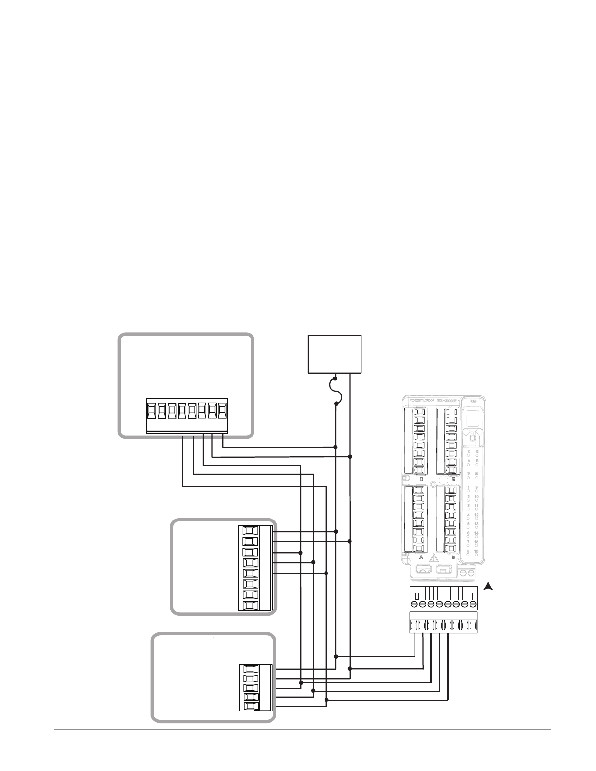
Wiring a Serial EIA-485 Network
Do not route network wires with power wires. Connect network wires in daisy-chain fashion when connecting multiple devices in a network. A termination resistor may be required.
Place a 120 Ω resistor across T+/R+ and T-/R- of the last con-troller on a on a network.
Note:
Termination resistors when used, require a termination resistor at both ends of the network.
A Network using Watlow's Standard Bus and an RUI/Gateway
EZ-ZONE ST
ST_ _ - (B or F) _ M _ -_ _ _ _
CD
CE
D5
D6
B5
CF
98
99
+ B
- A
power
power
common
EZ-ZONE PM
98
99
CF
CD
CE
B5
D6
D5
power
com
- A
+ B
Power
Supply
fuse
EZ-ZONE RM
t
C
l
o
S
98 99 CF CD CE CZ CX CY
RUI/Gateway
power
EZKB-_ A _ _- _ _ _ _
98
power
99
CF
CD
CE
common
- A
+ B
common
- A
+ B
Watlow EZ-ZONE® RMA Module • 23 • Chapter 2 Install and Wire
Page 28
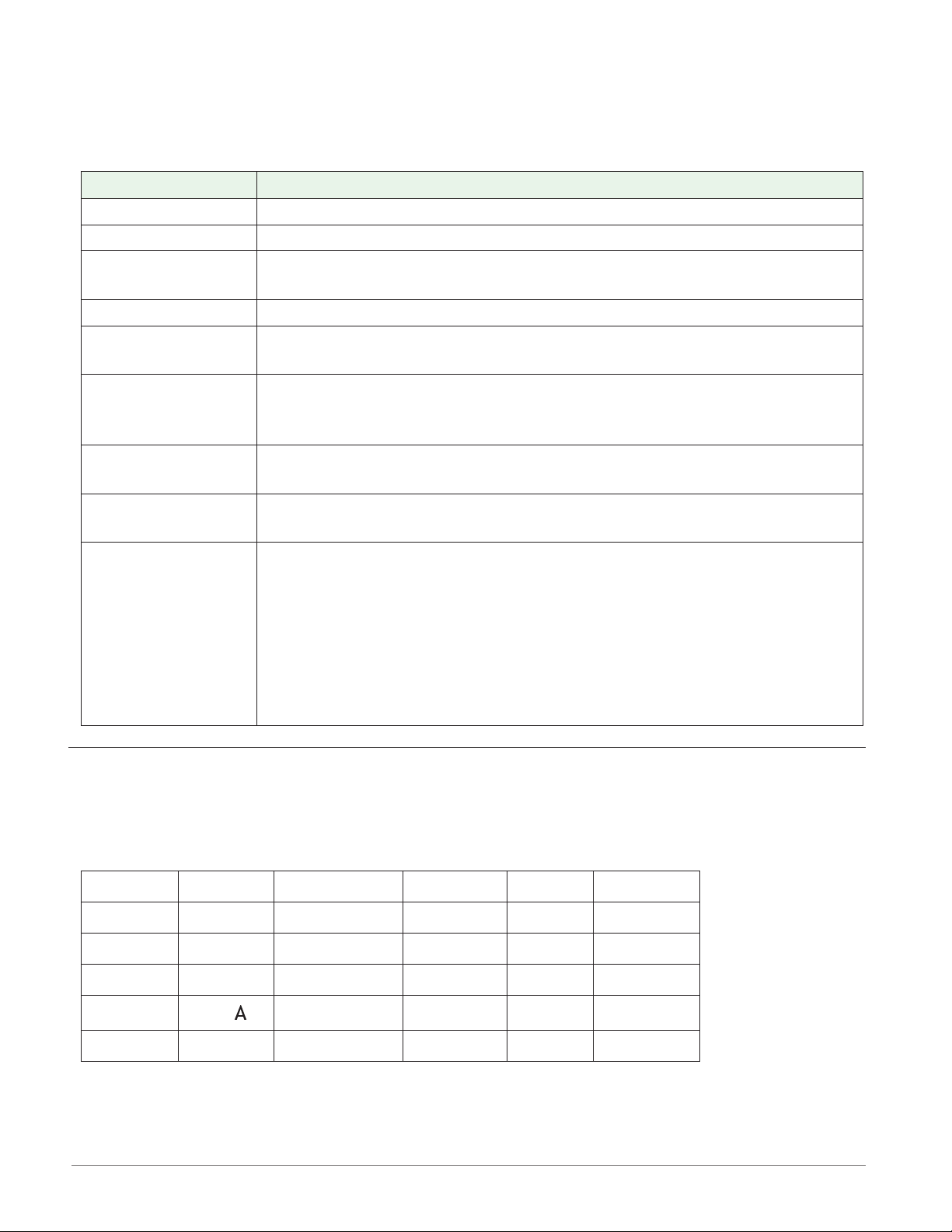
Conventions Used in the Menu Pages
To better understand the menu pages that follow review the naming conventions used. When
encountered throughout this document, the word "default" implies as shipped from the factory. Each page (Operations, Setup and Factory) and their associated menus have identical
headers dened below:
Header Name Definition
Display Visually displayed information from the control.
Parameter Name Describes the function of the given parameter.
Range
Default Values as delivered from the factory.
Modbus Relative
Address
CIP (Common Industrial Protocol)
Profibus Index
Parameter ID
Data Type and Access (R/W)
Defines options available for this prompt, i.e., min/max values (numerical), yes/no, etc... (further explanation below).
Identifies unique parameters using either the Modbus RTU or Modbus
TCP protocols (further explanation below).
If used in conjunction with an RMA module identifies unique parameters using either the DeviceNet or EtherNet/IP protocol (further explanation below).
If used in conjunction with an RMA module identifies unique parameters using Profibus DP protocol (further explanation below).
Identifies unique parameters used with other software such as, LabVIEW.
uint = Unsigned 16 bit integer
dint = Signed 32-bit, long
string = ASCII (8 bits per character)
float = IEEE 754 32-bit
RWES = Readable
Writable
EEPROM (saved)
User Set (saved)
Display
When a RM module is used in conjunction with the RUI (optional equipment) visual information from the module is displayed to the observer using a fairly standard 7 segment display.
Due to the use of this technology, several characters displayed need some interpretation, see
the list below:
1 = 1 ϯ = 7
, {= c i= i o= o u= u
щ
2 = 2 8 = 8 ц= d J= J P= P v= v
3 = 3 q = 9 E= E H= K q= q ФІ= W
4 = 4 0 = 0 F= F L= L r= r y= y
5 = 5 џ = g= g ЛЏ= M S= S Z= Z
6 = 6 Ѥ= b h= h n= n t= t
Watlow EZ-ZONE® RMA Module • 24 • Chapter 2 Install and Wire
Page 29

Range
Within this column notice that on occasion there will be numbers found within parenthesis.
This number represents the enumerated value for that particular selection. Range selections
can be made simply by writing the enumerated value of choice using any of the available
communications protocols. As an example, turn to the Setup Page and look at the Backup
Menu. To Save a conguration backup of all connected zones using Modbus simply right the
value of 1646 (save) to Modbus register 1270.
Communication Protocols
All RM modules come with the standard offering of Watlow's Standard Bus protocol used primarily for inter-module communications as well as for conguration using EZ-ZONE Congurator and Composer software (free download from Watlow's web site (http://www.watlow.
com). Along with Standard Bus, the RMH module can also be ordered with Modbus RTU (only
one protocol can be active at any given time). The RMA module has options for several different protocols listed below:
- Modbus RTU 232/485
- EtherNet/IP, Modbus TCP
- DeviceNet
- Probus DP
To learn more about any of the available RM modules, click on the link below. Once there
simply type in RM in the Keyword eld. http://www.watlow.com/literature/manuals.cfm
Modbus RTU Protocol
All Modbus registers are 16-bits and as displayed in this manual are relative addresses (actual). Some legacy software packages limit available Modbus registers to 40001 to 49999 (5
digits). Many applications today require access to all available Modbus registers which range
from 400001 to 465535 (6 digits).
Note:
In this User's Guide, all values shown representing Modbus addresses are added to 400,001
or 40,001 to acquire the absolute address.
For parameters listed as oat notice that only one (low order) of the two registers is listed,
this is true throughout this document. By default, the low order word contains the two low
bytes of the 32-bit parameter. As an example, look in the RMA Setup Page for the Analog pa-
rameter under the Variable menu. Find the column identied in the header as Modbus Relative Address, notice that it lists register 1034. Because this parameter is a oat it is actually
represented by registers 1034 (low order bytes) and 1035 (high order bytes). The Modbus
specication does not dictate which register should be high or low order so Watlow provides
the user the ability to swap this order (Setup Page, Communications Menu) from the default
low/high to high/low.
It should also be noted that some of the cells in the Modbus column contain wording pertaining to an offset. Several parameters in the RMA contain more than one instance; such as,
Data Log points (200), Gateway Instances (17), etc... The Modbus register shown always represents instance one. Take for an example the Log Point parameter found in the RMA Setup
Page under the Log Point menu. Instance one for the Source Function is shown as address
1470 and the offset to the next instance is identied as +16. If there was a desire to read or
write to instance 3, simply add 32 to 1470 to nd the appropriate address; in this case, Log
Point Source Function 3 address would be identied as 1502.
Watlow EZ-ZONE® RMA Module • 25 • Chapter 2 Install and Wire
Page 30

RMA _ - A [2, 3] _ _ - A A _ _
To learn more about the Modbus protocol point your browser to http://www.modbus.org.
Common Industrial Protocol (CIP)
DeviceNet & Ethernet/IP
Both DeviceNet and EtherNet/IP use open object based programming tools and are based on
the Common Industrial Protocol (CIP). Due to the use of CIP as the foundation of either protocol (DeviceNet or EtherNet/IP), they both use the same addressing scheme and parameter
addresses can be found in the column header identied as CIP. There you will nd the Class,
Instance and Attribute in hexadecimal, (decimal in parenthesis) for both protocols.
Note:
The RMA module equipped with EtherNet/IP supports implicit and unconnected explicit messages.
Data Types Used with CIP
uint = Unsigned 16 bit integer
int = Signed 16-bit
dint = Signed 32-bits, long
real = Float, IEEE 754 32-bit
string = ASCII, 8 bits per character
sint = Signed 8 bits , byte
RMA _ - A [3] _ _ - A A _ _
To learn more about the DeviceNet and EtherNet/IP protocol point your browser to http://
www.odva.org.
Profibus DP
To accommodate for Probus DP addressing the following menus contain a column identied
as Probus Index. Data types used in conjunction with Probus DP can be found in the table
below.
Data Types Used with Probus DP
word = Unsigned 16 bit
int = Signed 16-bit Integer
dint = Signed 32-bit Integer
real = Float, IEEE 754 32-bit
char = ASCII, 8 bits per character
byte = 8 bits
RMA _ - A [6] _ _ - A A _ _
To learn more about the Prbus DP protocol point your browser to http://www.probus.org
Watlow EZ-ZONE® RMA Module • 26 • Chapter 2 Install and Wire
Page 31

3
Chapter 3: Operations Page
Access Module Operation Page Parameters
To navigate to the Operations Page using the RUI, follow the steps below:
1. From the Home Page, press both the Up ¿ and Down ¯ keys for three seconds. Ai will ap-
pear in the upper display and oPEr will appear in the lower display.
2. Press the Up ¿ or Down ¯ key to view available menus.
3. Press the Advance Key ‰ to enter the menu of choice.
4. If a submenu exists (more than one instance), press the Up ¿ or Down ¯ key to select and
then press the Advance Key ‰ to enter.
5. Press the Up ¿ or Down ¯ key to move through available menu prompts.
6. Press the Infinity Key ˆ to move backwards through the levels: parameter to submenu, sub-
menu to menu, menu to Home Page.
7. Press and hold the Infinity Key ˆ for two seconds to return to the Home Page.
On the following pages, top level menus are identified with a yellow background color.
Note:
Some of these menus and parameters may not appear, depending on the controller's options. See model number information in the Appendix for more information. If there is
only one instance of a menu, no submenus will appear.
Note:
Some of the listed parameters may not be visible. Parameter visibility is dependent upon
controller part number.
dLog
oPEr Data Logging Menu
StAt Status
A.ЛЏE Available Logging Memory
A.ti Available Logging Time
bCUP
oPEr Backup Menu
StAt Status
2onE Zone
b.sta
oPEr Backup Status Menu
b.sta Backup (1 to 24)
StAt Status
Watlow EZ-ZONE® RMA Module • 27 • Chapter 3 Operations Page
Page 32

Dis-
playy
Parameter Name
Description
dLog
oPEr
Data Logging Menu
RM Access Module • Operations Page
Range Default
Modbus
Relative
Address
Class
Instance
Attribute
hex (dec)
CIP
Pro-
fibus
Index
Param-
eter
ID
Data
Type
& Read/
Write
*
Stat
Stat
A.ЛЏE
A.ME
A.ti
A.ti
* R: Read, W: Write, E: EEPROM, S: User Set
Data Logging
Status
Status indicates the
status of the data
logging function. OK
means logging can
be started or can
continue. No Memory
can indicate the
memory card is full
or not present.
Data Logging
Available Memory
Available logging
memory indicates
the remaining space
available for logging
in megabytes.
Data Logging
Available Logging
Time
Available Logging
Time when logging is
active, indicates the
remaining time that
logging can continue
in hours. When logging is not active,
indicates zero.
no.ЛЏ No Memory
(1637)
oH OK (138)
0 to 9,999 - - - - 1456 0x89 (137)
0 to 9,999 hours - - - - 1458 0x89 (137)
- - - - 1452 0x89 (137)
1
2
1
4
1
5
50 37002 uint
R
52 37004 uint
R
53 37005 uint
R
Watlow EZ-ZONE® RMA Module • 28 • Chapter 3 Operations Page
Page 33

RM Access Module • Operations Page
Display
Parameter Name
Description
Range Default
bCUP
oPEr
Backup Menu
Stat
Stat
2onE
ZonE
* R: Read, W: Write, E: EEPROM, S: User Set
Backup
Status
Status indicates the
status of the configuration backup function.
Off - means no backup or restore action
is running.
Save - indicates the
configuration of a
zone is being saved
to backup memory.
Restore - indicates a
saved configuration
is being restored to a
zone.
Monitor - When
backup is set to restore on a change
the RMA will check
to see if a module
serial number has
changed. If so, a restore will take place
for that module.
Complete - indicates
that the restoration
is complete.
Error - indicates
that the last action
failed.
Backup
Zone
Current Zone indicates which zone’s
configuration is being
saved or restored or
was last saved or restored.
oFF Off (62)
sauE Save (1644)
rEst Restore (1645)
ЛЏon Monitor
(1187)
CpLt Complete (18)
Err Error (28)
1 to 16 1 1276 0x8A
CIP
Modbus
Relative
Address
Off 1274 0x8A
Class
Instance
Attribute
hex (dec)
(138)
1 to 6
3
(138)
1 to 0x10
(16)
4
Pro-
fibus
Index
Param-
eter
ID
60 38003 uint
61 38004 uint
Data
Type
& Read/
Write
*
R
R
Watlow EZ-ZONE® RMA Module • 29 • Chapter 3 Operations Page
Page 34

RM Access Module • Operations Page
Display
Parameter Name
Description
Range Default
b.sta
oPEr
Backup Status Menu
Stat
Stat
* R: Read, W: Write, E: EEPROM, S: User Set
Backup
Status
Status indicates the
status of the current or most recent
backup function performed on the corresponding zone.
None - means no
backup or restore action is running.
OK - indicates the
zone was successfully
restored or saved
depending on the operation.
No Memory - indicates memory is full.
No Module - indicates that a previous
image for the module
had been saved but
while restoring the
module is no longer
present.
No Image - indicates
there is no backed up
image for a module
present on Standard
Bus.
Error - indicates
that the last action
failed.
nonE None (61)
oH OK (1644)
No.ЛЏ No Memory
(1637)
no.ЛЏ No Module
(1664)
no.Lg No Image
(1665)
Err Error (28)
Modbus
Relative
Address
None 1280
[offset 6]
CIP
Class
Instance
Attribute
hex (dec)
0x9A
(154)
1 to 0x18
(24)
1
Pro-
fibus
Index
Param-
eter
ID
94 54001 uint
Data
Type
& Read/
Write
*
R
Watlow EZ-ZONE® RMA Module • 30 • Chapter 3 Operations Page
Page 35

4
Chapter 4: Setup Pages
Access Module Setup Page Parameters
To navigate to the Setup Page using the RUI, follow the steps below:
1. From the Home Page, press and hold both the Up ¿ and Down ¯ keys for six seconds. Ai
will appear in the upper display and SEt will appear in the lower display.
Note:
If keys are released when opEr is displayed, press the Infinity Key ˆ or reset key to exit
and repeat until SEt is displayed.
2. Press the Up ¿ or Down ¯ key to view available menus.
3. Press the Advance Key ‰ to enter the menu of choice.
4. If a submenu exists (more than one instance), press the Up ¿ or Down ¯ key to select and
then press the Advance Key ‰ to enter.
5. Press the Up ¿ or Down ¯ key to move through available menu prompts.
6. Press the Infinity Key ˆ to move backwards through the levels: parameter to submenu, sub-
menu to menu, menu to Home Page.
7. Press and hold the Infinity Key ˆ for two seconds to return to the Home Page.
On the following pages, top level menus are identified with a yellow background color.
Note:
Some of these menus and parameters may not appear, depending on the controller's options. See model number information in the Appendix for more information. If there is
only one instance of a menu, no submenus will appear.
Note:
Some of the listed parameters may not be visible. Parameter visibility is dependent upon
controller part number.
gLbL
SEt Global Menu
d.prs Display Pairs (1 to
10)
Usr.s Save Settings As
Usr.r Restore Settings
From
COЛЏ
SEt Communications Menu
Ad.ЛЏ Modbus Address
bAUd Baud Rate
PAr Parity
ЛЏ.hL Modbus Word Order
iP.ЛЏ IP Address Mode
iP.F1 IP Fixed Address
Part 1
iP.F2 IP Fixed Address
Part 2
iP.F3 IP Fixed Address
Part 3
iP.F4 IP Fixed Address
Part 4
iP.S1 IP Fixed Subnet
Part 1
iP.S2 IP Fixed Subnet
Part 2
iP.S3 IP Fixed Subnet
Part 3
iP.S4 IP Fixed Subnet
Part 4
iP.g1 Fixed IP Gateway
Part 1
iP.g2 Fixed IP Gateway
Part 2
iP.g3 Fixed IP Gateway
Part 3
iP.g4 Fixed IP Gateway
Part 4
ЛЏb.E Modbus TCP Enable
EiP.E EtherNet/IP™ En-
able
Ad.d DeviceNet™ Node
Address
BAUd Baud Rate Device-
Net™
FC.E DeviceNet™ Quick
Connect Enable
P.add Profibus Address
A.LoC Profibus Address
Lock
stat Profibus Status
C_f Display Units
nu.s Non-volatile Save
Watlow EZ-ZONE® RMA Module • 31 • Chapter 4 Setup Page
Page 36

gtФІ
SEt Local Remote Gateway Menu
gtФІ Local Remote Gateway (1 to 17)
du.En Device Enabled
du.St Device Status
ЛЏ.oF Modbus Address Offset
oSt CIP Instance Offset
ao.nb CIP Implicit Assembly Output Mem-
ber Quantity
ai.nb CIP Implicit Assembly Input Member
Quantity
s.of Profibus Slot Offset
rtC
SEt Real Time Clock Menu
hoUr Hours
ЛЏin Minutes
ЛЏon Month
dAtE Date
yEAr Year
doФІ Day of Week
t.For Time Format
d.For Date Format
uAr
SEt Variable Menu
typE Data Type
Unit Units
dig Digital
AnLg Analog
Pro
SEt Profile Menu
Poti Power Off Time
dLog
SEt Data Logging Menu
PErd Period
f.act Full Action
Sfn.A Source Function A
Si.A Source Instance A
S2.A Source Zone A
Lg.pt
SEt Log Point Menu
Lg.pt Log Point (1 to 200)
SFn.A Source Function A
Si.A Source Instance A
S2.A Source Zone A
dEC Display Precision
bCUP
SEt Backup Menu
SAuE Save
rESt Restore
Watlow EZ-ZONE® RMA Module • 32 • Chapter 4 Setup Page
Page 37

RM Access Module • Setup Page
Display
gLbL
SEt
Global Menu
d.prs
dPrS
USr.S
USr.S
USr.r
USr.r
Global
Display Pairs
Defines the
number of Display Pairs.
Global
Save Settings
As
Save all of this
controller's
settings to the
selected set.
Global
Restore Settings From
Replace all of
this controller's settings
with another
set.
Parameter
name
Description
Modbus
Rela-
Range Default
1 to 10 1 - - - - 0x6A
nonE None (61)
- - - -
tive
Ad-
dress
26
SEt1 User Set 1 (101)
SEt2 User Set 2 (102)
nonE None (61)
- - - -
24
SEt1 User Set 1 (101)
SEt2 User Set 2 (102)
FCty Factory (31)
CIP
Class
Instance
Attribute
hex
(dec)
(103)
1
0x1C (28)
0x65
(101)
1
0x0E
(14)
0x65
(101)
1
0x0D
(13)
Data
Pro-
fibus
Index
- - - - 3028 uint
Pa-
ram-
eter
8 1014 uint
7 1013 uint
ID
Type
Read/
Write
RWES
RWE
RWE
&
*
CoЛЏ
SEt
Communications Menu
Ad.ЛЏ
Ad.M
bAUd
bAUd
* R: Read, W: Write, E: EEPROM, S: User Set
Communications
Modbus Address
Set the Modbus
address.
Communications
Baud Rate
Set the speed
of this controller's communications
to match the
speed of the
serial network.
1 to 247 1
9,600 (188)
19,200 (189)
38,400 (190)
9,600
432 0x96
(150)
2
1
434 0x96
(150)
2
3
76 17007 uint
RWE
74 17002 uint
RWE
Watlow EZ-ZONE® RMA Module • 33 • Chapter 4 Setup Page
Page 38

RM Access Module • Setup Page
Display
PAr
PAr
ЛЏ.hL
M.hL
iP.ЛЏ
iP.M
Parameter
name
Description
Communications
Parity
Set the parity
of this controller to match
the parity of
the serial network.
Communications
Modbus Word
Order
Select the
word order of
the two 16-bit
words in the
floating-point
values.
Communications
IP Address Mode
Select DHCP
to let a DHCP
server assign
an address to
this module.
Range Default
nonE None (61)
EuEn Even (191)
odd Odd (192)
hiLo Word High Low (1330)
Lohi Word Low High (1331)
dhCP DHCP (1281)
F.Add Fixed Address (1284)
None
Low
High
DHCP
Modbus
Rela-
tive
Ad-
dress
436 0x96
438 0x96
- - - - - - - - 77 17012 uint
CIP
Class
Instance
Attribute
hex
(dec)
(150)
2
4
(150)
2
5
Pro-
fibus
Index
75 17003 uint
80 17043 uint
Pa-
ram-
eter
ID
RWE
RWE
RWE
Data
Type
&
Read/
Write
*
Note:
Power to the
module must
be cycled after
changing the IP
address.
iP.F1
ip.F1
* R: Read, W: Write, E: EEPROM, S: User Set
Communications
IP Fixed Address Part 1
Set the IP address of this
module. Each
device on the
network must
have a unique
address.
0 to 255 169
- - - - - - - - - - - - 17014 uint
RWE
Watlow EZ-ZONE® RMA Module • 34 • Chapter 4 Setup Page
Page 39

RM Access Module • Setup Page
Display
iP.F2
ip.F2
iP.F3
ip.F3
iP.F4
ip.F4
iP.S1
ip.S1
iP.S2
ip.S2
iP.S3
ip.S3
Parameter
name
Description
Communications
IP Fixed Address Part 2
Set the IP address of this
module. Each
device on the
network must
have a unique
address.
Communications
IP Fixed Address Part 3
Set the IP address of this
module. Each
device on the
network must
have a unique
address.
Communications
IP Fixed Address Part 4
Set the IP address of this
module. Each
device on the
network must
have a unique
address.
Communications
IP Fixed Subnet
Part 1
Set the IP subnet mask for
this module.
Communications
IP Fixed Subnet
Part 2
Set the IP subnet mask for
this module.
Communications
IP Fixed Subnet
Part 3
Set the IP subnet mask for
this module.
Range Default
0 to 255 254
0 to 255 1
0 to 255 1
0 to 255 255
0 to 255 255
0 to 255 0
Modbus
Rela-
tive
Ad-
dress
- - - - - - - - - - - - 17015 uint
- - - - - - - - - - - - 17016 uint
- - - - - - - - - - - - 17017 uint
- - - - - - - - - - - - 17020 uint
- - - - - - - - - - - - 17021 uint
- - - - - - - - - - - - 17022 uint
CIP
Class
Instance
Attribute
hex
(dec)
Pro-
fibus
Index
Pa-
ram-
eter
ID
Data
Type
&
Read/
Write
*
RWE
RWE
RWE
RWE
RWE
RWE
* R: Read, W: Write, E: EEPROM, S: User Set
Watlow EZ-ZONE® RMA Module • 35 • Chapter 4 Setup Page
Page 40

RM Access Module • Setup Page
Display
iP.S4
ip.S4
iP.g1
ip.g1
iP.g2
ip.g2
iP.g3
ip.g3
Parameter
name
Description
Communications
IP Fixed Subnet
Part 4
Set the IP subnet mask for
this module.
Communications
Fixed IP Gateway Part 1
Communications
Fixed IP Gateway Part 2
Communications
Fixed IP Gateway Part 3
Range Default
0 to 255 0
0 to 255 0
0 to 255 0
0 to 255 0
Modbus
Rela-
tive
Ad-
dress
- - - - - - - - - - - - 17023 uint
- - - - - - - - - - - - 17026 uint
- - - - - - - - - - - - 17027 uint
- - - - - - - - - - - - 17028 uint
CIP
Class
Instance
Attribute
hex
(dec)
Pro-
fibus
Index
Pa-
ram-
eter
ID
RWE
RWE
RWE
RWE
Data
Type
&
Read/
Write
*
iP.g4
ip.g4
ЛЏb.E
Mb.E
EiP.E
EiP.E
Ad.d
Ad.d
* R: Read, W: Write, E: EEPROM, S: User Set
Communications
Fixed IP Gateway Part 4
Communications
Modbus TCP Enable
Activate Modbus TCP.
Communications
EtherNet/IP™
Enable
Activate Ethernet/IP™.
Communications
DeviceNet™
Node Address
Set the DeviceNet™ address for this
gateway.
0 to 255 0
no No (59)
yES Yes (106)
no No (59)
yES Yes (106)
0 to 63
Yes
Yes
63
- - - - - - - - - - - - 17029 uint
RWE
- - - - - - - - 78 17041 uint
RWE
- - - - - - - - 79 17042 uint
RWE
- - - - - - - - 83 17052 uint
RWE
Watlow EZ-ZONE® RMA Module • 36 • Chapter 4 Setup Page
Page 41

RM Access Module • Setup Page
Display
bAUd
bAUd
FC.E
FC.E
p.add
P.Add
a.Loc
A.Loc
stat
Stat
Parameter
name
Description
Communications
DeviceNet™
Baud Rate
Set the speed
of this gateway's communications
to match the
speed of the
serial network.
Communications
DeviceNet™
Quick Connect
Enable
Allows for immediate communication
with the scanner upon power
up.
Communications
Profibus DP Address
Set the Profibus address for
this gateway.
Communications
Profibus Address Lock
When set to
yes the Profibus address
cannot be
changed using
software. Can
be changed
from the optional RUI.
Communications
Profibus DP
Status
Current Profibus status.
Range Default
125 125 kb
250 250 kb
500 500 kb
no No (59)
yES Yes (106)
0 to 126
no No (59)
yEs Yes (106)
rEdy Ready (1662)
rng Running (149)
125
No
126
No
- - - -
Modbus
Rela-
tive
Ad-
dress
- - - - - - - - 84 17053 uint
- - - - - - - - - - - - 17054 uint
- - - - - - - - - - - - 17060 uint
- - - - - - - - - - - - 17061 uint
- - - - - - - - - - - - 17062 uint
CIP
Class
Instance
Attribute
hex
(dec)
Pro-
fibus
Index
Pa-
ram-
eter
ID
Data
Type
&
Read/
Write
*
RWE
RWE
RWE
RWE
R
* R: Read, W: Write, E: EEPROM, S: User Set
Watlow EZ-ZONE® RMA Module • 37 • Chapter 4 Setup Page
Page 42

RM Access Module • Setup Page
Display
C_F
C_F
nU.S
nU.S
Parameter
name
Description
Communications
Display Units
Select which
scale to use for
temperature
passed over
communications port 2.
Communications
Non-volatile
Save
If set to Yes all
values written
to the control
will be saved in
EEPROM after
approximately
3 seconds.
f F (30)
C C (15)
no No (59)
yES Yes (106)
Range Default
F 440
Yes 444 0x96
Modbus
Rela-
tive
Ad-
dress
CIP
Class
Instance
Attribute
hex
(dec)
0x96
(150)
2
6
(150)
2
8
Pro-
fibus
Index
81 17050 uint
82 17051 uint
Pa-
ram-
eter
ID
Data
Type
&
Read/
Write
*
RWE
RWE
Note:
The EEPROM
allows for approximately
one million
writes.
gtФІ
SEt
Local Remote Gateway Menu
du.En
du.En
du.St
du.St
Local Remote
Gateway (1 to
17)
Device Enabled
When set to
yes the gateway attempts
to establish
a connection
with the specified control.
Local Remote
Gateway (1 to
17)
Device Status
Indicates
whether or not
a valid connection is made.
no No (59)
yES Yes (106)
oFF Off (62)
on On (63)
No
- - - -
452
{offset
20}
460
{offset
20}
0x7C
(124)
1 to 11
(17)
2
0x7C
(124)
1 to 11
(17)
6
23 24002 uint
RWE
- - - - 24006 uint
R
* R: Read, W: Write, E: EEPROM, S: User Set
Watlow EZ-ZONE® RMA Module • 38 • Chapter 4 Setup Page
Page 43

RM Access Module • Setup Page
Display
ЛЏ.oF
M.oF
oSt
oSt
Ao.nb
Ao.nb
Parameter
name
Description
Local Remote
Gateway (1 to
17)
Modbus Address
Offset
When multiple
EZ-ZONE controllers are
used over Modbus the value
entered allows
for parameter
differentiation
from control to
the next.
Local Remote
Gateway (1 to
17)
CIP Instance
Offset
When executing explicit
messages with
multiple EZZONE controllers the number entered
allows for
differentiation
from control to
control.
Gateway (1 to
17)
CIP Implicit Assembly Output
Member Quantity
The number
entered determines the size
of the output
(produced) assembly.
0 to 65,535
0 to 255
0 to 40
Range Default
0
0
- - - -
Modbus
Rela-
tive
Ad-
dress
454
{offset
20}
456
{offset
20}
466
{offset
20}
CIP
Class
Instance
Attribute
hex
(dec)
0x7C
(124)
1 to 11
(17)
3
0x7C
(124)
1 to 11
(17)
4
0x7C
(124)
1 to 11
(17)
9
Pro-
fibus
Index
24 24003 uint
25 24004 uint
26 24009 uint
Pa-
ram-
eter
ID
Data
Type
&
Read/
Write
*
RWE
RWE
RWE
* R: Read, W: Write, E: EEPROM, S: User Set
Watlow EZ-ZONE® RMA Module • 39 • Chapter 4 Setup Page
Page 44

RM Access Module • Setup Page
Display
Ai.nb
Ai.nb
s.of
S.of
Parameter
name
Description
Gateway (1 to
17)
CIP Implicit Assembly Input
Member Quantity
The number
entered determines the size
of the input
(consumed) assembly.
Gateway (1 to
17)
Profibus DP Slot
Offset
Set Profibus instance member
offset for this
Standard Bus
controller.
0 to 40
0 to 254
Range Default
- - - -
Instance
1 = 0
Instance
2 = 20
Instance
3 = 40
Instance
4 = 60
Instance
5 = 80
Instance
6 = 100
Instance
7 = 120
Instance
8 = 140
Instance
9 = 160
Instance
10 = 180
Instance
11 = 200
Instance
12 = 220
Instance
13 = 240
Instance
14 = 0
Instance
15 = 0
Instance
16 = 0
Instance
17 = 0
Modbus
Rela-
tive
Ad-
dress
468
{offset
20}
- - - - 0x7C
CIP
Class
Instance
Attribute
hex
(dec)
0x7C
(124)
1 to 11
(17)
0x0A
(10)
(124)
1 to 11
(17)
0x0B
(11)
Pro-
fibus
Index
27 24010 uint
28 24011 uint
Pa-
ram-
eter
ID
Data
Type
&
Read/
Write
*
RWE
RWE
* R: Read, W: Write, E: EEPROM, S: User Set
Watlow EZ-ZONE® RMA Module • 40 • Chapter 4 Setup Page
Page 45

RM Access Module • Setup Page
Parameter
Display
name
Description
rtC
SEt
Real Time Clock Menu
hoUr
hoUr
ЛЏin
Min
ЛЏon
Mon
dAtE
dAtE
yEAr
YEAr
doФІ
doW
Real Time Clock
Hours
Set hours for
the Real Time
Clock (0 = midnight)
Real Time Clock
Minutes
Set minutes for
the Real Time
Clock.
Real Time Clock
Month
Set current
month for the
Real Time
Clock.
Real Time Clock
Date
Set the current date for
the Real Time
Clock.
Real Time Clock
Year
Set the current year for
the Real Time
Clock.
Real Time Clock
Day of Week
Set the current day of
the week for
the Real Time
Clock.
Range Default
0 to 23 - - - -
0 to 59 - - - -
1 to 12 - - - -
1 to 31 - - - -
2008 to 2100 - - - -
sun Sunday (1565)
- - - -
ЛЏon Monday (1559)
tuE Tuesday (1560)
ФІEd Wednesday (1561)
thUr Thursday (1562)
Fri Friday (1563)
Sat Saturday (1564)
Modbus
Rela-
tive
Ad-
dress
1428 0x88
1430 0x88
1434 0x88
1436 0x88
1438 0x88
1426 0x88
CIP
Class
Instance
Attribute
hex
(dec)
(136)
(136)
(136)
(136)
(136)
(136)
Data
Pro-
fibus
Index
35 36003 uint
1
3
36 36004 uint
1
4
38 36006 uint
1
6
39 36010 uint
1
7
40 36008 uint
1
8
34 36007 uint
1
2
Pa-
ram-
eter
ID
Type
&
Read/
Write
*
RW
RW
RW
RW
RW
RW
* R: Read, W: Write, E: EEPROM, S: User Set
Watlow EZ-ZONE® RMA Module • 41 • Chapter 4 Setup Page
Page 46

RM Access Module • Setup Page
Display
t.For
t.For
d.For
d.For
Parameter
name
Description
Real Time Clock
Time Format
Use Time Format to select
whether time
of day is indicated in the
data log in
hours minutes
and seconds
HH:MM:SS or
simply hours
and minutes
HH:MM.
Real Time Clock
Date Format
Use Date Format to select
whether dates
in the data log
are recorded
with month
before day
MM/DD/YYYY
or day before
month DD/MM/
YYYY.
Range Default
HH:MM (1629)
HH:MM:SS (1630)
MM/DD/YYYY (1631)
DD/MM/YYYY (1632)
HH:MM
MM/DD/
YYYY
Modbus
Rela-
tive
Ad-
dress
1444 0x88
1446 0x88
CIP
Class
Instance
Attribute
hex
(dec)
(136)
0x0B
(11)
(136)
0x0C
(12)
Data
Pro-
fibus
Index
43 36011 uint
1
44 36012 uint
1
Pa-
ram-
eter
ID
Type
&
Read/
Write
*
RW
RW
* R: Read, W: Write, E: EEPROM, S: User Set
Watlow EZ-ZONE® RMA Module • 42 • Chapter 4 Setup Page
Page 47

RM Access Module • Setup Page
Display
Description
Pro
SEt
Profile Menu
Poti
Poti
Profile Menu
Power Off Time
Use Power Off
Time to set
the maximum
length of a
power interruption in seconds
after which
profiles should
be allowed to
continue running. If the
power is out
for longer than
this setting,
profiles will
be terminated
when the power is restored.
Set this to zero
(0) if profiles
should terminate regardless
of how long the
power has been
off.
Parameter
name
Range Default
0 to 9,999 0
Modbus
Rela-
tive
Ad-
dress
- - - - 0x7A
CIP
Class
Instance
Attribute
hex
(dec)
(122)
1
0x49
(73)
Pro-
fibus
Index
18 22073 uint
Pa-
ram-
eter
ID
Data
Type
&
Read/
Write
*
RWE
dLog
SEt
Data Logging Menu
PErd
PErd
* R: Read, W: Write, E: EEPROM, S: User Set
Watlow EZ-ZONE® RMA Module • 43 • Chapter 4 Setup Page
Data Logging
Period
Use Period to
set the time
in seconds between when
records are
entered in the
data log.
1 to 3,600 10
1450 0x89
(137)
1
1
49 37001 uint
RWES
Page 48

RM Access Module • Setup Page
Display
f.act
F.Act]
Sfn.a
SFn.A
si.A
Si.A
Parameter
name
Description
Data Logging
Full Action
Use Full Action to select
whether the
data logging
function should
Stop or begin
to Overwrite
old data once
the data log
memory is full.
Data Logging
Source Function A
Select a function with a digital output that
will be used to
start and stop
data logging.
Data Logging
Source Instance
A
Set the instance of the
function selected above.
CIP
Class
Instance
Attribute
hex
(dec)
(137)
1
3
(137)
1
6
Range Default
stop Stop (1638)
ourt Overwrite (1639)
nonE None (61)
ALЛЏ Alarm (6)
CPE Compare (230)
Ctr Counter (231)
Stop
Variable
Modbus
Rela-
tive
Ad-
dress
1454 0x89
1460 0x89
dio Digital I/O (1142)
Ent.A Profile Event Out A (233)
Ent.b Profile Event Out B (234)
Ent.C Profile Event Out C (235)
Ent.d Profile Event Out D (236)
Ent.E Profile Event Out E (247)
Ent.F Profile Event Out F (248)
Ent.g Profile Event Out G (249)
Ent.h Profile Event Out H (250)
FUn Function Key (1001)
LgC Logic (239)
tЛЏr Timer (244)
uAr Variable (245)
1 to 24 1 1462 0x89
(137)
1
7
Data
Pro-
fibus
Index
51 37003 uint
- - - - 37006 uint
- - - - 37007 uint
Pa-
ram-
eter
ID
Type
Read/
Write
RWES
RWES
RWES
&
*
* R: Read, W: Write, E: EEPROM, S: User Set
Watlow EZ-ZONE® RMA Module • 44 • Chapter 4 Setup Page
Page 49

RM Access Module • Setup Page
Parameter
Display
s2.A
SZ.A
* R: Read, W: Write, E: EEPROM, S: User Set
name
Description
Data Logging
Source Zone A
Set the zone
of the function selected
above. Set
Source Zone
A to zero to
select a source
in the Access
Module such as
Variable 1.
Range Default
0 to 16 0 1464 0x89
Modbus
Rela-
tive
Ad-
dress
CIP
Class
Instance
Attribute
hex
(dec)
(137)
1
8
Data
Pro-
fibus
Index
- - - - 37008 uint
Pa-
ram-
eter
ID
Type
Read/
Write
RWES
&
*
Watlow EZ-ZONE® RMA Module • 45 • Chapter 4 Setup Page
Page 50

RM Access Module • Setup Page
Parameter
Display
Description
Lg.Pt
SEt
Log Point Menu
SFn.A
SFn.A
Log Point (1 to
200)
Source Function A
Select the
source of the
point to be
logged.
name
Range Default
nonE None (61)
Ai Analog Input, (142)
CUrr Current (22)
C.Pr Cool Power (161)
h.Pr Heat Power (160)
PФІr Power (73)
Lnr Linearization (238)
ЛЏAt Math (240)
Pu Process Value (241)
SP.C Set Point Closed (242)
SP.o Set Point Open (243)
uAr Variable (245)
ALЛЏ Alarm (6)
CPE Compare (230)
Ctr Counter (231)
dio Digital I/O (1142)
Ent.A Profile Event Out A (233)
Ent.b Profile Event Out B (234)
Ent.C Profile Event Out C (235)
Ent.d Profile Event Out D (236)
Ent.E Profile Event Out E (247)
Ent.F Profile Event Out F (248)
Ent.g Profile Event Out G (249)
Ent.h Profile Event Out H (250)
FUn Function Key (1001)
LiЛЏ Limit (126)
LgC Logic (239)
SoF.1 Special Function Output
1 (1532)
SoF.2 Special Function Output
2 (1533)
SoF.3 Special Function Output
3 (1534)
SoF.4 Special Function Output
4 (1535)
tЛЏr Timer (244)
None
Modbus
Rela-
tive
Ad-
dress
1470
[offset
16]
CIP
Class
Instance
Attribute
hex
(dec)
0x8B
(139)
1 to C8
(200)
1
Pro-
fibus
Index
66 39001 uint
Pa-
ram-
eter
ID
Data
Type
&
Read/
Write
*
RWES
* R: Read, W: Write, E: EEPROM, S: User Set
Watlow EZ-ZONE® RMA Module • 46 • Chapter 4 Setup Page
Page 51

RM Access Module • Setup Page
Display
Si.A
Si.A
S2.A
SZ.A
dEC
dEC
No Display
No Display
Parameter
name
Description
Log Point (1 to
200)
Source Instance
A
Select the instance of the
source identified above.
Log Point (1 to
200)
Source Zone A
Select the zone
of the source
identified
above.
Log Point (1 to
200)
Display Precision
Use Display
Precision to
set how many
decimal places
to log for the
selected item.
Log Point (1 to
200)
Value
Reflects the
present value
of the logged
point.
Log Point (1 to
200)
Error
View reported
cause for log
point malfunction.
Range Default
1 to 24 1
0 to 16 0
Src Source (1539)
Source
0 Whole (105)
0.0 Tenths (94)
0.00 Hundredths (40)
0.000 Thousandths (96)
-1999.000 to 9,999.000 - - - -
None (61)
Open (65)
Shorted (127)
Measurement Error (149)
Bad Calibration Data (139)
Ambient Error (9)
RTD Error (141)
Fail (32)
Math Error (1423)
Not Sourced (246)
Stale (1617)
- - - -
Modbus
Rela-
tive
Ad-
dress
1472
[offset
16]
1474
[offset
16]
1482
[offset
16]
1476
[offset
16]
1484
[offset
16]
CIP
Class
Instance
Attribute
hex
(dec)
0x8B
(139)
1 to C8
(200)
2
0x8B
(139)
1 to C8
(200)
3
0x8B
(139)
1 to C8
(200)
7
0x8B
(139)
1 to C8
(200)
4
0x8B
(139)
1 to C8
(200)
8
Data
Pro-
fibus
Index
67 39002 uint
68 39003 uint
69 39007 uint
- - - - 39004 float
- - - - 39008 uint
Pa-
ram-
eter
ID
Type
&
Read/
Write
*
RWES
RWES
RWES
R
R
* R: Read, W: Write, E: EEPROM, S: User Set
Watlow EZ-ZONE® RMA Module • 47 • Chapter 4 Setup Page
Page 52

RM Access Module • Setup Page
Display
Description
bCUP
SEt
Backup Menu
SAuE
SAvE
Backup
Save
Set Save to
Now to save
the configuration of the
other zones
(modules) in
the backup
memory. The
setting indicates Off when
the save action
is completed.
It can take between 15 and
45 minutes to
save the settings of each
module.
Parameter
name
Range Default
oFF Off (62)
noФІ Now (1646)
Off
Modbus
Rela-
tive
Ad-
dress
1270 0x8A
CIP
Class
Instance
Attribute
hex
(dec)
(138)
1
1
Pro-
fibus
Index
58 38001 uint
Pa-
ram-
eter
ID
Data
Type
&
Read/
Write
*
RW
* R: Read, W: Write, E: EEPROM, S: User Set
Watlow EZ-ZONE® RMA Module • 48 • Chapter 4 Setup Page
Page 53

RM Access Module • Setup Page
Display
rESt
rEst
Parameter
name
Description
Backup
Restore
Set Restore to
Now to restore
the configuration of the other zones (modules) to the
settings saved
in the backup
memory. Select
Change to have
the configuration feature
automatically
restore settings whenever
a module is
replaced with
a like (same
part number
but different
serial number)
module. The
setting indicates Off when
the save action
is completed.
It can take between 15 and
45 minutes to
restore the settings of each
module.
Range Default
oFF Off (62)
noФІ Now (1646)
Chg Change (1647)
Off
Modbus
Rela-
tive
Ad-
dress
1272 0x8A
CIP
Class
Instance
Attribute
hex
(dec)
(138)
1
2
Pro-
fibus
Index
59 38002 uint
Pa-
ram-
eter
ID
Data
Type
&
Read/
Write
*
RW
Note:
During the
time it takes
to restore the
settings the
other modules
and other features remain
active unless
turned off by
the user. The
system may
not perform as
desired until all
the settings are
restored.
* R: Read, W: Write, E: EEPROM, S: User Set
Watlow EZ-ZONE® RMA Module • 49 • Chapter 4 Setup Page
Page 54

RM Access Module • Setup Page
Parameter
Display
Description
uAr
SEt
Variable Menu
tyPE
tyPE
Unit
Unit
Variable
Data Type
Set the variable's data
type.
Variable (1 to 8)
Units
Set the variable's units.
Note:
Units are always in degrees
F when used
for temperature
name
Range Default
AnLg Analog (1215)
dig Digital (1220)
A.tp Absolute Temperature
(1540)
r.tp Relative Temperature
(1541)
PФІr Power (73)
Pro Process (75)
rh Relative Humidity (1538)
nonE None (61)
Modbus
Rela-
tive
Ad-
dress
Analog 1030
[offset
20]
Absolute
Temperature
1042
[offset
20]
CIP
Class
Instance
Attribute
hex
(dec)
0x66
(102)
1
1
0x66
(102)
1 to 8
7
Data
Pro-
fibus
Index
13 2001 uint
- - - - 2007 uint
Pa-
ram-
eter
ID
Type
Read/
Write
RWES
RWES
&
*
dig
dig
anLg
AnLg
No Display
* R: Read, W: Write, E: EEPROM, S: User Set
Variable
Digital
Set the variable's value.
Variable
Analog
Set the variable's value.
Variable
Output Value
Reflects the
present value
of the logged
point..
on On (63)
oFF Off (62)
-1,999.000 to 9,999.000 - - - - 1034
-999.999 to 9,999.999 - - - -
Off 1032
[offset
20]
[offset
20]
1036
[offset
16]
0x66
(102)
1
2
0x66
(102)
1
3
0x66
(102)
1
4
14 2002 uint
RWES
15 2003 float
RWES
- - - - 2004 float
R
Watlow EZ-ZONE® RMA Module • 50 • Chapter 4 Setup Page
Page 55

5
Chapter 5: Factory Pages
RMA Module - Factory Page Parameters
To navigate to the Factory Page using the RUI, follow the steps below:
1. From the Home Page, press and hold both the Advance ‰ and Innity ˆ keys for six seconds.
2. Press the Up ¿ or Down ¯ key to view available menus.
3. Press the Advance Key ‰ to enter the menu of choice.
4. If a submenu exists (more than one instance), press the Up ¿ or Down ¯ key to select and
then press the Advance Key ‰ to enter.
5. Press the Up ¿ or Down ¯ key to move through available menu prompts.
6. Press the Infinity Key ˆ to move backwards through the levels: parameter to submenu, submenu to menu, menu to Home Page.
7. Press and hold the Infinity Key ˆ for two seconds to return to the Home Page.
On the following pages, top level menus are identified with a yellow background color.
Note:
Some of these menus and parameters may not appear, depending on the controller's options. See model number information in the Appendix for more information. If there is
only one instance of a menu, no submenus will appear.
Note:
Some of the listed parameters may not be visible. Parameter visibility is dependent upon
controller part number.
LoC
FCty Security Setting Menu
LoC.o Operations Page
pas.E Password Enable
rLoC Read Lock
SLoC Write Security
LoC.L Locked Access Level
roLL Rolling Password
pas.u User Password
pas.a Administrator Password
ULoC
FCty Security Setting Menu
CodE Public Key
pass Password
diAg
FCty Diagnostics Menu
s.id Software ID
s.rL Software Release Version
s.pr Software Protoype Version
s.bLd Software Build Number
Sn Serial Number
dAtE Date of Manufacture
ip.aC Actual IP Addressing Mode
ip.a1 IP Actual Address Part 1
ip.a2 IP Actual Address Part 2
ip.a3 IP Actual Address Part 3
ip.a4 IP Actual Address Part 4
Watlow EZ-ZONE® RMA Module • 51 • Chapter 5 Factory Page
Page 56

Access Module • Factory Page
Display
Parameter Name
Description
Range Default
LoC
FCty
Remote User Interface (RUI) Security Settings
LoC.o
LoC.o
pas.E
PAS.E
rLoC
rLoC
SLoC
SLoC
* R: Read, W: Write, E: EEPROM, S: User Set
RUI Security Setting
Operations Page
Change the security level
of the Operations Page.
RUI Security Setting
Password Enable
If set to on, a password
is required to change security clearance level or
password.
RUI Security Setting
Read Lock
Set the read security
clearance level. The user
can access the selected
level and all lower levels
when using an RUI.
If the Write Lockout Security level is higher than
the Read Lockout Security,
the Read Loc
level takes priority.
RUI Security Setting
Write Security
Set the write security
clearance level. The user
can access the selected
level and all lower levels
when using an RUI.
If the Write Lockout Security level is higher than
the Read Lockout Security,
the Read Locko
level takes priority.
kout Security
ut Security
1 to 3 2
on On (63)
off Off (62)
1 to 5 5
0 to 5 5
Off
CIP
Class
Modbus
Relative
Address
362 0x67
- - - - - - - - - - - - 3015
378 0x67
380 0x67
In-
stance
Attri-
bute
hex
(dec)
(103)
1
2
(103)
1
0x0A
(10)
(103)
1
0x0B
(11)
Pro-
fibus
Index
- - - - 3002
- - - - 3010
- - - - 3011
Param-
eter
ID
Data
Type
&
Read/
Write *
uint
RWE
uint
RWE
uint
RWE
uint
RWE
Watlow EZ-ZONE® RMA Module • 52 • Chapter 5 Factory Page
Page 57

Access Module • Factory Page
Display
LoC.L
LoC.L
No Display
roLL
roLL
pas.u
PAS.u
pas.a
PAS.A
* R: Read, W: Write, E: EEPROM, S: User Set
Parameter Name
Description
RUI Security Setting
Locked Access Level
Determines user level
menu visibility when
security is enabled. See
Features section under
Password Security.
RUI Security Setting
Locked State
Current level of security
RUI Security Setting
Rolling Password
If set on, the password
changes each time the
controller's power is
cycled. The Public Key
is used to determine
the present password
changes.
RUI Security Setting
User Password
Set user password - Used
to acquire access to
menus made available
through the
Locked Access Level setting.
RUI Security Setting
Administrator Password
Set administrator password - Used to acquire
full access to change
passwords.
1 to 5
Lock (228)
User (1684)
Admin (1685)
on On (63)
off Off (62)
10 to 999
10 to 999
Range Default
5
- - - -
Off
63
156
CIP
Class
Modbus
Relative
Address
- - - - - - - - - - - - 3016
- - - - - - - - - - - - 3023
- - - - - - - - - - - - 3019
- - - - - - - - - - - - 3017
- - - - - - - - - - - - 3018
In-
stance
Attri-
bute
hex
(dec)
Pro-
fibus
Index
Param-
eter
ID
Data
Type
&
Read/
Write *
uint
RWE
uint
R
uint
RWE
uint
RWE
uint
RWE
Watlow EZ-ZONE® RMA Module • 53 • Chapter 5 Factory Page
Page 58

Access Module • Factory Page
Display
Parameter Name
Description
Range Default
ULoC
FCty
Remote User Interface (RUI) Security Settings
CodE
CodE
pass
PASS
RUI Security Setting
Public Key
The Public Key is used to
determine the present
password if the password
is unknown. If Rolling
Password is turned on,
this will generate a new
random number every
time the power is cycled.
If Rolling Password is off,
a fixed number will be
displayed.
RUI Security Setting
Password
If password is enabled,
enter password here to
access lock settings or
password changes.
Customer Spe-
cic
-1999 to 9999
- - - -
0
CIP
Class
Modbus
Relative
Address
- - - - - - - - - - - - 3020
- - - - - - - - - - - - 3022
In-
stance
Attri-
bute
hex
(dec)
Pro-
fibus
Index
Param-
eter
ID
Data
Type
&
Read/
Write *
uint
R
int
RW
diAg
FCty
Diagnostics Menu
S.id
S.id
S.rL
S.rL
S.Pr
S.Pr
S.bLd
S.bLd
* R: Read, W: Write, E: EEPROM, S: User Set
Diagnostics Menu
Software ID
Diagnostics Menu
Software Release Version
Diagnostics Menu
Software Prototype Version
Diagnostics Menu
Software Build Number
Display the firmware
build number.
0 to
2,147,483,647
0 to
2,147,483,647
0 to
2,147,483,647
0 to
2,147,483,647
- - - - - - - - 0x65
(101)
1
2
- - - - - - - - 0x65
(101)
1
3
- - - - - - - - 0x65
(101)
1
4
- - - - - - - - 0x65
(101)
1
5
- - - - 1002 dint
R
- - - - 1003 dint
R
- - - - 1004 dint
R
- - - - 1005 dint
R
Watlow EZ-ZONE® RMA Module • 54 • Chapter 5 Factory Page
Page 59

Display
Sn
Sn
dAtE
dAtE
iP.AC
iP.AC
iP.A1
iP.A1
Parameter Name
Description
Diagnostics Menu
Serial Number
Display the serial number.
Diagnostics Menu
Date of Manufacture
Display the date code.
Format = YYWW
Diagnostics Menu
Actual IP Addressing
Mode
Diagnostics Menu
IP Actual Address Part 1
Access Module • Factory Page
CIP
Range Default
0 to
2,147,483,647
0 to
2,147,483,647
nonE None
(61)
Class
Modbus
Relative
Address
- - - - - - - - 0x65
- - - - - - - - 0x65
DHCP - - - - - - - - - - - - 17013 uint
In-
stance
Attri-
bute
hex
(dec)
(101)
1
7
(101)
1
8
Pro-
fibus
Index
- - - - 1007 dint
- - - - 1008 dint
Param-
eter
ID
Data
Type
Read/
Write *
R
R
RW
dhCP DHCP
(1281)
F.Add Fixed Ad-
dress (1284)
faiL Fail (32)
0 to 255 - - - - - - - - - - - - - - - - 17044 uint
R
&
iP.A2
iP.A2
iP.A3
iP.A3
iP.A4
iP.A4
No Display
No Display
No Display
* R: Read, W: Write, E: EEPROM, S: User Set
Diagnostics Menu
IP Actual Address Part 2
Diagnostics Menu
IP Actual Address Part 3
Diagnostics Menu
IP Actual Address Part 4
Diagnostics Menu
Hardware ID
Diagnostics Menu
Device Status
Diagnostics Menu
Device Name
0 to 255 - - - - - - - - - - - - - - - - 17045 uint
0 to 255 - - - - - - - - - - - - - - - - 17046 uint
0 to 255 - - - - - - - - - - - - - - - - 17047 uint
0 to 2147483647 - - - - 0 0x65
OK (138)
Fail (32)
0 to 32 EZ-
(101)
1
1
- - - - 30 0x65
(101)
1
0x10
(16)
20 0x65
ZONE
RM
(101)
1
0x0B
(11)
R
R
R
- - - - 1001 dint
R
- - - - 1016 uint
R
- - - - 1011 string
RWE
Watlow EZ-ZONE® RMA Module • 55 • Chapter 5 Factory Page
Page 60

6
Chapter 6: RMA Features
Saving and Restoring Settings Using an RUI ........57
Using Password Security .....................57
Real Time Clock (RTC) .......................58
Data Logging .............................59
Backup .................................60
Restore .................................60
Software Configuration ......................61
Using EZ-ZONE® Configurator Software ..............61
Function Block Descriptions ...................66
Backup / Restore Function ........................66
Communications ................................67
Modbus® RTU ..................................68
Data Logging ...................................69
Diagnostics Function .............................71
Gateway Function ...............................72
Global Function .................................76
Real Time Clock Function .........................76
Security Function ................................77
Variable Function ................................78
Protocols ......................................79
Watlow EZ-ZONE® RMA Module • 56 • Chapter 6 Features
Page 61

Saving and Restoring Settings Using an RUI
Recording setup and operations parameter settings for future reference is very important. If
you unintentionally change these, you will need to program the correct settings back into the
controller to return the equipment to operational condition.
After you program the controller and verify proper operation, use Save Settings As Usr.s
(Setup Page, Global Menu) to save the settings into either of two les in a special section of
memory.
If the settings in the controller are altered and you want to return the controller to the
saved values, use Restore Settings From Usr.r (Setup Page, Global Menu) to recall the previously saved settings.
Note:
Restoring to factory defaults will overwrite the entirety of the module memory; this would
include any customized assemblies used with any of the available communications protocols.
Note:
Only perform the above procedure when you are sure that all the correct settings are programmed into the controller. Saving the settings overwrites any previously saved collection of settings. Be sure to document all the controller settings.
Using Password Security
It is sometimes desirable to apply a higher level of security when using an RUI with any of
the RM modules where a limited number of menus are visible while also not providing access
to others without a security password. Without the appropriate password those menus will
remain inaccessible. If Password Enabled pas.E in the Factory Page under the Lock LoC Menu
is set to on, an overriding Password Security will be in effect. When in effect, the only Pages
that a User without a password has visibility to are dened in the Locked Access Level LoC.L
prompt. On the other hand, a user with a password would have visibility restricted by the
Read Lockout Security rLoC. As an example, with Password Enabled and the Locked Access
Level LoC.L set to 1 and rLoC is set to 3, the available Pages for a user without a password
would be limited to the Home and Factory Pages (locked level 1). If the user password is en-
tered all pages would be accessible with the exception of the Setup Page as dened by level
3 access.
How to Enable Password Security
1. Go to the Factory Page by holding down the Innity ˆ key and the Advance
proximately six seconds.
2. Again push the Advance
push either the up or down key to turn it on.
Once Password Enable is turned on, 4 new prompts will appear:
3. LoC.L - Locked Access Level (1 to 5) corresponding to the lockout table above.
4. roLL - Rolling Password will change the Customer Code every time power is cycled.
5. pas.u, User Password which is needed for a User to acquire access to the control.
6. pas.a, Administrator Password which is needed to acquire administrative access to the
control.
The Administrator can either change the User and or the Administrator password or leave
them in the default state. Once Password Security is enabled they will no longer be visible to
anyone other than the Administrator. As can be seen in the formula that follows, either the
key until the Password Enabled pas.E prompt is visible. Lastly,
key for ap-
Watlow EZ-ZONE® RMA Module • 57 • Chapter 6 Features
Page 62

User or Administrator will need to know what those passwords are to acquire a higher level
‰
of access to the control. Back out of this menu by pushing the Innity ˆ key. Once out of the
menu, the Password Security will be enabled.
How to Acquire Access to the Module
To acquire access to any inaccessible Pages or Menus, go to the Factory Page and enter the
Unlock ULoC Menu. Once there follow the steps below:
Note:
The unlock menu will appear only if the Password Enable prompt has been enabled.
1. Acquire either the User Password pas.u or the Administrator Password pas.a.
2. Push the Advance
Note:
a. If the the Rolling Password is off push the Advance key one more time where the Pass-
word pass prompt will be displayed. Proceed to either step 7a or 8a. Pushing the
Up ¿ or Down ¯ arrow keys enter either the User or Administrator Password. Once en -
tered, push and hold the Infinity ˆ key for two seconds to return to the Home Page.
b. If the Rolling Password roLL was turned on proceed on through steps 3 - 9.
3. Assuming the Code CodE prompt (Public Key) is still visible on the face of the control sim-
ply push the Advance key
back to the Factory Page as described above.
4. Execute the calculation dened below (7b or 8b) for either the User or Administrator.
5. Enter the result of the calculation in the upper display by using the Up ¿ and Down ¯ arrow keys or use EZ-ZONE Confgurator Software.
6. Exit the Factory Page by pushing and holding the Infinity ˆ key for two seconds.
key one time where the Code CodE prompt will be visible.
to proceed to the Password pass prompt. If not nd your way
Formulas used by the User and the Administrator to calculate the Password follows:
Passwords equal:
7. User
a. If Rolling Password roLL is Off, Password pass equals User Password pas.u.
b. If Rolling Password roLL is On, Password pass equals: (pas.u x code) Mod 929 + 70
8. Administrator
a. If Rolling Password roLL is Off, Password pass equals User Password pas.a.
b. If Rolling Password roLL is On, Password pass equals: (pas.a x code) Mod 997 + 1000
Differences Between a User Without Password, User With Password and Administrator
- User without a password is restricted by the Locked Access Level LoC.L.
- A User with a password is restricted by the Read Lockout Security rLoC never having ac-
cess to the Lock Menu LoC.
- An Administrator is restricted according to the Read Lockout Security rLoC however, the
Administrator has access to the Lock Menu where the Read Lockout can be changed.
Real Time Clock (RTC)
The RTC is used with the RMC module equipped with the proling feature and Data Logging
(date and time stamp). With a little thought the programmer can use the RTC to synchronize
RMC prole engines (using wait-for steps, logic and compare functions)
While executing a prole the application requirements may dictate that if power is lost and
then restored that the prole execution automatically terminate or conversely continue
where it left off based on how long the power was out. Within the Setup Page under the
Watlow EZ-ZONE® RMA Module • 58 • Chapter 6 Features
Page 63

Prole Menu a parameter can be found that addresses this need; it is called the "Power Off
Time" poti. This time is dened in seconds and a RTC is required to use this feature. As an
example, if the Power Off Time were set to 300 and the power is lost while a prole is executing and then restored before 5 minutes expires, the prole would continue where it was
at prior to the loss of power. If the power were to be restored after 300 seconds expires the
prole would be terminated.
Data Logging
The RMA module equipped (RMAX-XXXD-XXXX)and congured for data logging is capable of
recording data points every second to every hour. This setting (Period, pErd) can be found
in the Setup Page under the Data Logging Menu. All recording is stored to an SD card on the
RMA module where all data points must be from RM modules on the same Inter-module Bus
network. The RMA module equipped with this feature is shipped with a 2 GB card. If a user
chose to use one of their own there is no limitation with regards to the size of the SD card
that can be used.
Along with the setting for the frequency of the writing activity there is another setting that
the user will set (Full Action, f.act) that determines how the RMA module will react when
the card becomes full, as the name implies. When free memory is less than 1 MB, the card is
considered to be full. This setting can also be found on the Setup Page under the Data Logging Menu. There are two actions that can be taken when this condition exists:
1. Stop
2. Overwrite - then delete oldest les rst until an additional 1.5 MB is available.
The le name and folder structure as it is stored to the SD card is dened in the RMA rm-
ware and can be seen below. When the le number needs to increment, the current le
shall be closed and the new le will be opened. Conditions that can cause the le number to
increment:
• RMA module powers up
• RTC date changes
• File size reaches the maximum size of 1 MB
• Number of lines exceeds maximum number of lines supported by Microsoft Excel
• Defined log points are changed
• USB mounts and dismounts the SD card
All les saved to the SD card are in comma delimited format where they can be easily
opened using any software package capable of
reading *.csv les, such as Microsoft® Excel.
After data logging is complete the SD card can
be read via an SD card reader or from the RMA
module directly. To connect the PC directly to
the RMA module simply connect a mini-USB
cable to the RMA and a type B (for most computers) USB cable to the PC.
Note:
All data logging will discontinue after a USB cable is connected from the PC to the RMA
module.
Once connected to the SD card, drill down to the data les and simply open it up using your
software of choice to see the recorded data. The data below was recorded from an RMC
module (zone 8). The date and time formats can be changed (Setup Menu, RTC Menu) along
with the precision of the data (Setup Page, Log Point Menu).
Watlow EZ-ZONE® RMA Module • 59 • Chapter 6 Features
Page 64

Backup
The RMA module equipped with limited backup capabilities (RMAX-XXXA-XXXX) can backup
no more than 4 RM modules. It will do so from the lowest to highest zone number. Because
this option stores the backup information for these modules in the on-board memory of the
RMA itself, there are some dependencies that must be considered. All four modules will be
backed up if no more than 2 modules has proling capabilities. If there are more than 2
modules with proling, the last module will not be backed up. If all 4 have proling just 2
out of the 4 modules will be backed up. If there is a need to backup all modules the unlimited version must be used. The unlimited version (RMAX-XXX[B,Y,D]-XXXX) stores all backup
information to the SD card for all RM modules on the Standard Bus network from the lowest
to highest zone number.
Note:
While performing a backup if the SD card runs out of memory the backup will occur on
zones up to the last zone that fit on the SD Card. For this reason, it would make sense to
perform a backup of all RM modules prior to data logging.
Note:
Only parameters associated with a prompt are saved and restored, the same set available
through EZ-ZONE Configurator, not User Set 1 or 2.
Note:
Assemblies for any of the RM modules are not backed up.
Restore
If the user sets Restore to Now, all modules that had been previously backed up will be restored from the lowest zone to the highest assuming zone address and the part numbers are
the same.
If the user sets Restore to Change, the RMA will restore all modules with a serial number
change. For this to occur the zone address and part numbers for the swapped out modules
must be identical to those that had been previously backed up.
Watlow EZ-ZONE® RMA Module • 60 • Chapter 6 Features
Page 65

Software Configuration
To enable a user to congure the RM module using a personal computer (PC), Watlow has
provided two different programs free of charge for your use.
• EZ-ZONE Configurator (text based), originally released with the EZ-ZONE family of controls.
• Composer (graphic based), released September 2014.
Note:
RM modules must have firmware revision 9.0 and above to be used with Composer software.
Both programs can be acquired directly from the DVD (Controller Support Tools) which
shipped with the controller. Insert the DVD into your DVD drive and select and install the
preferred software. Alternatively, if you are viewing this document electronically and have
a connection to the internet, simply click on the link below and type either Congurator
or Composer into the Keyword eld and then click Search to download the software free of
charge. http://www.watlow.com/literature/software.cfm
Using EZ-ZONE® Configurator Software
Installing the Software
To install the software:
1. Double-click the filename " EZCv6.exe.
2. After reading the license agreement click the I accept the terms in the License Agree-
ment radio button and then click on the Next button to proceed.
3. Once the installation is complete, click the Finish button.
Starting EZ-ZONE Congurator software:
1. Double-click the EZ-ZONE Congurator icon on the desktop.
Or
2. On the task bar, click Start and type ez-zone congurator.exe in the search box and then
press Enter.
3. Once the executable is found double-click the le to run.
The rst screen that will appear is shown below.
Watlow EZ-ZONE® RMA Module • 61 • Chapter 6 Features
Page 66

If the PC is already physically connected to the RMA module click the next button to go online.
Note:
When establishing communications from PC to the RMA module an interface converter
will be required. The Standard Bus network uses EIA-485 as the interface. Most PCs today
would require a USB to EIA-485 converter. However, some PCs may still be equipped with
EIA-232 ports, therefore an EIA-232 to EIA-485 converter would be required.
As can be seen in the above screen shot the software provides the user with the option of
downloading a previously saved conguration as well as the ability to create a conguration
off-line to download later. The screen shots that follow will take the user on-line.
After clicking the next button above it is necessary to select the communications port on the
PC to use.
The available options allow the user to select "Try them all" or to use a specic known communications port. After installation of your converter if you are not sure which communications port was allocated select "Try them all" and then click next. The screen to follow shows
that the software is scanning for devices on the network and that progress is being made.
Watlow EZ-ZONE® RMA Module • 62 • Chapter 6 Features
Page 67

When complete the software will display all of the available devices found on the network as
shown below.
In the previous screen shot the RMA is shown highlighted to bring greater clarity to the module in focus. Any EZ-ZONE device on the network will appear in this window and would be
available for the purpose of conguration or monitoring. After clicking on the module of
choice simply click the next button once again. The next screen appears below.
Watlow EZ-ZONE® RMA Module • 63 • Chapter 6 Features
Page 68

In the screen shot above notice that the device part number is clearly displayed at the top
of the page (green highlight added for emphasis). When multiple EZ-ZONE devices are on
the network it is important that the part number be noted prior to conguring so as to avoid
making unwanted conguration changes to another control.
Looking closely at the left hand column (Parameter Menus) notice that it displays all of the
available menus and associated parameters within the control. The menu structure as laid
out within this software follows:
- Setup
- Operations
- Factory
Navigating from one menu to the next is easy and clearly visible. Simply slide the scroll bar
up or down to display the menu and parameter of choice. As an alternative, clicking on the
negative symbol next to Setup will collapse the Setup Menu where the Operations Menu will
appear next and perhaps deliver more clarity for the area of focus by not displaying unwanted menus and parameters. Once the focus is brought to an individual parameter (single
click of mouse) as is the case for Local Remote Gateway 1 in the left column, all that can
be setup related to that parameter will appear in the center column. The grayed out eld in
the center column simply means that those parameters do not apply. In this particular case,
Modbus TCP Enable has been set to No under the Communications Menu, therefore, it is not
possible to dene the Modbus Address Offset. To speed up the process of conguration notice that at the bottom of the center column there is an option to copy settings. If Gateway
1, 2 and 3 will be congured the same click on "Copy Settings" where a copy from / to dialog
box will appear allowing for quick duplication of all settings. Notice too, that by clicking on
any of those items in the center column that context sensitive help will appear for that particular item in the right hand column.
Lastly, when the conguration is complete click the "Finish" button at the bottom right of
the previous screen shot. The screen that follows this action can be seen below.
Although the RMA module now contains the conguration (because the previous discussion
focused on doing the conguration on-line) it is suggested that after the conguration process is completed that the user save this le on the PC for future use. If for some reason
someone inadvertently changed a setting without understanding the impact it would be easy
and perhaps faster to download a saved conguration back to the control versus trying to
gure out what was changed. Of course, there is an option to exit without saving a copy to
the local hard drive.
Watlow EZ-ZONE® RMA Module • 64 • Chapter 6 Features
Page 69

After selecting Save above click the "Finish" button once again. The screen below will than
appear.
When saving the conguration note the location where the le will be placed (Saved in) and
enter the le name (File name) as well. The default path for saved les follows:
\Program Files\Watlow\EZ-ZONE CONFIGURATOR\Saved Congurations
The user can save the le to any folder of choice.
Watlow EZ-ZONE® RMA Module • 65 • Chapter 6 Features
Page 70

Function Block Descriptions
Each of the next several pages graphically shows each of the RMA function blocks. Note that
as you view each you will nd text that is black and text that appears gray. The gray text
represents inputs that are not currently available based on the functions dened use (red
text). For instance, when the dened use of the Ethernet IP Address Mode is set to DHCP
(where a DHCP host supplies the IP address) all elds for the IP address will appear gray.
Backup / Restore Function
Restores conguration settings into changed modules based on serial number change. Will
not restore modules having different hardware congurations. Ensure Standard Bus address
is set to match replaced module before restoring settings.
There is one Backup Status instance in the Operations Page for each module on the standard
bus network.
Restore
Save
Status
Current Zone
Backup - Overview
Instances - RMA = 1
Backup Menu
bCUP
Setup Page
SEt
Parameter Name [Parameter ID] : Range or Choices
Save [38001] : Off, Now
SAuE
Restore [38002] : Off, Now, Change
rESt
Backup Menu
bCUP
Operations Page
oPEr
Status [38003] : Off, Save, Restore, Monitor,
StAt
Complete, Error
Current Zone [38004] : 1 to 16
2onE
Backup Status
bStA
Operations Page
oPEr
Status [54001] : None, OK, No Memory, No Module,
StAt
No Image, Error
Watlow EZ-ZONE® RMA Module • 66 • Chapter 6 Features
Page 71

Communications
Ethernet
Congure the Ethernet communication protocol and settings using these parameters.
• When selecting fixed IP, power must be cycled to the controller before the chosen IP address is in effect.
• Use IP Address Mode to select how this device gets its IP address:
- DHCP, assigned automatically when a DHCP server is available on the network
- Fixed Address, assigned by a user entering the IP Fixed Address, IP Fixed Subnet and
Fixed IP Gateway settings.
Note:
The first four parts of the IP addresses are used by IP version 4.
• Use Modbus TCP Enable to turn Modbus TCP on or off.
• Use Ethernet/IP Enable to turn EtherNet/IP on or off.
• To view the Actual IP Address after startup, navigate to Factory Page and then to the Diagnostic menu. Once there push the down button to view i P . A1 , iP. A2, i P. A3 and i P. A4.
Fixed IP Gateway Part 6
Fixed IP Gateway Part 5
Fixed IP Gateway Part 4
Fixed IP Gateway Part 2
Fixed IP Gateway Part 1
IP Fixed Address Part 1
IP Fixed Address Part 2
Modbus Word Order
IP Address Mode
IP Fixed Address Part 3
IP Fixed Address Part 6
IP Fixed Address Part 4
IP Fixed Address Part 5
IP Fixed Subnet Part 3
IP Fixed Subnet Part 2
IP Fixed Subnet Part 1
IP Fixed Subnet Part 4
IP Fixed Subnet Part 6
IP Fixed Subnet Part 5
Fixed IP Gateway Part 3
Modbus TCP Enable
EtherNet/IP Enable
Display Units
Non-Volatile Save
Communications - Ethernet
Instances - RMA = 1
Communications Menu
CoЛЏ
Setup Page
SEt
Parameter Name [Parameter ID] : Range or Choices
Modbus Word Order [17043] : Word Low High, Word High Low
ЛЏ.hL
iP.
ip.F1
ip.F2
ip.F3
ip.F4
ip.F5
ip.F6
ip.S1
ip.S2
ip.S3
ip.S4
ip.S5
ip.S6
ip.g1
ip.g2
ip.g3
ip.g4
ip.g5
ip.g6
ЛЏb.E
EiP.E
C_F
nU.S
IP Address Mode [17012] : DHCP, Fixed IP Address
ЛЏ
IP Fixed Address Part 1 [17014] : 0 to 255
IP Fixed Address Part 2 [17015] : 0 to 255
IP Fixed Address Part 3 [17016] : 0 to 255
IP Fixed Address Part 4 [17017] : 0 to 255
IP Fixed Address Part 5 [17018] : 0 to 255
IP Fixed Address Part 6 [17019] : 0 to 255
IP Fixed Address Part 1 [17020] : 0 to 255
IP Fixed Address Part 2 [17021] : 0 to 255
IP Fixed Address Part 3 [17022] : 0 to 255
IP Fixed Address Part 4 [17023] : 0 to 255
IP Fixed Address Part 5 [17024] : 0 to 255
IP Fixed Address Part 6 [17025] : 0 to 255
Fixed IP Gateway Part 1 [17026] : 0 to 255
Fixed IP Gateway Part 2 [17027] : 0 to 255
Fixed IP Gateway Part 3 [17028] : 0 to 255
Fixed IP Gateway Part 4 [17029] : 0 to 255
Fixed IP Gateway Part 5 [17030] : 0 to 255
Fixed IP Gateway Part 6 [17031] : 0 to 255
Modbus TCP Enable [17041] : No, Yes
EtherNet/IP Enable [17042] : No, Yes
Display Units [17050] : F, C
Non-Volatile Save [17051] : No, Yes
Watlow EZ-ZONE® RMA Module • 67 • Chapter 6 Features
Page 72

Communications (cont.)
DeviceNet
Congure the DeviceNet communication settings using these parameters.
• Use Device Net Node Address to set a unique address for this device
• Use DeviceNet Baud Rate to select the communications speed of the network
• Use DeviceNet Quick Connect Enable to allow this device to immediately communicate with
the scanner upon power up
DeviceNet Quick Connect Enable
DeviceNet Node Address
Baud Rate DeviceNet
Communications - DeviceNet
Instances - RMA = 1
Communications Menu
CoЛЏ
Setup Page
SEt
Parameter Name [Parameter ID] : Range or Choices
Non-Volatile Save
Display Units
Ad.d
bAUd
FC.E
C_F
nU.S
DeviceNet Node Address [17052] : 0 to 63
DeviceNet Baud Rate [17053] : 125K, 250K, 500K
DeviceNet Quick Connect Enable [17054] : No, Yes
Display Units [17050] : F, C
Non-Volatile Save [17051] : No, Yes
Modbus® RTU
• Configure the Modbus RTU serial communication settings using these parameters.
Ad.ЛЏ
bAUd
PAr
ЛЏ.hL
C_F
nU.S
Modbus Address
Modbus Word Order
Baud Rate
Communications - Modbus RTU
Instances - RMA = 1
Communications Menu
CoЛЏ
Setup Page
SEt
Parameter Name [Parameter ID] : Range or Choices
Modbus Address [17007] : 1 to 247
Baud Rate [17002] : 19600, 19200, 38400
Parity [17003] : None, Even, Odd
Modbus Word Order [17043] : Word Low High, Word High Low
Display Units [17050] : F, C
Non-Volatile Save [17051] : No, Yes
Non-Volatile Save
Display Units
Parity
Watlow EZ-ZONE® RMA Module • 68 • Chapter 6 Features
Page 73

Communications (cont.)
Profibus
Congure the DeviceNet communication settings using these parameters.
• Use Address to set and read the address to be used on a Profibus network. Address changes
are not accepted when the Status is Running.
• Set Address Lock to Off to allow changes to the Profibus Address to be made via Profibus
communications. Set it to On to prevent the address from being changed via Profibus communications.
• Status indicates Ready when it is possible to establish communications and Running when
communications has been established on a Profibus network.
DeviceNet Quick Connect Enable
DeviceNet Node Address
Baud Rate DeviceNet
Communications - Profibus
Instances - RMA = 1
Communications Menu
CoЛЏ
Setup Page
SEt
Parameter Name [Parameter ID] : Range or Choices
Non-Volatile Save
Display Units
Profibus Address [17060] : 0 to 126
P.Add
Address Lock [17061] : No, Yes
A.Loc
Status [17062] : Ready, Not Ready
StAt
Display Units [17050] : F, C
C_F
Non-Volatile Save [17051] : No, Yes
nU.S
Data Logging
Use Data Logging to record values from various RM modules. Modules that are on a split rail
must have terminals CX, CW and CY connected for data logging to function. Source Function
A activates logging.
The Data Logging Menu of the Operations Page
provides detail on available storage and current
status. See Log Points Menu for establishing the
parameters to log.
• Specify the frequency of data logging using the
Period parameter.
• Specify what the module should do when the card
is full using the Full Action parameter.
• Data logs are stored on the SD micro memory
card. Retrieve files using a USB cable or by removing and reading the card on a PC. Data is stored
in a CSV (comma separated values) format. Do not
leave a USB cable connected to a PC as that prevents data from being written to the card.
Source Function A
Source Instance A
Source Zone A
Source Error A
Data Logging - Overview
dLog
SEt
Parameter Name [Parameter ID] : Range or Choices
Period [37001] : 1 to 3,600 seconds
PErd
Full Action [37003] : Stop, Overwrite
F.Act
Source Function A [37006] : None, Alarm, Compare, Counter,
SFn.A
Digital I/O, Profile Event Out A to H, Function Key, Logic, Timer,
Variable
Source Instance A [37007] : 1 to 24
Si.A
Source Zone A [37008] : 0 to 16
S2.A
dLog
oPEr
Status [37002] : OK, No Memory, Paused
StAt
Available Logging Memory [37004] : 0 to 9,999 Megabytes
A.
ЛЏE
Available Logging Time [37005] : 0 to 9,999 hours
A.ti
Available Logging Memory
Available Logging Time
configured Log Point values
Instances - RMA = 1
Data Logging Menu
Setup Page
Data Logging Menu
Operations Page
Full Action
Period
Status
Watlow EZ-ZONE® RMA Module • 69 • Chapter 6 Features
Page 74

Data Logging (cont.)
Assign data points to log using Log Point Function Block. Use Data Logging Function Block to
start and stop data logging to memory.
• File stored on SD card is comma separated values format. If data point is not accessible, data point is recorded as ‘stale’.
• Error [39008] : None, Open, Shorted, Measurement Error, Bad Cal Data, Ambient Error, RTD
Fail, Math Error, Not Sourced, Stale
Display Precision
Source Function A
Source Instance A
Source Zone A
Source Error A
Log Point Function Block - Overview
Instances - RMA = 200
Data Logging Menu
dLog
Setup Page
SEt
Parameter Name [Parameter ID] : Range or Choices
Error
SFn.A
Si.A
S2.A
PErd
Source Function A [39001] : None, Analog Input, Current, Cool Power,
Heat Power, Power, Linearization, Math, Process Value,
Set Point Closed, Set Point Open, Variable, Alarm, Compare,
Counter, Digital I/O, Profile Event Out A to H, Function Key,
Limit, Logic, Special Function Output 1 to 4, Timer
Source Instance A [39002] : 1 to 24
Source Zone A [39003] : 0 to 16
Display Precision [39007] : Source, Whole, Tenths, Hundredths,
Thousandths
Watlow EZ-ZONE® RMA Module • 70 • Chapter 6 Features
Page 75

Diagnostics Function
Actual IP Addressing Mode
IP Actual Address Part 2
IP Actual Address Part 1
Software Release Version
Software Prototype Version
Software Build Number
Diagnostics - Overview
Instances - RMA = 1
Diagnostics Menu
diAg
Factory Page
FAct
Parameter Name [Parameter ID] : Range or Choices
IP Actual Address Part 4
IP Actual Address Part 3
Software ID
Serial Number
Date of Manufacture
Hardware ID
Device Status
Device Name
Hardware ID [1001] : 25 (RMA)
Device Status [1016] : OK, Fail
Device Name [1011] : EZ-ZONE RM
S.id
S.rL
S.Pr
S.bLd
Sn
dAtE
iP.AC
iP.A1
iP.A2
iP.A3
iP.A4
Software ID [1002] : 0, 1, 2, ...
Software Release Version [1003] : 1.0, 2.0, 3.0, ...
Software Prototype Version [1004] :
Software Build Number [1005] :
Serial Number [1007] : xxxxxx
Date of Manufacture [1008] : YWW format
Actual IP Addressing Mode [17013] : None, Fixed IP Address,
DHCP, Fail
IP Actual Address Part 1 [17044] : xxx
IP Actual Address Part 2 [17045] : xxx
IP Actual Address Part 3 [17046] : xxx
IP Actual Address Part 4 [17047] : xxx
Watlow EZ-ZONE® RMA Module • 71 • Chapter 6 Features
Page 76

Gateway Function
There is one menu instance for each zone (each standard bus address, 1 to 17). Use these
settings to congure each gateway to provide data from the devices on the Standard Bus network to the eldbus network (Modbus RTU, Modbus TCP, DeviceNet, EtherNet/IP or Probus
DP).
• Ensure that only those gateways that have a corresponding module are enabled. If data is
not required from a particular module, field bus addressing space may be conserved by leaving that gateway disabled.
• Each module must have a unique Standard Bus address. Use the button on the front of each
module to set a unique address. We suggest that the RMA remain at address ‘J’ or 17. If
changed, ensure it is the highest address in the system.
Note:
If it is desired to communicate to the internal registers of the RMA, enable Local Remote
Gateway with same Standard Bus address as the RMA module.
CIP Implicit Assembly Output
CIP Implicit Assembly Input
Modbus Address Offset
Device Enabled
CIP Instance Offset
Device Status
Profibus DP Slot Offset
du.En
du.St
oF
ЛЏ.
oSt
Ao.nb
Ai.nb
S.oF
Local Remote Gateway - Overview
Instances - RMA = 17
Local Remote Gateway Menu
gtФJ
Setup Page
SEt
Parameter Name [Parameter ID] : Range or Choices
Device Enabled [24002] : No, Yes
Device Status [24006] : Off, On
Modbus Address Offset [24003] : 0 to 65,535
CIP Instance Offset [24004] : 0 to 255
CIP Implicit Assembly Output Member Quantity [24009] : 0 to 40
CIP Implicit Assembly Input Member Quantity [24010] : 0 to 40
Profibus DP Slot Offset [24011] : 0 to 254
Watlow EZ-ZONE® RMA Module • 72 • Chapter 6 Features
Page 77

Gateway (cont.)
Modbus® RTU or TCP
There is one menu instance for each zone (each Standard Bus address, 1 to 17). Use these
settings to congure the gateway to provide data from the devices on the Standard Bus network to the Modbus RTU network.
• Use Device Enabled to enable the gateway function for the device.
• Device Status indicates if the device is currently active on the Standard Bus network.
• Use Modbus Address Offset to stagger the Modbus registers of the EZ-ZONE controller's parameters that are to be accessed through the gateway via Modbus communications. The
purpose of the offset is to divide the linear address space for Modbus which ranges from 0
to 65,535 into groups allocated to each module. The range for each module must be large
enough to reach the highest register required. As an example, Gateway 1 has an offset of
0 and Gateway 2 has an offset of 10,000. Registers 0 to 9,999 can be accessed in module 1.
Reading register 10,000 will retrieve register 0 of module 2. The Modbus Address Offset is
added to the Modbus address of each parameter in the EZ-ZONE controller at this Standard
Bus address. Use a large enough value to shift this controller's parameters above the ones
you need to access in devices with lower zone numbers on the Standard Bus network.
Modbus Address Offset
Device Enabled
Device Status
du.En
du.St
oF
ЛЏ.
Local Remote Gateway - Modbus RTU or TCP
Instances - RMA = 17
Local Remote Gateway Menu
gtФJ
Setup Page
SEt
Parameter Name [Parameter ID] : Range or Choices
Device Enabled [24002] : No, Yes
Device Status [24006] : Off, On
Modbus Address Offset [24003] : 0 to 65,535
Watlow EZ-ZONE® RMA Module • 73 • Chapter 6 Features
Page 78

Gateway (cont.)
CIP (EtherNet/IP and DeviceNet)
There is one menu instance for each zone (each Standard Bus address, 1 to 17). Use these
settings to congure the gateway to provide data from the devices on the Standard Bus network to the eldbus network (DeviceNet or EtherNet/IP).
• Use Device Enabled to enable the gateway function for the device.
• Device Status indicates if the device is currently active on the Standard Bus network.
• CIP Instance Offset is used for explicit messages only. Use CIP Instance Offset to stagger
the CIP instances of the EZ-ZONE controller's parameters that are to be accessed through
the gateway via DeviceNet or EtherNet/IP. The CIP Instance Offset is added to the CIP Instance of each parameter in the EZ-ZONE controller at this Standard Bus address. Use a large
enough value to shift this controller's parameters above the ones you need to access in devices with lower zone numbers on the Standard Bus network.
• CIP Implicit Assembly Input/Output Member Quantity defines the size for sending/receiving
data implicitly to/from a PLC. The RMs output is the PLC’s input. The RM’s input is the PLC’s
output. There will be one additional member sent called Device Status in addition to the
quantity specified by the RM Output Member Quantity. There is only one 32-bit Device Status word sent per system (not one for each Local Remote Gateway).
CIP Implicit Assembly Output
CIP Implicit Assembly Input
CIP Instance Offset
Device Enabled
Device Status
Local Remote Gateway - CIP (EtherNet/IP or DeviceNet)
nstances - RMA = 17
I
Local Remote Gateway Menu
gtФJ
Setup Page
SEt
Parameter Name [Parameter ID] : Range or Choices
du.En
du.St
oSt
Ao.nb
Ai.nb
Device Enabled [24002] : No, Yes
Device Status [24006] : Off, On
CIP Instance Offset [24004] : 0 to 255
CIP Implicit Assembly Output Member Quantity [24009] : 0 to 40
CIP Implicit Assembly Input Member Quantity [24010] : 0 to 40
Watlow EZ-ZONE® RMA Module • 74 • Chapter 6 Features
Page 79

Gateway (cont.)
Profibus
There is one menu instance for each zone (each Standard Bus address, 1 to 17). Use these
settings to congure the gateway to provide data from the devices on the Standard Bus network to the Probus DP network.
• Use Device Enabled to enable the gateway function for the device.
• Device Status indicates if the device is currently active on the Standard Bus network.
• Use Slot Offset to stagger the addresses of parameters in EZ-ZONE controllers accessed
through the gateway via acyclic (DP-V1) Profibus communications. A Profibus master accesses
parameters in an EZ-ZONE controller using an address consisting of two parts: Slot and Index.
The Index for each accessible parameter is listed in the EZ-ZONE controller's User's Manual.
The Slot is determined by the Slot Offset and the Instance of the parameter to be read or
written.
For example, The Index for Alarm 1 High Set Point found in the user's guide is 19. To access
this parameter in a controller with its Slot Offset set to 10, the address is Slot 10 and Index
19. To address the next alarm's high set point, Alarm 2 High Set Point in the same controller,
use the next Slot, 11 and the same Index, 19. The Slot Offset for the rst controller is typically set to zero (0). The Slot Offset set for each subsequent controller determines the num-
ber of parameter instances that can be accessed in the previous controllers congured in the
gateway. Use a large enough offset to allow unique slot numbers for all the instances of the
parameters you want to access in the controllers with lower zone numbers on the Standard
Bus network.
Profibus DP Slot Offset
Device Enabled
Device Status
du.En
du.St
S.oF
Local Remote Gateway - Profibus DP
Instances - RMA = 17
Local Remote Gateway Menu
gtФJ
Setup Page
SEt
Parameter Name [Parameter ID] : Range or Choices
Device Enabled [24002] : No, Yes
Device Status [24006] : Off, On
Profibus DP Slot Offset [24011] : 0 to 254
Watlow EZ-ZONE® RMA Module • 75 • Chapter 6 Features
Page 80

Global Function
Use the global menu to specify display pairs when using an RUI as well as saving user settings
or restoring a saved set. These settings only affect the RMA module.
Restore Settings From
Save Settings As
Display Plairs
Global - Overview
Instances - RMA = 1
Output Value
Global Menu
gLbL
Setup Page
SEt
Parameter Name [Parameter ID] : Range or Choices
d.PrS
USr.S
USr.r
Display Pairs [3028] : 1 to 10
Save Settings As [1014] : None, User Set 1, User Set 2
Restore Settings From [1013] : None, User Set 1, User Set 1,
Factory
Real Time Clock Function
This option allows proles to be started based on a time or date. Proles will resume upon
power loss. It also allows data logging to include time and date stamps.
Time Format
Date Format
Month
Day of Week
Date
Year
hoUr
ЛЏin
ЛЏon
dAtE
yEAr
dOФJ
t.For
d.For
Minutes
Hours
Real Time Clock - Overview
Instances - RMA = 1
Real Time Clock Menu
rtC
Setup Page
SEt
Parameter Name [Parameter ID] : Range or Choices
Hour [36003] : 0 to 23
Minutes [36004] : 0 to 59
Month [36006] : 1 to 12
Date [36010] : 1 to 31
Year [36008] : 2008 to 2100
Day of Week [36007] : Sunday, Monday, Tuesday,
Wednesday, Thursday, Friday, Saturday
Time Format [36011] : HH:MM, HH:MM:SS
Date Format [36012] : MM/DD/YYYY,
DD/MM/YYYY
Watlow EZ-ZONE® RMA Module • 76 • Chapter 6 Features
Page 81

Security Function
If Password is enabled, the user must enter the Password to get to menus that have been
blocked due to lock level settings. Rolling passwords required a new password each time the
power has been cycled to the controller. It will be different for every controller. The administrator password is required to change the security settings even if the user enters their
password to override the security settings.
Note:
Set on a Zone by Zone basis. This is independent of the RUI Security Setting.
Operations Page
Password Enable
Locked Access Level
Write Security
Read Lock
Security Function Block - Overview
Instances - RMC = 1
Administrator Password
Rolling Password
User Password
Public Key
Password
LoC.o
PAS.E
r.LoC
S.LoC
LoC.L
roL.L
PAS.u
PAS.A
CodE
PASS
LoC
FAct
Parameter Name [Parameter ID] : Range or Choices
Operations Page [3002] : 1 to 3
Password Enable [3015] : Off, On
Read Lock [3010] : 1 to 5
Write Security [3011] : 1 to 5
Locked Access Level [3016] : 1 to 5
Rolling Password [3019] : Off, On
User Password [3017] : 10 to 999
Administrator Password [3018] : 10 to 999
ULoC
FAct
Public Key [3020] : 0 to 9999
Password [3022] : 10 to 999
Lock Menu
Factory Page
Unlock Menu
Factory Page
Watlow EZ-ZONE® RMA Module • 77 • Chapter 6 Features
Page 82

Variable Function
This function simply passes the stored value to its output.
A variable function block is used to store a user sup plied value and provide a source input
to another function block with that value. As an example, you could use a variable function
value as one input to a compare function. The other input to the compare function would
determine the output value based on the user's supplied value.
• Output Value [2004] : -1,999.000 to 9,999.000 or On or Off
• Error [2005] : None, Open, Shorted, Measurement Error, Bad Cal Data, Ambient Error, RTD
Error, Fail, Math Error, Not Sourced, Stale
Analog Value
Digital Value
Data Type
Units
Output Value
Error
Variable - Overview
Instances - RMA = 1
uAr
SEt
Variable Menu
Setup Page
Parameter Name [Parameter ID] : Range or Choices
tyPE
Unit
dig
AnLg
Data Type [2001] : Analog, Digital
Units [2007] : None, Absolute Temperature,
Relative Temperature, Power, Process,
Relative Humidity
Digital Value [2002] : On, Off
Analog Value [2003] : -1,999.000 to 9,999.000
Analog Value
Digital Value
Data Type
Units
Output Value
Error
Variable - Digital
Analog Value
Digital Value
Data Type
Units
Output Value
Error
Variable - Analog
Watlow EZ-ZONE® RMA Module • 78 • Chapter 6 Features
Page 83

7
Chapter 7: RMA Communications
EZ-ZONE RMA & Communications
With the introduction of the rst Programmable Logic Controllers (PLC's) in the early to mid
1970's it quickly became apparent that there was a need to communicate between one PLC
and another, and then on a wider scale, between PLC's and other computers within the company infrastructure. Some of those needs involved applications with interlinking processes,
such as batch processes or assembly lines utilizing multiple controls that required better
synchronization and control.
Over time, the scope of the requirements for industrial communications broadened and be-
came better dened, with specic needs being addressed. Those requirements and specications centered on collecting data, conguring controls, and controlling a process.
Protocols
The Protocol describes how to exchange data. Due to the volume of trafc (limited bandwidth) and sensitivity to disturbances on the network the protocol will dene the number of
bits in a packet of information, the speed of the data transfer, whether or not error checking
is done, etc... There are a number of different data communications protocols in use today.
The EZ-ZONE RMA module can be optionally equipped with the following protocols:
- Modbus® RTU & TCP
- Probus® DP
- EtherNet/IP™
- DeviceNet™
Each of these protocols are heavily in use today within a wide array of industrial applications.
Modbus
Introduction to the Modbus Protocol
Gould Modicon, now called AEG Schneider, rst created the protocol referred to as "Modbus
RTU" used in process control systems. Modbus provides the advantage of being extremely
reliable in exchanging information, a highly desirable feature for industrial data communications. This protocol works on the principle of packet exchanges. The packet contains the
address of the controller to receive the information, a command eld that says what is to
be done with the information, and several elds of data. Each RM module User's Guide has a
comprehensive listing of these registers found in the Operations, Setup, Proling, and Fac-
tory Pages.
Many parameter values within the various RM modules are four bytes in length and require
two Modbus registers. By default, the low order word contains the two lower bytes of the 32
bit parameter and the high register number contains the two higher bytes. If it makes your
programming easier you may reverse this Modbus default when using RM modules where the
low register number contains the two higher bytes and the high register number contains the
two lower bytes. This setting can be modied in the RM Access Setup pages under the Communications CoЛЏ Menu.
If it is desired to acquire more information on Modbus RTU or Modbus TCP direct your browser to: http://www.modbus.org.
Watlow EZ-ZONE® RMA Module • 79 • Chapter 7 RMA Communications
Page 84

User Programmable Memory Blocks
All RM modules equipped with the Modbus protocol features a block of 80 contiguous Mod-
bus registers that can be congured by the user to reect up to 40 members (parameters)
of their choice. This assembly allows for direct read/write (depending on actual parameter)
access in one contiguous block.
To acquire a better understanding of the tables found in the back of this guide please read
through the text below which denes the column headers used. (See Appendix: Modbus Pro-
grammable Memory Blocks)
Assembly Denition Addresses
Fixed addresses used to dene the parameter that will be stored in the "Assembly Working
Addresses"; may also be referred to as a pointer. The value stored in these addresses will
reect (point to) the Modbus address of a parameter within an RM module.
Assembly Working Addresses
Fixed addresses directly related to their associated "Assembly Denition Addresses" (e.g.,
Working Addresses 200 & 201 will assume the parameter pointed to by denition addresses
40 & 41). Take a look at the section entitled "Modbus Default Assembly Structure 40-119"
found in the Appendix. The RMC assembly can be seen where the rst member is identied as
"Control Loop Set Point 1". This is a writable parameter, therefore, within the user program
when writing a new value to Modbus registers 200 and 201 the RMC loop 1 Closed Loop Set
Point will change accordingly. So, when the Modbus address of a target parameter is stored
in an "Assembly Denition Address" its corresponding working address will return that parameter’s actual value. If it’s a writable parameter, as in the case described above, writing to its
working registers will change the parameters actual value.
Using Modbus RTU
Default RMA Communication Parameters (Modbus RTU)
If your model number has a two in the identied placeholder (RMA x - x [2] x x - x x x x) then
these defaults apply.
Address (Ad.ЛЏ) = 1
Baud Rate ( bAUd) = 9600
Parity (PAr) = nonE
Word Order ЛЏ.hL) = Lohi
Modbus Units (C_f) = f
Non-volatile Save (nU.s) = yEs
To Change Communications Default Settings Using an RUI
If using and RUI, reference the graphic below as an example, and follow the steps provided
to congure the Modbus communication port as well as each gateway instance (RM Module).
Setting up a Communications Port:
Starting from the RUI Home Page.
1. Push and hold the up and down arrow keys on the front panel for six seconds to go the the
Setup Menu.
2. Push the up or down arrow key until CoЛЏ (Communications Menu) appears in the upper
display and SEt in the lower display.
3. Push the green Advance Key ‰ to enter the Communications Menu. The upper display
shows the current Modbus address (1, factory default) and the lower display shows the
address prompt ad.ЛЏ.
Watlow EZ-ZONE® RMA Module • 80 • Chapter 7 RMA Communications
Page 85

4. Push the up arrow key until the chosen address appears in the upper display.
RM 1
5. Push the green Advance Key ‰ to change the baud rate. The upper display shows 9600,
and the lower display shows bAUd. Use the up and or down arrow key to change the baud
rate.
6. Push the Advance Key ‰ to view the current parity setting. The upper display shows nonE
and lower display shows PAr. If desired, use the up and or down arrow key to change the
parity.
7. Push the Advance Key ‰ to view the Modbus TCP Word Order, which allows the user to
swap the high and low order 16-bit values of a 32 bit member.. The factory default is
Lohi low/high as shown in the upper display and the lower display shows the byte order
prompt ЛЏ.hL.
8. Push the Advance Key ‰ to view the current units as passed between gateway devices and
the master on the network. The upper display shows f and lower display shows C_f. If
desired, use the up and or down arrow key to change the units.
9. Lastly, push the Advance Key ‰ to view whether or not parameters written from the master device (typically a PLC) will be saved in the slave (RM module). The upper display
shows yEs or no and lower display shows the non-volatile save prompt nU.s. If desired,
use the up and or down arrow key to change the from yes to no.
10.Push the Innity Key ˆ three times or push and hold for approximately 3 seconds to navigate back to the Home Page.
Modbus Offset
0
RMA with Modbus RTU Gateway
RMA/Gateway
1 = RM 1
RM 2
Modbus Offset
RM 3
Modbus Offset
RM 4
Modbus Offset
10000
20000
30000
Watlow Standard Bus
(Daisy chain EIA-485)
EZ-ZONE Controllers
1 - 17 maximum
gtФІ
4 = RM 4
gtФІ
RMA/Gateway ( ) Setup
Gateway Prompts
gtФІ
(Gateway Instance)
du.En yEs No=
(Enable gateway instance)
du.st On off
ЛЏ.oF
(Modbus Offset)
CoЛЏ
Modbus Address
to
Ad.ЛЏ1247
=
Baud Rate
baud 9.619.2 38.4
= , ,
Parity
PAr nonE EvEn odd
= , ,
Modbus Word Order
Lohi
= or
ЛЏ.hL
gtФІ
to
1
=
17
or
or
=
(Device Status)
to
0
=
qqqq
OIT, PC, PLC
Modbus RTU
hiLo
Setting up the Gateway:
Starting from the RUI Home Page.
1. Push and hold the up and down arrow keys on the front panel for six seconds to go the the
Setup Menu.
2. Push the up or down arrow key until gtФІ (Gateway Menu) appears in the upper display
and SEt in the lower display.
3. Push the green Advance Key ‰ to begin conguration of the rst gateway instance (RM
module zone 1). The upper display shows instance one 1 and the lower display shows the
gateway prompt gtФІ.
4. Push the green Advance Key ‰ once where the upper display indicates no as the default
and the lower display shows the enable/disable prompt du.En.
Watlow EZ-ZONE® RMA Module • 81 • Chapter 7 RMA Communications
Page 86

6. Push the Advance Key ‰ to view the current status of this instance. The upper display will
show either off or on depending on whether or not a successful link has been established
between gateway and slave device. This is a read only prompt and will take a minute or so
after enabled to reect that it is on.
7. Push the Advance Key ‰ to view the current Modbus offset where the upper display will
show zero 0 as a default and the lower display show the Modbus Offset prompt ЛЏ.of. If
desired, use the up arrow key to change the offset.
8. Push the Innity Key ˆ three times or push it and hold for approximately 3 seconds to
navigate back to the Home Page.
Communications To/From a Master:
After conguring the gateway, in order to read or write the expected parameter from the expected module the Modbus Offset prompt ЛЏ.of is most signicant. This parameter provides
an offset for the purpose of module selection while at the same time providing the ability to
read and or write to any given Modbus register.
As an example, lets assume the offsets are as shown in the graphic on the previous page
(RMA with Modbus RTU Gateway) and the Master wants to read instance one Set Point from
both RMC modules at address 1 and 4. Open up the RMC User's Guide, turn to the Operations Page and look in the Loop Menu for Set Point. To read instance one Set Point from RMC
module address 1, the appropriate Map 1 address would be: 2500 + Modbus offset (0) = 2500.
Notice that there is no offset applied in this example. To read the Set Point from the RMC
module address 4 the address would now be: 2500 + Modbus offset (30000) = 32500.
As can be seen in this example, the Modbus Offset denes the module (in this case, RM 4)
where the specic Modbus address for the parameter in question does not change. The values
given for the Modbus Offset ЛЏ.of prompt also determine the available Modbus addresses
for each module. Looking at the graphic on the previous page, the following Modbus addresses would be available for each module:
RM 1, 1 - 10,000
RM 2, 10,001 - 20,000
RM 3, 20,001 - 30,000
RM 4, 30,001 - 65,535
Note:
The Modbus Offset ЛЏ.oF as modified through the RUI cannot exceed 9999. Therefore,
if it is desired to utilize a Modbus offset as shown in the previous graphic (above 9999) it
must be entered using EZ-ZONE Configurator software. Simply click on the link below and
type Congurator into the Keyword eld and then click Search to download the software
free of charge. http://www.watlow.com/literature/software.cfm
Watlow EZ-ZONE® RMA Module • 82 • Chapter 7 RMA Communications
Page 87

Examples Using Modbus RTU Test Diagnostic Software
This program is free of charge and serves the user well as a diagnostic tool for Modbus RTU
communications and it is offered by Watlow. It can be found and downloaded two ways:
1. Navigate to the Watlow website at: http://www.watlow.com/literature/software.cfm.
- Type "Modbus" in the Keyword field and click Search
- Click on the file named Modbus RTU Diagnostic Program for EZ-ZONE PM, RM and ST
to download to a local storage device
Or
2. Find and insert the Watlow Support Tools DVD into a DVD drive.
- Once opened, right-click on Utility Tools
- Click on Modbus RTU Diagnostic Program for EZ-ZONE PM, RM and ST to open up and
run the program
Running the Program
1. Set the desired Modbus communications parameters in the RM module (follow steps
above) and ensure the module is set for Modbus communications.
2. Locate and double-click the le named ModbusTest.exe.
3. Set the communications parameters to match the settings in the RM module (highlighted
elds below).
Watlow EZ-ZONE® RMA Module • 83 • Chapter 7 RMA Communications
Page 88

Reading the Set Point From an RMC Module
1. Find and open up the RMC User's Guide turning to the Operations page and then the Loop
menu.
2. Locate and make note of the Set Point parameter and the Map 1 Modbus address.
3. Enter the Modbus address (2500) in the "Read Modbus Address" eld as shown in the graphic below (yellow highlight). Note that the entire address is not shown.
4. Click the Read button (red circle).
5. The actual loop Set Point is displayed in decimal (blue arrow).
Writing the Set Point To an RMC Module
1. Find and open up the RMC User's Guide turning to the Operations page and then the Loop
menu.
2. Locate and make note of the Set Point parameter and the Map 1 Modbus address.
3. Enter the Modbus address (2500) in the "Write Add" eld as shown in the graphic below
(yellow highlight). Note that in the example below the MB address was also entered in the
read eld.
4. Enter the desired Set Point, in this case 325.7 and follow that with the <return> key.
5. Click the WriteRead button (red box) where the value entered above is written and then
read back.
Watlow EZ-ZONE® RMA Module • 84 • Chapter 7 RMA Communications
Page 89

Using Modbus TCP
RM 1
Communications To/From a Master:
When Modbus TCP is enabled there are Modbus related prompts (as shown below in the
graphic) that need to be addressed. They are:
1. Modbus TCP Word Order ЛЏ.hL, which allows the user to swap the high and low order 16
bit values of a 32 bit member.
2. IP Address Mode iP.ЛЏ, Fixed (F.Add) or DHCP (dhCP).
3. IP Fixed Address Part 1 to Part 4 (iP.F1 to iP.F4).
4. IP Fixed Subnet Part 1 to Part 4 (iP.S1 to iP.S4).
5. Fixed IP Gateway Part 1 to Part 4 (iP.g1 to iP.g4).
6. Modbus TCP Enable ЛЏb.E, turns Modbus TCP on (yES) or off (no).
7. Display Units C_f, Fahrenheit (f) or Celsius (C).
8. Non-volatile Save nU.s, determines whether or not parameters written from the master
device (typically a PLC) will be saved in the slave (RM module). Yes (yEs) or no (no).
Note:
There are other Ethernet settings not shown in the graphic below that also must be set.
RMA with Ethernet (Modbus TCP) Gateway
Modbus Offset
0
RM 2
RM 3
RM 4
Modbus Offset
10000
Modbus Offset
20000
Modbus Offset
30000
Watlow Standard Bus
(Daisy chain EIA-485)
EZ-ZONE Controllers
1 - 17 maximum
RMA/Gateway
1 = RM 1
gtФІ
Modbus Word Order
ЛЏ.hL
EtherNet Addressing Mode
i.PЛЏ dhCP F.Add
Modbus TCP Enable
4 = RM 4
gtФІ
RMA/Gateway ( ) Setup
Gateway Prompts
to
1
=
=
yEs No
or
=
On off
17
or
gtФІ
(
Gateway Instance)
du.En
(
Enable gateway instance)
du.st
(
Device Status)
CoЛЏ
Lohi
= or
=
gtФІ
Modbus TCP
ЛЏ.oF
(Modbus Offset)
OIT, PC, PLC
hiLo
or
Modbus TCP
or ЛЏb.E yEs No=
PLC
to
0
=
qqqq
Watlow EZ-ZONE® RMA Module • 85 • Chapter 7 RMA Communications
Page 90

Examples Using Modbus TCP Test Diagnostic Software
This program is free of charge and serves the user well as a diagnostic tool for Modbus TCP
communications and it is offered by Watlow. It can be found and downloaded two ways:
1. Navigate to the Watlow website at: http://www.watlow.com/literature/software.cfm
- Type "Modbus" in the Keyword field and click Search
- Click on the file named Modbus TCP Diagnostic Program for EZ-ZONE PM, RM and ST
to download to a local storage device
Or
2. Find and insert the Watlow Support Tools DVD into a DVD drive
- Once opened, right-click on Utility Tools
- Click on Modbus TCP Diagnostic Program for EZ-ZONE PM, RM and ST to open up and
run the program
Running the Program
1. Set the desired Modbus TCP communications parameters in the RM module (follow steps
above).
2. Locate and double-click the le named ModbusTcpTest.exe.
3. Set the IP address to match the RMA module (highlighted elds below).
In the example below, the Modbus Word Order parameter is being read from the RMA module. Notice that the RMA has an offset of 20,000 applied to it. Therefore, the address to be
read is 20438 (red arrow) while the enumerated value returned is displayed as decimal 1331
(blue arrow).
Note:
If it is desired to access Modbus addresses for the RMA module ensure that the RMA gateway (Standard Bus address) is enabled. An offset may be required if MB registers need to
be accessed in other modulesother modules and has an offset associated with it. In the
example that follows the RMA was given a Modbus Offset of 20,000.
Watlow EZ-ZONE® RMA Module • 86 • Chapter 7 RMA Communications
Page 91

As another example, on this same network resides an RMC module with an offset of 20,001.
As the graphic below shows the Set Point at address 25001 is being read from the RMC module ans is displayed in decimal as 75.
Lastly, the example below shows how to modify the Modbus User Programmable Memory
Blocks. As noted earlier, these blocks of memory are also referred to as an assembly. In this
example, the assembly to be modied will be within a RMC module with an offset of 0. Remember, if an offset is used simply add it to the Modbus address.
When a controller is delivered from the factory the rst 20 members of the 40 available are
pre-congured for the RMC module, referred to as the default state. As can be seen in the
default Modbus assembly conguration graphic found in the Appendix of this user's guide the
rst member is congured as the Loop 1 Set Point. In this example, the rst two Denition
Addresses (40 and 41), or pointers will be overwritten to point to the Limit 4, High Set Point.
To do this follow the steps below.
Changing and Verifying the MB Assembly:
1. Find the desired parameter and MB register in the appropriate user's guide. In this case,
the MB register that is listed for the rst instance of the Limit is shown as 726. Keep in
mind that it is Limit 4 not 1 that will be written to the rst assembly member. This infor-
mation is found in the Setup Page, Limit menu in the RMC User's Guide.
2. Add the Map 1 offset (30) to the MB register listed for the appropriate instance. In this
case, the actual address for Limit 4
High Set Point would be: 726 + 90 =
816.
3. In the graphic to the right notice
the value written (yellow highlight)
to register 40 (pointer) is 816. Also
notice that when register 200 and
201 are read back we see a value
400 representing the Limit 4 High
Set Point. Similar steps could be
used to modify all assembly members.
Note:
If the RM module is ever brought back to the factory defaults, the assemblies will be overwritten.
Watlow EZ-ZONE® RMA Module • 87 • Chapter 7 RMA Communications
Page 92

Common Industrial Protocol (CIP)
RM 1
Introduction to CIP
With the introduction of CIP a user can now collect data, congure a device and control industrial devices. CIP is an open protocol at the application layer fully managed by the Open
DeviceNet Vendors Association (ODVA, http://www.odva.org). Being that this is an open pro-
tocol there are many independent vendors offering a wide array of devices to the end user.
CIP provides the ability to communicate utilizing both implicit messaging (real-time I/O mes-
saging), and explicit messaging (information/conguration messaging). For implicit communications using a PLC simply congure the module (RMA) assembly size into the I/O structure
of the PLC (See: CIP Implicit Assemblies). The assembly structure can also be changed by the
user.
Explicit communications requires the use of specic addressing information. DeviceNet requires that the node address be specied where EtherNet/IP requires just the Class, Instance
and Attribute.
• Node address or MAC ID (0 - 63, DeviceNet only)
• Class ID (1 to 255)
• Instance ID (0 to 255)
• Attribute ID (1 to 255)
EtherNet/IP and DeviceNet are both based on CIP. EtherNet/IP (Industrial Protocol) is a
network communication standard capable of handling large amounts of data at speeds of 10
Mbps or 100 Mbps, and at up to 1,500 bytes per packet. It makes use of standard off-theshelf Ethernet chip sets and the currently installed physical media (hardware connections).
DeviceNet was the rst eld bus offering of the ODVA group and has been around for many
years. DeviceNet can communicate at 125, 250 and 500 kilobytes per second with a maximum limitation of 64 nodes (0 to 63) on the network. The RMA module equipped with Ethernet and DeviceNet hardware supports implicit and unconnected explicit messages. To enable
Ethernet communications with legacy Allen-Bradley PLCs the Ethernet card also supports the
PCCC protocol.
RM 2
RM 3
RM 4
CIP Offset
0
CIP Offset
5
CIP Offset
10
CIP Offset
15
Watlow Standard Bus
(Daisy chain EIA-485)
EZ-ZONE Controllers
1 - 17 maximum
RMA with EtherNet/IP Gateway
RMA/Gateway
1 = RM 1
gtФІ
gtФІ
4 = RM 4
RMA/Gateway ( ) Setup
Gateway Prompts
to
1
gtФІ
(Gateway Instance)
(Enable gateway instance)
du.st On off=
(Device Status)
=
17
or du.En yEs No=
or
CoЛЏ
EtherNet Addressing Mode
EtherNet/IP Enable
or i.PЛЏ dhCP F.Add=
or EiP.E yEs No=
gtФІ
EtherNet/IP (CIP Network)
(Consumed Assembly Size)
(Produced Assembly Size)
ost
Ai.nb
Ao.nb
=
(Offset)
=
=
to
0
255
to
0
40
to
0
40
OIT, PC, PLC
EtherNet/IP
PLC
Watlow EZ-ZONE® RMA Module • 88 • Chapter 7 RMA Communications
Page 93

CIP Implicit Assemblies
Communications using CIP (EtherNet/IP and DeviceNet) can be accomplished with any RM
module using the RMA. As was already mentioned, reading or writing when using CIP can be
accomplished via explicit and or implicit communications. Explicit communications is usually
executed via a message instruction within the PLC but there are other ways to do this as well
outside of the focus of this document.
Implicit communications is also commonly referred to as polled communications. When using
implicit communications there is an I/O assembly that would be read or written to. The de-
fault assemblies are embedded into the rmware of the specic module in use and they can
be different from module to module. Watlow refers to these assemblies as the T to O (Target
to Originator) and the O to T (Originator to Target) assemblies where the Target is always
the EZ-ZONE controller and the Originator is the PLC or master on the network. For each RM
module, the O to T assembly is made up of 40 (32-bit) members where the T to O consists of
41 (32-bit) members. All assembly members are user congurable with the exception of the
rst T to O member. The rst member of the T to O assembly is called the Device Status, it
is unique to the RMA and cannot be changed. Bits 16 - 31 of this 32-bit word represents the
communications status of the RM modules (zones) on the Standard Bus side of the RMA when
enabled. Once a zone is enabled, valid communications will be represented with the bit set
to a "1", if set to "0", the RMA is not communicating with the zone. Bit 16 represents Zone 1
where bit 31 represents Zone 16. The 40 members that follow Device Status are user congurable. The Appendix of this User's Guide contains the assemblies for each of the RM modules
(See Appendix: CIP Implicit Assembly Structure by product).
Note:
EtherNet/IP allows for a maximum assembly size of 100 I/O members where DeviceNet allows for a maximum of 200 I/O members.
Compact Implicit Assembly Class
Along with the standard implicit assembly where each module parameter (member) occupies
one 32-bit assembly member there is also a Compact Class of the assembly. The need for the
Compact Class of assembly members became apparent as the high density RM modules (up to
16 control loops) were being developed. The Compact Class allows for better utilization of
each bit within an assembly member by compacting parameters within one 32-bit assembly
member. As an example, if a standard assembly member were congured as a Variable just
7 bits out of the 32 will be used to write an off (62) or on (63) status to the module. With
the Variable Compact Class in use, 16 Variables can be placed in one 32-bit assembly member using just 2 bits for each (00 = off, 01 = on). There is a variety of predened Compact
Class members that can be used (See Appendix: CIP Compact Class Assemblies) to modify the
default implicit assemblies.
Modifying Implicit Assembly Members
There are a couple of ways to modify the assemblies; the easiest way would be to download
a utility program offered by Watlow free of charge and the other way would be to write
explicit messages from the Master to the RM modules. For examples using explicit messages
click the following link http://www.watlow.com/literature/whitepapers.cfm. Once there
type "gateway" into the Keyword eld and click Search.
The program mentioned above is free of charge and serves the user well to get up and running quickly. It can be found and downloaded two ways:
Watlow EZ-ZONE® RMA Module • 89 • Chapter 7 RMA Communications
Page 94

Locate and Download the Implicit Assembly Program:
1. Click on the following link: http://www.watlow.com/literature/software.cfm.
- Type "implicit message" in the Keyword field and click Search
- Click on the le identied as " EZ-ZONE Implicit Message Assembly Programming Ap-
plication" and save the le to your local storage device.
- Extract all of the les.
Or
2. Find and insert the Watlow Support Tools DVD into a DVD drive.
- Once opened, right-click on Utility Tools
- Mouse over "EZ-ZONE" and click on EZ-ZONE_Assembly_Programmer to open up and run
the program
In the example below a RMC module will be used and the rst implicit assembly member will
be modied from the loop 1 Set Point to loop 1 Control Mode.
Writing a New Implicit Assembly Member:
1. Open the RMC user's guide and locate the parameter identied as Control loop 1 - Control
Mode. This can be found on the Operations Page under the Loop menu.
2. Identify the column labeled as Parameter ID and note the ID for the desired parameter. In
this case the parameter ID 8001.
3. Ensure that a PC communications port is connected to
Standard Bus while making
note of the comm port in
use.
4. Locate the unzipped les
from step 4 above and
double-click the le named
EZ-ZONE_Assembly_Programmer.exe.
5. Select the comm port iden-
tied in step 3 above and
click the Init button (red
box).
6. Enter the RM zone address
that will be modied (blue
box).
7. For Assembly 1 (O to T)
enter 8001 in the Parameter
Id column and 1 (Loop 1) in
the Instance column.
8. Click on the Write button to send to the controller.
9. To the right of the column identied as "Actual Value" click the Read button to validate
that the operation was completed successfully. According to the user's guide 62 indicates
that the controller is off.
If need be, these steps can be duplicated to modify and read all 40 members of both the
input and output assemblies for any RM module.
Watlow EZ-ZONE® RMA Module • 90 • Chapter 7 RMA Communications
Page 95

Note:
Any changes made to the assemblies will be overwritten if the RM module is ever brought
back to factory defaults.
Using EtherNet/IP™
Communications To/From Third Party Device:
When using the EtherNet/IP protocol, there are two methods used in communicating, implicitly (See: CIP Implicit Assemblies) and explicitly. Once the gateway instance is enabled there
are two prompts that relate directly to these forms of communication.
Reference the graphic above (RMA with EtherNet/IP Gateway).
ost CIP Offset, used exclusively with explicit messages where this prompt defines the pa-
rameter instance as well as the module on the network. The CIP offset is unique to
each gateway instance (RM module) and should not overlap from one gateway instance
to another.
Application Note:
Assume that in the graphic above that there are 4 RMC modules on the network with each
having 4 instances of an Analog Input. If it is desired to access all of the Analog Inputs
from each module the CIP offset must, at a minimum, have an offset of 4 between each
module (gateway instance). If the offset for each module is set as shown on the following page, the 4th instance would not be available. As another example, looking at the
RMC User's Guide in the Setup Page under the Variable Menu, it shows that there are 16
instances available. If all 16 for each module are to be made available to the Master (OIT,
PC, PLC) then the offsets should at a minimum be set as shown below: RM1 = 0, RM2 = 17,
RM3 = 33 and RM4 = 50.
Using the RMC User's Guide look at the Operations Page and then the Analog Input Menu.
There you will nd the class, instance and attribute of the rst instance of the Analog Input
Value for RM 2 to be the following:
Class = 104 or (0x68)
Instance = 6
Attribute = 1
This information would be needed to execute an explicit message to read this parameter.
Notice that the instance above is identied as 6 and not 1 as listed in the RMC documentation. The CIP offset is always added to the documented instance. Using the graphic above
the offset entries are listed below.
1. RUI prompt entry for gateway instance 1 (RM 1) follows: oSt = 0
2. RUI prompt entry for gateway instance 2 (RM 2) follows: oSt = 5
3. RUI prompt entry for gateway instance 3 (RM 3) follows: oSt = 10
4. RUI prompt entry for gateway instance 4 (RM 4) follows: oSt = 15
Likewise, to read the Analog Input Value instance 2 of RM 4 the following information would
need to be entered in the message instruction:
Class = 104 or (0x68)
Instance = 17 or (0x0E)
Attribute = 1
ao.nb CIP Implicit Output (Produced, input to Master) Assembly Size, used exclusively when
communicating implicitly. For any given RMA gateway instance (1 - 17), the output assembly size will never be greater than 40, 32 bit members. The user entry ranges from
0 to 40.
Watlow EZ-ZONE® RMA Module • 91 • Chapter 7 RMA Communications
Page 96

ai.nb CIP Implicit Input (Consumed, output from Master) Assembly Size, used exclusively when
communicating implicitly. For any given RMA gateway instance (1 - 17), the input assembly size will never be greater than 40, 32 bit members. The user entry ranges from
0 to 40.
Note:
When configuring the RMA assemblies for each gateway instance it is important to note
that the maximum number of implicit input/output members using EtherNet/IP cannot exceed 100. A network could have up to 5 EZ-ZONE controllers with 20 members each maximum or the 100 members can be divided any way the user would like as long as 40 I/O
members per module are not exceeded.
Using the graphic above as an example, if:
gtФІ instance 1 has ai.nb and ao.nb set to 5
gtФІ instance 2 has ai.nb and ao.nb set to 5
gtФІ instance 3 has ai.nb and ao.nb set to 5
gtФІ instance 4 has ai.nb and ao.nb set to 5
Each of the four RM modules will contain the rst 5 members of the I/O assembly and this
information would then be passed implicitly to/from the Master on the EtherNet/IP network.
Note:
In the graphic above identified as "RMA with EtherNet/IP Gateway" there are several
prompts omitted for the sake of saving some space. When the Ethernet addressing mode
is set to Fixed the user will find several more prompts that will follow the prompts shown
for "Ethernet Addressing Mode" related to specifying the actual IP ip.f1 - ip.f4, subnet
ip.s1 - ip.s4 and the gateway ip.g1 - ip.g4 (external gateway) addresses. If set to re-
ceive an IP address from a host dhCp computer, the prompts shown are accurate.
Note:
When changing the RMA IP address, power must be cycled for the new address to take affect.
Ethernet Indicator LEDs
The RMA has four indicator LED's on the top of the module for Ethernet, two of which are not
used for Modbus TCP. The Module Status and Network Status LED’s apply only when EtherNet/
IP is enabled. The characteristics of the Activity and Link indicator LED’s are dened in the
Ethernet specication.
This is a view of the RMA module looking down into the top where
the arrow is pointing towards the front of the module.
Left Front (blue circle):
- Green accessing SD card.
- Red accessing internal memory
Left Rear (blue circle):
- Flashing green heartbeat
- Red boot loader activity
Right, from front to rear (red circle):
- Active Status - Ethernet
- Link Status - Ethernet
- MS (Module Status - CIP)
- NS (Network Status - CIP)
Watlow EZ-ZONE® RMA Module • 92 • Chapter 7 RMA Communications
Page 97

Link Status Indicator
Steady
Off
Red
Green
Flashing
Green
Red
Not powered,
unknown link
speed
Link speed = 10
Mbit
Link speed = 100
Mbit
Detects activity
Link speed =
10Mbit
EtherNet/IP Indicator LEDs
Indicator
State
Steady
Off
Summary Requirement
No power
If no power is supplied to the device, the module status indicator
shall be steady off.
If the device cannot determine link speed or power is off,
the network status indicator shall be steady off.
If the device is communicating at 10 Mbit, the link LED will
be red.
If the device is communicating at 100 Mbit, the link LED
will be green.
Activity Status Indicator
If the MAC detects activity, the LED will be flashing green.
If the MAC detects a collision, the LED will be red.
Module Status Indicator
Steady
Green
Flashing
Green
Flashing
Red
Steady
Red
Flashing
Green /
Red
Device
operational
Standby
Minor
fault
Major
fault
Self-test
If the device is operating correctly, the module status indicator
shall be steady green.
If the device has not been configured, the module status indicator
shall be flashing green.
If the device has detected a recoverable minor fault, the module
status indicator shall be flashing red.
NOTE: An incorrect or inconsistent configuration would be considered a minor fault.
If the device has detected a non-recoverable major fault, the module status indicator shall be steady red.
While the device is performing its power up testing, the module
status indicator shall be flashing green / red.
Watlow EZ-ZONE® RMA Module • 93 • Chapter 7 RMA Communications
Page 98

Indicator
State
Steady
Off
Network Status Indicator
Summary Requirement
Not powered,
no IP address
If the device does not have an IP address (or is powered off),
the network status indicator shall be steady off.
Flashing
Green
Steady
Green
No connections
Connected
If the device has no established connections, but has obtained an IP address, the network status indicator shall be
flashing green.
If the device has at least one established connection (even
to the Message Router), the network status indicator shall be
steady green.
If one or more of the connections in which this device is the
Flashing
Red
Connection
timeout
target has timed out, the network status indicator shall be
flashing red. This shall be left only if all timed out connec-
tions are reestablished or if the device is reset.
Steady
Red
Flashing
Green /
Red
Duplicate IP
Self-test
If the device has detected that its IP address is already in
use, the network status indicator shall be steady red.
While the device is performing its power up testing, the net-
work status indicator shall be flashing green / red.
Using DeviceNet™
Communications To/From Third Party Device:
Like EtherNet/IP when using the DeviceNet™ protocol, there are two methods used in communicating, implicitly (See: CIP Implicit Assemblies) and explicitly. Because DeviceNet and
Ethernet/IP both use CIP, the communications examples discussed above apply here as well.
To acquire a better understanding of DeviceNet communications substitute DeviceNet for
EtherNet/IP and review the section entitled "Using EtherNet/IP, Communications To/From a
Third Party Device".
DeviceNet Indicator LED's
The RMA has four indicator LEDs on the top of the module, two of which (rear two) are used
for DeviceNet (Module Status and Network Status). The characteristics of these two LEDs is
established by the Open DeviceNet Vendors Association (ODVA, http://www.odva.org)
This is a view of the RMA module is looking down into the top where
the arrow is pointing towards the front of the module.
Left Front (blue circle):
- Green accessing SD card.
- Red accessing internal memory
Left Rear (blue circle):
- Flashing green heartbeat
- Red boot loader activity
NS
MS
Watlow EZ-ZONE® RMA Module • 94 • Chapter 7 RMA Communications
Right, from front to rear (red circle):
- MS (Module Status - CIP)
- NS (Network Status - CIP)
Page 99

Module Status (MOD)
Indicator LED Description
Off No power is applied to the device.
Flashing Green-Red The device is performing a self-test.
Flashing Red Major Recoverable Fault.
Red Major Unrecoverable Fault.
Green The device is operating normally.
Network Status (NET)
Indicator LED Description
Off
Green
The device is not online. The device has not completed the duplicate MAC
ID test yet. The device may not be powered..
The device is online and has connections in the established state. For a
Group 2 Only device it means that the device is allocated to a Master.
Failed communication device. The device has detected an error that has
Red
rendered it incapable of communicating on the network (duplicate MAC ID
or Bus-off).
Flashing
Green
The device is online, but no connection has been allocated or an explicit
connection has timed out.
Flashing Red A poll connection has timed out.
Setting DeviceNet Communication Parameters from the RUI Front Panel
Valid DeviceNet node addresses range from 0 - 63 and there are three available baud rates
(network speed) for the user to choose from: 125Kb, 250Kb, or 500Kb. The EZ-ZONE RMA factory defaults are as follows: Node address = 63, Baud rate = 125Kb
To change the node address, go to the RMA "Setup Page" following the steps below:
1. Push and hold the up and down arrow keys on the front of the RUI for six seconds to go
the Setup Menu.
2. If not already visible push the up or down arrow key until CoЛЏ (Communications Menu)
appears in upper display and SEt in the lower display.
3. Push the green Advance Key ‰ to enter the Communications Menu where the lower display
shows Ad.d and the top display shows the current DeviceNet node address.
4. Push the up or down arrow to change the DeviceNet node address.
5. Push the green Advance Key ‰ once to change the baud rate where the lower display
shows baud and the top display shows the current DeviceNet baud rate.
6. Push the up or down arrow to change to the desired baud rate (125Kb, 250Kb, or 500Kb)
7. Push the green Advance Key ‰ once to enable/disable the DeviceNet quick connect feature. The lower display shows fC.E and the top display will show no or yEs based on the
current setting.
8. Push the up or down arrow key to enable or disable the quick connect feature.
9. Push the green Advance key ‰ once to change the temperature units passed over DeviceNet where the lower display shows C_F and the top display will show f or C based
on the current setting.
10. Push the up or down arrow to change to the temperature units.
11. Push the Innity Key ˆ three times or push and hold for approximately 3 seconds to navigate back to the Home Page.
Watlow EZ-ZONE® RMA Module • 95 • Chapter 7 RMA Communications
Page 100

RMA with DeviceNet Gateway
RM 1
CIP Offset
1-3
RMA/Gateway
RM 2
RM 3
RM 4
CIP Offset
5-7
CIP Offset
9-11
CIP Offset
13-255
Watlow Standard Bus
(Daisy chain EIA-485)
EZ-ZONE Controllers
1 - 17 maximum
gtФІ
1 = RM 1
baud
gtФІ
4 = RM 4
RMA/Gateway ( ) Setup
Gateway Prompts
1
to
=
or
(Device Status)
(
17
or du.En yEs No=
gtФІ
Gateway Instance)
Enable gateway instance
du.st On off=
CoЛЏ
DeviceNet Node Address
DeviceNet Quick Connect
fc.E
to063
=
ad.d
Network Baud Rate
=
125, 250
or 500 Kb
or yEs No=
gtФІ
ost
to0 255
=
(CIP Offset)
to
0
Ai.nb
=
(CIP Consumed Assembly Size)
0
Ao.nb
=
(CIP Produced Assembly Size)
DeviceNet
PLC, PC, OIT
40
to
40
There are three prompts delivered to the user from the RUI when attached to the RMA that
are related to DeviceNet. Two of which are dened above, bAud (network baud rate or
speed) and Ad.d (network node address). There is one other which is identied and explained
below: FC.E (Quick Connect)
The Quick Connect feature is an option enabled on a node-by-node basis. When enabled, a
device transitions to the on-line state concurrently with sending the rst Duplicate MACID request message. The device is still required to execute the network State Tranisition Diagram
(STD, used to describe object behavior), including going ofine anytime a Duplicate MACID
response message is received.
Note:
Although this feature allows a device to begin communicating on the network faster, it is
at the expense of a delay in the duplicate node detection algorithm. It is left up to the
user to guarantee that no nodes exist with the same MAC ID and that no more than one
client device is configured to access the same device using the predefined Master/Slave
connection set. Bus errors may occur if either of these conditions exists. This feature is
enabled within a device through a non-volatile attribute in the DeviceNet object. A device
shall have this feature disabled (attribute set to ‘0’) as the factory default.
Once the above parameters have been changed cycle power on the DeviceNet network for
the new parameters to take affect.
Profibus DP
Introduction to Profibus DP
Probus was created by the German government in the late 80's due to industrial automation demand. Probus DP (Decentralized Periphery) is a serial communications eldbus using
EIA-485 as the physical layer and is in accordance with the European Electrical Specication
EN50170.
Probus DP uses a master slave network conguration where RM modules equipped with this
protocol serve as the slave. The RMA equipped with the Probus DP protocol supports cyclic
Watlow EZ-ZONE® RMA Module • 96 • Chapter 7 RMA Communications
 Loading...