

Page 1
ISO 9001
EZ-ZONE® RM Scanner Module
User’s Guide
RM Scanner Module
TOTAL
CUSTOMER
SATISFACTION
3 Year Warranty
Registered Company
Winona, Minnesota USA
1241 Bundy Boulevard., Winona, Minnesota USA 55987
Phone: +1 (507) 454-5300, Fax: +1 (507) 452-4507 http://www.watlow.com
0600-0071-0000 Rev. C Made in the U.S.A.
December 2013
Page 2
Safety Information
We use note, caution and warning symbols throughout this
book to draw your attention to important operational and safety
information.
A “NOTE” marks a short message to alert you to an important
detail.
A “CAUTION” safety alert appears with information that is
important for protecting your equipment and performance. Be
especially careful to read and follow all cautions that apply to
your application.
A “WARNING” safety alert appears with information that is
important for protecting you, others and equipment from damage. Pay very close attention to all warnings that apply to your
application.
The safety alert symbol, (an exclamation point in a triangle)
precedes a general CAUTION or WARNING statement.
The electrical hazard symbol, (a lightning bolt in a triangle)
precedes an electric shock hazard CAUTION or WARNING
safety statement. Further explanations follow:
Symbol Explanation
CAUTION – Warning or Hazard
that needs further explanation
than label on unit can provide.
Consult User's Guide for further
information.
ESD Sensitive product, use proper
grounding and handling techniques when installing or servicing product.
Unit protected by double/reinforced insulation for shock hazard
prevention.
Do not throw in trash, use proper
recycling techniques or consult
manufacturer for proper disposal.
Unit is compliant with European
Union directives. See Declaration
of Conformity for further details
on Directives and Standards used
for Compliance.
Unit has been reviewed and approved by CSA International for
use as Temperature IndicatingRegulating Equipment per CSA
C22.2 No. 24. See:
www.csa-international.org
Warranty
The EZ-ZONE® RM Scanner module is manufactured by ISO
9001-registered processes and is backed by a three-year warranty to
the first purchaser for use, providing that the units have not been
misapplied. Since Watlow has no control over their use, and sometimes misuse, we cannot guarantee against failure. Watlows' obligations hereunder, at Watlows' option, are limited to replacement,
repair or refund of purchase price, and parts which upon examination prove to be defective within the warranty period specified. This
warranty does not apply to damage resulting from transportation,
alteration, misuse or abuse. The purchaser must use Watlow parts
to maintain all listed ratings.
Technical Assistance
If you encounter a problem with your Watlow controller, review
your configuration information to verify that your selections are
consistent with your application: inputs, outputs, alarms, limits, etc.
If the problem persists, you can get technical assistance from your
local Watlow representative (see back cover), by e-mailing your questions to wintechsupport@watlow.com or by dialing +1 (507) 494-5656
between 7 a.m. and 5 p.m., Central Standard Time (CST). Ask for
for an Applications Engineer. Please have the following information
available when calling:
• Complete model number
• All configuration information
• User’s Guide
• Factory Page
Enclosure made of Polycarbonate
material. Use proper recycling
techniques or consult manufacturer for proper disposal.
Unit can be powered with either
alternating current (ac) voltage or
direct current (dc) voltage.
Unit is a Listed device per Underwriters Laboratories®. It has
been evaluated to United States
and Canadian requirements for
Process Control Equipment. UL
61010 and CSA C22.2 No. 61010.
File E185611 QUYX, QUYX7.
See: www.ul.com
Unit is a Listed device per Underwriters Laboratories®. It has
been evaluated to United States
and Canadian requirements for
Hazardous Locations Class 1
Division II Groups A, B, C and
D. ANSI/ISA 12.12.01-2007. File
E184390 QUZW, QUZW7. See:
www.ul.com
Return Material Authorization (RMA)
1. Call Watlow Customer Service, (507) 454-5300, for a Return
Material Authorization (RMA) number before returning any
item for repair. If you do not know why the product failed, contact an Application Engineer or Product Manager. All RMA’s
require:
• Ship-to address
• Bill-to address
• Contact name
• Phone number
• Method of return shipment
• Your P.O. number
• Detailed description of the problem
• Any special instructions
• Name and phone number of person returning the product.
2. Prior approval and an Return Merchandise Authorization number from the Customer Service Department is required when
returning any product for credit, repair or evaluation. Make
sure the Return Merchandise Authorization number is on the
outside of the carton and on all paperwork returned. Ship on a
Freight Prepaid basis.
3. After we receive your return, we will examine it and try to
Page 3

verify the reason for returning it.
4. In cases of manufacturing defect, we will enter a repair order,
replacement order or issue credit for material returned. In cases
of customer misuse, we will provide repair costs and request a
purchase order to proceed with the repair work.
5. To return products that are not defective, goods must be in new
condition, in the original boxes and they must be returned within 120 days of receipt. A 20 percent restocking charge is applied
for all returned stock controls and accessories.
6. If the unit cannot be repaired, you will receive a letter of explanation and be given the option to have the unit returned to you
at your expense or to have us scrap the unit.
7. Watlow reserves the right to charge for no trouble found (NTF)
returns.
This EZ-ZONE® RM Scanner User’s Guide is copyrighted
by Watlow Electric, Inc., © December 2013 with all rights
reserved.
EZ-ZONE RM is covered by U.S. Patent No. 6,005,577 and
Patents Pending
Page 4

TC
Table of Contents
Chapter 1: Overview .....................................3
A Conceptual View of the RMS ................................ 5
Getting Started Quickly ...................................... 8
Dimensions .............................................. 14
Chapter 2: Install and Wire ................................14
Power Supplies ........................................... 16
RMS Installation and Removal on a DIN Rail ....................17
Wiring .................................................. 19
Conventions Used in the Menu Pages ......................... 32
Chapter 3: Operations Pages ..............................34
Analog Input Menu ........................................ 35
Process Value Menu ....................................... 35
Digital Input/Output Menu .................................. 36
Action Menu .............................................37
Alarm Menu ............................................. 37
Linearization Menu ........................................38
Compare Menu ........................................... 39
Timer Menu .............................................39
Counter Menu ............................................ 40
Logic Menu .............................................. 41
Math Menu ..............................................42
Chapter 4: Setup Pages ..................................44
Analog Input Menu ........................................ 46
Process Value Menu ....................................... 48
Digital Input/Output Menu .................................. 51
Action Menu .............................................53
Output Menu ............................................. 55
Alarm Menu ............................................. 56
Linearization Menu ........................................58
Compare Menu ........................................... 61
Timer Menu .............................................62
Counter Menu ............................................ 65
Logic Menu .............................................. 67
Math Menu ..............................................75
Watlow EZ-ZONE® RMS Module • 1 • Table of Contents
Page 5

TC
Table of Contents (cont.)
Variable Menu ............................................ 79
Global Menu .............................................79
Communications Menu ..................................... 80
Chapter 5: Factory Pages .................................81
Custom Setup Menu ....................................... 82
Security Setting Menu ..................................... 82
Security Setting Menu ..................................... 83
Diagnostics Menu ......................................... 84
Calibration Menu .........................................84
Chapter 6: Features .....................................85
Saving and Restoring User Settings ........................... 86
Inputs ..................................................86
Using Lockout to Hide Pages and Menus ....................... 89
Using Password Security ..................................90
Modbus - Using Programmable Memory Blocks ................. 91
Software Configuration ..................................... 92
Function Block Descriptions ................................. 95
Chapter 7: Appendix ...................................122
Modbus - Programmable Memory Blocks .....................122
Troubleshooting Alarms, Errors and Module Issues .............. 126
RMS Specifications ......................................129
EZ-ZONE Rail-Mount Scanner Module Ordering Information ....... 132
Index .................................................. 133
How to Reach Us ........................................137
Watlow EZ-ZONE® RMS Module • 2 • Table of Contents
Page 6

1
Chapter 1: Overview
Available EZ-ZONE RM System Literature and Resources
Document Title and Part Number Description
EZ-ZONE Rail Mount Access (RMA) User's Guide,
part number: 0600-0072-0000
EZ-ZONE Rail Mount Controller (RMC) User's
Guide, part number: 0600-0070-0000
EZ-ZONE Rail Mount High Density (RMH) User's
Guide, part number: 0600-0074-0000
EZ-ZONE Rail Mount Expansion (RME) User's
Guide, part number: 0600-0073-0000
EZ-ZONE Rail Mount Limit (RML) User's Guide,
part number: 0600-0075-0000
EZ-ZONE Remote User Interface (RUI) User's
Guide, part number: 0600-0060-0000
EZ-ZONE RM Specification Sheet, part number:
WIN-EZRM-1113
Describes how to connect the RM system into an
industrial network, how to use data logging, module
backup and the real-time clock.
The RMC module is an advanced integrated controller capable of PID and limit control. This document
describes how to configure and program all loops of
control and communications.
This module extends the density of the standard RM
modules (number of control loops and I/O points).
The User Guide describes common usage, communications and the number I/O points available.
When additional I/O is needed the Expansion module fills the gap. This document describes common
usage and the various types of I/O available.
The RML module will protect against unwanted
thermal runaway and over temperature conditions.
The User Guide describes configuration, programming and communications capabilities.
The RUI provides a visual LED display to the RM
configuration and setup menus. This document illustrates and describes connections and also describes
the Home Page for each RM module as viewed from
the RUI.
Describes RM hardware options, features, benefits
and technical specifications.
Watlow Support Tools DVD, part number: 06010001-0000
The DVD described above ships with the product and as stated contains all of the literature above as well
as much more. If the DVD is not available one can be acquired by contacting Watlow Customer Service at
1-507-454-5300.
As an alternative to the DVD, all of the user documentation described above can also be found on the Watlow website. Click on the following link to find your document of choice: http://www.watlow.com/literature/
index.cfm. Once there, simply type in the desired part number (or name) into the search box and download
free copies. Printed versions of all user documents can also be purchased here as well.
Contains all related user documents, tutorial videos,
application notes, utility tools, etc...
Your Comments are Appreciated
In an effort to continually improve our technical literature and ensure that we are providing information that
is useful to you, we would very much appreciate your comments and suggestions. Please send any comments
you may have to the following e-mail address: TechlitComments@watlow.com
Watlow EZ-ZONE® RMS Module • 3 • Chapter 1 Overview
Page 7

Introduction
The EZ-ZONE® RM Scanner (RMS) is capable of
monitoring from 1 to 16 inputs. As is the case with
all of the RM family modules the RMS can be used
as a standalone device or it can be used as part of
a larger system of interconnected RM modules. The
RMS takes the pain out of solving your need for high
density monitoring requirements as either a standalone module or in applications that require distributed control.
It just got a whole lot easier to solve the thermal
requirements of your system. The RMS module is
provided in a space-saving, rail-mount package and
is highly scalable where you only pay for what you
need. For those applications that require the ability to configure/monitor the module over a network,
Modbus RTU communications is an option. Other
communications protocols are also available (e.g.,
EtherNet/IP, DeviceNet, Modbus TCP and Profibus
DP) when used in conjunction with an RMA module
or when using a Remote User Interface/ Gateway
(RUI/GTW).
Standard Features and Benefits
Communication Capabilities
• Supports network connectivity to a PC or PLC
• Watlow Standard Bus or Modbus® RTU
• Provides plug and play capabilities with basic Re-
mote User Interface (RUI’s)
• SpecView for Watlow used over standard bus communications
• Free standard bus communications port and free
PC software (EZ-ZONE Configurator)
Additional Control Integration Options
• Includes programmable timer functions
• Includes programmable counter functions
• Allows for simple math and logic programming options
Integrated Thermal Loop Diagnostics
• Users can easily tell that the entire thermal system is functioning properly
• Provides complete system diagnostics that are far
superior to simple discrete level diagnostics
• Allows for flexible synergistic use of hardware,
such as using one loop's sensor as a backup to another loop in the event of sensor failure.
• Helps prevent load loss or allow for maintenance
to be scheduled when more convenient.
• Provides notification of system problems to help
reduce maintenance and service costs
Off-the-Shelf Designed System Solution
• Improves system reliability with a factory integrated solution that minimizes inter-module connections and potential problems at screw termina-
tion points.
• Reduces installation cost
• Eliminates compatibility headaches often encountered with using many different components and
brands
Scanner Handles High Ambient Temperatures
• Operates in an unprecedented temperature range
of -18 to 65°C (0 to 149°F) for cabinets and panel
enclosures with elevated temperature levels
Memory for Saving and Restoring User-Defined Parameter Default Settings
• Allows customers to save and restore their own
defined defaults for machine parameter settings
• Reduces service calls and downtime due to inadvertent end user parameter adjustments
Synergistic Module Control
• Allows outputs selected for control (heat/cool),
alarms or events to be located in any physical
module, regardless of which module is connected
to the input sensor
Split-Rail Control
• Allows modules to be mounted together or mounted remotely from one another
• Shares control operation via Synergistic Module
Control capability
• Allows individual modules to be mounted closer
to the physical input and output devices to which
they are wired
• Improves system reliability and lowers wiring
costs
Agency Approvals: UL® listed, CE, RoHS,
W.E.E.E. SEMI F47-0200, Class 1 Div. 2 Rating
on Selected Models
• Assures prompt product acceptance
• Reduces panel builder's documentation and agency
costs
Removable Connectors
• Assures reliable wiring and reduces service calls
• Simplifies installation
Three-Year Warranty
• Demonstrates Watlow’s reliability and product
support
Watlow EZ-ZONE® RMS Module • 4 • Chapter 1 Overview
Page 8

A Conceptual View of the RMS
The flexibility of the RMS’s software and hardware
allows for variation in configurations. Acquiring a
better understanding of its functionality and capabilities while at the same time planning out how the
controller can be used will deliver maximum effectiveness in your application.
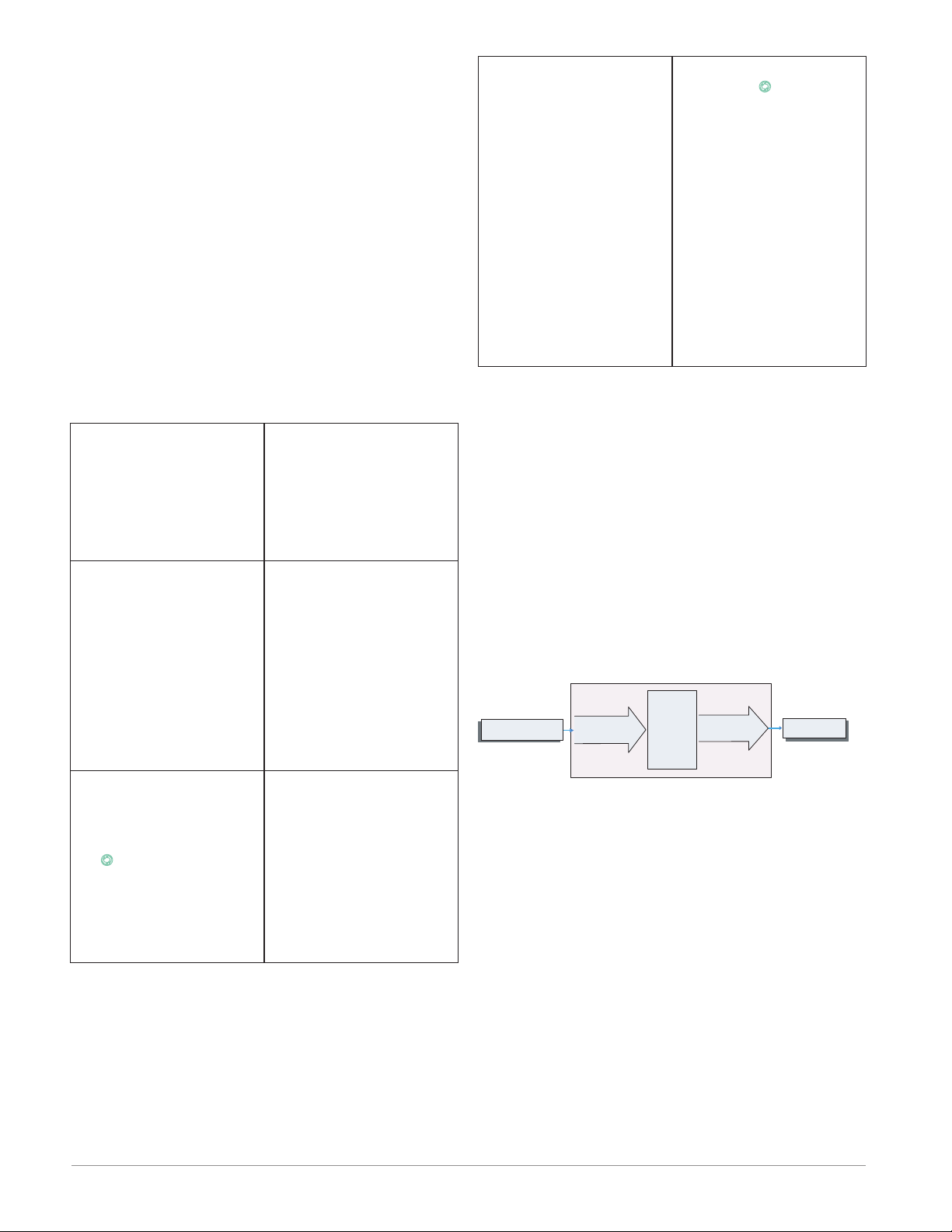
It is useful to think of the scanner in three parts:
inputs, procedures and outputs. Information flows
from an input to a procedure to an output when the
scanner is properly configured. An RMS module can
carry out several procedures at the same time, e.g.,
monitoring inputs for several different alarm situations, monitoring and acting upon digital inputs, and
outputs can be configured to drive devices such as
heaters, audible alarms, lights. Each process needs
to be thought out carefully and the scanner’s inputs,
procedures and outputs set up properly.
To set up a function, it’s important to tell it what
source, or instance, to use. For example, if the scanner is equipped with digital inputs they can be used
to silence an individual alarm or all alarms. The
RMS module can be equipped with up to 12 digital
inputs, instance 1 - 6 and 7 - 12.
Note:
Alarms will reset automatically when the condition
that caused the alarm goes back to a non-alarm
state if the alarm latching prompt is set to nonlatching (Setup Page, Alarm Menu).
Keep in mind that a function is a user-programmed
internal process that does not execute any action
outside of the controller. To have any affect outside
of the controller, an output must be configured to respond to a function.
Outputs
Outputs
Inputs
Prodedures
Process
Alarm
High
Silence
Alarms
Process
Alarm
Low
Tu rn Loop
Alarms off
Inputs
The inputs provide the information that any given
programmed procedure can act upon. Simply stated,
this information may come from an operator pushing
a button or from a sensor monitoring the temperature of a part being heated or cooled.
Each analog input typically uses a thermocouple,
RTD or thermistor to read the process temperature.
It can also read volts, current or resistance, allowing
it to use various devices to read humidity, air pressure, operator inputs and others values. Each analog
input must be configured to match the device connected to that input (see: Analog Input Menu, Setup
Page).
Each digital input reads whether a device is active
or inactive. An RMS module equipped with digital
input/output hardware includes two sets of terminals
where each of which can be used as either an input
or an output. Each pair of terminals must be configured to function as either an input or an output with
the direction parameter (see: Digital Input/Output
Menu, Setup Page).
Outputs can perform various functions or actions in
response to information provided by a function, such
as removal of the control voltage to a contactor; driving a heater; turning a light on or off; unlocking a
door; or turning on an audible alarm.
Assign an output to a function in the Output
Menu or Digital Input/Output Menu. Then select
which instance of that function will drive the selected output. For example, in using an RMS module, an
output can be configured to respond to the output of
the PID algorithm from another RM module to drive
a heat er.
You can assign more than one output to respond
to a single instance of a function. For example, alarm
2 could be used to trigger a light connected to output
1 and a siren connected to digital output 5.
Actions
Based on a given input (Digital I/O, Event output,
Logic function, etc..) the Action function can cause
other functions to occur. To name a few, set alarms to
off, silencing alarms and restoring user memory.
Functions
Functions use input signals to calculate a value. A
function may be as simple as reading a digital input
to set a state to true or false, or reading a temperature to set an alarm state to on or off.
Watlow EZ-ZONE® RMS Module • 5 • Chapter 1 Overview
Page 9

A Conceptual View of RM Hardware Configurations
Due to the scalability and flexibility in the RM system a user has several options available in the way
that the hardware can be connected. Listed below
are a few examples.
RMS Connected to a Remote User Interface (RUI)
and a Personal Computer (PC)
In this configuration the RUI and PC are connected
to the RMS module via Watlow's Standard Bus where
both will be able to talk directly to the RMS module.
RMS
Scanner
Slot C
Power
Supply
PC Running
EZ-ZONE
Configurator
RUI
In the graphic above the PC running EZ-ZONE Configurator software and or the RUI can be used to
configure and then monitor the RMS and other modules connected to it.
RMS Module Connected to a Programmable Logic
Controller (PLC) on a DIN Rail
steps below to switch the RMS to the Standard bus
protocol.
1. Disconnect all Modbus devices from the network
2. Push and hold the orange button on the face of
the module for approximately 6 seconds
3. When the LED display (above the orange button)
changes to P [p] momentarily release the orange
button and then push it again where [S] will appear (symbol for Standard Bus), release the orange button
4. Push the orange button again for approximately
3 seconds (LED display will become brighter) to
change the Standard Bus address if needed
RMS Module Connected to an Operator Interface
Terminal (OIT) through an RMA
In this configuration the RMS can be connected to
the OIT through the RMA running any of a number
of available protocols. The RMA and the OIT must
be using the same protocol while the communications
from RMA to the RMS module is accomplished over
the backplane using Watlow's Standard Bus protocol.
Available protocols in the RMA follow:
1. EtherNet/IP and or Modbus TCP
2. DeviceNet
3. Modbus RTU
4. Profibus DP
Slot E
RMS
Scanner
Slot C
RM
Access
Slot C
In this configuration the PLC can be connected to
the RMS module using the Modbus RTU protocol:
RMS
Scanner
Slot C
Power
Supply
PLC
In this example, the RMS module and the PLC must
be equipped with the Modbus RTU protocol.
Note:
If it is intended to use an RUI or a PC using EZZONE Configurator software it will be necessary to
switch the protocol on the RMS to Watlow's Standard Bus to successfully communicate; follow the
PC Running
EZ-ZONE
Configurator
RUI
OIT
Power
Supply
Notice that in the example above that there is an optional RUI connected to the RMS along with the OIT.
OITs' are not generally used to configure a control
but are used more for run-time information. As an alternative for configuration the RUI could be used to
configure and monitor in a remote location.
One advantage in using an RMA module when communicating on a network is that protocol switching
is not needed on the RMS module if using an RUI
or EZ-ZONE Configurator software. The protocol of
choice used with the RMA can run simultaneously
with the Standard Bus protocol.
RMS Connected to a Split Rail with OIT
In this configuration both the inter-module bus
(backplane communications) and Standard Bus are
Watlow EZ-ZONE® RMS Module • 6 • Chapter 1 Overview
Page 10
connected between rails to allow for remote capabilities. It is recommended that the split rail connection
not exceed 100 feet. In this configuration the OIT can
communicate with all modules (maximum 16 modules any combination with one Access module).
RM
Access
Slot C
Slot E
Power
Supply
RMC
Controller
RMC
Controller
Slot C
RMS
Scanner
RMS
Scanner
Slot C
Module Status (Slot A,
B, D, or E)
E
D
Protocol (Standard Bus red or Modbus - green)
Module outputs 1
through 16, all may or
A
B
may not be used depending on module type
Slot C
Slot C
OIT
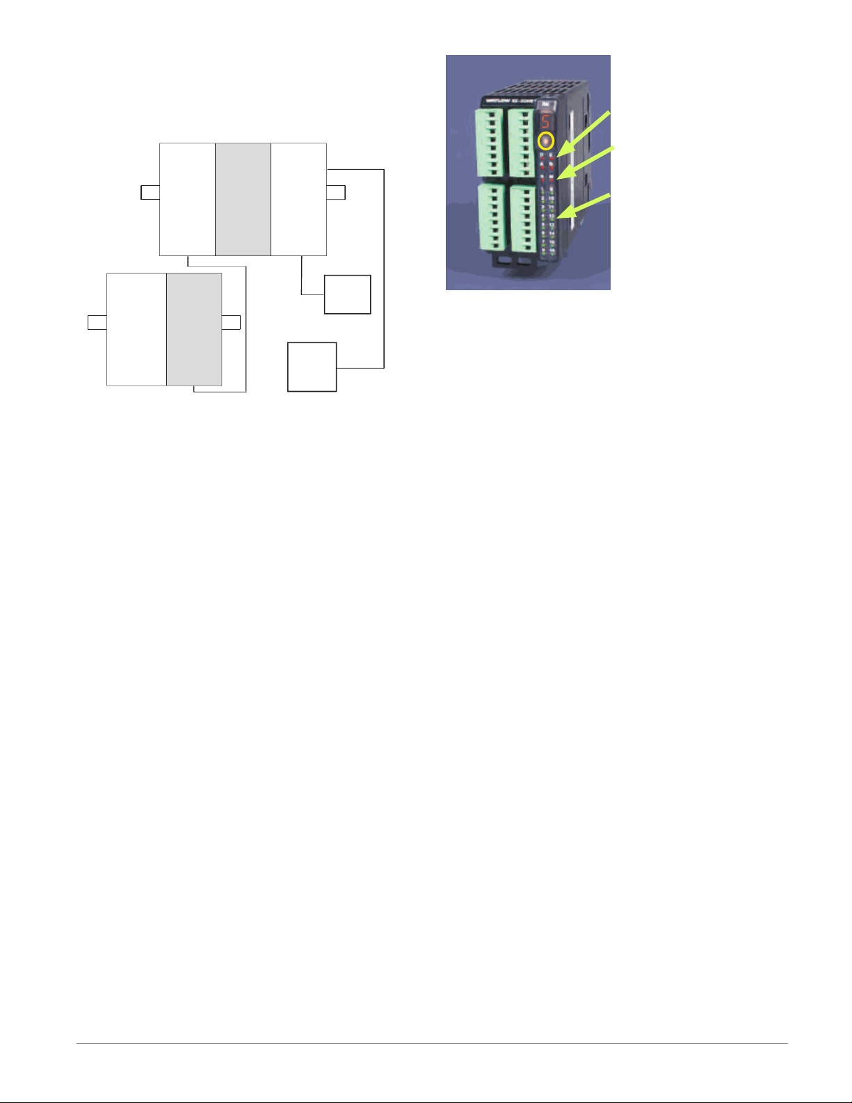
Module Orientation
The picture that follows represents one of several different RM modules. All of them will have four slots
on the face (slot A, B, D, and E) and one on the bottom (slot C) not shown. All of these slots are not always used on all modules. On the face of the module
there is a button (orange circle) under the zone address ([5]). When pushed and held it has the following
functions:
1. For any module, push and hold the orange button
for approximately 3 seconds to change the zone address. Valid addresses for Modbus and Standard
bus range from 1 -16 ([1] - [9], [a] is 10, [b] is 11, [C]
is 12, [d] is 13, [e] is 14, [f] is 15, and [h] is 16). The
RMA (Access) module is shipped at address [j] or
17 and is the only module that can have its address
set above 16.
2. When a module is equipped with the Modbus protocol (RMxxxxxxxxxx1xx) pushing and holding the
orange button for approximately 6 seconds will
cause the LED display to return [P] for protocol.
Releasing the button and then pushing it again
(within 6 seconds) the display will toggle between
[N] (Modbus) and [S] (Standard Bus).
Watlow EZ-ZONE® RMS Module • 7 • Chapter 1 Overview
Page 11
Getting Started Quickly
Consider taking the following steps to quickly commission your control:
• Wire and connect the power source to the control
• Wire and connect input and output devices to the
control
• Power up the control and navigate to the Setup
Page to configure inputs, outputs, adjust set
points, alarms, etc...
The RMS controller has a page and menu structure
that is listed below along with a brief description of
its purpose. The menu structure can be easily seen
and navigated using EZ-ZONE Configurator soft-
ware or the Remote User Interface (RUI).
Note:
The menu navigation as described below applies
when the RMS is connected to the RUI which is optional equipment.
Setup Page
Using the RUI, push
and hold the up and
down keys (¿ ¯) for 6
seconds to enter. (See
the Setup Page for further information)
Operations Page
Using the RUI push and
hold the up and down
keys (¿ ¯) for 3 seconds
to enter. (See the Op-
erations Page for further
information)
Factory Page
Using the RUI push and
hold the Infinity and
the green Advance keys
(ˆ ‰) for 6 seconds to
enter. (See the Factory
Page for further infor-
mation)
A user would want to
setup their control prior
to operation. As an example, define the input
type, alarm sides (high
and or low) or set the
output function.
After setting up the
control to reflect your
equipment, the Operations Page would
be used to monitor or
change runtime settings.
As an example, the user
may want to see the current status (on or off) of
an event in the Action
Menu.
For the most part the
Factory Page has no
bearing on the control when running. A
user may want to enable password protection, view the control
part number or perhaps
create a custom Home
Page.
Home Page
When using the RUI,
the control is at the
Home Page when ini-
tially powered up where
it will display the value
of Analog Input 1 in the
upper display and the
value of Analog Input 2
in the lower display.
Pushing the green Advance Key ‰ will cause
the display to show the
value of Analog Input 1
in the upper display and
Analog Input 2 in the
lower display. With each
successive push of the
green advance key the
display will sequentially
show the value of all
Note:
The Home Page is visible only when using
the RUI.
remaining analog inputs
in the upper display and
the lower display will
show the corresponding LED display. (e.g.,
[AIN3] for input 3)
The default RMS loop configuration out of the box is
shown below:
• All Analog Input functions are set to thermocouple, type J (to change go to the Setup Page, Analog Input Menu)
• All Process Value functions are set to off (to
change go to the Setup Page, Process Value
Menu)
• All outputs are set to off (to change go to the Setup Page, Output Menu)
Once the scanner has been wired and setup, power
up the control. If using an RUI the upper display will
show the value of Analog Input 1 and the lower display will show the value of Analog Input 2.
EZ-ZONE RMS Default Configuration
Input
Function
Input Sensor
All Analog Inputs
Thermocouple Type J
Alarm
Types
Off
All Outputs
Output
Function
Off
Watlow EZ-ZONE® RMS Module • 8 • Chapter 1 Overview
Page 12
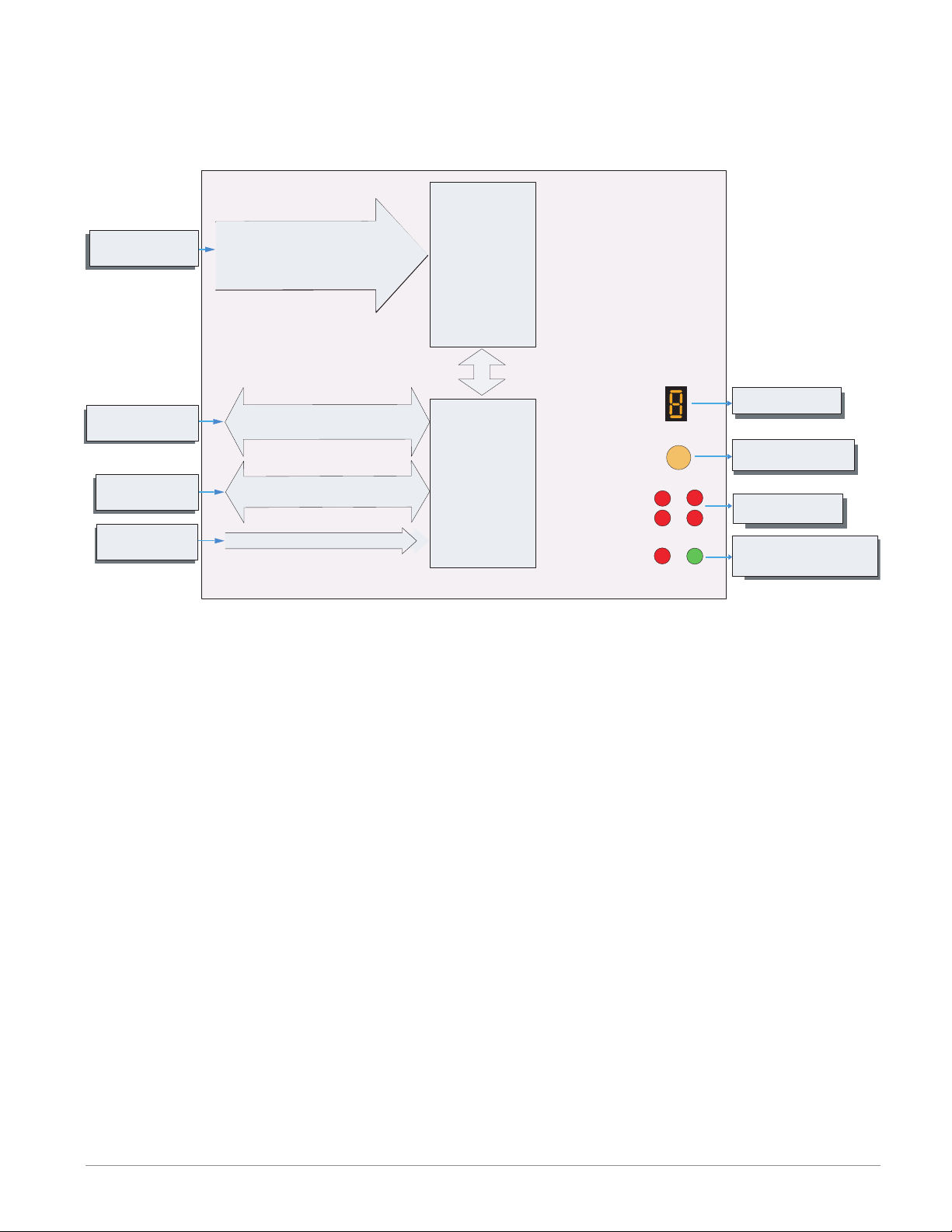
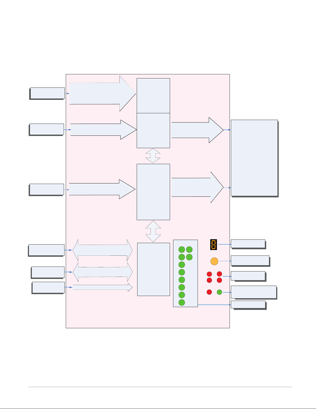
EZ-ZONE RMS Module - System Diagram
16 Scanner Channels - Slots A, B, D and E
R M S x - [R,P] [R,P] [R,P] [R,P] - A A A A
Input
Function
Input Sensor
RUI,
PC, PLC or HMI
Other RM Modules
Power Supply
Analog Input 1 through 16
None, Thermocouple, 2-Wire RTD (100, 1k),
Thermistor (5k, 10K, 20k, 40k), Process
(V, mV, mA) or 1K Potentiometer
EIA - 485 Communications
Standard Bus
(optional Modbus RTU)
Inter-module Bus
20.4 to 30.8 Vac or Vdc
Alarms
Slot A, B, D, E
Modbus RTU
Address 1 - 16
Standard Bus
Zone 1 - 16
Supervisory &
Power Board
Slot C
Zone and Status
LED
Zone Selection
Button
D
A
S
Function
Indicates Zone
Push to select Zone
Address and Protocol
E
B
M
Card Status
Slots A, B, D, E
Indicates communications
activity (Modbus or Standard Bus)
Output
Address
Watlow EZ-ZONE® RMS Module • 9 • Chapter 1 Overview
Page 13
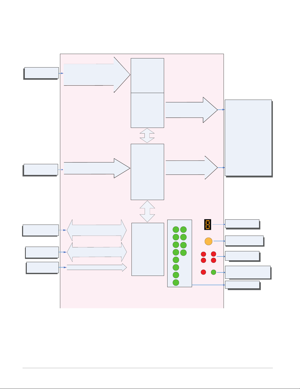
EZ-ZONE RMS Module - System Diagram
Output
Input
8 Scanner Channels - Slots A, B
4 - Form A Mechanical Relays - Slot D
6 - Digital I/O - Slot E
R M S x - [R,P] [R,P] J C - A A A A
Function
Input Sensor
Input Device
Analog Input 1 through 8
None, Thermocouple, 2-Wire RTD (100, 1k),
Thermistor (5k, 10K, 20k, 40k), Process
(V, mV, mA) or 1K Potentiometer
Digital Input 7, 8, 9, 10, 11 or 12
Switch contact or volts dc
Alarms
Slot A, B
4 - Mechanical
Relay Outputs
Form A
Slot D
6 - Digital
Inputs / Outputs
any combination
Slot E
Output 1, 2, 3, 4
5A Mechanical Relay Form A
Output 7, 8, 9, 10, 11 or 12
switched dc/open collector
Function
Analog Input
Alarm
Cool Power
Heat Power
Compare
Counter
Digital I/O
Profile Event Output A-H
Function Key
Linearization
Logic
Math
Process Value
Special Output Function 1-4
Timer
Variable
Off
RUI,
PC, PLC or HMI
Other RM Modules
Power Supply
EIA - 485 Communications
Standard Bus
(optional Modbus RTU)
Inter-module Bus
20.4 to 30.8 Vac oe Vdc
Some input/output combinations not possible, see ordering matrix
Zone and Status
Output Status
Modbus RTU
Address 1 - 16
Standard Bus
Zone 1 - 16
Supervisory &
Power Board
Slot C
LEDs
1
2
3
4
5
6
7
8
9
10
11
12
LED
Zone Selection
Button
D
A
S
Indicates Zone
Push to select Zone
Address and Protocol
E
B
M
Card Status
Slots A, B, D, E
Indicates communications
activity (Modbus or Standard Bus)
Indicates I/O
Address
Status
Watlow EZ-ZONE® RMS Module • 10 • Chapter 1 Overview
Page 14
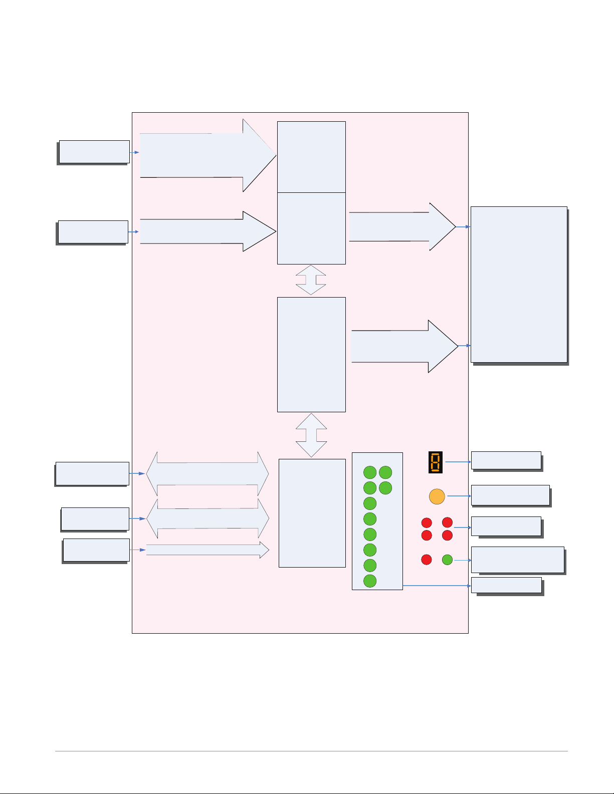
EZ-ZONE RMS Module - System Diagram
Output
Input
8 Scanner Channels - Slots A, B
6 - Digital I/O - Slot D
4 - Form A Mechanical Relays - Slot E
R M S x - [1,2] [1,2] C J - A A A A
Function
Input Sensor
Input Device
Analog Input 1 through 8
None, Thermocouple, 2-Wire RTD (100, 1k),
Thermistor (5k, 10K, 20k, 40k), Process
(V, mV, mA) or 1K Potentiometer
Digital Input 1, 2, 3, 4, 5 or 6
Switch contact or volts dc
Alarms
Slot A, B
6 - Digital
Inputs / Outputs
any combination
Slot D
4 - Mechanical
Relay Outputs
Form A
Slot E
Output 1, 2, 3, 4, 5 or 6
switched dc/open collector
Output 7, 8, 9, 10
5A Mechanical Relay Form A
Function
Analog Input
Alarm
Cool Power
Heat Power
Compare
Counter
Digital I/O
Profile Event Output A-H
Function Key
Linearization
Logic
Math
Process Value
Special Output Function 1-4
Timer
Variable
Off
RUI,
PC, PLC or HMI
Other RM Modules
Power Supply
EIA - 485 Communications
Standard Bus
(optional Modbus RTU)
Inter-module Bus
20.4 to 30.8 Vac oe Vdc
Some input/output combinations not possible, see ordering matrix
Zone and Status
Output Status
Modbus RTU
Address 1 - 16
Standard Bus
Zone 1 - 16
Supervisory &
Power Board
Slot C
LEDs
1
2
3
4
5
6
7
8
9
10
LED
Zone Selection
Button
D
A
S
Indicates Zone
Push to select Zone
Address and Protocol
E
B
M
Card Status
Slots A, B, D, E
Indicates communications
activity (Modbus or Standard Bus)
Indicates I/O
Address
Status
Watlow EZ-ZONE® RMS Module • 11 • Chapter 1 Overview
Page 15
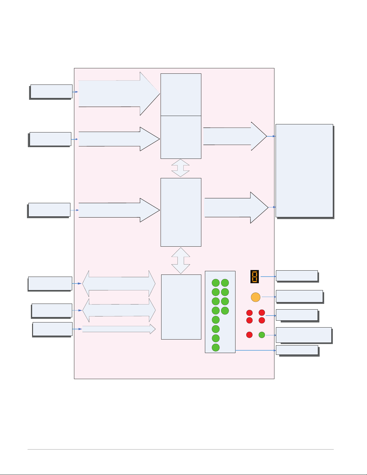
EZ-ZONE RMS Module - System Diagram
Output
Input
8 Scanner Channels - Slots A, B
6 - Digital I/O - Slot D
6 - Digital I/O - Slot E
R M S x - [1,2] [1,2] C C - A A A A
Function
Input Sensor
Input Device
Input Device
Analog Input 1 through 8
None, Thermocouple, 2-Wire RTD (100, 1k),
Thermistor (5k, 10K, 20k, 40k), Process
(V, mV, mA) or 1K Potentiometer
Digital Input 1, 2, 3, 4, 5, 6
Switch contact or volts dc
Digital Input 7, 8, 9, 10, 11, 12
Switch contact or volts dc
Alarms
Slot A, B
6 - Digital
Inputs / Outputs
any combination
Slot D
6 - Digital
Inputs / Outputs
any combination
Slot E
Output 1, 2, 3, 4, 5, 6
switched dc/open collector
Output 7, 8, 9, 10, 11, 12
switched dc/open collector
Function
Analog Input
Alarm
Cool Power
Heat Power
Compare
Counter
Digital I/O
Profile Event Output A-H
Function Key
Linearization
Logic
Math
Process Value
Special Output Function 1-4
Timer
Variable
Off
RUI,
PC, PLC or HMI
Other RM Modules
Power Supply
EIA - 485 Communications
Standard Bus
(optional Modbus RTU)
Inter-module Bus
20.4 to 30.8 Vac oe Vdc
Some input/output combinations not possible, see ordering matrix
Zone and Status
Output Status
Modbus RTU
Address 1 - 16
Standard Bus
Zone 1 - 16
Supervisory &
Power Board
Slot C
LEDs
1
2
3
4
5
6
7
8
9
10
11
12
LED
Zone Selection
Button
D
A
S
Indicates Zone
Push to select Zone
Address and Protocol
E
B
M
Card Status
Slots A, B, D, E
Indicates communications
activity (Modbus or Standard Bus)
Indicates I/O
Address
Status
Watlow EZ-ZONE® RMS Module • 12 • Chapter 1 Overview
Page 16
EZ-ZONE RMS Module - System Diagram
8 Scanner Channels - Slots A, B
6 - Digital I/O - Slot D
1 - Digital Input/2 Mechanical Relays - Slot E
R M S x - [1,2] [1,2] C B - A A A A
Input
Function
Input Sensor
Input Device
Input Device
Analog Input 1 through 8
None, Thermocouple, 2-Wire RTD (100, 1k),
Thermistor (5k, 10K, 20k, 40k), Process
(V, mV, mA) or 1K Potentiometer
Digital Input 1, 2, 3, 4, 5 or 6
Switch contact or volts dc
Digital Input 9
Switch contact or volts dc
Alarms
Slot A, B
6 - Digital
Inputs / Outputs
any combination
Slot D
1 - Digital Input
2 - Mechanical
Relay Outputs
Slot E
Output 1, 2, 3, 4, 5 or 6
switched dc/open collector
Output 7
5A Mechanical Relay Form C
Output 8
5A Mechanical Relay Form A
Output
Function
Analog Input
Alarm
Cool Power
Heat Power
Compare
Counter
Digital I/O
Profile Event Output A-H
Function Key
Linearization
Logic
Math
Process Value
Special Output Function 1-4
Timer
Variable
Off
RUI, EZ-ZONE PM/ST,
PC, PLC or HMI
Other RM Modules
Power Supply
EIA - 485 Communications
Standard Bus
(optional Modbus RTU)
Inter-module Bus
20.4 to 30.8 Vac oe Vdc
Some input/output combinations not possible, see ordering matrix
Zone and Status
Output Status
Modbus RTU
Address 1 - 16
Standard Bus
Zone 1 - 16
Supervisory &
Power Board
Slot C
LEDs
1
2
3
4
5
6
7
8
9
10
LED
Zone Selection
Button
D
A
S
Indicates Zone
Push to select Zone
Address and Protocol
E
B
M
Card Status
Slots A, B, D, E
Indicates communications
activity (Modbus or Standard Bus)
Indicates I/O
Address
Status
Watlow EZ-ZONE® RMS Module • 13 • Chapter 1 Overview
Page 17
2
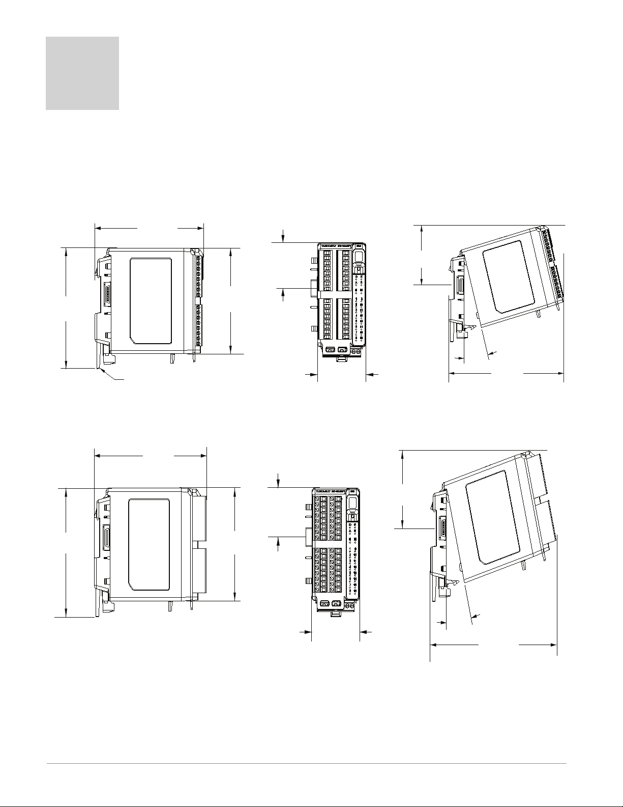
147.07 mm
( 5.8 in )
116.08 mm
( 4.57 in )
101.60 mm
( 4.00 in )
44.45 mm
( 1.75 in )
51.56 mm
( 2.03 in )
75.08 mm
( 3.0 in )
15
165 mm
( 6.50 in )
Module Removal Displacement
Latch in open position
155 mm
( 6.10 in )
116.08 mm
( 4.57 in )
101.60 mm
( 4.00 in )
44.45 mm
( 1.75 in )
51.56 mm
( 2.03 in )
75.08 mm
( 3.0 in )
15
°
173.90 mm
( 6.85 in )
Module Removal Displacement
Chapter 2: Install and Wire
Dimensions
As can be seen below the dimensions of the RM system will change slightly based on the type of connector
used.
Module Removal Clearance Standard Connectors
Module Removal Clearance Straight Connectors
Watlow EZ-ZONE® RMS Module • 14 • Chapter 2 Install and Wire
Page 18
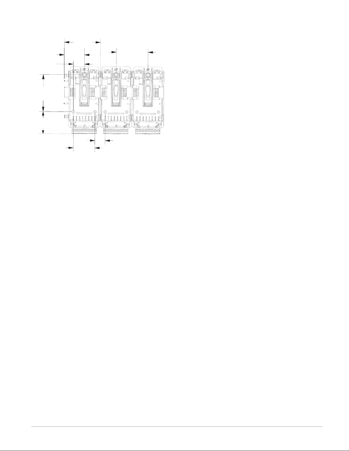
Chassis Mount Front View (Module Removed) - Screw Connection Pattern
58.67 mm
(2.31 in)
51.56 mm
(2.03 in)
16.76 mm
(.66 in)
17.53 mm
(.69 in)
60.45 mm
(2.38 in)
35.81 mm
(1.41 in)
32.77 mm
(1.29 in)
35.05 mm
(1.38 in)
The view above is representative of the modular backplane without the module.
Recommended chassis mount hardware:
1. #8 screw, 3/4" long
2. Torque to 10 -15 lb-in
3. No washers of any kind
Watlow EZ-ZONE® RMS Module • 15 • Chapter 2 Install and Wire
Page 19
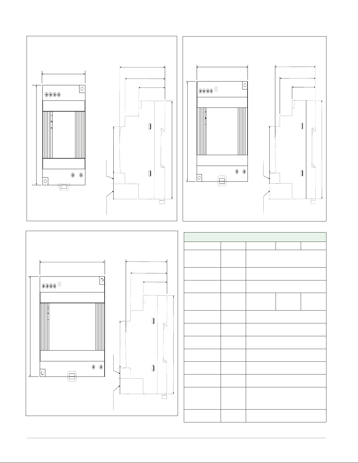
Power Supplies
DSP30
+ +
-
-
L N
DC LO
DC OK
123 4
5 6
53.00 mm
DSP30
2.087 in
91.00 mm
3.583 in
14.20 mm
9.75 mm
43.1 mm
91.00 mm
55.6 mm
49.00 mm
32.10 mm
0.559 in
1.697 in
0.384 in
3.583 in
2.189 in
1.929 in
1.264 in
DSP60
vout ADJ.
+ +
-
-
L N
DC LO
DC OK
123 4
5 6
DSP60
71.00 mm
2.795 in
91.00 mm
3.583 in
14.20 mm
9.75 mm
43.1 mm
91.00 mm
55.6 mm
49.00 mm
32.10 mm
0.559 in
1.697 in
0.384 in
3.583 in
2.189 in
1.929 in
1.264 in
DSP100
DC LO
DC OK
vout ADJ.
+ +
-
-
L N
123 4
5 6
DSP100
89.9 mm
3.539 in
91.00 mm
3.583 in
5
14.20 mm
9.75 mm
43.1 mm
91.00 mm
56.8 mm
49.00 mm
32.10 mm
0.559 in
1.697 in
0.384 in
3.583 in
2.236 in
1.929 in
1.264 in
Power Supply Specifications
DSP 30 DSP 60 DSP 100
AC Input Volt-
age Range
Input Fre-
quency
DC Input Volt-
age range
VAC
Hz 47 - 63Hz
VDC 120 - 370VDC
Inrush Cur-
rent (115 /
A 25 / 50A 30 / 60A 30 / 60A
230VAC)
Output Volt-
age Accuracy
Over voltage
Protection
LED Indica-
tors
Operating
Temperature
Storage Tem-
perature
Operating Hu-
midity
Vibration (Op-
erating)
% ±1% of Nominal
V 120 - 145%
- - - -
- - - -
- - - - -25 to +85°C
- - - - 20 - 95% RH (non condensing)
- - - -
Safety Agency
Approvals
For a comprehensive listing of these specifications point your
browser to : http://us.tdk-lambda.com/lp/products/dsp-series.htm
90 - 264VAC, Class II double in-
sulated (No ground connection
required)
Green LED = On, Red LED = DC
Output Low
-25 to +71°C (Derate linearly
2.5%/°C from 55 to 71°C)
IEC 60068-2-6 (Mounting by rail:
Random wave, 10-500 Hz, 2G, ea.
along X, Y, Z axes 10 min/cycle,
60 min)
UL1310 Class 2(1), UL508 Listed,
UL60950-1, EN60950-1, CE
Watlow EZ-ZONE® RMS Module • 16 • Chapter 2 Install and Wire
Page 20
RMS Installation and Removal on a DIN Rail
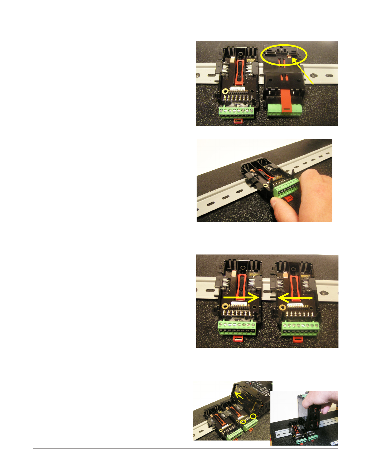
Modular Backplane Connector
The picture on the right shows the Modular Backplane
Connector, both front and rear view. The rear view
is bringing in to focus a metal clip. If the DIN rail is
grounded the Modular Backplane Connector and the
module connected to it will be also (recommended).
Installing the Modular Backplane Connector
Step 1
Hook backplane assembly to upper edge of DIN rail,
(see rear view above, backplane hook detail that
mates with upper rail edge is circled)
Step 2
Next, rotate back plane assembly downward to en
gage the lower edge of the rail. (Note: Din Rail clip ping distance ranges from 1.366 -1.389 inches. The
back plane assembly will not latch onto the rail suc cessfully if the rail is out of dimension).
Step 3
For final positioning and locking, the red tab is to
be pushed upward to further engage the bottom
edge of the rail with an over center snap action
latch. (The red locking tab protrudes from the bot tom side of the back plane assembly).
Installing Multiple Modular Backplane Connectors
Multiple modules are easily aligned and latched together. Each module includes matched mating geometry that facilitates accurate and consistent interconnections. The recommended method of multi-module
attachment is to first attach individual modules to
the rail separately and second to laterally slide the
modules together until they touch. (Refer to steps 1&2
above). When the multi-module system is attached and
laterally positioned to the desired placement the locking tab should be engaged to secure the control system
to the rail, (Refer to step 3 above).
Module Installation
In the picture to the right notice that the arrow is
pointing at the top lip of the module (on side). When installing the module simply slide this lip over the top of
the Modular Backplane Connector and then push down
on the rear of the module where it will seat on the two
posts just above the green connector.
Watlow EZ-ZONE® RMS Module • 17 • Chapter 2 Install and Wire
Page 21
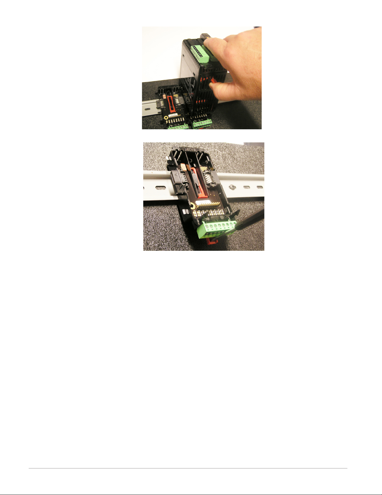
Module Removal
To remove a module from the
Modular Backplane Connector
find the red tab protruding from
the bottom of the module and pull
back on it as shown to the right.
While pulling back on the red tab
the two mounting posts will release the module where the module can then be lifted up and out
of the Modular Backplane Connector.
Removal of the Modular Backplane Connector
A module can be removed from
the Modular Backplane Connector
by inserting a screw driver into
the red locking tab just behind
the green connector and applying
downward pressure on the tab by
lifting the screwdriver upwards.
When released, the tab will move
downward and the connector can
then be lifted up off of the DIN
rail.
Watlow EZ-ZONE® RMS Module • 18 • Chapter 2 Install and Wire
Page 22
Wiring
Scanner Module (R M S x - x x x x - x x x x)
Slot A Slot B Slot D Slot E Configuration
Universal, RTD and Thermistor Inputs 1 -16
1 - 4 5 - 8 9 - 12 13 - 16
S1
R1
S2
R2
S3
R3
S4
R4
- - -
- - -
- - -
- - -
- - -
- - -
- - -
- - -
- - - - - - - - - 9
- - -
- - -
- - -
- - -
- - -
- - -
- - -
- - -
S5
R5
S6
R6
S7
R7
S8
R8
- - -
- - -
- - -
- - -
- - -
- - -
- - -
- - -
- - -
- - -
- - -
- - -
- - -
- - -
- - -
- - -
S9
R9
S10
R10
S11
R11
S12
R12
1 - 6 7-12
B1
D1
D2
D3
D4
D5
D6
Z1
- - -
- - -
- - -
- - -
- - -
- - -
- - -
- - -
S13
R13
S14
R14
S15
R15
S16
R16
B7
D7
D8
D9
D10
D11
D12
Z7
- - -
- - -
- - -
- - -
- - -
- - B9
D9
S_ (RTD), thermocouple -, volts - , mA -, potentiometer wiper or thermistor
R_ (RTD), thermocouple +, volts +, mA +, potentiometer or thermistor
Digital Inputs 1 - 6 and 7 - 12
Common
DC +input
DC +input
DC +input
DC +input
DC +input
DC +input
Internal Supply
Digital Input 9
Common
DC +input
Universal/Thermistor Input
Part # Digits 5, 6, 7, 8
Input 1-4: RMSx-[R,P]xxx-xxxx
Input 5-8: RMSx-x[R,P]xx-xxxx
Input 9-12: RMSx-xx[R,P]x-xxxx
Input 13-16: RMSx-xxx[R,P]-xxxx
Digital Inputs (DI)
Part # Digit 7, 8
Slot A: Option not valid
Slot B: Option not valid
Slot D: RMSx-xx[C]x-xxxx
Slot E: RMSx-xxx[C]-xxxx
Digital Input (DI)
Part # Digit 8
Slot A: Option not valid
Slot B: Option not valid
Slot D: Option not valid
Slot E: RMSx-xxx[B]-xxxx
- - - - - - - 1 - 4 7 - 10
- - -
- - -
- - -
- - -
- - -
- - -
- - -
- - -
- - - - - - 1 - 6 7 - 12
- - -
- - -
- - -
- - -
- - -
- - -
- - -
- - -
- - -
- - -
- - -
- - -
- - -
- - -
- - -
- - -
- - -
- - -
- - -
- - -
- - -
- - -
- - -
- - -
L1
K1
L2
K2
L3
K3
L4
K4
B1
D1
D2
D3
D4
D5
D6
Z1
L7
K7
L8
K8
L9
K9
L10
K10
B7
D7
D8
D9
D10
D11
D12
Z7
Form A - Mechanical Relay Outputs 1- 4 and 7 - 10
normally open
common
normally open
common
normally open
common
normally open
common
Digital Outputs 1 - 6 and 7 - 12
Common
open collector/ switched dc
open collector/ switched dc
open collector/ switched dc
open collector/ switched dc
open collector/ switched dc
open collector/ switched dc
Internal Supply
Mechanical Relay 5 A, Form A
Part # Digits 7, 8
Slot D: : RMSx-xx[J]x-xxxx
Slot E: : RMSx-xxx[J]-xxxx
Digital Outputs (DO)
Part # Digit 7, 8
Slot A: Option not valid
Slot B: Option not valid
Slot D: RMSx-xx[C]x-xxxx
Slot E: RMSx-xxx[C]-xxxx
Watlow EZ-ZONE® RMS Module • 19 • Chapter 2 Install and Wire
Page 23

Form C - Mechanical Relay Output 7 and Form A - Mechanical Relay Output 8
Slot A Slot B Slot D Slot E Configuration
- - - - - - - - - - 7 and 8
- - -
- - -
- - -
- - -
- - -
- - -
- - -
- - -
- - -
- - -
- - -
- - -
- - -
- - -
- - -
- - -
Slot C Configuration
98
99
CF
CD
CE
CC
CA
CB
CZ
CX
CY
- - -
- - -
- - -
- - -
- - -
- - -
- - -
- - -
Power input: ac or dc+
Power input: ac or dc-
Standard Bus EIA-485 common
Standard Bus EIA-485 T-/RStandard Bus EIA-485 T+/R+
Standard Bus or Modbus RTU EIA-485 common
Standard Bus or Modbus RTU EIA-485 T-/RStandard Bus or Modbus RTU EIA-485 T+/R+
Inter-module Bus
Inter-module Bus
Inter-module Bus
L7
K7
J7
L8
K8
- - -
- - -
- - -
normally open
common
normally closed
normally open
common
Power and Communications
Form C and Form A Relay Outputs
Part # Digit 8
Slot A: Option not valid
Slot B: Option not valid
Slot D: Option not valid
Slot E: RMSx-xxx[B]-xxxx
All
Standard Bus
Part # Digit 10
RMSx-xxxx-x[A]xx
Standard Bus or Modbus
Part # Digit 10
RMSx-xxxx-x[1]xx
Inter-module Bus
Watlow EZ-ZONE® RMS Module • 20 • Chapter 2 Install and Wire
Page 24
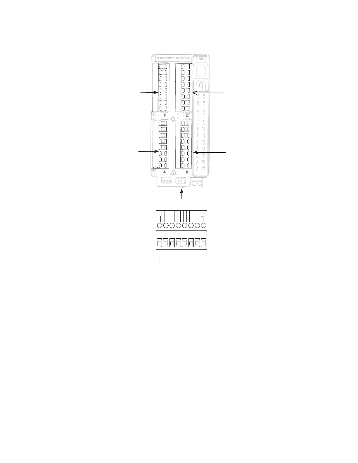
RMS Module - Front View -
S
l
o
t
C
Standard Connector
Slot D
Slot A
98
Slot E
Slot B
Slot C
99
power
Watlow EZ-ZONE® RMS Module • 21 • Chapter 2 Install and Wire
Page 25

RMS System Isolation Blocks
Controller Power Supply
20.4 to 30.8VÎ (dc)
20.4 to 30.8VÅ (ac)
Safety Isolation
Mechanical Relay,
Outputs
Safety Isolation
Safety Isolation
Controller
Low Voltage Power Bus
Low-voltage Isolation: 42V peak
Safety Isolation: 1,528VÅ (ac)
No Isolation
Low-voltage
Isolation
Low-voltage
Isolation
Digital Inputs & Outputs
Analog Input 1 - 16
Communications Ports
Watlow EZ-ZONE® RMS Module • 22 • Chapter 2 Install and Wire
Page 26
Warning: ç
Slot A, B, D, E
Use National Electric (NEC) or other
country-specific standard wiring and
safety practices when wiring and
connecting this controller to a power
source and to electrical sensors or peripheral devices. Failure to do so may
result in damage to equipment and
property, and/or injury or loss of life.
Note:
Maximum wire size termination and
torque rating:
• 0.0507 to 3.30 mm2 (30 to 12 AWG)
single-wire termination or two 1.31
mm2 (16 AWG)
• 0.8 Nm (7.0 in-lb.) torque
Note:
Adjacent terminals may be labeled
differently, depending on the model
number.
Note:
To prevent damage to the controller,
do not connect wires to unused terminals.
Note:
Maintain electrical isolation between
digital input-outputs, switched dc/open
collector outputs and process outputs
to prevent ground loops.
Scanner Module Wiring (RMSx-xxxx-xxxx)
Low Power
RMS- ALL Model Numbers
• 20.4 to 30.8 V Å (ac) / Î (dc)
• 47 to 63 Hz
• 14VA (ac), 7 VA (dc) maximum consumption
• Controller module power consumption, 7 Watts maximum
• 31 Watts maximum power available for P/S part
#:0847-0299-0000
• 60 Watts maximum power available for P/S part
#:0847-0300-0000
• 91 Watts maximum power available for P/S part
#:0847-0301-0000
• Class 2 or SELV power source required to meet UL
compliance standards
98
99
power
t
C
l
o
S
Communications
RMS Part # Digit 10 is A
t
C
l
o
S
• CF, CD, CE - Standard Bus EIA485 Communications
• CZ, CX, CY - Inter-module Bus EIA485 Communica-
tions
• Do not route network wires with power wires. Connect
CF
CD
Standard Bus
Common
T- / R-
CE
T+ / R+
CZ
CX
Inter-module Bus
Common
-
CY
+
network wires in daisy-chain fashion when connecting
multiple devices in a network
Warning: ç
Explosion Hazard – Substitution of
component may impair suitability for
CLASS I, DIVISION 2.
Warning: ç
Explosion Hazard - Do not disconnect
while the circuit is live or unless the
area is known to be free of ignitable
concentrations of flammable substances.
Communications
RMS Part # Digit 10 is 1
t
C
l
o
S
• CC, CA, CB - Modbus and Standard Bus EIA-485
Communications (selectable via push button under
zone address)
CC
Common
CA
T- / R-
Modbus
CB
T+ / R+
CX
CZ
Common
Inter-module Bus
-
CY
+
• CZ, CX, CY - Inter-module Bus EIA-485 Communications
• Do not route network wires with power wires. Connect network wires in daisy-chain fashion when connecting multiple devices in a network
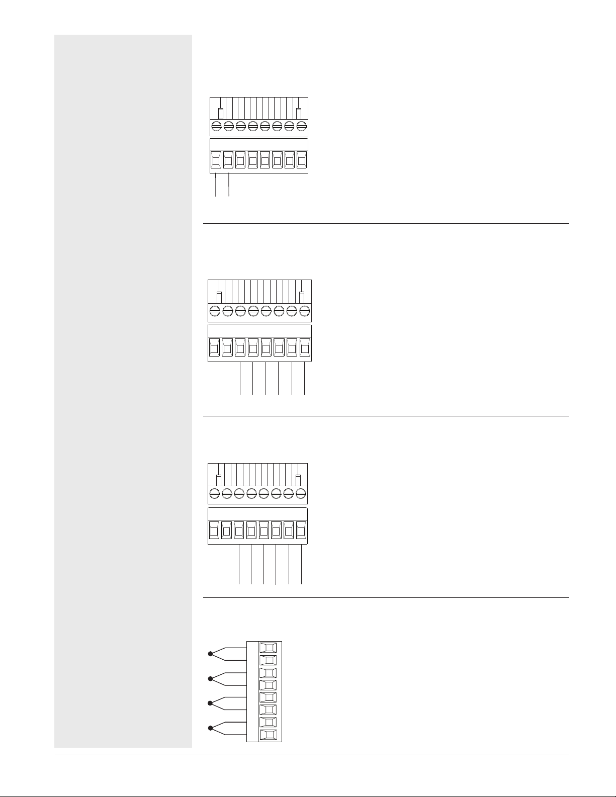
Inputs 1 through 16 Thermocouple
RMS Part # Digits 5, 6, 7, 8
-
S_
+
R_
-
S_
+
R_
-
S_
+
R_
-
S_
+
R_
• 2K Ω maximum source resistance
• >20 MΩ input impedance
• 3 microampere open-sensor detection
• Thermocouples are polarity sensitive. The negative
lead (usually red) must be connected to S terminal
• To reduce errors, the extension wire for thermocouples
must be of the same alloy as the thermocouple.
Input 1 - 4 (top to bottom): RMSx-(R)xxx-xxxx
Input 5 - 8 (top to bottom): RMSx-x(R)xx-xxxx
Input 9 - 12 (top to bottom): RMSx-xx(R)x-xxxx
Input 13 - 16 (top to bottom): RMSx-xxx(R)-xxxx
Watlow EZ-ZONE® RMS Module • 23 • Chapter 2 Install and Wire
Page 27
Warning: ç
Slot A, B, D, E
Slot A, B, D, E
Slot A, B, D, E
RTD
Slot A, B, D, E
Use National Electric (NEC) or other
country-specific standard wiring and
safety practices when wiring and
connecting this controller to a power
source and to electrical sensors or peripheral devices. Failure to do so may
result in damage to equipment and
property, and/or injury or loss of life.
Note:
Maximum wire size termination and
torque rating:
• 0.0507 to 3.30 mm2 (30 to 12 AWG)
single-wire termination or two 1.31
mm2 (16 AWG)
• 0.8 Nm (7.0 in-lb.) torque
Note:
Adjacent terminals may be labeled
differently, depending on the model
number.
Note:
To prevent damage to the controller,
do not connect wires to unused terminals.
Note:
Maintain electrical isolation between
digital input-outputs, switched dc/open
collector outputs and process outputs
to prevent ground loops.
Warning: ç
Explosion Hazard – Substitution of
component may impair suitability for
CLASS I, DIVISION 2.
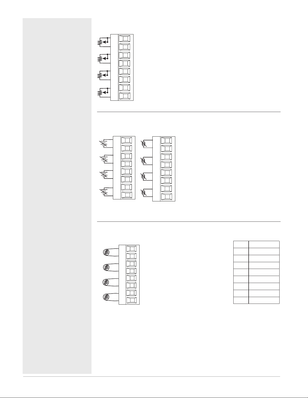
Inputs 1 through 16 Potentiometer
RMS Part # Digits 5, 6, 7, 8
CW
S_
R_
CCW
CW
CCW
CW
CCW
CW
CCW
S_
R_
S_
R_
S_
R_
• Use a 1 kΩ potentiometer.
Input 1 - 4 (top to bottom): RMSx-(R)xxx-xxxx
Input 5 - 8 (top to bottom): RMSx-x(R)xx-xxxx
Input 9 - 12 (top to bottom): RMSx-xx(R)x-xxxx
Input 13 - 16 (top to bottom): RMSx-xxx(R)-xxxx
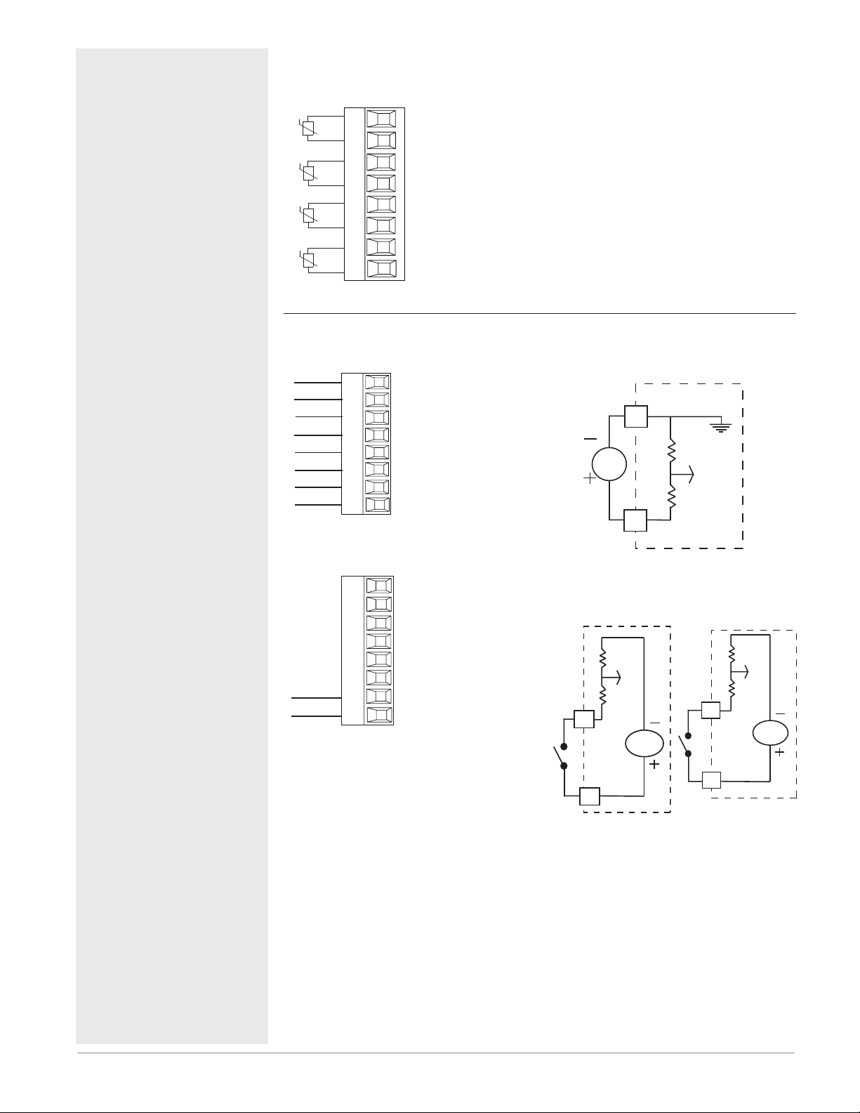
Inputs 1 through 16 Process
RMS Part # Digits 5, 6, 7, 8
-
S_
+
R_
-
S_
+
R_
-
S_
+
R_
-
S_
+
R_
volts
-
+
-
+
-
+
-
+
S_
R_
S_
R_
S_
R_
S_
R_
amperes
• 0 to 20 mA @ 100 Ω input impedance
• 0 to 10VÎ (dc) @ 20 kΩ input impedance
• 0 to 50 mVÎ (dc) @ 20 MΩ input impedance
• scalable
Input 1: RMS(1,3,5)xxxxxxxxxxx
(S1-/R1+),(T1+/S1-)
Input 2: RMSxx(1,5)xxxxxxxxx
(S2-/R2+),(T2+/S2-)
Input 3: RMSxxxx(1,5)xxxxxxx
(S3-/R3+),(T3-S3-R3)
Input 4: RMSxxxxxx(1,5)xxxxx
(S4-/R4+),(T4+/S4-)
Warning: ç
Explosion Hazard - Do not disconnect
while the circuit is live or unless the
area is known to be free of ignitable
concentrations of flammable substances.
Inputs 1 through 16 RTD
RMS Part # Digits 5, 6, 7, 8
• platinum, 100 and 1,000 Ω @ 0°C
S_
R_
S_
R_
S_
R_
S_
R_
2-wire
• calibration to DIN curve (0.00385
Ω/Ω/°C)
• RTD excitation current of 0.09
mA typical. Each ohm of lead
resistance may affect the reading
by 2.55°C for a 100 ohm platinum
sensor or 2.5 ohms for a 1000
ohm sensor.
Input 1 - 4 (top to bottom): RMSx-
(R)xxx-xxxx
Input 5 - 8 (top to bottom): RMSx-
x(R)xx-xxxx
Input 9 - 12 (top to bottom): RM-
Sx-xx(R)x-xxxx
Input 13 - 14 (top to bottom):
RMSx-xxx(R)-xxxx
AWG Ohms/1000ft
14 2.575
16 4.094
18 6.510
20 10.35
22 16.46
24 26.17
26 41.62
28 66.17
Watlow EZ-ZONE® RMS Module • 24 • Chapter 2 Install and Wire
Page 28
Warning: ç
Slot A, B, D, E
Slot D, E
Int
Slot E
Use National Electric (NEC) or other
country-specific standard wiring and
safety practices when wiring and
connecting this controller to a power
source and to electrical sensors or peripheral devices. Failure to do so may
result in damage to equipment and
property, and/or injury or loss of life.
Note:
Maximum wire size termination and
torque rating:
• 0.0507 to 3.30 mm2 (30 to 12 AWG)
single-wire termination or two 1.31
mm2 (16 AWG)
• 0.8 Nm (7.0 in-lb.) torque
Note:
Adjacent terminals may be labeled
differently, depending on the model
number.
Note:
To prevent damage to the controller,
do not connect wires to unused terminals.
Note:
Maintain electrical isolation between
digital input-outputs, switched dc/open
collector outputs and process outputs
to prevent ground loops.
Warning: ç
Explosion Hazard – Substitution of
component may impair suitability for
CLASS I, DIVISION 2.
Warning: ç
Explosion Hazard - Do not disconnect
while the circuit is live or unless the
area is known to be free of ignitable
concentrations of flammable substances.
Inputs 1 through 16 Thermistor
RMS Part # Digits 5, 6, 7, 8
• >20 MΩ input impedance
S_
R_
S_
R_
S_
Input 1 - 4 (top to bottom): RMSx-(P)xxx-
xxxx
Input 5 - 8 (top to bottom): RMSx-x(P)xx-
xxxx
Input 9 - 12 (top to bottom): RMSx-xx(P)x-
xxxx
Input 13 - 16 (top to bottom): RMSx-xxx(P)-
xxxx
R_
S_
R_
Thermistor
Digital Inputs 1 through 12
RMS Part # Digit 7, 8 is C and or B Respectively
Common
B_
DC Input
D_
DC Input
D_
DC Input
D_
DC Input
D_
DC Input
RMSx-xxx(B)-xxxx
ernal
Common
DC Input
DC Input
Supply
D_
D_
Z_
B9
D9
Digital Input Event
Conditions
• Voltage
- Input inactive when <
2V
- Input active when >
3V
• Dry Contact
- Input inactive when >
100KΩ
- Input active when <
50Ω
• Six user configurable
digital inputs/outputs
per slot
- Slot D DI 1 - 6
RMSx-xx(C) xx-xxxx
- Slot E DI 7 - 12
RMSx-xxx(C)-xxxx
- Slot E DI 9
RMSx-xxx(B)-xxxx
Note:
For part number RMSxxxx(B)-xxxx connection
is made between pins
B9 and D9 when configured as a dry contact
(Digital Input 9 Slot E).
_
D
Z
Vdc
D
Slot D
_
Voltage Input
common
_
B
_
Dry Contact
24 Vdc
Slot E
_
B
_
D
24 Vdc
Suppressor Note:
Switching pilot duty inductive loads
(relay coils, solenoids, etc.) with the
mechanical relay, solid-state relay or
open collector output options requires
use of an R.C. suppressor for AC load or
a diode for a DC load.
RMSx-xxx(C)-xxxx
RMSx-xxx(B)-xxxx
Watlow EZ-ZONE® RMS Module • 25 • Chapter 2 Install and Wire
Page 29
Warning: ç
witched dc
Slot D, E
witched dc
witched dc
witched dc
witched dc
witched dc
D_
D_
Use National Electric (NEC) or other
country-specific standard wiring and
safety practices when wiring and
connecting this controller to a power
source and to electrical sensors or peripheral devices. Failure to do so may
result in damage to equipment and
property, and/or injury or loss of life.
Note:
Maximum wire size termination and
torque rating:
• 0.0507 to 3.30 mm2 (30 to 12 AWG)
single-wire termination or two 1.31
mm2 (16 AWG)
• 0.8 Nm (7.0 in-lb.) torque
Note:
Adjacent terminals may be labeled
differently, depending on the model
number.
Note:
To prevent damage to the controller,
do not connect wires to unused terminals.
Note:
Maintain electrical isolation between
digital input-outputs, switched dc/open
collector outputs and process outputs
to prevent ground loops.
Warning: ç
Explosion Hazard – Substitution of
component may impair suitability for
CLASS I, DIVISION 2.
Warning: ç
Explosion Hazard - Do not disconnect
while the circuit is live or unless the
area is known to be free of ignitable
concentrations of flammable substances.
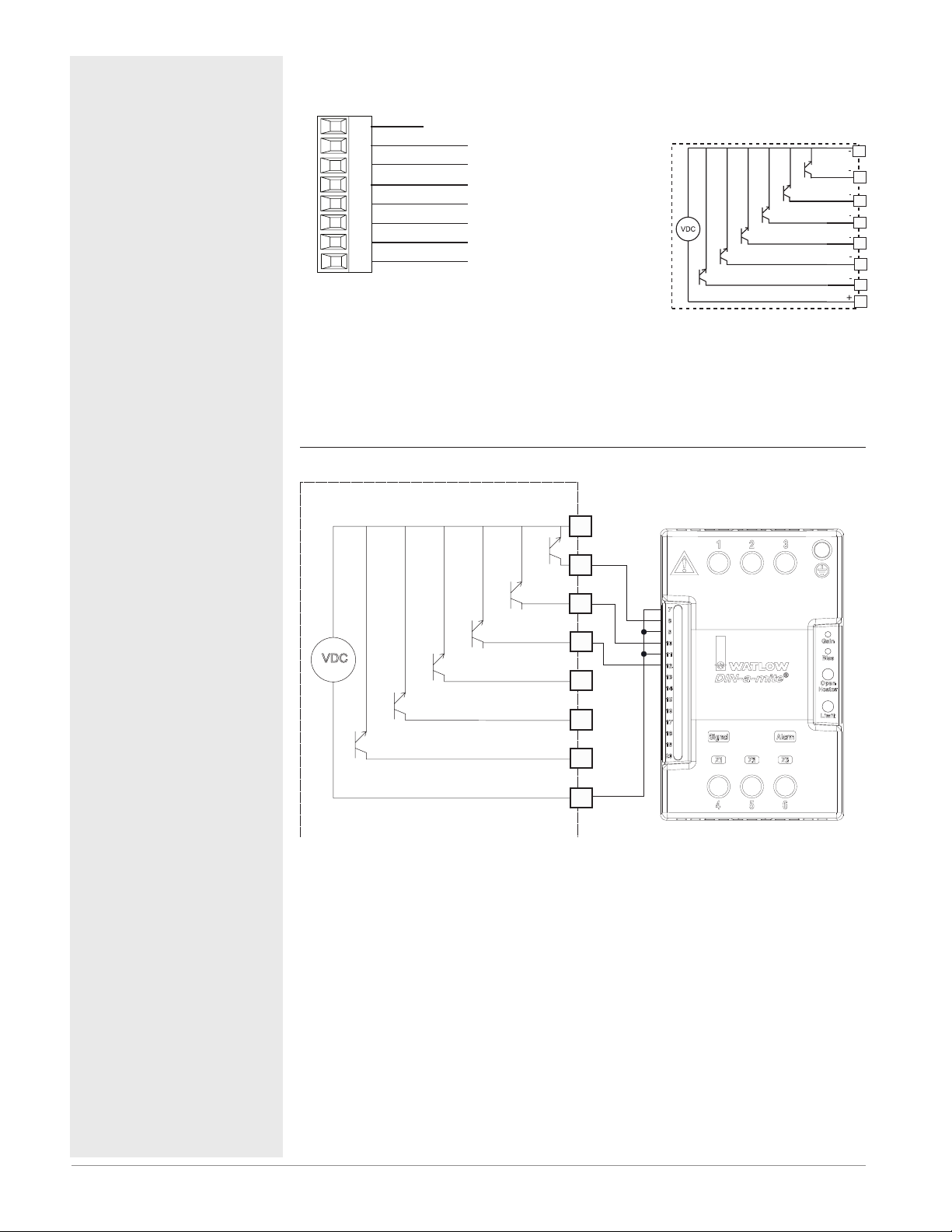
Digital Outputs 1 - 12
RMS Part # Digit 7, 8 is C
• Maximum switched voltage is 32VÎ (dc)
• Internal supply provides
a constant power output of 750mW
• Maximum output sink
current per output is
1.5A (external class 2 or
*SELV supply required)
• Total sink current for all
B_
D_
D_
D_
D_
D_
D_
Z_
Common
open collector/s
open collector/s
open collector/s
open collector/s
open collector/s
open collector/s
Internal
Supply
outputs not to exceed 8A
• Do not connect outputs in
parallel
- Slot D DO 1 - 6
RMSx-xx(C)x-xxxx
- Slot E DO 7 - 12
RMSx-xxx(C)-xxxx
*Safety Extra Low Voltage
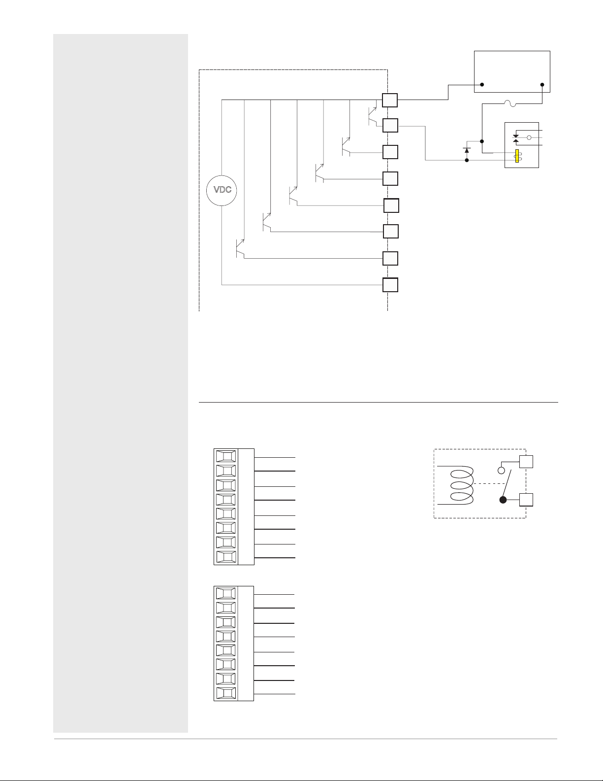
Switched DC Wiring Example Using DO 1-12
Collector Outputs
VDC
Internal Circuitry
Common
B_
D_
D_
D_
D_
D_
D_
Z_
Internal Supply
Htr 1
Htr 2
Htr 3
Open Collector/Switched
DC Outputs
+
-
+
-
+
-
DC90-60C0-0000
B_
D_
D_
D_
D_
Z_
Note:
As a switched DC output; this output is a constant current output delivering 750 mW, current limited to 400 mA. The internal supply does have a
maximum open circuit voltage of 22 VDC and minimum open circuit voltage of 19 VDC. Pin Z_ is shared to all digital outputs. This type of output is
meant to drive solid-state relays, not mechanical relays.
Suppressor Note:
Switching pilot duty inductive loads
(relay coils, solenoids, etc.) with the
mechanical relay, solid-state relay or
open collector output options requires
use of an R.C. suppressor for AC load or
a diode for a DC load.
Watlow EZ-ZONE® RMS Module • 26 • Chapter 2 Install and Wire
Page 30
Warning: ç
AGC-1 1/2
Slot D
Slot E
Use National Electric (NEC) or other
country-specific standard wiring and
safety practices when wiring and
connecting this controller to a power
source and to electrical sensors or peripheral devices. Failure to do so may
result in damage to equipment and
property, and/or injury or loss of life.
Note:
Maximum wire size termination and
torque rating:
• 0.0507 to 3.30 mm2 (30 to 12 AWG)
single-wire termination or two 1.31
mm2 (16 AWG)
• 0.8 Nm (7.0 in-lb.) torque
Note:
Adjacent terminals may be labeled
differently, depending on the model
number.
Open Collector Wiring Example Using DO 1-12
Collector Outputs
VDC
Common
B_
D_
D_
D_
D_
D_
D_
Diode
Power Supply
5 to 32 VDC
-
Fuse
+
An example fuse is
Bussmann
Relay
Note:
To prevent damage to the controller,
do not connect wires to unused terminals.
Note:
Maintain electrical isolation between
digital input-outputs, switched dc/open
collector outputs and process outputs
to prevent ground loops.
Warning: ç
Explosion Hazard – Substitution of
component may impair suitability for
CLASS I, DIVISION 2.
Warning: ç
Explosion Hazard - Do not disconnect
while the circuit is live or unless the
area is known to be free of ignitable
concentrations of flammable substances.
Suppressor Note:
Switching pilot duty inductive loads
(relay coils, solenoids, etc.) with the
mechanical relay, solid-state relay or
open collector output options requires
use of an R.C. suppressor for AC load or
a diode for a DC load.
Z_
Internal Circuitry
Internal Supply
As an open collector output (see graphic below), use an external power supply with the negative wired to B_, the positive to the coil of a pilot mechanical relay and the other side of the coil wired to the output of choice (D_).
Each open collector output can sink 1.5 A with the total for all open collector
outputs not exceeding 8 amperes. Ensure that a kickback diode is reversed
wired across the relay coil to prevent damage to the internal transistor.
Output 1 - 4 and 7 - 10 Mechanical Relay, Form A
RMS Part # Digit 7, 8 is J
Mechanical Relay Form A
L_
_
K
Internal Circuitry
L1
K1
L2
K2
L3
K3
L4
K4
L7
K7
L8
K8
L9
K9
L10
K10
normally open
common
normally open
common
normally open
common
normally open
common
normally open
common
normally open
common
normally open
common
normally open
common
• 5 A at 240VÅ (ac) or 30VÎ
(dc) maximum resistive
load
• 20 mA at 24V minimum
load
• 125 VA pilot duty @
120/240VÅ (ac), 25 VA at
24VÅ (ac)
• 100,000 cycles at rated load
• Output does not supply
power.
• for use with ac or dc
See Quencharc note.
- Slot D Outputs 1 - 6
RMSx-xx(J)x-xxxx
- Slot E Outputs 7 - 10
RMSx-xxx(J)-xxxx
Watlow EZ-ZONE® RMS Module • 27 • Chapter 2 Install and Wire
Page 31

Warning: ç
User Load
Slot C
Slot C
Use National Electric (NEC) or other
country-specific standard wiring and
safety practices when wiring and
connecting this controller to a power
source and to electrical sensors or peripheral devices. Failure to do so may
result in damage to equipment and
property, and/or injury or loss of life.
Note:
Maximum wire size termination and
torque rating:
• 0.0507 to 3.30 mm2 (30 to 12 AWG)
single-wire termination or two 1.31
mm2 (16 AWG)
• 0.8 Nm (7.0 in-lb.) torque
Note:
Adjacent terminals may be labeled
differently, depending on the model
number.
Note:
To prevent damage to the controller,
do not connect wires to unused terminals.
Note:
Maintain electrical isolation between
digital input-outputs, switched dc/open
collector outputs and process outputs
to prevent ground loops.
Quencharc Wiring Example
• In this example the Quencharc
circuit (Watlow part# 0804-0147-
0000) is used to protect internal
circuitry from the counter electromagnetic force from the inductive user load when deenergized.
It is recommended that this or
an equivalent Quencharc be used
when connecting inductive loads
to outputs.
Standard Bus EIA-485 Communications
• Wire T-/R- to the A terminal of the EIA-485 port.
• Wire T+/R+ to the B termi-
98 99 CF CD CE CZ CX CY
common
T-/R-
T+/R+
nal of the EIA-485 port.
• Wire common to the common terminal of the EIA485 port.
• Do not route network
wires with power wires.
Connect network wires in
daisy-chain fashion when
connecting multiple devices in a network.
L_
Quencharc
_
K
• A 120 Ω termination resistor may be required across
T+/R+ and T-/R-, placed on
the last controller on the
network.
• Do not connect more than
16 EZ-ZONE RM controllers on a network.
• maximum network length:
1,200 meters (4,000 feet)
• 1/8th unit load on EIA-485
bus
RMSx-xxxx-x(A)xx
* All models include Standard
Bus communications
N
Warning: ç
Explosion Hazard – Substitution of
component may impair suitability for
CLASS I, DIVISION 2.
Warning: ç
Explosion Hazard - Do not disconnect
while the circuit is live or unless the
area is known to be free of ignitable
concentrations of flammable substances.
Modbus RTU or Standard Bus EIA-485 Communications
98 99 CC CA CB CZ CX CY
Modbus-IDA
Terminal
DO A CA or CD T-/R-
D1 B CB or CE T+/R+
common common CC or CF common
common
T-/R-
T+/R+
EIA/TIA-485 Name Watlow Terminal
Note:
Do not leave a USB to EIA-485 converter connected to Standard Bus without power (i.e., disconnecting the USB end from the computer while leaving
the converter connected on Standard Bus). Disturbance on the Standard
Bus may occur.
• Wire T-/R- to the A terminal of the EIA-485 port.
• Wire T+/R+ to the B terminal of the EIA-485 port.
• Wire common to the common terminal of the EIA485 port.
• Do not route network wires
with power wires. Connect
network wires in daisychain fashion when connecting multiple devices in
a network.
• A termination resistor may
be required. Place a 120 Ω
resistor across T+/R+ and
T-/R- of last controller on
network.
Label
• Only one protocol per port
is available at a time: either Modbus RTU or Standard Bus.
• Do not connect more than
16 EZ-ZONE controllers on
a Standard Bus network.
• Maximum number of EZZONE controllers on a
Modbus network is 247.
• maximum network length:
1,200 meters (4,000 feet)
• 1/8th unit load on EIA-485
bus
RMSx-xxxx-x(1)xx
Function
Watlow EZ-ZONE® RMS Module • 28 • Chapter 2 Install and Wire
Page 32

USB
Port
PC Software Protocol - Standard Bus
EZ-Configurator
EZ-ZONE® RM
to B&B Converter
Model ULINX 485USBTB-2W
TM
USB to RS-485 Adapter
using Standard Bus
Use twisted pair wires such as Cat 5 cabling.
Do not route with power carrying conductors.
98 99
CF CD CE CZ CX CY
Data format
38,400 baud
8 data bits
no parity
1 start bit
1 stop bit
TM
U
S
U
B
B B electronics
Model 485TB-2W
LINX
USB Serial Conversion
&
0847-0326-0000
A(-)
B(+)
A(-)
B(+)
GND
R
EZ ZONE
DE
AB
98 99
CF CD CE CZ CX CY
RM
1
D
E
A
B
SM
9
1
10
2
3
11
4
12
5
13
6
14
7 15
16
8
C
t
o
l
S
USB
Port
PC Software Protocol - Modbus RTU
Third Party
EZ-ZONE® RM
to B&B Converter
Model ULINX 485USBTB-2W
TM
USB to RS-485 Adapter
using Modbus RTU
Use twisted pair wires such as Cat 5 cabling.
Do not route with power carrying conductors.
98 99
CC CA CB CZ CX CY
Data format
9,600, 19,200, 38,400 baud
8 data bits
even, odd, no parity
1 start bit
1 stop bit
TM
U
S
U
B
Model 485TB-2W
B B electronics
&
LINX
USB Serial Conversion
0847-0326-0000
A(-)
B(+)
A(-)
B(+)
GND
R
EZ ZONE
DE
AB
98 99
CC CA CB CZ CX CY
RM
1
D E
A
B
SM
9
1
10
2
3
11
4
12
5
13
6
14
7 15
16
8
C
t
o
l
S
Note:
Do not leave a USB to EIA-485 converter connected to Standard Bus without power (i.e., disconnecting the
USB end from the computer while leaving the converter connected on Standard Bus). Disturbance on the
Standard Bus may occur.
Watlow EZ-ZONE® RMS Module • 29 • Chapter 2 Install and Wire
Page 33

Wiring a Serial EIA-485 Network
Do not route network wires with power wires. Connect network wires in daisy-chain fashion when connecting multiple devices in a network.
A network using Watlow's Standard Bus and an RUI/Gate
way.
A termination resistor is required. Place a 120 Ω
resistor across T+/R+ and T-/R- of the last controller
on a network.
Only one protocol per port is available at a time:
either Modbus RTU or Standard Bus.
A network using Modbus RTU
EZ-ZONE
99
98
EZ-ZONE
CF
Slot C
CD
®
RMS
CX
CE
CY
CZ
®
PM
common
- A
+ B
RUI/Gateway
common
+ B
fuse
EZ-ZONE
®
RMS
fuse
Power
Supply
Slot C
CC
99
98
+ B
- A
co mmo n
98
99
CF
CD
CE
B5
D6
D5
98
99
CF
CD
- A
CE
EZ-ZONE
CX
CB
CZ
®
PM
common
CY
- A
+ B
PLC
common
+ B
common
98
99
CC
CA
CB
B5
D6
D5
common
- A
CA
Power
Supply
+ B
- A
+ B
- A
Watlow EZ-ZONE® RMS Module • 30 • Chapter 2 Install and Wire
Page 34

Connecting and Wiring the Modules
RMS Module Connections
The RMS module can be installed as a stand-alone
scanner or can be interconnected on the DIN rail as
shown below with other RM family modules. When
modules are connected together as shown, power and
communications are shared between modules over
the modular backplane interconnection. Therefore,
bringing the necessary power and communications
wiring to any one connector in slot C is sufficient.
The modular backplane interconnect comes standard
with every module ordered and is generic in nature,
meaning any RM modules shown below on the DIN
Modular backplane interconnect
rail can use it.
Notice in the split rail system diagram that a
single power supply is being used across both DIN
rails. One notable consideration when designing the
hardware layout would be the available power supplied and the loading affect of all of the modules
used. Watlow provides three options for power supplies listed below:
1. 90-264 Vac to 24Vdc @ 31 watts (Part #: 08470299-0000)
2. 90-264 Vac to 24Vdc @ 60 watts (Part #: 08470300-0000)
3. 90-264 Vac to 24Vdc @ 91 watts (Part #: 08470301-0000)
With regards to the modular loading affect, maximum power for each RM module is listed below:
1. RMCxxxxxxxxxxxx @ 7 watts / 14VA
2. RMEx-xxxx-xxxx @ 7 watts / 14VA
3. RMAx-xxxx-xxxx @ 4 watts / 9VA
4. RMLx-xxxx-xxxx @ 7 watts / 14VA
5. RMSx-xxxx-xxxx @ 7 watts / 14VA
6. RMHx-xxxx-xxxx @ 7 watts / 14VA
So, in the split rail system diagram, the maximum
current draw on the supply would be 38 Watts.
- 2 RMC modules consumes 14W
- 1 RMS module consumes 7W
- 1 RME modules consumes 7W
- 1 RMA module consumes 4W
- 1 Remote User Interface consumes 6W
With this power requirement (38 watts) the second or
third power supply could be used.
Another hardware configuration scenario that could
present itself (graphic not shown) would be a configuration that requires more than one supply. Lets
make some assumptions pertaining to the split rail
system diagram shown below. The power supply
used is the 91W supply. The top DIN rail now has
the following modules:
- 2 RMC modules consumes 14W
- 1 RMA consumes 4W
- 11 RME modules consumes 77W
- 2 RMS modules consumes 14W
As can now be seen, the total power requirement
exceeds 91W. In this case, another power supply
would be required. To incorporate another supply in
this system simply disconnect pins 99 and 98 on the
remote DIN rail and connect another appropriately
sized power supply for the remote modules to those
same pins.
When using a split rail configuration ensure that
the interconnections for the Inter-module Bus and
Standard Bus do not exceed 200 feet. Standard Bus
and the Inter-module Buses are different protocols
and both are required for split rail configurations.
Without having both connected communications between modules would not be possible.
RMAx-xxxx-xxx
Slot D
Slot E
_
_
_
_
_
_
_
_
_
_
_
_
_
_
_
_
Slot B
Slot A
_
_
_
_
_
_
_
_
_
_
_
_
_
_
_
_
CX
CE
CY
CZ
98
RMEx-xxxx-xxxx
_
_
_
Standard Bus
_
_
Address 5
_
_
_
_
_
_
_
_
_
_
_
Slot C
CD
CE
CZ
CF
99
98
CD
CE
RM Access
Module
Standard Bus
Address 3
Slot C
CD
CE
CF
99
Slot E
_
_
_
_
_
_
_
_
Slot B
_
_
_
_
_
_
_
_
CX
CY
Slot E
_
_
_
_
_
_
_
_
Slot B
_
_
_
_
_
_
_
_
CX
CY
CZ
Inter-module
Bus
Standard Bus
Low Voltage
Class 2
Power Supply
CE
Slot E
_
_
_
_
_
_
_
_
Slot B
_
_
_
_
_
_
_
_
CX
CZ
RM Scanner
Module
RMSx-xxxx-xAxx
Slot D
_
_
_
Standard Bus
_
Address 2
_
_
_
_
Slot A
_
_
_
_
_
_
_
_
CF
CY
99
98
RM Controller
Module
RMCxxxxxxxxxAxx
Slot D
_
_
_
Standard Bus
_
Address 1
_
_
_
_
Slot A
_
_
_
_
_
_
_
_
Slot C
CD
CF
99
98
Split Rail Configuration
RM Controller
Module
RMCxxxxxxxxxAxx
Slot A
Slot D
_
_
_
Standard Bus
_
_
Address 4
_
_
_
_
_
_
_
_
_
_
_
Slot C
CD
CF
99
98
EZKB-_ A _ _- _ _ _ _
Slot E
_
_
_
_
_
_
_
_
Slot B
_
_
_
_
_
_
_
_
CX
CE
CY
CZ
RUI
98
99
Slot C
CD
Standard Bus
RM Expansion
Module
Slot D
Slot A
CF
Note:
Unit is not provided with a disconnect, use of an
external disconnect is required. It should be located
in close proximity to the unit and be labeled as the
disconnect for the unit.
Watlow EZ-ZONE® RMS Module • 31 • Chapter 2 Install and Wire
Page 35

Conventions Used in the Menu Pages
To better understand the menu pages that follow
review the naming conventions used. When encountered throughout this document, the word "default"
implies as shipped from the factory. Each page (Operations, Setup and Factory) and their associated
menus have identical headers defined below:
Header Name Definition
Display
Parameter Name
Range
Default
Modbus Relative Address
CIP (Common Industrial Protocol)
Profibus Index
Parameter ID
Data Type R/W
Remote User interface (RUI) Display
Visual information from the control is displayed to
the observer using a fairly standard 7 segment display. Due to the use of this technology, several characters displayed need some interpretation, see the
list below:
Watlow EZ-ZONE® RMH Module • 32 • Chapter 2 Menu Conventions
Visually displayed information from the control.
Describes the function of
the given parameter.
Defines options available
for this prompt, i.e., min/
max values (numerical),
yes/no, etc... (further explanation below).
Values as delivered from
the factory.
Identifies unique parameters using either the
Modbus RTU or Modbus
TCP protocols (further explanation below).
Identifies unique parameters using either the DeviceNet or EtherNet/IP
protocol (further explanation below).
Identifies unique parameters using Profibus DP
protocol (further explanation below).
Identifies unique parameters used with other software such as, LabVIEW.
uint = Unsigned 16 bit
integer
dint = long, 32-bit
string = ASCII (8 bits
per character)
float = IEEE 754 32-bit
RWES = Readable
Writable
EEPROM (saved)
User Set (saved)
[1] = 1 [0] = 0 [i] = i [ r] = r
[2] = 2 [a] = A [j] = J [S] = S
[3] = 3 [b] = b [H] = K [t] = t
[4] = 4 [c] , [C] = c [l] = L [U] = u
[5] = 5 [d ] = d [m] = M [u] = v
[6] = 6 [e] = E [n] = n [w ] = W
[7] = 7 [f] = F [o] = o [y ] = y
[8] = 8 [g] = g [p] = P [2] = Z
[9] = 9 [h] = h [ q ] = q
Note:
The RUI is optional equipment.
Range
Within this column notice that on occasion there will
be numbers found within parenthesis. This number
represents the enumerated value for that particular
selection. Range selections can be made simply by
writing the enumerated value of choice using any of
the available communications protocols. As an example, turn to the Setup Page and look at the Analog
Input [`Ai] menu and then the Sensor Type [Sen]
prompt. To turn the sensor off simply write the value
of 62 (off) to Modbus register 388 and send that value
to the control.
Communication Protocols and Software Tools
All RM modules come with Watlow's Standard
Bus protocol. This protocol is used primarily for
inter-module communications but is also used with
SpecView by Watlow, LabVIEW and EZ-ZONE Configurator software (free download from Watlow's web
site (http://www.watlow.com). Along with Standard
Bus, the RMS module can also be ordered with Modbus RTU (only one protocol can be active at any given
time). The RMA (Access) module has options for several different protocols listed below:
- Modbus RTU 232/485
- EtherNet/IP, Modbus TCP
- DeviceNet
- Profibus DP
Modbus RTU Protocol
All Modbus registers are 16-bits and as displayed
in this manual are relative addresses (actual). Some
legacy software packages limit available Modbus registers to 40001 to 49999 (5 digits). Many applications
today require access to all available Modbus registers
which range from 400001 to 465535 (6 digits). Watlow EZ-ZONE controllers support 6 digit Modbus registers. For parameters listed as f loat notice that only
one (low order) of the two registers is listed, this is
true throughout this document. By default the low order word contains the two low bytes of the 32-bit parameter. As an example, look in the Operations Page
for the Process Value. Find the column identified in
Page 36

the header as Modbus and notice that it lists register
380. Because this parameter is a float it is actually
represented by registers 381 (low order bytes) and
381 (high order bytes). Because the Modbus specification does not dictate which register should be high
or low order Watlow provides the user the ability to
swap this order (Setup Page, Com Menu) from the
default low/ high [lohi] to high/low [hilo].
It should also be noted that some of the cells in the
Modbus column contain wording pertaining to an offset. Several parameters in the control contain more
than one instance; such as, alarms (24), analog inputs (16), etc... The Modbus register shown always
represents instance one. Take for an example the
Alarm Silencing parameter found in the Setup Page
under the Alarm menu. Instance one is shown as address 2670 and +60 is identified as the offset to the
next instance. If there was a desire to read or write
to the same member instance 3, simply add 120 to
2670 to find its address; in this case, the instance 3
address for Alarm Silencing is 2790.
To learn more about the Modbus protocol point
your browser to http://www.modbus.org.
Note:
There are two columns shown in the menus that
follow for communications protocols identified as
CIP (Common Industrial Protocol) and Profibus.
These columns will be useful if this control is used
in conjunction with the RMA module or the EZZONE Remote User Interface/Gateway (RUI/GTW)
where those protocols can be selected as optional
hardware. For this module (RMS), as a secondary
protocol beyond Standard Bus, Modbus RTU can be
ordered as optional hardware.
To learn more about the RUI/GTW point your
browser to the link below and search for keyword
EZ-ZONE.
http://www.watlow.com/literature/pti_search.cfm
Watlow EZ-ZONE® RMH Module • 33 • Chapter 2 Menu Conventions
Page 37

3
Chapter 3: Operations Pages
Navigating the Operations Page
To navigate to the Operations Page using the RUI, follow the steps below:
1. From the Home Page, press both the Up ¿ and
Down ¯ keys for three seconds. [``Ai] will appear
in the upper display and [oPEr] will appear in the
lo wer displ ay.
2. Press the Up ¿ or Down ¯ key to view available
menus.
3. Press the Advance Key ‰ to enter the menu of
choice.
4. If a submenu exists (more than one instance), press
the Up ¿ or Down ¯ key to select and then press
the Advance Key ‰ to enter.
5. Press the Up ¿ or Down ¯ key to move through
available menu prompts.
6. Press the Infinity Key ˆ to move backwards
through the levels: parameter to submenu; submenu
to menu; menu to Home Page.
7. Press and hold the Infinity Key ˆ for two seconds to
return to the Home Page.
On the following pages, top level menus are identified
with a yellow background color.
Note:
Some of these menus and parameters may not appear, depending on the controller's options. See model
number information in the Appendix for more information. If there is only one instance of a menu, no submenus will appear.
Note:
Some of the listed parameters may not be visible. Parameter visibility is dependent upon controller part
number.
[``Ai]
[oPEr] Analog Input Menu
[```1]
[``Ai] Analog Input (1 to 16)
[`Ain] Analog Input Value
[`i;Er] Input Error
[`i;Ca] Calibration Offset
[``Pu]
[oPEr] Process Value Menu
[```1]
[``Pu] Process Value (1 to 16)
[`Su;A] Source Value A
[`Su;b] Source Value B
[`Su;c] Source Value C
[`Su;d] Source Value D
[`Su;E] Source Value E
[oFSt] Offset
[``o;u] Output Value
[`dio]
[oPEr] Digital Input/Output Menu
[```1] to [``12]
[`dio] Digital I/O (1 to 12)
[`do;S] Output State
[`di;S] Input State
[aCt]
[oPEr] Action Menu
[```1]
[aCt] Action (1 to 16)
[`ei;S] Event Status
[ALM]
[oPEr] Alarm Menu
[```1]
[ALM] Alarm (1 to 16)
[`A;Lo] Alarm Low Set Point
[`A;hi] Alarm High Set Point
[a;Clr] Alarm Clear Request
[a;sir] Alarm Silence Request
[`A;st] State
[[`Lnr]
[oPEr] Linearization Menu
[```1]
[`Lnr] Linearization (1 to 24)
[`Su;A] Source Value A
[oFSt] Offset
[``o;u] Output Value
[`CPE]
[oPEr] Compare Menu
[```1]
[`CPE] Compare (1 to 24)
[`Su;A] Source Value A
[`Su;b] Source Value B
[``o;u] Output Value
[tMr]
[oPEr] Timer Menu
[```1]
[tMr] Timer (1 to 24)
[`Su;A] Source Value A
[`Su;b] Source Value B
[``E;t] Elapsed Time
[``o;u] Output Value
[`Ctr]
[oPEr] Counter Menu
[```1]
[`Ctr] Counter (1 to 24)
[`Cnt] Count
[`Su;A] Source Value A
[`Su;b] Source Value B
[``o;u] Output Value
[`LgC]
[oPEr] Logic Menu
[```1]
[`LgC] Logic (1 to 24)
[`Su;A] Source Value A
[`Su;b] Source Value B
[`Su;C] Source Value C
[`Su;d] Source Value D
[`Su;E] Source Value E
[`Su;F] Source Value F
[`Su;g] Source Value G
[`Su;h] Source Value H
[``o;u] Output Value
[MAt]
[oPEr] Math Menu
[```1]
[MAt] Math (1 to 24)
[`Su;A] Source Value A
[`Su;b] Source Value B
[`Su;C] Source Value C
[`Su;d] Source Value D
[`Su;E] Source Value E
[oFSt] Offset
[``o;u] Output Value
Watlow EZ-ZONE® RMS Module • 34 • Chapter 3 Operations Page
Page 38

RM Scanner Module • Operations Page
Display
Parameter Name
Description
Range Default
[``Ai]
[oPEr]
Analog Input Menu
[``Ain]
[ Ain]
Analog Input (1 to 16)
Input Value
View the process value.
-1,999.000 to 9,999.000°F
or units
-1,128.000 to 5,537.000°C
- - - - 380
Note:
Ensure that the Error
Status (below) indicates
no error (61) when reading this value using a
field bus protocol. If an
error exists, the last
known value prior to the
error occurring will be
returned.
No Display
Analog Input (1 to 16)
Filtered Process Value
View the process value
-1,999.000 to 9,999.000°F
or units
-1,128.000 to 5,537.000°C
- - - - 422
when filtering is turned on.
[`i;Er]
[ i.Er]
Analog Input (1 to 16)
Input Error
View the cause of the most
recent error.
[nonE] None (61)
[OPEn] Open (65)
[Shrt] Shorted (127)
[`E;M] Measurement Error
None 382
(140)
[E;CAL] Bad Calibration
Data (139)
[Er;Ab] Ambient Error (9)
[E;;Rtd] RTD Error (141)
[FAiL] Fail (32)
[Nsrc] Not Sourced (246)
[`i;Ca]
[ i.CA]
Analog Input (1 to 16)
Calibration Offset
Offset the input reading to
-1,999.000 to 9,999.000°F
or units
-1,110.555 to 5,555.000°C
0.0 402
compensate for lead wire
resistance or other factors
that cause the input reading to vary from the actual
process value.
No Display
Analog Input (1 to 16)
Clear Latched Input Er-
Clear Latch (1221) - - - - 436
ror
Clear latched input when
input error condition no
longer exists.
[``Pu]
[oPEr]
Process Value Menu
[`Su;A]
[ Sv.A]
[`Su;b]
[ Sv.b]
Process Value (1 to 16)
Source Value A
View the value of Source A.
Process Value (1 to 16)
Source Value B
View the value of Source B.
-1,999.000 to 9,999.000°F
or units
-1,110.556 to 5,555.000°C
-1,999.000 to 9,999.000°F
or units
-1,110.556 to 5,555.000°C
- - - - 5210
- - - - 5212
Note: Some values will be rounded off to fit in the four-character display. Full values
can be read with other interfaces.
If there is only one instance of a menu, no submenus will appear.
Modbus
Relative
Address
[offset 90]
[offset 90]
[offset 90]
[offset 90]
[offset 90]
[offset 70]
[offset 70]
CIP
Class
Instance
Attribute
hex (dec)
0x68 (104)
1 to 0x10
(16)
1
0x68 (104)
1 to 0x10
(16)
0x16 (22)
0x68 (104)
1 to 0x10
(16)
2
0x68 (104)
1 to 0x10
(16)
0xC (12)
0x68 (104)
1 to 0x10
(16)
0x1D (29)
0x7E (126)
1 to 0x10
(16)
0x10 (16)
0x7E (126)
1 to 0x10
(16)
0x11 (17)
Probus
Index
Parameter
ID
0 4001 float
- - - - 4022 float
1 4002 uint
2 4012 float
- - - - 4029 uint
- - - - 26016 float
- - - - 26017 float
Data
Type
& Read/
Write
R
R
R
RWES
W
R
R
R: Read
W: Write
E: EEPROM
S: User Set
Watlow EZ-ZONE® RMS Module • 35 • Chapter 3 Operations Page
Page 39

RM Scanner Module • Operations Page
Display
[`Su;c]
[ Sv.c]
[`Su;d]
[ Sv.d]
[`Su;E]
[ Sv.E]
[oFSt]
[oFSt]
Parameter Name
Description
Process Value (1 to 16)
Source Value C
View the value of Source C.
Process Value (1 to 16)
Source Value D
View the value of Source D.
Process Value (1 to 16)
Source Value E
View the value of Source E.
Process Value (1 to 16)
Offset
Set an offset to be applied
Range Default
-1,999.000 to 9,999.000°F
or units
-1,110.556 to 5,555.000°C
-1,999.000 to 9,999.000°F
or units
-1,110.556 to 5,555.000°C
-1,999.000 to 9,999.000°F
or units
-1,110.556 to 5,555.000°C
-1,999.000 to 9,999.000°F
or units
-1,110.556 to 5,555.000°C
- - - - 5214
- - - - 5216
- - - - 5218
0 5224
to this function's output.
[``o;u]
[ o.v]
Process Value (1 to 16)
Output Value
View the value of this func-
-1,999.000 to 9,999.000°F
or units
-1,110.556 to 5,555.000°C
0.0 5222
tion block's output.
No Display
Process Value (1 to 16)
Error
View reported cause for
Linearization output malfunction.
None (61)
Open (65)
Shorted (127)
Measurement error (140)
Bad calibration data (139)
None 5232
Ambient error (9)
RTD error (14)
Fail (32)
Math error (1423)
Not sourced (246)
Stale (1617)
[`dio]
[oPEr]
Digital Input/Output Menu
[`do;S]
[ do.S]
Digital Output (1 to 12)
Output State
View the state of this out-
[`off] Off (62)
[``on] On (63)
put.
[`di;S]
[ di.S]
No Display
Digital Input (1 to 12)
Input State
View this event input state.
Digital Input (1 to 12)
Error
View reported cause for
digital input/output malfunction.
[`off] Off (62)
[``on] On (63)
None (61)
Open (65)
Shorted (127)
Measurement error (140)
Bad calibration data (139)
None 1848
Ambient error (9)
RTD error (14)
Fail (32)
Math error (1423)
Not sourced (246)
Stale (1617)
Note: Some values will be rounded off to fit in the four-character display. Full values
can be read with other interfaces.
If there is only one instance of a menu, no submenus will appear.
Modbus
Relative
Address
[offset 70]
[offset 70]
[offset 70]
[offset 70]
[offset 70]
[offset 70]
1832
[offset 30]
1840
[offset 30]
[offset 30]
CIP
Class
Instance
Attribute
hex (dec)
0x7E (126)
1 to 0x10
(16)
0x12 (18)
0x7E (126)
1 to 0x10
(16)
0x13 (19)
0x7E (126)
1 to 0x10
(16)
0x14 (20)
0x7E (126)
1 to 0x10
(16)
0x17 (23)
0x7E (126)
1 to 0x10
(16)
0x16 (22)
0x7E
(126)
1 to 0x10
(16)
0x1B (27)
0x6A (106)
1 to 0x0c
(12)
7
0x6A (106)
1 to 0x0c
(12)
0xB (11)
0x6A
(106)
1 to 0x0c
(12)
15
Probus
Index
Parameter
ID
- - - - 26018 float
- - - - 26019 float
- - - - 26020 float
- - - - 26023 float
- - - - 26022 float
- - - - 26027 uint
46 6007 uint
- - - - 6011 uint
- - - - 6015 uint
Data
Type
& Read/
Write
R
R
R
RWES
R
R
R
R
R
R: Read
W: Write
E: EEPROM
S: User Set
Watlow EZ-ZONE® RMS Module • 36 • Chapter 3 Operations Page
Page 40

RM Scanner Module • Operations Page
Display
Parameter Name
Description
Range Default
[`ACt]
[oPEr]
Action Menu
[`Ei;S]
[ Ei.S]
No Display
Action (1 to 16)
Event Input Status
View this input state.
Function Key (1)
Function Key State
[`off] Off (62)
[``on] On (63)
Off (62)
On (63)
- - - - - - - - - - - - - - - - 3024 uint
View current state of function key 1.
No Display
Function Key (2)
Function Key State
Off (62)
On (63)
- - - - - - - - - - - - - - - - 3030 uint
View current state of function key 2.
[ALM]
[oPEr]
Alarm Menu
[`A;Lo]
[ A.Lo]
Alarm (1 to 16)
Low Set Point
If Alarm Type (Setup
Page, Alarm Menu) is
-1,999.000 to 9,999.000°F
or units
-1,128.000 to 5,537.000°C
32.0 °F
or
units
0.0°C
set to:
process - set the process
value that will trigger a
low alarm.
[`A;hi]
[ A.hi]
Alarm (1 to 16)
High Set Point
If Alarm Type (Setup
Page, Alarm Menu) is
-1,999.000 to 9,999.000°F
or units
-1,128.000 to 5,537.000°C
300.0°F
or
units
150.0°C
set to:
process - set the process
value that will trigger a
high alarm.
[A;Clr]
[ A.hi]
Alarm (1 to 16)
Clear Request
Clear (129)
Ignore (204)
Ignore - - - - - - - - - - - - 9026
User interface (RUI) access to clear an alarm
[A;sir]
[A.Sir]
Alarm (1 to 16)
Silence Request
Ignore (204)
Silence (108)
Ignore - - - - - - - - - - - - 9027
User interface (RUI) access to silence an alarm
[`A;st]
[ A.St]
Alarm (1 to 16)
State
View state of alarm
Startup (88)
None (61)
Blocked (12)
Startup 2516
Alarm low (8)
Alarm high (7)
Error (28)
No Dis-
play
Alarm (1 to 16)
Latched
No (59)
Yes (106)
No 2518
Read this register to determine if the alarm is
latched
Note: Some values will be rounded off to fit in the four-character display. Full values
can be read with other interfaces.
If there is only one instance of a menu, no submenus will appear.
Modbus
Relative
Address
2188
[offset 20]
2502
[offset 60]
2500
[offset 60]
[offset 60]
[offset 60]
CIP
Class
Instance
Attribute
hex (dec)
0x6E (110)
1 to 0x10
(16)
5
0x6D
(109)
1 to 0x10
(16)
2
0x6D
(109)
1 to 0x10
(16)
1
0x6D
(109)
1 to 0x10
(16)
9
0x6D
(109)
1 to 0x10
(16)
0x0A (10)
Probus
Index
Parameter
ID
81 10005 uint
18 9002 float
19 9001 float
- - - - 9009 uint
- - - - 9010
Data
Type
& Read/
Write
R
R
R
RWES
RWES
uint
RW
uint
RW
R
uint
R
R: Read
W: Write
E: EEPROM
S: User Set
Watlow EZ-ZONE® RMS Module • 37 • Chapter 3 Operations Page
Page 41

RM Scanner Module • Operations Page
Display
No Dis-
play
Parameter Name
Description
Alarm (1 to 16)
Silenced
No (59)
Yes (106)
Range Default
None 2520
Read this register to determine if the alarm is
silenced
No Dis-
play
Alarm (1 to 16)
Clearable
No (59)
Yes (106)
None 2522
Read to determine if an
alarm can be cleared
No Dis-
play
Alarm (1 to 16)
Clear Request
Clear (0)
No Change (255)
None 2524
Write to this register to
clear an alarm
No Dis-
play
Alarm (1 to 16)
Silence Request
Clear (0)
No Change (255)
None 2526
Write to this register to
silence an alarm
No Dis-
play
Alarm (1 to 16)
Alarm Working Process
Value
-1,999.000 to 9,999.000°F
or units
-1,128.000 to 5,537.000°C
None 2536
Read process value used
by alarms
No Dis-
play
Alarm (1 to 16)
Alarm Working Set
Point
-1,999.000 to 9,999.000°F
or units
-1,128.000 to 5,537.000°C
None 2538
Read set point used by
alarms
No Dis-
play
Alarm (1 to 16)
Output Value
On (63)
Off (62)
None 2546
Read state of alarm output
[`Lnr]
[oPEr]
Linearization Menu
[`Su;A]
[ Su.A]
Linearization (1 to 24)
Source Value A
View the value of Source
-1,999.000 to 9,999.000°F
or units
-1,128.000 to 5,537.000°C
A.
[oFSt]
[oFSt]
Linearization (1 to 24)
Offset
Set an offset to be applied
-1,999.000 to 9,999.000°F
or units
-1,128.000 to 5,537.000°C
0 11350
to this function's output.
[``o;u]
[ o.v]
Linearization (1 to 24)
Output Value
View the value of this
-1,999.000 to 9,999.000°F
or units
-1,128.000 to 5,537.000°C
function's output.
Note: Some values will be rounded off to fit in the four-character display. Full values
can be read with other interfaces.
If there is only one instance of a menu, no submenus will appear.
Modbus
Relative
Address
[offset 60]
[offset 60]
[offset 60]
[offset 60]
[offset 60]
[offset 60]
[offset 60]
11346
[offset 70]
[offset 70]
11352
[offset 70]
CIP
Class
Instance
Attribute
hex (dec)
0x6D
(109)
1 to 0x10
(16)
0x0B (11)
0x6D
(109)
1 to 0x10
(16)
0xC (12)
0x6D
(109)
1 to 0x10
(16)
0xD (13)
0x6D
(109)
1 to 0x10
(16)
0x0E (14)
0x6D
(109)
1 to 0x10
(16)
0x13 (19)
0x6D
(109)
1 to 0x10
(16)
0x14 (20)
0x6D
(109)
1 to 0x10
(16)
0x18 (24)
0x86
(134)
1 to 0x18
(24)
4
0x86
(134)
1 to 0x18
(24)
6
0x86
(134)
1 to 0x18
(24)
7
Probus
Index
Parameter
ID
- - - - 9011
- - - - 9012 uint
32 9013
33 9014
- - - - 9019
- - - - 9020
- - - - 9024
- - - - 34004 float
- - - - 34006 float
- - - - 34007 float
Data
Type
& Read/
Write
uint
R
R
uint
RW
uint
RW
float
R
float
R
uint
R
R
RWES
R
R: Read
W: Write
E: EEPROM
S: User Set
Watlow EZ-ZONE® RMS Module • 38 • Chapter 3 Operations Page
Page 42

RM Scanner Module • Operations Page
Display
No Display
Parameter Name
Description
Linearization (1 to 24)
Error
Read reported cause for
linearization error
Range Default
None (61)
Open (65)
Shorted (127)
Measurement Error (140)
Bad Cal Data (139)
Ambient Error (9)
RTD Error (141)
Fail (32)
Math Error (1423)
Not Sourced (246)
Stale (1617)
[`CPE]
[oPEr]
Compare Menu
[`Su;A]
[ Su.A]
Compare (1 to 24)
Source Value A
View the value of Source
-1,999.000 to 9,999.000°F
or units
-1,128.000 to 5,537.000°C
A.
[`Su;b]
[ Su.b]
Compare (1 to 24)
Source Value B
View the value of Source
-1,999.000 to 9,999.000°F
or units
-1,128.000 to 5,537.000°C
B.
[``o;u]
[ o.v]
Compare (1 to 24)
Output Value
View the value of this
[`off] Off (62)
[``on] On (63)
function's output.
No Display
Compare (1 to 24)
Error
Read reported cause for
compare error
None (61)
Open (65)
Shorted (127)
Measurement Error (140)
Bad Cal Data (139)
Ambient Error (9)
RTD Error (141)
Fail (32)
Math Error (1423)
Not Sourced (246)
Stale (1617)
[tMr]
[oPEr]
Timer Menu
[`Su;A]
[ Su.A]
Timer (1 to 24)
Value Source A
View the value of Source
[`off] Off (62)
[``on] On (63)
- - - - 10152
A.
[`Su;b]
[ Su.b]
Timer (1 to 24)
Value Source B
View the value of Source
[`off] Off (62)
[``on] On (63)
- - - - 10154
B.
Note: Some values will be rounded off to fit in the four-character display. Full values
can be read with other interfaces.
If there is only one instance of a menu, no submenus will appear.
Modbus
Relative
Address
11394
[offset 70]
8232
[offset 40]
8234
[offset 40]
8238
[offset 40]
8244
[offset 40]
[offset 50]
[offset 50]
CIP
Class
Instance
Attribute
hex (dec)
0x86
(134)
1 to 0x18
(24)
0x1C (28)
0x80
(128)
1 to 0x18
(24)
7
0x80
(128)
1 to 0x18
(24)
8
0x80
(128)
1 to 0x18
(24)
0xA (10)
0x80
(128)
1 to 0x18
(24)
0x0D (13)
0x83
(131)
1 to 0x18
(24)
7
0x83
(131)
1 to 0x18
(24)
8
Probus
Index
Parameter
ID
- - - - 34028 uint
- - - - 28007 float
- - - - 28008 float
- - - - 28010 uint
- - - - 28013 uint
- - - - 31007 uint
- - - - 31008 uint
Data
Type
& Read/
Write
R
R
R
R
R
R
R
R: Read
W: Write
E: EEPROM
S: User Set
Watlow EZ-ZONE® RMS Module • 39 • Chapter 3 Operations Page
Page 43

RM Scanner Module • Operations Page
Display
[``E;t]
[ E.t]
Parameter Name
Description
Timer (1 to 24)
Elapsed Time
Range Default
0 to 30,000.0 seconds 0 10170
View the value of this
function's elapsed time.
[``o;u]
[ o.v]
Timer (1 to 24)
Output Value
View the value of this
[`off] Off (62)
[``on] On (63)
- - - - 10158
function's output.
No Display
Timer (1 to 24)
Running
Off (62)
On (63)
- - - - 10168
Read to determine if timer
is running
No Display
Timer (1 to 24)
Error
Read reported cause for
timer error
None (61)
Open (65)
Shorted (127)
Measurement Error (140)
Bad Cal Data (139)
Ambient Error (9)
RTD Error (141)
Fail (32)
Math Error (1423)
Not Sourced (246)
Stale (1617)
[`Ctr]
[oPEr]
Counter Menu
[`Cnt]
[ Cnt]
Counter (1 to 24)
Count
0 to 9,999 9208
View the function's total
count.
[`Su;A]
[ Su.A]
Counter (1 to 24)
Source Value A
View the value of Source
[`off] Off (62)
[``on] On (63)
A.
[`Su;b]
[ Su.b]
Counter (1 to 24)
Source Value B
View the value of Source
[`off] Off (62)
[``on] On (63)
B.
[``o;u]
[ o.v]
Counter (1 to 24)
Output Value
View the value of this
[`off] Off (62)
[``on] On (63)
function's output.
Note: Some values will be rounded off to fit in the four-character display. Full values
can be read with other interfaces.
If there is only one instance of a menu, no submenus will appear.
Modbus
Relative
Address
[offset 50]
[offset 50]
[offset 50]
10174
[offset 50]
[offset 40]
9192
[offset 40]
9194
[offset 40]
9198
[offset 40]
CIP
Class
Instance
Attribute
hex (dec)
0x83
(131)
1 to 0x18
(24)
0x10 (16)
0x83
(131)
1 to 0x18
(24)
0x11 (17)
0x83
(131)
1 to 0x18
(24)
0x0F (15)
0x83
(131)
1 to 0x18
(24)
0x12 (18)
0x82
(130)
1 to 0x18
(24)
0xF (15)
0x82
(130)
1 to 0x18
(24)
7
0x82
(130)
1 to 0x18
(24)
8
0x82
(130)
1 to 0x18
(24)
0xA (10)
Probus
Index
Parameter
ID
- - - - 31016 float
- - - - 31010 uint
- - - - 31015 uint
- - - - 31018 uint
125 30015 uint
- - - - 30007 uint
- - - - 30008 uint
- - - - 30010 uint
Data
Type
& Read/
Write
R
R
R
R
R
R
R
R
R: Read
W: Write
E: EEPROM
S: User Set
Watlow EZ-ZONE® RMS Module • 40 • Chapter 3 Operations Page
Page 44

RM Scanner Module • Operations Page
Display
No Display
Parameter Name
Description
Counter (1 to 24)
Error
Read reported cause for
counter error
Range Default
None (61)
Open (65)
Shorted (127)
Measurement Error (140)
Bad Cal Data (139)
Ambient Error (9)
RTD Error (141)
Fail (32)
Math Error (1423)
Not Sourced (246)
Stale (1617)
[`LgC]
[oPEr]
Logic Menu
[`Su;A]
[ Su.A]
Logic (1 to 24)
Source Value A
View the value of Source
[`off] Off (62)
[``on] On (63)
A.
[`Su;b]
[ Su.b]
Logic (1 to 24)
Source Value B
View the value of Source
[`off] Off (62)
[``on] On (63)
B.
[`Su;C]
[ Su.C]
Logic (1 to 24)
Source Value C
View the value of Source
[`off] Off (62)
[``on] On (63)
C.
[`Su;d]
[ Su.d]
Logic (1 to 24)
Source Value D
View the value of Source
[`off] Off (62)
[``on] On (63)
D.
[`Su;E]
[ Su.E]
Logic (1 to 24)
Source Value E
View the value of Source
[`off] Off (62)
[``on] On (63)
E.
[`Su;F]
[ Su.F]
Logic (1 to 24)
Source Value F
View the value of Source
[`off] Off (62)
[``on] On (63)
F.
[`Su;g]
[ Su.g]
Logic (1 to 24)
Value Source G
View the value of Source
[`off] Off (62)
[``on] On (63)
G.
[`Su;h]
[ Su.h]
Logic (1 to 24)
Source Value H
View the value of Source
[`off] Off (62)
[``on] On (63)
H.
Note: Some values will be rounded off to fit in the four-character display. Full values
can be read with other interfaces.
If there is only one instance of a menu, no submenus will appear.
Modbus
Relative
Address
9210
[offset 40]
6348
[offset 80]
6350
[offset 80]
6352
[offset 80]
6354
[offset 80]
6356
[offset 80]
6358
[offset 80]
6360
[offset 80]
6362
[offset 80]
CIP
Class
Instance
Attribute
hex (dec)
0x82
(130)
1 to 0x18
(24)
0x10 (16)
0x7F
(127)
1 to 0x18
(24)
0x19 (25)
0x7F
(127)
1 to 0x18
(24)
0x1A (26)
0x7F
(127)
1 to 0x18
(24)
0x1B (27)
0x7F
(127)
1 to 0x18
(24)
0x1C (28)
0x7F
(127)
1 to 0x18
(24)
0x1D (29)
0x7F
(127)
1 to 0x18
(24)
0x1E (30)
0x7F
(127)
1 to 0x18
(24)
0x1F (31)
0x7F
(127)
1 to 0x18
(24)
0x20 (32)
Probus
Index
Parameter
ID
- - - - 30016 uint
- - - - 27025 uint
- - - - 27026 uint
- - - - 27027 uint
- - - - 27028 uint
- - - - 27029 uint
- - - - 27030 uint
- - - - 27031 uint
- - - - 27032 uint
Data
Type
& Read/
Write
R
R
R
R
R
R
R
R
R
R: Read
W: Write
E: EEPROM
S: User Set
Watlow EZ-ZONE® RMS Module • 41 • Chapter 3 Operations Page
Page 45

RM Scanner Module • Operations Page
Display
[``o;u]
[ o.v]
Parameter Name
Description
Logic (1 to 24)
Output Value
View the value of this
Range Default
[`off] Off (62)
[``on] On (63)
function's output.
No Display
Logic (1 to 24)
Error
Read reported cause for
logic error
None (61)
Open (65)
Shorted (127)
Measurement Error (140)
Bad Cal Data (139)
Ambient Error (9)
RTD Error (141)
Fail (32)
Math Error (1423)
Not Sourced (246)
Stale (1617)
[MAt]
[oPEr]
Math Menu
[`Su;A]
[ Su.A]
Math (1 to 24)
Source Value A
View the value of Source
-1,999.000 to 9,999.000°F
or units
-1,128.000 to 5,537.000°C
A.
[`Su;b]
[ Su.b]
Math (1 to 24)
Source Value B
View the value of Source
-1,999.000 to 9,999.000°F
or units
-1,128.000 to 5,537.000°C
B.
[`Su;C]
[ Su.C]
Math (1 to 24)
Source Value C
View the value of Source
-1,999.000 to 9,999.000°F
or units
-1,128.000 to 5,537.000°C
C.
[`Su;d]
[ Su.d]
Math (1 to 24)
Source Value D
View the value of Source
-1,999.000 to 9,999.000°F
or units
-1,128.000 to 5,537.000°C
D.
[`Su;E]
[ Su.E]
Math (1 to 24)
Source Value E
View the value of Source
[`off] Off (62)
[``on] On (63)
E.
[oFSt]
[oFSt]
Math (1 to 24)
Offset
Set an offset to be applied
-1,999.000 to 9,999.000°F
or units
-1,128.000 to 5,537.000°C
0 3544
to this function's output.
[``o;u]
[ o.v]
Math (1 to 24)
Output Value
View the value of this
-1,999.000 to 9,999.000°F
or units
-1,128.000 to 5,537.000°C
function's output.
Note: Some values will be rounded off to fit in the four-character display. Full values
can be read with other interfaces.
If there is only one instance of a menu, no submenus will appear.
Modbus
Relative
Address
6366
[offset 80]
6370
[offset 80]
3530
[offset 70]
3532
[offset 70]
3534
[offset 70]
3536
[offset 70]
3538
[offset 70]
[offset 70]
3542
[offset 70]
CIP
Class
Instance
Attribute
hex (dec)
0x7F
(127)
1 to 0x18
(24)
0x22 (34)
0x7F
(127)
1 to 0x18
(24)
0x24 (36)
0x7D
(125)
1 to 0x18
(24)
0x10 (16)
0x7D
(125)
1 to 0x18
(24)
0x11 (17)
0x7D
(125)
1 to 0x18
(24)
0x12 (18)
0x7D
(125)
1 to 0x18
(24)
0x13 (19)
0x7D
(125)
1 to 0x18
(24)
0x14 (20)
0x7D
(125)
1 to 0x18
(24)
0x17 (23)
0x7D
(125)
1 to 0x18
(24)
0x16 (22)
Probus
Index
Parameter
ID
- - - - 27034 uint
- - - - 27036 uint
- - - - 25016 float
- - - - 25017 float
- - - - 25018 float
- - - - 25019 float
- - - - 25020 uint
- - - - 25023 float
- - - - 25022 float
Data
Type
& Read/
Write
R
R
RWES
RWES
RWES
RWES
RWES
RWES
RWES
R: Read
W: Write
E: EEPROM
S: User Set
Watlow EZ-ZONE® RMS Module • 42 • Chapter 3 Operations Page
Page 46

RM Scanner Module • Operations Page
Display
No Display
Parameter Name
Description
Math (1 to 24)
Error
Read reported cause for
logic error
Range Default
None (61)
Open (65)
Shorted (127)
Measurement Error (140)
Bad Cal Data (139)
Ambient Error (9)
RTD Error (141)
Fail (32)
Math Error (1423)
Not Sourced (246)
Stale (1617)
Note: Some values will be rounded off to fit in the four-character display. Full values
can be read with other interfaces.
If there is only one instance of a menu, no submenus will appear.
Modbus
Relative
Address
3556
[offset 70]
CIP
Class
Instance
Attribute
hex (dec)
0x7D
(125)
1 to 0x18
(24)
0x1D (29)
Probus
Index
Parameter
ID
- - - - 25029 uint
Data
Type
& Read/
Write
R
R: Read
W: Write
E: EEPROM
S: User Set
Watlow EZ-ZONE® RMS Module • 43 • Chapter 3 Operations Page
Page 47

4
Chapter 4: Setup Pages
Navigating the Setup Page
To navigate to the Setup Page using the RUI, follow
the steps below:
1. From the Home Page, press and hold both the Up ¿
and Down ¯ keys for six seconds. [``Ai] will appear in the upper display and [`Set] will appear in
the lower display.
Note:
If keys are released when [OPEr] is displayed,
press the Infinity Key ˆ or reset key to exit and
repeat until [`Set] is displayed.
2. Press the Up ¿ or Down ¯ key to view available
menus.
3. Press the Advance Key ‰ to enter the menu of
choice.
Note:
Some of these menus and parameters may not appear, depending on the controller's options. See model
number information in the Appendix for more information. If there is only one instance of a menu, no submenus will appear.
Note:
Some of the listed parameters may not be visible. Parameter visibility is dependent upon controller part
number.
4. If a submenu exists (more than one instance), press
the Up ¿ or Down ¯ key to select and then press
the Advance Key ‰ to enter.
5. Press the Up ¿ or Down ¯ key to move through
available menu prompts.
6. Press the Infinity Key ˆ to move backwards
through the levels: parameter to submenu; submenu
to menu; menu to Home Page.
7. Press and hold the Infinity Key ˆ for two seconds to
return to the Home Page.
On the following pages, top level menus are identified
with a yellow background color.
[``Ai]
[`Set] Analog Input Menu
[```1]
[``Ai] Analog Input (1 to 16)
[`SEn] Sensor Type
[`Lin] TC Linearization
[Unit] Units
[`S;Lo] Scale Low
[`S;hi] Scale High
[`r;Lo] Range Low
[`r;hi] Range High
[`P;EE] Process Error Enable
[`P;EL] Process Error Low Value
[``t;C] Thermistor Curve
[``r;r] Resistance Range
[`FiL] Filter
[`i;er] Input Error Latching
[`dEC] Display Precision
[`i;Ca] Calibration Offset
[`Ain] Analog Input Value
[`i;Er] Input Error
[``Pu]*
[`Set] Process Value Menu
[```1]
[``Pu] Process Value (1 to 16)
[``Fn] Function
[SFn;A] Source Function A
[`Si;A] Source Instance A
[SFn;B] Source Function B
[`Si;B] Source Instance B
[`S2;B] Source Zone B
[SFn;C] Source Function C
[`Si;C] Source Instance C
[`S2;C] Source Zone C
[SFn;D] Source Function D
[`Si;D] Source Instance D
[`S2;D] Source Zone D
[SFn;E] Source Function E
[`Si;E] Source Instance E
[`S2;E] Source Zone E
[``C;P] Cross Over Point
[``C;b] Cross Over Band
[P;unt] Pressure Units
[A;unt] Altitude Units
[`b;pr] Barometric Pressure
[`FiL] Filter
[`dio]
[`Set] Digital Input/Output Menu
[```1]
[`dio] Digital Input/Output (1 to 12)
[`dir] Direction
[``Fn] Function
[``Fi] Function Instance
[`S2;A] Source Zone A
[`o;Ct] Control
[`o;tb] Time Base
[`o;Lo] Low Power Scale
[`o;hi] High Power Scale
[`ACt]
[`Set] Action Menu
[```1]
[`ACt] Action (1 to 16)
[``Fn] Function
[``Fi] Function Instance
[SFn;A] Source Function A
[`Si;A] Source Instance A
[`S2;A] Source Zone A
[`LEu] Active Level
[[otpt]
[`Set] Output Menu
[```1]
[otpt] Output (1 to 4, 7 to 10)
[``Fn] Output Function
[``Fi] Output Function Instance
[``S2] Output Source Zone A
[`o;Ct] Output Control
[`o;tb] Output Time Base
[`o;Lo] Output Low Power Scale
[`o;hi] Output High Power Scale
[ALM]
[`Set] Alarm Menu
[```1]
[ALM] Alarm (1 to 16)
[`A;ty] Alarm Type
[`sr;a] Alarm Source
[`is;a] Alarm Source Instance
[`S2;A] Alarm Source Zone
[`A;hy] Alarm Hysteresis
[`a;Lg] Alarm Logic
[`A;SD] Alarm Sides
[`A;Lo] Alarm Low Set Point
[`A;hi] Alarm High Set Point
[`a;LA] Alarm Latching
[`A;bL] Alarm Blocking
[`a;Si] Alarm Silencing
[A;dsp] Alarm Display
[`A;dL] Alarm Delay Time
[a;Clr] Alarm Clear Request
[a;sir] Alarm Silence Request
Watlow EZ-ZONE® RMS Module • 44 • Chapter 4 Setup Page
Page 48

[`A;st] Alarm State
[`Lnr]
[`Set] Linearization Menu
[```1]
[`Lnr] Linearization (1 to 24)
[``Fn] Function
[SFn;A] Source Function A
[`Si;A] Source Instance A
[`S2;A] Source Zone A
[Unit] Units
[`ip;1] Input Point 1
[`op;1] Output Point 1
[`ip;2] Input Point 2
[`op;2] Output Point 2
[`ip;3] Input Point 3
[`op;3] Output Point 3
[`ip;4] Input Point 4
[`op;4] Output Point 4
[`ip;5] Input Point 5
[`op;5] Output Point 5
[`ip;6] Input Point 6
[`op;6] Output Point 6
[`ip;7] Input Point 7
[`op;7] Output Point 7
[`ip;8] Input Point 8
[`op;8] Output Point 8
[`ip;9] Input Point 9
[`op;1] Output Point 9
[ip;10] Input Point 10
[op;10] Output Point 10
[`CPE]
[`Set] Compare Menu
[```1]
[`CPE] Compare (1 to 24)
[``Fn] Function
[`toL] Tolerance
[SFn;A] Source Function A
[`Si;A] Source Instance A
[`S2;A] Source Zone A
[SFn;B] Source Function B
[`Si;b] Source Instance B
[`S2;b] Source Zone B
[`Er;h] Error Handling
[tMr]
[`Set] Timer Menu
[```1]
[tMr] Timer (1 to 24)
[``Fn] Function
[SFn;A] Source Function A
[`Si;A] Source Instance A
[`S2;A] Source Zone A
[SAS;A] Source Active State A
[SFn;B] Source Function B
[`Si;b] Source Instance B
[`S2;b] Source Zone B
[SAS;b] Source Active State B
[``ti] Time
[`LEu] Active Level
[`Ctr]
[`Set] Counter Menu
[```1]
[`Ctr] Counter (1 to 24)
[``Fn] Function
[SFn;A] Source Function A
[`Si;A] Source Instance A
[`S2;A] Source Zone A
[SAS;A] Source Active State A
[SFn;B] Source Function B
[`Si;b] Source Instance B
[`S2;b] Source Zone B
[SAS;b] Source Active State B
[LoAd] Load Value
[trgt] Target Value
[`lat] Latching
[`LgC]
[`Set] Logic Menu
[```1]
[`LgC] Logic (1 to 24)
[``Fn] Function
[SFn;A] Source Function A
[`Si;A] Source Instance A
[`S2;A] Source Zone A
[SFn;B] Source Function B
[`Si;B] Source Instance B
[`S2;B] Source Zone B
[SFn;C] Source Function C
[`Si;C] Source Instance C
[`S2;C] Source Zone C
[SFn;D] Source Function D
[`Si;D] Source Instance D
[`S2;D] Source Zone D
[SFn;E] Source Function E
[`Si;E] Source Instance E
[`S2;E] Source Zone E
[SFn;F] Source Function F
[`Si;F] Source Instance F
[`S2;F] Source Zone F
[SFn;G] Source Function G
[`Si;G] Source Instance G
[`S2;G] Source Zone G
[SFn;H] Source Function H
[`Si;H] Source Instance H
[`S2;H] Source Zone H
[`Er;h] Error Handling
[MAt]
[`Set] Math Menu
[```1]
[MAt] Math (1 to 24)
[``Fn] Function
[SFn;A] Source Function A
[`Si;A] Source Instance A
[`S2;A] Source Zone A
[SFn;B] Source Function B
[`Si;B] Source Instance B
[`S2;B] Source Zone B
[SFn;C] Source Function C
[`Si;C] Source Instance C
[`S2;C] Source Zone C
[SFn;D] Source Function D
[`Si;D] Source Instance D
[`S2;D] Source Zone D
[SFn;E] Source Function E
[`Si;E] Source Instance E
[`S2;E] Source Zone E
[`S;Lo] Scale Low
[`S;hi] Scale High
[`r;Lo] Range Low
[`r;hi] Range High
[p;unt] Pressure Units
[a;unt] Altitude Units
[`FiL] Filter
[`uAr]
[`Set] Variable Menu
[```1]
[`uAr] Variable (1 to 24)
[type] Data Type
[Unit] Units
[`dig] Digital
[AnLg] Analog
[gLbL]
[`Set] Global Menu
[`C_F] Display Units
[AC;LF] AC Line Frequency
[d;prs] Display Pairs
[Usr;s] User Settings Save
[Usr;r] User Settings Restore
[COM]
[`Set] Communications Menu
[bAUd] Baud Rate
[`PAr] Parity
[M;hL] Modbus Word Order
[`C_f] Display Units
[`nu;s] Non-volatile Save
Watlow EZ-ZONE® RMS Module • 45 • Chapter 4 Setup Page
Page 49

RM Scanner Module • Setup Page
Display
Parameter Name
Description
Range Default
[``Ai]
[`Set]
Analog Input Menu
[`Sen]
[ SEn]
Analog Input (1 to 16)
Sensor Type
Set the analog sensor type
to match the device wired
to this input.
Note:
There is no open-sensor
detection for process
inputs.
[`oFF] Off (62)
[``tC] Thermocouple (95)
[`mu] Millivolts (56)
[uolT] Volts dc (104)
[`MA]
Milliamps dc (112)
[r0;1H] RTD 100 Ω (113)
[r1;0H] RTD 1,000 Ω (114)
[`Pot] Potentiometer 1 kΩ
(155)
[thEr] Thermistor (229)
[`Lin]
[ Lin]
Analog Input (1 to 16)
TC Linearization
Set the linearization to
match the thermocouple
wired to this input.
[```b] B (11) [```H] K (48)
[```C] C (15) [```n] N (58)
[```d] D (23) [```r] R (80)
[```E] E (26) [```S] S (84)
[```F] F (30) [```t] T (93)
[```J] J (46)
[Unit]
[Unit]
Analog Input (1 to 16)
Units
Set the type of units the
sensor will measure.
[`A;tP] Absolute Temperature
(1540)
[PWr] Power (73)
[`Pro] Process (75)
[``rh] Relative Humidity
(1538)
[`S;Lo]
[ S.Lo]
Analog Input (1 to 16)
Scale Low
-100.0 to 1,000.0 0.0 408
Set the low scale for process inputs. This value,
in millivolts, volts or milliamps, will correspond to
the Range Low output of
this function block.
[`S;hi]
[ S.hi]
Analog Input (1 to 16)
Scale High
-100.0 to 1,000.0 20.0 410
Set the high scale for process inputs. This value,
in millivolts, volts or milliamps, will correspond to
the Range High output of
this function block.
[`r;Lo]
[ r.Lo]
Analog Input (1 to 16)
Range Low
-1,999.000 to 9,999.000 0.0 412
Set the low range for this
function block's output.
[`r;hi]
[ r.hi]
Analog Input (1 to 16)
Range High
-1,999.000 to 9,999.000 9,999.0 414
Set the high range for this
function block's output.
[`P;EE]
[ P.EE]
Analog Input (1 to 16)
Process Error Enable
[`off] Off (62)
[Low] Low (53)
Turn the Process Error
Low feature on or off.
Note: Some values will be rounded off to fit in the four-character display.
Full values can be read with other interfaces.
If there is only one instance of a menu, no submenus will appear.
Modbus
Relative
Address
388
[offset 90]
J
390
[offset 90]
Process 462
[offset 90]
[offset 90]
[offset 90]
[offset 90]
[offset 90]
Off 438
[offset 90]
CIP
Class
Instance
Attribute
hex (dec)
0x68 (104)
1 to 0x10
(16)
5
0x68 (104)
1 to 0x10
(16)
6
0x68 (104)
1 to 0x10
(16)
0x2A (42)
0x68 (104)
1 to 0x10
(16)
0xF (15)
0x68 (104)
1 to 0x10
(16)
0x10 (16)
0x68 (104)
1 to 0x10
(16)
0x11 (17)
0x68 (104)
1 to 0x10
(16)
0x12 (18)
0x68 (104)
1 to 0x10
(16)
0x1E (30)
Probus
Index
Parameter
ID
3 4005 uint
4 4006 uint
5 4042 uint
6 4015 float
7 4016 float
8 4017 float
9 4018 float
10 4030 uint
Data
Type
&
Read/
Write
RWES
RWE
RWE
RWE
RWE
RWE
RWE
RWE
R: Read
W: Write
E: EEPROM
S: User
Set
Watlow EZ-ZONE® RMS Module • 46 • Chapter 4 Setup Page
Page 50

RM Scanner Module • Setup Page
Display
[`P;EL]
[ P.EL]
Parameter Name
Description
Analog Input (1 to 16)
Process Error Low Value
Range Default
-100.0 to 1,000.0 0.0 440
If the process value drops
below this value, it will
trigger an input error.
[``t;C]
[ t.C]
[``r;r]
[ r.r]
[`FiL]
[ FiL]
Analog Input (1 to 16)
Thermistor Curve
Select a curve to apply to
the thermistor input.
Analog Input (1 to 16)
Resistance Range
Set the maximum resistance of the thermistor
input.
Analog Input (1 to 16)
Filter
[```A] Curve A (1451)
[```b] Curve B (1452)
[```C] Curve C (1453)
[CUSt] Custom (180)
[```5] 5K (1448)
[``10] 10K (1360)
[``20] 20K (1361)
[``40] 40K (1449)
0.0 to 60.0 seconds 0.5 406
Filtering smooths out the
process signal to both the
display and the input. Increase the time to increase
filtering.
[`i;Er]
[ i.Er]
Analog Input (1 to 16)
Error Latching
Turn input error latching
[`off] Off (62)
[``on] On (63)
on or off. If latching is on,
errors must be manually
cleared.
[`dEC]
[ dEC]
[`i;Ca]
[ i.CA]
Analog Input (1 to 16)
Display Precision
Set the precision of the displayed value.
Analog Input (1 to 16)
Calibration Offset
Offset the input reading to
[```0] Whole (105)
[``0;0] Tenths (94)
[`0;00] Hundredths (40)
[0;000] Thousandths (96)
-1,999.000 to 9,999.000°F or
units
-1,110.555 to 5,555.000°C
compensate for lead wire
resistance or other factors
that cause the input reading to vary from the actual
process value.
[``Ain]
[ Ain]
[`i;Er]
[ i.Er]
Analog Input (1 to 16)
Process Value
View the process value.
Analog Input (1 to 16)
Input Error
View the cause of the most
recent error.
-1,999.000 to 9,999.000°F or
units
-1,128.000 to 5,537.000°C
[nonE] None (61)
[OPEn] Open (65)
[Shrt] Shorted (127)
[`E;M] Measurement Error
(140)
[E;CAL] Bad Calibration Data
(139)
[Er;Ab] Ambient Error (9)
[E;;Rtd] RTD Error (141)
[FAiL] Fail (32)
[Nsrc] Not Sourced (246)
Note: Some values will be rounded off to fit in the four-character display.
Full values can be read with other interfaces.
If there is only one instance of a menu, no submenus will appear.
Modbus
Relative
Address
[offset 90]
Curve A 454
[offset 90]
40K 452
[offset 90]
[offset 90]
Off 434
[offset 90]
Whole 418
[offset 90]
0.0 402
[offset 90]
- - - - 380
[offset 90]
None 382
[offset 90]
CIP
Class
Instance
Attribute
hex (dec)
0x68 (104)
1 to 0x10
(16)
0x1F (31)
0x68 (104)
1 to 0x10
(16)
0x26 (38)
0x68 (104)
1 to 0x10
(16)
0x25 (37)
0x68 (104)
1 to 0x10
(16)
0xE (14)
0x68 (104)
1 to 0x10
(16)
0x1C (28)
0x68 (104)
1 to 0x10
(16)
0x14 (20)
0x68 (104)
1 to 0x10
(16)
0x0C (12)
0x68 (104)
1 to 0x10
(16)
1
0x68 (104)
1 to 0x10
(16)
2
Probus
Index
Parameter
ID
11 4031 float
- - - - 4038 uint
- - - - 4037 uint
12 4014 float
- - - - 4028 uint
- - - - 4020 uint
2 4012 float
0 4001 float
1 4002 float
Data
Type
&
Read/
Write
RWE
RWE
RWE
RWE
RWE
RWE
RWE
R
R
R: Read
W: Write
E: EEPROM
S: User
Set
Watlow EZ-ZONE® RMS Module • 47 • Chapter 4 Setup Page
Page 51

RM Scanner Module • Setup Page
Display
Parameter Name
Description
Range Default
[``Pu]
[`Set]
Process Value Menu
[``Fn]
[ Fn]
Process Value (1 to 16)
Function
Set the function that will
be applied to the source or
sources.
[`oFF] Off (62)
[`S;bA] Sensor Backup (1201)
[`aug] Average (1367)
[``C;o] Crossover (1368)
[`W;b] Wet Bulb / Dry Bulb
(1369)
[``s;o] Switch Over (1370)
[diFF] Differential (1373)
[rAti] Ratio (1374)
[`add] Add (1375)
[mul] Multiply (1376)
[a;dif] Absolute Difference
(1377)
[min] Minimum (1378)
[maH] Maximum (1379)
[root] Square Root (1380)
[usla] Vaisala RH Compen-
sation (1648)
[`alt] Pressure to Altitude
(1649)
[SFn;A]
[SFn.A]
Process Value (1 to 16)
Source Function A
Set the type of function
[``Ai] Analog Input (142)
[``Pu] Process Value (241)
that will be used for this
source.
[`Si;A]
[ Si.A]
Process Value (1 to 16)
Source Instance A
1 to 250 Based on
Set the instance of the
function selected above.
[SFn;b;]
[SFn.b]
Process Value (1 to 16)
Source Function B
Set the type of function
that will be used for this
source.
[nonE] None (61)
[``Ai] Analog Input (142)
[`Lnr] Linearization (238)
[MAt] Math (240)
[``Pu] Process Value (241)
[`uAr] Variable (245)
[`Si;B]
[ Si.b]
Process Value (1 to 16)
Source Instance B
1 to 250 1 5192
Set the instance of the
function selected above.
[`S2;B]
[ SZ.b]
Process Value (1 to 16)
Source Zone B
0 to 16 0 5202
Set the zone of the function
selected above.
Note: Some values will be rounded off to fit in the four-character display.
Full values can be read with other interfaces.
If there is only one instance of a menu, no submenus will appear.
Modbus
Relative
Address
Off 5220
[offset 70]
None 5180
[offset 70]
5190
PV in-
[offset 70]
stance
None 5182
[offset 70]
[offset 70]
[offset 70]
CIP
Class
Instance
Attribute
hex (dec)
0x7E
(126)
1 to 0x10
(16)
0x15 (21)
0x7E
(126)
1 to 0x10
(16)
1
0x7E
(126)
1 to 0x10
(16)
6
0x7D
0x7E
(126)
1 to 0x10
(16)
2
0x7E
(126)
1 to 0x10
(16)
7
0x7E
(126)
1 to 0x10
(16)
0x0C (12))
Probus
Index
Parameter
ID
64 26021 uint
- - - - 26001 uint
- - - - 26006 uint
- - - - 26002 uint
- - - - 26007 uint
- - - - 26012 uint
Data
Type
&
Read/
Write
RWES
RWES
RWES
RWES
RWES
RWES
R: Read
W: Write
E: EEPROM
S: User
Set
Watlow EZ-ZONE® RMS Module • 48 • Chapter 4 Setup Page
Page 52

RM Scanner Module • Setup Page
Display
[SFn;C]
[SFn.C]
Parameter Name
Description
Process Value (1 to 16)
Source Function C
Set the type of function
that will be used for this
source.
Range Default
[nonE] None (61)
[``Ai] Analog Input (142)
[`Lnr] Linearization (238)
[MAt] Math (240)
[``Pu] Process Value (241)
[`uAr] Variable (245)
[`Si;C]
[ Si.C]
Process Value (1 to 16)
Source Instance C
1 to 250 1 5194
Set the instance of the
function selected above.
[`S2;C]
[ SZ.C]
Process Value (1 to 16)
Source Zone C
0 to 16 0 5204
Set the zone of the function
selected above.
[SFn;D]
[SFn.d]
Process Value (1 to 16)
Source Function D
Set the type of function
that will be used for this
source.
[nonE] None (61)
[``Ai] Analog Input (142)
[`Lnr] Linearization (238)
[MAt] Math (240)
[``Pu] Process Value (241)
[`uAr] Variable (245)
[`si;d]
[ Si.d]
Process Value (1 to 16)
Source Instance D
1 to 250 1 5196
Set the instance of the
function selected above.
[`S2;D]
[ SZ.d]
Process Value (1 to 16)
Source Zone D
0 to 16 0 5206
Set the zone of the function
selected above.
Note: Some values will be rounded off to fit in the four-character display.
Full values can be read with other interfaces.
If there is only one instance of a menu, no submenus will appear.
Modbus
Relative
Address
None 5184
[offset 70]
[offset 70]
[offset 70]
None 5186
[offset 70]
[offset 70]
[offset 70]
CIP
Class
Instance
Attribute
hex (dec)
0x7E
(126)
1 to 0x10
(16)
3
0x7E
(126)
1 to 0x10
(16)
8
0x7E
(126)
1 to 0x10
(16)
0x0D (13)
0x7E
(126)
1 to 0x10
(16)
4
0x7E
(126)
1 to 0x10
(16)
9
0x7E
(126)
1 to 0x10
(16)
0x0E (14)
Probus
Index
Parameter
ID
- - - - 26003 uint
- - - - 26008 uint
- - - - 26013 uint
- - - - 26004 uint
- - - - 26009 uint
- - - - 26014 uint
Data
Type
&
Read/
Write
RWES
RWES
RWES
RWES
RWES
RWES
R: Read
W: Write
E: EEPROM
S: User
Set
Watlow EZ-ZONE® RMS Module • 49 • Chapter 4 Setup Page
Page 53

RM Scanner Module • Setup Page
Display
[SFn;E]
[SFn.E]
[`Si;E]
[ Si.E]
[`s2;E]
[ SZ.E]
[``C;p]
[ SZ.E]
Parameter Name
Description
Process Value (1 to 16)
Source Function E
Set the type of function
that will be used for this
source.
Process Value (1 to 16)
Source Instance E
Set the instance of the
function selected above.
Process Value (1 to 16)
Source Zone E
Set the zone of the function
selected above.
Process Value (1 to 16)
Cross Over Point
Enter a value where the
Output Value switches
from Source A to Source
B value. This applies only
when the Process function
is set to Cross Over.
Range Default
Relative
Address
Modbus
[nonE] None (61)
[ALM] Alarm (6)
None 5188
[offset 70]
[`CPE] Compare (230)
[`Ctr] Counter (231)
[`dio] Digital I/O (1142)
[Ent;A] Profile Event Out A
(233)
[Ent;b] Profile Event Out B
(234)
[Ent;C] Profile Event Out C
(235)
[Ent;d] Profile Event Out D
(236)
[Ent;E] Profile Event Out E
(247)
[Ent;F] Profile Event Out F
(248)
[Ent;g] Profile Event Out G
(249)
[Ent;h] Profile Event Out H
(250)
[`FUn] Function Key (1001)
[`lgC] Logic (239)
[tMr] Timer (244)
[`uAr] Variable (245)
1 to 250 1 5198
[offset 70]
0 to 16 0 5208
[offset 70]
-1,999.000 to 9,999.000 units
or °F
100.0 5226
[offset 70]
-1,128.333 to 5,537.223 °C
CIP
Class
Instance
Attribute
hex (dec)
0x7E
(126)
1 to 0x10
(16)
5
0x7E
(126)
1 to 0x10
(16)
0x0A (10)
0x7E
(126)
1 to 0x10
(16)
0x0F (15)
0x7E
(126)
1 to 0x10
(16)
0x18 (24)
Probus
Index
Parameter
ID
- - - - 26005 uint
- - - - 26010 uint
- - - - 26015 uint
- - - - 26024 float
Data
Type
&
Read/
Write
RWES
RWES
RWES
RWES
[``C;b]
[ SZ.E]
Process Value (1 to 16)
Cross Over Band
Enter a band centered
about the Cross Over
Point where Output Value
-1,999.000 to 9,999.000 units
or °F
-1,128.333 to 5,537.223 °C
10.0 5228
[offset 70]
0x7E
(126)
1 to 0x10
(16)
0x19 (25)
- - - - 26025 float
RWES
switches from Source A to
Source B Value. This applies only when the Process
function is set to Cross
Over.
Note: Some values will be rounded off to fit in the four-character display.
Full values can be read with other interfaces.
If there is only one instance of a menu, no submenus will appear.
R: Read
W: Write
E: EEPROM
S: User
Set
Watlow EZ-ZONE® RMS Module • 50 • Chapter 4 Setup Page
Page 54

RM Scanner Module • Setup Page
Display
[p;unt]
[P.unt]
Parameter Name
Description
Process Value (1 to 16)
Pressure Units
Set the units that will be
applied to the source.
Range Default
[`psi] Pounds per Square
Inch (1671)
[mbr] Millibar (1672)
[torr] Torr (1673)
[pasc] Pascal (1674)
[atm] Atmosphere (1675)
[a;unt]
[A.unt]
Process Value (1 to 16)
Altitude Units
[`Hft] Kilofeet (1677)
[``ft] Feet (1676)
Set the units that will be
applied to the source.
[`b;pr]
[ b.Pr]
Process Value (1 to 16)
Barometric Pressure
10.0 to 16.0 14.7 5238
Set the units that will be
applied to the source.
[`Fil]
[ FiL]
Process Value (1 to 16)
Filter
0.0 to 60.0 seconds 0.0 5230
Filtering smooths out the
output signal of this function block. Increase the
time to increase filtering.
[`dio]
[`Set]
Digital Input/Output Menu
[`dir]
[ dir]
Digital Input/Output (1
to 12)
Direction
Set this function to operate
as an input or output.
[OtPt] Output (68)
[``in] Input Voltage (193)
[iCon] Input Dry Contact
(44)
Note: Some values will be rounded off to fit in the four-character display.
Full values can be read with other interfaces.
If there is only one instance of a menu, no submenus will appear.
Modbus
Relative
Address
PSI 5234
[offset 70]
HFt 5236
[offset 70]
[offset 70]
[offset 70]
Output 1820
[offset 30]
CIP
Class
Instance
Attribute
hex (dec)
0x7E
(126)
1 to 0x10
(16)
0x1C (28)
0x7E
(126)
1 to 0x10
(16)
0x1D (29)
0x7E
(126)
1 to 0x10
(16)
0x1E (30)
0x7E
(126)
1 to 0x10
(16)
0x1A (26)
0x6A
(106)
1 to 0x0C
(12)
1
Probus
Index
Parameter
ID
- - - - 26028 uint
- - - - 26029 uint
- - - - 26030 float
- - - - 26026 float
38 6001 uint
Data
Type
&
Read/
Write
RWES
RWES
RWES
RWES
RWES
R: Read
W: Write
E: EEPROM
S: User
Set
Watlow EZ-ZONE® RMS Module • 51 • Chapter 4 Setup Page
Page 55

RM Scanner Module • Setup Page
Display
[``Fn]
[ Fn]
Parameter Name
Description
Digital Output (1 to 12)
Function
Select what function will
drive this output.
Range Default
[`oFF] Off (62)
[``ai] Analog Input (142)
[ALM] Alarm (6)
[`C;pr] Cool Power (161)
[`h;pr] Heat Power (160)
[`CPE] Compare (230)
[`Ctr] Counter (231)
[`dio] Digital I/O (1142)
[Ent;A] Profile Event Out A
(233)
[Ent;b] Profile Event Out B
(234)
[Ent;C] Profile Event Out C
(235)
[Ent;d] Profile Event Out D
(236)
[Ent;E] Profile Event Out E
(247)
[Ent;F] Profile Event Out F
(248)
[Ent;g] Profile Event Out G
(249)
[Ent;h] Profile Event Out H
(250)
[`FUn] Function Key (1001)
[`lnr] Linearization (238)
[`lgC] Logic (239)
[mat] Math (240)
[``Pu] Process Value (241)
[SoF;1] Special Function Out-
put 1 (1532)
[SoF;2] Special Function Out-
put 2 (1533)
[SoF;3] Special Function Out-
put 3 (1534)
[SoF;4] Special Function Out-
put 4 (1535)
[tMr] Timer (244)
[`uAr] Variable (245)
[``Fi]
[ Fi]
Digital Output (1 to 12)
Function Instance
1 to 24 1 1830
Set the instance of the
function selected above.
[``S2]
[ SZ]
Digital Output (1 to 12)
Source Zone
0 to 16 0 1842
Set the zone of the function
selected above.
Note: Some values will be rounded off to fit in the four-character display.
Full values can be read with other interfaces.
If there is only one instance of a menu, no submenus will appear.
Modbus
Relative
Address
1828
[offset 30]
[offset 30]
[offset 30]
CIP
Class
Instance
Attribute
hex (dec)
0x 6A
(106)
1 to 0x0C
(12)
5
0x6A
(106)
1 to 0x0C
(12)
6
0x6A
(106)
1 to 0x0C
(12)
0xC (12)
Probus
Index
Parameter
ID
39 6005 uint
40 6006 uint
- - - - 6012 uint
Data
Type
&
Read/
Write
RWES
RWES
RWES
R: Read
W: Write
E: EEPROM
S: User
Set
Watlow EZ-ZONE® RMS Module • 52 • Chapter 4 Setup Page
Page 56

RM Scanner Module • Setup Page
Display
[`o;Ct]
[ o.Ct]
[`o;tb]
[ o.tb]
[`o;Lo]
[ o.Lo]
[`o;hi]
[ o.hi]
Digital Output (1 to 12)
Control
Digital Output (1 to 12)
Time Base
Digital Output (1 to 12)
Low Power Scale
Digital Output (1 to 12)
High Power Scale
[`ACt]
[`SEt]
Action Menu
[``Fn]
[ Fn]
Action (1 to 16)
Function
Parameter Name
Description
Set the output control type.
This parameter is only
used with PID control, but
can be set anytime.
Set the time base for
fixed-time-base control in
seconds.
The power output will never be less than the value
specified and will represent
the value at which output
scaling begins.
The power output will
never be greater than the
value specified and will
represent the value at
which output scaling stops.
Set the action that will be
triggered by this function.
Range Default
Relative
Address
Modbus
[`Ftb] Fixed Time Base (34)
[`utb] Variable Time Base
(103)
Fixed
Time
Base
1822
[offset 30]
0.1 to 60.0 for switched DC 1.0 1824
[offset 30]
0.0 to 100.0 0.0 1836
[offset 30]
0.0 to 100.0 100.0 1838
[offset 30]
[nonE] None (61)
[USr;r] User Restore (227)
None 2184
[offset 20]
[ALM] Alarm Reset (6)
[`SiL] Silence Alarms (108)
[`AoF] Loop alarms Off
(220)
[`F;AL] Force Alarm to Occur
(218)
CIP
Class
Instance
Attribute
hex (dec)
0x6A
(106)
1 to 0x0C
(12)
2
0x6A
(106)
1 to 0x0C
(12)
3
0x6A
(106)
1 to 0x0C
(12)
9
0x6A
(106)
1 to 0x0C
(12)
0xA (10)
0x6E
(110)
1 to 0x10
(16)
3
Probus
Index
Parameter
ID
41 6002 uint
42 6003 float
43 6009 float
44 6010 float
79 10003 uint
Data
Type
&
Read/
Write
RWES
RWES
RWES
RWES
RWES
[``Fi]
[ Fi]
Action (1 to 16)
Function Instance
Set the instance of the
function selected above.
0 to 25 0 2186
[offset 20]
0x6E
(110)
1 to 0x10
(16)
80 10004 uint
RWES
4
Note: Some values will be rounded off to fit in the four-character display.
Full values can be read with other interfaces.
If there is only one instance of a menu, no submenus will appear.
R: Read
W: Write
E: EEPROM
S: User
Set
Watlow EZ-ZONE® RMS Module • 53 • Chapter 4 Setup Page
Page 57

RM Scanner Module • Setup Page
Display
[SFn;A]
[SFn.A]
Parameter Name
Description
Action (1 to 16)
Source Function A
Set the event or function
that will trigger the action.
Range Default
[nonE] None (61)
[ALM] Alarm (6)
[`CPE] Compare (230)
[`Ctr] Counter (231)
[`dio] Digital I/O (1142)
[Ent;A] Profile Event Out A
(233)
[Ent;b] Profile Event Out B
(234)
[Ent;C] Profile Event Out C
(235)
[Ent;d] Profile Event Out D
(236)
[Ent;E] Profile Event Out E
(247)
[Ent;F] Profile Event Out F
(248)
[Ent;g] Profile Event Out G
(249)
[Ent;h] Profile Event Out H
(250)
[`FUn] Function Key (1001)
[LiM] Limit (126)
[`LgC] Logic (239)
[tMr] Timer (244)
[`uAr] Variable (245)
[`Si;A]
[ Si.A]
Action (1 to 16)
Source Instance A
1 to 250 1 2182
Set the instance of the
function selected above.
[`S2;A]
[ SZ.A]
Action (1 to 16)
Source Zone A
0 to 16 0 2192
Set the zone of the function
selected above.
[`LEu]
[ LEv]
Action (1 to 16)
Active Level
Set the action that will be
[LoW] Low (53)
[high] High (37)
considered a true state.
Note: Some values will be rounded off to fit in the four-character display.
Full values can be read with other interfaces.
If there is only one instance of a menu, no submenus will appear.
Modbus
Relative
Address
None 2190
[offset 20]
[offset 20]
[offset 20]
High 2180
[offset 20]
CIP
Class
Instance
Attribute
hex (dec)
0x6E
(110)
1 to 0x10
(16)
6
0x6E
(110)
1 to 0x10
(16)
2
0x6E
(110)
1 to 0x10
(16)
7
0x6E
(110)
1 to 0x10
(16)
1
Probus
Index
Parameter
ID
- - - - 10006 uint
- - - - 10002 uint
- - - - 10007 uint
78 10001 uint
Data
Type
&
Read/
Write
RWES
RWES
RWES
RWES
R: Read
W: Write
E: EEPROM
S: User
Set
Watlow EZ-ZONE® RMS Module • 54 • Chapter 4 Setup Page
Page 58

RM Scanner Module • Setup Page
Display
Parameter Name
Description
Range Default
[otpt]
[`Set]
Output Menu
[``Fn]
[ Fn]
Output (1 to 4 and 7 to 10)
Function
Select what function will
drive this output.
[`oFF] Off (62)
[``ai] Analog Input
[ALM] Alarm (6)
[`C;pr] Cool Power (161)
[`h;pr] Heat Power (160)
[`CPE] Compare (230)
[`Ctr] Counter (231)
[`dio] Digital I/O (1142)
[Ent;A] Profile Event Out A
(233)
[Ent;b] Profile Event Out B
(234)
[Ent;C] Profile Event Out C
(235)
[Ent;d] Profile Event Out D
(236)
[Ent;E] Profile Event Out E
(247)
[Ent;F] Profile Event Out F
(248)
[Ent;g] Profile Event Out G
(249)
[Ent;h] Profile Event Out H
(250)
[`FUn] Function Key (1001)
[`lnr] Linearization (238)
[`lgC] Logic (239)
[mat] Math (240)
[``Pu] Process Value (241)
[SoF;1] Special Function Out-
put 1 (1532)
[SoF;2] Special Function Out-
put 2 (1533)
[SoF;3] Special Function Out-
put 3 (1534)
[SoF;4] Special Function Out-
put 4 (1535)
[tMr] Timer (244)
[`uAr] Variable (245)
[``Fi]
[ Fi]
Output (1 to 4 and 7 to 10)
Function Instance
1 to 24 1 1830
Set the instance of the
function selected above.
[``S2]
[ SZ]
Output (1 to 4 and 7 to 10)
Source Zone A
1 to 16 0 1842
Set the instance of the
function selected above.
Note: Some values will be rounded off to fit in the four-character display.
Full values can be read with other interfaces.
If there is only one instance of a menu, no submenus will appear.
Modbus
Relative
Address
off 1828
[offset 30]
[offset 30]
[offset 30]
CIP
Class
Instance
Attribute
hex (dec)
0x6A
(106)
1 to 0x0A
(10)
5
0x6A
(106)
1 to 0x0A
(10)
6
0x6A
(106)
1 to 0x0A
(10)
0x0C (12)
Probus
Index
Parameter
ID
39 6005 uint
40 6006 uint
- - - - 6012 uint
Data
Type
&
Read/
Write
RWES
RWES
RWES
R: Read
W: Write
E: EEPROM
S: User
Set
Watlow EZ-ZONE® RMS Module • 55 • Chapter 4 Setup Page
Page 59

RM Scanner Module • Setup Page
Display
[`o;Ct]
[ o.Ct]
Parameter Name
Description
Output (1 to 4 and 7 to 10)
Control
Set the output control type.
This parameter is only
Range Default
[`Ftb] Fixed Time Base (34)
[`utb] Variable Time Base
(103)
used with PID control, but
can be set anytime.
[`o;tb]
[ o.tb]
Output (1 to 4 and 7 to 10)
Time Base
Set the time base for fixedtime-base control.
0.1 to 60.0 seconds (solidstate relay or switched dc)
5.0 to 60.0 seconds (mechanical relay or no-arc power
control)
[`o;Lo]
[ o.Lo]
Output (1 to 4 and 7 to 10)
Low Power Scale
0.0 to 100.0% 0.0% 1836
The power output will never be less than the value
specified and will represent
the value at which output
scaling begins.
[`o;hi]
[ o.hi]
Output (1 to 4 and 7 to 10)
High Power Scale
0.0 to 100.0% 100.0% 1838
The power output will
never be greater than the
value specified and will
represent the value at
which output scaling stops.
[Alm]
[`Set]
Alarm Menu
[`A;ty]
[ A.ty]
Alarm (1 to 16)
Type
Select whether the alarm
[`oFF] Off (62)
[PR;AL] Process Alarm (76)
will be off or if it will use
one or two absolute set
points to define an alarm
condition.
[`Sr;A]
[ Sr.A]
Alarm (1 to 16)
Source
Select what will trigger
this alarm.
[none] None (61)
[``Ai] Analog Input (142)
[CUrr] Current (22)
[PWr] Power, Control Loop
(73)
[`lnr] Linearization (238)
[mat] Math (240)
[``Pu] Process Value (241)
[`uAr] Variable (245)
[`Cu;r] Current Read (179)
[`is;A]
[ iS.A]
Alarm (1 to 16)
Source Instance
1 or 250 1 2534
Set the instance of the
function selected above.
Note: Some values will be rounded off to fit in the four-character display.
Full values can be read with other interfaces.
If there is only one instance of a menu, no submenus will appear.
Modbus
Relative
Address
Fixed
Time
1822
[offset 30]
Base
0.1 sec.
[SSR &
1824
[offset 30]
sw dc]
20.0 sec.
[mech,
relay, noarc]
[offset 30]
[offset 30]
Off 2528
[offset 60]
Analog
Input
2532
[offset 60]
[offset 60]
CIP
Class
Instance
Attribute
hex (dec)
0x6A
(106)
1 to 0x0A
(10)
2
0x6A
(106)
1 to 0x0A
(10)
3
0x6A
(106)
1 to 0x0A
(10)
9
0x6A
(106)
1 to 0x0A
(10)
0xA (10)
0x6D
(109)
1 to 0x10
(16)
0xF (15)
0x6D
(109)
1 to 0x10
(16)
0x11 (17)
0x6D
(109)
1 to 0x10
(16)
0x12 (18)
Probus
Index
Parameter
ID
41 6002 uint
42 6003 float
43 6009 float
44 6010 float
20 9015 uint
21 9017 uint
22 9018 uint
Data
Type
&
Read/
Write
RWES
RWES
RWES
RWES
RWES
RWES
RWES
R: Read
W: Write
E: EEPROM
S: User
Set
Watlow EZ-ZONE® RMS Module • 56 • Chapter 4 Setup Page
Page 60

RM Scanner Module • Setup Page
Display
[``S2]
[ SZ]
Parameter Name
Description
Alarm (1 to 16)
Source Zone
Range Default
0 or 16 0 2548
Set the zone of the function
selected above.
[`A;hy]
[ A.hy]
Alarm (1 to 16)
Hysteresis
0.001 to 9,999.000°F or units
0.001 to 5,555.000°C
Set the hysteresis for an
alarm. This determines
how far into the safe region
the process value needs to
move before the alarm can
be cleared.
[`A;Lg]
[ A.Lg]
Alarm (1 to 16)
Logic
Select what the output
[`AL;C] Close On Alarm (17)
[`al;o] Open On Alarm (66)
condition will be during the
alarm state.
[`A;Sd]
[ A.Sd]
[`A;Lo]
[ A.Lo]
Alarm (1 to 16)
Sides
Select which side or sides
will trigger this alarm.
Alarm (1 to 16)
Low Set Point
If Alarm Type (Setup
[both] Both (13)
[high] High (37)
[LoW] Low (53)
-1,999.000 to 9,999.000°F or
units
-1,128.000 to 5,537.000°C
Page, Alarm Menu) is
set to:
process - set the process
value that will trigger a
low alarm.
[`A;hi]
[ A.hi]
Alarm (1 to 16)
High Set Point
If Alarm Type (Setup
-1,999.000 to 9,999.000 °F
or units
-1,128.000 to 5,537.000°C
Page, Alarm Menu) is
set to:
process - set the process
value that will trigger a
high alarm.
[`A;LA]
[ A.LA]
Alarm (1 to 16)
Latching
Turn alarm latching on or
[nLAt] Non-Latching (60)
[`LAt] Latching (49)
off. A latched alarm has to
be turned off by the user.
[`A;bL]
[ A.bL]
Alarm (1 to 16)
Blocking
Select when an alarm will
be blocked. After startup
and/or after the set point
[`oFF] Off (62)
[`Str] Startup (88)
[StPt] Set Point (85)
[both] Both (13)
changes, the alarm will be
blocked until the process
value enters the normal
range.
Note: Some values will be rounded off to fit in the four-character display.
Full values can be read with other interfaces.
If there is only one instance of a menu, no submenus will appear.
Modbus
Relative
Address
[offset 60]
1.0°F or
units
2504
[offset 60]
1.0°C
Close On
Alarm
2508
[offset 60]
Both 2506
[offset 60]
32.0°F
or units
2502
[offset 60]
0.0°C
300.0°F
or units
2500
[offset 60]
150.0°C
Non-
Latching
2512
[offset 60]
Off 2514
[offset 60]
CIP
Class
Instance
Attribute
hex (dec)
0x6D
(109)
1 to 0x10
(16)
0x19 (25)
0x6D
(109)
1 to 0x10
(16)
3
0x6D
(109)
1 to 0x10
(16)
5
0x6D
(109)
1 to 0x10
(16)
4
0x6D
(109)
1 to 0x10
(16)
2
0x6D
(109)
1 to 0x10
(16)
1
0x6D
(109)
1 to 0x10
(16)
7
0x6D
(109)
1 to 0x10
(16)
8
Probus
Index
Parameter
ID
23 9025 uint
24 9003 float
25 9005 uint
26 9004 uint
18 9002 float
19 9001 float
27 9007 uint
28 9008 uint
Data
Type
&
Read/
Write
RWES
RWES
RWES
RWES
RWES
RWES
RWES
RWES
R: Read
W: Write
E: EEPROM
S: User
Set
Watlow EZ-ZONE® RMS Module • 57 • Chapter 4 Setup Page
Page 61

RM Scanner Module • Setup Page
Display
[`A;Si]
[ A.Si]
[A;dSP]
[A.dSP]
[`A;dL]
[ A.dL]
[A;Clr]
[ A.hi]
[A;sir]
[A.Sir]
Parameter Name
Description
Alarm (1 to 16)
Silencing
Turn alarm silencing on to
allow the user to disable
this alarm.
Alarm (1 to 16)
Display
Display an alarm message
when an alarm is active.
Alarm (1 to 16)
Delay Time
Set the span of time that
the alarm will be delayed
after the process value exceeds the alarm set point.
Alarm (1 to 16)
Clear Request
Select Clear to clear alarm
once in safe region.
Note:
This prompt is not available unless alarm latching is set to latching.
Alarm (1 to 16)
Silence Request
Select Silence to silence
alarm while in fail region.
Range Default
Relative
Address
Modbus
[`oFF] Off (62)
[``on] On (63)
[`oFF] Off (62)
[``on] On (63)
Off 2510
[offset 60]
On 2530
[offset 60]
0 to 9,999 seconds 0 2540
[offset 60]
Clear (129)
Ignore
Ignore (204)
Ignore (204)
Ignore
Silence (108)
CIP
Class
Instance
Attribute
hex (dec)
0x6D
(109)
Probus
Index
Parameter
ID
29 9006 uint
Data
Type
Read/
Write
RWES
1 to 0x10
(16)
6
0x6D
(109)
30 9016 uint
RWES
1 to 0x10
(16)
0x10 (16)
0x6D
(109)
31 9021 uint
RWES
1 to 0x10
(16)
0x15 (21)
- - - - - - - - - - - - 9026 uint
RW
- - - - - - - - - - - - 9027 uint
RW
&
Note:
This prompt is not available unless alarm silencing is set to on.
[`A;st]
[ A.St]
Alarm (1 to 16)
State
View state of alarm
Startup (88)
None (61)
Blocked (12)
Alarm Low (8)
Alarm High (7)
Error (28)
[`Lnr]
[`Set]
Linearization Menu
[``Fn]
[ Fn]
Linearization (1 to 24)
Function
Set how this function will
linearize Source A.
[`oFF] Off (62)
[intr] Interpolated (1482)
[Stpd] Stepped (1483)
Note: Some values will be rounded off to fit in the four-character display.
Full values can be read with other interfaces.
If there is only one instance of a menu, no submenus will appear.
Startup
- - - - - - - - - - - - 9009 uint
Off 11348
[offset 70]
0x86 (134)
1 to 0x18
(24)
5
R
86 34005 uint
RWES
R: Read
W: Write
E: EEPROM
S: User
Set
Watlow EZ-ZONE® RMS Module • 58 • Chapter 4 Setup Page
Page 62

RM Scanner Module • Setup Page
Display
[SFn;A]
[SFn.A]
Parameter Name
Description
Linearization (1 to 24)
Source Function A
Set the type of function
that will be used for this
source.
Range Default
[nonE] None (61)
[``Ai] Analog Input (142)
[CUrr] Current (22)
[`C;Pr] Cool Power, Control
Loop (161)
[`h;Pr] Heat Power, Control
Loop (160)
[PWr] Power, Control Loop
(73)
[`Lnr] Linearization (238)
[MAt] Math (240)
[``Pu] Process Value (241)
[`SP;C] Set Point Closed,
Control Loop (242)
[`SP;o] Set Point Open, Con-
trol Loop (243)
[`uAr] Variable (245)
[`Si;A]
[ Si.A]
Linearization (1 to 24)
Source Instance A
1 or 250 1 11342
Set the instance of the
function selected above.
[`S2;A]
[ SZ.A]
Linearization (1 to 24)
Source Zone A
0 or 16 0 11344
Set the zone of the function
selected above.
[Unit]
[Unit]
Linearization (1 to 24)
Units
Set the units of Source A.
[`Src] Source (1539)
[nonE] None (61)
[`A;tP] Absolute Temperature
(1540)
[`r;tp] Relative Tempera-
ture (1541)
[PWr] Power (73)
[`pro] Process (75)
[``rh] Relative Humidty
(1538)
[`iP;1]
[ ip.1]
Linearization (1 to 24)
Input Point 1
Set the value that will be
-1,999.000 to 9,999.000 °F or
units
-1,128.333 to 5537.223 °C
mapped to output 1.
[`oP;1]
[ op.1]
Linearization (1 to 24)
Output Point 1
Set the value that will be
-1,999.000 to 9,999.000 °F or
units
-1,128.333 to 5537.223 °C
mapped to input 1.
[`iP;2]
[ ip.2]
Linearization (1 to 24)
Input Point 2
Set the value that will be
-1,999.000 to 9,999.000 °F or
units
-1,128.333 to 5537.223 °C
mapped to output 2.
[`oP;2]
[ op.2]
Linearization (1 to 24)
Output Point 2
Set the value that will be
-1,999.000 to 9,999.000 °F or
units
-1,128.333 to 5537.223 °C
mapped to input 2.
Note: Some values will be rounded off to fit in the four-character display.
Full values can be read with other interfaces.
If there is only one instance of a menu, no submenus will appear.
Modbus
Relative
Address
None 11340
[offset 70]
[offset 70]
[offset 70]
Source 11396
[offset 70]
0.0 11354
[offset 70]
0.0 11374
[offset 70]
1.0 11356
[offset 70]
1.0 11376
[offset 70]
CIP
Class
Instance
Attribute
hex (dec)
0x86 (134)
1 to 0x18
(24)
1
0x86 (134)
1 to 0x18
(24)
2
0x86 (134)
1 to 0x18
(24)
3
0x86 (134)
1 to 0x18
(24)
0x1D (29)
0x86 (134)
1 to 0x18
(24)
8
0x86 (134)
1 to 0x18
(24)
0x12 (18)
0x86 (134)
1 to 0x18
(24)
9
0x86 (134)
1 to 0x18
(24)
0x13 (19)
Probus
Index
Parameter
ID
- - - - 34001 uint
- - - - 34002 uint
- - - - 34003 uint
87 34029 uint
88 34008 float
89 34018 float
90 34009 float
91 34019 float
Data
Type
&
Read/
Write
RWES
RWES
RWES
RWES
RWES
RWES
RWES
RWES
R: Read
W: Write
E: EEPROM
S: User
Set
Watlow EZ-ZONE® RMS Module • 59 • Chapter 4 Setup Page
Page 63

RM Scanner Module • Setup Page
Display
[`iP;3]
[ ip.3]
Parameter Name
Description
Linearization (1 to 24)
Input Point 3
Set the value that will be
Range Default
-1,999.000 to 9,999.000 °F or
units
-1,128.333 to 5537.223 °C
mapped to output 3.
[`oP;3]
[ op.3]
Linearization (1 to 24)
Output Point 3
Set the value that will be
-1,999.000 to 9,999.000 °F or
units
-1,128.333 to 5537.223 °C
mapped to input 3.
[`iP;4]
[ ip.4]
Linearization (1 to 24)
Input Point 4
Set the value that will be
-1,999.000 to 9,999.000 °F or
units
-1,128.333 to 5537.223 °C
mapped to output 4.
[`oP;4]
[ op.4]
Linearization (1 to 24)
Output Point 4
Set the value that will be
-1,999.000 to 9,999.000 °F or
units
-1,128.333 to 5537.223 °C
mapped to input 4.
[`iP;5]
[ ip.5]
Linearization (1 to 24)
Input Point 5
Set the value that will be
-1,999.000 to 9,999.000 °F or
units
-1,128.333 to 5537.223 °C
mapped to output 5.
[`oP;5]
[ op.5]
Linearization (1 to 24)
Output Point 5
Set the value that will be
-1,999.000 to 9,999.000 °F or
units
-1,128.333 to 5537.223 °C
mapped to input 5.
[`iP;6]
[ ip.6]
Linearization (1 to 24)
Input Point 6
Set the value that will be
-1,999.000 to 9,999.000 °F or
units
-1,128.333 to 5537.223 °C
mapped to output 6.
[`oP;6]
[ op.6]
Linearization (1 to 24)
Output Point 6
Set the value that will be
-1,999.000 to 9,999.000 °F or
units
-1,128.333 to 5537.223 °C
mapped to input 6.
[`iP;7]
[ ip.7]
Linearization (1 to 24)
Input Point 7
Set the value that will be
-1,999.000 to 9,999.000 °F or
units
-1,128.333 to 5537.223 °C
mapped to output 7.
[`oP;7]
[ op.7]
Linearization (1 to 24)
Output Point 7
Set the value that will be
-1,999.000 to 9,999.000 °F or
units
-1,128.333 to 5537.223 °C
mapped to input 7.
[`iP;8]
[ ip.8]
Linearization (1 to 24)
Input Point 8
Set the value that will be
-1,999.000 to 9,999.000 °F or
units
-1,128.333 to 5537.223 °C
mapped to output 8.
[`oP;8]
[ op.8]
Linearization (1 to 24)
Output Point 8
Set the value that will be
-1,999.000 to 9,999.000 °F or
units
-1,128.333 to 5537.223 °C
mapped to input 8.
[`iP;9]
[ ip.9]
Linearization (1 to 24)
Input Point 9
Set the value that will be
-1,999.000 to 9,999.000 °F or
units
-1,128.333 to 5537.223 °C
mapped to output 9.
Note: Some values will be rounded off to fit in the four-character display.
Full values can be read with other interfaces.
If there is only one instance of a menu, no submenus will appear.
Modbus
Relative
Address
2.0 11358
[offset 70]
2.0 11378
[offset 70]
3.0 11360
[offset 70]
3.0 11380
[offset 70]
4.0 11362
[offset 70]
4.0 11382
[offset 70]
5.0 11364
[offset 70]
5.0 11384
[offset 70]
6.0 11366
[offset 70]
6.0 11386
[offset 70]
7.0 11368
[offset 70]
7.0 11388
[offset 70]
8.0 11370
[offset 70]
CIP
Class
Instance
Attribute
hex (dec)
0x86 (134)
1 to 0x18
(24)
0xA (10)
0x86 (134)
1 to 0x18
(24)
0x14 (20)
0x86 (134)
1 to 0x18
(24)
0xB (11)
0x86 (134)
1 to 0x18
(24)
0x15 (21)
0x86 (134)
1 to 0x18
(24)
0xC (12)
0x86 (134)
1 to 0x18
(24)
0x16 (22)
0x86 (134)
1 to 0x18
(24)
0xD (13)
0x86 (134)
1 to 0x18
(24)
0x17 (23)
0x86 (134)
1 to 0x18
(24)
E (14)
0x86 (134)
1 to 0x18
(24)
0x18 (24)
0x86 (134)
1 to 0x18
(24)
0xF (15)
0x86 (134)
1 to 0x18
(24)
0x19 (25)
0x86 (134)
1 to 0x18
(24)
0x10 (16)
Probus
Index
Parameter
ID
92 34010 float
93 34020 float
94 34011 float
95 34021 float
96 34012 float
97 34022 float
98 34013 float
99 34023 float
100 34014 float
101 34024 float
102 34015 float
103 34025 float
104 34016 float
Data
Type
&
Read/
Write
RWES
RWES
RWES
RWES
RWES
RWES
RWES
RWES
RWES
RWES
RWES
RWES
RWES
R: Read
W: Write
E: EEPROM
S: User
Set
Watlow EZ-ZONE® RMS Module • 60 • Chapter 4 Setup Page
Page 64

RM Scanner Module • Setup Page
Display
[`oP;9]
[ op.9]
Linearization (1 to 24)
Output Point 9
Set the value that will be
mapped to input 9.
[iP;10]
[ip.10]
Linearization (1 to 24)
Input Point 10
Set the value that will be
mapped to output 10.
[oP;10]
[op.10]
Linearization (1 to 24)
Output Point 10
Set the value that will be
mapped to input 10.
[`CPE]
[`Set]
Compare Menu
[``Fn]
[ Fn]
Compare (1 to 24)
Function
Set operator that will be
used to compare Source A
to Source B.
Parameter Name
Description
Range Default
-1,999.000 to 9,999.000 °F or
units
-1,128.333 to 5537.223 °C
-1,999.000 to 9,999.000 °F or
units
-1,128.333 to 5537.223 °C
-1,999.000 to 9,999.000 °F or
units
-1,128.333 to 5537.223 °C
[`oFF] Off (62)
[``g;t] Greater Than (1435)
[``L;t] Less Than (1436)
[```E] Equal To (1437)
[``nE] Not Equal To (1438)
[`goE] Greater or Equal
(1439)
[`LoE] Less or Equal (1440)
Modbus
Relative
Address
8.0 11390
[offset 70]
9.0 11372
[offset 70]
9.0 11392
[offset 70]
Off 8236
[offset 40]
CIP
Class
Instance
Attribute
hex (dec)
0x86 (134)
1 to 0x18
(24)
0x1A (26)
0x86 (134)
1 to 0x18
(24)
0x11 (17)
0x86 (134)
1 to 0x18
(24)
0x1B (27)
0x80 (128)
1 to 0x18
(24)
9
Probus
Index
Parameter
ID
105 34026 float
106 34017 float
107 34027 float
137 28009 uint
Data
Type
&
Read/
Write
RWES
RWES
RWES
RWES
[`toL]
[ toL]
Compare (1 to 24)
Tolerance
0 to 9,999.000 0.1 8240
If the difference between
Source A and Source B is
less than this value the two
will appear to be equal.
[SFn;A]
[SFn.A]
Compare (1 to 24)
Source Function A
Set the type of function
that will be used for this
source.
[nonE] None (61)
[``Ai] Analog Input (142)
[CUrr] Current (22)
[`C;Pr] Cool Power, Control
Loop (161)
[`h;Pr] Heat Power, Control
Loop (160)
[PWr] Power, Control Loop
(73)
[`Lnr] Linearization (238)
[MAt] Math (240)
[``Pu] Process Value (241)
[`SP;C] Set Point Closed,
Control Loop (242)
[`SP;o] Set Point Open, Con-
trol Loop (243)
[`uAr] Variable (245)
[`Si;A]
[ Si.A]
Compare (1 to 24)
Source Instance A
1 to 250 1 8224
Set the instance of the
function selected above.
Note: Some values will be rounded off to fit in the four-character display.
Full values can be read with other interfaces.
If there is only one instance of a menu, no submenus will appear.
[offset 40]
None 8220
[offset 40]
[offset 40]
0x80 (128)
1 to 0x18
(24)
0xB (11)
0x80 (128)
1 to 0x18
(24)
1
0x80 (128)
1 to 0x18
(24)
3
138 28011 float
RWES
- - - - 28001 uint
RWES
- - - - 28003 uint
RWES
R: Read
W: Write
E: EEPROM
S: User
Set
Watlow EZ-ZONE® RMS Module • 61 • Chapter 4 Setup Page
Page 65

RM Scanner Module • Setup Page
Display
[`S2;A]
[ SZ.A]
Parameter Name
Description
Compare (1 to 24)
Source Zone A
Range Default
0 to 16 0 8228
Set the zone of the function
selected above.
[SFn;B]
[SFn.b]
Compare (1 to 24)
Source Function B
Set the type of function
that will be used for this
source.
[nonE] None (61)
[``Ai] Analog Input (142)
[CUrr] Current (22)
[`C;Pr] Cool Power, Control
Loop (161)
[`h;Pr] Heat Power, Control
Loop (160)
[PWr] Power, Control Loop
(73)
[`Lnr] Linearization (238)
[MAt] Math (240)
[``Pu] Process Value (241)
[`SP;C] Set Point Closed,
Control Loop (242)
[`SP;o] Set Point Open, Con-
trol Loop (243)
[`uAr] Variable (245)
[`Si;B]
[ Si.b]
Compare (1 to 24)
Source Instance B
1 to 250 1 8226
Set the instance of the
function selected above.
[`S2;B]
[ SZ.b]
Compare (1 to 24)
Source Zone B
0 to 16 0 8230
Set thezone of the function
selected above.
[`Er;h]
[ Er.h]
Compare (1 to 24)
Error Handling
Select output value and error output state when compare cannot be processed
[``t;g] True Good (1476)
[``t;b] True Bad (1477)
[``F;g] False Good (1478)
[``F;b] False Bad (1479)
[tMr]
[`Set]
Timer Menu
[``Fn]
[ Fn]
Timer (1 to 24)
Function
Set how the timer will
function.
[`oFF] Off (62)
[`on;P] On Pulse (1471)
[`dEL] Delay (1472)
[``o;s] One Shot (1473)
[`rET] Retentive (1474)
Note: Some values will be rounded off to fit in the four-character display.
Full values can be read with other interfaces.
If there is only one instance of a menu, no submenus will appear.
Modbus
Relative
Address
[offset 40]
None 8222
[offset 40]
[offset 40]
[offset 40]
False Bad 8242
[offset 40]
Off 10156
[offset 50]
CIP
Class
Instance
Attribute
hex (dec)
0x80 (128)
1 to 0x18
(24)
5
0x80 (128)
1 to 0x18
(24)
2
0x80 (128)
1 to 0x18
(24)
4
0x80 (128)
1 to 0x18
(24)
6
0x80 (128)
1 to 0x18
(24)
0xC (12)
0x83 (131)
1 to 0x18
(24)
9
Probus
Index
Parameter
ID
- - - - 28005 uint
- - - - 28002 uint
- - - - 28004 uint
- - - - 28006 uint
- - - - 28012 uint
131 31009 uint
Data
Type
&
Read/
Write
RWES
RWES
RWES
RWES
RWES
RWES
R: Read
W: Write
E: EEPROM
S: User
Set
Watlow EZ-ZONE® RMS Module • 62 • Chapter 4 Setup Page
Page 66

RM Scanner Module • Setup Page
Display
[SFn;A]
[SFn.A]
Parameter Name
Description
Timer (1 to 24)
Source Function A
Set the type of function
that will be used for this
source (run signal).
Range Default
[nonE] None (61)
[ALM] Alarm Reset (6)
[`CPE] Compare (230)
[`Ctr] Counter (231)
[`dio] Digital I/O (1142)
[Ent;A] Profile Event Out A
(233)
[Ent;b] Profile Event Out B
(234)
[Ent;C] Profile Event Out C
(235)
[Ent;d] Profile Event Out D
(236)
[Ent;E] Profile Event Out E
(247)
[Ent;F] Profile Event Out F
(248)
[Ent;g] Profile Event Out G
(249)
[Ent;h] Profile Event Out H
(250)
[`FUn] Function Key (1001)
[`lgC] Logic (239)
[SoF;1] Special Function Out-
put 1 (1532)
[SoF;2] Special Function Out-
put 2 (1533)
[SoF;3] Special Function Out-
put 3 (1534)
[SoF;4] Special Function Out-
put 4 (1535)
[tMr] Timer (244)
[`uAr] Variable (245)
[`Si;A]
[ Si.A]
Timer (1 to 4)
Source Instance A
1 to 250 1 10144
Set the instance of the
function selected above.
[`S2;A]
[ SZ.A]
Timer (1 to 4)
Source Zone A
0 to 16 0 10148
Set the zone of the function
selected above.
[sas;A]
[SAS.A]
Timer (1 to 4)
Source Active State A
Set what state will be read
[high] High (37)
[LoW] Low (53)
as on.
Note: Some values will be rounded off to fit in the four-character display.
Full values can be read with other interfaces.
If there is only one instance of a menu, no submenus will appear.
Modbus
Relative
Address
None 10140
[offset 50]
[offset 50]
[offset 50]
High 10160
[offset 50]
CIP
Class
Instance
Attribute
hex (dec)
0x83 (131)
1 to 0x18
(24)
1
0x83 (131)
1 to 0x18
(24)
3
0x83 (131)
1 to 0x18
(24)
5
0x83 (131)
1 to 0x18
(24)
0xB (11)
Probus
Index
Parameter
ID
- - - - 31001 uint
- - - - 31003 uint
- - - - 31005 uint
- - - - 31011 uint
Data
Type
&
Read/
Write
RWES
RWES
RWES
RWES
R: Read
W: Write
E: EEPROM
S: User
Set
Watlow EZ-ZONE® RMS Module • 63 • Chapter 4 Setup Page
Page 67

RM Scanner Module • Setup Page
Display
[SFn;B]
[SFn.b]
Parameter Name
Description
Timer (1 to 24)
Source Function B
Set the type of function
that will be used to reset
a retentive timer (reset
signal).
Range Default
[nonE] None (61)
[ALM] Alarm Reset (6)
[`CPE] Compare (230)
[`Ctr] Counter (231)
[`dio] Digital I/O (1142)
[Ent;A] Profile Event Out A
(233)
[Ent;b] Profile Event Out B
(234)
[Ent;C] Profile Event Out C
(235)
[Ent;d] Profile Event Out D
(236)
[Ent;E] Profile Event Out E
(247)
[Ent;F] Profile Event Out F
(248)
[Ent;g] Profile Event Out G
(249)
[Ent;h] Profile Event Out H
(250)
[`FUn] Function Key (1001)
[`lgC] Logic (239)
[SoF;1] Special Function Out-
put 1 (1532)
[SoF;2] Special Function Out-
put 2 (1533)
[SoF;3] Special Function Out-
put 3 (1534)
[SoF;4] Special Function Out-
put 4 (1535)
[tMr] Timer (244)
[`uAr] Variable (245)
[`Si;B]
[ Si.b]
Timer (1 to 24)
Source Instance B
1 to 250 1 10146
Set the instance of the
function selected above.
[`S2;B]
[ SZ.b]
Timer (1 to 24)
Source Zone B
0 to 16 0 10150
Set the zone of the function
selected above.
[sas;b]
[SAS.b]
Timer (1 to 24)
Source Active State B
Set what state will be read
[high] High (37)
[LoW] Low (53)
as on.
[``ti]
[ ti]
Timer (1 to 24)
Time
0.0 to 9,999.0 1.0 10164
Set the time span that will
be measured.
[`LEu]
[ LEv]
Timer (1 to 24)
Active Level
Set which output state will
[high] High (37)
[LoW] Low (53)
indicate on.
Note: Some values will be rounded off to fit in the four-character display.
Full values can be read with other interfaces.
If there is only one instance of a menu, no submenus will appear.
Modbus
Relative
Address
None 10142
[offset 50]
[offset 50]
[offset 50]
High 10162
[offset 50]
[offset 50]
High 10166
[offset 50]
CIP
Class
Instance
Attribute
hex (dec)
0x83 (131)
1 to 0x18
(24)
2
0x83 (131)
1 to 0x18
(24)
4
0x83 (131)
1 to 0x18
(24)
6
0x83 (131)
1 to 0x18
(24)
0xC (12)
0x83 (131)
1 to 0x18
(24)
0xD (13)
0x83 (131)
1 to 0x18
(24)
0xE (14)
Probus
Index
Parameter
ID
- - - - 31002 uint
- - - - 31004 uint
- - - - 31006 uint
- - - - 31012 uint
132 31013 float
- - - - 31014 uint
Data
Type
&
Read/
Write
RWES
RWES
RWES
RWES
RWES
RWES
R: Read
W: Write
E: EEPROM
S: User
Set
Watlow EZ-ZONE® RMS Module • 64 • Chapter 4 Setup Page
Page 68

RM Scanner Module • Setup Page
Display
Parameter Name
Description
Range Default
[`Ctr]
[`Set]
Counter Menu
[``Fn]
[ Fn]
Counter (1 to 24)
Function
Set whether the counter in-
[``UP] Up (1456)
[``dn] Down (1457)
crements or decrements the
count value. Decrementing
0 returns 9,999. Incrementing 9,999 returns 0.
[SFn;A]
[SFn.A]
Counter (1 to 24)
Source Function A
Set the type of function
that will be used for the
counter clock signal.
[nonE] None (61)
[ALM] Alarm (6)
[`CPE] Compare (230)
[`Ctr] Counter (231)
[`dio] Digital I/O (1142)
[Ent;A] Profile Event Out A
(233)
[Ent;b] Profile Event Out B
(234)
[Ent;C] Profile Event Out C
(235)
[Ent;d] Profile Event Out D
(236)
[Ent;E] Profile Event Out E
(247)
[Ent;F] Profile Event Out F
(248)
[Ent;g] Profile Event Out G
(249)
[Ent;h] Profile Event Out H
(250)
[`FUn] Function Key (1001)
[`lgC] Logic (239)
[tMr] Timer (244)
[`uAr] Variable (245)
[`Si;A]
[ Si.A]
Counter (1 to 24)
Source Instance A
1 to 250 1 9184
Set the instance of the
function selected above.
[`S2;A]
[ SZ.A]
Counter (1 to 24)
Source Zone A
0 to 16 0 9188
Set the zone of the function
selected above.
[sas;A]
[SAS.A]
Counter (1 to 24)
Source Active State A
Set what output state will
indicate on.
[high] High (37)
[LoW] Low (53)
[both] Both (130)
Note: Some values will be rounded off to fit in the four-character display.
Full values can be read with other interfaces.
If there is only one instance of a menu, no submenus will appear.
Modbus
Relative
Address
Up 9196
[offset 40]
None 9180
[offset 40]
[offset 40]
[offset 40]
High 9200
[offset 40]
CIP
Class
Instance
Attribute
hex (dec)
0x82 (130)
1 to 0x18
(24)
9
0x82 (130)
1 to 0x18
(24)
1
0x82 (130)
1 to 0x18
(24)
3
0x82 (130)
1 to 0x18
(24)
5
0x82 (130)
1 to 0x18
(24)
0x0B (11)
Probus
Index
Parameter
ID
- - - - 30009 uint
- - - - 30001 uint
- - - - 30003 uint
- - - - 30005 uint
- - - - 30011 uint
Data
Type
&
Read/
Write
RWES
RWES
RWES
RWES
RWES
R: Read
W: Write
E: EEPROM
S: User
Set
Watlow EZ-ZONE® RMS Module • 65 • Chapter 4 Setup Page
Page 69

RM Scanner Module • Setup Page
Display
[SFn;B]
[SFn.b]
Parameter Name
Description
Counter (1 to 24)
Source Function B
Set the type of function
that will be used for the
counter load signal.
Range Default
[nonE] None (61)
[ALM] Alarm (6)
[`CPE] Compare (230)
[`Ctr] Counter (231)
[`dio] Digital I/O (1142)
[Ent;A] Profile Event Out A
(233)
[Ent;b] Profile Event Out B
(234)
[Ent;C] Profile Event Out C
(235)
[Ent;d] Profile Event Out D
(236)
[Ent;E] Profile Event Out E
(247)
[Ent;F] Profile Event Out F
(248)
[Ent;g] Profile Event Out G
(249)
[Ent;h] Profile Event Out H
(250)
[`FUn] Function Key (1001)
[`lgC] Logic (239)
[tMr] Timer (244)
[`uAr] Variable (245)
[`Si;B]
[ Si.b]
Counter (1 to 24)
Source Instance B
1 to 250 1 9186
Set the instance of the
function selected above.
[`S2;B]
[ SZ.b]
Counter (1 to 24)
Source Zone B
0 to 16 0 9190
Set the zone of the function
selected above.
[sas;b]
[SAS.b]
Counter (1 to 24)
Source Active State B
Set what output state will
[high] High (37)
[LoW] Low (53)
indicate on.
[LoAd]
[LoAd]
Counter (1 to 24)
Load Value
0 to 9,999 0 9204
Set the counter's initial
value.
[trgt]
[trgt]
Counter (1 to 24)
Target Value
0 to 9,999 9,999 9206
Set the value that will turn
the output value on.
[`lAt]
[ LAt]
Counter (1 to 24)
Latching
No (59)
Yes (106)
If enabled, output will latch
when count equals target
value.
Note: Some values will be rounded off to fit in the four-character display.
Full values can be read with other interfaces.
If there is only one instance of a menu, no submenus will appear.
Modbus
Relative
Address
None 9182
[offset 40]
[offset 40]
[offset 40]
High 9202
[offset 40]
[offset 40]
[offset 40]
No 9212
[offset 40]
CIP
Class
Instance
Attribute
hex (dec)
0x82 (130)
1 to 0x18
(24)
2
0x82 (130)
1 to 0x18
(24)
4
0x82 (130)
1 to 0x18
(24)
6
0x82 (130)
1 to 0x18
(24)
0xC (12)
0x82 (130)
1 to 0x18
(24)
(13)
0x82 (130)
1 to 0x18
(24)
0xE (14)
0x82 (130)
1 to 0x18
(24)
0x11 (17)
Probus
Index
Parameter
ID
- - - - 30002 uint
- - - - 30004 uint
- - - - 30006 uint
- - - - 30012 uint
123 30013 uint
124 30014 uint
126 30017 uint
Data
Type
&
Read/
Write
RWES
RWES
RWES
RWES
RWES
RWES
RWES
R: Read
W: Write
E: EEPROM
S: User
Set
Watlow EZ-ZONE® RMS Module • 66 • Chapter 4 Setup Page
Page 70

RM Scanner Module • Setup Page
Display
Parameter Name
Description
Range Default
[`LgC]
[`Set]
Logic Menu
[``Fn]
[ Fn]
Logic (1 to 24)
Function
Set the operator that will
be used to compare the
sources.
[`oFF] Off (62)
[`And] And (1426)
[nAnd] Nand (1427)
[``or] Or (1442)
[`nor] Nor (1443)
[```E] Equal To (1437)
[``nE] Not Equal To (1438)
[`LAt] Latch (1444)
[rs;ff] RS Flip-Flop (1693)
[SFn;A]
[SFn.A]
Logic (1 to 24)
Source Function A
Set the type of function
that will be used for this
source.
[[nonE] None (61)
[ALM] Alarm (6)
[`CPE] Compare (230)
[`Ctr] Counter (231)
[`dio] Digital I/O (1142)
[Ent;A] Profile Event Out A
(233)
[Ent;b] Profile Event Out B
(234)
[Ent;C] Profile Event Out C
(235)
[Ent;d] Profile Event Out D
(236)
[Ent;E] Profile Event Out E
(247)
[Ent;F] Profile Event Out F
(248)
[Ent;g] Profile Event Out G
(249)
[Ent;h] Profile Event Out H
(250)
[`FUn] Function Key (1001)
[lim] Limit (126)
[`lgC] Logic (239)
[SoF;1] Special Function Out-
put 1 (1532)
[SoF;2] Special Function Out-
put 2 (1533)
[SoF;3] Special Function Out-
put 3 (1534)
[SoF;4] Special Function Out-
put 4 (1535)
[tMr] Timer (244)
[`uAr] Variable (245))
[`Si;A]
[ Si.A]
Logic (1 to 24)
Source Instance A
1 to 250 1 6316
Set the instance of the
function selected above.
[`S2;A]
[ SZ.A]
Logic (1 to 24)
Source Zone A
0 to 16 0 6332
Set the zone of the function
selected above.
Note: Some values will be rounded off to fit in the four-character display.
Full values can be read with other interfaces.
If there is only one instance of a menu, no submenus will appear.
Modbus
Relative
Address
Off 6364
[offset 80]
None 6300
[offset 80]
[offset 80]
[offset 80]
CIP
Class
Instance
Attribute
hex (dec)
0x7F (127)
1 to 0x18
(24)
0x21 (33)
0x7F (127)
1 to 0x18
(24)
1
0x7F (127)
1 to 0x18
(24)
9
0x7F (127)
1 to 0x18
(24)
0x11 (17)
Probus
Index
Parameter
ID
143 27033 uint
- - - - 27001 uint
- - - - 27009 uint
- - - - 27017 uint
Data
Type
&
Read/
Write
RWES
RWES
RWES
RWES
R: Read
W: Write
E: EEPROM
S: User
Set
Watlow EZ-ZONE® RMS Module • 67 • Chapter 4 Setup Page
Page 71

RM Scanner Module • Setup Page
Display
[SFn;b]
[SFn.b]
Parameter Name
Description
Logic (1 to 24)
Source B Function
Set the type of function
that will be used for this
source.
Range Default
[[nonE] None (61)
[ALM] Alarm Reset (6)
[`CPE] Compare (230)
[`Ctr] Counter (231)
[`dio] Digital I/O (1142)
[Ent;A] Profile Event Out A
(233)
[Ent;b] Profile Event Out B
(234)
[Ent;C] Profile Event Out C
(235)
[Ent;d] Profile Event Out D
(236)
[Ent;E] Profile Event Out E
(247)
[Ent;F] Profile Event Out F
(248)
[Ent;g] Profile Event Out G
(249)
[Ent;h] Profile Event Out H
(250)
[`FUn] Function Key (1001)
[lim] Limit (126)
[`lgC] Logic (239)
[SoF;1] Special Function Out-
put 1 (1532)
[SoF;2] Special Function Out-
put 2 (1533)
[SoF;3] Special Function Out-
put 3 (1534)
[SoF;4] Special Function Out-
put 4 (1535)
[tMr] Timer (244)
[`uAr] Variable (245))
[`Si;B]
[ Si.b]
Logic (1 to 24)
Source Instance B
1 to 250 1 6318
Set the instance of the
function selected above.
{`S2;B]
[ SZ.b]
Logic (1 to 24)
Source Zone B
0 to 16 0 6334
Set the zone of the function
selected above
Note: Some values will be rounded off to fit in the four-character display.
Full values can be read with other interfaces.
If there is only one instance of a menu, no submenus will appear.
Modbus
Relative
Address
None 6302
[offset 80]
[offset 80]
[offset 80]
CIP
Class
Instance
Attribute
hex (dec)
0x7F (127)
1 to 0x18
(24)
2
0x7F (127)
1 to 0x18
(24)
0xA (10)
0x7F (127)
1 to 0x18
(24)
0x12 (18)
Probus
Index
Parameter
ID
- - - - 27002 uint
- - - - 27010 uint
- - - - 27018 uint
Data
Type
&
Read/
Write
RWES
RWES
RWES
R: Read
W: Write
E: EEPROM
S: User
Set
Watlow EZ-ZONE® RMS Module • 68 • Chapter 4 Setup Page
Page 72

RM Scanner Module • Setup Page
Display
[SFn;C]
[SFn.C]
Parameter Name
Description
Logic (1 to 24)
Source Function C
Set the type of function
that will be used for this
source.
Range Default
[[nonE] None (61)
[ALM] Alarm (6)
[`CPE] Compare (230)
[`Ctr] Counter (231)
[`dio] Digital I/O (1142)
[Ent;A] Profile Event Out A
(233)
[Ent;b] Profile Event Out B
(234)
[Ent;C] Profile Event Out C
(235)
[Ent;d] Profile Event Out D
(236)
[Ent;E] Profile Event Out E
(247)
[Ent;F] Profile Event Out F
(248)
[Ent;g] Profile Event Out G
(249)
[Ent;h] Profile Event Out H
(250)
[`FUn] Function Key (1001)
[lim] Limit (126)
[`lgC] Logic (239)
[SoF;1] Special Function Out-
put 1 (1532)
[SoF;2] Special Function Out-
put 2 (1533)
[SoF;3] Special Function Out-
put 3 (1534)
[SoF;4] Special Function Out-
put 4 (1535)
[tMr] Timer (244)
[`uAr] Variable (245))
[`Si;C]
[ Si.C]
Logic (1 to 24)
Source Instance C
1 to 250 1 6320
Set the instance of the
function selected above.
[`S2;C]
[ SZ.C]
Logic (1 to 24)
Source Zone C
0 to 16 0 6336
Set the zone of the function
selected above.
Note: Some values will be rounded off to fit in the four-character display.
Full values can be read with other interfaces.
If there is only one instance of a menu, no submenus will appear.
Modbus
Relative
Address
None 6304
[offset 80]
[offset 80]
[offset 80]
CIP
Class
Instance
Attribute
hex (dec)
0x7F (127)
1 to 0x18
(24)
3
0x7F (127)
1 to 0x18
(24)
0xB (11)
0x7F (127)
1 to 0x18
(24)
0x13 (19)
Probus
Index
Parameter
ID
- - - - 27003 uint
- - - - 27011 uint
- - - - 27019 uint
Data
Type
&
Read/
Write
RWES
RWES
RWES
R: Read
W: Write
E: EEPROM
S: User
Set
Watlow EZ-ZONE® RMS Module • 69 • Chapter 4 Setup Page
Page 73

RM Scanner Module • Setup Page
Display
[SFn;D]
[SFn.d]
Parameter Name
Description
Logic (1 to 24)
Source Function D
Set the type of function
that will be used for this
source.
Range Default
[[nonE] None (61)
[ALM] Alarm (6)
[`CPE] Compare (230)
[`Ctr] Counter (231)
[`dio] Digital I/O (1142)
[Ent;A] Profile Event Out A
(233)
[Ent;b] Profile Event Out B
(234)
[Ent;C] Profile Event Out C
(235)
[Ent;d] Profile Event Out D
(236)
[Ent;E] Profile Event Out E
(247)
[Ent;F] Profile Event Out F
(248)
[Ent;g] Profile Event Out G
(249)
[Ent;h] Profile Event Out H
(250)
[`FUn] Function Key (1001)
[lim] Limit (126)
[`lgC] Logic (239)
[SoF;1] Special Function Out-
put 1 (1532)
[SoF;2] Special Function Out-
put 2 (1533)
[SoF;3] Special Function Out-
put 3 (1534)
[SoF;4] Special Function Out-
put 4 (1535)
[tMr] Timer (244)
[`uAr] Variable (245))
[`si;d]
[ Si.d]
Logic (1 to 24)
Source Instance D
1 to 250 1 6322
Set the instance of the
function selected above.
[`S2;D]
[ SZ.d]
Logic (1 to 24)
Source Zone D
0 to 16 0 6338
Set the zone of the function
selected above.
Note: Some values will be rounded off to fit in the four-character display.
Full values can be read with other interfaces.
If there is only one instance of a menu, no submenus will appear.
Modbus
Relative
Address
None 6306
[offset 80]
[offset 80]
[offset 80]
CIP
Class
Instance
Attribute
hex (dec)
0x7F (127)
1 to 0x18
(24)
4
0x7F (127)
1 to 0x18
(24)
0xC (12)
0x7F (127)
1 to 0x18
(24)
0x14 (20)
Probus
Index
Parameter
ID
- - - - 27004 uint
- - - - 27012 uint
- - - - 27020 uint
Data
Type
&
Read/
Write
RWES
RWES
RWES
R: Read
W: Write
E: EEPROM
S: User
Set
Watlow EZ-ZONE® RMS Module • 70 • Chapter 4 Setup Page
Page 74

RM Scanner Module • Setup Page
Display
[SFn;E]
[SFn.E]
Parameter Name
Description
Logic (1 to 24)
Source Function E
Set the type of function
that will be used for this
source.
Range Default
[[nonE] None (61)
[ALM] Alarm (6)
[`CPE] Compare (230)
[`Ctr] Counter (231)
[`dio] Digital I/O (1142)
[Ent;A] Profile Event Out A
(233)
[Ent;b] Profile Event Out B
(234)
[Ent;C] Profile Event Out C
(235)
[Ent;d] Profile Event Out D
(236)
[Ent;E] Profile Event Out E
(247)
[Ent;F] Profile Event Out F
(248)
[Ent;g] Profile Event Out G
(249)
[Ent;h] Profile Event Out H
(250)
[`FUn] Function Key (1001)
[lim] Limit (126)
[`lgC] Logic (239)
[SoF;1] Special Function Out-
put 1 (1532)
[SoF;2] Special Function Out-
put 2 (1533)
[SoF;3] Special Function Out-
put 3 (1534)
[SoF;4] Special Function Out-
put 4 (1535)
[tMr] Timer (244)
[`uAr] Variable (245))
[`Si;E]
[ Si.E]
Logic (1 to 24)
Source Instance E
1 to 250 1 6324
Set the instance of the
function selected above.
[`s2;E]
[ SZ.E]
Logic (1 to 24)
Source Zone E
0 to 16 0 6340
Set the zone of the function
selected above.
Note: Some values will be rounded off to fit in the four-character display.
Full values can be read with other interfaces.
If there is only one instance of a menu, no submenus will appear.
Modbus
Relative
Address
None 6308
[offset 80]
[offset 80]
[offset 80]
CIP
Class
Instance
Attribute
hex (dec)
0x7F (127)
1 to 0x18
(24)
5
0x7F (127)
1 to 0x18
(24)
D (13)
0x7F (127)
1 to 0x18
(24)
0x15 (21)
Probus
Index
Parameter
ID
- - - - 27005 uint
- - - - 27013 uint
- - - - 27021 uint
Data
Type
&
Read/
Write
RWES
RWES
RWES
R: Read
W: Write
E: EEPROM
S: User
Set
Watlow EZ-ZONE® RMS Module • 71 • Chapter 4 Setup Page
Page 75

RM Scanner Module • Setup Page
Display
[SFn;F]
[ SFn.F]
Parameter Name
Description
Logic (1 to 24)
Source Function F
Set the type of function
that will be used for this
source.
Range Default
[[nonE] None (61)
[ALM] Alarm (6)
[`CPE] Compare (230)
[`Ctr] Counter (231)
[`dio] Digital I/O (1142)
[Ent;A] Profile Event Out A
(233)
[Ent;b] Profile Event Out B
(234)
[Ent;C] Profile Event Out C
(235)
[Ent;d] Profile Event Out D
(236)
[Ent;E] Profile Event Out E
(247)
[Ent;F] Profile Event Out F
(248)
[Ent;g] Profile Event Out G
(249)
[Ent;h] Profile Event Out H
(250)
[`FUn] Function Key (1001)
[lim] Limit (126)
[`lgC] Logic (239)
[SoF;1] Special Function Out-
put 1 (1532)
[SoF;2] Special Function Out-
put 2 (1533)
[SoF;3] Special Function Out-
put 3 (1534)
[SoF;4] Special Function Out-
put 4 (1535)
[tMr] Timer (244)
[`uAr] Variable (245))
[`Si;F]
[ Si.F]
Logic (1 to 24)
Source Instance F
1 to 250 1 6326
Set the instance of the
function selected above.
[`S2;F]
[ SF.F]
Logic (1 to 24)
Source Zone F
0 to 16 0 6342
Set the zone of the function
selected above.
Note: Some values will be rounded off to fit in the four-character display.
Full values can be read with other interfaces.
If there is only one instance of a menu, no submenus will appear.
Modbus
Relative
Address
None 6310
[offset 80]
[offset 80]
[offset 80]
CIP
Class
Instance
Attribute
hex (dec)
0x7F (127)
1 to 0x18
(24)
6
0x7F (127)
1 to 0x18
(24)
0xE (14)
0x7F (127)
1 to 0x18
(24)
0x16 (22)
Probus
Index
Parameter
ID
- - - - 27006 uint
- - - - 27014 uint
- - - - 27022 uint
Data
Type
&
Read/
Write
RWES
RWES
RWES
R: Read
W: Write
E: EEPROM
S: User
Set
Watlow EZ-ZONE® RMS Module • 72 • Chapter 4 Setup Page
Page 76

RM Scanner Module • Setup Page
Display
[SFn;g]
[SFn.g]
Parameter Name
Description
Logic (1 to 24)
Source Function G
Set the type of function
that will be used for this
source.
Range Default
[[nonE] None (61)
[ALM] Alarm (6)
[`CPE] Compare (230)
[`Ctr] Counter (231)
[`dio] Digital I/O (1142)
[Ent;A] Profile Event Out A
(233)
[Ent;b] Profile Event Out B
(234)
[Ent;C] Profile Event Out C
(235)
[Ent;d] Profile Event Out D
(236)
[Ent;E] Profile Event Out E
(247)
[Ent;F] Profile Event Out F
(248)
[Ent;g] Profile Event Out G
(249)
[Ent;h] Profile Event Out H
(250)
[`FUn] Function Key (1001)
[lim] Limit (126)
[`lgC] Logic (239)
[SoF;1] Special Function Out-
put 1 (1532)
[SoF;2] Special Function Out-
put 2 (1533)
[SoF;3] Special Function Out-
put 3 (1534)
[SoF;4] Special Function Out-
put 4 (1535)
[tMr] Timer (244)
[`uAr] Variable (245))
[`Si;g]
[ Si.g]
Logic (1 to 24)
Source Instance G
1 to 250 1 6328
Set the instance of the
function selected above.
[`S2;g]
[ SZ.g]
Logic (1 to 24)
Source Zone G
0 to 16 0 6344
Set the zone of the function
selected above.
Note: Some values will be rounded off to fit in the four-character display.
Full values can be read with other interfaces.
If there is only one instance of a menu, no submenus will appear.
Modbus
Relative
Address
None 6312
[offset 80]
[offset 80]
[offset 80]
CIP
Class
Instance
Attribute
hex (dec)
0x7F (127)
1 to 0x18
(24)
7
0x7F (127)
1 to 0x18
(24)
0xF (15)
0x7F (127)
1 to 0x18
(24)
0x17 (23)
Probus
Index
Parameter
ID
- - - - 27007 uint
- - - - 27015 uint
- - - - 27023 uint
Data
Type
&
Read/
Write
RWES
RWES
RWES
R: Read
W: Write
E: EEPROM
S: User
Set
Watlow EZ-ZONE® RMS Module • 73 • Chapter 4 Setup Page
Page 77

RM Scanner Module • Setup Page
Display
[SFn;h]
[ SFn.h]
Parameter Name
Description
Logic (1 to 24)
Source Function H
Set the type of function
that will be used for this
source.
Range Default
[[nonE] None (61)
[ALM] Alarm (6)
[`CPE] Compare (230)
[`Ctr] Counter (231)
[`dio] Digital I/O (1142)
[Ent;A] Profile Event Out A
(233)
[Ent;b] Profile Event Out B
(234)
[Ent;C] Profile Event Out C
(235)
[Ent;d] Profile Event Out D
(236)
[Ent;E] Profile Event Out E
(247)
[Ent;F] Profile Event Out F
(248)
[Ent;g] Profile Event Out G
(249)
[Ent;h] Profile Event Out H
(250)
[`FUn] Function Key (1001)
[lim] Limit (126)
[`lgC] Logic (239)
[SoF;1] Special Function Out-
put 1 (1532)
[SoF;2] Special Function Out-
put 2 (1533)
[SoF;3] Special Function Out-
put 3 (1534)
[SoF;4] Special Function Out-
put 4 (1535)
[tMr] Timer (244)
[`uAr] Variable (245))
[`Si;h]
[ Si.h]
Logic (1 to 24)
Source Instance H
1 to 250 1 6330
Set the instance of the
function selected above.
[`S2;h]
[ SZ.h]
Logic (1 to 24)
Source Zone H
0 to 16 0 6346
Set the zone of the function
selected above.
[`Er;h]
[ Er.h]
Logic (1 to 24)
Error Handling
Select output value and error output state when logic
cannot be processed
[``t;g] True Good (1476)
[``t;b] True Bad (1477)
[``F;g] False Good (1478)
[``F;b] False Bad (1479)
Note: Some values will be rounded off to fit in the four-character display.
Full values can be read with other interfaces.
If there is only one instance of a menu, no submenus will appear.
Modbus
Relative
Address
None 6314
[offset 80]
[offset 80]
[offset 80]
False Bad 6368
[offset 80]
CIP
Class
Instance
Attribute
hex (dec)
0x7F (127)
1 to 0x18
(24)
8
0x7F (127)
1 to 0x18
(24)
0x10 (16)
0x7F (127)
1 to 0x18
(24)
0x18 (24)
0x7F (127)
1 to 0x18
(24)
0x23 (35)
Probus
Index
Parameter
ID
- - - - 27008 uint
- - - - 27016 uint
- - - - 27024 uint
- - - - 27035 uint
Data
Type
&
Read/
Write
RWES
RWES
RWES
RWES
R: Read
W: Write
E: EEPROM
S: User
Set
Watlow EZ-ZONE® RMS Module • 74 • Chapter 4 Setup Page
Page 78

RM Scanner Module • Setup Page
Display
Parameter Name
Description
Range Default
[MAt]
[`Set]
Math Menu
[``Fn]
[ Fn]
Math (1 to 24)
Function
Set the operator that will
be applied to the sources.
[`oFF] Off (62)
[`Aug] Average (1367)
[`P;SC] Process Scale (1371)
[`d;SC] Deviation Scale
(1372)
[``s;o] Switch Over (1370)
[diFF] Differential (1373)
[rAti] Ratio (1374)
[`Add] Add (1375)
[MUL] Multiply (1376)
[A;diF] Absolute Difference
(1377)
[Min] Minimum (1378)
[MAH] Maximum (1379)
[root] Square Root (1380)
[hoLd] Sample and Hold
(1381)
[`alt] Pressure to Altitude
(1349)
[dew] Dewpoint (1650)
[SFn;A]
[SFn.A]
Math (1 to 24)
Source Function A
Set the type of function
that will be used for this
source.
[nonE] None (61)
[``Ai] Analog Input (142)
[CUrr] Current (22)
[`C;Pr] Cool Power, Control
Loop (161)
[`h;Pr] Heat Power, Control
Loop (160)
[PWr] Power, Control Loop
(73)
[`Lnr] Linearization (238)
[MAt] Math (240)
[``Pu] Process Value (241)
[`SP;C] Set Point Closed,
Control Loop (242)
[`SP;o] Set Point Open, Con-
trol Loop (243)
[`uAr] Variable (245)
[`Si;A]
[ Si.A]
Math (1 to 24)
Source Instance A
1 to 250 1 3510
Set the instance of the
function selected above.
[`S2;A]
[ SZ.A]
Math (1 to 24)
Source Zone A
0 to 16 0 3520
Set the zone of the function
selected above.
Note: Some values will be rounded off to fit in the four-character display.
Full values can be read with other interfaces.
If there is only one instance of a menu, no submenus will appear.
Modbus
Relative
Address
Off 3540
[offset 70]
None 3500
[offset 70]
[offset 70]
[offset 70]
CIP
Class
Instance
Attribute
hex (dec)
0x7D
(125)
1 to 0x18
(24)
0x15 (21)
0x7D
(125)
1 to 0x18
(24)
1
0x7D
(125)
1 to 0x18
(24)
6
0x7D
(125)
1 to 0x18
(24)
0xB (11)
Probus
Index
Parameter
ID
69 25021 uint
- - - - 25001 uint
- - - - 25006 uint
- - - - 25011 uint
Data
Type
&
Read/
Write
RWES
RWES
RWES
RWES
R: Read
W: Write
E: EEPROM
S: User
Set
Watlow EZ-ZONE® RMS Module • 75 • Chapter 4 Setup Page
Page 79

RM Scanner Module • Setup Page
Display
[SFn;b;]
[SFn.b]
Parameter Name
Description
Math (1 to 24)
Source Function B
Set the type of function
that will be used for this
source.
Range Default
[nonE] None (61)
[``Ai] Analog Input (142)
[CUrr] Current (22)
[`C;Pr] Cool Power, Control
Loop (161)
[`h;Pr] Heat Power, Control
Loop (160)
[PWr] Power, Control Loop
(73)
[`Lnr] Linearization (238)
[MAt] Math (240)
[``Pu] Process Value (241)
[`SP;C] Set Point Closed,
Control Loop (242)
[`SP;o] Set Point Open, Con-
trol Loop (243)
[`uAr] Variable (245)
[`Si;B]
[ Si.b]
Math (1 to 24)
Source Instance B
1 to 250 1 3512
Set the instance of the
function selected above.
[`S2;B]
[ SZ.b]
Math (1 to 24)
Source Zone B
0 to 16 0 3522
Set the zone of the function
selected above.
[SFn;C]
[SFn.C]
Math (1 to 24)
Source Function C
Set the type of function
that will be used for this
source.
[nonE] None (61)
[``Ai] Analog Input (142)
[CUrr] Current (22)
[`C;Pr] Cool Power, Control
Loop (161)
[`h;Pr] Heat Power, Control
Loop (160)
[PWr] Power, Control Loop
(73)
[`Lnr] Linearization (238)
[MAt] Math (240)
[``Pu] Process Value (241)
[`SP;C] Set Point Closed,
Control Loop (242)
[`SP;o] Set Point Open, Con-
trol Loop (243)
[`uAr] Variable (245)
[`Si;C]
[ Si.C]
Math (1 to 24)
Source Instance C
1 to 250 1 3514
Set the instance of the
function selected above.
[`S2;C]
[ SZ.C]
Math (1 to 24)
Source Zone C
0 to 16 0 3524
Set the zone of the function
selected above.
Note: Some values will be rounded off to fit in the four-character display.
Full values can be read with other interfaces.
If there is only one instance of a menu, no submenus will appear.
Modbus
Relative
Address
None 3502
[offset 70]
[offset 70]
[offset 70]
None 3504
[offset 70]
[offset 70]
[offset 70]
CIP
Class
Instance
Attribute
hex (dec)
0x7D
(125)
1 to 0x18
(24)
2
0x7D
(125)
1 to 0x18
(24)
7
0x7D
(125)
1 to 0x18
(24)
0xC (12)
0x7D
(125)
1 to 0x18
(24)
3
0x7D
(125)
1 to 0x18
(24)
8
0x7D
(125)
1 to 0x18
(24)
0xD (13)
Probus
Index
Parameter
ID
- - - - 25002 uint
- - - - 25007 uint
- - - - 25012 uint
- - - - 25003 uint
- - - - 25008 uint
- - - - 25013 uint
Data
Type
&
Read/
Write
RWES
RWES
RWES
RWES
RWES
RWES
R: Read
W: Write
E: EEPROM
S: User
Set
Watlow EZ-ZONE® RMS Module • 76 • Chapter 4 Setup Page
Page 80

RM Scanner Module • Setup Page
Display
[SFn;D]
[SFn.d]
Parameter Name
Description
Math (1 to 24)
Source Function D
Set the type of function
that will be used for this
source.
Range Default
[nonE] None (61)
[``Ai] Analog Input (142)
[CUrr] Current (22)
[`C;Pr] Cool Power, Control
Loop (161)
[`h;Pr] Heat Power, Control
Loop (160)
[PWr] Power, Control Loop
(73)
[`Lnr] Linearization (238)
[MAt] Math (240)
[``Pu] Process Value (241)
[`SP;C] Set Point Closed,
Control Loop (242)
[`SP;o] Set Point Open, Con-
trol Loop (243)
[`uAr] Variable (245)
[`si;d]
[ Si.d]
Math (1 to 24)
Source Instance D
1 to 250 1 3516
Set the instance of the
function selected above.
[`S2;D]
[ SZ.d]
Math (1 to 24)
Source Zone D
0 to 16 0 3526
Set the zone of the function
selected above.
[SFn;E]
[SFn.E]
Math (1 to 24)
Source Function E
Set the type of function
that will be used for this
source.
[nonE] None (61)
[ALM] Alarm (6)
[`CPE] Compare (230)
[`Ctr] Counter (231)
[`dio] Digital I/O (1142)
[Ent;A] Profile Event Out A
(233)
[Ent;b] Profile Event Out B
(234)
[Ent;C] Profile Event Out C
(235)
[Ent;d] Profile Event Out D
(236)
[Ent;E] Profile Event Out E
(247)
[Ent;F] Profile Event Out F
(248)
[Ent;g] Profile Event Out G
(249)
[Ent;h] Profile Event Out H
(250)
[`FUn] Function Key (1001)
[`lgC] Logic (239)
[tMr] Timer (244)
[`uAr] Variable (245)
Note: Some values will be rounded off to fit in the four-character display.
Full values can be read with other interfaces.
If there is only one instance of a menu, no submenus will appear.
Modbus
Relative
Address
None 3506
[offset 70]
[offset 70]
[offset 70]
None 3508
[offset 70]
CIP
Class
Instance
Attribute
hex (dec)
0x7D
(125)
1 to 0x18
(24)
4
0x7D
(125)
1 to 0x18
(24)
9
0x7D
(125)
1 to 0x18
(24)
0xE (14)
0x7D
(125)
1 to 0x18
(24)
5
Probus
Index
Parameter
ID
- - - - 25004 uint
- - - - 25009 uint
- - - - 25014 uint
- - - - 25005 uint
Data
Type
&
Read/
Write
RWES
RWES
RWES
RWES
R: Read
W: Write
E: EEPROM
S: User
Set
Watlow EZ-ZONE® RMS Module • 77 • Chapter 4 Setup Page
Page 81

RM Scanner Module • Setup Page
Display
[`Si;E]
[ Si.E]
[`s2;E]
[ SZ.E]
[`S;Lo]
[ S.Lo]
[`S;hi]
[ S.hi]
[Unit]
[Unit]
[`r;Lo]
[ r.Lo]
[`r;hi]
[ r.hi]
[p;unt]
[P.unt]
Parameter Name
Description
Math (1 to 24)
Source Instance E
Set the instance of the
function selected above.
Math (1 to 24)
Source Zone E
Set the zone of the function
selected above.
Math (1 to 24)
Scale Low
Active for Process or Deviation Scale of Source A only.
Math (1 to 24)
Scale High
Active for Process or Deviation Scale of Source A only
Math (1 to 24)
Units
Set units for Source.
Math (1 to 24)
Range Low
Active for Process or Deviation Scale of Source A only.
Math (1 to 24)
Range High
Active for Process or Deviation Scale of Source A only
Math (1 to 24)
Pressure Units
Select units of Source A
when function is Pressure
to Altitude conversion only
Range Default
Relative
Address
1 to 250 1 3518
[offset 70]
0 to 16 0 3528
[offset 70]
Modbus
-1,999.000 to 9,999.000 °F
or units
0.0 3546
[offset 70]
-1,128.333 to 5537.223 °C
-1,999.000 to 9,999.000 °F
or units
1.0 3548
[offset 70]
-1,128.333 to 5537.223 °C
[`Src] Source (1539)
[nonE] None (61)
Source 3562
[offset 70]
[`A;tP] Absolute Temperature
(1540)
[`r;tp] Relative Tempera-
ture (1541)
[PWr] Power (73)
[`pro] Process (75)
[``rh] Relative Humidity
(1538)
-1,999.000 to 9,999.000 °F
or units
0.0 3550
[offset 70]
-1,128.333 to 5537.223 °C
-1,999.000 to 9,999.000 °F
or units
1.0 3552
[offset 70]
-1,128.333 to 5537.223 °C
[`psi] Pounds per square
inch (1671)
Pressure
Units
3558
[offset 70]
[mbr] mbar (1672)
[torr] Torr (1673)
[pasc] Pascal (1674)
[atm] Atmosphere (1675)
CIP
Class
Instance
Attribute
hex (dec)
0x7D
(125)
1 to 0x18
(24)
0xA (10)
0x7D
(125)
1 to 0x18
(24)
0xF (15)
0x7D
(125)
1 to 0x18
(24)
0x18 (24)
0x7D
(125)
1 to 0x18
(24)
0x19 (25)
0x7D
(125)
1 to 24
0x20 (32)
0x7D
(125)
1 to 0x18
(24)
0x1A (26)
0x7D
(125)
1 to 0x18
(24)
0x1B (27)
0x7D
(125)
1 to 0x18
(24)
0x1E (30)
Probus
Index
Parameter
ID
- - - - 25010 uint
- - - - 25015 uint
70 25024 float
71 25025 float
- - - - 25032 uint
72 25026 float
73 25027 float
- - - - 25030 uint
Data
Type
&
Read/
Write
RWES
RWES
RWES
RWES
RWES
RWES
RWES
RWES
[a;unt]
[A.unt]
Math (1 to 24)
Altitude Units
Select units of output value
[``ft] Feet (1674)
[`Hft] Kilofeet (1671)
when function is Pressure
to Altitude conversion only.
Note: Some values will be rounded off to fit in the four-character display.
Full values can be read with other interfaces.
If there is only one instance of a menu, no submenus will appear.
Kilofeet 3560
[offset 70]
0x7D
(125)
1 to 0x18
(24)
0x1F (31)
- - - - 25031 uint
RWES
R: Read
W: Write
E: EEPROM
S: User
Set
Watlow EZ-ZONE® RMS Module • 78 • Chapter 4 Setup Page
Page 82

RM Scanner Module • Setup Page
Display
[`FiL]
[ FiL]
Parameter Name
Description
Math (1 to 24)
Filter
Range Default
0.0 to 60.0 seconds 0.0 3554
Filtering smooths out the
output signal of this function block. Increase the
time to increase filtering.
[`uAr]
[`Set]
Variable Menu
[tyPE]
[tyPE]
Variable (1 to 24)
Data Type
Set the variable's data
[AnLg] Analog (1215)
[`Dig] Digital (1220)
type.
[Unit]
[Unit]
Variable (1 to 24)
Units
Set the variable's units.
[`A;tp] Absolute Temperature
(1540)
[`r;tp] Relative Temperature
(1541)
[PWr] Power (73)
[`Pro] Process (75)
[``rh] Relative Humidity
(1538)
[nonE] None (61)
[`Dig]
[ dig]
[anLg]
[AnLg]
Variable (1 to 24)
Digital
Set the variable's value.
Variable (1 to 24)
Analog
Set the variable's value.
[`oFF] Off (62)
[``on] On (63)
-1,999.000 to 9,999.000
Note:
Stored in °F only
No Display
Variable (1 to 24)
Output Value
Off (62)
On (63)
-1,999.000 to 9,999.000
[gLbL]
[`Set]
Global Menu
[`C_F]
[ C_F]
Global
Display Units
[```F] °F (30)
[```C] °C (15)
Select which scale to use
for temperature.
[AC;LF]
[AC.LF]
Global
AC Line Frequency
Set the frequency to the ap-
[``50] 50 Hz (3)
[``60] 60 Hz (4)
plied ac line power source.
[d;prs]
[dPrS]
Global
Display Pairs
1 to 15 1 - - - - 0x67 (103)
Defines the number of
display pairs at the home
page of an RUI
Note: Some values will be rounded off to fit in the four-character display.
Full values can be read with other interfaces.
If there is only one instance of a menu, no submenus will appear.
Modbus
Relative
Address
Class
Instance
Attribute
hex (dec)
0x7D
CIP
[offset 70]
(125)
1 to 0x18
(24)
0x1C (28)
Analog 13020
[offset 20]
0x66 (102)
1 to 0x18
(24)
1
Absolute
Temperature
13032
[offset 20]
0x66 (102)
1 to 0x18
(24)
7
Off 13022
[offset 20]
0x66 (102)
1 to 0x18
(24)
2
0.0 13024
[offset 20]
0x66 (102)
1 to 0x18
(24)
3
- - - - 13026
[offset 20]
0x66 (102)
1 to 0x18
(24)
4
°F 368 0x67 (103)
1
5
60 Hz - - - - 0x65 (101)
1
0x22 (34)
1
0x1C (28)
Probus
Index
Parameter
ID
- - - - 25028 float
118 2001 uint
- - - - 2007 uint
119 2002 uint
120 2003 float
- - - - 2004 float
51 3005
- - - - 1034 uint
- - - - 3028 uint
Data
Type
&
Read/
Write
RWES
RWES
RWES
RWES
RWES
R
uint
RWES
RWES
RWES
R: Read
W: Write
E: EEPROM
S: User
Set
Watlow EZ-ZONE® RMS Module • 79 • Chapter 4 Setup Page
Page 83

RM Scanner Module • Setup Page
Display
[USr;S]
[USr.S]
Parameter Name
Description
Global
User Settings Save
Range Default
[none] None (61)
[SEt1] User Set 1 (101)
Save all of this controller's
settings to the selected
set.
Note:
Starting with firmware
version 6.0, there is only
one user set.
[USr;r]
[USr.r]
Global
User Settings Restore
Replace all of the control-
[none] None (61)
[SEt1] User Set 1 (101)
[FCty] Factory (31)
ler's settings with another
set previously saved.
Note:
Starting with firmware
version 6.0, there is only
one user set.
[CoM]
[`SEt]
Communications Menu
[bAUd]
[bAUd]
Communications
Baud Rate
Set the speed of this controller's communications
9,600 (188)
19,200 (189)
38,400 (190)
to match the speed of the
serial network.
[`PAr]
[ PAr]
Communications
Parity
Set the parity of this controller to match the parity
[none] None (61)
[EuEn] Even (191)
[`odd] Odd (192)
of the serial network.
[M;hL]
[M.hL]
[`C_F]
[ C_F]
Communications
Modbus Word Order
Select the word order of
the two 16-bit words in the
floating-point values.
Communications
Display Units
Select which scale to use for
[hiLo] Word High Low
(1330)
[Lohi] Word Low High
(1331)
°F (30)
°C (15)
temperature over comms.
[`nU;S]
[ nV.S]
Communications (1)
Non-volatile Save
If set to Yes all values writ-
[`yes] Yes (106)
[``no] No (59)
ten to the control will be
saved in EEPROM.
Note:
Any value that is changed
from the RUI or over a
communications port will
initiate a write to the EEPROM. Life of EEPROM
is approximately one million writes.
Note: Some values will be rounded off to fit in the four-character display.
Full values can be read with other interfaces.
If there is only one instance of a menu, no submenus will appear.
Modbus
Relative
Address
Class
Instance
Attribute
hex (dec)
CIP
None
26 0x65 (101)
1
0x0E (14)
None
24 0x65 (101)
1
0x0D (13)
9,600 3464 0x96 (150)
1
3
None 3466 0x96 (150)
1
4
Low High 3468 0x96 (150)
1
5
°F 3470 0x96 (150)
1
6
Yes 3474 0x96 (150)
1
8
Probus
Index
Parameter
ID
59 1014 uint
58 1013 uint
- - - - 17002 uint
- - - - 17003 uint
- - - - 17043 uint
113 17050 uint
112 17051 uint
Data
Type
&
Read/
Write
W
W
RWE
RWE
RWE
RWE
RWE
R: Read
W: Write
E: EEPROM
S: User
Set
Watlow EZ-ZONE® RMS Module • 80 • Chapter 4 Setup Page
Page 84

5
Chapter 5: Factory Pages
Navigating the Factory Page
To navigate to the Factory Page using the RUI, follow
the steps below:
1. From the Home Page, press and hold both the Advance ‰ and Infinity ˆ keys for six seconds.
2. Press the Up ¿ or Down ¯ key to view available
menus.
3. Press the Advance Key ‰ to enter the menu of
choice.
4. If a submenu exists (more than one instance), press
the Up ¿ or Down ¯ key to select and then press
the Advance Key ‰ to enter.
Note:
Some of these menus and parameters may not appear, depending on the controller's options. See model
number information in the Appendix for more information. If there is only one instance of a menu, no submenus will appear.
Note:
Some of the listed parameters may not be visible. Parameter visibility is dependent upon controller part
number.
5. Press the Up ¿ or Down ¯ key to move through
available menu prompts.
6. Press the Infinity Key ˆ to move backwards
through the levels: parameter to submenu; submenu
to menu; menu to Home Page.
7. Press and hold the Infinity Key ˆ for two seconds to
return to the Home Page.
On the following pages, top level menus are identified
with a yellow background color.
[CUSt]
[FCty] Custom Setup Menu
[```1] to [``30]
[CUSt] Custom Setup
[`par] Parameter
[`iid] Instance ID
[`LoC]
[FCty] Security Setting Menu
[`LoC] Security Setting
[LoC;o] Operations Page
[pas;e] Password Enable
[RloC] Read Lock
[SLoC] Write Security
[loC;l] Locked Access Level
[roll] Rolling Password
[pas;u] User Password
[pas;a] Administrator Password
[ULoC]
[FCty] Security Setting Menu
[`LoC] Security Setting
[CoDE] Public Key
[pass] Password
[diAg]
[FCty] Diagnostics Menu
[diAg] Diagnostics
[``Pn] Part Number
[`rEu] Software Revision
[S;bld] Software Build Number
[``Sn] Serial Number
[dAtE] Date of Manufacture
[`CAL]
[FCty] Calibration Menu
[```1] to [``16]
[`ACt] Calibration
[`Mu] Electrical Measurement
[ELi;o] Electrical Input Offset
[ELi;S] Electrical Input Slope
Watlow EZ-ZONE® RMS Module • 81 • Chapter 5 Factory Page
Page 85

RM Scanner Module • Factory Page
Display
Parameter Name
Description
Range Default
[CUSt]
[FCty]
Custom Setup Menu
[`par]
[ Par]
Custom Menu
Parameter 1 to 30
Select the parameters that
will appear in the Home Page
when using the RUI.
The Parameter 1 value will
appear in the upper display
of the Home Page. It cannot be changed with the Up
and Down Keys in the Home
Page.
The Parameter 2 value will
appear in the lower display
in the Home Page. It can be
changed with the Up and
Down Keys, if the parameter
[nonE] None (61)
[`Pro] Process (75)
[`i;CA] Calibration Off-
set (1196)
[`C_F] Display Units
(156)
[USr;r] User Settings
Restore (227)
[`A;Lo] Alarm Low Set
Point (42)
[`A;hi] Alarm High Set
Point (78)
[`A;hy] Alarm Hysteresis
(97)
CUSt] Custom Menu
(180)
Process
Limit
Status
is a writable one.
Scroll through the other Home
Page parameters with the
[`iid]
[ iid]
Advance Key
Custom Setup (1 to 30)
Instance ID
.
1 to 24 - - - - - - - - - - - - - - - - 14003 uint
Select the parameters that will
appear in the Home Page.
[`LoC]
[FCty]
Security Setting Menu
[LoC;o]
[LoC.o]
Security Setting
Operations Page
1 to 3 2
Change the security level of
the Operations Page.
[pas;e]
[LoC.P]
Security Setting
Password Enable
[`off] Off
[``on] On
Off
Turn security features on or
off.
[rLoC]
[rLoC]
Security Setting
Read Lock
1 to 5 5
Set the read security clearance level. The user can access the selected level and all
lower levels.
If the Set Lockout Security
level is higher than the Read
Lockout Security, the Read
Loc
kout Security level takes
priority.
Note: Some values will be rounded off to fit in the four-character display. Full values can
be read with another interface.
If there is only one instance of a menu, no submenus will appear.
Modbus
Relative
Address
Class
Instance
Attribute
Probus
Index
Parameter
hex (dec)
- - - - - - - - - - - - 14005
- - - - - - - - - - - - - - - -
- - - - - - - - - - - - - - - -
- - - - - - - - - - - - - - - -
CIP
Data
Type
ID
& Read/
Write
uint
RWES
RWES
- - - -
- - - -
- - - -
R: Read
W: Write
E: EEPROM
S: User
Set
Watlow EZ-ZONE® RMS Module • 82 • Chapter 5 Factory Page
Page 86

RM Scanner Module • Factory Page
Display
[SLoC]
[SLoC]
Parameter Name
Description
Security Setting
Write Security
Range Default
0 to 5 5
Set the write security clearance level. The user can access the selected level and all
lower levels.
If the Set Lockout Security
level is higher than the Read
Lockout Security, the Read
Locko
ut Security level takes
priority.
[loC;l]
[LoC.L]
Security Setting
Locked Access Level
1 to 5
5
Determines user level menu
visibility when security is
enabled. See Features section
under Password Security.
No Display
[roll]
[roLL]
Security Setting
Locked State
Current level of security
Security Setting
Rolling Password
Lock (228)
User (1684)
Admin (1685)
[`off] Off
[``on] On
- - - -
Off
When power is cycled a new
Public Key will be displayed.
[pas;u]
[PAS.u]
Security Setting
User Password
10 to 999
63
Used to acquire access to
menus made available through
the Locked Access Level setting.
[pas;a]
[PAS.A]
Security Setting
Administrator Password
10 to 999
156
Used to acquire full access to
all menus.
[ULoC]
[FCty]
Security Setting Menu
[Code]
[CodE]
Security Setting
Public Key
Customer Specific
0
If Rolling Password turned on,
generates a random number
when power is cycled. If Rolling Password is off fixed number will be displayed.
[pass]
[PASS]
Security Setting
Password
-1999 to 9999
0
Number returned from calculation found in Features section under Password Security.
Note: Some values will be rounded off to fit in the four-character display. Full values can
be read with another interface.
If there is only one instance of a menu, no submenus will appear.
Modbus
Relative
Address
Class
Instance
Attribute
Probus
Index
Parameter
hex (dec)
- - - - - - - - - - - - - - - -
- - - - - - - - - - - - - - - -
- - - - - - - - - - - - 3023
- - - - - - - - - - - - - - - -
- - - - - - - - - - - - - - - -
- - - - - - - - - - - - - - - -
- - - - - - - - - - - - - - - -
- - - - - - - - - - - - - - - -
CIP
Data
Type
ID
& Read/
Write
- - - -
- - - -
uint
R
- - - -
- - - -
- - - -
- - - -
- - - -
R: Read
W: Write
E: EEPROM
S: User
Set
Watlow EZ-ZONE® RMS Module • 83 • Chapter 5 Factory Page
Page 87

RM Scanner Module • Factory Page
Display
Parameter Name
Description
Range Default
[diAg]
[FCty]
Diagnostics Menu
[``Pn]
[ Pn]
Diagnostics Menu
Part Number
24 - - - - 0x65
Display this controller's part
number.
No Display
Diagnostics Menu
Device Name
EZ-ZONE RM - - - - - - - - 0x65
Read the device name.
No Display
Diagnostics Menu
Device Status
OK (138)
Fail (32)
- - - - 30 0x65
Return hardware status
Fail means return to factory.
[`rEu]
[ rEu]
Diagnostics Menu
Software Revision
5 - - - - 4 0x65
Display this controller's firmware revision number.
[S;bLd]
[S.bLd]
Diagnostics Menu
Software Build Number
- - - - - - - - 8 0x65
Display the firmware build
number.
[``Sn]
[ Sn]
Diagnostics Menu
Serial Number
- - - - - - - - 12 0x65
Display the serial number.
[dAtE]
[dAtE]
Diagnostics Menu
Date of Manufacture
- - - - - - - - 14 0x65
Display the date code in YYWW format
No Display
Diagnostics Menu
Hardware ID
115 115 0 0x65
Read the hardware ID.
[`CAL]
[FCty]
Calibration Menu
[`Mu]
[ Mv]
Calibration Menu (1 to 16)
Electrical Measurement
- - - - 420
Read the raw electrical value
for this input in the units corresponding to the Sensor Type
(Setup Page, Analog Input
Menu) setting.
[ELi;o]
[ELi.o]
Calibration Menu (1 to 16)
Electrical Input Offset
-1,999.000 to 9,999.000 0.0 398
Change this value to calibrate
the low end of the input range.
[ELi;S]
[ELi.S]
Calibration Menu (1 to 16)
Electrical Input Slope
-1,999.000 to 9,999.000 1.0 400
Adjust this value to calibrate
the slope of the input value.
Note: Some values will be rounded off to fit in the four-character display. Full values can
be read with another interface.
If there is only one instance of a menu, no submenus will appear.
Modbus
Relative
Address
[offset
90]
[offset
90]
[offset
90]
CIP
Class
Instance
Attribute
hex (dec)
(101)
1
9
(101)
1
0x0B (11)
(101)
1
0x10 (16)
(101)
1 to 5
0x11 (17)
(101)
1 to 5
5
(101)
1
7
(101)
1
8
(101)
1
1
0x68
(104)
1 to 0x0C
(12)
0x15 (21)
0x68
(104)
1 to 0x0C
(12)
0xA (10)
0x68
(104)
1 to 0x0C
(12)
0xB (11)
Probus
Index
Parameter
ID
& Read/
90 1009 string
R
- - - - 1011 string
R
- - - - 1016 uint
R
91 1017 string
R
- - - - 1005 signed
32-bit
R
- - - - 1007 signed
32-bit
R
- - - - 1008 signed
32-bit
R
- - - - 1001 signed
32-bit
R
- - - - 4021 float
R
- - - - 4010 float
RWES
- - - - 4011 float
RWES
R: Read
W: Write
E: EEPROM
S: User
Set
Data
Type
Write
Watlow EZ-ZONE® RMS Module • 84 • Chapter 5 Factory Page
Page 88

6
Chapter 6: Features
Saving and Restoring User Settings ..........................86
Inputs ..............................................86
Calibration Offset ......................................... 86
Calibration ..............................................86
Filter Time Constant .......................................87
Sensor Selection .......................................... 87
Scale High and Scale Low .................................. 87
Range High and Range Low ................................. 88
Linearization .............................................88
Alarms .................................................88
Process Alarms ..........................................88
Alarm Set Points .......................................... 88
Alarm Hysteresis .........................................88
Alarm Latching ...........................................88
Alarm Silencing ..........................................89
Alarm Blocking ...........................................89
Using Lockout to Hide Pages and Menus ......................89
Lockout Menu ............................................ 89
Using Password Security .................................90
How to Enable Password Security .........................90
Modbus - Using Programmable Memory Blocks .................91
Software Configuration ..................................92
Function Block Descriptions ...............................95
Analog Input Function .....................................95
Process Value Function .................................... 96
Linearization Function ..................................... 101
Output Function ......................................... 101
Alarm Function ..........................................102
Digital Input/Output Function ...............................103
Action Function .......................................... 104
Global Function .......................................... 105
Logic Function .......................................... 105
Math Function ........................................... 108
Timer Function ..........................................113
Counter Function ........................................118
Variable Function ........................................ 118
Compare Function .......................................119
Custom Function ........................................120
Security Function ........................................ 120
Diagnostic Function ...................................... 121
RMS Specifications ....................................129
Watlow EZ-ZONE® RMS Module • 85 • Chapter 6 Features
Page 89

Saving and Restoring User Settings
Time
Recording setup and operations parameter settings
for future reference is very important. If you unintentionally change these, you will need to program the
correct settings back into the controller to return the
equipment to operational condition.
After you program the controller and verify prop-
er operation, use User Save Set [USr;S] (Setup Page,
Global Menu) to save the settings into either of two
files in a special section of memory. If the settings
in the controller are altered and you want to return
the controller to the saved values, use User Restore
Set [USr;r] (Setup Page, Global Menu) to recall one
of the saved settings. A digital input or the Function
Key can also be configured to restore parameters.
Note:
Starting with firmware release 6, there is only one
user set.
Note:
Only perform the above procedure when you are
sure that all the correct settings are programmed
into the controller. Saving the settings overwrites
any previously saved collection of settings.
Be sure to document all the controller settings.
Note:
When restoring factory defaults, I/O assemblies for
Modbus, DeviceNet, Profibus and Ethernet along
with the zone address will be overwritten when restoring factory defaults.
Inputs
Calibration Offset
Calibration offset allows a device to compensate for
an inaccurate sensor, lead resistance or other factors
that affect the input value. A positive offset increases
the input value, and a negative offset decreases the
input value.
The input offset value can be viewed or changed
with Calibration Offset [`i;CA] (Operations Page,
Analog Input Menu).
Negative Calibration Offset will
Temperature Reading
from Sensor
compensate for the difference
between the Sensor Reading and
the Actual Temperature
Calibration
Before performing any calibration procedure, verify
that the displayed readings are not within published
specifications by inputting a known value from a precision source to the analog input. Next, subtract the
displayed value with the known value and compare
this difference to the published accuracy range specification for that type of input.
Use of the Calibration Offset [`i;CA] parameter
found in the Operations Page [oPEr] , Analog Input
Menu [``Ai] shifts the readings across the entire
displayed range by the offset value. Use this parameter to compensate for sensor error or sensor placement error. Typically this value is set to zero.
Equipment required while performing calibration: Obtain a precision source for millivolts, volts,
milliamperes or resistance depending on the sensor
type to be calibrated. Use copper wire only to connect
the precision source to the controller’s input. Keep
leads between the precision source and controller as
short as possible to minimize error. In addition, a
precision volt/ohm meter capable of reading values to
4 decimal places or better is recommended. Prior to
calibration, connect this volt/ohm meter to the precision source to verify accuracy.
Actual input values do NOT have to be exactly the
recommended values, but it IS critical that the actual
value of the signal connected to the controller be accurately known to at least four digits.
Calibration of Analog Inputs:
To calibrate an analog input, you will need to provide
a source of two electrical signals or resistance values
near the extremes of the range that the application is
likely to utilize. See recommended values below:
Sensor Type Low Source High Source
thermocouple 0.000 mV 50.000 mV
millivolts 0.000 mV 50.000 mV
volts 0.000V 10.000V
milliamps 0.000 mA 20.000 mA
100 Ω RTD 50.00 Ω 350.00 Ω
1,000 Ω RTD 500.00 Ω 3,500.00 Ω
Thermistor 5K 50.00 Ω 5000.00 Ω
Thermistor 10K 50.00 Ω 10000.00 Ω
Thermistor 20K 50.00 Ω 20000.00 Ω
Thermistor 40K 50.00 Ω 40000.00 Ω
Note:
The user may only calibrate one sensor type. If the
calibrator interferences with open thermocouple
Temperature
Actual Process Temperature
detection, set Sensor Type [`SEn] in Setup Page
[`SEt], Analog Input Menu [``Ai] to millivolt
[`Mu] instead of Thermocouple [``tC] to avoid
interference between the calibrator and open thermocouple detect circuit for the duration of the calibration process. Be sure to set sensor type back to
the thermocouple type utilized.
1. Disconnect the sensor from the controller.
Watlow EZ-ZONE® RMS Module • 86 • Chapter 6 Features
Page 90

2. Record the Calibration Offset [`i;CA] parameter
value in the Operations Page [oPEr] , Analog In put Menu [``Ai] then set value to zero.
3. Wire the precision source to the appropriate con troller input terminals to be calibrated. Do not
have any other wires connected to the input ter minals. Please refer to the Install and Wiring sec tion of this manual for the appropriate connec-
Filtering the signal may improve the performance of
PID control in a noisy or very dynamic system.
Adjust the filter time interval with Filter Time
[`FiL] (Setup Page, Analog Input Menu). Example:
With a filter value of 0.5 seconds, if the process input
value instantly changes from 0 to 100 and remained at
100, the display will indicate 100 after five time constants of the filter value or 2.5 seconds.
tions.
4. Ensure the controller sensor type is programmed
to the appropriate Sensor Type [`SEn] to be uti-
Unfiltered Input Signal
lized in the Setup Page [`SEt] , Analog Input
Menu [``Ai] .
Temperature
5. Enter Factory Page [FCty ] , Calibration Menu
[`CAL] via RUI or EZ-ZONE Configurator Soft ware.
6. Select the Calibration [CAL] input instance to be
Time
calibrated. This corresponds to the analog input to
be calibrated.
Filtered Input Signal
7. Set Electrical Input Slope [ELi;S] to 1.000 and
Electrical Input Offset [ELi ;o] to 0.000 (this will
cancel any prior user calibration values)
Temperature
8. Input a Precision Source Low value. Read Elec trical Measurement value [`Mu] of controller via
EZ-Configurator or RUI. This will be referred to
as Electrical Measured Low.
Record low value ______________
9. Input a Precision Source High value.
10. Read Electrical Measurement value [`Mu] of
controller via EZ-Configurator or RUI. This will
be referred to as Electrical Measured High.
Record high value ______________
11. Calculated Electrical Input Slope = (Precision
High – Precision Low) / (Electrical Measured High
– Electrical Measured Low)
Calculated Slope value ___________
12. Calculated Electrical Input Offset = Precision
Low – (Electrical Input Slope * Measured Low)
Calculated Offset value ___________
13. Enter the calculated Electrical Input Slope
[ELi;S] and Electrical Input Offset [ELi ;o] into
the controller.
14. Exit calibration menu.
15. Validate calibration process by utilizing a calibra tor to the analog input.
16. Enter calibration offset as recorded in step 2 if re quired to compensate for sensor error.
Sensor Selection
You need to configure the controller to match the input device, which is normally a thermocouple, RTD or
process transmitter.
Select the sensor type with Sensor Type [`Sen]
(Setup Page, Analog Input Menu).
Scale High and Scale Low
When an analog input is selected as process voltage
or process current input, you must choose the value
of voltage or current to be the low and high ends. For
example, when using a 4 to 20 mA input, the scale
low value would be 4.00 mA and the scale high value
would be 20.00 mA. Commonly used scale ranges are:
0 to 20 mA, 4 to 20 mA, 0 to 5V, 1 to 5V and 0 to 10V.
You can create a scale range representing other
units for special applications. You can reverse scales
from high values to low values for analog input signals that have a reversed action. For example, if 50
psi causes a 4 mA signal and 10 psi causes a 20 mA
signal.
Scale low and high low values do not have to match
the bounds of the measurement range. These along
Time
with range low and high provide for process scaling
Setting Electrical Input Slope [ELi;S] to 1.000 and
Electrical Input Offset [ELi;o] to 0.000, restores factory calibration as shipped from factory.
Filter Time Constant
and can include values not measureable by the controller. Regardless of scaling values, the measured value will be constrained by the electrical measurements
of the hardware.
Select the low and high values with Scale Low
Filtering smoothes an input signal by applying a
first-order filter time constant to the signal. Filter-
[`S;Lo] and Scale High [`S;hi]. Select the displayed
range with Range Low [`r;Lo] and Range High
ing the displayed value makes it easier to monitor.
Watlow EZ-ZONE® RMS Module • 87 • Chapter 6 Features
Page 91

[`r;hi] (Setup Page, Analog Input Menu).
Temperature
Temperature
Range High and Range Low
With a process input, you must choose a value to represent the low and high ends of the current or voltage
range. Choosing these values allows the controller’s
display to be scaled into the actual working units of
measurement. For example, the analog input from a
humidity transmitter could represent 0 to 100 percent relative humidity as a process signal of 4 to 20
mA. Low scale would be set to 0 to represent 4 mA
and high scale set to 100 to represent 20 mA. The indication on the display would then represent percent
humidity and range from 0 to 100 percent with an
input of 4 to 20 mA.
Select the low and high values with Range Low
[`r;Lo] and Range High [`r;hi] (Setup Page, Analog
Input Menu).
Linearization
Configure alarm outputs in the Setup Page before
setting alarm set points.
Alarms do not have to be assigned to an output.
Alarms can be monitored and controlled through the
front panel or by using software.
Process Alarms
A process alarm uses one or two absolute set points
to define an alarm condition.
Select the alarm type with Type [`A;ty] (Setup
Page, Alarm Menu).
Alarm Set Points
The alarm high set point defines the process value
or temperature that will trigger a high side alarm.
The alarm low set point defines the temperature that
will trigger a low side alarm. View or change alarm
set points with Low Set Point [`A;Lo] and High Set
Point [`A;hi] (Operations Page, Alarm Menu).
The linearization function allows a user to re-linearize a value read from an analog input. There are 10
data points used to compensate for differences between the sensor value read (input point) and the desired value (output point). Multiple data points enable
compensation for non-linear differences between the
sensor readings and target process values over the
thermal or process system operating range. Sensor
reading differences can be caused by sensor placement, tolerances, an inaccurate sensor or lead resistance.
The user specifies the unit of measurement and
then each data point by entering an input point value
and a corresponding output point value. Each data
point must be incrementally higher than the previous
point. The linerization function will interpolate data
points linearly in between specified data points.
Input Point 10
Reading from Sensor
without Linearization
(Actual Value)
Input Point 1
Output Point 1
2
7
6
5
4
3
Reading from Sensor
with Linearization
(Displayed Value)
9
8
Oset Zone
Output Point 10
No Offset
Alarm Hysteresis
An alarm state is triggered when the process value
reaches the alarm high or alarm low set point. Alarm
hysteresis defines how far the process must return
into the normal operating range before the alarm can
be cleared.
Alarm hysteresis is a zone inside each alarm set
point. This zone is defined by adding the hysteresis
value to the alarm low set point or subtracting the
hysteresis value from the alarm high set point. View
or change alarm hysteresis with Hysteresis [`A;hy]
(Setup Page, Alarm Menu).
High Side Alarm Range
Alarm Hysteresis
Normal Operating Range
Alarm Hysteresis
Low Side Alarm Range
Time
Alarm Set Points and Hysteresis
Alarm High Set Point
Alarm Low Set Point
Time
Alarm Latching
A latched alarm will remain active after the alarm
condition has passed. It can only be deactivated by
Alarms
Alarms are activated when the output level, process
value or temperature leaves a defined range. A user
can configure how and when an alarm is triggered,
what action it takes and whether it turns off automatically when the alarm condition is over.
the user.
An active message, such as an alarm message,
will cause the RUI display to toggle between the normal settings and the active message in the upper display and [Attn] in the lower display.
Push the Advance Key ‰ to display [ignr] in the
Watlow EZ-ZONE® RMS Module • 88 • Chapter 6 Features
Page 92

upper display and the message source in the lower
‰
displ ay.
Use the Up ¿ or Down ¯ keys to scroll through
possible responses, such as Clear [`CLr] or Silence
[`SiL]. Then push the Advance ‰ or Infinity ˆ key
to execute the action.
See the Keys and Displays chapter and the Home
Page chapter for more details.
An alarm that is not latched (self-clearing) will
deactivate automatically when the alarm condition
has passed.
Turn alarm latching on or off with Latching
[`A;LA] (Setup Page, Alarm Menu).
The alarm state begins when the temperature
reaches the Alarm High Set Point
Alarm High
Set Point
Alarm Hysteresis
Normal Operating Range
The alarm state continues until the
Temperature
Process
Temperature
temperature drops to the Alarm High
Set Point minus the hysteresis. A
latching alarm could be turned off by
the operator at this point. A
non-latching alarm would turn off
automatically.
Time
Alarm Low
Set Point
Alarm Silencing
If alarm silencing is on the operator can disable the
alarm output while the controller is in an alarm
state. The process value or temperature has to enter
the normal operating range beyond the hysteresis
zone to activate the alarm output function again.
An active message, such as an alarm message,
will cause the display to toggle between the normal
settings and the active message in the upper display
and [Attn] in the lower display.
Push the Advance Key
to display [ignr] in the
upper display and the message source in the lower
displ ay.
Use the Up ¿ and Down ¯ keys to scroll through
possible responses, such as Clear [`CLr] or Silence
[`SiL]. Then push the Advance ‰ or Infinity ˆ key
to execute the action.
Turn alarm silencing on or off with Silencing
[`A;Si] (Setup Page, Alarm Menu).
Alarm Blocking
Alarm blocking allows a system to warm up after
it has been started up. With alarm blocking on, an
alarm is not triggered when the process temperature is initially lower than the alarm low set point
or higher than the alarm high set point. The process
temperature has to enter the normal operating range
beyond the hysteresis zone to activate the alarm
function.
Turn alarm blocking on or off with Blocking
[`A;bL] (Setup Page, Alarm Menu).
Using Lockout to Hide Pages and Menus
If unintentional changes to parameter settings might
raise safety concerns or lead to downtime, your can
use the lockout feature to make them more secure.
Each of the menus in the Factory Page and each
of the pages, except the Factory Page, has a security
level assigned to it. You can change the read and
write access to these menus and pages by using the
parameters in the Lockout Menu (Factory Page).
Lockout Menu
There are five parameters in the Lockout Menu (Factory Page):
• Lock Operations Page [LoC;o] sets the security
level for the Operations Page. (default: 2)
Note:
The Home and Setup Page lockout levels are
fixed and cannot be changed.
• Lock Profiling Page [LoC;P] sets the security level
for the Profiling Page. (default: 3)
• Password Security Enable [pas;e] will turn on or
off the Password security feature. (default: off)
• Read Lockout Security [rLoC] determines which
pages can be accessed. The user can access the se lected level and all lower levels. (default: 5)
• Set Lockout Security [SLoC] determines which pa-
rameters within accessible pages can be written to.
The user can write to the selected level and all
lower levels. (default: 5)
The table below represents the various levels of lockout for the Set Lockout Security prompt and the
Read Lockout Security prompt. The Set Lockout has
6 levels (0-5) of security where the Read Lockout has
5 (1-5). Therefore, level "0" applies to Set Lockout
only. "Y" equates to yes (can write/read) where "N"
equates to no (cannot write/read). The colored cells
simply differentiate one level from the next.
Lockout Security [SLoC] & [rloC]
Lockout Level 0 1 2 3 4 5
Home Page (0) Y Y Y Y Y Y
Operations Page (2) N N Y Y Y Y
Setup Page (4) N N N N Y Y
Factory Page
Custom Menu (5) N N N N N Y
Diagnostic Menu (2) N Y Y Y Y Y
Calibration Menu (5) N N N N N Y
Lockout Menu
[LoC;O]
N Y Y Y Y Y
Watlow EZ-ZONE® RMS Module • 89 • Chapter 6 Features
Page 93

[loC;p]
[pas;e]
[rloC]
[s loC]
The following examples show how the Lockout Menu
parameters may be used in applications:
1. You can lock out access to the Operations Page
but allow an operator access to the Profile Menu,
by changing the default Profile Page and Operations Page security levels. Change Lock Operations Page [LoC;o] to 3 and Lock Profiling Page
[LoC;P] to 2. If Set Lockout Security [SLoC] is
set to 2 or higher and the Read Lockout Security
[rLoC] is set to 2, the Profiling Page and Home
Pages can be accessed, and all writable parameters can be written to. Pages with security levels
greater than 2 will be locked out (inaccessible).
2 If Set Lockout Security [SLoC] is set to 0 and
Read Lockout Security [rLoC] is set to 5, all
pages will be accessible, however, changes will
not be allowed on any pages or menus, with one
exception: Set Lockout Security [SLoC] can be
changed to a higher level.
3. The operator wants to read all the menus and not
allow any parameters to be changed.
In the Factory Page, Lockout Menu, set Read
Lockout Security [rLoC] to 5 and Set Lockout
Security [SLoC] to 0.
4. The operator wants to read and write to the
Home Page and Profiling Page, and lock all other
pages and menus.
In the Factory Page, Lockout Menu, set Read
Lockout Security [rLoC] to 2 and Set Lockout
Security [SLoC] to 2.
In the Factory Page, Lockout Menu, set Lock
Operations Page [LoC;O] to 3 and Lock Profiling
Page [LoC;P] to 2.
5. The operator wants to read the Operations
Page, Setup Page, Profiling Page, Diagnostics
Menu, Lock Menu, Calibration Menu and Custom Menus. The operator also wants to read and
write to the Home Page.
In the Factory Page, Lockout Menu, set Read
Lockout Security [rLoC] to 1 and Set Lockout
Security [SLoC] to 5.
In the Factory Page, Lockout Menu, set Lock
Operations Page [LoC;O] to 2 and Lock Profiling
Page [LoC;P] to 3.
N Y Y Y Y Y
N Y Y Y Y Y
Y Y Y Y Y Y
Y Y Y Y Y Y
Using Password Security
It is sometimes desirable to apply a higher level of
security to the control where a limited number of
menus are visible and not providing access to others
without a security password. Without the appropriate password those menus will remain inaccessible.
If Password Enabled [pas ;e] in the Factory Page
Watlow EZ-ZONE® RMS Module • 90 • Chapter 6 Features
under the [`loC] Menu is set to on, an overriding
Password Security will be in effect. When in effect,
the only Pages that a User without a password has
visibility to are defined in the Locked Access Level
[loC;L] prompt. On the other hand, a User with a
password would have visibility restricted by the Read
Lockout Security [rloC] . As an example, with Password Enabled and the Locked Access Level [loC;L]
set to 1 and [rloC] is set to 3, the available Pages
for a User without a password would be limited to
the Home and Factory Pages (locked level 1). If the
User password is entered all pages would be accessible with the exception of the Setup Page as defined
by level 3 access.
How to Enable Password Security
Go to the Factory Page by holding down the Infinity
ˆ key and the Advance
seconds. Once there, push the Down ¯ key one time
to get to the [`loC] menu. Again push the Advance
key until the Password Enabled [pas;e] prompt
is visible. Lastly, push either the up or down key to
turn it on. Once on, 4 new prompts will appear:
1. [ loC ; l] , Locked Access Level (1 to 5) correspond
ing to the lockout table above.
2. [roll] , Rolling Password will change the Cus tomer Code every time power is cycled.
3. [pas ;u] , User Password which is needed for a Us er to acquire access to the control.
4. [pas;a], Administrator Password which is need ed to acquire administrative access to the control.
The Administrator can either change the User and
or the Administrator password or leave them in the
default state. Once Password Security is enabled they
will no longer be visible to anyone other than the
Administrator. As can be seen in the formula that
follows either the User or Administrator will need to
know what those passwords are to acquire a higher
level of access to the control. Back out of this menu
by pushing the Infinity ˆ key. Once out of the menu,
the Password Security will be enabled.
How to Acquire Access to the Control
To acquire access to any inaccessible Pages or
Menus, go to the Factory Page and enter the [UloC]
menu. Once there follow the steps below:
Note:
If Password Security (Password Enabled [pas ;e]
is On) is enabled the two prompts mentioned below
in the first step will not be visible. If unknown,
call the individual or company that originally set up the control.
1. Acquire either the User Password [pas;u] or the
Administrator Password [pas;a].
2. Push the Advance
[Cod e] prompt will be visible.
Note:
key for approximately six
key one time where the Code
Page 94

a. If the the Rolling Password is off push the Ad-
‰
vance key one more time where the Password
[pass] prompt will be displayed. Proceed to
either step 7a or 8a. Pushing the Up ¿ or Down
¯ arrow keys enter either the User or Adminis trator Password. Once entered, push and hold
the Infinity ˆ key for two seconds to return to
the Home Page.
b. If the Rolling Password [roll] was turned on
proceed on through steps 3 - 9.
3. Assuming the Code [Code] prompt (Public Key)
is still visible on the face of the control simply
push the Advance key
Password [pass] prompt. If not find your way
back to the Factory Page as described above.
4. Execute the calculation defined below (7b or 8b)
for either the User or Administrator.
5. Enter the result of the calculation in the upper
display play by using the Up ¿ and Down ¯ arrow
keys or use EZ-ZONE Confgurator Software.
6. Exit the Factory Page by pushing and holding the
Infinity ˆ key for two seconds.
Formulas used by the User and the Administrator to
calculate the Password follows:
Passwords equal:
7. User
a. If Rolling Password [roll] is Off, Password
[pass] equals User Password [pas ;u] .
b. If Rolling Password [roll] is On, Password
[pass] equals:
([pas ;u] x code) Mod 929 + 70
8. Administrator
a. If Rolling Password [roll] is Off, Password
[pass] equals User Password [pas;a].
b. If Rolling Password [roll] is On, Password
[pass] equals:
([pas;a] x code) Mod 997 + 1000
to proceed to the
Modbus - Using Programmable Memory Blocks
When using the Modbus protocol, the RMS features a
block of addresses that can be configured by the user
to provide direct access to a list of 80 user configured
parameters. This allows the user easy access to this
customized list by reading from or writing to a contiguous block of registers.
To acquire a better understanding of the tables
found in the back of this manual (See Appendix:
(Modbus Programmable Memory Blocks) please read
through the text below which defines the column
headers used.
Assembly Definition Addresses
- Fixed addresses used to define the parameter
that will be stored in the "Working Addresses",
which may also be referred to as a pointer. The
value stored in these addresses will reflect (point
to) the Modbus address of a parameter within the
controller.
Assembly Working Addresses
- Fixed addresses directly related to their associ-
ated "Assembly Definition Addresses" (e.g., As sembly Working Addresses 200 & 201 will as sume the parameter pointed to by Assembly Defi nition Addresses 40 & 41).
When the Modbus address of a target parameter is
stored in an "Assembly Definition Address" its corresponding working address will return that parameter’s actual value. If it’s a writable parameter, writing to its working register will change the parameter’s actual value.
As an example, Modbus register 410 contains the
Analog Input 1 Process Value (See Operations Page,
Analog Input Menu). If the value 410 is loaded into
Assembly Definition Address 91, the process value
sensed by analog input 1 will also be stored in Modbus registers 250 and 251. Note that by default all
registers are set to Hardware ID.
The table (See Appendix: Modbus Programmable
Memory Blocks) identified as "Assembly Definition
Addresses and Assembly Working Addresses" reflects
the assemblies and their associated addresses.
Differences Between a User Without Password,
User With Password and Administrator
- User without a password is restricted by the
Locked Access Level [loC; l].
- A User with a password is restricted by the
Read Lockout Security [rloC] never having ac cess to the Lock Menu [`loC].
- An Administrator is restricted according to the
Read Lockout Security [rloC] however, the Ad ministrator has access to the Lock Menu where
the Read Lockout can be changed.
Watlow EZ-ZONE® RMS Module • 91 • Chapter 6 Features
Page 95

Software Configuration
Using EZ-ZONE® Configurator Software
To enable a user to configure the RMS control using
a personal computer (PC), Watlow has provided free
software for your use. If you have not yet obtained a
copy of this software insert the CD (Controller Support Tools) into your CD drive and install the software. Alternatively, if you are viewing this document
electronically and have a connection to the internet
simply click on the link below and download the software from the Watlow web site free of charge.
http://www.watlow.com/products/software/zone_config.cfm
Once the software is installed double click on the
EZ-ZONE Configurator icon placed on your desktop
during the installation process. If you cannot find the
icon follow the steps below to run the software:
1. Move your mouse to the "Start" button
2. Place the mouse over "All Programs"
3. Navigate to the "Watlow" folder and then the sub folder "EZ-ZONE Configurator"
4. Click on EZ-ZONE Configurator to run.
The first screen that will appear is shown below.
define the communications port on the PC to use.
The available options allow the user to select "Try
them all" or to use a specific known communications
port. After installation of your converter if you are
not sure which communications port was allocated
select "Try them all" and then click next. The screen
to follow shows that the software is scanning for
devices on the network and that progress is being
made.
If the PC is already physically connected to the EZZONE RMS control click the next button to go online.
Note:
When establishing communications from PC to
the RMS control an interface converter will be required. The Standard Bus network uses EIA-485 as
the interface. Most PCs today would require a USB
to EIA-485 converter. However, some PCs may still
be equipped with EIA-232 ports, therefore an EIA232 to EIA-485 converter would be required.
As can be seen in the above screen shot the software
provides the user with the option of downloading a
previously saved configuration as well as the ability
to create a configuration off-line to download later.
The screen shots that follow will take the user online.
After clicking the next button above it is necessary to
Watlow EZ-ZONE® RMS Module • 92 • Chapter 6 Features
When complete, the software will display all of the
available devices found on the network as shown belo w.
In the previous screen shot the RMS is shown high-
Page 96

lighted (address 6) to bring greater clarity to the control in focus. Any EZ-ZONE device on the network
will appear in this window and would be available
for the purpose of configuration or monitoring. After
clicking on the control of choice simply click the next
button once again. After clicking on Setup and then
Analog Input 1 the next screen appears below.
to that parameter will appear in the center column.
The grayed out fields in the center column simply
mean that this parameter does not apply for the type
of sensor selected. As an example, notice that when
RTD is selected,TC Linearization does not apply and
is therefore grayed out.
To speed up the process of configuration notice that
In the screen shot above notice that the device part
number is clearly displayed at the top of the page
(yellow highlight added for emphasis). When multiple
EZ-ZONE devices are on the network it is important
that the part number be noted prior to configuring so
as to avoid making unwanted configuration changes
to another control.
Looking closely at the left hand column (Parameter
Menus) notice that when first entering this screen it
displays all of the available Pages (Setup, Operations
and Factory) at a high level. After clicking on any
of the available pages the sub menus and associated
parameters for each will appear as shown above. The
Page structure as laid out within this software follows:
- Setup
- Operations
- Factory
Navigating from one Page to the next is easy and
clearly visible. Simply clicking on the plus symbol
next to Setup will expand the Setup Page where
all of the sub-menus will appear next. If a vertical
scroll bar appears click on the up or down arrow to
view all of the available menus on the selected page.
Once the focus is brought to an individual parameter
(single click of mouse) as is the case for Analog Input 1 in the left column, all that can be setup related
Watlow EZ-ZONE® RMS Module • 93 • Chapter 6 Features
at the bottom of the center column there is an operation to copy settings. If Analog Input 1 and 2 are
the same type of sensor click on "Copy Settings"
where a copy from to copy to dialog box will appear
allowing for quick duplication of all settings.
Notice too, that by clicking on any of those items in
the center column that context sensitive help will appear for that particular item in the right hand column.
Lastly, when the configuration is complete click the
"Finish" button at the bottom right of the previous
screen shot. The screen that follows this action can
be seen below.
Page 97

Although the RMS control now contains the configuration (because the previous discussion focused on
doing the configuration on-line) it is suggested that
after the configuration process is completed that the
user save this file on the PC for future use. If for
some reason someone inadvertently changed a setting without understanding the impact it would be
easy and perhaps faster to download a saved configuration back to the control versus trying to figure out
what was changed.
Of course, there is an option to exit without saving a
copy to the local hard drive.
After selecting Save above click the "Finish" button
once again. The screen below will than appear.
When saving the configuration note the location
where the file will be placed (Saved in) and enter the
file name (File name) as well. The default path for
saved files follows:
\Program Files\Watlow\EZ-ZONE CONFIGURATOR\Saved Configurations
The user can save the file to any folder of choice.
Watlow EZ-ZONE® RMS Module • 94 • Chapter 6 Features
Page 98

Function Block Descriptions
Each of the next several pages graphically shows each of
the RMS function blocks. Note that as you view each you
will find text that is black and text that appears gray. The
gray text represents inputs that are not currently available
based on the function's defined use (red text). For instance
when the defined use of the Analog Input function is set
for RTD, TC Linearization will appear gray. Ranges specified in units or degrees F, if expressed in degrees C, range
is smaller
TC Linearization
Sensor Type
Scale Low
Units
Analog Input
Process Error Low Value
Process Error Enable
Range Low
Scale High
Thermistor Curve
Range High
Analog Input
Input Error Latching
Resistance Range
Display Precision
Filter
Off
Clear Latch Request
Calibration Offset
Analog Input Value
Error
Analog Input Function
Note:
This Function configures and connects physical inputs to
internal functions. Control Loop primary source instance
must match Process Value or Analog Input instance.
Process Error Low Value
TC Linearization
Sensor Type
Analog Input
Instances - 1 - 16 per RMS
[SEn] Sensor Type : Off, Thermocouple, Millivolts, Volts, Milliamps,
RTD 100 Ohm, RTD 1000 Ohm, 1K Potentiometer, Thermistor
(optional)
[Lin] TC Linearization : B, C, D, E, F, J, K, N, R, S, T
[Unit] Units : Absolute , Power, Process, Relative
Humidity
[S;Lo] Scale Low : -100.00 to 1000.00
[S;hi] Scale High : -100.00 to 1000.00
[r;Lo] Range Low : -1,999.000 to 9,999.000
[r;hi] Range High : -1,999.000 to 9,999.000
[P;EE] Process Error Enable : Off, Low
[P;EL] Process Error Low Value : -100.00 to 1,000.00
[t;C] Thermistor Curve : Curve A, Curve B, Curve C, Custom
[r;r] Resistance Range : 5k, 10k, 20k, 40k
[FiL] Filter : 0.0 to 60.0 seconds
[i;Er] Input Error Latching : Off, On
[dEC] Display Precision : Whole, Tenths, Hundredths, Thousandths
[i;CA] Calibration Offset : -1,999.000 to 9,999.000
[A i n] Anal og In put Valu e : -1,999.000 to 9,999.000
[i;Er] Input Error : None, Open, Shorted, Measurement Error, Bad Cal
Data, Ambient Error, RTD Error, Fail, Not Sourced
[A i n] Anal og In put Valu e : -1,999.000 to 9,999.000
[i;Er] Input Error : None, Open, Shorted, Measurement Error, Bad Cal
Data, Ambient Error, RTD Error, Fail, Not Sourced
[i;CA] Calibration Offset : -1,999.000 to 9,999.000
Process Error Enable
Range High
Range Low
Scale High
Scale Low
Units
Analog Input
[Ai]
[SEt]
Temperature
[Ai]
[oPEr]
Input Error Latching
Thermistor Curve
Resistance Range
Display Precision
Overview
Analog Input Menu
Setup Page
Analog Input Menu
Operation Page
Clear Latch Request
Calibration Offset
Filter
Analog Input Value
Error
TC Linearization
Sensor Type
Analog Input
TC Linearization
Sensor Type
Analog Input
Scale Low
Units
Scale Low
Units
Process & Potentiometer
Analog Input
TC Linearization
Sensor Type
Analog Input
Scale Low
Units
Process Error Low Value
Process Error Enable
Range High
Range Low
Scale High
Analog Input
Thermocouple
Process Error Low Value
Process Error Enable
Range High
Range Low
Scale High
Analog Input
Thermistor Curve
Resistance Range
Analog Input
Thermistor
Process Error Low Value
Process Error Enable
Range High
Range Low
Scale High
Analog Input
RTD
Input Error Latching
Input Error Latching
Input Error Latching
Input Error Latching
Clear Latch Request
Calibration Offset
Display Precision
Filter
Analog Input Value
Clear Latch Request
Calibration Offset
Display Precision
Filter
Analog Input Value
Clear Latch Request
Calibration Offset
Display Precision
Filter
Analog Input Value
Clear Latch Request
Calibration Offset
Display Precision
Filter
Analog Input Value
Error
Error
Error
Error
Watlow EZ-ZONE® RMS Module • 95 • Chapter 6 Features
Page 99

Process Value Function
The Process Value (PV) function block accepts multiple inputs and performs a programmed math function to derive
an output value with Filter and Offset values applied. It
is assumed that no input error conditions apply. Some PV
operations must be performed in the user's units. Functions may combine multiple inputs. Those inputs may have
incompatible units from a logical point of view. As a result,
unless otherwise indicated, the presentation of the output
value is the same as Source A. This accommodates temperatures being multiplied, divided and offset by constants
and process inputs. Only inputs that have a source associated to them are used in the calculations.
An error, when read, can indicate any of the following:
None, Open, Shorted, Measurement Error, Bad Cal Data,
Ambient Error, RTD Error, Fail, Math Error, Not Sourced,
Stale
Cross Over Band
Cross Over Point
Function
Source Function A
Source Instance A
Source Error A
Source Function B
Source Instance B
Source Zone B
Source Error B
Source Function C
Source Instance C
Source Zone C
Source Error C
Source Function D
Source Instance D
Source Zone D
Source Error D
Source Function E
Source Instance E
Source Zone E
Source Error E
Barometric Pressure
Pressure Units
Altitude Units
Source AValue
Source BValue
Source CValue
Source DValue
Source EValue
Process Value
Overview
Instances - 16 per RMS
Output Value
Offset
Filter
Error
[`SEt]
Setup Page
[``Pu]
Process Value Menu
[Fn] Function : Off, Sensor Backup, Average, Crossover, Wet Bulb/Dry Bulb, Switch
Over, Differential, Ratio, Add, Multiply, Absolute Difference, Minimum, Maximum,
Square Root, Vaisala RH Compensation, Pressure to Altitude
[SFn;A] Source Function A : Analog Input, Process Value
[Si;A] Source A : 1 to 250Instance
[S2;A] Source A : 0 to 16Zone
[SFn;b] Source Function B :
Variable
[Si;b] Source B : 1 to 250Instance
[S2;b] Source B : 0 to 16Zone
[SFn;C] Source Function C : None, Analog Input, Linearization, Math, Process Value,
Variable
[Si;C] Source C : 1 to 250Instance
[S2;C] Source C : 0 to 16Zone
[SFn;d] Source Function D : None, Analog Input, Linearization, Math, Process Value,
Variable
[S;id] Source D : 1 to 250Instance
[S2;d] Source D : 0 to 16Zone
[SFn;E] Source Function E : None, Alarm, Compare, Counter, Digital I/O, Profile
Event Out A to H, Function Key, Logic, Timer, Variable
[Si;E] Source E : 1 to 250Instance
[S2;E] Source E : 0 to 16Zone
[C;P] Cross Over Point : -1,999.000 to 9,999.000
[C;b] Cross Over Band : -1,999.000 to 9,999.000
[P;unt] Pressure Units : PSI, Torr, mBar, Atmosphere, Pascal
[A;unt] Altitude Units : Feet, Kilofeet
[b;Pr] Barometric Pressure : 10.0 to 16.0
[FiL] Filter : 0.0 to 60.0 seconds
[Su;A] Source A : -1,999.000 to 9,999.000Value
[Su;b] Source Value B : -1,999.000 to 9,999.000
[Su;C] Source Value C : -1,999.000 to 9,999.000
[Su;d] Source Value D : -1,999.000 to 9,999.000
[Su;E] Source Value E : Off, On
[o;u] Output Value : -1,999.000 to 9,999.000
[oFSt] Offset : -1,999.000 to 9,999.000
None, Analog Input, Linearization, Math, Process Value,
[oPEr]
Operation Page
[``Pu]
Process Value Menu
Watlow EZ-ZONE® RMS Module • 96 • Chapter 6 Features
Page 100

Cross Over Band
Cross Over Point
Pressure Units
Function
Barometric Pressure
Altitude Units
Filter
Offset
Cross Over Band
Cross Over Point
Pressure Units
Function
Barometric Pressure
Altitude Units
Filter
Offset
Source Function A
Source Instance A
Source Error A
Source Function B
Source Instance B
Source Zone B
Source Error B
Source Function C
Source Instance C
Source Zone C
Source Error C
Source Function D
Source Instance D
Source Zone D
Source Error D
Source Function E
Source Instance E
Source Zone E
Source Error E
Output Value =
Display units follows Source A
Filter [A + Offset]
Cross Over Band
Cross Over Point
Function
Process Value
Barometric Pressure
Pressure Units
Altitude Units
Source AValue
Source BValue
Source CValue
Source DValue
Source EValue
Off
Output Value
Error
Offset
Filter
Source Function A
Source Instance A
Source Error A
Source Function B
Source Instance B
Source Zone B
Source Error B
Source Function C
Source Instance C
Source Zone C
Source Error C
Source Function D
Source Instance D
Source Zone D
Source Error D
Source Function E
Source Instance E
Source Zone E
Source Error E
Output Value = Filter [first assigned Source without an
error + Offset]
Cross Over Band
Cross Over Point
Function
Barometric Pressure
Pressure Units
Source AValue
Source BValue
Source CValue
Source DValue
Source EValue
Process Value
Sensor Backup
Output Value
Altitude Units
Filter
Error
Offset
Source Function A
Source Instance A
Source Error A
Source Function B
Source Instance B
Source Zone B
Source Error B
Source Function C
Source Instance C
Source Zone C
Source Error C
Source Function D
Source Instance D
Source Zone D
Source Error D
Source Function E
Source Instance E
Source Zone E
Source Error E
Filter [(Average (A + B + C + D)) + Offset]
Source AValue
Source BValue
Source CValue
Source DValue
Source EValue
Process Value
Average
Output Value
Error
Source Function A
Source Instance A
Source Error A
Source Function B
Source Instance B
Source Zone B
Source Error B
Source Function C
Source Instance C
Source Zone C
Source Error C
Source Function D
Source Instance D
Source Zone D
Source Error D
Source Function E
Source Instance E
Source Zone E
Source Error E
If A <= Cross Over Point - (Cross Over Band / 2) THEN
Output Value = Filter [(A + Offset)]
If A >= Cross Over Point + (Cross Over Band / 2) THEN
Output Value = Filter[(B + Offset)]
Output Value = Filter [((A * X) + (B * (1-X))) + Offset]
Where variable X = (Cross Over Point + (Cross Over Band / 2)
- A) / Cross Over Band
Source AValue
Source BValue
Source CValue
Source DValue
Source EValue
Process Value
Crossover
Output Value
Error
Watlow EZ-ZONE® RMS Module • 97 • Chapter 6 Features
 Loading...