

Page 1
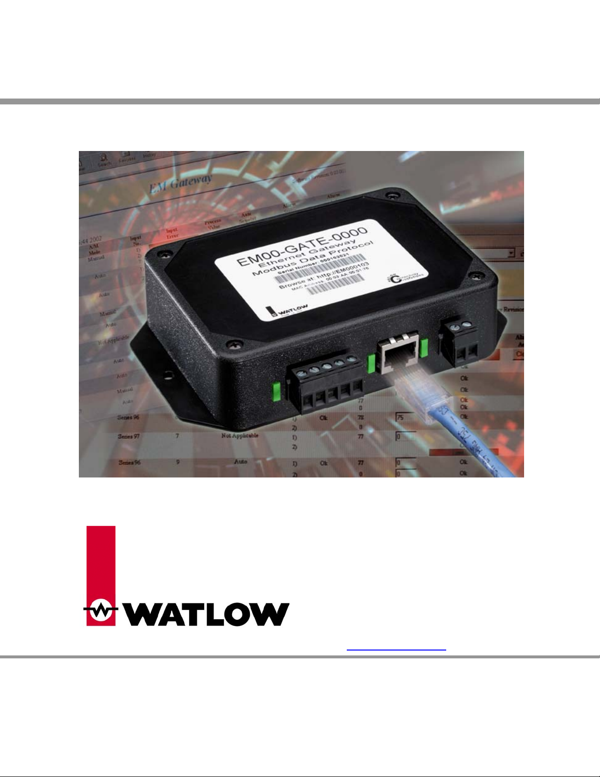
EM Gateway
User’s Manual
For Watlow part number EM00-GATE-0000
1241 Bundy Boulevard, P.O. Box 5580, Winona, Minnesota USA 55987-5580
Phone: +1 (507) 454-5300, Fax: +1 (507) 452-4507, Internet: http://www.watlow.com
0600-0040-0001 Rev D $10.00 February 2004
Page 2

EM Gateway
Table of Contents
Chapter 1: Product Overview 4
Ethernet Gateway 4
Ethernet Gateway Architecture 4
Program Upgrades 5
Chapter 2: Installation and Wiring 6
Dimensions 7
Chapter 3: Configuration 8
Getting Started 8
Network Services 8
Email Alarm Notification 8
Data Logging 9
Control Monitoring and Configuration 9
Chapter 4: HTML Pages 10
EM Gateway 10
EM Gateway Setup 11
EM Gateway Network Setup 12
EM Gateway Email Setup 13
EM Gateway Clock Setup 14
EM Gateway Serial Statistics 15
EM Gateway Network Statistics 16
Chapter 5: Controller Parameters and Registers 17
Series 96 – non-ramping 17
Series 97 17
Series 981 / 982 17
Series 988 / 989 18
Series 998 / 999 18
Series F4S / F4D 18
Series F4P 19
MicroDin 19
Power Series 19
CLS200 Series 20
Series SD – non-ramping 20
2
Page 3

EM Gateway
Table of Contents – cont.
Chapter 6: Reference Documents 25
Reference Documents 25
Serial Numbers 25
Chapter 7: Specifications 26
Power Supply 26
Environmental 26
Indication 26
Agency 26
Communications 26
Control Output Signals 26
Enclosure Size 26
User Interface 26
Ordering Information 26
Declaration of Conformity 27
How to Reach Us 28
3
Page 4

Chapter One
Product Overview
The EM00-GATE-0000 is a gateway / bridge that allows up to 32 Watlow controllers to be directly
connected to an Ethernet network. Using an HTTP Browser such as Microsoft Internet Explorer or
Netscape Navigator you may access 16 controllers and view several controllers’ parameters via an
onboard Web (HTTP) server.
Ethernet Gateway
The Ethernet gateway provides a means for monitoring and configuring runtime parameters of multiple
controllers via a web browser. The gateway is also a bridge for Modbus messages between the Ethernet
bus and EIA-485 or EIA-232 links. The Gateway supports full product configuration; monitoring and
configuration of runtime parameters via MODBUS TCP over TCP/IP using a software package such as
Watview sold by Watlow.
Ethernet Gateway Architecture
This product has three physical connectivity points to the physical world. They are the serial (EIA-485 or
EIA-232), Ethernet port (10BaseT), and the power supply pins.
The EIA-485 / EIA-232 connection supports Modbus RTU protocol and operates as a Master port. It will
initiate data read/write requests to supported standard Watlow controllers. There exists a virtual image of
the controller’s data points in the gateway. The polling engine that initiates the Modbus RTU requests is
responsible for synchronization of the virtual image and the actual controller. Changes to control data
occur both at the controller and at the virtual image.
The 10BaseT connection supports the TCP/IP stack. At the application layer it has an HTTP (web) and
Modbus server. The HTTP server will provide current controller status from the virtual image via HTML.
The HTTP server provides a means of changing some runtime parameters via HTML. The TCP/IP stack
supports DHCP client, AutoIP, static IP, DNS client, and Netbios name resolution. The 10BaseT
connector is an RJ45 per the IEEE 802.3 specification.
The EM00-GATE-0000 can be used as a bridge for Modbus RTU messages. This is concurrent with all
other communicating functions. In this scenario, the gateway simply passes the request that comes in on
the Ethernet connection through to the EIA-485 or EIA-232 connection. When the response is returned
from the controller, it is sent back on the Ethernet connection. No processing of the packet contents is
necessary to bridge the two physical layers.
Block Diagram of Gateway
PowerSource
RS-485
EtherNet
TCP/IP
Modbus
TCP/IP
TFTP
Client
WEB
Server
GATEWAY
Virtual
Image
Modbus
RTU
Poll
Engine
4
Page 5

Program Upgrades
The gateway has a TFTP server for the purposes of reprogramming the program memory. A program
update will be initiated when a TFTP client, residing on a PC, begins to write a new program file to the
gateway TFTP server. When reprogramming the program memory, all other gateway services are
unavailable.
The gateway provides no means of updating the program memory of controller devices, such as flashing
new information into the Series F4.
5
Page 6
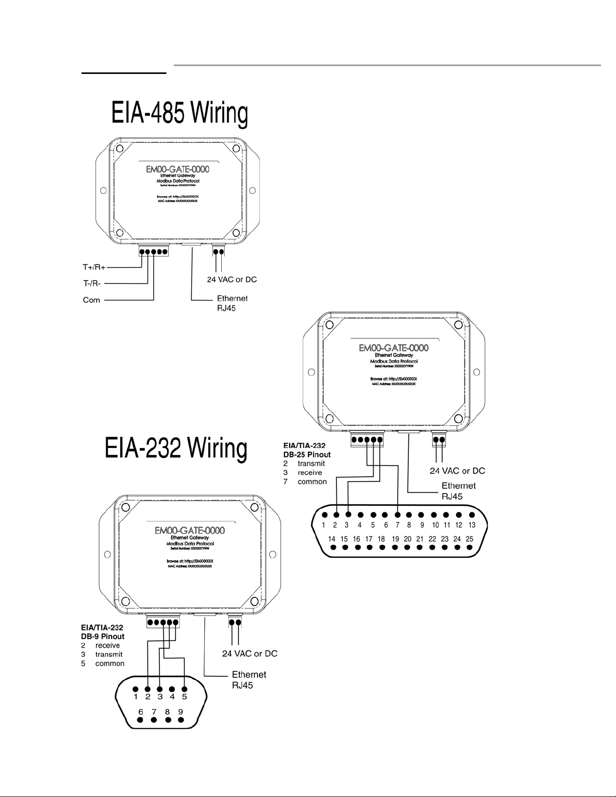
Chapter Two
Installation & Wiring
UL Approved, Class 2 power supply
required
6
Page 7
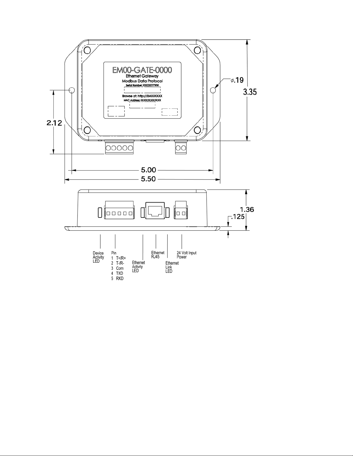
Dimensions are in inches
7
Page 8

Chapter Three
Configuration
Getting Started
Perform these steps;
1. Connect the EM00-GATE-0000 gateway to your computer’s Ethernet port using a cross-wired RJ45
cable or connect the EM00-GATE-0000 to a hub or network using a straight wired RJ45 Category 5
cable. The EM00-GATE-0000 is limited to a 10BaseT connection and will not work on an Ethernet
port set for 100BaseT only. Use of a 10/100 hub will overcome this issue if your PC has only a
100BaseT port.
2. Wire the temperature controllers to the gateway’s EIA-485 port. You may connect the gateway’s EIA232 port to a controller if you will be using only one controller, provided that the controller has an EIA232 port.
3. Wire a 24-volt AC or DC power supply to the gateway terminals. This is not polarity sensitive.
4. Configure each controller to the same baud rate (9600 or 19200) from the front panel of the
controller. Set each controller’s Modbus address to a unique number. As an example, set the first
controller to address 1, the second to address 2 and so on.
5. Power up the gateway, controllers and PC.
6. Start your Internet browser. Enter the TCP/IP address of the gateway into the browsers’ address field.
Two different addresses may be used to access the gateway. Either EMxxxxxx, where xxxxxx is the
first six digits of the serial number, or WATxxxxxx, where xxxxxx is the last six digits of the gateways’
MAC address. The MAC address is printed on a decal in the form xx:xx:xx:xx:xx:xx.
7. Select the Gateway Setup Page. Enter User name ‘new’ and Password ‘user’ by default. The
Password can be changed on the Security Configuration screen.
8. Configure the Baud Rate and range of controllers’ addresses to match those you configured in step
four.
9. Click on Rescan Modbus Network
10. Click on the back button of the browser to return to the previous page.
11. Click on the refresh button of the browser and your controllers’ information should now be visible.
Note: You must click on the refresh button within the browser to capture the latest controller information.
This information is automatically refreshed after 10 seconds by default. You may change this refresh time
using the appropriate page.
Network Services
The EM00-GATE-0000 supports DHCP client, autoIP, and static IP for address assignment. Normally you
will not need to make any changes. The user is able to configure preferences as to which services are
used if available. Intelligence is employed within the gateway to revert to backup IP assignment methods
if the primary method is unavailable.
The gateway does support DNS client and Netbios name resolution. Configuration information may be
entered at the EM Gateway Network Display Setup page.
Email Alarm Notification
The email function allows the user to send emails to four addresses alerting them of alarm conditions that
have occurred on the controllers connected to the Gateway. A button on the Graphical User Interface
(GUI) allows the user to enable or disable this feature. Emails can be generated whenever an alarm
condition occurs for each controller. An email acknowledge feature requires that the user acknowledge
the email message by operating the email acknowledge button before additional email alarm messages
can be generated for that controller. For multiloop controllers only one email acknowledge feature is
supported; if more than one loop produces an alarm, only the first alarm detected will generate an email
until acknowledged.
8
Page 9

You will need to configure your Gateway with your SMTP server name or address. A DNS server address
must also be configured if using a SMTP name. Contact your system administrator if you don’t know the
SMTP name or address.
Data Logging
The gateway provides no explicit means of data logging. Data can be polled via Modbus TCP by an
external PC program. Consider WatView from Watlow for your setup, data logging and graphing needs.
Control Monitoring and Configuration
The gateway provides a means of monitoring the current process value for analog inputs of each
controller using a built-in HTTP server. It also provides a means of monitoring the present alarm status of
each controller. Additionally, you may monitor and change control set points for control loops of each
controller.
The gateway is capable of supporting Watlow Series 96 non-ramping, 97, 981, 982, 988, 989, 998, 999,
F4S, F4D, F4P, MicroDin, Power Series, CLS200and SD non-ramping controllers with up to 16
controllers in any combination.
The gateway is capable of automatically determining when a controller is connected to the serial bus. It
will identify the model and address of each controller. Controllers with duplicate Modbus addresses will
be ignored by the gateway.
You can configure the baud rate of the EIA-485 or EIA-232 bus. You may also specify which controller
addresses are scanned under the EM Gateway Setup page. The gateway supports from 1 to 16
controllers in any combination of supported model numbers. Select Rescan Modbus Network to update
the detection of controllers on the bus. The Modbus network is automatically scanned every two minutes
for new devices.
9
Page 10
Chapter Four
HTML Pages
The section describes the pages available from the EM Gateway’s Web server.
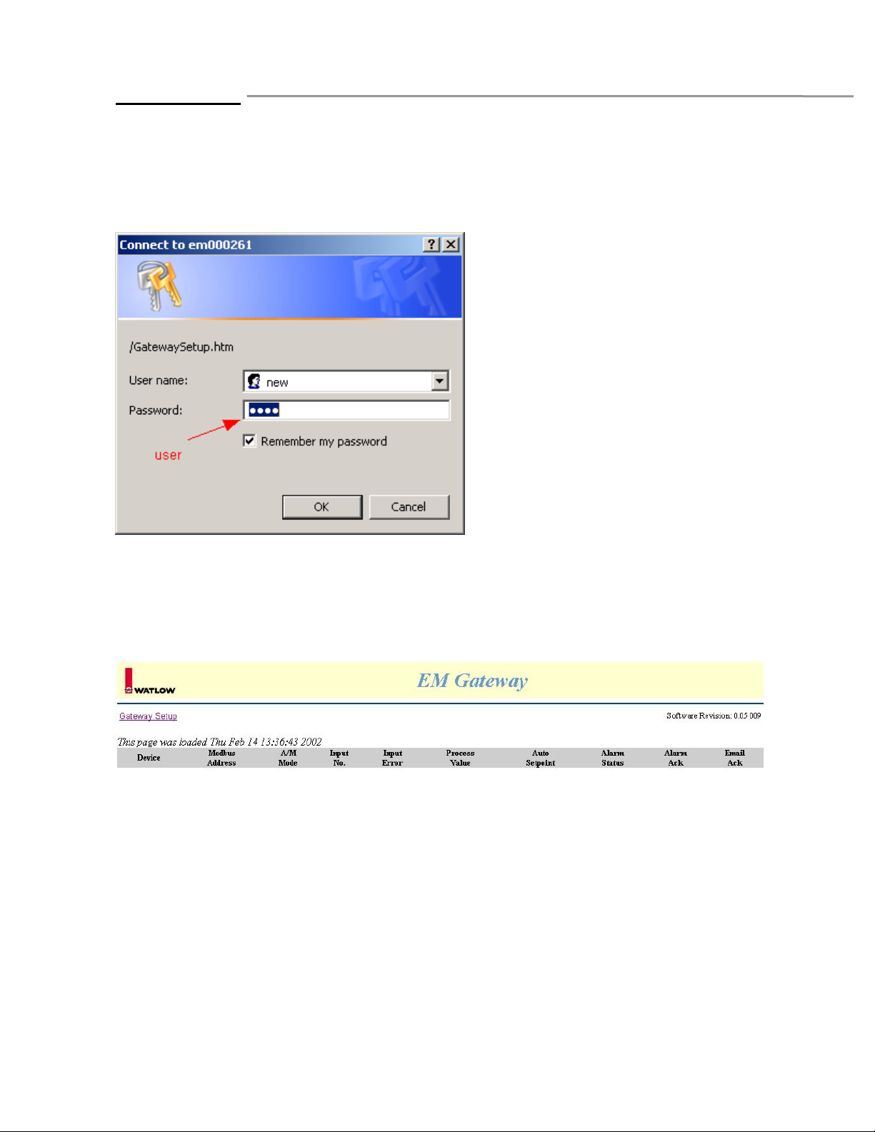
When the web page is first accessed, you are prompted for a User name and Password. The default User
name is ‘new’. The default Password is ‘user’. These are case sensitive. The user name and password
may be changed on the security configuration page.
F4 1 Auto 1) Ok 100 120 Alarm 1 Ok
2) Ok 135 136
Series 982 2 Hold 1) Ok 78 78 Alarm 2 Ok
2) Ok Alarm 3 Ok
This is the main page for monitoring the controllers on the Gateway. You can click on values that are located
within a box. Entering in a new value may change these values. In addition, use Alarm Ack to clear alarms when a
process value has returned within a safe operating range. Use the Email Ack to reactivate future emails for this
controller. See the controller’s user’s manuals for details of Modes, Errors, and Alarm operation.
10
Page 11
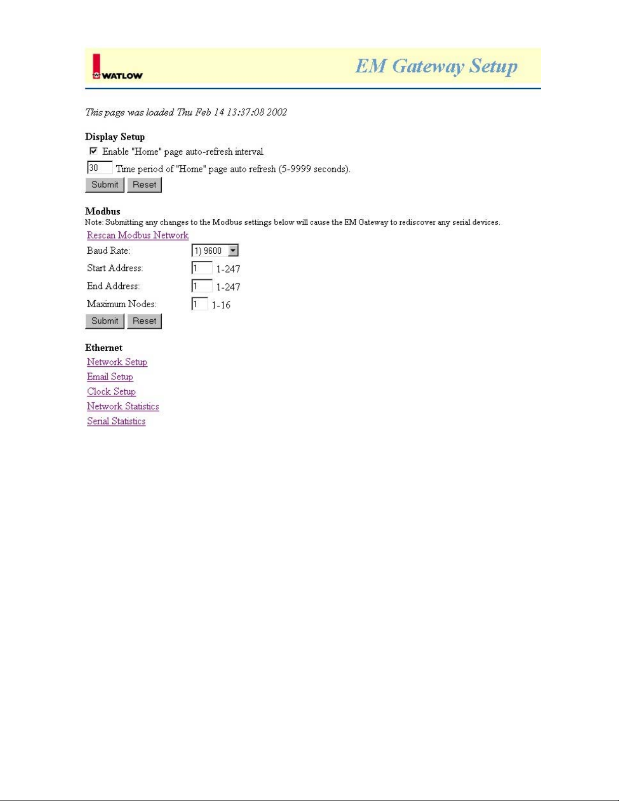
Use this page to disable or enable automatic page refreshing or to change the time in between
refreshes.
In addition, you can force a rescan of the Modbus Network. This will cause the Gateway to detect any
new devices added to the serial network. Set the baud rate of the network to 9600 or 19200-baud. The
value selected must match the value in all of the controllers on the serial network. Up to 16 controllers
may be scanned by the Gateway using the built-in HTTP server. Set a start address to the lowest
address number of the controller on the serial network. Set an end address to the highest address
number of the controller on the serial network.
As an example, you have your first controller set to address 23 and the last one set to 35. Set Start
Address to 23 and End Address to 35. You can limit the number of controllers accessed by the
Gateway by setting the Maximum Nodes value to less than 16.
Lastly, this page provides links to Network Setup, Email Setup, Clock Setup, Network Statistics, and
the Serial Statistics pages.
11
Page 12

Use this page to change the Gateway identification name or to change the IP Address Resolution
Method. Contact your IS administrator for questions regarding these settings.
12
Page 13
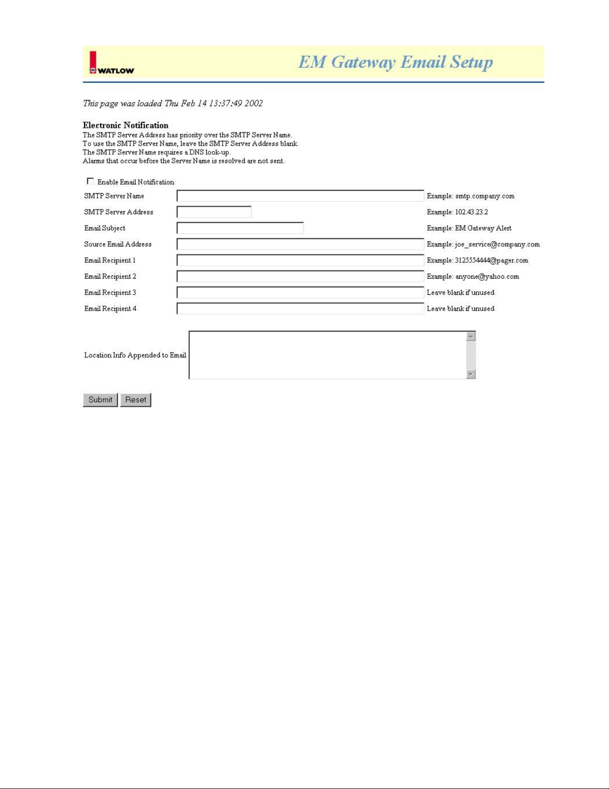
Use this page to enable notification and configure the addresses for email recipients. These recipients
will receive an email when an alarm occurs on any controller. Contact your IS administrator for
questions regarding these settings.
13
Page 14
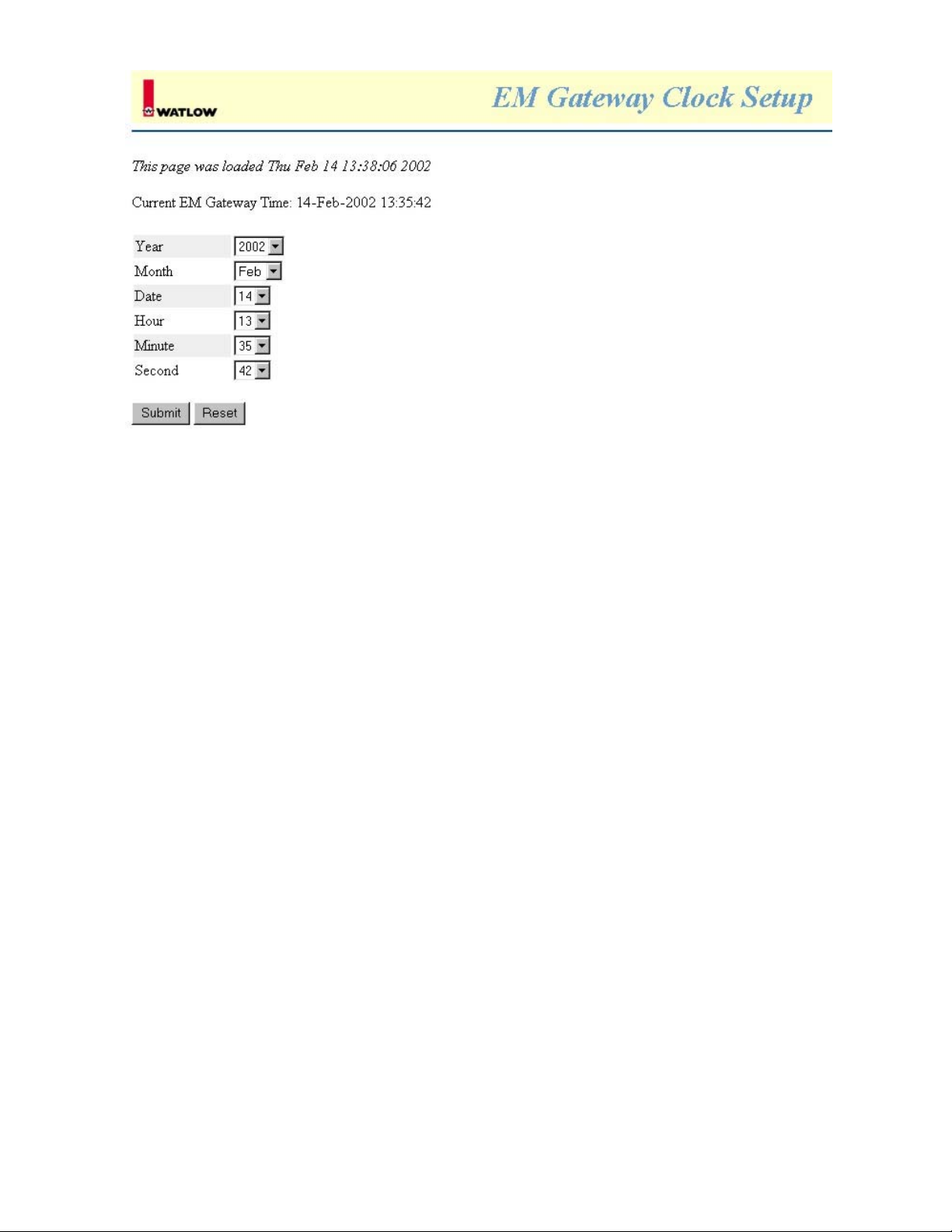
Use this page to update the time and date stored in the Gateway. This information is used to identify
the time and date of alarms when emails are sent.
14
Page 15

1 0 0 0 0 1174 0
2 0 0 0 0 1174 0
3 0 0 0 0 1174 0
4 0 0 0 0 1174 0
5 0 0 0 0 1174 0
6 0 0 0 0 1174 0
7 0 0 0 0 1174 0
8 0 0 0 0 1174 0
9 0 0 0 0 1174 0
10 0 0 0 0 1174 0
11 5 2 0 3 1167 0
12 0 0 0 0 1174 0
13 0 0 0 0 1174 0
14 0 0 0 0 1174 0
15 0 0 0 0 1174 0
16 0 0 0 0 1174 0
The Serial Statistic page is used to monitor the health of the controller network. These numbers will
help identify when there are issues with wiring, duplicate Modbus ID addresses or noise on
communication wires on the controller side of the network. In this example, controller number 11 is
experiencing failure in communication quality.
Timeout Errors increments anytime that a controller does not respond in an appropriate amount of
time.
Retry Errors increments anytime that a controller does not respond after 3 attempts to read
information.
CRC Errors increments anytime that the controller responds with a bad packet.
Bad Polls increments when there are timeouts and the retries did not successfully retrieve information.
Good Polls increments on each valid packet received.
Illness increments anytime that there are 5 CRC or Timeout errors in a row. After a count of 5 in the
Illness column, the controller is flagged as having no communication. On the next valid packet
received, the Illness value is cleared to zero and communications is restored.
You must refresh the browser to see these numbers update.
15
Page 16

This page was loaded Wed Feb 1318: 00:28 2002
IP Address 7.3.37.91
Subnet 255.255.224.0
Gateway 7.3.63.250
Mac Address 00:03:AA:00:00:C1
Receives 128349
Unicasts 1207
Multicasts 0
Broadcasts 127061
Rx Errors 0
Rx Missed 2089
Rx CRC Errors 28
Rx Drops 0
Transmits 1251
Buffer Defers 0
Tx Errors 0
Tx Collisions 0
Tx Coll. Overflow 0
Tx FILO Errors 0
Traffic Backoffs 0
Network Rejects 84154
Address Rejects 25
Protocol Rejects 10492
ARP Rejects 19361
SMTP Server IP 0.0.0.0
Send Queue Length 0
Send Queue Max 1
Send Queue Min 0
Recv Queue Length 0
Recv Queue Max 7
Recv Queue Min 0
Big Queue Length 28
Big Queue Max 30
Big Queue Min 26
Little Queue Length 28
Little Queue Max 30
Little Queue Min 2
The Network Statistics page monitors the health of the Ethernet network. These numbers will help identify
settings for the EM Gateway as well as when there are issues with wiring, incorrect addresses or noise
on communication wires on the Ethernet side of the Gateway.
16
Page 17

Chapter Five
Controller Parameters and Registers
The EM Gateway supports the following parameters for each type of controller when using an HTTP
browser:
Series 96 – non-ramping
Operation Mode – register 200 with choice of Auto or Manual as read only
Input Error – register 101 with choice of Sensor Error or Ok as read only
Process Value Input 1 – register 100 as read only
Process Value Input 2 – register 105 as read only
Auto Set Point 1 – register 300 as read/write
Alarm Status Output 2 – register 106 with choice of Ok, Alarm High, Alarm Low, Alarm High Latched,
Alarm Low Latched, Alarm High Silenced, Alarm Low Silenced, Alarm High Latched Silenced, Alarm
Low Latched Silenced, Waiting for in Range Alarm, Alarm Disabled, or Alarm Error as read only
Alarm Status Output 3 – register 106 with choice of Ok, Alarm High, Alarm Low, Alarm High Latched,
Alarm Low Latched, Alarm High Silenced, Alarm Low Silenced, Alarm High Latched Silenced, Alarm
Low Latched Silenced, Waiting for in Range Alarm, Alarm Disabled, or Alarm Error as read only
Alarm Acknowledge – register 331 with choice to clear alarm as write only
Note: Selecting Manual control using the Operation Mode, an input error or inputting a Set Point value
less than –30000 will disable the Auto Set Point. Alarms not configured are not displayed. Alarms can not
be acknowledged while the alarm condition exists.
Series 97
Process Value Input 1 – register 100 as read only
Limit Status – register 319 with choice of Ok, High Limit, Low Limit, or Limit Error as read only
Alarm Status Output 2 – register 106 with choice of Ok, Alarm High, Alarm Low or Alarm Error as read
only
Alarm Status Output 3 – register 110 with choice of Ok, Alarm High, Alarm Low, or Alarm Error as read
only
Alarm Acknowledge – register 331 with choice to clear alarm as write only
Note: Alarms configured are displayed. Alarms can not be acknowledged while the alarm condition exists.
Series 981 / 982
Operation Mode – register 200 with choice of Hold, Run, or Pre-run as read only
Input Error – register 209 with choice of Sensor Error or Ok as read only
Process Value Input 1 – register 100 as read only
Auto Set Point – register 300 as read/write
Alarm Status Output 2 – register 106 with choice of Ok, Alarm High, Alarm Low or Alarm Error as read
only
Alarm Status Output 3 – register 110 with choice of Ok, Alarm High, Alarm Low, or Alarm Error as read
only
Alarm Acknowledge – register 106 with choice to clear alarm as write only
Note: An input error or inputting Set Point values less than –30000 will disable the Auto Set Point. Alarms
not configured are not displayed. Alarms can not be acknowledged while the alarm condition exists.
17
Page 18

Series 988 / 989
Operation Mode – register 10 with choice of Auto or Manual as read only
Input Error – register 4 with choice of Sensor Error or Ok as read only
Process Value Input 1 – register 1 as read only
Process Value Input 2 – register 2 as read only
Auto Set Point – register 7 as read/write
Alarm Status Output 2/3 – register 3 with choice of Ok, Alarm High, Alarm Low or Alarm Error as read
only
Alarm Acknowledge – register 3 with choice to clear alarm as write only
Note: Selecting Manual control using the Operation Mode, an input error or inputting Set Point values less
than –30000 will disable the Auto Set Point. Alarms not configured are not displayed. Alarms can not be
acknowledged while the alarm condition exists.
Series 998 / 999
Operation Mode – register 301 with choice of Auto or Manual as read only
Input Error – register 209 with choice of Sensor Error or Ok as read only
Process Value Input 1 – register 100 as read only
Process Value Input 2 – register 104 as read only
Auto Set Point 1 – register 300 as read/write
Auto Set Point 2 – register 319 as read/write
Alarm Status Output 3 – register 110 with choice of Ok, Alarm High, Alarm Low, or Alarm Error as read
only
Alarm Acknowledge – register 110 with choice to clear alarm as write only
Note: Selecting Manual control using the Operation Mode, an input error or inputting Set Point values less
than –30000 will disable Auto Set Points 1 or 2. Alarms not configured are not displayed. Alarms can not
be acknowledged while the alarm condition exists.
Series F4S / F4D
Operation Mode – register 200 with choice of Auto or Manual as read only
Input 1 Error – register 101 with choice of Sensor Error or Ok as read only
Input 2 Error – register 105 with choice of Sensor Error or Ok as read only
Input 3 Error – register 109 with choice of Sensor Error or Ok as read only
Process Value Input 1 – register 100 as read only
Process Value Input 2 – register 104 as read only
Process Value Input 3 – register 108 as read only
Auto Set Point 1 – register 300 as read/write
Auto Set Point 2 – register 319 as read/write
Alarm Status Output 2 – register 102 with choice of Ok, Alarm High, Alarm Low, Alarm High Latched,
Alarm Low Latched, Alarm High Silenced, Alarm Low Silenced, Alarm High Latched Silenced, Alarm
Low Latched Silenced, Waiting for in Range Alarm, Alarm Disabled, or Alarm Error as read only
Alarm Status Output 3 – register 106 with choice of Ok, Alarm High, Alarm Low, Alarm High Latched,
Alarm Low Latched, Alarm High Silenced, Alarm Low Silenced, Alarm High Latched Silenced, Alarm
Low Latched Silenced, Waiting for in Range Alarm, Alarm Disabled, or Alarm Error as read only
Alarm 1 Acknowledge – register 312 with choice to clear alarm as write only
Alarm 2 Acknowledge – register 331 with choice to clear alarm as write only
Note: Alarms configured are displayed. Alarms can not be acknowledged when the alarm condition still
exists.
18
Page 19

Series F4P
Operation Mode – register 200 with choice of Auto or Manual as read only
Input 1 Error – register 101 with choice of Sensor Error or Ok as read only
Input 2 Error – register 105 with choice of Sensor Error or Ok as read only
Input 3 Error – register 109 with choice of Sensor Error or Ok as read only
Process Value Input 1 – register 100 as read only
Process Value Input 2 – register 104 as read only
Process Value Input 3 – register 108 as read only
Auto Set Point – register 300 as read/write
Alarm Status Output 2 – register 102 with choice of Ok, Alarm High, Alarm Low, Alarm High Latched,
Alarm Low Latched, Alarm High Silenced, Alarm Low Silenced, Alarm High Latched Silenced, Alarm
Low Latched Silenced, Waiting for in Range Alarm, Alarm Disabled, or Alarm Error as read only
Alarm Status Output 3 – register 106 with choice of Ok, Alarm High, Alarm Low, Alarm High Latched,
Alarm Low Latched, Alarm High Silenced, Alarm Low Silenced, Alarm High Latched Silenced, Alarm
Low Latched Silenced, Waiting for in Range Alarm, Alarm Disabled, or Alarm Error as read only
Alarm 1 Acknowledge – register 312 with choice to clear alarm as write only
Alarm 2 Acknowledge – register 331 with choice to clear alarm as write only
Note: Alarms configured are displayed. Alarms can not be acknowledged when the alarm condition still
exists.
MicroDIN
Operation Mode – register 200 with choice of Auto or Manual as read only
Input Error – register 101 with choice of Sensor Error or Ok as read only
Process Value Input 1 – register 100 as read only
Auto Set Point – register 300 as read/write
Alarm Status Output 2 – register 106 with choice of Ok, Alarm High, Alarm Low, Alarm High Latched,
Alarm Low Latched, Alarm High Silenced, Alarm Low Silenced, Alarm High Latched Silenced, Alarm
Low Latched Silenced, Waiting for in Range Alarm, Alarm Disabled, or Alarm Error as read only
Alarm Acknowledge – register 331 with choice to clear alarm as write only
Note: Alarms configured are displayed. Alarms can not be acknowledged when the alarm condition still
exists.
Power Series
Heat Sink Temperature in Degrees C - register 1590 as read only
Load Current in Amps RMS on Line 1 - register 154 as read only (Based on configuration)
Load Current in Amps RMS on Line 2 - register 164 as read only (Based on configuration)
Load Current in Amps RMS on Line 3 - register 174 as read only (Based on configuration)
Note: Display of current on lines 1, 2, and 3 depends on the number of zones, the installed options and
the load type.
19
Page 20
CLS200 Series (Loop 1 to 16 if available)
Operation Mode – register 264 to 279 with choice of Auto or Manual as read only
Input Error – registers 660 to 675 with choice of Ok, TC Reversed, TC Short, TC Open, RTD Open, or
RTD Short as read only
Process Value – registers 363 to 378 as read only
Auto Set Point – registers 330 to 345 as read/write
Alarm Status – registers 660 to 675 with choice of Ok, Low Deviation, High Deviation, Low Process, or
High Process as read only
Alarm Acknowledge – registers 8311 to 8326 with choice to clear alarm as write only
Note: Alarms configured are displayed. Alarms can not be acknowledged when the alarm condition still
exists.
Note: The Communication Specifications manual list absolute registers, which are the relative register
with 40001 added to them. As an example, relative register 264 is absolute register 40265.
Series SD – non-ramping
Operation Mode – register 25 with choice of Auto or Manual as read only
Input Error – registers 24 with choice of Ok or Error as read only
Process Value – registers 20, 21 as read only
Auto Set Point – registers 27, 28 as read/write
Alarm 1 Status – registers 29 and 30 of Alarm 1 Ok, Alarm 1 Low Alarm, or Alarm 1 High Alarm as read
only
Alarm 2 Status – always OK as this is the same output as communications.
Alarm 3 Status – registers 33 and 34 of Alarm 3 Ok, Alarm 3 Low Alarm, or Alarm 3 High Alarm as read
only
Note: Alarms configured are displayed. Alarms can not be acknowledged when the alarm condition still
exists.
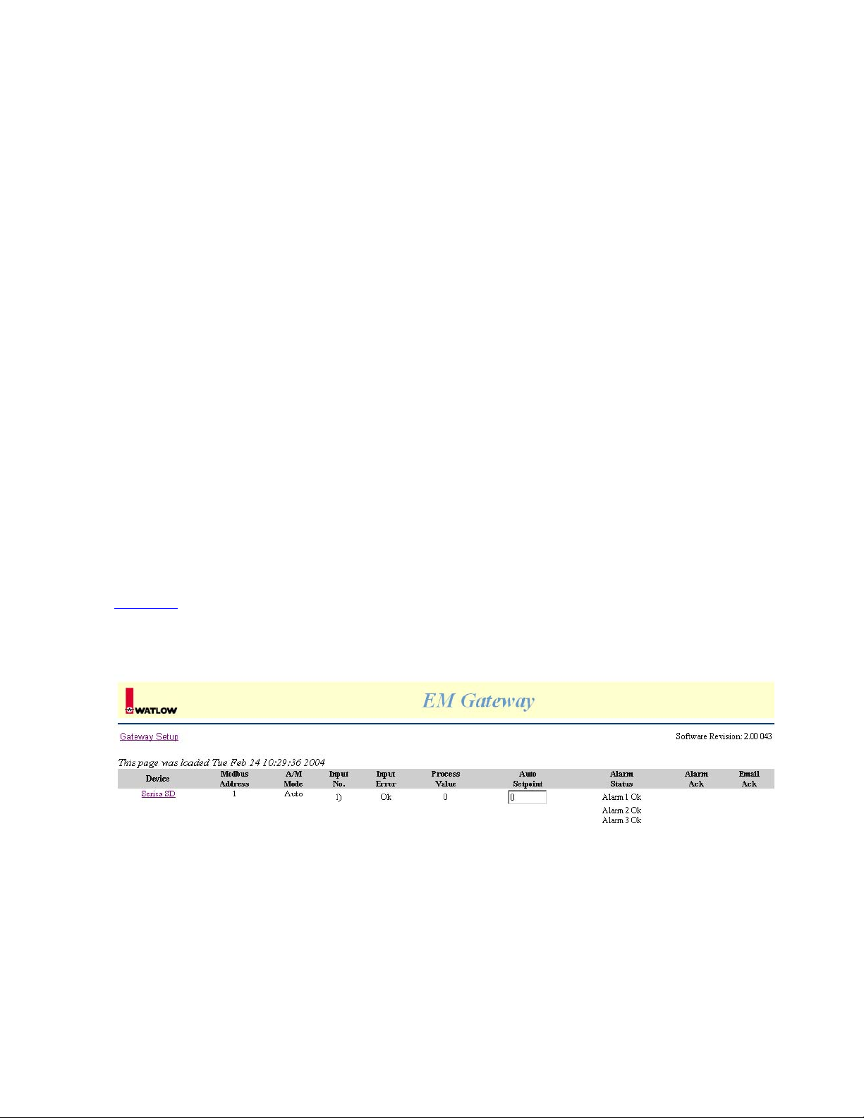
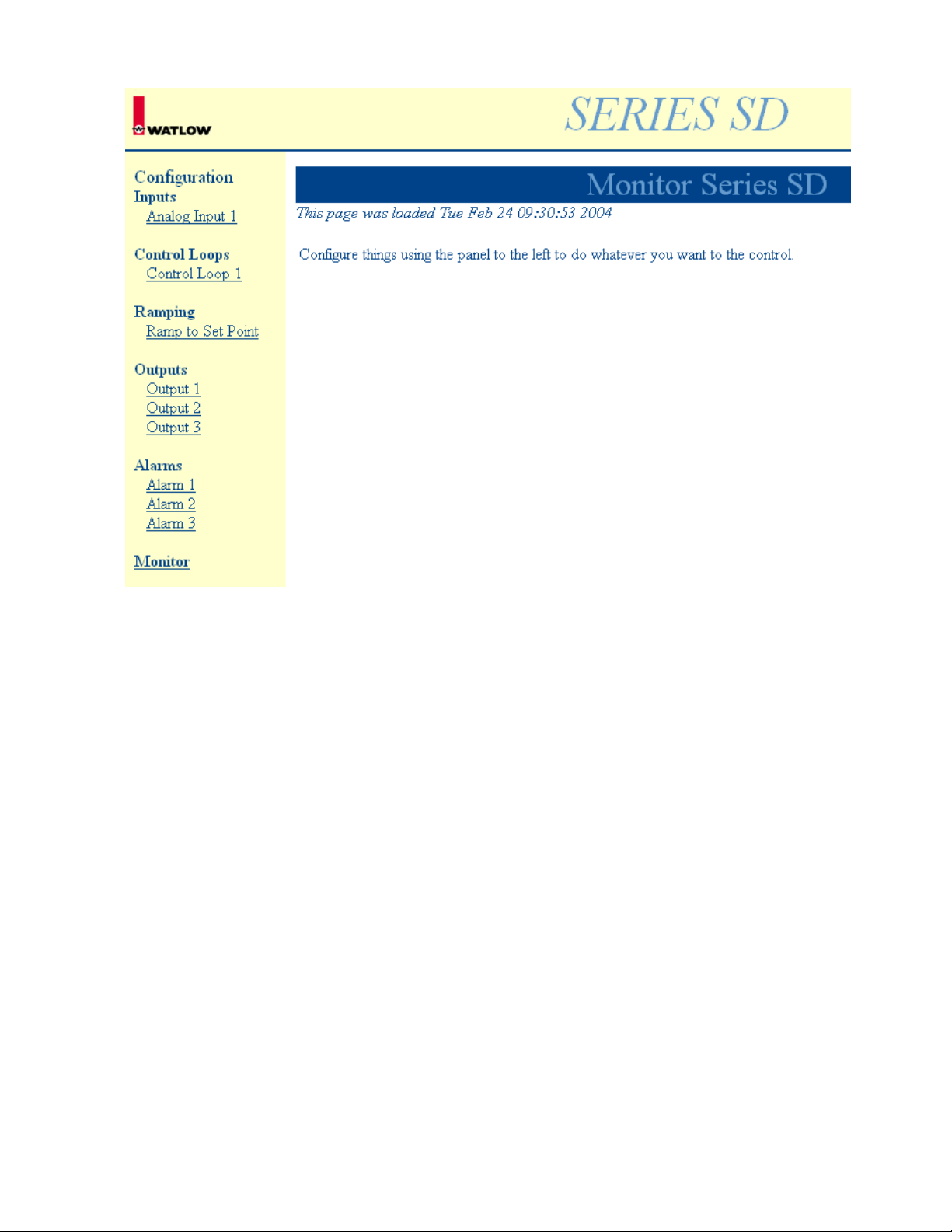
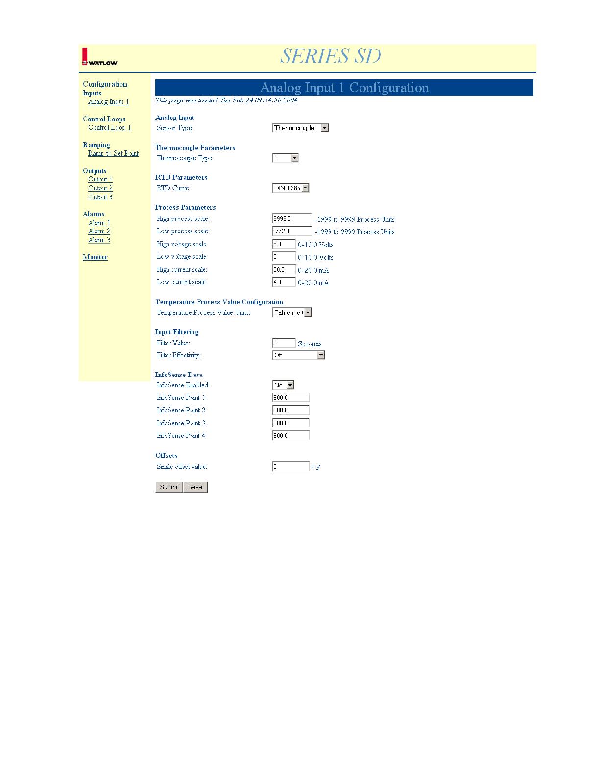
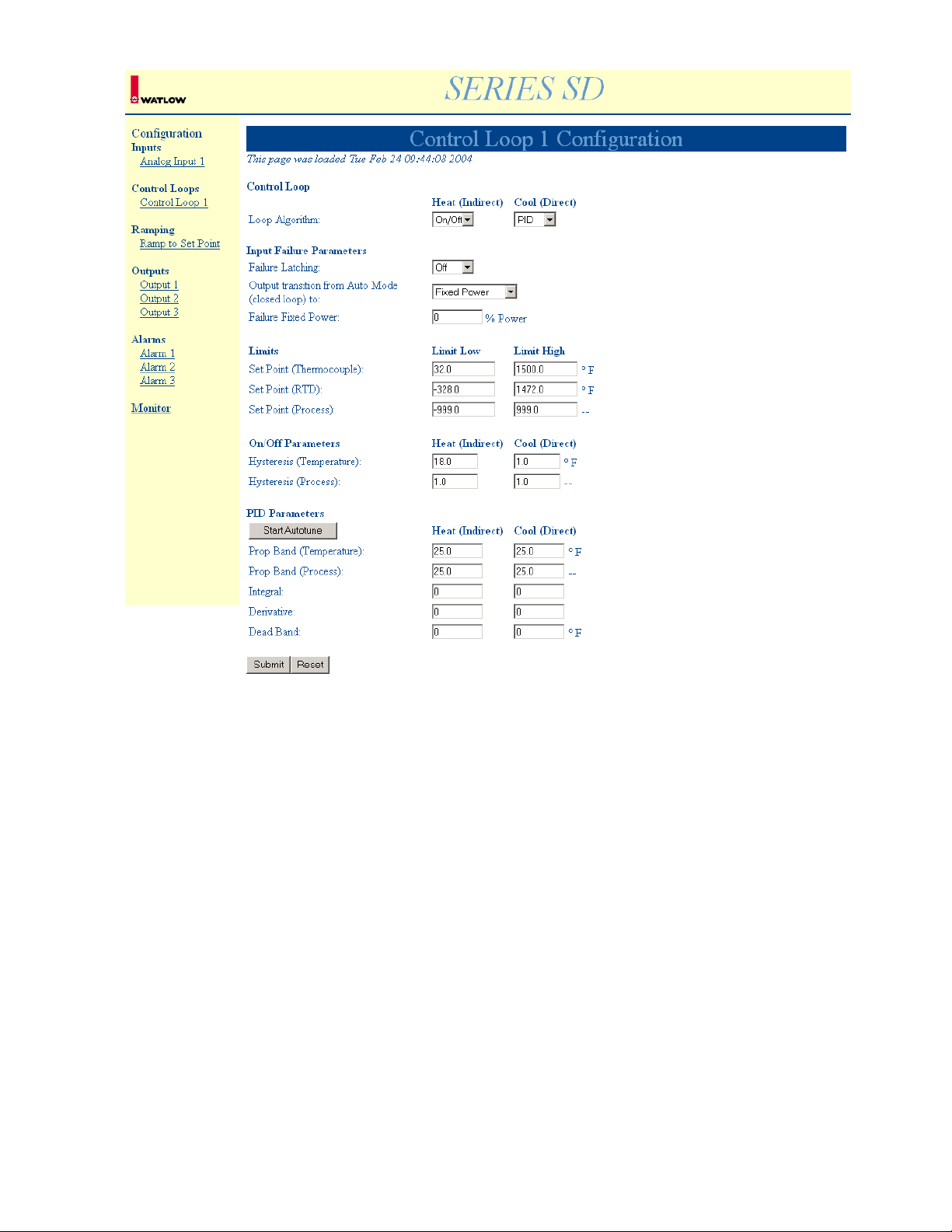
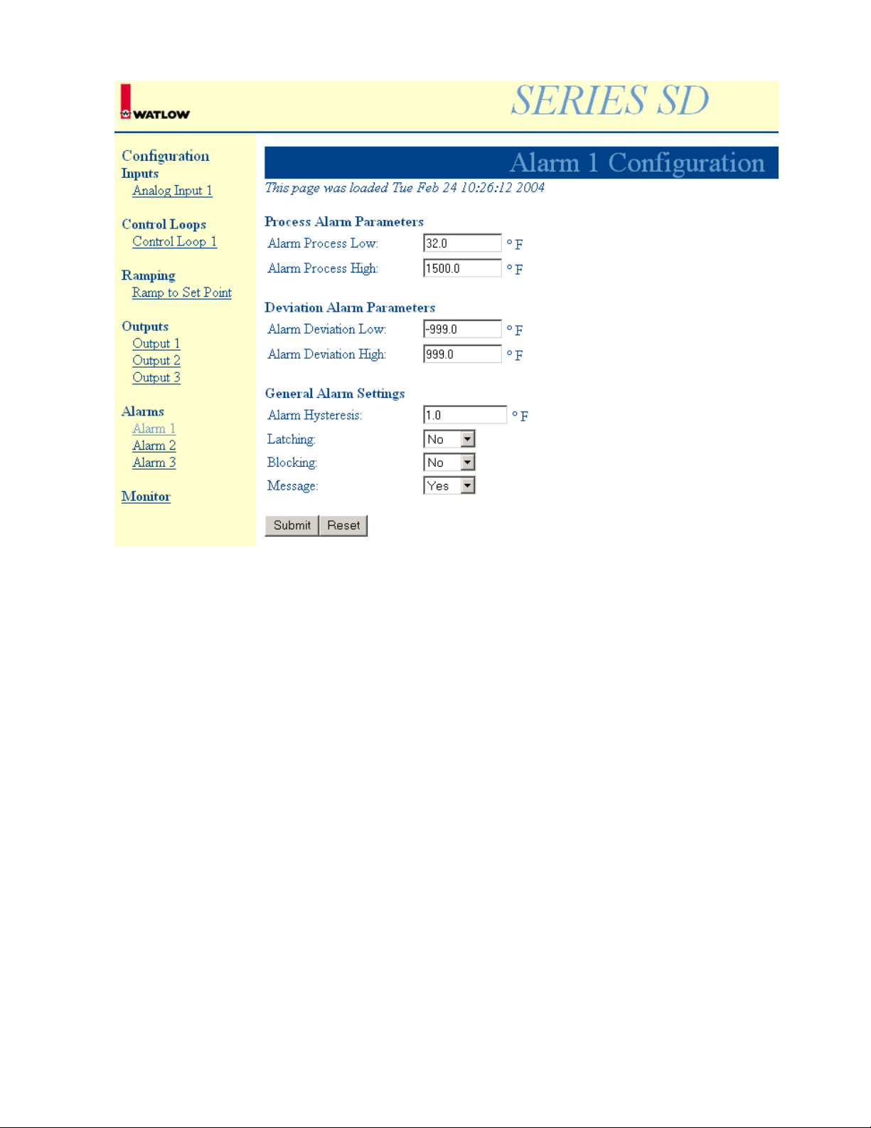
In addition, the Series SD has many other parameters to read or change by clicking on the link
SeriesSD. Be sure to submit any changes made on these screens using the Submit button at the bottom
of the screen.
The following are screen captures from the Series SD:
20
Page 21
2122232425
Page 22
Page 23
Page 24
Page 25

Chapter Six
Reference Documents
The MODBUS RTU specification is located at: http://www.modicon.com/techpubs/toc7.html or
http://www.modbus.org
Serial Numbers
Gateways are labeled with a unique serial number in numeric and bar code formats. The serial number is
embedded in the gateway firmware.
EM Gateway Features and Benefits
• Ethernet/Internet connectivity
Operate & monitor your process remotely.
• Browser Graphical User Interface (GUI)
Operate & monitor your process remotely with standard Web browsers.
• Dedicated Web page design
Easy to understand and operate
• Email alarm notification
Reduced process monitoring costs
Page 26

Chapter Seven
Specifications
Power supply
• Voltage input 24 V (ac/dc) +10%, -15% 50/60 Hz +/- 5
• Connection through 2-position removable screw style terminal block
• 22 to 12 AWG
• Power consumption 10 VA MAX
• UL Approved, Class 2 power supply required
• Real-time Clock backed by 3v-lithium battery – RAYOVAC BR1225
Environmental
• Operating temperature range: 0 to 60°C
• Storage temperature range: -40 to 70°C
• Operating and storage humidity: 0 to 90% non-condensing
Indication
• Green LED for Ethernet connection
• Green LED for Ethernet activity
• Green LED for EIA-485 or EIA-232 activity
Agency
• CE Approved, see Declaration of Conformity 61326 Industrial Immunity, Class B Emissions
Communications
• MODBUS RTU communications
• Both EIA-485 and EIA-232 supported at 9600 and 19200 baud
• Connection through 5-position removable screw style terminal block
• 22 to 12 AWG
• Ethernet communications
• Ethernet RJ45 Connector
• 10BaseT per IEEE 802.3 Ethernet Standard
• HTTP v1.1
• Modbus TCP
• DHCP, Auto IP, Or Fixed IP Address
• Email Alarm Notification
• Supports Windows browsers
• Microsoft Internet Explorer 4.0 or newer
• Netscape 4.0 or newer
Control Output Signals
Activity L.E.D. for Ethernet communications per IEEE 802.3
Activity L.E.D. for Serial communications.
Enclosure Size
Dimensional Size - L: 3.75 in X W: 1 in X H: 2.5 in, with cutouts for L.E.D.s, RJ45 port and power jack.
User Interface
3 L.E.D.s to indicate operation status; Ethernet link, Ethernet traffic and Modbus traffic.
Ordering Information
Order part number EM00-GATE-0000
26
Page 27

Declaration of Conformity
Gateway Products
Watlow Winona, Inc.
1241 Bundy Blvd.
Winona, MN 55987 USA
Declares that the following product:
Model Numbers: EM00-GATE-0000, NGW0-0000-2400 and NGW0-0000-0000*
Classification: Communications interface card, Installation Category I, Pollution
degree II
Rated Voltage: 24V (ac or dc) or 5V (dc)
Rated Frequency: 50/60 Hz or dc
Rated Power: 10VA maximum
*NGW0-0000-0000 Requires use of a Ferrico NF130 Clamp on ferrite on all lines to pass Class B
emissions. Depending on end use setup, this bead may or may not be necessary.
Meets the essential requirements of the following European Union Directives by using the relevant
standards show below to indicate compliance.
89/336/EEC Electromagnetic Compatibility Directive
EN 61326:1997 With A1:1998 – Electrical equipment for measurement, control and
laboratory use – EMC requirements (Industrial Immunity, Class B Emissions).
EN 61000-4-2:1996 With A1, 1998 – Electrostatic Discharge Immunity
EN 61000-4-3:1997 – Radiated Field Immunity
EN 61000-4-4:1995 – Electrical Fast-Transient / Burst Immunity
EN 61000-4-5:1995 With A1, 1996 – Surge Immunity
EN 61000-4-6:1996 – Conducted Immunity
EN 61000-4-11:1994 Voltage Dips, Short Interruptions and Voltage Variations Immunity
EN 61000-3-2:1995 With A1-3:1999 – Harmonic Current Emissions
EN 61000-3-3:1995 With A1:1998 – Voltage Fluctuations and Flicker
Use of an appropriately approved class 2 power source is required for compliance.
Jim Boigenzahn Winona, Minnesota, USA
Name of Authorized Representative Place of Issue
General Manager February 28, 2002
Title of Authorized Representative Date of Issue
Signature of Authorized Representative
27
Page 28

How to Reach Us
Technical Assistance
If you encounter a problem with your EM Gateway, review all of your wiring and configuration information
to verify that your selections are consistent with your application. If the problem persists after checking
the above, you can get technical assistance from your local Watlow representative, or by dialing (507)
454-5300. An applications engineer will discuss your application with you.
Warranty
This product is warranted free from defects in material and workmanship for 36 months after delivery to
the first purchaser for use, providing that the units have not been misapplied. Since Watlow has no
control over their use, and sometimes misuse, we cannot guarantee against failure. Watlow’s obligations
hereunder, at Watlow’s option, are limited to replacement, repair or refund of purchase price, and parts
that upon examination prove to be defective within the warranty period specified. This warranty does not
apply to damage resulting from transportation, alteration, misuse or abuse.
Returns
• Call or fax Customer Service for a Return Material Authorization (RMA) number before returning any
product.
• Put the RMA number on the shipping label, and provide a written description of the problem.
• A restocking charge of 20% of the net price is charged for all standard units returned to stock.
Your Feedback
Your comments or suggestions on this manual are welcome, please send them to: Technical Writer,
Watlow Winona, 1241 Bundy Blvd., P.O. Box 5580, Winona, MN 55987-5580, Phone: (507) 454-5300,
Fax: (507) 452-4507. Watlow Winona, Inc., ©, copyrights the EM User’s Manual February 2002, with all
rights reserved. (2206)
28
 Loading...