

Watlow DA1V-1660-F000, DA10-02F0-0000, DA10-60K2-0000, DA10-24K3-0000, DA10-02K2-0000 User manual
...
The DIN-A-MITE is warranted to be free of defects in material
and workmanship for 36 months after delivery to the first
purchaser for use, providing that the units have not been
misapplied. Since Watlow has no control over their use, and
sometimes misuse, we cannot guarantee against failure. Watlow’s
obligations hereunder, at Watlow’s option, are limited to
replacement, repair, or refund of purchase price, and parts which
upon examination prove to be defective within the warranty
period specified. This warranty does not apply to damage
resulting from transportation, alteration, misuse, abuse, or
improper fusing.
Warranty
The DIN-A-MITE Style A User’s Manual is copyrighted by
Watlow, Inc., © January 2016, with all rights reserved.
DIN-A-MITE
®
Style A
Solid-State Power Controller
User’s Manual
Please consult this user manual when you place your new
DIN-A-MITE in service. It contains all the necessary
information to mount and wire the product into the
application. This manual also contains all the userpertinent specifications and semiconductor fusing
recommendations. Please refer to national and local
electrical code safety guidelines whenever you install
electrical equipment.
This DIN-A-MITE product is capable of switching up to
18 A single phase at 600VÅ (ac), depending on the model
selected at 50
°C. (See the output rating curve in the
specifications section.) The DIN-A-MITE is electrically
touch-safe, and includes DIN (Deutsche Industrial Norm)
rail or standard back panel mounting. UL
®
508-listed, C-
UL
®
, and CE-approved (see Declaration of Conformity
[filter required]).
LISTED
CUS
0600-0025-0001 Rev M
January 2016
Find Quality Products Online at: sales@GlobalTestSupply.com
www.GlobalTestSupply.com

To mount:
1. Push the unit in and
down to catch the rail
hook on top of the rail.
2. Rotate the bottom of
the unit in toward the
rail.
3. The rail clasp will
audibly “snap” into
place. If the DIN-AMITE does not snap
into place, check to
see if the rail is bent.
4. Mount the cooling fins
vertically.
1
3
2
Unit Dimensions
Mounting and Dismounting
To dismount:
1. Press down on the re lease tab
while rotating the unit up and
away from the rail.
1
Ó
3
4
Ó
3
Mount the cooling fins
vertically. Failure to do so
may cause premature unit
failure.
2 WATLOW DIN-A-MITE Style A User's Guide
4
ç
Top
Side by side
clearance
for wire routing
13 mm
(0.50 in)
98 mm
(3.87 in)
Front
34 mm
(1.34 in)
Allowance for #8 Fastener
Metric = M4
Grounding Hardware (#6)
83 mm
49 mm
(1.92 in)
(3.25 in)
50 mm
(1.97 in)
Clearance for Air Flow and Bending Radius
26 mm
Side
Rail Release Tab
(Pull Down)
Clearance for Air Flow and Bending Radius
Zero Electrical Clearance Required
(1.03 in)
40 mm
(1.56 in)
41 mm
(1.60 in)
102 mm
(4.00 in)
71 mm
(2.80 in)
102 mm
(4.00 in)
11 mm
(0.44 in)
DIN-EN 50022 35 mm by 7.5 mm Rail
(Clipping Distance 34.7 mm (1.37 in) to 35.3 mm (1.39 in)
94 mm
(3.69 in)
Allowance for #8 Fastener
Metric = M4
Find Quality Products Online at: sales@GlobalTestSupply.com
www.GlobalTestSupply.com

Single-phase Output and Input Wiring
ç WARNINGS:
Ó1 WARNING: Use National Electric (NEC) or other country-specific standard wiring practices to install and operate the DIN-A-MITE.
Failure to do so may result in damage to equipment and property, and/or injury or loss of life.
Ó2 WARNING: Wiring examples show L2 in phase-to-phase, 200 VÅ (ac) and above configuration. In phase-to-neutral, 100 VÅ (ac) and
above applications, L2 is neutral and must not be fused or switched. Failure to follow this guideline could result in personal injury or
death.
Ó3 WARNING: Only authorized and qualified personnel should be allowed to install and perform preventive and corrective maintenance on
this unit. Failure to do so could result in damage to equipment, and personal injury or death.
4 WARNING: Hot surface, do not touch the heat sink. Failure to follow this guideline could result in personal injury.
Ó
1
Ó
2
Ó
3
4
WATLOW DIN-A-MITE Style A User's Guide 3
NOTE:
Grounding
• Use a grounding conductor
terminal plate (fork terminal)
having upturned lugs or the
equivalent to hold the wire in
position. Maximum 6 mm
2
(10
AWG) wire.
Fusing
• Recommended fusing options (see
page 6) to meet 200KA SCCR, type
1 and 2 approved. All other fuse
and SCR combinations are defaulted
to 5KA SCCR per UL508A and NEC
guidelines.
Torque Guidelines
• Properly torque line and load
terminals to 1.4 Nm (12 in-lb).
• Retorque after 48 hours to
minimize wire cold flow.
• Retorque line and load terminals
every 3 to 6 months.
5A
5A
Limit Control
Contacts
(if required)
4
L1
Phase-to-phase
200VÅ (ac)
and above
L2
Ground
Limit Control
Contact
(if required)
Phase-to-neutral
100VÅ (ac)
and above
L1
Neutral
+
–
5
6
7
8
9
10
Semiconductor
Fuses
Tank
Filter
1
2
3
Heater
Find Quality Products Online at: sales@GlobalTestSupply.com
www.GlobalTestSupply.com
WATLOW DIN-A-MITE Style A User's Guide 4
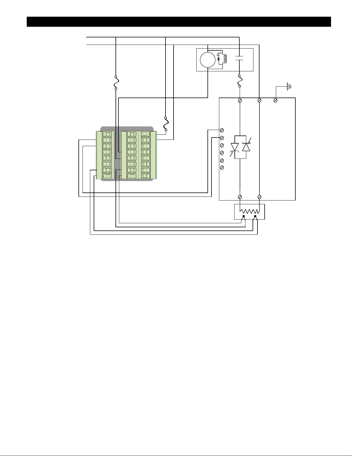
System Wiring Example
Ó
1
Ó
2
Ó
3
L1
Neutral
Coil
+
X1
-
W1
+
Y1
T1
S1
R1
L4
K4
T2
S2
R2
PM6C2CA - ALAJAAA
98
99
CC
CA
CB
B5
D6
D5
5
6
7
8
9
10
DA10-24C0-0000
Heater
Find Quality Products Online at: sales@GlobalTestSupply.com
www.GlobalTestSupply.com
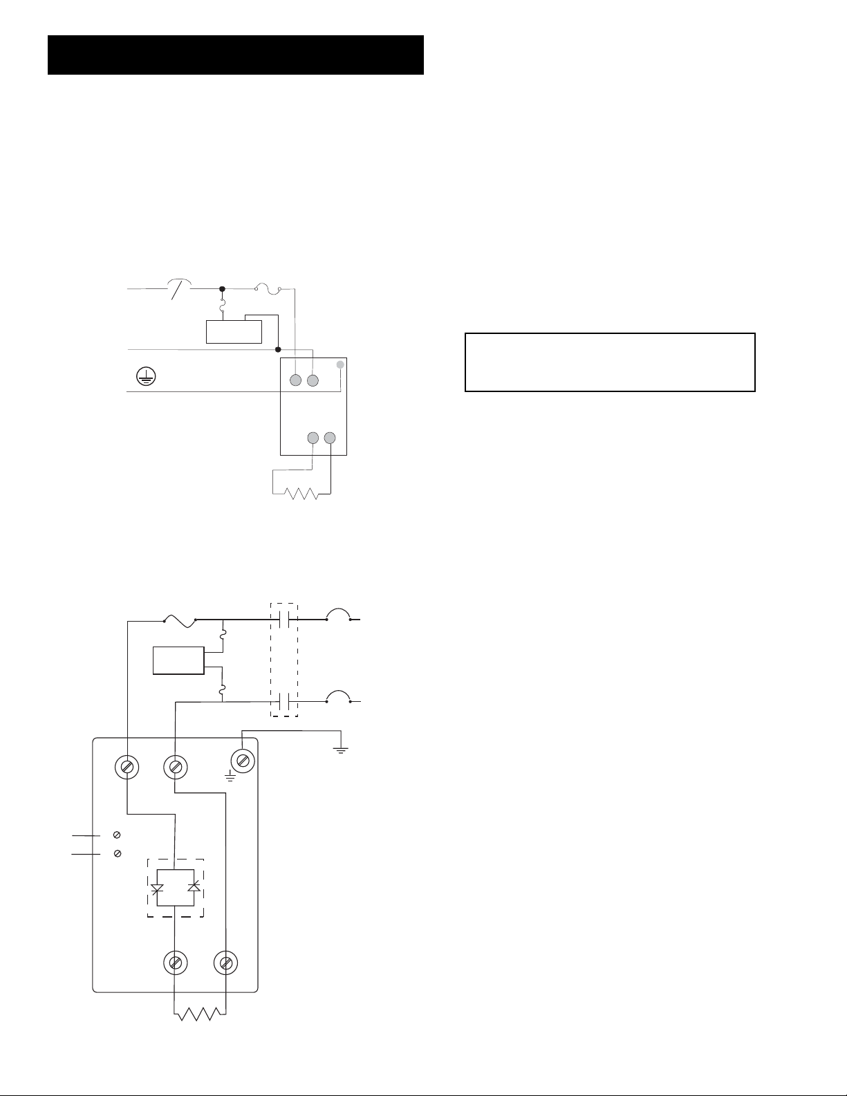
Required External EMI Filters for
DIN-A-MITE with More than 6 A Loads
An external EMI filter must be used in conjunction with the DINA-MITE for loads in excess of six amperes (6A) at 150 to 250 kHz.
Without a filter applied, the DIN-A-MITE does not comply with
the conducted emissions standard for loads above 6A at 150 to 250
KHz.
Watlow has verified that two types of filters will suppress
electromagnetic interference (EMI) created by the DIN-A-MITE
power controller to within the CE requirements.
A tank filter supplied by Crydom or Watlow, installed across the
power lines, suppresses EMI on the power lines. See figure below.
See Table 1 for the correct filter.
Description Crydom Watlow
Filter Filter
Single-phase, 230VÅ (ac) 1F25 14-0019
Table 1— DIN-A-MITE EMI Filters.
çWARNING:
The tank filters specified may suppress desirable communications carried
on power lines in the 150 to 250 kHz region. The filters may suppress
carrier current such as that used for infant monitors and medical alert
systems. Verify that suppressed carrier current or other desirable
communications on power lines creates no hazard to people or property.
Failure to observe this warning could result in damage to property, and
injury or death for personnel.
ÓWARNING:
All filter installation and wiring must be performed by qualified personnel,
and conform to local and national electrical codes. Failure to observe this
warning could result in damage to property, and injury or death for
personnel.
WATLOW DIN-A-MITE Style A User's Guide 5
USA 120V, Europe 230V
USA 240V+, Europe 400V
L1
L2
3
Limit Control
Contacts
(if required)
Semiconductor
Fuses
4
Phase-to-phase
200VÅ (ac)
and above
Heater
2
1
5
6
7
8
9
10
–
+
Ground
Tank
Filter
5A
5A
A
Breaker or
fused disconnect
N
PE
A protective earth (PE) connection
is required.
Semiconductor Fuse
5A
Filter
1
2
DIN-A-MITE
Tank Filter Wiring.
Heater
4
3
Find Quality Products Online at: sales@GlobalTestSupply.com
www.GlobalTestSupply.com

DIN-A-MITE Style A, solid-state power controller
Part Number D
A 1 0 - __ __ __ __ - 0 __ __ __
Phase
1 = 1-phase, 1 controlled leg
Cooling & Current Rating
0 = Natural convection current rating
18A @ 50°C
Note: See derating curve for current rating
at other temperatures.
Line & Load Voltage
02 = 24 to 48VÅ (ac)
24 = 120 to 240VÅ (ac)
60 = 277 to 600VÅ (ac)
Input Type
C0 = 4.5 to 32VÎ (dc) contactor
K1 = 24 to 48VÅ (ac) contactor
K2 = 100 to 120VÅ (ac) contactor
K3 = 200 to 240VÅ (ac) contactor
F0 = 4 to 20 mAÎ (dc) proportional
Manual Language
0 = English
1 = German
2 = Spanish
3 = French
Custom Parts Designation
00 = Standard parts
Output Rating Curve
30
25
20
15
10
5
0
25 30 35 40 45 50 55 60 65 70 75 80 85
Current (Amps) into
a Resistive Load
Maximum Ambient Temperature (°C)
Ratings at 100% on
Specifications
Ordering Information
Operator Interface
• Command signal input
• Input indicator LED
Amperage
• Single-phase, 18 A output maximum at 50°C (122°F) into a resistive
load. See the output rating curve.
• Maximum I
2
t for fusing: 4,000 A2sec
• Holding current: 100 mA minimum
• Latching current: 200 mA minimum
• Power dissipation: 1.2 watts per amp switched
• 200KA SCCR with recommended fusing
Line Voltage
• 24 to 48VÅ (ac) units: 20VÅ (ac) minimum to 53VÅ (ac) maximum
• 120 to 240VÅ (ac) units: 48VÅ (ac) minimum to
265 VÅ (ac) maximum
• 277 to 600VÅ (ac) units: 85VÅ (ac) minimum to 660VÅ (ac)
maximum
• Off-state leakage: 1 mA at 25°C (77°F) maximum
• 50/60 Hz. independent
Control Mode, Zero Cross
• Input Control Signal Type C: VÎ (dc) input contactor.
To increase service life, the cycle time should be less
than 3 seconds.
• Input Control Signal Type K: VÅ (ac) input contactor. To increase
service life, the cycle time should be less than 3 seconds.
• Input Control Signal Type F: 4 to 20 mAÎ (dc)
proportional variable time base control.
Input Command Signal
• AC contactor
24 VÅ ±10%, 120VÅ +10%/-25%, 240VÅ (ac) +10%/-25% @ 25 mA
maximum per controlled leg
• Do not use the DIN-A-MITE Vac-input models with a temperature
controller that includes an RC snubber circuit across its output.
Remove the RC snubber circuit before placing the DIN-A-MITE into
service.
• DC Contactor
4.5 to 32VÎ (dc): maximum current @ 4.5VÎ (dc) is 8 mA per leg.
• Loop powered linear current
4 to 20 mAÎ (dc): loop-powered. Input Type F0 option only.
(Requires current source with 8.0VÎ (dc) available. No more than two
DIN-A-MITE inputs can be connected in series.)
Agency Approvals
•ROHS
•UL®508-listed and C-UL®File E73741
• CE with proper filter:
EN 61326 Industrial Immunity Class A Emissions
EN 50178 Safety requirements
Input Terminals
• Compression: Will accept 0.2 to 1.5 mm
2
(24 to 16 AWG) wire
•Torque to 0.5 Nm (4.4 in-lb) maximum with a 3.5 mm (1/8 in) blade
screwdriver
• Strip 5.5 mm (0.22 in)
• Line and load wire insulation rating must be 75C or higher, copper
conductor only
Line and Load Terminals
• Compression: Will accept 0.75 to 10 mm
2
(18 to 8 AWG) wire
•Torque to 1.4 Nm (12 in-lb) with a 6.4 mm (1/4 in) blade screwdriver,
or Type 1A #2 Pozi driver
• Retorque after 48 hours to minimize wire cold flow
• Retorque line and load terminals every 3 to 6 months
• Strip 6.4 mm (0.25 in)
Operating Environment
• Up to 80°C. See the output rating curve chart for your application.
• 0 to 90% RH (relative humidity), non-conden sing
6 WATLOW DIN-A-MITE Style A User's Guide
• Installation only tested to 3,000 meters
• Units are suitable for “Pollution degree 2”
• Contactor V‡ (ac/dc) To increase service life, the cycle time should be less
than three seconds
Mounting
Options include DIN rail or standard back panel mounting.
• The DIN rail specification is: DIN EN 50022, 35 mm by 7.5 mm
• Minimum clipping distance: 34.8 mm (1.37 in)
• Maximum clipping distance: 35.3 mm (1.39 in)
• Mount the cooling fins vertically
Weight
• 323 grams (11.40 oz)
Recommended Fuse and Fuse Holder
Fuse
Watlow
Semiconductor
Bussmann
Semiconductor
Watlow
Combination
Bussmann
Combination
20A 17-8020 FWC20A10F 0808-0325-0020 DFJ20
25A 17-8025 FWC25A14F 0808-0325-0025 DFJ25
32A 17-8030 FWP32A14F 0808-0325-0030 DFJ30
40A 17-8040 FWP40A14F - - - - - - - -
Holders (single)
Fuse Watlow Bussmann Ferraz
Bussmann
Combination
20A 17-5110 - - - - USM1i - - - 25A 17-5110 - - - - USM1i - - - 32A 17-5114 - - - - USM141i - - - 40A 17-5114 - - - - USM141i - - - -
15 to 30A 0808-0326-1530 - - - - - - - - CH30J1i
Find Quality Products Online at: sales@GlobalTestSupply.com
www.GlobalTestSupply.com

WATLOW DIN-A-MITE Style A User's Guide 7
DIN-A-MITE®“A” Power Controller
WATLOW Electric Manufacturing Company
1241 Bundy Blvd. Winona, MN 55987 USA
Declares that the following products:
Designation: DIN-A-MITE® “A” Power Control
Model Numbers: DA10 – (02, 24 or 60)(C0, C1, C2, K1, K2, K3, F0 or F1) – 0 (followed by any 3 numbers or letters.)
Classification: Power Control, Installation Category III, Pollution degree 2, IP20
Rated Voltage: 24 to 600 V
~ (ac), 50 or 60 Hz
Meets the essential requirements of the following European Union Directives by using the relevant standards show below to indicate compliance.
2004/108/EC Electromagnetic Compatibility Directive
EN 61326-1: 2013 Electrical equipment for measurement, control and laboratory use - EMC requirements (Industrial Immunity, Class
A
1,2,4
Emissions) Not for use in a Class B environment without additional filtering.
EN 61000-4-2:2009 Electrostatic Discharge Immunity
EN 61000-4-3:2010 Radiated Field Immunity 10V/m 80 MHz- 1GHz, 3V/m 1.4GHz-2.7GHz
EN 61000-4-4:2012 Electrical Fast-Transient / Burst Immunity
EN 61000-4-5:2006 Surge Immunity (Reviewed to IEC 61000-4-5 2014)
EN 61000-4-6:2014 Conducted Immunity
EN 61000-4-11:2004 Voltage Dips, Short Interruptions and Voltage Variations
EN 61000-3-2:2009 Harmonic Current Emissions (Reviewed to IEC 61000-3-2 2014)
EN 61000-3-3:2013 Voltage Fluctuations and Flicker3
NOTES
1
Use of an external filter is required to comply with conducted emissions limits. See note 4 below.
2
A Line Impedance Stabilization Network (LISN) was used for conducted emissions measurements.
3
To comply with flicker requirements, command signal models F0 and F1 will require a reduced source impedance. Cycle time on ON/OFF models C0,
C1, C2 and K1, K2, K3 may need to be up to 175 seconds at 16A.
2006/95/EC Low-Voltage Directive
EN 50178:1997 Electronic equipment for use in power installations.
Per 2012/19/EU W.E.E.E Directive Please Recycle Properly.
Compliant with 2011/65/EU RoHS2 Directive
4
Required External EMI Filters for DIN-A-MITE with More Than 6 Amp Loads
An external ElectroMagnetic Interference (EMI) filter must be used in conjunction with the DIN-A- MITE for loads in excess of six amperes (6A) at 150
to 250 KHz.
Watlow has verified that a tank filter will suppress EMI created by SCR power controllers to comply with the conducted emissions limits
Joe Millanes Winona, Minnesota, USA
Name of Authorized Representative Place of Issue
Director of Operations September 2014
Title of Authorized Representative Date of Issue
Declaration of Conformity
ISO 9001since 1996.
Signature of Authorized Representative
Find Quality Products Online at: sales@GlobalTestSupply.com
www.GlobalTestSupply.com
 Loading...