

Page 1

Series D8
User’s Guide
Watlow Anafaze
1241 Bundy Blvd.
Winona, MN 55987
Customer Service:
Phone....... 1-800-414-4299
Fax ........... 1-800-445-8992
Technical Support:
Phone....... (507) 494-5656
Fax ........... (507) 452-4507
Email ........ wintechsupport@watlow.com
Part No. 0600-3120-2000 Rev. B
November 2008
Page 2

Copyright © 2005, Watlow Anafaze, Incorporated
Information in this manual is subject to change without notice. No part of this publication may be
reproduced, stored in a retrie val system, or transmitted in an y form without written permission
from Watlow Anafaze.
Anafaze is a re gistered trademark of Watlow Electric Manuf acturing Compan y. De viceNet is a
trademark of the Open DeviceNet Vendor Association, Inc. UL is a registered trademark of Underwriters Laboratories, Inc. All other trademarks are the property of their respective owners.
RSNetWorx, RSLinx and RSLogix are trademarks of Rockwell Software Inc.
DeviceNet is a trademark of the Open DeviceNet Vendors Association.
Warranty
Watlow Anafaze, Incorporated w arrants that the products furnished under this Agreement will be
free from defects in material and w orkmanship for a period of three years from the date of shipment. The Customer shall provide notice of any defect to Watlow Anafaze, Incorporated within one
week after the Customer's disco very of such defect. The sole obligation and liability of Watlow
Anafaze, Incorporated under this w arranty shall be to repair or replace, at its option and without
cost to the Customer, the defective product or part.
Upon request by Watlow Anafaze, Incorporated, the product or part claimed to be defecti ve shall
immediately be returned at the Customer's e xpense to Watlow Anafaze, Incorporated. Replaced or
repaired products or parts will be shipped to the Customer at the e xpense of Watlow Anafaze,
Incorporated.
There shall be no w arranty or liability for an y products or parts that ha ve been subject to misuse,
accident, negligence, failure of electric power or modification by the Customer without the writte
approval of Watlow Anafaze, Incorporated. Final determination of w arranty eligibility shall be
made by Watlow Anafaze, Incorporated. If a w arranty claim is considered in valid for an y reason,
the Customer will be char ged for services performed and e xpenses incurred by Watlow Anafaze,
Incorporated in handling and shipping the returned unit.
If replacement parts are supplied or repairs made during the original w arranty period, the warranty
period for the replacement or repaired part shall terminate with the termination of the w arranty
period of the original product or part.
The foregoing warranty constitutes the sole liability of Watlow Anafaze, Incorporated and the Customer's sole remedy with respect to the products. It is in lieu of all other w arranties, liabilities, and
remedies. Except as thus pro vided, Watlow Anafaze, Inc., disclaims all w arranties, e xpress or
implied, including any warranty of merchantability or fitness for a particular purpose
Please Note
: External safety devices must be used with this equipment.
Page 3

Table of Contents
List of Figures ix
List of Tables xiii
1 System Overview 1
Manual Contents 1
Getting Started 2
Safety Symbols 2
Initial Inspection 2
Product Features 2
D8 Parts List 5
Technical Description 6
D8 6
TB50 8
D8 Cabling 8
Safety 8
External Safety Devices 8
Power-Fail Protection 9
2 Installation 11
Typical Installation 12
Mounting Controller Components 12
Recommended Tools 13
Mounting the Controller 13
Mounting the TB50 16
Mounting the Power Supply 18
Mounting the Dual DAC or Serial DAC Module 19
System Wiring 20
Wiring Recommendations 20
Noise Suppression 21
Ground Loops 22
Power Connections 23
Wiring the Power Supply 23
Connecting the TB50 to the D8 25
Testing the System 26
TB50 or TB18 Test 26
Digital Output Test 26
Digital Input Test 27
Sensor Wiring 27
Input Wiring Recommendations 28
Thermocouple Connections 29
Doc. 0600-3120-2000 Watlow Anafaze i
Page 4

Table of Contents Series D8 User’s Guide
RTD Input Connections 30
Voltage Input Connections 30
Current Input Connections 30
Wiring Control and Digital I/O 31
Output Wiring Recommendations 31
Cable Tie Wraps 31
Digital Outputs 31
Digital Inputs 35
TB18 Connections 36
TB50 Connections 37
Analog Outputs 38
Wiring the Dual DAC 38
Wiring the Serial DAC 39
Connecting the D8 to a DeviceNet Network 40
Connector Type 40
Pinout 41
Network Length 42
Baud Rate (Data Rate) 42
Node Address (MAC ID) 42
Status Indicators 43
3 Communicating by DeviceNet 45
Accessing Data with a DeviceNet Master 45
Software 45
About The Electronic Data Sheet (EDS) 46
Configuring a D8 Using RSNetWorx 46
Registering the D8 without an EDS File 47
Registering the D8 with the Watlow EDS File 48
Mapping Polled I/O Data 50
Adding the D8 to the Master's Scanlist 50
Assigning PLC Addresses 51
Sample Ladder Logic 53
Accessing Polled I/O Data 53
Setting a Value with an Explicit Message 55
Reading a Value with an Explicit Message 57
Setting Parameters via DeviceNet 58
Non-Numeric Settings 58
Bit-Wise Values 59
Decimal Placement for Numeric Values 59
Decimal Placement for Percentage Values 60
D8 DeviceNet Overview 60
Master/Slave Connections 60
Addressing 61
Data Types 61
DeviceNet Objects 61
Identity Object 61
Message Router Object 62
DeviceNet Object 63
Assembly Object 63
Connection Object 66
Input Object 67
Output Object 68
Control Object 70
Alarm Object 71
ii Watlow Anafaze Doc. 0600-3120-2000
Page 5

Series D8 User’s Guide Table of Contents
PV Retransmit Object 72
Ratio Object 73
Cascade Object 74
Global Object 75
4 Operation and Setup 77
General Navigation Map 77
Keypad 79
Displays 80
Loop Display 80
Alarm Displays 81
Job Display 83
Changing the Set Point 84
How to Manually Change the Set Point 84
Other Methods of Changing the Set Point 84
Changing the Control Mode and Output Power 85
Accessing and Navigating the Setup Menus 86
How to Access the Setup Menus 86
How to Edit a Setup Parameter 86
Setting Up Closed-Loop Control 87
Feedback 87
Control Algorithm 87
Control Output Signal Forms 87
Heat and Cool Outputs 87
How to Set Up Closed-Loop Control 88
Setting Up a Process Input 88
Input Scaling 88
Input Scaling Example: 4 to 20 mA Sensor 89
Input Scaling Example: 0 to 5 Vdc Sensor 90
Autotuning 91
How Does Autotuning Work? 91
Prerequisites 92
How to Autotune a Loop 92
Setting Up Alarms 93
Failed Sensor Alarms 93
Process Alarms 95
Global Alarm 97
Setting Up Process Variable Retransmit 97
How to Set Up Process Variable Retransmit 98
Process Variable Retransmit Example: Data Logging 98
Setting Up Cascade Control 100
How the Secondary Set Point is Determined 100
Proportional-Only Control on the Primary Loop 101
How To Set Up Cascade Control 102
Cascade Control Example: Water Tank 102
Setting Up Ratio Control 104
How to Set Up Ratio Control 105
Ratio Control Example: Diluting KOH 105
Setting Up Differential Control 106
How to Set Up Differential Control 107
Differential Control Example: Thermoforming 107
Setting Up Remote Analog Set Point 107
How to Set Up a Remote Analog Set Point 108
Remote Analog Set Point Example: Changing a Set Point with a PLC 108
Doc. 0600-3120-2000 Watlow Anafaze iii
Page 6

Table of Contents Series D8 User’s Guide
5 Tuning and Control 111
Control Algorithms 111
On/Off Control 112
Proportional Control (P) 112
Proportional and Integral Control (PI) 113
Proportional, Integral and Derivative Control (PID) 114
Heat and Cool Outputs 114
Setting Up and Tuning PID Loops 115
Proportional Band Settings 115
Integral Settings 115
Derivative Settings 116
General PID Constants by Application 117
Proportional Band Only (P) 117
Proportional with Integral (PI) 117
Proportional and Integral with Derivative (PID) 117
Control Outputs 118
Output Control Signals 118
Output Filter 120
Reverse and Direct Action 120
6 Menu and Parameter Reference 121
Operator Parameters 121
Set Point 122
Mode 122
Heat/Cool Output 122
Process Variable 123
Overview of the Setup Menus 123
Global Setup Menu 125
Load Setup From Job 125
Save Setup As Job 125
BCD Job Load 126
BCD Job Load Logic 126
Mode Override 127
Mode Override Digital Input Active 128
Power Up Alarm Delay 128
Power Up Loop Mode 128
Keypad Lock 129
Thermocouple Short Alarm 129
AC Line Frequency 129
Digital Output Alarm Polarity 129
MAC ID 130
Baud Rate 130
Module LED 130
Network LED 130
Bus Off Count 130
Model and Firmware Version 131
Input Menu 131
Input Type 131
Loop Name 132
Input Units 132
Calibration Offset 132
Reversed Thermocouple Detection 133
Display Format 133
Input Range High 134
iv Watlow Anafaze Doc. 0600-3120-2000
Page 7

Series D8 User’s Guide Table of Contents
Input High Signal 134
Input Range Low 135
Input Low Signal 135
Input Filter 135
Control Menu 136
Heat/Cool Proportional Band 136
Heat/Cool Integral 137
Heat/Cool Derivative 137
Heat/Cool Manual Reset 137
Heat/Cool Filter 137
Hysteresis 138
Restore Automatic Mode 138
Output Menu 139
Heat/Cool Output Type 139
Heat/Cool Cycle Time 140
Heat/Cool SDAC Signal 140
Heat/Cool SDAC Low Signal 140
Heat/Cool SDAC High Signal 140
Heat/Cool Action 141
Heat/Cool Power Limit 141
Heat/Cool Power Limit Time 141
Sensor Fail Heat/Cool Output 142
Open Thermocouple Heat/Cool Output Average 142
Heat/Cool Output Curve 143
Alarms Menu 143
Alarm High Set Point 143
Alarm High Function 144
Alarm High Output 144
High Deviation Value 145
High Deviation Function 145
High Deviation Output 145
Low Deviation Value 145
Low Deviation Function 145
Low Deviation Output 146
Alarm Low Set Point 146
Alarm Low Function 146
Alarm Low Output 146
Alarm Hysteresis 147
Alarm Delay 147
Process Variable Retransmit Menu 148
Heat/Cool Output Retransmit 148
Heat/Cool Retransmit Low Process Variable 148
Heat/Cool Retransmit High Process Variable 148
Cascade Menu 149
Cascade Primary Loop 149
Cascade Low Set Point 149
Cascade High Set Point 149
Ratio Menu 150
Ratio Master Loop 150
Ratio Low Set Point 150
Ratio High Set Point 151
Control Ratio 151
Ratio Set Point Differential 151
I/O Tests Menu 151
Doc. 0600-3120-2000 Watlow Anafaze v
Page 8

Table of Contents Series D8 User’s Guide
Digital Inputs 152
Keypad Test 152
Display Test 152
Test Digital Output 1 to 20 153
Parameters Only Available via Communications 153
Alarm Acknowledge 153
Alarm Enable 153
Alarm Function 154
Alarm Status 154
Ambient Sensor Reading 155
Heat/Cool Output Action for Watchdog Inactivity Fault 156
7 Troubleshooting and Reconfiguring 157
When There is a Problem 157
Returning a Unit 158
Troubleshooting the Controller 158
Process Alarms 159
Ambient Warning 160
Failed Sensor Alarms 160
System Alarms 160
Other Behaviors 161
Reading the DeviceNet Indicator Lights 162
Corrective and Diagnostic Procedures 163
Low Power 163
Battery Dead 163
H/W Error: Gain or Offset 164
H/W Error: Ambient 165
Keys Do Not Work 166
Checking Analog Inputs 166
Earth Grounding 167
Testing Control Output Devices 168
Testing the TB18 and TB50 168
Testing Control and Digital Outputs 168
Testing Digital Inputs 169
Clearing the RAM 169
Replacing the Flash Memory Chip 170
Installing Scaling Resistors 172
Input Circuit 172
Current Inputs 173
Voltage Inputs 174
RTD Inputs 175
Scaling and Calibration 176
Configuring Serial DAC Outputs 176
Configuring Dual DAC Outputs 177
8 Specifications 179
System Specifications 179
Physical Specifications 179
Inputs 185
Outputs 187
Power Supply 189
Dual DAC Specifications 191
Dual DAC Inputs 192
Dual DAC Analog Outputs 192
vi Watlow Anafaze Doc. 0600-3120-2000
Page 9

Series D8 User’s Guide Table of Contents
Serial DAC Specifications 193
Serial DAC Inputs 194
Serial DAC Analog Outputs 195
Glossary 197
Index 205
Menu Structure 213
Doc. 0600-3120-2000 Watlow Anafaze vii
Page 10

Table of Contents Series D8 User’s Guide
viii Watlow Anafaze Doc. 0600-3120-2000
Page 11

1 System Overview
Figure 1.1—D8 Standard Parts List 5
Figure 1.2—D8 Special Inputs Parts List 6
Figure 1.3—D8 Rear Views 6
Figure 1.4—D8 Front Panel 7
Figure 1.5—TB50 8
List of Figures
2 Installation
Figure 2.1—D8 System Components 12
Figure 2.2—Module Dimensions and Clearance 14
Figure 2.3—Wiring Clearances 14
Figure 2.4—Mounting Bracket 15
Figure 2.5—Mounting the TB50 16
Figure 2.6—TB50 Mounted on a DIN Rail (Front) 16
Figure 2.7—TB50 Mounted on DIN Rail (Side) 17
Figure 2.8—Mounting a TB50 with Standoffs 17
Figure 2.9—D8 Power Supply Mounting Bracket 18
Figure 2.10—Dual DAC and Serial DAC Dimensions 19
Figure 2.11—D8 Series Controller with TB50 23
Figure 2.12—Power Connections with the D8 Power Supply 25
Figure 2.13—Thermocouple Connections 29
Figure 2.14—RTD Connections 30
Figure 2.15—Voltage Signal Connections 30
Figure 2.16—Current Signal Connections 30
Figure 2.17—Digital Output Wiring 32
Figure 2.18—Sample Heat, Cool and Alarm Output Connections 33
Figure 2.19—Output Connections Using External Power Supply 34
Figure 2.20—TB50 Watchdog Timer Output 34
Figure 2.21—TB18 Watchdog Timer Output 34
Figure 2.22—Wiring Digital Inputs 35
Figure 2.23—Dual DAC with Current Output 38
Figure 2.24—Dual DAC with Voltage Output 39
Figure 2.25—Single/Multiple Serial DACs 40
Figure 2.26—DeviceNet Connector 40
Figure 2.27—DeviceNet Connector 41
Figure 2.28—Pinout 41
Figure 2.29—D8 Side with Rotary Switches 43
0600-3120-2000 Watlow Anafaze ix
Page 12

List of Figures Series D8 User’s Guide
3 Communicating by DeviceNet
Figure 3.1—RSNetWorx On-line with Found Devices 47
Figure 3.2—The D8 Registered in RSNetWorx 48
Figure 3.3—D8 Properties in RSNetWorx 49
Figure 3.4—Parameters Tab 50
Figure 3.5—Adding the D8 to the Scanlist 51
Figure 3.6—Scanner Input Properties 52
Figure 3.7—Advanced Mapping Dialog Box 53
Figure 3.8—Using Scanned Data in Logic 54
Figure 3.9—Contents of the PLC Memory 55
Figure 3.10—Explicit Write in Ladder 56
Figure 3.11—Explicit Read in Ladder 58
Figure 3.12—D84 Produced Static Input 65
Figure 3.13— D84 Consumed Static Output 65
Figure 3.14—D88 Produced Static Input 65
Figure 3.15—D88 Consumed Static Output 66
4 Operation and Setup
Figure 4.1—General Navigation Map 78
Figure 4.2—Keypad Navigation 79
Figure 4.3—Loop Display 80
Figure 4.4—Loop Display with Alarm Code 81
Figure 4.5—Display for Failed Sensor Alarm 81
Figure 4.6—Input Scaling 89
Figure 4.7—Activation and Deactivation of Process Alarms 96
Figure 4.8—Application Using Process Variable Retransmit 99
Figure 4.9—Secondary Set Point When Primary Loop Has Heat and Cool Outputs
101
Figure 4.10—Secondary Set Point When Primary Loop Has Heat Output Only 101
Figure 4.11—Example Application Using Cascade Control 103
Figure 4.12—Relationship of Secondary Loop Set Point to Primary Loop Process
Variable in Cascade Example 104
Figure 4.13—Relationship Between the Process Variable on the Master Loop and the
Set Point of the Ratio Loop 105
Figure 4.14—Application Using Ratio Control 106
5 Tuning and Control
Figure 5.1—On/Off Control 112
Figure 5.2—Proportional Control 113
Figure 5.3—Proportional and Integral Control 113
Figure 5.4—Proportional, Integral and Derivative Control 114
Figure 5.5—Time Proportioning and Distributed Zero Crossing Waveforms 118
6 Menu and Parameter Reference
Figure 6.1—Operator Parameter Navigation 121
Figure 6.2—Setup Menus and Parameters 124
Figure 6.3—Linear and Nonlinear Outputs 143
x Watlow Anafaze Doc. 0600-3120-2000
Page 13

Series D8 User’s Guide List of Figures
7 Troubleshooting and Reconfiguring
Figure 7.1—Removal of Electronics Assembly from Case 170
Figure 7.2—Screw Locations on PC Board 171
Figure 7.3—Location of Flash Memory Chip 171
Figure 7.4—Input Circuit 173
Figure 7.5—Serial DAC Voltage and Current Jumper Positions 176
Figure 7.6—Dual DAC 177
8 Specifications
Figure 8.1—D8 Module Dimensions 180
Figure 8.2—Module Dimensions and Clearance 181
Figure 8.3—TB50 Dimensions 182
Figure 8.4—TB50 Dimensions with Straight SCSI Cable 183
Figure 8.5—TB50 Dimensions with Right-Angle SCSI Cable 184
Figure 8.6—Power Supply Dimensions (Bottom View) 190
Figure 8.7—Dual DAC Dimensions 191
Figure 8.8—Serial DAC Dimensions 193
Glossary
Index
Menu Structure
Doc. 0600-3120-2000 Watlow Anafaze xi
Page 14

List of Figures Series D8 User’s Guide
xii Watlow Anafaze Doc. 0600-3120-2000
Page 15

2 Installation
Table 2.1—Cable Recommendations 21
Table 2.2—Power Connections 24
Table 2.3—TB1 Connections 28
Table 2.4—Digital Output States and Values Stored in the Controller 32
Table 2.5—Digital Input States and Values Stored in the Controller 35
Table 2.6—TB18 Connections 36
Table 2.7—TB50 Connections 37
Table 2.8—DeviceNet Connector 41
Table 2.9—Maximum Network Speed 42
Table 2.10—Module Status Indicator Light 44
Table 2.11—Network Status Indicator Light 44
List of Tables
3 Communicating by DeviceNet
Table 3.1—Number of Bytes 48
Table 3.2—Outbound Transaction Header 57
Table 3.3—Explicit Message Body 57
Table 3.4—Number of Decimal Places for Numeric Values via Logic 59
Table 3.5—Address Components 61
Table 3.6—Elementary Data Types 61
Table 3.7—Identity Class and Services 62
Table 3.8—Identity Instance Attributes 62
Table 3.9—Message Router Class and Services 62
Table 3.10—Message Router Instance Attributes 62
Table 3.11—DeviceNet Class and Services 63
Table 3.12—DeviceNet Class Attributes 63
Table 3.13—DeviceNet Instance Attributes 63
Table 3.14—Assembly Class and Services 64
Table 3.15—Assembly Instance Attributes 64
Table 3.16—Connection Class and Services 66
Table 3.17—Connection Instance Attributes 66
Table 3.18—Input Class and Services 67
Table 3.19—Input Class Attributes (Instance 0) 67
Table 3.20—Input Instance Attributes (Instances 1 to 4 or 8) 68
Table 3.21—Output Class and Services 68
Table 3.22—Output Class Attributes (Instance 0) 69
Table 3.23—Output Instance Attributes (Instances 1 to 4 or 8) 69
Doc. 0600-3120-2000 Watlow Anafaze xiii
Page 16

List of Tables Series D8 User’s Guide
Table 3.24—Control Class and Services 70
Table 3.25—Control Class Attributes (Instance 0) 70
Table 3.26—Control Instance Attributes (Instances 1 to 4 or 8) 70
Table 3.27—Alarm Class and Services 71
Table 3.28—Alarm Class Attributes (Instance 0) 71
Table 3.29—Alarm Instance Attributes (Instances 1 to 4 or 8) 71
Table 3.30—PV Retransmit Class and Services 72
Table 3.31—PV Retransmit Class Attributes (Instance 0) 72
Table 3.32—PV Retransmit Instance Attributes (Instances 1 to 4 or 8) 73
Table 3.33—Ratio Class and Services 73
Table 3.34—Ratio Class Attributes (Instance 0) 73
Table 3.35—Ratio Instance Attributes (Instances 1 to 4 or 8) 74
Table 3.36—Cascade Class and Services 74
Table 3.37—Cascade Class Attributes (Instance 0) 74
Table 3.38—Cascade Instance Attributes (Instances 1 to 4 or 8) 75
Table 3.39—Global Class and Services 75
Table 3.40—Global Class Attributes (Instance 0) 75
Table 3.41—Global Instance Attributes (Instance 1) 76
4 Operation and Setup
Table 4.1—Control Modes 80
Table 4.2—Alarm Codes and Messages for Process and Failed Sensor Alarms 82
Table 4.3—System Alarm Messages 83
Table 4.4—Input Readings 90
Table 4.5—Scaling Values 90
Table 4.6—Input Readings and Calculations 91
Table 4.7—Scaling Values 91
Table 4.8—Parameters Settings for Process Variable Retransmit Example 99
Table 4.9—Parameter Settings for the Primary Loop in the Cascade Example 103
Table 4.10—Parameter Settings for the Secondary Loop in the Cascade Example
103
Table 4.11—Ratio Control Settings for the Ratio Loop (Loop 2) in the Example 106
Table 4.12—Parameter Settings for the Ratio Loop (Loop 2) for the Example 107
Table 4.13—Parameters Settings for the Master Loop (Loop 1) in the Example 108
Table 4.14—Parameter Settings for the Ratio Loop (Loop 2) in the Example 109
5 Tuning and Control
Table 5.1—Proportional Band Settings 115
Table 5.2—Integral Term and Reset Settings 116
Table 5.3—Derivative Term Versus Rate 116
Table 5.4—General PID Constants 117
6 Menu and Parameter Reference
Table 6.1—Control Modes 122
Table 6.2—D8 Setup Menus 123
Table 6.3—Values for BCD Job Load 126
Table 6.4—Digital Input States Required to Load Each Job 127
xiv Watlow Anafaze Doc. 0600-3120-2000
Page 17

Series D8 User’s Guide List of Tables
Table 6.5—Power Up Loop Modes 128
Table 6.6—Digital Output Alarm Polarity 130
Table 6.7—Input Types and Ranges 131
Table 6.8—Characters for the Loop Name and Input Units Parameters 132
Table 6.9—Calibration Offset Ranges 133
Table 6.10—Display Formats 134
Table 6.11—Proportional Band Values 136
Table 6.12—Values for the Control Hysteresis and Deviation Alarm Parameters 138
Table 6.13—Heat and Cool Output Types 139
Table 6.14—Alarm Functions 144
Table 6.15—Values for Alarm Hysteresis 147
Table 6.16—Bit Positions for Alarm Enable and Alarm Function 154
Table 6.17—Bit Positions for Alarm Status and Alarm Acknowledge 155
Table 6.18—System Status Bits 155
Table 6.19—DeviceNet Value for Watchdog Inactivity Fault 156
7 Troubleshooting and Reconfiguring
Table 7.1—Operator Response to Process Alarms 160
Table 7.2—Other Symptoms 161
Table 7.3—Module Status Indicator States and Descriptions 162
Table 7.4—Network Status Indicator Light 163
Table 7.5—Resistor Values for Current Inputs 173
Table 7.6—Resistor Locations for Current Inputs 173
Table 7.7—Resistor Values for Voltage Inputs 174
Table 7.8—Resistor Locations for Voltage Inputs 174
Table 7.9—Resistor Locations for RTD Inputs 175
Table 7.10—Dual DAC Jumper Settings 177
8 Specifications
Table 8.1— Agency Approvals / Compliance 179
Table 8.2—Environmental Specifications 179
Table 8.3—D8 with Straight SCSI 180
Table 8.4—D8 Connections 181
Table 8.5—TB50 Physical Dimensions 181
Table 8.6—TB50 Connections 182
Table 8.7—TB50 with Straight SCSI 182
Table 8.8—TB50 with Right Angle SCSI 183
Table 8.9—Analog Inputs 185
Table 8.10—Thermocouple Range and Resolution 186
Table 8.11—RTD Range and Resolution 186
Table 8.12—Input Resistance for Voltage Inputs 186
Table 8.13—Digital Inputs 187
Table 8.14—Digital Outputs Control / Alarm 188
Table 8.15—5 Vdc Output (Power to Operate Solid-State Relays) 188
Table 8.16—Communications 188
Table 8.17—D8 Power Requirements 188
Table 8.18—Power Supply Environmental Specifications 189
Table 8.19—Power Supply Agency Approvals / Compliance 189
Doc.0600-3120-2000 Watlow Anafaze xv
Page 18

List of Tables Series D8 User’s Guide
Table 8.20—Power Supply Physical Specifications 189
Table 8.21—Power Supply with Mounting Bracket 189
Table 8.22—Power Supply Inputs and Outputs 190
Table 8.23—Dual DAC Environmental Specifications 191
Table 8.24—Dual DAC Physical Specifications 191
Table 8.25—Dual DAC Power Requirements 192
Table 8.26—Dual DAC Specifications by Output Range 192
Table 8.27—Serial DAC Environmental Specifications 193
Table 8.28—Serial DAC Physical Specifications 193
Table 8.29—Serial DAC Agency Approvals / Compliance 194
Table 8.30—Serial DAC Inputs 194
Table 8.31—Serial DAC Power Requirements 194
Table 8.32—Serial DAC Analog Output Specifications 195
xvi Watlow Anafaze Doc. 0600-3120-2000
Page 19

1
System Overview
Manual Contents
This manual describes how to install, set up, and operate a D8
series controller. Each chapter covers a different aspect of
your control system and may apply to different users:
• Chapter 1: System Overview provides a component list
and summary of features for the D8 series controllers.
•
Chapter 2: Installation
on installing the D8 series controller and its peripherals.
•
Chapter 3: Communicating via DeviceNet
how to add the D8 controller to a network and how to access controller data via DeviceNet.
•
Chapter 4: Operation and Setup
about operating and setting up the D8.
•
Chapter 5: Tuning and Control
control algorithms and provides suggestions for applications.
•
Chapter 6: Menu and Parameter Reference
detailed descriptions of all menus and parameters for
controller setup.
•
Chapter 7: Troubleshooting and Reconfiguring
cludes troubleshooting, upgrading and reconfiguring
procedures for technical personnel.
•
Chapter 8: Specifications
the controller and optional components.
provides detailed instructions
explains
provides instructions
describes available
provides
in-
lists detailed specifications of
Doc. 0600-3120-2000 Watlow Anafaze 1
Page 20

Chapter 1: System Overview Series D8 User’s Guide
Getting Started
Safety Symbols
These symbols are used throughout this manual:
Initial Inspection
WARNING!
CAUTION!
NOTE!
Indicates a potentially hazardous situation
which, if not avoided, could result in death or
serious injury.
Indicates a potentially hazardous situation
which, if not avoided, could result in minor or
moderate injury or property damage.
Indicates pertinent information or an item
that may be useful to document or label for
later reference.
Accessories may or may not be shipped in the same container
as the D8, depending upon their size. Check the shipping invoice against the contents received in all boxes. If you are uncertain whether you have received all of the items you
ordered, contact your vendor or Watlow Anafaze.
Product Features
D8 series controllers offer high-performance closed-loop control.
The D8 provides four or eight independent control loops with
analog inputs — thermocouples, RTDs and process — and
features DeviceNet communications.
When used as a stand-alone controller, you may operate the
D8 via the two-line 16-character display and touch keypad.
You can also use it as the key element in a computer-supervised data acquisition and control system. The D8 can be locally or remotely controlled via its DeviceNet communications interface.
D8 features include:
2 Watlow Anafaze Doc. 0600-3120-2000
Page 21

Series D8 User’s Guide Chapter 1: System Overview
•
Direct Connection of Mixed Thermocouple Sensors:
Connect most thermocouples to the controller with no
hardware modifications. Thermocouple inputs feature
reference junction compensation, linearization, offset
calibration to correct for sensor inaccuracies, detection of
open, shorted or reversed thermocouples, and a choice of
Fahrenheit or Celsius display.
•
Accepts Resistive Temperature Detectors (RTDs):
, platinum, 0.00385-curve sensors.
Use three-wire, 100
Ω
Special inputs must be installed.
•
Automatic Scaling for Process Analog Inputs:
The D8
series automatically scales process inputs used with industrial process sensors. Enter two points, and all input
values are automatically scaled. Special inputs must be
installed.
•
Dual Outputs:
The D8 series includes both heat and cool
control outputs for each loop. Independent control parameters are provided for each output.
•
Independently Selectable Control and Output
Modes:
Set each control output to on/off, time proportioning, Serial DAC (digital-to-analog converter) or distributed zero crossing mode. Set up to two outputs per
loop for on/off, P, PI or PID control with reverse or direct
action.
•
Boost Output Function:
Set digital outputs to function
as boost on/off control in association with any alarm.
•
Flexible Alarms:
Independently set high and low alarms
and high and low deviation alarms for each loop. Alarms
can activate a digital output by themselves, or they can be
grouped with other alarms to activate an output.
•
Global Alarm Output:
Any alarm event activates the
global alarm output.
•
CPU Watchdog:
The CPU watchdog timer output noti-
fies you of system failure.
•
Keypad or DeviceNet Operation:
Set up and run the
controller from the keypad or via the DeviceNet interface.
•
DeviceNet Communications:
Connect software, programmable logic controllers and other master devices using the widely supported DeviceNet protocol. The D8 is
compliant with both the ODVA DeviceNet specification
and the Interface Guidelines for DeviceNet on Semiconductor Manufacturing Tools.
•
Multiple Job Storage:
Store up to eight jobs in the controller’s battery-backed memory. Load a job through the
keypad, digital inputs or software. Each job is a set of operating conditions, including set points and alarm limits.
Doc. 0600-3120-2000 Watlow Anafaze 3
Page 22

Chapter 1: System Overview Series D8 User’s Guide
•
Nonlinear Output Curves:
Select either of two nonlin-
ear output curves for each control output.
•
Autotuning: Use the autotune feature to set up your system quickly and easily. The internal expert system table
finds the correct PID parameters for your process.
• Low Power Shutdown: The controller shuts down and
turns off all outputs when it detects the input voltage drop
below the minimum safe operating level.
• Process Variable Retransmit: Scale a temperature or
process and convert it to an analog output for external devices such as chart recorders.
• Two-Zone Cascade Control: Control thermal systems
with long lag times, which cannot be accurately controlled with a single loop.
• Ratio or Offset Control: Control one process as a ratio
or offset of another process.
• Remote Analog Set Point: Scale an external voltage or
current source to provide a set point for a loop.
4 Watlow Anafaze Doc. 0600-3120-2000
Page 23

Series D8 User’s Guide Chapter 1: System Overview
D8 Parts List
You may have received one or more of the following components. See Figure 2.1 on page 12 for D8 configuration information.
• D8 series controller with mounting collar and brackets
• TB50 with 50-pin SCSI cable
• Power supply with mounting bracket and screws
• Serial DAC (digital-to-analog converter)
• Special input resistors (installed in D8)
• User’s guide
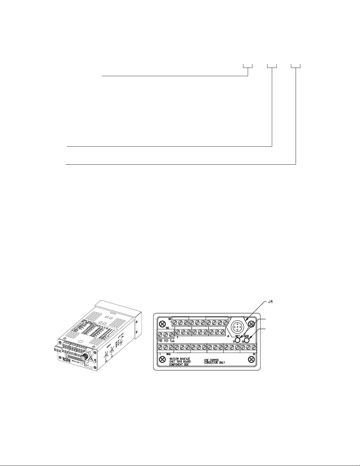
D8x0-0000-xx0x
Number of Loops
4 = 4-loop controller
8 = 8-loop controller
Digital I/O Termination
0 = TB18
1 = SCSI connector, no terminal board or cable
2 = SCSI connector, TB50 and 3-foot cable
3 = SCSI connector, TB50 and 6-foot cable
4 = SCSI connector, TB50 and 3-foot right angle cable
5 = SCSI connector, TB50 and 6-foot right angle cable
Power Supply
0 = No power supply
1 = CE Power Supply
2 = Wall mount power supply
Special Inputs
0 = Thermocouples and -10 to 60mV inputs only
X = Number of current, voltage and RTD inputs
Figure 1.1 D8 Standard Parts List
Doc. 0600-3120-2000 Watlow Anafaze 5
Page 24
Chapter 1: System Overview Series D8 User’s Guide
D8SI _ _ - _ _ - _ _
Special/Process Input Type
(Not required for thermocouple sensor inputs)
23 = RTD
43 = 0 to 10 mA dc
44 = 0 to 20 mA dc or 4 to 20 mA dc
50 = 0 to 100 mV dc
52 = 0 to 500 mV dc
53 = 0 to 1 Vdc
55 = 0 to 5 Vdc
56 = 0 to 10 Vdc
57 = 0 to 12 Vdc
Start Loop
XX = Loop number XX
End Loop
XX = Loop number XX
Figure 1.2 D8 Special Inputs Parts List
Technical Description
This section contains a technical description of each component of the D8 series controller.
D8
The D8 is housed in a 1/8-DIN panel mount package. It contains the central processing unit (CPU), random access memory (RAM) with a built-in battery, flash memory, communications, digital I/O, analog inputs, display and touch keypad.
Series D8 with SCSI Connector. Series D8 with TB18 Connector.
DeviceNet
Connector
Network LED
Indicator Light
Module LED
Indicator Light
Figure 1.3 D8 Rear Views
6 Watlow Anafaze Doc. 0600-3120-2000
Page 25

Series D8 User’s Guide Chapter 1: System Overview
The D8 has the following features:
• Keypad and two-line, 16-character display.
• Screw terminals for the power and analog inputs.
• Micro-style connector for DeviceNet.
• Input power of 12 to 24 Vdc at 1 Amp.
• 50-pin SCSI cable to connect the digital inputs and outputs to the 50-terminal block (TB50). The D8 is available
with an 18-terminal block (TB18) in place of the SCSI
connector, as shown in Figure 1.3 on page 6.
• Nonvolatile flash memory for storage of firmware and
programmable logic.
• Battery-backed storage of operating parameters. If a
power loss occurs, the operating parameters are stored in
memory. The battery has a ten-year shelf life, and it is not
used when the controller is on.
• Microprocessor control of all calculations for input signal linearization, PID control, alarms, and communications.
Front Panel Description
The display and keypad provide an intelligent way to operate
the controller. The display has 16 alphanumeric or graphic
characters per line. The eight-key keypad allows you to
change the operating parameters, controller functions and displays.
The displays show process variables, set points and output
levels for each loop. A single-loop display, scanning display
and alarm display offer a real-time view of process conditions.
For useful tips, help and menu information, press
i from any
screen.
Figure 1.4 D8 Front Panel
Doc. 0600-3120-2000 Watlow Anafaze 7
Page 26

Chapter 1: System Overview Series D8 User’s Guide
TB50
The TB50 is a screw-terminal interface for control wiring. It
allows you to connect power controllers and other discrete I/O
devices to the D8. The screw terminal blocks accept wires as
large as 18 AWG (0.75 mm
the TB50 to the D8.
2
). A 50-pin SCSI cable connects
D8 Cabling
Safety
External Safety Devices
Figure 1.5 TB50
Watlow Anafaze provides cables required to install the D8. A
50-pin SCSI cable connects the TB50 to the D8.
Watlow Anafaze has made every effort to ensure the reliability and safety of this product. In addition, we have provided
recommendations that will allow you to safely install and
maintain this controller.
The D8 controller may fail full-on (100 percent output power)
or full-off (0 percent output power), or may remain full-on if
an undetected sensor failure occurs.
Design your system to be safe even if the controller sends a 0
percent or 100 percent output power signal at any time
independent, external safety devices such as the Watlow
Anafaze TLM-8 that will shut down the system if a failure occurs.
. Install
Typically, a shutdown device consists of an agency-approved
high/low process limit controller that operates a shutdown de-
8 Watlow Anafaze Doc. 0600-3120-2000
Page 27

Series D8 User’s Guide Chapter 1: System Overview
vice such as an mechanical contactor. The limit controller
monitors for a hazardous condition such as an under-temperature or over-temperature fault. If a hazardous condition is detected, the limit controller sends a signal to open the contactor.
The safety shutdown device (limit controller and contactor)
must be independent from the process control equipment.
WARNING! The controller may fail in a 0 percent or 100
percent output power state. To prevent
death, personal injury, equipment damage or
property damage, install external safety shutdown devices that operate independently
from the process control equipment.
With proper approval and installation, thermal fuses may be
used in some processes.
Power-Fail Protection
In the occurrence of a sudden loss of power, the D8 controller
can be programmed to reset the control outputs to off (this is
the default). The controller can also be configured to restart to
data stored in memory.
A memory-based restart might create an unsafe process condition for some installations. Use a memory-based restart only
if you are certain your system will safely restart. See Power
Up Loop Mode on page 128.
When using the controller with a computer or other master device, you can program the software to automatically reload
desired operating constants or process values on powerup.
These convenience features do not eliminate the need for independent safety devices.
Contact Watlow Anafaze immediately if you have any questions about system safety or system operation.
Doc. 0600-3120-2000 Watlow Anafaze 9
Page 28

Chapter 1: System Overview Series D8 User’s Guide
10 Watlow Anafaze Doc. 0600-3120-2000
Page 29

2
Installation
This chapter describes how to install the D8 series controller
and its peripherals. Installation of the controller involves the
following procedures:
• Determining the best location for the controller
• Mounting the controller and TB50
• Power connection
• Input wiring
• Communications wiring
• Output wiring
WARNING! Risk of electric shock. Shut off power to your
entire process before you begin installing
the controller.
WARNING! The controller may fail in a 0 percent or 100
percent power output state. To prevent
death, personal injury, equipment damage or
property damage, install external safety shutdown devices that operate independently
from the process control equipment.
Doc. 0600-3120-2000 Watlow Anafaze 11
Page 30
Chapter 2: Installation Series D8 User’s Guide
Typical Installation
Figure 2.1 shows typical installations of the controller with
the TB50 and the TB18 terminal blocks. The type of terminal
block you use greatly impacts the layout and wiring of your
installation site. See Figure 2.2 to Figure 2.10 to determine potential space requirements.
We recommend that you read this entire chapter before beginning the installation procedure. This will help you to carefully
plan and assess the installation.
D8 with TB50
Signal Inputs
D8 with TB18
Signal Inputs
3 Digital Inputs
11 Digital Outputs (Control, Alarm, Watchdog)
SCSI Cable
8 Digital Inputs
20 Digital Outputs
(Control Alarm,
Watchdog)
D8
Power Supply
D8
Power Supply
Figure 2.1 D8 System Components
Mounting Controller Components
Install the controller in a location free from excessive heat
(>50º C), dust and unauthorized handling. Electromagnetic
and radio frequency interference can induce noise on sensor
wiring. Choose locations for the D8 and TB50 such that wiring can be routed clear of sources of interference such as high
voltage wires, power switching devices and motors.
NOTE! For indoor use only.
12 Watlow Anafaze Doc. 0600-3120-2000
Page 31

Series D8 User’s Guide Chapter 2: Installation
WARNING! To reduce the risk of fire or electric shock, in-
stall the D8 in a controlled environment, relatively free of contaminants.
Recommended Tools
Use any of the following tools to cut a hole of the appropriate
size in the panel.
• Jigsaw and metal file, for stainless steel and heavyweight
panel doors.
• Greenlee 1/8-DIN rectangular punch (Greenlee part
number 600-68), for most panel materials and thicknesses.
• Nibbler and metal file, for aluminum and lightweight
panel doors.
Mounting the Controller
You will also need these tools:
• Phillips head screwdriver
• 1/8-inch (3 mm) flathead screwdriver for wiring
• Multimeter
Mount the controller before you mount the other components,
such as the power supply or TB50, or do any wiring. The controller’s placement affects placement and wiring considerations for the other components of your system.
Ensure that there is enough clearance for mounting brackets,
terminal blocks, and cable and wire connections. The controller extends 191 mm (7.5 inches) behind the panel face and the
collar and brackets extend 7 mm (9/32 inches) on the sides and
12 mm (15/32 inches) above and below it. Allow an additional
Doc. 0600-3120-2000 Watlow Anafaze 13
Page 32

Chapter 2: Installation Series D8 User’s Guide
41 mm (1.6 inches) for a right-angle DeviceNet connector and
SCSI connector. Refer to Figure 2.2.
188 mm (7.4 in)
25 mm
41 mm to 54 mm
(1.6 in to 2.1 in) for cables and clearance
(1.0 in)
Figure 2.2 Module Dimensions and Clearance
1.80 ± 0.020 inch
(45.7 ± 0.5 mm)
Figure 2.3 Wiring Clearances
Maximum Panel Thickness
0.2 inch (5 mm)
3.63 ± 0.020 inches
(92.2 ± 0.5 mm)
We recommend you mount the controller in a panel not more
than 0.2 inch (5 mm) thick.
1. Choose a panel location free from excessive heat (more
than 50°C), dust, and unauthorized handling. (Make sure
there is adequate clearance for the mounting hardware,
14 Watlow Anafaze Doc. 0600-3120-2000
Page 33

Series D8 User’s Guide Chapter 2: Installation
terminal blocks, and cables. The controller extends 188
mm (7.4 in.) behind the panel. Allow for an additional 41
to 54 mm (1.6 to 2.1 in.) beyond the connectors.
2. Temporarily cover any slots in the metal housing so that
dirt, metal filings, and pieces of wire do not enter the
housing and lodge in the electronics.
3. Cut a hole in the panel 46 mm (1.80 in.) by 92 mm (3.63
in.) as shown below. (This picture is NOT a template; it
is for illustration only.) Use caution; the dimensions given here have 1 mm (0.02 in.) tolerances.
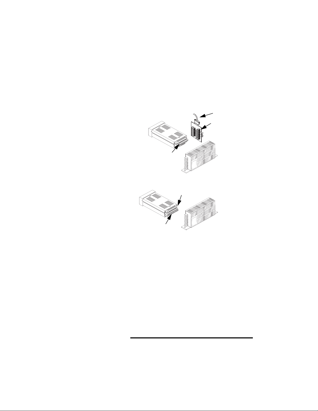
4. Remove the brackets and collar from the controller, if
they are already in place.
5. Slide the controller into the panel cutout.
6. Slide the mounting collar over the back of the controller,
making sure the mounting screw indentations face toward the back of the controller.
Bracket (top and bottom)
25
23
21
19
17
15
13
11
9
7
5
3
1
+
26
24
22
20
18
16
14
12
10
8
6
4
2
Bezel
Panel
Mounting Collar
Figure 2.4 Mounting Bracket
7. Loosen the mounting bracket screws enough to allow for
the mounting collar and panel thickness. Place each
mounting bracket into the mounting slots (head of the
screw facing the back of the controller). Push each bracket backward then to the side to secure it to the controller
case.
8. Make sure the case is seated properly. Tighten the installation screws firmly against the mounting collar to secure
the unit. Ensure that the end of the mounting screws fit
into the indentations on the mounting collar.
Doc. 0600-3120-2000 Watlow Anafaze 15
Page 34

Chapter 2: Installation Series D8 User’s Guide
Mounting the TB50
There are two ways to mount the TB50: Use the pre-installed
DIN rail mounting brackets or use the plastic standoffs.
TB50
Mounted
with Standoffs
TB50
Mounted to
DIN Rail
Figure 2.5 Mounting the TB50
DIN Rail Mounting
Snap the TB50 on to the DIN rail by placing the hook side on
the rail first, then pushing the snap latch side in place. See Figure 2.6.
Figure 2.6 TB50 Mounted on a DIN Rail (Front)
16 Watlow Anafaze Doc. 0600-3120-2000
Page 35

Series D8 User’s Guide Chapter 2: Installation
To remove the TB50 from the rail, use a flathead screw driver
to unsnap the bracket from the rail. See Figure 2.7.
Removal
Catch for
Screwdriver
DIN Rail
Snap Latch
Hook Side
Figure 2.7 TB50 Mounted on DIN Rail (Side)
Mounting with Standoffs
1. Remove the DIN rail mounting brackets from the TB50.
2. Choose a location with enough clearance to remove the
TB50, its SCSI cable and the controller itself.
3. Mark the four mounting holes.
4. Drill and tap four mounting holes for #6 (3.5 mm) screws
or bolts.
5. Mount the TB50 with four screws or bolts.
There are four smaller holes on the terminal board. Use these
holes to secure wiring to the terminal block with tie wraps.
0.7 in
(18 mm)
4 Holes for
#6 (3.5 mm)
Bolts or Screws
3.4 in
(86 mm)
0.2 in
(5 mm)
2.6 in
(66 mm)
SCSI Connector
0.2 in
0.2 in
(5 mm)
3.6 in
(91 mm)
(5 mm)
Figure 2.8 Mounting a TB50 with Standoffs
Doc. 0600-3120-2000 Watlow Anafaze 17
Page 36

Chapter 2: Installation Series D8 User’s Guide
Mounting the Power Supply
If you use your own power supply for the D8, refer to the power supply manufacturer’s instructions for mounting information. Choose a Class 2 power supply that supplies an isolated,
regulated 12 to 24 Vdc at 1 A.
Mounting Environment
Leave enough clearance around the power supply so that it
can be removed.
18 Watlow Anafaze Doc. 0600-3120-2000
Page 37

Series D8 User’s Guide Chapter 2: Installation
Mounting the Dual DAC or Serial DAC Module
This section describes how to mount the optional Dual DAC
and Serial DAC digital-to-analog converters.
Mounting of the Dual DAC and Serial DAC is essentially the
same, except that the dimensions differ.
Jumpers
The output signal range of the Dual DAC and Serial DAC
modules is configured with jumpers. See Configuring Dual
DAC Outputs on page 177 and Configuring Serial DAC Outputs on page 176 for information about setting these jumpers.
Mounting
1. Choose a location. The unit is designed for wall mounting. Install it as close to the controller as possible.
2. Mark and drill four holes for screw mounting. Holes accommodate #8 (3.5 mm) screws. See Figure 2.10 for
screw locations. Install the unit with the four screws.
Dual DAC
4 Holes for #8 (3.5 mm)
Screws or Bolts
3.62 in
(91 mm)
Electrical
Connectors
Electrical
Connectors
3.7 in
(94 mm)
4.40 in
(112 mm)
0.3 in
(8 mm)
3.00 in
(76 mm)
0.65 in
(17 mm)
1.75 in
(44 mm)
0.37 in
(9 mm)
4 Holes for #8 (3.5 mm)
Screws or Bolts
3.62 in
(91 mm)
Electrical
Connectors
Serial DAC
Electrical
Connectors
4.7 in
(119 mm)
5.40 in
(137 mm)
0.3 in
(8 mm)
3.00 in
(76 mm)
0.37 in
(9 mm)
0.65 in
(17 mm)
1.75 in
(44 mm)
Figure 2.10 Dual DAC and Serial DAC
Dimensions
Doc. 0600-3120-2000 Watlow Anafaze 19
Page 38

Chapter 2: Installation Series D8 User’s Guide
System Wiring
Successful installation and operation of the control system can
depend on placement of the components and on selection of
the proper cables, sensors and peripheral components.
Routing and shielding of sensor wires and proper grounding
of components can insure a robust control system. This section includes wiring recommendations, instructions for proper
grounding and noise suppression, and considerations for
avoiding ground loops.
WARNING! To reduce the risk of electrical shock, fire,
and equipment damage, follow all local and
national electrical codes. Correct wire sizes,
fuses and thermal breakers are essential for
safe operation of this equipment.
CAUTION! Do not wire bundles of low-voltage signal
Wiring Recommendations
and control circuits next to bundles of highvoltage ac wiring. High voltage may be inductively coupled onto the low-voltage circuits,
which may damage the controller or induce
noise and cause poor control.
Physically separate high-voltage circuits
from low-voltage circuits and from D8 hardware. If possible, install high-voltage ac power circuits in a separate panel.
Follow these guidelines for selecting wires and cables:
• Use stranded wire. (Solid wire can be used for fixed service; it makes intermittent connections when you move it
for maintenance.)
• Use 20 AWG (0.5 mm
Larger or smaller sizes may be difficult to install, may
break easily or may cause intermittent connections.
• Use shielded wire. The electrical shield protects the signals and the D8 from electrical noise. Connect one end of
the input and output wiring shield to earth ground.
• Use copper wire for all connections other than thermocouple sensor inputs.
2
) thermocouple extension wire.
20 Watlow Anafaze Doc. 0600-3120-2000
Page 39

Series D8 User’s Guide Chapter 2: Installation
Table 2.1 Cable Recommendations
Analog Inputs
RTD Inputs
Thermocouple Inputs
Control Outputs and
Digital I/O
Analog Outputs
Noise Suppression
Function Mfr. P/N
Belden 9154
Belden 8451
Belden 8772
Belden 9770
thermocouple
Ext. Wire
Belden 9539
Belden 9542
Ribbon Cable
Belden 9154
Belden 8451
The D8 outputs are typically used to drive solid state relays.
These relays may in turn operate more inductive types of
loads such as electromechanical relays, alarm horns and motor starters. Such devices may generate electromagnetic interference (EMI, or noise). If the controller is placed close to
sources of EMI, it may not function correctly. Below are some
tips on how to recognize and avoid problems with EMI.
No. of
Wires
2
2
3
3
2 20 0.5
9
20
50
2
2
AWG
20
22
20
22
24
24
22 to 14
20
22
2
mm
0.5
0.5
0.5
0.5
0.2
0.2
0.5 to 2.5
0.5
0.5
Symptoms of Noise
Avoiding Noise
For earth ground wire, use a large gauge and keep the length
as short as possible. Additional shielding may be achieved by
connecting a chassis ground strap from the panel to D8 case.
If your controller displays the following symptoms, suspect
noise:
• The display screen blanks out and then reenergizes as if
power had been turned off for a moment.
• The process variable value is incorrect on the controller
display.
Noise may also damage the digital output circuit such that the
digital outputs will not turn on. If the digital output circuit is
damaged, return the controller to Watlow Anafaze for repair.
To avoid or eliminate most RFI/EMI noise problems:
Doc. 0600-3120-2000 Watlow Anafaze 21
Page 40

Chapter 2: Installation Series D8 User’s Guide
• Connect the D8 case to earth ground. The D8 system includes noise suppression circuitry. This circuitry requires
proper grounding.
• Separate the 120 Vac and higher power leads from the
low-level input and output leads connected to the D8 series controller. Do not run the digital I/O or control output leads in bundles with ac wires.
• Where possible, use solid state relays (SSRs) instead of
electromechanical relays. If you must use electromechanical relays, avoid mounting them in the same panel
as the D8 series equipment.
• If you must use electromechanical relays and you must
place them in a panel with D8 series equipment, use a
0.01 microfarad capacitor rated at 1000 Vac (or higher)
in series with a 47
Ω, 0.5 watt resistor across the normal-
ly-open contacts of the relay load. This is known as a
snubber network and can reduce the amount of electrical
noise.
• You can use other voltage suppression devices, but they
are not usually required. For instance, you can place a
metal oxide varistor (MOV) rated at 130 Vac for 120 Vac
control circuits across the load, which limits the peak ac
voltage to about 180 Vac (Watlow Anafaze part number
26-130210-00). You can also place a transorb (back-toback zener diodes) across the digital output, which limits
the digital output voltage.
Additional Recommendations for a Noise Immune System
We strongly recommended the following:
• Isolate outputs through solid state relays, where possible.
• Isolate RTDs or “bridge” type inputs from ground.
• Isolate digital inputs from ground through solid state relays. If this is not possible, then make sure the digital input is the only connection to earth ground other than the
chassis ground.
Ground Loops
Ground loops occur when current passes from the process
through the controller to ground. This can cause instrument
errors or malfunctions.
A ground loop may follow one of these paths, among others:
• From one sensor to another.
• From a sensor to the dc power supply.
22 Watlow Anafaze Doc. 0600-3120-2000
Page 41

Series D8 User’s Guide Chapter 2: Installation
The best way to avoid ground loops is to minimize unnecessary connections to ground. Do not connect any of the follow-
ing terminals to earth ground:
• Power supply dc common
• TB1 terminals 9, 10, 19 (analog common)
• TB2 terminal 2 (dc power common)
Do not connect the analog common terminals to the other terminals listed above.
Power Connections
This section explains how to make power connections to the
D8 and the TB50.
DEVICENET
CONNECTOR
NETWORK LED
INDICATOR LIGHT
MODULE LED
INDICATOR LIGHT
Wiring the Power Supply
WARNING! Use a power supply with a Class 2 rating
Figure 2.11 D8 Series Controller with TB50
only. UL approval requires a Class 2 power
supply.
Connect power to the controller before any other connections,
This allows you to ensure that the controller is working before
any time is taken installing inputs and outputs.
Doc. 0600-3120-2000 Watlow Anafaze 23
Page 42

Chapter 2: Installation Series D8 User’s Guide
Table 2.2 Power Connections
Function Power Supply D8 TB2
DC Power
(Controller)
DC Common
Earth Ground Ground
+12 to 24 Vdc +
12 to 24 Vdc
Common
-
1. Connect the dc common terminal on the power supply to
the dc common (-) terminal on D8 TB2.
2. Connect the positive terminal on the power supply to the
dc positive (+) terminal on D8 TB2.
3. If using an isolated dc output or another power supply to
power the loads, connect the dc common of the supply
powering the loads to the dc common of the supply powering the controller.
4. Use the ground connector on TB2 for chassis ground.
This terminal is connected to the D8 chassis and must be
connected to earth ground.
5. Connect 120/240 Vac power to the power supply.
NOTE! Connect the dc common of the power supply
used for loads to the dc common of the supply powering the controller. If the supplies
are not referenced to one another, the controller’s outputs will not be able to switch the
loads.
NOTE! When making screw terminal connections,
tighten to 4.5 to 5.4 in.-lb. (0.5 to 0.6 Nm).
CAUTION! Without proper grounding, the D8 may not
operate properly or may be damaged.
24 Watlow Anafaze Doc. 0600-3120-2000
Page 43

Series D8 User’s Guide Chapter 2: Installation
CAUTION! To prevent damage from incorrect connec-
tions, do not turn on the heater power or other output power before testing the
connections as explained in Testing the System on page 26.
NOTE! Do not connect the controller’s dc common
(COM) to earth ground . Doing so will defeat
the noise protection circuitry, making measurements less stable.
solid-state relay (ssr)
+
-
ssr
+
ssr
-
+
-
+5V
5V COM
+15V
15V COM
-15V
Ground
AC Line
AC Neutral
green
black
white
add jumper
D8
Controller
L1
L2
V+
common
ground
digital-to-analog
converter
120/240VÅ (ac)
ssr
1 2 3 4
Serial
+
-
Figure 2.12 Power Connections with the D8
Power Supply
Connecting the TB50 to the D8
1. Connect the SCSI cable to the controller.
2. Connect the SCSI cable to the TB50.
Doc. 0600-3120-2000 Watlow Anafaze 25
Page 44

Chapter 2: Installation Series D8 User’s Guide
Testing the System
This section explains how to test the controller after installation and prior to making field wiring connections.
TB50 or TB18 Test
Use this procedure to verify that the TB50 or TB18 is properly
connected and supplied with power:
1. Turn on power to the D8. The display should first show
Calculating checksum, and then show the single-loop
display. If you do not see these displays, disconnect power and check wiring and power supply output.
2. Measure the +5 Vdc supply at the TB50 or TB18:
a) Connect the voltmeter’s common lead to TB50 ter-
minal 3 or TB18 terminal 2.
b) Connect the voltmeter’s positive lead to TB50 or
TB18 terminal 1. The voltage should be +4.75 to
+5.25 Vdc.
Digital Output Test
Use this procedure to test the controller outputs before loads
are connected. If using it at another time for troubleshooting,
disconnect loads from outputs before testing.
1. Connect a 500
TB18 terminal 1 and a digital output terminal. See
Table 2.6 on page 36 for TB18 connections or Table 2.7
on page 37 for TB 50 connections.
2. Connect the voltmeter’s positive lead to terminal 1 on the
TB50 or TB18.
3. Connect the voltmeter’s common lead to the digital output terminal.
4. Use the digital output test in the I/O tests menu to turn the
digital output on and off (see Test Digital Output 1 to 20
on page 153). When the output is off, the output voltage
should be less than 1 V. When the output is on, the output
voltage should be between 4.75 and 5.25 V.
Ω to 100 k Ω resistor between TB50 or
NOTE! By default, heat outputs are enabled. Only
disabled outputs may be turned on using the
manual I/O test. To test heat outputs, set the
corresponding loop to manual mode 100 percent output. See Changing the Control Mode
and Output Power on page 85.
26 Watlow Anafaze Doc. 0600-3120-2000
Page 45

Series D8 User’s Guide Chapter 2: Installation
Digital Input Test
Use the following procedure to test digital inputs before connecting to field devices:
1. Disconnect any system wiring from the input to be tested.
2. Go to the Digital inputs test in the I/O tests menu. This
test shows whether the digital inputs are off (open) or on
(closed).
3. Attach a wire to the terminal of the digital input you want
to test. See Table 2.6 on page 36 for TB 18 connections
or Table 2.7 on page 37 for TB50 connections.
a) When the wire is connected only to the digital input
terminal, the digital input test should show that the
input is off (open).
b) When you connect the other end of the wire to the
controller common (TB50 terminal 3 or TB18 terminal 2), the digital input test should show that the
input is on (closed).
Sensor Wiring
CAUTION! Never run input leads in bundles with high
This section describes how to properly connect thermocouples, RTDs, current and voltage inputs to the controller. The
controller can accept any mix of available input types. Some
input types require that special scaling resistors be installed
(generally done by Watlow Anafaze before the controller is
delivered).
All inputs are installed at the “CH” input connectors (TB1) at
the back of the controller. The illustrations below show the
connector locations for all D8 series controllers.
power wires or near other sources of EMI.
This could inductively couple voltage onto
the input leads and damage the controller, or
could induce noise and cause poor measurement and control.
Doc. 0600-3120-2000 Watlow Anafaze 27
Page 46

Chapter 2: Installation Series D8 User’s Guide
Table 2.3 TB1 Connections
Terminal Number Label Function
1 CH 1 IN+ Channel 1 positive input
2 CH 1 IN- Channel 1 negative input
3 CH 2 IN+ Channel 2 positive input
4 CH 2 IN- Channel 2 negative input
5 CH 3 IN+ Channel 3 positive input
6 CH 3 IN- Channel 3 negative input
7 CH 4 IN+ Channel 4 positive input
8 CH 4 IN- Channel 4 negative input
9 Com Analog Common
10 Com Analog Common
11 CH 5 IN+
12 CH 5 IN-
13 CH 6 IN+
14 CH 6 IN-
15 CH 7 IN+
16 CH 7 IN-
17 CH 8 IN+
18 CH 8 IN-
Channel 5 positive input
Channel 5 negative input
Channel 6 positive input
Channel 6 negative input
Channel 7 positive input
Channel 7 negative input
Channel 8 positive input
Channel 8 negative input
1
1
1
1
1
1
1
1
19 Com Analog Common
NOTE!
1
Terminals 11 to 18 are not used with a 4-channel controller.
Input Wiring Recommendations
Use multicolored stranded shielded cable for analog inputs.
Watlow Anafaze recommends that you use 20 AWG wire (0.5
2
). If the sensor manufacturer requires it, you can also use
mm
24 or 22 AWG wiring (0.2 mm
twisted pair; some require a three-wire input.
The controller accepts the following inputs without any special scaling resistors:
• J, K, T, S, R, B and E thermocouples.
• Process inputs with ranges between -10 and 60 mV.
To avoid thermocouple open alarms on unused inputs, either
set the Input type parameter to skip or jumper the input.
28 Watlow Anafaze Doc. 0600-3120-2000
2
). Most inputs use a shielded
Page 47

Series D8 User’s Guide Chapter 2: Installation
Thermocouple Connections
Connect the positive lead of the thermocouple to the IN+ terminal for one of the loops, and connect the negative lead to the
corresponding IN- terminal.
2
Use 18 or 20 AWG (0.5 or 0.75 mm
puts. Most thermocouple wire is solid, unshielded wire. When
using shielded wire, ground one end only.
) for all thermocouple in-
CH IN+
CH IN-
White
Red
Shield (if present)
Earth Ground at Process End
Type J thermocouple
Figure 2.13 Thermocouple Connections
CAUTION! Ground loops and common mode noise can
damage the controller or disrupt measurements. To minimize ground loops and common mode noise:
• Do not mix grounded and ungrounded ther-
mocouples. If any thermocouple connected
to the controller is of grounded construction,
all thermocouples should be of grounded
construction and each should be connected
to ground at the process end.
• Connect the earth ground terminal on TB2
to a good earth ground, but do not connect
the analog common to earth ground. The D8
uses a floating analog common for sensor
measurements. The noise protection circuits
on the sensor inputs function correctly only
if the controller is correctly installed. See
Ground Loops on page 22.
Doc. 0600-3120-2000 Watlow Anafaze 29
Page 48

Chapter 2: Installation Series D8 User’s Guide
RTD Input Connections
RTD inputs require accessory resistors. Watlow Anafaze recommends that you use a 100
Ω, three-wire platinum RTD to
prevent reading errors due to cable resistance. If you use a
two-wire RTD, jumper the negative input to common. If you
must use a four-wire RTD, leave the fourth wire unconnected.
IN +
CH
100 Ω RTD
IN -
CH
Com
Figure 2.14 RTD Connections
Voltage Input Connections
Voltage inputs with ranges greater than -10 to 60 mV require
accessory resistors. Special input resistors installed at Watlow
Anafaze divide analog input voltages such that the controller
sees a -10 to 60 mV signal on the loop.
Current Input Connections
CH IN+
CH IN-
Device with
Voltage
Output
Figure 2.15 Voltage Signal Connections
Current inputs require accessory resistors. Special input resistors installed at Watlow Anafaze for analog current signals are
such that the controller sees a -10 to 60 mV signal across its
inputs for the loop.
CH IN+
CH IN-
Device with
Current
Output
Figure 2.16 Current Signal Connections
30 Watlow Anafaze Doc. 0600-3120-2000
Page 49

Series D8 User’s Guide Chapter 2: Installation
Wiring Control and Digital I/O
This section describes how to wire and configure the control
outputs for the D8 series controller. The D8 provides dual
control outputs for each loop. These outputs can be enabled or
disabled, and are connected through a TB50 or TB18.
NOTE! Control outputs are connected to controller
common when the control output is on. If you
connect external devices that may have a low
side at a voltage other than controller
ground, you may create ground loops. To
prevent ground loops, use isolated solid
state relays and isolate the control device inputs.
Output Wiring Recommendations
When wiring output devices, use multicolored, stranded,
shielded cable for analog outputs and digital outputs connected to panel-mounted solid state relays.
Cable Tie Wraps
Digital Outputs
• Analog outputs usually use a twisted pair.
• Digital outputs usually have 9 to 20 conductors, depending on wiring technique.
After you wire outputs to the TB50, install the cable tie wraps
to reduce strain on the connectors. Each row of terminals has
a cable tie wrap hole at one end. Thread the cable tie wrap
through the cable tie wrap hole. Then, wrap the cable tie wrap
around the wires attached to that terminal block.
The D8 provides dual control outputs for up to eight loops. By
default, heat outputs are enabled and cool outputs are disabled. If the heat or cool output is disabled for a loop, then the
output is available for alarms or programmable logic. The
CPU watchdog timer output can be used to monitor the state
of the controller; see CPU Watchdog Timer on page 34.
Doc. 0600-3120-2000 Watlow Anafaze 31
Page 50

Chapter 2: Installation Series D8 User’s Guide
Table 2.4 Digital Output States and Values
Stored in the Controller
State
Off 0 Open circuit
On 1 Sinking current to controller common
1
Read and write these values through communications.
Value
1
Description
All digital outputs sink current to controller common when
on. The load may powered by the 5 Vdc supplied by the controller at the TB50, or by an external power supply. When using an external power supply, bear in mind:
• The D8 power supply available from Watlow Anafaze
includes a 5 Vdc supply. When using it to supply output
loads, connect the 5 Vdc common to the 15 Vdc common
at the power supply.
• Do not exceed +24 volts.
• If you connect the external load to earth ground, or if you
cannot connect it as shown in Figure 2.17, then use a solid state relay.
The outputs conduct current when they are on. The maximum
current sink capability is 60 mA at 24 Vdc. The outputs cannot
“source” current to a load.
Using Internal Power Supply
TB50 or TB18
+5 Vdc
Digital Output 1
Digital Output 2
Figure 2.17 Digital Output Wiring
Loads
Using External Power Supply
External
Power
Supply
to earth ground or
equipment ground
TB50 or TB18
Control Common
Digital Output 1
Digital Output 2
+
-
Do not connect
Loads
32 Watlow Anafaze Doc. 0600-3120-2000
Page 51

Series D8 User’s Guide Chapter 2: Installation
Configuring Outputs
As you choose outputs for control and alarms, bear in mind
the following points:
• You can enable or disable the control outputs. By default,
heat outputs are enabled and cool outputs are disabled.
• You can program each control output individually for on/
off, time proportioning, distributed zero-crossing or Serial DAC control.
• You can individually program each control output for direct or reverse action.
• Alarm outputs other than the global alarm are non-latching. See Global Alarm on page 97.
• Alarms can be suppressed during process start up and for
preprogrammed durations. See Power Up Alarm Delay
on page 128.
• Alarm outputs can be configured, as a group, to sink to
output during an alarm or stop current flow during an
alarm. See Digital Output Alarm Polarity on page 129.
Control and Alarm Output Connections
Typically control and alarm outputs use external opticallyisolated solid state relays (SSRs). SSRs accept a 3 to 32 Vdc
input for control, and some can switch up to 100 Amps at 480
Vac. For larger currents, use silicon control rectifier (SCR)
power controllers up to 1000 Amps at 120 to 600 Vac. You
can also use SCRs and a Serial DAC for phase-angle fired
control.
The control and alarm outputs are open collector outputs referenced in the D8’s common. Each output sinks up to 60
mAdc to the controller common when on.
NOTE! Control outputs are sink outputs. They sink
current when the output is on. Connect them
to the negative side of solid state relays.
Figure 2.18 shows sample heat, cool and alarm output connections.
TB50 or TB18
Heat Output
Cool Output
Alarm Output
+5 Vdc
SSR SSR SSR
+-
+-
+-
Figure 2.18 Sample Heat, Cool and Alarm
Output Connections
Doc. 0600-3120-2000 Watlow Anafaze 33
Page 52

Chapter 2: Installation Series D8 User’s Guide
CPU Watchdog Timer
TB50 or TB18
Heat Output
Cool Output
Alarm Output
Common
SSR
+-
- PS +
SSR
SSR
+-
+-
Figure 2.19 Output Connections Using
External Power Supply
The CPU watchdog timer constantly monitors the microprocessor. It is a sink output located on TB50 terminal 6 or TB18
terminal 3. The output can be connected to an external circuit
or device to monitor whether the controller is powered and operational. The output is on (low) when the microprocessor is
operating; when it stops operating, the output goes off (high).
Figure 2.20 and Figure 2.21 show the recommended circuit
for the watchdog timer output for the TB50 and the TB18.
TB50
+ 5 Vdc
(Terminal 1)
Watchdog Timer
(Terminal 6)
+
SSR
-
Figure 2.20 TB50 Watchdog Timer Output
TB18
+ 5 Vdc
(Terminal 1)
Watchdog Timer
(Terminal 3)
+
SSR
-
Figure 2.21 TB18 Watchdog Timer Output
34 Watlow Anafaze Doc. 0600-3120-2000
Page 53

Series D8 User’s Guide Chapter 2: Installation
Digital Inputs
All digital inputs are transistor-transistor logic (TTL) level inputs referenced to controller common and the internal +5 V
power supply of the D8.
When an input is connected to the controller common, the input is considered on. Otherwise, the input is considered off.
Most features that use the digital inputs can be user-configured to activate when an input is either on or off.
External Switching Device
In the off state, internal 4.7 k
Ω resistors pull the digital inputs
high to 5 Vdc with respect to the controller common.
Table 2.5 Digital Input States and Values
Stored in the Controller
State
Off 0 Open circuit
On 1
1
Read and write these values through communications.
To ensure that the inputs are reliably switched, use a switching
device with the appropriate impedances in the on and off
states and do not connect the inputs to external power sources.
When open, the switching device must provide an impedance
of at least 14 k
than 3.7 Vdc. When closed, the switch must provide not more
than 1.7 k
Ω impedance to ensure the voltage drops below 1.3
Vdc.
1
Value
Digital input connected to controller
common
Ω to ensure that the voltage will rise to greater
Description
To install a switch as a digital input, connect one lead to the
common terminal on the TB50 (terminals 3 and 4) or TB18
(terminal 2). Connect the other lead to the desired digital input
terminal on the TB50 (terminals 43 to 50) or TB18 (terminals
16 to 18).
TB50
Input
Control Com
External
Switching
Device
Figure 2.22 Wiring Digital Inputs
Doc. 0600-3120-2000 Watlow Anafaze 35
Page 54

Chapter 2: Installation Series D8 User’s Guide
Functions Activated by Digital Inputs
Use digital inputs to activate the following functions:
• Load a job that is stored in controller memory. See BCD
Job Load on page 126.
• Change all loops to manual mode at specified output levels. See Mode Override on page 127.
• Enable thermocouple short detection. See Thermocouple
Short Alarm on page 129.
• Restore automatic control after a failed sensor has been
repaired. See Restore Automatic Mode on page 138.
TB18 Connections
Table 2.6 TB18 Connections
Control Output
1
Terminal Function D84 _ - _ _ _ _ - _ _ _ _ D88 _ - _ _ _ _ - _ _ _ _
1 +5 Vdc
2 CTRL COM
3 Watchdog timer
4 Global alarm
5 Output 1 Loop 1 heat Loop 1 heat
6 Output 2 Loop 2 heat Loop 2 heat
7 Output 3 Loop 3 heat Loop 3 heat
8 Output 4 Loop 4 heat Loop 4 heat
9 Output 5 Loop 1 cool Loop 5 heat
10 Output 6 Loop 2 cool Loop 6 heat
11 Output 7 Loop 3 cool Loop 7 heat
12 Output 8 Loop 4 cool Loop 8 heat
13 Output 9 Loop 1 cool
14 Output 10 Loop 2 cool
15
Output 18
2
Serial DAC clock Serial DAC clock
16 Input 1
17 Input 2
18 Input 3
1
The indicated outputs are dedicated for control when enabled in the
loop setup. If one or both of the outputs are disabled for a loop, then the
corresponding digital outputs become available for alarms.
2
If you install a Watlow Anafaze Serial DAC, the D8 series controller
uses digital output 18 (terminal 15) for a clock line. You cannot use output 18 for anything else if a Serial DAC is installed.
36 Watlow Anafaze Doc. 0600-3120-2000
Page 55

Series D8 User’s Guide Chapter 2: Installation
TB50 Connections
Table 2.7 TB50 Connections
1
Ter-
minal
Function D88 D84
Ter-
minal
Control Output
Function D88 D84
1 +5 Vdc 2 +5 Vdc
3 CTRL COM 4 CTRL COM
5 Not used 6 Watchdog
Timer
7 Not used 8 Global Alarm
9 Output 1 Loop 1 heat Loop 1 heat 10
Not used
11 Output 2 Loop 2 heat Loop 2 heat 12 Not used
13 Output 3 Loop 3 heat Loop 3 heat 14 Not used
15 Output 4 Loop 4 heat Loop 4 heat 16 Not used
17 Output 5 Loop 5 heat Loop 1 cool 18 Not used
19 Output 6 Loop 6 heat Loop 2 cool 20 Not used
21 Output 7 Loop 7 heat Loop 3 cool 22 Not used
23 Output 8 Loop 8 heat Loop 4 cool 24 Not used
25 Output 9 Loop 1 cool 26 Not used
27 Output 10 Loop 2 cool 28 Not used
29 Output 11 Loop 3 cool 30 Not used
31 Output 12 Loop 4 cool 32 Not used
33 Output 13 Loop 5 cool 34 Not used
35 Output 14 Loop 6 cool 36 Not used
37 Output 15 Loop 7 cool 38 Not used
39 Output 16 Loop 8 cool 40 Not used
41 Output 17 42
Output 18
43 Input 1 44 Input 2
45 Input 3 46 Input 4
47 Input 5 48 Input 6
49 Input 7 50 Input 8
1
The indicated outputs are dedicated for control when enabled in the
loop setup. If one or both of a loop’s outputs are disabled, the corresponding digital outputs become available for alarms or programmable
logic.
2
If you install a Watlow Anafaze Serial DAC, the D8 uses digital output
18 (terminal 42) for a clock line. You cannot use output 18 for anything
else if a Serial DAC is installed.
2
Control Output
Serial
DAC clock
1
Doc. 0600-3120-2000 Watlow Anafaze 37
Page 56

Chapter 2: Installation Series D8 User’s Guide
Analog Outputs
Analog outputs can be provided by using a Dual DAC or Serial DAC module to convert the open collector outputs from
the controller. Use multicolored stranded shielded cable for
analog outputs. Analog outputs generally use a twisted pair
wiring. The following sections describe how to connect the
Dual DAC and Serial DAC modules to power the controller
outputs and the load.
Wiring the Dual DAC
A Dual DAC module includes two identical circuits. Each can
convert a distributed zero cross (DZC) signal from the controller to a voltage or current signal. Watlow Anafaze strong-
ly recommends using a power supply separate from the
controller supply to power the Dual DAC. Using a separate
power supply isolates the controller’s digital logic circuits and
analog measurement circuits from the frequently noisy devices that take the analog signal from the Dual DAC.
Several Dual DAC modules may be powered by one power
supply. Consult the Specifications chapter for the Dual
DAC’s power requirements. Also note in the specifications
that the Dual DAC does not carry the same industry approvals
as the Serial DAC.
TB50 or TB18
+5V 1
Control Output
mA Load
+
-
Dual DAC
+5V CTRL Supply
1
DZC CTRL PID Output
2
+12/24 Vdc External
3
Power Supply
+Vdc Load Connection
4
-mAdc Load Connection
5
-External Power
6
Supply/ Vdc Load
Connection
+ -
12 to 24 Vdc Power Supply
Figure 2.23 Dual DAC with Current Output
38 Watlow Anafaze Doc. 0600-3120-2000
Page 57

Series D8 User’s Guide Chapter 2: Installation
Wiring the Serial DAC
TB50 or TB18
+5V 1
PID Loop Output
Vdc Load
+
-
Dual DAC
+5V CTRL Supply
1
DZC CTRL PID Output
2
+12/24 Vdc External
3
Power Supply
+Vdc Load Connection
4
-mAdc Load Connection
5
-External Power
6
Supply/ Vdc Load
Connection
+ -
12 to 24 Vdc Power Supply
Figure 2.24 Dual DAC with Voltage Output
The Serial DAC provides a robust analog output signal. The
module converts the proprietary Serial DAC signal from the
controller’s open collector output in conjunction with the
clock signal to an analog current or voltage. See Figure 2.25
for wiring. The Serial DAC is user-configurable for voltage or
current output through firmware configuration. See Configuring Serial DAC Outputs on page 176.
The Serial DAC optically isolates the controller’s control output from the load. When a single Serial DAC is used, it may
be powered by the 5 Vdc found on the TB50 or by an external
power supply referenced to the controller’s power supply.
When using multiple Serial DACs, the controller cannot provide sufficient current; use the 5 Vdc output from the D8 power supply.
Doc. 0600-3120-2000 Watlow Anafaze 39
Page 58

Chapter 2: Installation Series D8 User’s Guide
Controller
Power Supply
5 V Common
15 V Common
TB50 or TB18
Serial DAC Clock
Control Output
Daisy chain up to
16 Serial DACs
+5 V
Serial DAC
1
2
3
4
5
6
Figure 2.25 Single/Multiple Serial DACs
Connecting the D8 to a DeviceNet Network
+5V In
COM In
CLK In
Data In
+ Out
- Out
Load
-
+
Connector Type
Connect the D8 to the DeviceNet network using a female,
sealed, micro-style, quick disconnect connector with five conductors. The DeviceNet connector is in the back of the controller.
J4
DeviceNet
Connector
Network LED
Indicator Light
Module LED
Indicator Light
Figure 2.26 DeviceNet Connector
40 Watlow Anafaze Doc. 0600-3120-2000
Page 59

Series D8 User’s Guide Chapter 2: Installation
J4
DeviceNet
Connector
Network LED
Indicator Light
Module LED
Indicator Light
Figure 2.27 DeviceNet Connector
Pinout
2
3
4
Figure 2.28 Pinout
Table 2.8 DeviceNet Connector
Pin Signal Function
1 Shield Shield interconnect
2 V+ DeviceNet power
3 V- DeviceNet power return
1
5
4 CAN+ Positive side of the DeviceNet bus
5 CAN- Negative side of DeviceNet bus
Doc. 0600-3120-2000 Watlow Anafaze 41
Page 60

Chapter 2: Installation Series D8 User’s Guide
Network Length
The network speed is limited by the end-to-end network distance. The longer the network, the slower the baud rate setting
must be. See Table 2.9
Table 2.9 Maximum Network Speed
Distance Baud Rate
100 m (328 ft) 500 Kbps
250 m (820 ft) 250 Kbps
500 m (1,640 ft) 125 Kbps
Baud Rate (Data Rate)
DeviceNet communications can use three different baud rates
(data rates) 125k, 250k, and 500k baud. When the switch is set
to the PGM position, the unit's baud rate is determined by a
software setting. If the switch is set to PGM you must set the
data rate using the controller’s front panel or network-configuration software. As long as the switch is set to PGM, the controller will always come back up on the network with the last
software-configured baud rate stored in the controller's memory.
NOTE! When changing the baud rate via the soft-
Node Address (MAC ID)
As an example, assume the controller's baud rate switch is set
to PGM, and it is programmed at 500k baud. Assume too, that
the DeviceNet network experiences a power loss. When power is restored, the controller will come back up with a baud
rate of 500k baud. If on the other hand, the baud rate switch
was changed to 250k baud before the network power had been
restored, the controller will attempt to come back on the network at 250k baud.
ware or by manually changing the switch position, you will need to cycle power on the
network for the change to take effect.
Valid node addresses on a DeviceNet network range from 0 to
63 decimal. When the switch is set to the PGM position, the
unit's node address is determined by a software setting. If the
switch is set to “PGM” you must set the node address using
the controller’s front panel or network-configuration software. As long as the switch setting remains set for software
42 Watlow Anafaze Doc. 0600-3120-2000
Page 61

Series D8 User’s Guide Chapter 2: Installation
selection, the controller will always come back up on the network with the last software configured node address stored in
the controller's memory.
Set the controller’s MAC ID with the two rotary switches on
the side of the case. Set the most significant digit (MSD) with
the left switch and the least significant digit (LSD) with the
right switch. For example, to set the address to 23, set the
MSD to 2 and the LSD to 3.
NOTE! If the node address is changed with the
switch, the D8 controller’s power must be cycled before the change takes effect. If the
node address is changed using software, the
change takes effect immediately.
Status Indicators
Figure 2.29 D8 Side with Rotary Switches
The D8 controller has two indicator lights on the back, one labeled “NET” (Network) and the other labeled “MOD” (Module). On power-up the controller performs a self-test. The
indicator light identified as "MOD" displays the result of this
test as either pass (green) or fail (red). Also, under normal operation the indicator lights indicate the health of the module
and the network. In the event that an indicator light should go
from green to red either on power up or afterwards, consult tables Table 2.10 and Table 2.11 below for basic troubleshooting.
Doc. 0600-3120-2000 Watlow Anafaze 43
Page 62

Chapter 2: Installation Series D8 User’s Guide
Table 2.10 Module Status Indicator Light
Indicator Light Description
Off No power is applied to the device.
Flashing Green-Red The device is performing a Self-Test.
Green The device is operating normally
Red The device has detected an unrecoverable fault.
Table 2.11 Network Status Indicator Light
Indicator Light Description
The device is not online.
Off
Green
The device has not completed the duplicate MAC ID test yet.
The device may not be powered. Look at Table 2.10 ,Module Status
Indicator Light.
The device is online and has connections in the established state.
For a Group 2 Only device it means that the device is allocated to a
Master.
Failed communication device.
Red
Flashing Green
Flashing Red A poll connection has timed out.
The device has detected an error that has rendered it incapable of
communicating on the network (Duplicate MAC ID, or Bus-off).
The device is online, but no connection has been allocated or an
explicit connection has timed out.
44 Watlow Anafaze Doc. 0600-3120-2000
Page 63

Communicating by DeviceNet
This chapter explains how to add a D8 series controller to a
DeviceNet network and how to access and manipulate the
controller's data over a network using a Programmable Logic
Controller or other device with a DeviceNet scanner. The
chapter also includes descriptions of the D8's objects and attributes that are accessible via the DeviceNet protocol.
Accessing Data with a DeviceNet Master
Figure 3.12 to Figure 3.15 starting on page 65 illustrate the inputs and outputs in the D8 controller's polled I/O messages.
These messages are typically used to get the controller's data
in and out of a master on a DeviceNet network. To use this
data in a Programmable Logic Controller (PLC) these parameters must be mapped through the master (scanner) to memory
locations accessible to the PLC or other control devices.
3
When configuring the number of input bytes, it is important to
note that the first input byte, the Exception Status Byte is not
currently used. When configuring the D8 with DeviceNet network software such as RSNetWorx™, you must offset the
polled input data by one byte. See the example in Mapping
Polled I/O Data on page 50.
Software
More than one software package is available to configure devices such as the D8 on a DeviceNet network. This chapter
provides step-by-step examples of configuring the D8 controller using Rockwell Software’s RSNetWorx. The methodology used to accomplish this task will be different in other
software, but the key steps and the end result, a valid stream
Doc. 0600-3120-2000 Watlow Anafaze 45
Page 64

Chapter 3: Communicating by DeviceNet Series D8 User’s Guide
of data from the D8 to the PLC or other device, will be the
same.
About The Electronic Data Sheet (EDS)
Most, if not all, vendors supply an EDS file with their DeviceNet products. The EDS file allows for faster and easier
configuration with the network software, but it is not required
to make the device work. The examples cover commissioning
the D8 on a network both with and without the EDS file. EDS
files for the D8 are available on the Watlow web site and upon
request from Watlow technical support.
NOTE! There are several versions of the EDS file.
You must use the correct file for the number
of loops in the controller (D84, 4-loop, or D88,
8-loop) and the controller firmware revision.
This information is included in the file description on Watlow's web site.
Configuring a D8 Using RSNetWorx
Complete the following steps prior to configuring the DeviceNet network software:
• The physical layer of the DeviceNet network is built.
• At least the D8 controller, a DeviceNet master, and a
computer interface are connected to the network.
• Each device has a unique node addresses and the same
baud rate setting.
Once all the devices are connected and power is applied to the
network:
1. With RSLinx™ select and configure the appropriate
communications driver for your hardware.
2. Open RSNetWorx and go online.
46 Watlow Anafaze Doc. 0600-3120-2000
Page 65

Series D8 User’s Guide Chapter 3: Communicating by DeviceNet
Figure 3.1 RSNetWorx On-line with
Figure 3.1 shows node address 1 with a question mark on its
icon, indicating that this device has not yet been registered in
RSNetWorx. At this point the user may register an existing
EDS file or create one. Both options are addressed in the following sections.
Registering the D8 without an EDS File
This section assumes the user does not have an EDS file from
Watlow for the D8 controller but needs to get the unit up and
running anyway.
To register the device without the Watlow EDS file:
1. Double-click the device with a question mark.
2. Proceed through the prompts to create an EDS file.
3. Select the polled method (Master/Slave) and then enter
the number of input and output bytes. See Table 3.1.
Found Devices
Doc. 0600-3120-2000 Watlow Anafaze 47
Page 66

Chapter 3: Communicating by DeviceNet Series D8 User’s Guide
Table 3.1 Number of Bytes
Controller Input Bytes Output Bytes
D84 (4-loop) 41 12
D88 (8-loop) 81 24
Figure 3.2 The D8 Registered in RSNetWorx
Registering the D8 with the Watlow EDS File
There are important differences between the results of registering the D8 controller with and without the Watlow-supplied EDS file, though these differences are not readily visible
in Figure 3.2.
Double-clicking node address 1 (D8 controller) in the RSNetWorx graph of the network opens the dialog box shown at the
left in Figure 3.3. When the controller is registered with the
Watlow EDS, the same dialog box has an additional tab labeled Parameters as shown at the right in the figure.
48 Watlow Anafaze Doc. 0600-3120-2000
Page 67

Series D8 User’s Guide Chapter 3: Communicating by DeviceNet
A. Registered without the Watlow EDS B. Registered with the Watlow EDS
Figure 3.3 D8 Properties in RSNetWorx
The Parameters tab provides access to all of the D8 controller's parameters. See Figure 3.4. Some of these parameters
have read-only access and some have read-and-write access.
This tab can be a valuable tool for configuring the D8. Without the Watlow EDS file all configuration must be done
through the front panel of the controller or via explicit messages initiated through a PLC or other device passed through
a scanner (DeviceNet master).
Doc. 0600-3120-2000 Watlow Anafaze 49
Page 68

Chapter 3: Communicating by DeviceNet Series D8 User’s Guide
Figure 3.4 Parameters Tab
Mapping Polled I/O Data
Once the D8 controller is registered, the master must be configured to communicate with it. Once the master is configured
it is possible to map the polled I/O data from the D8 to the
PLC. The next sections address these steps.
Adding the D8 to the Master's Scanlist
This section describes configuring the DeviceNet scanner so
that it will copy data between the scanner's memory and the
D8 controller.
To add the D8 controller to the scanlist:
1. Double-click the 1747-SDN scanner (see Figure 3.2 on
page 48) to open its properties dialog box. The properties
dialog lists the Available Devices and displays the scanner's Scanlist (see Figure 3.5 on page 51). The Scanlist
shows the devices that are mapped into the scanner's
memory, the Available Devices list displays the devices
that are on the network.
2. Uncheck the Automap on Add option. (When checked the
software automatically assigns addresses to data from the
50 Watlow Anafaze Doc. 0600-3120-2000
Page 69

Series D8 User’s Guide Chapter 3: Communicating by DeviceNet
device starting at the next available byte in the PLC
memory. When not checked the user controls how the
bytes are arranged.)
3. Select 01 Watlow D84/D88 by clicking it in the Available
Devices list.
4. Click the right-arrow button to put the D8 on the Scanlist.
Assigning PLC Addresses
Figure 3.5 Adding the D8 to the Scanlist
Once the device has been added to the Scanlist, it is possible
to map the polled bytes to any available contiguous memory
location for both inputs and outputs.
The Allen-Bradley 1747-SDN scanner module in this example consumes the first 32 words of the input and output files
corresponding to the slot in which it is inserted. For example,
when the module is inserted in slot 3 of the PLC, the scanner
uses addresses in the input file I:3.0 through I:3.31. This provides only 32 words of memory. Because the D88 controller
supplies 81 bytes or 40.5 words of input, it is necessary to map
the incoming polled data to the scanner's M1 file instead.
The following procedure maps the D88's input bytes to the
scanner's M1 file. Actually only 40 words or 80 bytes of input
data will be mapped because the Exception Status Byte, which
is currently unused, is excluded.
Doc. 0600-3120-2000 Watlow Anafaze 51
Page 70

Chapter 3: Communicating by DeviceNet Series D8 User’s Guide
The Node list in Figure 3.6 indicates that the scanner will
communicate with the D8 via Polled messages. The scanner
expects to find 81 bytes, but no data is currently mapped. The
figure also shows four other devices on the network and their
corresponding communications and data mapping configurations.
Figure 3.6 Scanner Input Properties
To map the D8's data:
1. Select the D8 by clicking 01, Watlow D84/D88 in the
Node list on the Input tab.
2. Click the Advanced button to open the Advanced Map-
ping dialog box. See Figure 3.7 on page 53.
3. In the Map From group, for Message, select Polled, and
set Byte to 1. (This excludes the first byte.)
4. In the Map To group, for Memory, select M File.
5. Set Bit Length to 640. (80 bytes times 8 bits per byte is
640 bits, the Exception Status Byte is excluded.)
6. Click Apply Mapping.
52 Watlow Anafaze Doc. 0600-3120-2000
Page 71

Series D8 User’s Guide Chapter 3: Communicating by DeviceNet
Figure 3.7 Advanced Mapping Dialog Box
Sample Ladder Logic
Accessing Polled I/O Data
The D8's polled input data is now mapped to the scanner's M1
file.
The scanner's M0 file may similarly be used to map the DeviceNet output data. The output data is easier to map because
there is no Exception Status Byte to omit. See Poll Connection
on page 64 for information on the output data.
The following sections give examples of using information
from the polled I/O and using explicit messages to read and
write data between the D8 controller and a PLC.
For a better understanding of the ladder logic examples in this
section, refer to Figure 3.14 and Figure 3.15 starting on page
65. These figures illustrate the polled input and output messages. Because the first byte of the input data, the Exception
Status Byte was excluded, the first word mapped is loop 1's
Process Variable, and it is stored in the scanner's memory at
M1:1.0. The Process Variables for subsequent loops are in the
next seven memory locations (M1:1.1 to M1:1.7).
All ladder logic examples that follow were made using an
Allen-Bradley SLC 5/04. Although there are different instruc-
Doc. 0600-3120-2000 Watlow Anafaze 53
Page 72

Chapter 3: Communicating by DeviceNet Series D8 User’s Guide
tions from one PLC manufacturer to another, the same concepts apply.
NOTE! The contents of the scanner's M1 file cannot
be monitored directly in RSLogix™, the logic-programming environment used in the following examples. For ease of demonstration
and troubleshooting, the relevant registers
are copied from the scanner's M1 file to the
PLC's N14 file.
Figure 3.8 Using Scanned Data in Logic
For programming convenience the ladder program in
Figure 3.8 copies the portion of the scanner's memory to
which the D8's inputs are mapped into an integer file, N14:0.
This information is automatically polled so it does not require
special communication instructions to update values between
the D8 and the PLC. During every PLC scan the DeviceNet
scanner is queried for the latest values stored in its memory.
The D8 controller stores and communicates Process Variables
and other parameters in tenths of a degree (see Decimal Placement for Numeric Values on page 59). In the logic a divide
function scales the scanned value into whole degrees. The
DIV function block divides the value in N14:0 (923) by 10
and places the temperature (92° F) into N14:43. This value can
be used elsewhere in logic, and the programmer will know
that the value is in degrees.
54 Watlow Anafaze Doc. 0600-3120-2000
Page 73

Series D8 User’s Guide Chapter 3: Communicating by DeviceNet
Figure 3.8 also shows the power level for loop 1 being scaled.
The scanned value is also in tenths, so 1000 means 100%
power (see Heat/Cool Output on page 122).
According to Figure 3.14 on page 65, M1:1.8 will hold the Set
Point for loop 1. This value is copied by the ladder logic to
N14:8. The 8 words after the set points, starting at M1:1.16
copied to N14:16 contain the Heat Output power for loops 1
to 8. Figure 3.9 shows the copied values for loop 1 to 8's Process Variables and Set Points and the Heat Outputs for loops
1 to 4.
Figure 3.9 Contents of the PLC Memory
Setting a Value with an Explicit Message
The Allen-Bradley 1747-SDN scanner module provides dedicated memory for explicit messages. In this model M0:1.224
is the first of 32 words that may be used for an explicit message (see Allen-Bradley Publication 1747-IN058C-EN-P May 2002).
In the first rung of ladder logic in Figure 3.10 on page 56
when the Enable Power Out Write (B17:0/6) is on, the PLC
writes to the scanner. At the first off-to-on transition of
B17:0/6 the copy instruction (COP) sends an explicit message
to the scanner. In this example, the message changes the Heat
Output for loop 1 to the value specified in N14:56.
NOTE! The Heat Output can only be set via De-
viceNet when the loop is in the Manual Mode.
If the loop's Mode is Off, Tune or Auto, the
controller sets the Heat Output.
The copy instruction in the second rung of logic is executed
only when a response to a previously sent explicit message is
available to be read and interpreted by the ladder program
(I:1/15). If communications is successful with the D8, the
copy instruction returns an echo of N14:50 and places it in
N14:60. If this echo occurs, the MVM instruction deletes the
transaction from the response queue. If communications is not
successful, an error code is returned via N14:60. For all error
code definitions, see the Allen-Bradley publication mentioned
above.
Doc. 0600-3120-2000 Watlow Anafaze 55
Page 74

Chapter 3: Communicating by DeviceNet Series D8 User’s Guide
Figure 3.10 Explicit Write in Ladder
NOTE! The numbers shown above in N14:50
through N14:56 and N14:60 through N14:66
are in hexadecimal.
The explicit messages in the example are 7 words long. The
outbound transaction header is defined in the first 3 words of
the copy instruction. In the figure the header for the first message is N14:50, 51, and 52. Table 3.2 lists and describes the
parts of the message header.
56 Watlow Anafaze Doc. 0600-3120-2000
Page 75

Series D8 User’s Guide Chapter 3: Communicating by DeviceNet
Table 3.2 Outbound Transaction Header
Memory Location Description Example Value Note
N14:50 MSB
N14:50 LSB Command 1 hex
N14:51 MSB Port 0 hex The DeviceNet port
N14:51 LSB Data Size (in bytes) 8 hex
N14:52 MSB Service 10 hex
N14:52 LSB MAC ID 1 hex The D8's address
Transaction ID
(TXID)
1 hex
Unique number for
message in the queue
Execute the transmission block
Size of the message
body: 8 bytes or 4 words
Get Attribute Single
(See Table 3.21 )
Up to 32 words are allocated for an explicit message in the
scanner used in the example. The header used 3, leaving 29 for
the message body. In this example only 4 words are used in
the message body. The first 3 words of the body contain the
class, instance and attribute to be accessed. The final word is
the data, in this case the new power level sent to the D8.
Table 3.3 lists and describes the parts of the message body.
Table 3.3 Explicit Message Body
Memory Location Description Example Value Note
N14:53 Class 65 hex Output Object (See Table 3.21)
N14:54 Instance 1 hex Loop 1
N14:55 Attribute 64 hex Heat Output (See Table 3.23)
N14:55 Data 0 hex Sets the Heat Output to 0%
As another example, if you wanted to change the Heat Output
for loop 6, the body of the message would be the same except
that the Instance would be 6 hex.
Reading a Value with an Explicit Message
The logic in Figure 3.11 on page 58 initiates an explicit message from the PLC to the D8. This message specifies the Get
Attribute Single service (0E hex) rather than the Set Attribute
Single service (10 hex) used in the previous example.
With the class, instance and attribute specified, the PLC gets
back the current setting for loop 1's Proportional Band. In this
explicit read example you can see not much has changed in the
ladder logic. In fact, the logic could be duplicated from the
previous example with the only change being the contents of
N14:92.
Doc. 0600-3120-2000 Watlow Anafaze 57
Page 76

Chapter 3: Communicating by DeviceNet Series D8 User’s Guide
Figure 3.11 Explicit Read in Ladder
When I:1/15 comes on, indicating there is a response available
to a previously sent message, the controller's loop 1 Proportional Band value is copied to N14:103. Again, if N14:100
comes back as an echo of N14:90 (transaction completed successfully) the MVM instruction deletes the transaction from
the response queue.
Setting Parameters via DeviceNet
All values stored in the D8 are bits, integers or strings. Some
integers represent settings that appear as text in the controller
interface. Some integers represent numeric settings.
This section describes how to interpret values found in the DeviceNet objects.
Non-Numeric Settings
With the exceptions of the Loop Name and Units parameters,
when the controller interface displays the setting as a word, a
58 Watlow Anafaze Doc. 0600-3120-2000
Page 77

Series D8 User’s Guide Chapter 3: Communicating by DeviceNet
phrase and in some cases a number, see the parameter information in Chapter 6, Menu and Parameter Reference. The integer value appears in parentheses following each option. Use
that integer value when you set or interpret the value of the parameter via DeviceNet.
Bit-Wise Values
Some settings, such as those that enable alarms, are stored as
bits within words. To examine the value of just one bit, you
can “and” the value with a mask word to extract the particular
bit in which you are interested. To set or clear the bit, add or
subtract the appropriate value to change the value of the word.
For example, to extract the fourth bit from a value in a bit-wise
parameter, you would “and” it with a word that is all zeros except the fourth bit (0000000000001000, or 8 in decimal). To
set the bit, add 8 to the value. To clear the bit, subtract 8 from
the value.
NOTE! Throughout this manual, we refer to the least
significant bit as the rightmost bit.
Decimal Placement for Numeric Values
Numeric values that are in the loop’s engineering units are
stored as integers. The number of decimal places that are assumed when a parameter value is stored in the controller depends upon the Input type and Disp format parameter values
for the loop. See Table 3.4.
Table 3.4 Number of Decimal Places for
Numeric Values via Logic
Input Type Display Format
Any thermocouple -999 to 3000
RTD -999.9 to 3000.0
-999 to 3000
-9999 to 30000
Decimal
Places
1
1
1
0
-999.9 to 3000.0
Process
-99.99 to 300.00
-9.999 to 30.000
-0.9999 to 3.0000
Doc. 0600-3120-2000 Watlow Anafaze 59
1
2
3
4
Page 78

Chapter 3: Communicating by DeviceNet Series D8 User’s Guide
To determine the integer value to set in the controller, move
the decimal to the right the number of places specified.
For example:
• If a loop has a process input with a display format of
-99.99 to 300.00, values are stored with two decimal
places. If you read a value in the set point register of
2500, you should interpret that value as 25.00.
• If a loop has a thermocouple input and you want to set the
Alarm High SP parameter to 355 through logic, you
should set a value of 3550.
Decimal Placement for Percentage Values
Percentage values are stored internally in tenths of a percent,
such that 1000 corresponds to 100.0 percent. Divide values by
ten when reading, and multiply values by ten before writing.
D8 DeviceNet Overview
Master/Slave Connections
The D8 controller is configured as a Group 2 Only Slave device using the Predefined Master/Slave Connection Set.
The D8's DeviceNet interface includes objects in two main
categories, DeviceNet Objects and Application Objects. DeviceNet objects handle what is necessary for networking and
communications. Application Objects provide access to the
D8 controller's parameters and data.
The D8 supports the Predefined Master/Slave Connection Set,
which calls for the utilization of an Explicit Messaging Connection to manually create and configure Connection Objects
within each connection end-point. These Connections are referred to collectively as the Predefined Master/Slave Connec-
tion Set.
The master is the device that gathers and distributes I/O data
for the process controller. Slaves are the devices from which
the master gathers I/O data and to which the master distributes
I/O data. The master “owns” the slaves whose node addresses
appear in its scan list. To determine which slaves it will communicate with, the master examines its scan list and sends
commands accordingly. Except for the Duplicate MAC ID
Check, a slave cannot initiate any communication before being told by the master to do so.
60 Watlow Anafaze Doc. 0600-3120-2000
Page 79

Series D8 User’s Guide Chapter 3: Communicating by DeviceNet
Addressing
All data is referenced using a four-part definition: Node
(MAC ID) + Class + Instance + Attribute.
Table 3.5 Address Components
Address Component Range
Node Address (MAC ID) [0 to 63]
Class ID [1 to 255]
Instance ID [0 to 255]
Attribute ID [1 to 255]
Data Types
The descriptions of attributes in the following sections include
the data type for each. Table 3.6 lists and describes these data
types.
Type Description
BOOL Logical Boolean (TRUE or FALSE)
BYTE Bit string (8 bits)
EPATH DeviceNet path segments
INT Signed integer (16 bits)
SHORT_STRING
UDINT Unsigned double integer (32 bits)
UINT Unsigned integer (16 bits)
USINT Unsigned short integer (8 bits)
WORD Bit string (16 bits)
DeviceNet Objects
Table 3.6 Elementary Data Types
Character string (1 byte per character, 1 byte length
indicator)
The following sections describe the standard DeviceNet objects and the D8-specific application objects. Tables in each
section identify the class, available services, and the object's
class and instance attributes.
Identity Object
The Identity object provides identification information for the
device. This includes the device manufacturer, product name,
product type, serial number and revision.
Doc. 0600-3120-2000 Watlow Anafaze 61
Page 80

Chapter 3: Communicating by DeviceNet Series D8 User’s Guide
Table 3.7 Identity Class and Services
Class Code 01 hex
Class Services None
01 hex Get Attribute All
Instance Services
05 hex Reset (O,1)
0E hex Get Attribute Single
Table 3.8 Identity Instance Attributes
Attribute Access Name Type Description
1 (1 hex) Get Vendor ID UINT
2 (2 hex) Get
3 (3 hex) Get
4 (4 hex) Get Revision
5 (5 hex) Get Status WORD Summary status of device
6 (6 hex) Get
7 (7 hex) Get
Product
Type
Product
Code
Serial
Number
Product
Name
Message Router Object
Identification of each vendor by number.
Watlow has vendor ID 153
UINT
UINT Specific product code: D88 (1); D84 (2).
STRUCT
of: 2 USINT
UDINT Serial number of device
SHORT_
STRING
Identification of general type of product
for vender. The D8 has type 0.
Revision of the item the Identity Object
represents
Human readable ID: "WATLOW D88" or
"WATLOW D84"
The Message Router object provides a messaging connection
point through which a client may address a service to any object class or instance residing in the physical device.
Table 3.9 Message Router Class and Services
Class Code 02 hex
Class Services None
Instance Services 04 hex Get Attribute Single
Table 3.10 Message Router Instance Attributes
Attribute Access Name Type Description
2 (2 hex) Get
3 (3 hex) Get
62 Watlow Anafaze Doc. 0600-3120-2000
Number
Available
Number
Active
UINT
UINT
Maximum number of connections supported. The D8 supports up to 3 connections.
Number of connections currently used
by the system components.
Page 81

Series D8 User’s Guide Chapter 3: Communicating by DeviceNet
DeviceNet Object
The DeviceNet object is used to provide the configuration and
status of a physical attachment to DeviceNet.
Table 3.11 DeviceNet Class and Services
Class Code 03 hex
Class Services 0E hex Get Attribute Single
10 hex Set Attribute Single
Instance Services
Table 3.12 DeviceNet Class Attributes
Attribute Access Name Type Description
1 (1 hex) Get Revision UINT Revision of this object
0E hex Get Attribute Single
08 hex Create
09 hex Delete
Table 3.13 DeviceNet Instance Attributes
Attribute Access Name Type Description
1 (1 hex)
2 (2 hex)
4 (3 hex) Get Bus-Off Counter USINT
5 (4 hex) Get Allocation Info. STRUCT of: Allocation Information
1
2
Get/Set 1
Get/Set
If the Node Address (MAC ID) rotary switches are set to a value from 0 to 63, the MAC ID attribute has only Get
access. If the rotary switches are set to the programmable mode, the MAC ID attribute has both Get and Set access.
If the Baud Rate (data rate) rotary switch is set to 125, 250 or 500k baud, the Baud Rate attribute has only Get
access. If the rotary switches are set to the software programmable mode, the Baud Rate has both Get and Set
access.
MAC ID USINT Node Address (0 to 63)
2
Baud Rate USINT Baud Rate (0 to 2)
Number of times CAN went to
the bus-off state (0 to 255)
BYTE Allocation Choice Byte
USINT MAC ID of Master (0 to 63, 255)
Assembly Object
The Assembly object binds attributes of multiple objects,
which allows data to or from each object to be sent or received
over a single connection.
There are several instances of the Assembly object and each
has an attribute 3 with controller parameter values for each
loop concatenated. For example, an explicit get of instance
100, attribute 3 to a D84 controller returns the four set-point
values in one message. This simplifies access to these frequently used parameters.
Doc. 0600-3120-2000 Watlow Anafaze 63
Page 82

Chapter 3: Communicating by DeviceNet Series D8 User’s Guide
Table 3.14 Assembly Class and Services
Class Code 04 hex
Class Services None
0E hex Get Attribute Single
Instance Services
10 hex Set Attribute Single
Table 3.15 Assembly Instance Attributes
Instance Attribute Access Name Type Description
100 (64 hex) 3 (3 hex) Get/Set Set Points
101 (65 hex) 3 (3 hex) Get/Set Modes
102 (66 hex) 3 (3 hex) Get
Process
Variables
103 (67 hex) 3 (3 hex) Get Heat Outputs
104 (68 hex) 3 (3 hex) Get Cool Outputs
105 (69 hex) 3 (3 hex) Get Alarm Status
106
(6A hex)
107
(6B hex)
1
2
3
Array size is equal to the number of loops in the controller (4 in a D84 and 8 in a D88).
Array size is equal to the two times the number of loops in the controller (8 in a D84 and 16 in a D88).
Array size is equal to the three times the number of loops in the controller (12 in a D84 and 24 in a D88).
3 (3 hex) Get/Set Poll Out
3 (3 hex) Get Poll In
Poll Connection
array1 of INTs
array1 of USINTs
array1 of INTs
array1 of UINTs
array1 of UINTs
array1 of UINTs
array1 of INTs+
1
of USINTs
array
BYTE +
2
of INTs +
array
3
of UINTs
array
Set Point of each
loop
Mode of each loop
Process Variable of
each loop
Heat Output of each
loop
Cool Output of each
loop
Alarm status of
each loop
Consumed Static
Output
Consumed Static
Input
The poll connection allows the master to write all set points
and control modes in one connection. It also allows the reading of all process variables, set points, heat and cool outputs,
and alarm status for all of the loops.
Figure 3.12 to Figure 3.15 illustrate the contents of the polled
I/O messages for the D84 (4-loop) and D88 (8-loop) controllers. The Produced Static Input message is produced by the
controller as input to the DeviceNet bus. It is, therefore, output
from the controller. The Consumed Static Output message is
consumed by the controller. It is, therefore, input to the controller.
64 Watlow Anafaze Doc. 0600-3120-2000
Page 83

Series D8 User’s Guide Chapter 3: Communicating by DeviceNet
Byte Byte Byte Byte Byte Byte Byte Byte
Exception
Status
1 byte
Loop 1 Process Variable
INT (2 bytes)
Loop 1 Set Point
INT (2 bytes)
Loop 1 Heat Output
UINT (2 bytes)
Loop 1 Cool Output
UINT (2 bytes)
Loop 1 Alarm Status
UINT (2 bytes)
Loop 2 Process Variable
INT (2 bytes)
Loop 2 Set Point
INT (2 bytes)
Loop 2 Heat Output
UINT (2 bytes)
Loop 2 Cool Output
UINT (2 bytes)
Loop 2 Alarm Status
UINT (2 bytes)
Loop 3 Process Variable
INT (2 bytes)
Loop 3 Set Point
INT (2 bytes)
Loop 3 Heat Output
UINT (2 bytes)
Loop 3 Cool Output
UINT (2 bytes)
Loop 3 Alarm Status
UINT (2 bytes)
Loop 4 Process Variable
INT (2 bytes)
Loop 4 Set Point
INT (2 bytes)
Loop 4 Heat Output
UINT (2 bytes)
Loop 4 Cool Output
UINT (2 bytes)
Loop 4 Alarm Status
UINT (2 bytes)
Figure 3.12 D84 Produced Static Input
Byte Byte Byte Byte Byte Byte Byte Byte
Loop 1 Set Point
INT (2 bytes)
Loop 1 Control
Mode
USINT (1 byte)
Loop 2 Control
Mode
USINT (1 byte)
Loop 2 Set Point
INT (2 bytes)
Loop 3 Control
Mode
USINT (1 byte)
Loop 4 Control
Mode
USINT (1 byte)
Loop 3 Set Point
INT (2 bytes)
Loop 4 Set Point
INT (2 bytes)
Figure 3.13 D84 Consumed Static Output
Byte Byte Byte Byte Byte Byte Byte Byte
Exception
Status
1 byte
Loop 1 Process Variable
INT (2 bytes)
Loop 5 Process Variable
INT (2 bytes)
Loop 1 Set Point
INT (2 bytes)
Loop 5 Set Point
INT (2 bytes)
Loop 1 Heat Output
UINT (2 bytes)
Loop 5 Heat Output
UINT (2 bytes)
Loop 1 Cool Output
UINT (2 bytes)
Loop 5 Cool Output
UINT (2 bytes)
Loop 1 Alarm Status
UINT (2 bytes)
Loop 5 Alarm Status
UINT (2 bytes)
Loop 2 Process Variable
INT (2 bytes)
Loop 6 Process Variable
INT (2 bytes)
Loop 2 Set Point
INT (2 bytes)
Loop 6 Set Point
INT (2 bytes)
Loop 2 Heat Output
UINT (2 bytes)
Loop 6 Heat Output
UINT (2 bytes)
Loop 2 Cool Output
UINT (2 bytes)
Loop 6 Cool Output
UINT (2 bytes)
Loop 2 Alarm Status
UINT (2 bytes)
Loop 6 Alarm Status
UINT (2 bytes)
Loop 3 Process Variable
INT (2 bytes)
Loop 7 Process Variable
INT (2 bytes)
Loop 3 Set Point
INT (2 bytes)
Loop 7 Set Point
INT (2 bytes)
Loop 3 Heat Output
UINT (2 bytes)
Loop 7 Heat Output
UINT (2 bytes)
Loop 3 Cool Output
UINT (2 bytes)
Loop 7 Cool Output
UINT (2 bytes)
Loop 3 Alarm Status
UINT (2 bytes)
Loop 7 Alarm Status
UINT (2 bytes)
Loop 4 Process Variable
INT (2 bytes)
Loop 8 Process Variable
INT (2 bytes)
Loop 4 Set Point
INT (2 bytes)
Loop 8 Set Point
INT (2 bytes)
Loop 4 Heat Output
UINT (2 bytes)
Loop 8 Heat Output
UINT (2 bytes)
Loop 4 Cool Output
UINT (2 bytes)
Loop 8 Cool Output
UINT (2 bytes)
Loop 4 Alarm Status
UINT (2 bytes)
Loop 8 Alarm Status
UINT (2 bytes)
Figure 3.14 D88 Produced Static Input
Doc. 0600-3120-2000 Watlow Anafaze 65
Page 84

Chapter 3: Communicating by DeviceNet Series D8 User’s Guide
Byte Byte Byte Byte Byte Byte Byte Byte
Loop 1 Set Point
INT (2 bytes)
Loop 5 Set Point
INT (2 bytes)
Loop 1 Control
Mode
USINT (1 byte)
Loop 2 Control
Mode
USINT (1 byte)
Loop 2 Set Point
INT (2 bytes)
Loop 6 Set Point
INT (2 bytes)
Loop 3 Control
Mode
USINT (1 byte)
Loop 4 Control
Mode
USINT (1 byte)
Loop 3 Set Point
INT (2 bytes)
Loop 7 Set Point
INT (2 bytes)
Loop 5 Control
Mode
USINT (1 byte)
Loop 6 Control
Mode
USINT (1 byte)
Loop 4 Set Point
INT (2 bytes)
Loop 8 Set Point
INT (2 bytes)
Loop 7 Control
Mode
USINT (1 byte)
Loop 8 Control
Mode
USINT (1 byte)
Figure 3.15 D88 Consumed Static Output
Connection Object
The Connection Object allocates and manages the internal resources associated with both polled I/O and explicit messaging connections. The specific instance generated by the
Connection Class is referred to as a Connection Instance or a
Connection Object.
Table 3.16 Connection Class and Services
Class Code 05 hex
Class Services None
0E hex Get Attribute Single
Instance Services
10 hex Set Attribute Single
Table 3.17 Connection Instance Attributes
Attribute Access Name Type Description
1 (1 hex) Get State USINT State of the object
2 (2 hex) Get Instance Type USINT Indicates either I/O or Messaging
3 (3 hex) Get
4 (4 hex) Get
5 (5 hex) Get
6 (6 hex) Get
7 (7 hex) Get
8 (8 hex) Get
9 (9 hex) Get/Set
Transport Class
Trigger
Produced
Connection ID
Consumed
Connection ID
Initial Comm
Characteristics
Produced Connection Size
Consumed
Connection
Size
Expected
Packet Rate
BYTE Defines behavior of the Connection
UINT
UINT
Placed in CAN Identifier Field when the Connection transmits
CAN Identifier Field value that denotes message to be received
Defines the Message Group(s) across which
BYTE
productions and consumption associated with
this Connection when it occurs
UINT
UINT
UINT
Maximum number of bytes transmitted across
this Connection
Maximum number of bytes received across
this Connection
Defines timing associated with this Connection
66 Watlow Anafaze Doc. 0600-3120-2000
Page 85

Series D8 User’s Guide Chapter 3: Communicating by DeviceNet
Attribute Access Name Type Description
12 (C hex) Get/Set
13 (D hex) Get
14 (E hex) Get
15 (F hex) Get
16 (10 hex) Get
Input Object
Watchdog
Timeout Action
Produced Connection Path
Length
Produced Connection Path
Consumed
Connection
Path Length
Consumed
Connection
Path
The Input Object provides read/write access to all input parameters. Instance 0 of this object contains the class attributes
listed in Table 3.19. The four-loop controller has four additional instances, and the eight-loop controller has eight additional instances, each containing the attributes listed in
Table 3.20. Instance 1 corresponds to loop 1, instance 2 corresponds to loop 2, and so on.
USINT
UINT
EPATH
UINT
EPATH
Defines how to handle inactivity or watchdog
timeouts; Auto Delete (1), Deferred Delete (3)
Number of bytes in the Produced Connection
Path Attribute
Specifies the Application Object(s) whose
data is to be produced by this Connection
Object.
Number of bytes in the Consumed Connection Path Length
Specifies the Application Object(s) that are to
receive data consumed by this Connection
Object.
Table 3.18 Input Class and Services
Class Code 64 hex
Class Services 0E hex Get Attribute Single
Instance Services
0E hex Get Attribute Single
10 hex Set Attribute Single
Table 3.19 Input Class Attributes (Instance 0)
Attribute Access Name Type Description
1 (1 hex) Get Revision UINT Revision of this object
2 (2 hex) Get Max Instance UINT Maximum instances of this object (8)
3 (3 hex) Get
Number of
Instances
UINT Number of object instances
Doc. 0600-3120-2000 Watlow Anafaze 67
Page 86

Chapter 3: Communicating by DeviceNet Series D8 User’s Guide
Table 3.20 Input Instance Attributes
(Instances 1 to 4 or 8)
Attribute Access Name Type Description
100 (64 hex) Get/Set Set Point INT See page 122.
101 (65 hex) Get Process Variable INT See page 123.
102 (66 hex) Get/Set Input Type
103 (67 hex) Get/Set Loop Name
104 (68 hex) Get/Set Input Units Array of 3 USINT
105 (69 hex) Get/Set Calibration Offset INT See page 132.
106 (6A hex) Get/Set
107 (6B hex) Get/Set Display Format USINT See page 133.
108 (6C hex) Get/Set Input Range High INT See page 134.
109 (6D hex) Get/Set Input Range Low INT See page 135.
110 (6E hex) Get/Set Input High Signal INT See page 134.
111 (6F hex) Get/Set Input Low Signal INT See page 135.
112 (70 hex) Get/Set Input Filter USINT See page 135.
Reverse Thermocouple Detection
SHORT_STRING
SHORT_STRING
BOOL See page 133.
See page 131.
See page 132.
See page 132.
Output Object
NOTE! All successful explicit message responses
from a Set service will contain no data. The
response will be a two-byte message containing the requester’s node address and
service code (with R/R bit set).
The Output Object provides read/write access to all output parameters. Instance 0 of this object contains the class attributes
listed in Table 3.22. The four-loop controller has four additional instances, and the eight-loop controller has eight additional instances, each containing the attributes listed in
Table 3.23. Instance 1 corresponds to loop 1, instance 2 corresponds to loop 2, and so on.
Table 3.21 Output Class and Services
Class Code 65 hex
Class Services 0E hex Get Attribute Single
0E hex Get Attribute Single
Instance Services
10 hex Set Attribute Single
68 Watlow Anafaze Doc. 0600-3120-2000
Page 87

Series D8 User’s Guide Chapter 3: Communicating by DeviceNet
Table 3.22 Output Class Attributes (Instance 0)
Attribute Access Name Type Description
1 (1 hex) Get Revision UINT Revision of this object
2 (2 hex) Get Max Instance UINT Maximum instances of this object (8)
3 (3 hex) Get
Number of
Instances
UINT Number of object instances
Table 3.23 Output Instance Attributes
(Instances 1 to 4 or 8)
Attribute Access Name Type Description
100 (64 hex) Get/Set Heat Output UINT See page 122.
101 (65 hex) Get/Set Cool Output UINT See page 122.
102 (66 hex) Get/Set Heat Output Type USINT See page 139.
103 (67 hex) Get/Set Cool Output Type USINT See page 139.
104 (68 hex) Get/Set Heat Action BOOL See page 141.
105 (69 hex) Get/Set Cool Action BOOL See page 141.
106 (6A hex) Get/Set Heat Cycle Time USINT See page 140.
107 (6B hex) Get/Set Cool Cycle Time USINT See page 140.
108 (6C hex) Get/Set Heat Power Limit UINT See page 141.
109 (6D hex) Get/Set Cool Power Limit UINT See page 141.
110 (6E hex) Get/Set Heat Power Limit Time UINT See page 141.
111 (6F hex) Get/Set Cool Power Limit Time UINT See page 141.
112 (70 hex) Get/Set Sensor Fail Heat Output UINT See page 142.
113 (71 hex) Get/Set Sensor Fail Cool Output UINT See page 142.
114 (72 hex) Get/Set
115 (73 hex) Get/Set
116 (74 hex) Get/Set Heat Output Curve USINT See page 143.
117 (75 hex) Get/Set Cool Output Curve USINT See page 143.
118 (76 hex) Get/Set Heat SDAC Signal BOOL See page 140.
119 (77 hex) Get/Set Cool SDAC Signal BOOL See page 140.
120 (78 hex) Get/Set Heat SDAC Low Signal UINT See page 140.
121 (79 hex) Get/Set Cool SDAC Low Signal UINT See page 140.
122 (7A hex) Get/Set Heat SDAC High Signal UINT See page 140.
123 (7B hex) Get/Set Cool SDAC High Signal UINT See page 140.
124 (7C hex) Get/Set
Open Thermocouple Heat
Output Average
Open Thermocouple Cool
Output Average
Heat/Cool Output Action for
Watchdog Inactivity Fault
BOOL See page 142.
BOOL See page 142.
BOOL See page 156.
Doc. 0600-3120-2000 Watlow Anafaze 69
Page 88

Chapter 3: Communicating by DeviceNet Series D8 User’s Guide
NOTE! All successful explicit message responses
from a Set service will contain no data. The
response will be a two-byte message containing the requester’s node address and
service code (with R/R bit set).
Control Object
The Control Object provides read/write access to all control
parameters. Instance 0 of this object contains the class attributes listed in Table 3.25. The four-loop controller has four
additional instances, and the eight-loop controller has eight
additional instances, each containing the attributes listed in
Table 3.26. Instance 1 corresponds to loop 1, instance 2 corresponds to loop 2, and so on.
Table 3.24 Control Class and Services
Class Code 66 hex
Class Services 0E hex Get Attribute Single
Instance Services
0E hex Get Attribute Single
10 hex Set Attribute Single
Table 3.25 Control Class Attributes (Instance 0)
Attribute Access Name Type Description
1 (1 hex) Get Revision UINT Revision of this object
2 (2 hex) Get Max Instance UINT Maximum instances of this object (8)
3 (3 hex) Get
Number of
Instances
UINT Number of object instances
Table 3.26 Control Instance Attributes
(Instances 1 to 4 or 8)
Attribute Access Name Type Description
100 (64 hex) Get/Set Heat Proportional Band UINT See page 136.
101 (65 hex) Get/Set Cool Proportional Band UINT See page 136.
102 (66 hex) Get/Set Heat Integral UINT See page 137.
103 (67 hex) Get/Set Cool Integral UINT See page 137.
104 (68 hex) Get/Set Heat Derivative USINT See page 137.
105 (69 hex) Get/Set Cool Derivative USINT See page 137.
106 (6A hex) Get/Set Heat Manual Reset UINT See page 137.
107 (6B hex) Get/Set Cool Manual Reset UINT See page 137.
108 (6C hex) Get/Set Heat Filter USINT See page 137.
70 Watlow Anafaze Doc. 0600-3120-2000
Page 89

Series D8 User’s Guide Chapter 3: Communicating by DeviceNet
Attribute Access Name Type Description
109 (6D hex) Get/Set Cool Filter USINT See page 137.
110 (6E hex) Get/Set Hysteresis UINT See page 138.
111 (6F hex) Get/Set Restore Automatic Mode USINT See page 138.
112 (70 hex) Get/Set Mode USINT See page 122.
NOTE! All successful explicit message responses
from a Set service will contain no data. The
response will be a two-byte message containing the requester’s node address and
service code (with R/R bit set).
Alarm Object
The Alarm Object provides read/write access to all alarm parameters. Instance 0 of this object contains the class attributes
listed in Table 3.28. The four-loop controller has four additional instances, and the eight-loop controller has eight additional instances, each containing the attributes listed in
Table 3.29. Instance 1 corresponds to loop 1, instance 2 corresponds to loop 2, and so on.
Table 3.27 Alarm Class and Services
Class Code 67 hex
Class Services 0E hex Get Attribute Single
Instance Services
0E hex Get Attribute Single
10 hex Set Attribute Single
Table 3.28 Alarm Class Attributes (Instance 0)
Attribute Access Name Type Description
1 (1 hex) Get Revision UINT Revision of this object
2 (2 hex) Get Max Instance UINT Maximum instances of this object (8)
3 (3 hex) Get Number of Instances UINT Number of object instances
Table 3.29 Alarm Instance Attributes
(Instances 1 to 4 or 8)
Attribute
100 (64 hex) Get/Set Alarm High Set Point INT See page 143.
101 (65 hex) Get/Set Alarm Low Set Point INT See page 146.
102 (66 hex) Get/Set High Deviation Value UINT See page 145.
103 (67 hex) Get/Set Low Deviation Value UINT See page 145.
Access Name Type Description
Doc. 0600-3120-2000 Watlow Anafaze 71
Page 90

Chapter 3: Communicating by DeviceNet Series D8 User’s Guide
Attribute
104 (68 hex) Get/Set Alarm Hysteresis UINT See page 147.
105 (69 hex) Get/Set Alarm High Output USINT See page 144.
106 (6A hex) Get/Set Alarm Low Output USINT See page 146.
107 (6B hex) Get/Set High Deviation Output USINT See page 145.
108 (6C hex) Get/Set Low Deviation Output USINT See page 146.
109 (6D hex) Get/Set Alarm Delay UINT See page 147.
110 (6E hex) Get Alarm Status UINT See page 154.
111 (6F hex) Get/Set Alarm Enable UINT See page 153.
112 (70 hex) Get/Set Alarm Function UINT See page 154.
113 (71 hex) Get/Set Alarm Acknowledge UINT See page 153.
NOTE! All successful explicit message responses
PV Retransmit Object
Access Name Type Description
from a Set service will contain no data. the response will be a two-byte message containing the requester’s node address and service
code (with R/R bit set).
The PV Retransmit Object provides read/write access to all
process variable retransmit parameters. Instance 0 of this object contains the class attributes listed in Table 3.31. The fourloop controller has four additional instances, and the eightloop controller has eight additional instances, each containing
the attributes listed in Table 3.32. Instance 1 corresponds to
loop 1, instance 2 corresponds to loop 2, and so on.
Table 3.30 PV Retransmit Class and Services
Class Code 68 hex
Class Services 0E hex Get Attribute Single
Instance Services
0E hex Get Attribute Single
10 hex Set Attribute Single
Table 3.31 PV Retransmit Class Attributes
(Instance 0)
Attribute Access Name Type Description
1 (1 hex) Get Revision UINT Revision of this object
2 (2 hex) Get Max Instance UINT Maximum instances of this object (8)
3 (3 hex) Get
Number of
Instances
UINT Number of object instances
72 Watlow Anafaze Doc. 0600-3120-2000
Page 91

Series D8 User’s Guide Chapter 3: Communicating by DeviceNet
Table 3.32 PV Retransmit Instance Attributes
(Instances 1 to 4 or 8)
Attribute Access Name Type Description
100 (64 hex) Get/Set Heat Output Retransmit USINT See page 148.
101 (65 hex) Get/Set Cool Output Retransmit USINT See page 148.
102 (66 hex) Get/Set Heat Retransmit Low Process Variable INT See page 148.
103 (67 hex) Get/Set Cool Retransmit Low Process Variable INT See page 148.
104 (68 hex) Get/Set Heat Retransmit High Process Variable INT See page 148.
105 (69 hex) Get/Set Cool Retransmit High Process Variable INT See page 148.
NOTE! All successful explicit message responses
from a Set service will contain no data. The
response will be a two-byte message containing the requester’s node address and
service code (with R/R bit set).
Ratio Object
Attribute Access Name Type Description
1 (1 hex) Get Revision UINT Revision of this object
2 (2 hex) Get
3 (3 hex) Get
The Ratio Object provides read/write access to all ratio parameters. Instance 0 of this object contains the class attributes
listed in Table 3.34. The four-loop controller has four additional instances, and the eight-loop controller has eight additional instances, each containing the attributes listed in
Table 3.35. Instance 1 corresponds to loop 1, instance 2 corresponds to loop 2, and so on.
Table 3.33 Ratio Class and Services
Class Code 69 hex
Class Services 0E hex Get Attribute Single
Instance Services
0E hex Get Attribute Single
10 hex Set Attribute Single
Table 3.34 Ratio Class Attributes (Instance 0)
Max
Instance
Number of
Instances
UINT Maximum instances of this object (8)
UINT Number of object instances
Doc. 0600-3120-2000 Watlow Anafaze 73
Page 92

Chapter 3: Communicating by DeviceNet Series D8 User’s Guide
Table 3.35 Ratio Instance Attributes
(Instances 1 to 4 or 8)
Attribute Access Name Type Description
100 (64 hex) Get/Set Ratio Master Loop USINT See page 150.
101 (65 hex) Get/Set Ratio Low Set Point INT See page 150.
102 (66 hex) Get/Set Ratio High Set Point INT See page 151.
103 (67 hex) Get/Set Control Ratio UINT See page 151.
104 (68 hex) Get/Set Ratio Set Point Differential INT See page 151.
NOTE! All successful explicit message responses
from a Set service will contain no data. The
response will be a two-byte message containing the requester’s node address and
service code (with R/R bit set).
Cascade Object
The Cascade Object provides read/write access to all cascade
parameters. Instance 0 of this object contains the class attributes listed in Table 3.37. The four-loop controller has four
additional instances, and the eight-loop controller has eight
additional instances, each containing the attributes listed in
Table 3.38. Instance 1 corresponds to loop 1, instance 2 corresponds to loop 2, and so on.
Table 3.36 Cascade Class and Services
Class Code 6A hex
Class Services 0E hex Get Attribute Single
Instance Services
0E hex Get Attribute Single
10 hex Set Attribute Single
Table 3.37 Cascade Class Attributes
(Instance 0)
Attribute Access Name Type Description
1 (1 hex) Get Revision UINT Revision of this object
2 (2 hex) Get
3 (3 hex) Get
Max
Instance
Number of
Instances
UINT Maximum instances of this object (8)
UINT Number of object instances
74 Watlow Anafaze Doc. 0600-3120-2000
Page 93

Series D8 User’s Guide Chapter 3: Communicating by DeviceNet
Table 3.38 Cascade Instance Attributes
(Instances 1 to 4 or 8)
Attribute Access Name Type Description
100 (64 hex) Get/Set Cascade Primary Loop USINT See page 149.
101 (65 hex) Get/Set Cascade Low Set Point INT See page 149.
102 (66 hex) Get/Set Cascade High Set Point INT See page 149.
NOTE! All successful explicit message responses
from a Set service will contain no data. The
response will be a two-byte message containing the requester’s node address and
service code (with R/R bit set).
Global Object
The Global Object provides read/write access to all global parameters. Instance 0 contains the class attributes listed in
Table 3.40. Instance 1 contains the attributes listed in
Table 3.41.
Table 3.39 Global Class and Services
Class Code 6B hex
Class Services 0E hex Get Attribute Single
Instance Services
0E hex Get Attribute Single
10 hex Set Attribute Single
Table 3.40 Global Class Attributes (Instance 0)
Attribute Access Name Type Description
1 (1 hex) Get Revision UINT Revision of this object
2 (2 hex) Get Max Instance UINT Maximum instances of this object (1)
3 (3 hex) Get
Number of
Instances
UINT Number of object instances (1)
Doc. 0600-3120-2000 Watlow Anafaze 75
Page 94

Chapter 3: Communicating by DeviceNet Series D8 User’s Guide
Table 3.41 Global Instance Attributes
(Instance 1)
Attribute Access Name Type Description
100 (64 hex) Get/Set Load Setup From Job USINT See page 125.
101 (65 hex) Get/Set Save Setup As Job USINT See page 125.
102 (66 hex) Get/Set BCD Job Load USINT See page 126.
103 (67 hex) Get/Set BCD Job Load Logic BOOL See page 126.
104 (68 hex) Get/Set Mode Override USINT See page 127.
105 (69 hex) Get/Set Mode Override Digital Input Active BOOL See page 128.
106 (6A hex) Get/Set Power Up Alarm Delay USINT See page 128.
107 (6B hex) Get/Set Power Up Loop Mode BOOL See page 128.
108 (6C hex) Get/Set Keypad Lock BOOL See page 129.
109 (6D hex) Get/Set Thermocouple Short Alarm USINT See page 129.
110 (6E hex) Get/Set AC Line Frequency BOOL See page 129.
111 (6F hex) Get/Set Digital Output Alarm Polarity BOOL See page 129.
112 (70 hex) Get Digital Inputs 1 (LSB) to 8 (MSB)* USINT See page 152.
113 (71 hex) Get/Set Digital Outputs 1 (LSB) to 8 (MSB) USINT See page 153.
114 (72 hex) Get/Set Digital Outputs 9 (LSB) to 16 (MSB) USINT See page 153.
115 (73 hex) Get/Set Digital Outputs 17 (LSB) to 18 USINT See page 153.
116 (74 hex) Get Ambient Sensor INT See page 155.
117 (75 hex) Get Battery Status BOOL OK = 0; Fault = 1
118 (76 hex) Get HW Ambient Status BOOL OK = 0; Fault = 1
119 (77 hex) Get HW Offset Status BOOL OK = 0; Fault = 1
120 (78 hex) Get HW Gain Status BOOL OK = 0; Fault = 1
* Least significant bit (LSB) is digital input 1, most significant bit (MSB) is digital input 8.
NOTE! All successful explicit message responses
from a Set service will contain no data. The
response will be a two-byte message containing the requester’s node address and
service code (with R/R bit set).
76 Watlow Anafaze Doc. 0600-3120-2000
Page 95

This chapter explains how to use the keypad and display to operate the controller. This chapter also explains the basic concepts that you need to understand to set up and operate the
controller.
General Navigation Map
The normal display on the D8 is the loop display. Figure 4.1
shows how to navigate from the loop display to other displays,
menus and parameters.
4
Operation and Setup
Doc. 0600-3120-2000 Watlow Anafaze 77
Page 96

Chapter 4: Operation and Setup Series D8 User’s Guide
Loop Display
01 925 ∞C
1000auto100
Hold 3 seconds
><
Hold 3 seconds
Scanning Loop Display
01 925 ∞C
1000man 100
02 1025∞C
1000man 100
03 1050∞C
1050auto 0
Job Display (if a job is loaded)
Job 1 running
Setup Menus
lGlobal setup r
Other menus b
LOOP
Same Screen on the
Next or Previous Loop
02 1025∞C
1050auto100
Operator Parameters
.
l01 Set point r
^ 1000
l01 Mode r
^manual
l01 Heat out r
^ 0 %
l01 Cool out r
b 0 %
Figure 4.1 General Navigation Map
78 Watlow Anafaze Doc. 0600-3120-2000
Page 97

Series D8 User’s Guide Chapter 4: Operation and Setup
Keypad
l01 Set point r
b 1000˚C
Key Description
x
>
<
,
.
p
Access the setup menus (press and hold for 3 seconds).
Cancel a change without saving.
Escape from a parameter to a top-level setup menu.
Escape from a setup menu to the loop display or job display.
Acknowledge an alarm.
Toggle between the loop display and job display (if a job is loaded).
Edit a parameter value.
Scroll through the top-level setup menus.
Toggle between the loop display and job display (if a job is loaded).
Edit a parameter value.
Scroll through the top-level setup menus.
Clear RAM and set all parameters to defaults (hold during power up).
Save a change and go to the previous parameter.
Access the operator parameters (from the loop display).
Save a change and go to the next parameter.
Go to a different loop.
Save a change and go to a different loop.
Go to the scanning loop display (hold + for 3 seconds).
i
Doc. 0600-3120-2000 Watlow Anafaze 79
Get more information about the current screen.
Figure 4.2 Keypad Navigation
Page 98

Chapter 4: Operation and Setup Series D8 User’s Guide
Displays
Loop Display
The loop display shows detailed information about a loop.
Process
Variable
Engineering
Units
Loop Name
01 925 ˚Cc 0
1000manh100
Set Point
Control Mode (see Table 4.1)
Figure 4.3 Loop Display
The control modes are described in Table 4.1.
Table 4.1 Control Modes
Control
Mode
off
man
auto
The loop is set to off. One or both outputs are
enabled but both outputs are at 0%.
The loop is in manual control. One or both outputs are enabled.
The loop is in automatic control. Only one output (heat or cool) is enabled.
Description
Cool and
Heat Output
Power
heat
cool
tun
(blank) The heat and cool outputs are both disabled.
The heat and cool outputs are enabled. The
loop is in automatic control and heating.
The heat and cool outputs are enabled. Loop
is in automatic control and cooling.
The loop is in autotune mode.
NOTE! If the input type for a loop is set to “skip,” the
loop display will be blank for that loop.
The scanning loop display sequentially displays the information for each loop. The data for each loop displays for one second. To activate the scanning loop display, go to the loop
display, then press and hold the + side of the p key for
three seconds. To exit the scanning mode, press any key.
80 Watlow Anafaze Doc. 0600-3120-2000
Page 99

Series D8 User’s Guide Chapter 4: Operation and Setup
Alarm Displays
If an alarm condition occurs, the controller displays an alarm
code or alarm message.
Two-Character Alarm Codes
If a process, deviation, ambient warning or failed sensor alarm
occurs, a two-character alarm code appears in the lower left
corner of the loop display.
The alarm code blinks and you cannot change the display until
the alarm has been acknowledged. After the alarm is acknowledged, the alarm code stops blinking. The alarm code remains
on the display until the condition that caused the alarm is corrected.
01 925 ˚Cc 0
Alarm Code
TO 1000manh100
Failed Sensor Alarm Messages
Figure 4.4 Loop Display with Alarm Code
For more information about alarms, see Setting Up Alarms on
page 93 and Process Alarms on page 95.
If the alarm is for a failed sensor, an alarm message appears in
the first line of the loop display, as shown in Figure 4.5.
Alarm Message
01 T/C open c 0
Alarm Code
TO 1000manh 0
Figure 4.5 Display for Failed Sensor Alarm
Table 4.2 describes the alarm codes and messages for process
alarms and failed sensor alarms.
Doc. 0600-3120-2000 Watlow Anafaze 81
Page 100

Chapter 4: Operation and Setup Series D8 User’s Guide
Table 4.2 Alarm Codes and Messages for
Process and Failed Sensor Alarms
Alarm
Code
AH
AL
HD
LD
AW
Alarm
Message
(No message) Alarm high. See Alarm High and Alarm Low on page 96.
(No message) Alarm low. See Alarm High and Alarm Low on page 96.
(No message) High deviation alarm. See Deviation Alarms on page 96.
(No message) Low deviation alarm. See Deviation Alarms on page 96.
(No message)
TO T/C open
TR T/C reversed
TS T/C shorted
RO RTD open
RF RTD fail
Description
Ambient Warning: The controller is within 5°C of its operating temperature limits. See Ambient Warning on page 160.
Thermocouple open. See Thermocouple Open Alarm on page 94.
Thermocouple reversed. See Thermocouple Reversed Alarm on
page 94.
Thermocouple shorted. See Thermocouple Short Alarm on page 94.
RTD open. See RTD Open and RTD Fail Alarms on page 94.
RTD open or shorted. See RTD Open and RTD Fail Alarms on page
94.
For details about the condition that causes each alarm, see Setting Up Alarms on page 93.
How to Acknowledge an Alarm
System Alarm Messages
To acknowledge a process alarm, failed sensor alarm or system alarm, press x. If there are other loops with alarm conditions, the alarm display switches to the next loop that has an
alarm. Acknowledge all alarms to clear the global alarm digital output.
The keypad and display will not work for anything else until
you acknowledge each alarm. The alarm code or message persists as long as the alarm condition exists.
If a system alarm occurs, the alarm message replaces the entire display. The message persists until the condition is corrected and the alarm is acknowledged.
Table 4.3 describes system alarm messages. For more information, see the Troubleshooting and Reconfiguring chapter.
82 Watlow Anafaze Doc. 0600-3120-2000
 Loading...