

Page 1
Watlow’s D4T Combines
the Flexibility of a Modular
I/O Data Logger with
Best-in-Class Ease of Use
D4T
SPECIFICATION SHEET
1
/4 DIN Data Logger
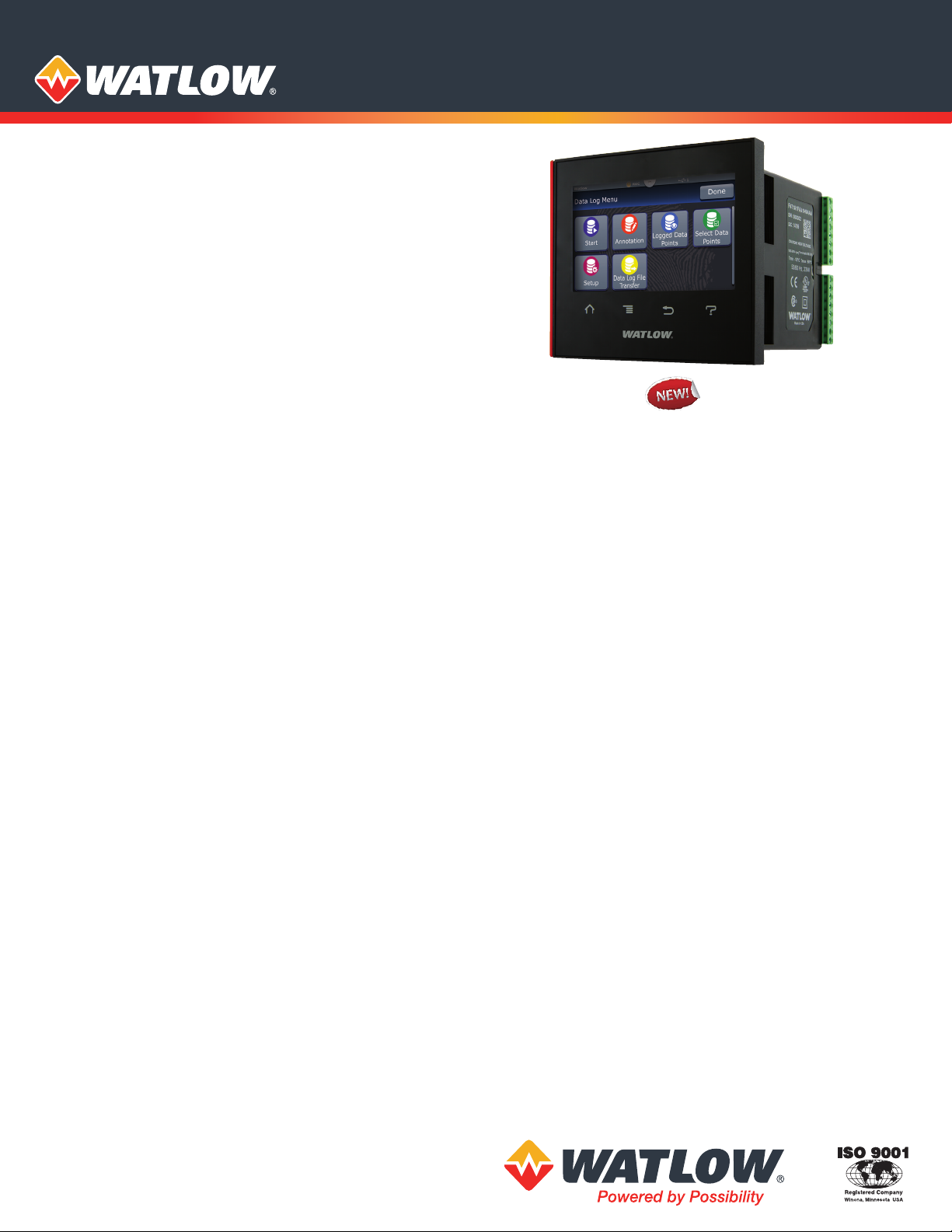
The D4T data logger from Watlow® offers a data logger with
a wide range of field removable I/O modules for maximum
design flexibility. Configurations can be custom tailored to
meet the scaling needs of a tremendous range of equipment
and applications while providing exactly the hardware types
required for compatibility. The D4T data logger also features
a 4.3 inch, color, graphical touch panel. Combining power,
flexibility and functionality, this new data logger offers
unmatched versatility, and its best-in-class ease of use could
very well make user manuals a thing of the past.
Features and Benefits
4.3-inch, color touch panel with high-resolution, graphical
user-interface
• Shortens learning curve and reduces operator errors
• Allows channels, alarms, inputs and outputs to be
personalized with user defined names
• Intuitive screens layout and menu navigation
• Programmable to show information in multiple languages
Data logging
• Easily complies with regulatory standards with ability to
choose encrypted, .CSV or both types of file formats for
tamper proof record needs
• Enables security using lock-out security levels for different
user groups
• Simplifies record keeping management with ability to
archive records to the cloud or a connected PC network
• Flexibility to select which parameters to log from one to up
to 128 points simultaneously
• Choose where you want to store the files—inside the
controller, on a connected USB memory device, or to a
connected PC anywhere in the world
• Record as fast as one time per 0.1 second or as slow as one
time per hour
1 to 24 channel data logger
• Scalable channels, pay for only what you need
• Compatible with temperature, altitude, humidity, ac
current and other 0-10VDC or 0-20mA process units
• Flexibility to meet diverse process applications
• Field expandable channels and I/O if application needs
grow in the future
Email and text alerts
• Notifies users of an event that has occurred such as an
alarm condition or analog input error
Trend screens
• Create up to four unique trend graph screens
• Graph any input sensor or process value
Batch processing with bar code data entry
• Easily collects and manages data records
• Inputs information from bar code scan for fast and easy
data entry
• Provides data security through password and data log
encrypted file options
• Improves manufacturing robustness via reminder screens
ensuring all data is entered during processing
• Helps ensure compliance with growing regulations and
minimizes warranty exposure
• Eliminates part processing skips or walk arounds due to
improved quality control
• Produces formatted data record report for easy receipt or
record management uses
COMPOSER® graphical configuration PC software
• Speeds up and simplifies commissioning
• Archives and documents controller setup
• Connects with controller easily via Ethernet
Many communications options available including Ethernet
Modbus® TCP and SCPI and EIA-232/485 Modbus® RTU
• Offers two USB host ports and one device port
• Simplifies methods to manually or automatically archive
data log files to cloud or PC
• Easily connect and transfer data log or configuration
set up files
Modular design
• Adapts quickly to evolving requirements
• Offers numerous types of field pluggable modules for
maximum flexibility and easiest compatibility
• Features scalable and modular firmware functions
• Delivers scalable input/output quantities from 1 to 24
Page 2

Key Features and Options
• Ethernet Modbus® TCP connectivity
• Multiple high-speed USB host ports
• Universal, thermistor and ac current measurement inputs
• Inputs and outputs expandable from 1 to 24
• Programmable timers, counters, math and logic
• Temperature, altitude, relative humidity and Vaisala® humidity
compensation
• USB configuration port
• Configuration settings can be stored and recalled
• Removable modules and connectors
• Front-panel mount and flush mounting options
• Right angle and front-screw terminal options
• UL® listed, CSA, CE, RoHS, W.E.E.E., FM
• Multi-language options
• English, German, French, Italian, Spanish, Japanese, Korean
and Chinese
• USB wired or wireless mouse user interface
• Use in hazardous location, dirty environments or
applications with gloves
Common Specifications
Line Voltage/Power
• Data retention upon power failure via nonvolatile memory
Functional Operating Range
• Type J: -346 to 2192°F (-210 to 1200°C)
• Type K: -454 to 2500°F (-270 to 1371°C)
• Type T: -454 to 750°F (-270 to 400°C)
• Type E: -454 to 1832°F (-270 to 1000°C)
• Type N: -454 to 2372°F (-270 to 1300°C)
• Type C: 32 to 4200°F (0 to 2315°C)
• Type D: 32 to 4200°F (0 to 2315°C)
• Type F: 32 to 2449°F (0 to 1343°C)
• Type R: -58 to 3214°F (-50 to 1767°C)
• Type S: -58 to 3214°F (-50 to 1767°C)
• Type B: 32 to 3300°F (0 to 1816°C)
• RTD (DIN): -328 to 1472°F (-200 to 800°C)
• Process: -1999 to 9999 units
Calibration Accuracy
• Calibration accuracy and sensor conformity: ±0.1% of
span, ±1°C at the calibrated ambient temperature and
rated line voltage
• Types R, S, B: ±0.2%
• Type T below -50°C: ±0.2%
• Calibration ambient temperature at 77°F ±5°F (25°C ±3°C)
• Accuracy span: 1000°F (540°C) min.
• Temperature stability: Typical ±0.1°F/°F (±0.1°C/°C) rise in
ambient max.
Conguration Diagnostics
• Indicates if modules present match the expected
conguration settings
USB Host Port
• Total of 2 available
• Version: USB 2.0 hi-speed
• Connector: USB Type A, high-retention
• Flash drive must be FAT32 le system
• Max. current 0.5A/port
System Conguration Requirements
• D4T has 6 slots for ex modules (FM)
• EIA-232/485 Modbus® RTU ex module, if used, must occupy
slot 6 location
• A maximum of two 10A SSR FM modules can be used in the F4T
and each will require space for 2 slots. Valid in slots 1, 2, 4 or 5
Wiring Termination—Touch-Safe Terminals
• Right-angle and front-screw terminal blocks for input, output
and power supply connections
• Input, output and power terminals: touch safe, removable,
12 to 30 AWG
D4T Base Specifications
Line Voltage/Power
• High voltage option: 100 to 240VAC +10/-15%, 50/60Hz ±5%
• Low voltage option: 24 to 28VAC/VDC+10/-15%, 50/60Hz ±5%
• Power consumption: 23 W, 54VA
Environment
• NEMA 4X/IP65 front panel mount conguration only
• Operating temperature: 0 to 122°F (-18 to 50°C)
• Storage temperature: -40 to 185°F (-40 to 85°C)
• Relative humidity: 0 to 90%, non-condensing
Agency Approvals
• UL®/EN 61010 Listed, File E185611 QUYX
• UL® 508 Reviewed
• AMS 2750 E compliant: Analog input process values. Tip: Maximize
eld calibration accuracy and uniformity by using advanced F4T
features such as Calibration Oset and Linearization Function
Blocks. Refer to user manual for details.
• RoHS by design, China RoHS Level 2, W.E.E.E.
• CE
• Windows® Hardware Certication
User Interface
• 4.3 inch TFT PCAP color graphic touch screen
• LED backlife >50K hours
• 4 keys: Home, Main Menu, Back, Help
• Multiple languages
• English, German, French, Italian, Spanish, Japanese, Korean
and Chinese
• USB wired or wireless mouse functionality
• Right click for 4 keys: Home, Main Menu, Back, Help
Inputs and Outputs
• Input sampling: 10Hz
• Output update: 10Hz
Communications
• Ethernet Modbus® TCP
• EIA-232/485 Modbus® RTU
• Isolated communications
Data Logging
• User selectable parameters: Up to a maximum of 128 active
parameters depending on conguration
• Logging interval: Programmable increments between 0.1 seconds
and 60 minutes if logging to internal memory. Logging directly to
USB; 1.0 seconds to 60 minutes
• File types: .CSV for standard data logging or proprietary format for
encrypted data log option
• Storage: 80MB internal memory or to USB memory stick
• File transfer: Internal memory to USB host port or to Ethernet
Modbus® TCP
• Transfer options: On demand by user or user programmable based
on when a new data log le record is available. Utilizes TFTP and
Samba protocols
• Record: Date and time stamped
Batch Processing with Bar Code Data Entry Via USB Scanner
• Compatible with many bar code types including Code 128,
Code 39, Extended Code 39, Data Matrix, Interleaved 2 of 5, ISSN,
SISAC, LOGMARS, QR, UCC/EAN-128 (GS1-128, UPC-A & E)
• Compatible with most USB scanner types such as Zebra DS4308,
DS2208, LI2208 and LS2208
• USB port provides 500mA max. power supply for bar code
scanner/base charging
• Display can show bar code elds up to a maximum length of
48 characters. Characters might wrap to 2 rows after 24 characters
• Program the bar code scanner to add an enter key (carriage return
feed) at the end of each bar code data eld sent to the F4T/D4T.
Refer to USB scanner user manual.
Trending
• 4 user programmable charts
• 6 pens available per chart
• View analog sensors and process values
Page 3

4.09 in.
(103.96 mm)
4.33 in.
(109.98 mm)
Real Time Clock with Battery Backup
• Accuracy (typical): +/-3ppm over -15 to 50°C
• Typical battery life: 10 years at 77°F (25°C)
• Field replaceable lithium battery
Number of Function Blocks by Ordering Option
Function Block Basic Set 1 Set 2
Alarm 6 8 14
Compare None 4 16
Counter None 4 16
Linearization 4 4 8
Logic None 12 24
Math None 12 24
Process Value 4 4 8
Special Output Function
(including compressor)
None 2 4
Timer None 6 16
Variable 4 12 24
Compare
• Greater than, less than, equal, not equal, greater than or equal, less
than or equal
Panel Mount Dimensions
4.62 in.
(117.4 mm)
Counters
• Counts up or down, loads predetermined value on load signal
Linearization
• Interpolated or stepped
Logic
• And, nand, or, nor, equal, not equal, latch, ip-op
Math
• Average, process scale, switch over, deviation scale,
dierential (subtract), ratio (divide), add, multiply, absolute
dierence, minimum, maximum, square root, sample and hold,
pressure-to-altitude and dew point
Process Value
• Sensor backup, average, crossover, wet bulb-dry bulb, switch over,
dierential (subtract), ratio (divide), add, multiply, absolute
dierence, minimum, maximum, square root, altitude, Vaisala®
relative humidity and pressure-to-altitude
Special Output Function
• Compressor control (cool and/or dehumidify with single
compressor), motorized valve, sequencer
Timers
• On pulse, delay, one shot or retentive
Variable
• User value for digital or analog variable
4.33 in.
(109.98 mm)
Slot 1
Slot 2 Slot 3
Accent Bar
4.73 in.
(120.14 mm)
Flush Mount Dimensions
4.09 in.
(103.96 mm)
4.62 in.
(117.4 mm)
4.09 in.
(103.96 mm)
0.50 in.
(12.7 mm)
Mounting Panel
4.81 in.
(122.1 mm)
Flushmount Bracket
Slot 4
Slot 5 Slot 6
USB Type A
(Quantity 2)
USB Mini B
Ethernet
Powered by Possibility
To be automatically connected to the nearest
North American Technical Sales Oce:
1-800-WATLOW2 • www.watlow.com
©2020 Watlow Electric Manufacturing Company all rights reserved.
International Technical Sales Offices:
Austria +43 6244 20129 0
China +86 21 3532 8532
France +33 1 41 32 79 70
Germany +49 7253 9400 0
Mounting
Panel
India +91 40 6661 2700
Italy +39 02 458 8841
Japan +81 3 3518 6630
Korea +82 2 2169 2600
Mexico +52 442 256 2200
Singapore +65 6773 9488
Spain +34 91 675 1292
Taiwan +886 7 288 5168
UK +44 115 964 0777
WIN-D4T-0120
Page 4

D4T Ordering Information
Base includes: 4.3 inch color graphical touch screen, standard bus communications, Ethernet Modbus® TCP and SCPI protocol.
Part Number
① ②
Model
D4
③
T = Touch screen
④
1 = Standard
⑤
J =
K =
L =
M =
⑥
1 =
2 =
3 =
4 =
5 =
6 =
7 =
8 =
⑦
A =
B =
C =
⑧ ⑨
AA =
⑩ ⑪
1A =
1B =
1C =
1D =
1E =
1F =
1G =
1H =
1J =
XX =
⑫
5 =
Watlow® and COMPOSER® are registered trademarks of Watlow Electric
Manufacturing Company.
UL® is a registered trademark of Underwriter’s Laboratories Incorporated.
Modbus® is a registered trademark of Schneider Automation Incorporated.
Vaisala® is a registered trademark of Vaisala OY Corporation.
Microsoft® and Windows® are registered trademarks of the Microsoft Corporation.
③
Base
Type
④
Application
Type
T
Data Logging and Trend Charts
Data logging
Data logging with encrypted les
Data logging with graphical trend charts
Data logging with encrypted les, graphical trend charts
and batch processing with bar code data entry.
Power Supply Voltage, Connector Style,
Power Supply
100 to 240VAC Right angle (standard) Yes
100 to 240VAC Right angle (standard) No
100 to 240VAC Front screw Yes
100 to 240VAC Front screw No
24 to 28VAC or VDC Right angle (standard) Yes
24 to 28VAC or VDC Right angle (standard) No
24 to 28VAC or VDC Front screw Yes
24 to 28VAC or VDC Front screw No
Basic Set Set 1 Set 2
X
Future Options
Documentation, Accent Bar, Replacement
Documentation
DVD / QSG
Yes X
Yes X
Yes X
Yes X
No X
No X
No X
No X
Replacement connectors only - for the model number
entered
Contact factory, other custom-firmware, preset parameters,
locked code, logo
None
⑤
Data
Logging
& Trend
Charts
Base Type
Application Type
Watlow Logo Screenprint
Power Supply
Connector
Function Blocks
X
Future Options
Connectors & Custom
Decorated Brush Aluminum
Gray Blue Red None
Additional Options
⑥
Power Supply
Voltage, Connector
Style, Watlow Logo
Screenprint
Accent Bar
⑦
Function
Blocks
Watlow
Logo
X
⑧ ⑨
Future
Options
⑩ ⑪
Documentation, Accent
Bar, Replacement
Connectors & Custom
AA
⑬ ⑭
Universal Input(s) (T/C, RTD 2- or 3-wire, 0-10VDC, 0-20mA)
U1 =
U2 =
U3 =
U4 =
U5 =
U6 =
Thermistor Input(s)
T1 =
T2 =
T3 =
T4 =
T5 =
T6 =
Universal Input(s) (T/C, RTD 2-wire, 0-10VDC, 0-20mA)
04 =
08 =
12 =
16 =
20 =
24 =
Thermistor Input(s)
TA =
TB =
TC =
TD =
TE =
TF =
Custom
XX =
Options below are not available with 6 or 24 channel input models
A =
Single Output
C =
E =
F =
Multiple Digital Inputs/Outputs
D =
P =
B =
J =
K =
T* =
L =
Communications
M =
Custom
X =
* Option “T” not available with digit 13 & 14, options U5, U6, T5, T6,
20, 24, TE and TF.
Number of Logging Channels & Input Hardware Types
1 channel
2 channels
3 channels
4 channels
5 channels
6 channels
1 channel
2 channels
3 channels
4 channels
5 channels
6 channels
4 channels
8 channels
12 channels
16 channels
20 channels
24 channels
4 channels
8 channels
12 channels
16 channels
20 channels
24 channels
Dierent channel quantity and combination options.
Contact factory for assistance.
⑮
None
1 switched dc/open collector
1 mechanical relay 5A, Form C output
1 universal process/retransmit
6 digital I/O
3 universal process/retransmit outputs
3 mechanical relay 5A, 2 Form C and 1 Form A (Form A
shares a common with 1 Form C)
4 mechanical relay 5A, Form A
2 SSRs Form A, 0.5 A
2 SSRs at 10A
4 SSRs at 2A each, SSRs grouped in 2 pairs with each pair
sharing a common
Modbus® RTU 232/485
Dierent output quantity and combination options.
Contact factory for assistance.
⑫
Additional
Options
5
Number of Auxiliary/Alarm Outputs,
Digital Inputs & Hardware
⑬ ⑭
Nbr. of Logging
Channels &
Input Hardware
Types
Nbr. of Auxiliary/
Alarm Outputs,
Digital Inputs &
Hardware
⑮
 Loading...