

Page 1
[ Care and Use ManUal ]
XseLeCt HIGH stRenGtH sILICa (Hss) HPLC CoLUMns
Contents
I. IntRoDUCtIon
II. ConeCtInG tHe CoLUMn to tHe HPLC sYsteM
a. Column Connection
b. Column Connectors and System Tubing Considerations
c. Band Spreading Minimization
d. Measuring System Band Spread Volume
e. Measuring Gradient Delay Volume
III. WateRs sMaLL PaRtICLe sIze (3.5 �m) CoLUMns
– Fast CHRoMatoGRaPHY
IV. CoLUMn eqUILIbRatIon
V. CoLUMn InstaLLatIon PRoCeDURe
VI. CoLUMn PeRFoRManCe VaLIDatIon
I. IntRoDUCtIon
Thank you for choosing an XSelect™ High Strength Silica (HSS) HPLC
column. The manufacture of XSelect HSS HPLC columns begins with
ultrapure reagents to control the chemical composition and purity of
the final product. XSelect HSS HPLC columns are manufactured in a
cGMP, ISO 9001:2000 certified plant with each step being conducted
within narrow tolerances. Every column is individually tested and
Certificates of Batch Analysis and a Performance Chromatogram are
provided with each column.
XSelect HSS HPLC columns are based on the same particle technol-
®
ogy and chemistries as ACQUITY UPLC
seamless transferability between HPLC and UPLC
HSS columns, thus enabling
®
separations.
VII. InItIaL CoLUMn eFFICIenCY DeteRMInatIon
VIII. CoLUMn UsaGe
a. Guard Columns
b. Sample Preparation
c. Recommended pH Range
d. Solvents
e. Pressure
f. Temperature
g. Scaling Up/Down Isocratic Methods
IX. CoLUMn CLeanInG, ReGeneRatInG anD stoRaGe
a. Cleaning and Regenerating
b. Storage
X. tRoUbLesHootInG
XSelect HSS HPLC Columns 1
Page 2
[ Care and Use ManUal ]
II. ConneCtInG tHe CoLUMn to tHe HPLC sYsteM
a. Column Connection
Handle the column with care. Do not drop or hit the column on a hard
surface as this may disturb the bed and affect its performance.
1. Correct connection of 1/16 inch outer diameter stainless steel
tubing leading to and from the column is essential for high-
quality chromatographic results.
2. An arrow on the column identification label indicates correct
direction of solvent flow.
3. When using standard stainless steel compression screw fittings,
it is important to ensure proper fit of the 1/16 inch outer diameter
stainless steel tubing. When tightening or loosening the compression
screw, place a 5/16 inch wrench on the compression screw and a
3/8 inch wrench on the hex head of the column endfitting.
Caution: If one of the wrenches is placed on the column flat during this
process, the endfitting will be loosened and leak. Under-tightening
compression screws or using worn ferrules can lead to solvent leaking.
Care should be taken to check all column connections for leaks to
avoid exposure to solvents and the hazards associated with such exposure
including risks to health and electrical connections.
ferrule depth be reset for optimal performance prior to installing
the XSelect HSS HPLC column. In a proper tubing/column connection
(Figure 2), the tubing touches the bottom of the column endfitting,
with no void between them.
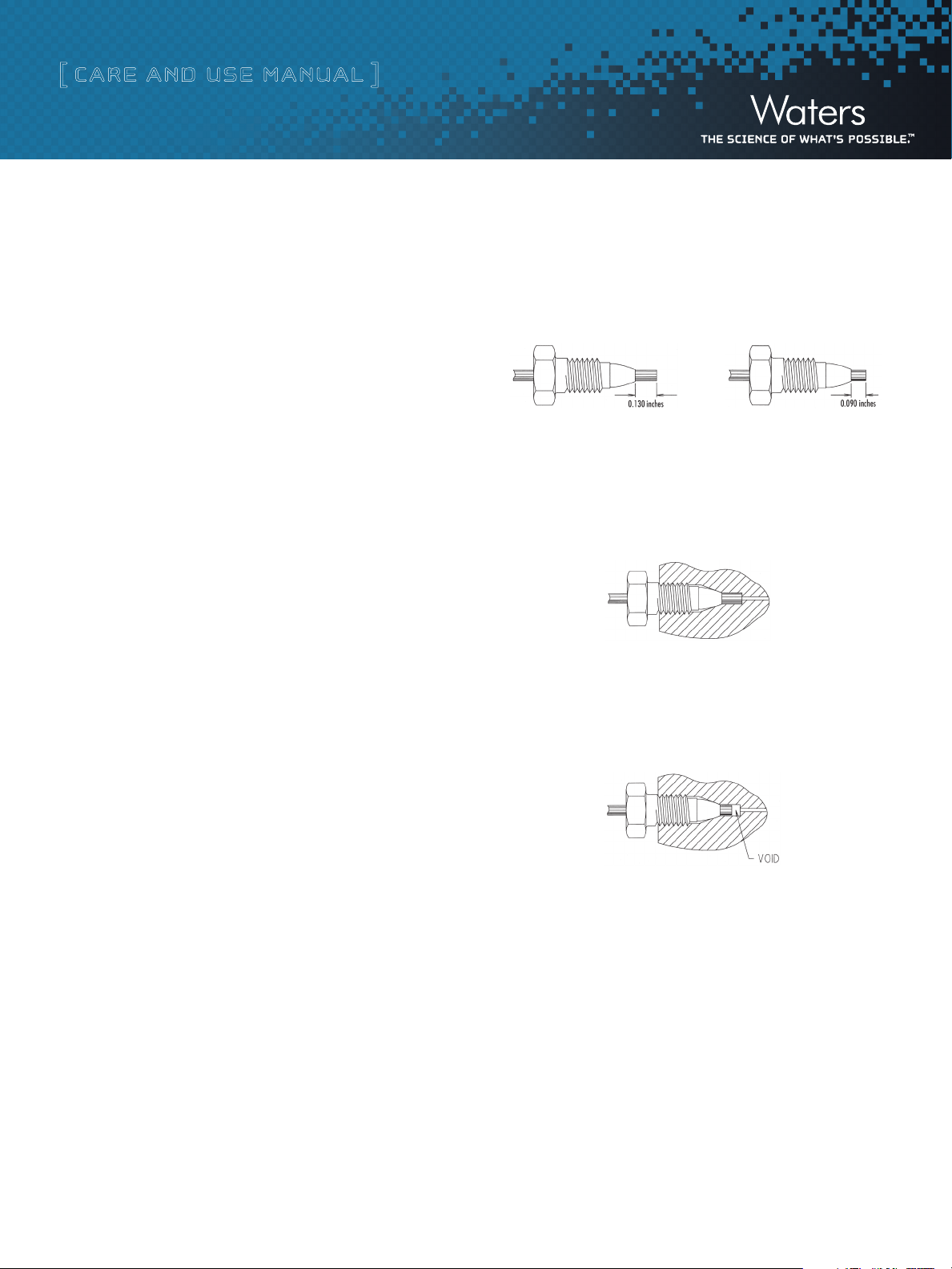
Figure 1: Waters and Parker Ferrule Types
Waters Ferrule Setting Parker Ferrule Setting
Figure 2: Proper Tubing/Column Connection
Tubing touches the bottom of the column endfitting, with no void
between them.
Attention: A void will occur if a Parker ferrule connection is used with
a Waters style endfitting (Figure 3). This will dramatically reduce the
efficiency of the column and cause peak shape distortion.
4. If a leak occurs between the stainless steel compression screw
fitting and the column endfitting, a new compression screw fitting,
tubing and ferrule must be assembled.
It is important to realize that extra column peak broadening can
destroy a successful separation. The choice of appropriate column
connectors and system tubing is discussed in detail below.
b. Column Connectors and System Tubing Considerations
Due to the absence of an industry standard, various column manufacturers
have employed different types of chromatographic column connectors.
The chromatographic performance of the separation can be negatively
affected if the style of the column endfittings does not match the
existing tubing ferrule setting. This section explains the differences
between Waters style and Parker style ferrules and endfittings (Figure
1). Each endfitting style varies in the required length of the tubing
protruding from the ferrule. XSelect HSS HPLC columns are equipped
with Waters style endfittings, which require a 0.130 inch ferrule. If
a non-Waters style column is presently being used, it is critical that
Figure 3: Parker Ferrule in a Waters Style Endfitting
To fix this problem: Cut the end of the tubing with the ferrule, place a
new ferrule on the tubing and make a new connection. Before tighten-
ing the screw, make sure that the tubing bottoms out in the endfitting
of the column.
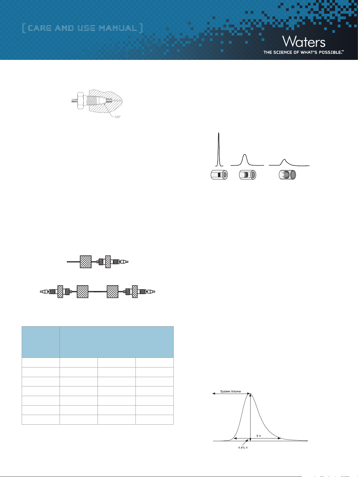
Conversely, if tubing with a Waters ferrule is connected to a column
with Parker style endfitting, the end of the tubing will bottom out
before the ferrule reaches its proper sealing position. This will leave a
gap and create a leak (Figure 4).
Caution: The connection will leak if a Waters ferrule is connected to a
column with a Parker style endfitting.
XSelect HSS HPLC Columns 2
Page 3
[ Care and Use ManUal ]
Figure 4: Waters Ferrule in a Parker Style Endfitting
There are two ways to fix the problem:
1. Tighten the screw a bit more. The ferrule moves forward, and
reaches the sealing surface. Do not overtighten since this may
break the screw.
2. Cut the tubing, replace the ferrule and make a new connection.
Alternatively, replace the conventional compression screw fitting
with an all-in-one PEEK
™
fitting (Waters Part Number PSL613315)
that allows resetting of the ferrule depth. Another approach is to use a
®
SLIPFREE
connector to ensure the correct fit. The fingertight SLIPFREE
connectors automatically adjust to fit all compression screw type
fittings without the use of tools (Figure 5).
Figure 5: Single and Double SLIPFREE Connectors
c. Band Spreading Minimization
Internal tubing diameter influences system band spreading and peak
shape. Larger tubing diameters cause excessive peak broadening and
lower sensitivity (Figure 6).
Figure 6: Effect of Connecting Tubing on System
0.005 inches
0.020 inches
0.040 inches
Diluted/Distorted Sample Band
d. Measuring System Band Spread Volume
This test should be performed on an HPLC system with a single wavelength
UV detector (not a Photodiode Array (PDA)).
1. Disconnect column from system and replace with a zero dead
volume union.
Table 1. Waters Part Numbers for SLIPFREE Connectors
SLIPFREE Type
and Tubing
Internal
Diameter
0.005” 0.010” 0.020”
Single 6 cm PSL 618000 PSL 618006 PSL 618012
Single 10 cm PSL 618002 PSL 618008 P SL 618014
Single 20 cm PSL 618004 PSL 618010 PSL 618016
Double 6 cm PSL 618001 P SL 618007 PSL 618013
Double 10 cm P SL 618 003 PS L 6180 09 PS L 618 015
Double 20 cm P SL 618005 PSL 618001 PSL 618017
Tubing Length
2. Set flow rate to 1 mL/min.
3. Dilute a test mix in mobile phase to give a detector sensitivity
0.5-1.0 AUFS (system start up test mix can be used which
contains uracil, ethyl and propyl parabens; Waters Part Number
WAT034544).
4. Inject 2 to 5 μL of this solution.
5. Using 5-Sigma Method measure the peak width at 4.4% of peak height:
Band Spreading (μL) = Peak Width (min) x Flow Rate (μL/min)
= 0.1 min x 1000 μL/min
= 100 μL
Figure 7: Determination of System Band Spread Volume Using
5-Sigma Method
XSelect HSS HPLC Columns 3
Page 4

[ Care and Use ManUal ]
In a typical HPLC system, the Band Spread Volume should be 100 μL
± 30 μL .
e. Measuring Gradient Delay Volume
1. Replace the column with a zero dead volume union.
2. Prepare eluent A (pure solvent, such as methanol) and eluent B
(solvent plus sample, such as 5.6 mg/mL propylparaben in
methanol).
3. Equilibrate the system with eluent A until a stable baseline is
achieved.
4. Switch to 100% eluent B.
5. Record the half height of the step and determine dwell volume
(Figure 8).
Figure 8: Determination of Dwell Volume
1.0
0.8
0.6
Au
0.4
0.2
0.0
Inflection
point time
Time
used when high efficiency and short analysis times are required.
These higher flow rates, however, lead to increased backpressure.
Note: Use a flow rate that is practical for your system.
2. Backpressure — Backpressures for columns with 3.5 μm particles
are higher than for 5 μm columns with the same dimensions.
Waters suggests using a shorter column to compensate for
increased backpressure and to obtain a shorter analysis time.
3. Temperature — Use a higher temperature to reduce backpressure
caused by smaller particle sizes. The recommended temperature
range for XSelect HSS HPLC columns is 20 °C to 45 °C. See
“Column Usage” for a discussion on elevated temperature use
with XSelect HSS HPLC columns.
4. Sampling Rate — Use a sampling rate of about 10 points per
second.
5. Detector Time Constant — Use a time constant of 0.1 seconds
for fast analyses.
IV. CoLUMn eqUILIbRatIon
XSelect HSS HPLC columns are packed and shipped in 100% acetonitrile.
It is important to ensure solvent compatibility before changing to a
new solvent. Equilibrate with a minimum of 10 column volumes of
the mobile phase to be used (refer to Table 2 for a listing of standard
column volumes).
The dwell volume should be less than 1 mL.
III. WateRs sMaLL PaRtICLe sIze (3.5 �m) CoLUMns
– Fast CHRoMatoGRaPHY
Waters columns with 3.5 μm particles provide faster and more efficient
separations without sacrificing column lifetime. This section describes
five parameters to consider when performing separations with columns
containing 3.5 μm particles.
Note: Columns that contain 3.5 μm particles have smaller pore-size
outlet frits to retain packing material than are used at the inlet. These
columns should not be backflushed.
1. Flow Rate — Compared to columns with 5 μm particles, columns
with 3.5 μm particles have higher optimum flow rates and are
XSelect HSS HPLC Columns 4
Table 2. Standard Column Volumes in mL (Multiply by 10 for
Equilibration Mobile Phase Volumes)
Column Volume (mL)
Column
Length
20 mm .10 .21 .50 2.4
30 mm
50 mm
75 mm .26 .53 1.3 6.0
100 mm
150 mm
250 mm
Column Internal Diameter (mm)
2.1
.11 2.4 0.5 –
.17 .35 .83 4.0
.35 .71 1.7 8.0
.52 1.1 2.5 12
.87 1.8 4.2 20
3.0 4.6 10
Page 5

[ Care and Use ManUal ]
V
. CoLUMn InstaLLatIon PRoCeDURe
VII. InItIaL CoLUMn eFFICIenCY DeteRMInatIon
Note: The flow rates given in the procedure below are for a typical
4.6 mm i.d. column. Scale the flow rate up or down accordingly based
upon the column i.d., length, particle size and backpressure of the
XSelect HSS HPLC column being installed. See “Scaling Up/Down” for
calculating flow rates when changing column i.d. and/or length.
1. Purge the pumping system and connect the inlet end of the
column to the injector outlet.
2. Set the pump flow to 0.1 mL/min and increase to 1 mL/min over
5 minutes.
3. When the mobile phase is flowing freely from the column outlet,
stop the flow, then attach the column to the detector. This prevents
entry of air into the detector and provides more rapid baseline
equilibration.
Caution: Care should be taken to check column connections for
leaks to avoid exposure to solvents and the hazards associated
with such exposure including risks to health and electrical connections.
4. When the mobile phase is changed, gradually increase the flow
rate of the new mobile phase from 0.0 mL/min to 1.0 mL/min in
0.1 mL/min increments.
1. Perform an efficiency test on the column before using it. Waters
recommends using a suitable solute mixture, as found in the
“Performance Test Chromatogram”, to verify the performance of
the column upon receipt.
2. Determine the number of theoretical plates (N) and use for periodic
comparison.
3. Repeat the test periodically to track column performance over
time. Slight variations may be obtained on two different HPLC
systems due to the quality of the connections, operating envi-
ronment, system electronics, reagent quality, column condition
and operator technique.
Note: If 1) is performed, the isocratic efficiencies measured in your
laboratory may be less than those given on the Waters “Performance
Test Chromatogram”. This is normal. The Waters isocratic column
testing systems have been modified in order to achieve extremely low
system volumes. This presents a more challenging test of how well
the column was packed. This guarantees the highest quality packed
column. These special testing systems have been modified to such an
extent that they are not commercially viable and have limited method
flexibility other than isocratic column testing.
5. Once a steady backpressure and baseline have been achieved,
the column is ready to be used (or equilibrated).
Note: If mobile-phase additives are present in low concentrations
(e.g., ion-pairing reagents), 100 to 200 column volumes may be
required for complete equilibration. In addition, mobile phases that
contain formate (e.g., ammonium formate, formic acid, etc.) may also
require slightly longer initial column equilibration times.
VI. CoLUMn PeRFoRManCe VaLIDatIon
Each XSelect HSS HPLC column comes with a Certificate of Batch
Analysis and a Performance Test Chromatogram. The Certificate of
Analysis is specific to each batch of packing material and includes
the batch number, analysis of unbonded particles, analysis of bonded
particles and chromatographic results and conditions. The Performance
Test Chromatogram is specific to each individual column and contains
information such as batch number, column serial number, USP plate
count, USP tailing factor, capacity factor and chromatographic results
and conditions. These data should be stored for future reference.
XSelect HSS HPLC Columns 5
VIII. CoLUMn UsaGe
Caution: Accumulation of particulates from solvents, samples, or
pump seals may cause the column backpressure to increase over time.
This may lead to a system shutdown or leaking of column connections.
Accumulation of contaminants from “dirty” samples at the column
inlet may lead to a loss of resolution or ion suppression in a mass
spectrometer, resulting in erroneous results.
To ensure the continued high performance of XSelect HSS HPLC
columns and cartridges, follow these guidelines:
a. Guard Columns
Use a Waters Sentry guard cartridge of matching i.d., chemistry and
particle size between the injector and main column. For best results,
the guard column should be replaced prior to the observation of a
substantial loss in resolution or increase in system backpressure. It is
important to use a high-performance matching guard column to protect
Page 6

[ Care and Use ManUal ]
the main column while not compromising or changing analytical
resolution.
b. Sample Preparation
1. Sample impurities often contribute to column contamination.
®
Use Waters Oasis
or Sep-Pak® solid-phase extraction cartridges/
columns of the appropriate chemistry to cleanup the sample
before analysis.
2. It is preferable to prepare the sample in mobile phase or a solvent
that is weaker (less organic modifier) than the mobile phase.
3. If the sample is not dissolved in the mobile phase, ensure that
the sample and diluent are miscible in the mobile phase(s) in
order to avoid sample and/or diluent precipitation.
4. Filter sample through a 0.2 µm membrane to remove particulates.
If the sample is dissolved in a solvent that contains an organic
modifier (e.g., acetonitrile, methanol, etc.) ensure that the membrane
material does not dissolve in the solvent. Contact the membrane
manufacturer with solvent compatibility questions. Alternatively,
centrifugation for 20 minutes at 8000 rpm, followed by the
careful transfer of the supernatant liquid to an appropriate vial,
could be considered.
c. Recommended pH Range
Table 3: Buffer recommendations for using HSS HPLC columns from
pH 1 to 7
Buffer
Additive or
Buffer
TFA 0.3 – Volatile Yes
Formic
Acid
Acetic Acid 4.76 – Volatile Ye s
Formate
(NH
COOH)
4
Acetate
(NH
CH-
4
COOH)
2
Phosphate 1 2.15
Phosphate 2 7.2
Range
pKa
3.75 – Volatile Ye s
3.75
4.76
(±1 pH
unit)
2.75 –
4.75
3.76 –
5.76
1.15 –
3.15
6.20 –
8.20
Volatility
Volatile Yes
Volatile Yes
volatile
volatile
Non-
Non-
Used for
Mass
Spec?
Ion pair additive, can suppress
MS signal. Used in the 0.01-
0.1% range.
Maximum buffering obtained
when used with Ammonium
Formate salt. Used in 0.1-1.0%
range.
Maximum buffering obtained
when used with Ammonium
Acetate salt. Used in 0.1-1.0%
range.
Used in the 1-10mM range.
Note: sodium or potassium salts
are not volatile.
Used in the 1-10mM range.
Note: sodium or potassium salts
are not volatile.
Traditional low pH buffer, good
No
UV transparency.
Much shorter colum lifetimes
No
will be realized using p hosphate
at pH 7.
Comments
Chemistry pH Range
XSelect HSS Cyano 2-8
XSelect HSS PF P 2-8
XSelect HSS T3 2-8
XSelect HSS C
XSelect HSS C
SB 2-8
18
18
1-8
Column lifetime will vary depending upon the temperature, type and
concentration of buffer used. A listing of recommended and non-
recommended buffers is given in Table 3. Please use this as a guideline
when developing methods.
Attention: Operating at the upper or lower end of the pH range in
combination with elevated temperatures will lead to shorter column
lifetime and/or may result in the column generating high backpressure.
XSelect HSS HPLC Columns 6
d. Solvents
To maintain maximum column performance, use high quality
chromatography grade solvents. Filter all aqueous buffers prior to
use. The addition of at least 5% organic to buffers is recommended
to discourage bacterial growth. Acrodisc
®
filters are recommended.
Solvents containing suspended particulate materials will generally
clog the outside surface of the inlet frit of the column. This will result
in higher operating pressure and poorer performance.
Degas all solvents thoroughly before use to prevent bubble formation
in the pump and detector. The use of an on-line degassing unit is also
recommended. This is especially important when running low pressure
gradients since bubble formation can occur as a result of aqueous and
organic solvent mixing during the gradient.
Page 7

[ Care and Use ManUal ]
e. Pressure
XSelect HSS HPLC columns can tolerate pressures of up to 6,000 psi
(400 bar or 40 Mpa) although pressures greater than 4,000 - 5,000 psi
should be avoided in order to maximize column and system lifetimes,
and the risk of system shutdowns and leaking.
f. Temperature
Temperatures between 20 ˚C - 45 ˚C are recommended for operat-
ing XSelect HSS HPLC columns in order to enhance selectivity, lower
solvent viscosity and increase mass transfer rates. However, any
temperature rise above ambient will have a negative effect on life-
time which will vary depending on the pH and buffer conditions used.
The combination of operating at elevated temperatures and at pH
extremes should be avoided.
g. Scaling Up/Down Isocratic Methods
The following formulas will allow scale up or scale down, while maintaining
the same linear velocity (retention time), and provide new sample
loading values:
If column i.d. and length are altered: F
or: Load
or: Inj vol
= Load1(r2/r1)2(L2/L1)
2
= Inj vol2 (r2/r1)2 (L2/L1)
1
= F1(r2/r1)2
2
Where: r = Radius of the column, in mm
F = Flow rate, in mL/min
L = Length of column, in mm
1 = Original, or reference column
2 = New column
For Normal-Phase Conditions:
The XSelect HSS Cyano column can be used for both reversed-phase
separations as well as normal-phase separations. The column is
originally shipped in acetonitrile and is ready to use for reversed-
phase conditions. If you intend to use the column for normal-phase
applications you will need to condition the column with the following
procedure:
1. Flush the column with a minimum of 20 column volumes of
100% methanol using a low flow rate to avoid overpressuring
the LC system. Refer to Table 2 for minimum solvent volume.
2. Flush the column with a minimum of 20 column volumes of
100% isopropanol using a low flow rate to avoid overpressuring
the LC system. Refer to Table 2 for the minimum solvent volume.
3. Flush the column with a minimum of 20 column volumes of
100% dichloromethane using a low flow rate to avoid overpressuring
the LC system. Refer to Table 2 for the minimum solvent volume.
4. Flush the column with the intended mobile-phase conditions until
a stable baseline is achieved.
b. Storage
For periods longer than four days, store the column in 100% acetonitrile.
Do not store columns in buffered eluents. If the mobile phase
contained a buffer salt, flush the column with 10 column volumes
of HPLC grade water (see Table 2 for common column volumes) and
replace with 100% acetonitrile for storage. Failure to perform this
intermediate step could result in precipitation of the buffer salt in the
column when 100% acetonitrile is introduced.
XIII. CoLUMn CLeanInG, ReGeneRatInG anD stoRaGe
a. Cleaning and Regenerating
A sudden increase in pressure or shift in retention or resolution may
indicate contamination of the column.
Flush with a neat organic solvent to remove the non-polar
contaminant(s). If this flushing procedure does not solve the problem,
purge the column with a sequence of progressively more non-polar
solvents. For example, switch from water to tetrahydrofuran to methylene
chloride. Return to the standard mobile-phase conditions by reversing
the sequence.
XSelect HSS HPLC Columns 7
Completely seal column to avoid evaporation and drying out of the bed.
Note: If a column has been run with a formate-containing mobile
phase (e.g., ammonium formate, formic acid, etc.) and is flushed to
remove the buffer, slightly longer equilibration times may be required
after the column is re-installed and run again with a formate-containing
mobile phase.
For Normal-Phase Use:
For rapid equilibration upon start-up, it is recommended that you
store the XSelect HSS Cyano column in the mobile phase that is com-
monly used for your normal-phase separation. Completely seal the
column to avoid evaporation and drying out of the bed.
Page 8

[ Care and Use ManUal ]
X. tRoUbLesHootInG
Changes in retention time, resolution, or backpressure are often due
to column contamination (refer to “Column Cleaning, Regenerating
and Storage”). Information on column troubleshooting problems may
be found in HPLC Columns Theory, Technology and Practice, U.D.
Neue, (Wiley-VCH, 1997) or the Waters HPLC Troubleshooting Guide
(Literature Code 720000181EN).
Sales Offices
Austria and European Export
(Central South Eastern Europe,
CIS and Middle East)
43 1 877 18 07
Australia 61 2 9933 1777
Belgium 32 2 726 1000
Brazil 55 11 4134 3788
Canada 1 800 252 4752
China 86 10 5293 6688
Czech Republic
420 2 617 11384
Denmark 45 46 59 8080
Finland 358 9 5659 6288
France 33 1 30 48 72 00
Germany 49 6196 400 600
Hong Kong 852 2964 1800
Hungary 36 1 350 5086
India 91 80 2837 1900
Ireland 353 1 448 1500
Italy 39 02 265 0983
Japan 81 3 3471 7191
Korea 82 2 6300 4800
Mexico 52 55 52 00 1860
The Netherlands
31 76 508 7200
Norway 47 6 384 6050
Poland 48 22 833 4400
Puerto Rico 1 787 747 8445
Russia/CIS 7 495 727 4490/
290 9737
Singapore 65 6593 7100
Spain 34 93 600 9300
Sweden 46 8 555 115 00
Switzerland 41 56 676 7000
Taiwan 886 2 2501 9928
United Kingdom
44 208 238 6100
All other countries:
Waters Corporation U.S.A.
1 508 478 2000
1 800 252 4752
www.waters.com
©2011 Waters Corporation. Waters, XSelect, ACQUITY UPLC,
UPLC, Sentry, Oasis, SepPak, and T he Science of What’s Possible
are trademarks of Waters Corporation. SLIPF REE is a trademark
of Thermo Fisher Scientific, Inc. Acrodisc is a trademark of Pall
Corporation. All other trademarks are the property of their
respective owners.
October 2011 720003994EN Rev B KK-PDF
XSelect HSS HPLC Columns 8
Waters Corporation
34 Maple Street
Milford, MA 01757 U.S.A.
T: 1 508 478 2000
F: 1 508 872 1990
www.waters.com
 Loading...