

Page 1

Waters Xevo G2-XS QTof
Overview and Maintenance Guide
715004496/Revision B
Copyright © Waters Corporation 2015
All rights reserved
Page 2

ii April 2, 2015, 715004496 Rev. B
Page 3

General Information
Copyright notice
© 2014 – 2015 WATERS CORPORATION. PRINTED IN THE UNITED
STATES OF AMERICA AND IN IRELAND. ALL RIGHTS RESERVED. THIS
DOCUMENT OR PARTS THEREOF MAY NOT BE REPRODUCED IN ANY
FORM WITHOUT THE WRITTEN PERMISSION OF THE PUBLISHER.
The information in this document is subject to change without notice and
should not be construed as a commitment by Waters Corporation. Waters
Corporation assumes no responsibility for any errors that may appear in this
document. This document is believed to be complete and accurate at the time
of publication. In no event shall Waters Corporation be liable for incidental or
consequential damages in connection with, or arising from, its use. For the
most recent revision of this document, consult the Waters Web site
(waters.com).
Trademarks
Waters, “THE SCIENCE OF WHAT’S POSSIBLE.”, ACQUITY,
ACQUITY UPC
UNIFI, UPLC, Waters Quality Parts, and Xevo are registered trademarks of
Waters Corporation, and iKey, IntelliStart, ionKey, ionKey/MS, IonSABRE,
LockSpray, NanoFlow, NanoLockSpray, OpenLynx, pDRE, StepWave,
TargetLynx, and ZSpray are trademarks of Waters Corporation.
2
, ACQUITY UPLC, Connections INSIGHT, ESCi, MassLynx,
LEYBONOL is a registered trademark of Oerlikon Leybold Vacuum GmbH.
POZIDRIV is a registered trademark of Phillips Screw Company, Inc.
Swagelok is a registered trademark of Swagelok Company.
Tygon is a registered trademark of Saint-Gobain Performance Plastics Corp.
Viton is a registered trademark of E. I. du Pont de Nemours and Company.
Windows is a registered trademark of Microsoft Corporation in the United
States and/or other countries.
Xylan is a registered trademark of Whitford Corporation.
PEEK is a trademark of Victrex plc.
Super Flangeless and SealTight are trademarks of Upchurch Scientific, Inc.
April 2, 2015, 715004496 Rev. B iii
Page 4

TaperTip is a trademark of New Objective, Inc.
Valco is a trademark of Valco Instruments, Inc.
Other registered trademarks or trademarks are the sole property of their
owners.
Customer comments
Waters’ Technical Communications organization invites you to report any
errors that you encounter in this document or to suggest ideas for otherwise
improving it. Help us better understand what you expect from our
documentation so that we can continuously improve its accuracy and
usability.
We seriously consider every customer comment we receive. You can reach us
at tech_comm@waters.com.
Contacting Waters
Contact Waters with enhancement requests or technical questions regarding
the use, transportation, removal, or disposal of any Waters product. You can
reach us via the Internet, telephone, or conventional mail.
Waters contact information:
Contacting medium Information
Internet The Waters Web site includes contact
Telephone and fax From the USA or Canada, phone
Conventional mail Waters Corporation
iv April 2, 2015, 715004496 Rev. B
information for Waters locations worldwide.
Visit www.waters.com.
800 252-4752, or fax 508 872 1990.
For other locations worldwide, phone and fax
numbers appear in the Waters Web site.
34 Maple Street
Milford, MA 01757
USA
Page 5

Safety considerations
Some reagents and samples used with Waters instruments and devices can
pose chemical, biological, or radiological hazards (or any combination thereof).
You must know the potentially hazardous effects of all substances you work
with. Always follow Good Laboratory Practice, and consult your organization’s
standard operating procedures.
Safety hazard symbol notice
Documentation needs to be consulted in all cases where the symbol is
used to find out the nature of the potential hazard and any actions which have
to be taken.
Considerations specific to the Xevo G2-XS QTof
Solvent leakage hazard
The source exhaust system is designed to be robust and leak-tight. Waters
recommends you perform a hazard analysis assuming a maximum leak into
the laboratory atmosphere of 10% LC eluate.
Warning:
• To confirm the integrity of the source exhaust system, renew
the source O-rings at intervals not exceeding one year.
• To avoid chemical degradation of the source O-rings, which can
withstand exposure only to certain solvents (see page 305),
determine whether any solvents you use that are not listed are
chemically compatible with the composition of the O-rings.
April 2, 2015, 715004496 Rev. B v
Page 6
Spilled solvents hazard
Prohibited: To avoid injury or equipment damage caused by spilled
solvent, do not place reservoir bottles on top of the instrument or on its
front ledge, unless in the bottle tray provided.
Flammable solvents hazard
Warning: To prevent ignition of flammable solvent vapors in the
enclosed space of a mass spectrometer’s ion source, ensure that nitrogen
flows continuously through the source. The nitrogen supply pressure
must not fall below 400 kPa (4.0 bar, 60 psi) during an analysis
requiring the use of flammable solvents. Also a gas-fail device must be
installed, to interrupt the flow of LC solvent should the nitrogen supply
fail.
When using flammable solvents, ensure that a stream of nitrogen
continuously flushes the instrument’s source, and the nitrogen supply
pressure remains above 400 kPa (4.0 bar, 60 psi). You must also install a
gas-fail device that interrupts the solvent flowing from the LC system in the
event the supply of nitrogen fails.
vi April 2, 2015, 715004496 Rev. B
Page 7

High temperature hazard
Source ion block assembly
Warning: The source ion block, located behind the source enclosure
assembly, can become hot. To avoid burn injuries, ensure the source
heater is turned off and the ion block is cool before performing
maintenance on these components.
Mass spectrometer high temperature hazard:
April 2, 2015, 715004496 Rev. B vii
Page 8
High voltage hazard
Warning:
• To avoid electric shock, do not remove the mass spectrometer’s
protective panels. The components they cover are not
user-serviceable.
• To avoid nonlethal electric shock when the instrument is in Operate
mode, avoid touching the areas marked with the high voltage
warning symbol. To touch those areas, first put the instrument in
Standby mode.
Hazards associated with removing an instrument from service
Warning: To avoid personal contamination with biohazards,
toxic materials, and corrosive materials, wear
chemical-resistant gloves during all phases of instrument
decontamination.
Warning: To avoid puncture injuries, handle syringes, fused silica lines,
and borosilicate tips with extreme care.
When you remove the instrument from use to repair or dispose of it, you must
decontaminate all of its vacuum areas. These are the areas in which you can
expect to encounter the highest levels of contamination:
• Source interior
• Waste tubing
• Exhaust system
• Rotary pump oil (where applicable)
The need to decontaminate other vacuum areas of the instrument depends on
the kinds of samples the instrument analyzed and their levels of
concentration. Do not dispose of the instrument or return it to Waters for
repair until the authority responsible for approving its removal from the
premises specifies the extent of decontamination required and the level of
residual contamination permissible. That authority must also prescribe the
method of decontamination to be used and the appropriate protection for
personnel undertaking the decontamination process.
You must handle items such as syringes, fused silica lines, and borosilicate
tips used to carry sample into the source area in accordance with laboratory
viii April 2, 2015, 715004496 Rev. B
Page 9

procedures for contaminated vessels and sharps. To avoid contamination by
carcinogens, toxic substances, or biohazards, you must wear
chemical-resistant gloves when handling or disposing of used oil.
Bottle placement prohibition
Prohibited: To avoid injury from electric shock or fire, and to prevent
damage to the workstation and ancillary equipment, do not place objects
filled with liquid—such as solvent bottles—on these items, or expose
them to dripping or splashing liquids.
Notice: To prevent spillages, do not lift the bottle tray while it is full of
bottles.
FCC radiation emissions notice
Changes or modifications not expressly approved by the party responsible for
compliance, could void the users authority to operate the equipment. This
device complies with Part 15 of the FCC Rules. Operation is subject to the
following two conditions: (1) this device may not cause harmful interference,
and (2) this device must accept any interference received, including
interference that may cause undesired operation.
Electrical power safety notice
Position the instrument and ancillary equipment in positions where it is easy
to reach and disconnect the power cable from the instrument’s rear panel.
Safety advisories
Consult Appendix A for a comprehensive list of warning advisories and
notices.
April 2, 2015, 715004496 Rev. B ix
Page 10
Operating the Xevo G2-XS QTof
When operating the Xevo® G2-XS QTof, follow standard quality-control (QC)
procedures and the guidelines presented in this section.
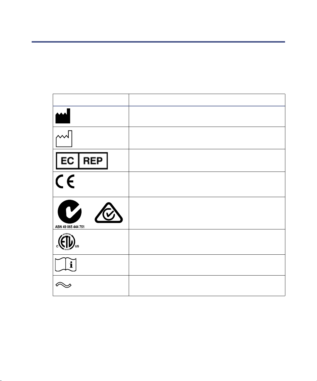
Applicable symbols
Symbol Definition
Manufacturer
Date of manufacture
Authorized representative of the European
Community
Confirms that a manufactured product complies
with all applicable European Community
directives
Australia EMC compliant
or
x April 2, 2015, 715004496 Rev. B
Confirms that a manufactured product complies
with all applicable United States and Canadian
safety requirements
Consult instructions for use
Alternating current
Page 11

Symbol Definition
5()
Audience and purpose
This guide is intended for operators of varying levels of experience. It provides
an overview of the instrument, and explains how to prepare it, change its
modes of operation, and maintain it.
Electrical and electronic equipment with this
symbol may contain hazardous substances and
should not be disposed of as general waste.
For compliance with the Waste Electrical and
Electronic Equipment Directive (WEEE)
2012/19/EU, contact Waters Corporation for the
correct disposal and recycling instructions.
Serial number
Part number catalog number
Intended use of the Xevo G2-XS QTof
Waters designed the orthogonal acceleration, time-of-flight Xevo G2-XS QTof
for use as a research tool to deliver authenticated mass measurement. The
Xevo G2-XS QTof is for research use only and is not intended for use in
diagnostic applications.
Calibrating
To calibrate LC systems, follow acceptable calibration methods using at least
five standards to generate a standard curve. The concentration range for
standards should cover the entire range of QC samples, typical specimens,
and atypical specimens.
To calibrate the Xevo G2-XS QTof, consult the instrument’s online Help
system.
April 2, 2015, 715004496 Rev. B xi
Page 12

Quality control
Routinely run three QC samples that represent subnormal, normal, and
above-normal levels of a compound. If sample trays are the same or very
similar, vary the location of the QC samples in the trays. Ensure that QC
sample results fall within an acceptable range, and evaluate precision from
day to day and run to run. Data collected when QC samples are out of range
might not be valid. Do not report these data until you are certain that the
instrument performs satisfactorily.
When analyzing samples from a complex matrix such as soil, tissue,
serum/plasma, whole blood, and other sources, note that the matrix
components can adversely affect LC/MS results, enhancing or suppressing
ionization. To minimize these matrix effects, adopt the following measures:
• Prior to the instrumental analysis, use appropriate sample
pretreatment such as protein precipitation, liquid/liquid extraction
(LLE), or solid phase extraction (SPE) to remove matrix interferences.
• Whenever possible, verify method accuracy and precision using
matrix-matched calibrators and QC samples.
• Use one or more internal standard compounds, preferably isotopically
labeled analytes.
Equipment misuse notice
If the equipment is used in a manner not specified by the manufacturer, the
protection provided by the equipment may be impaired.
xii April 2, 2015, 715004496 Rev. B
Page 13

EMC considerations
Canada spectrum management emissions notice
This class A digital product apparatus complies with Canadian ICES-001.
Cet appareil numérique de la classe A est conforme à la norme NMB-001.
ISM Classification: ISM Group 1 Class A
This classification has been assigned in accordance with CISPR 11 Industrial
Scientific and Medical, (ISM) instrument requirements. Group 1 products
apply to intentionally generated and/or used conductively coupled
radio-frequency energy that is necessary for the internal functioning of the
equipment. Class A products are suitable for use in all establishments other
than residential locations and those directly connected to a low voltage power
supply network supplying a building for domestic purposes.
There may be potential difficulties in ensuring electromagnetic compatibility
in other environments due to conducted as well as radiated disturbances.
Do not use the equipment in close proximity to sources of strong
electromagnetic radiation (for example, unshielded intentional RF sources), as
these may interfere with the equipment’s proper operation.
This equipment complies with the emission and immunity requirements
described in the relevant parts of IEC/EN 61326: Electrical equipment for
measurement, control and laboratory use — EMC requirements.
April 2, 2015, 715004496 Rev. B xiii
Page 14

EC authorized representative
Waters Corporation
Stamford Avenue
Altrincham Road
Wilmslow SK9 4AX UK
Telephone: +44-161-946-2400
Fax: +44-161-946-2480
Contact: Quality manager
xiv April 2, 2015, 715004496 Rev. B
Page 15

Table of Contents
General Information .................................................................................... iii
Copyright notice .................................................................................................. iii
Trademarks ........................................................................................................... iii
Customer comments ............................................................................................ iv
Contacting Waters ............................................................................................... iv
Safety considerations ........................................................................................... v
Safety hazard symbol notice................................................................................ v
Considerations specific to the Xevo G2-XS QTof................................................ v
FCC radiation emissions notice ......................................................................... ix
Electrical power safety notice ............................................................................ ix
Safety advisories................................................................................................. ix
Operating the Xevo G2-XS QTof ........................................................................ x
Applicable symbols .............................................................................................. x
Audience and purpose......................................................................................... xi
Intended use of the Xevo G2-XS QTof ............................................................... xi
Calibrating .......................................................................................................... xi
Quality control .................................................................................................. xii
Equipment misuse notice ................................................................................. xii
EMC considerations ......................................................................................... xiii
Canada spectrum management emissions notice .......................................... xiii
ISM Classification: ISM Group 1 Class A ...................................................... xiii
EC authorized representative ......................................................................... xiv
1 Waters Xevo G2-XS QTof Overview ..................................................... 23
Waters Xevo G2-XS QTof .................................................................................. 24
IntelliStart technology....................................................................................... 25
ACQUITY Xevo G2-XS QTof UPLC/MS systems............................................. 26
Software and data system ................................................................................. 29
April 2, 2015, 715004496 Rev. B xv
Page 16

LockSpray source and ionization modes ..................................................... 31
Electrospray ionization (ESI)............................................................................ 32
Atmospheric pressure chemical ionization (APCI) .......................................... 32
Combined electrospray/atmospheric pressure chemical ionization (ESCi) .... 33
Atmospheric solids analysis probe (ASAP)....................................................... 33
NanoLockSpray source and ionization modes ........................................... 34
Combined APPI/APCI source .......................................................................... 36
Atmospheric pressure gas chromotography (APGC) source ................... 36
ionKey source ..................................................................................................... 37
IntelliStart Fluidics system ............................................................................. 38
IntelliStart Fluidics system physical layout .................................................... 39
System operation ............................................................................................... 40
Ion optics .............................................................................................................. 41
Leak sensors ........................................................................................................ 43
Vacuum system ................................................................................................... 43
2 Preparing the Mass Spectrometer for Operation ............................ 45
Starting the mass spectrometer ..................................................................... 46
Verifying the instrument’s state of readiness .................................................. 48
Monitoring the mass spectrometer LEDs......................................................... 48
Calibration ......................................................................................................... 48
Flow rates for the Xevo G2-XS QTof system .................................................... 49
Preparing the IntelliStart Fluidics system .................................................. 49
Installing the reservoir bottles.......................................................................... 49
Adjusting the solvent delivery tube positions .................................................. 52
Purging the pump .............................................................................................. 53
xvi April 2, 2015, 715004496 Rev. B
Page 17

Rebooting the mass spectrometer .................................................................. 53
Leaving the mass spectrometer ready for operation ................................ 54
Emergency shutdown of the mass spectrometer ........................................ 54
3 Configuring the LockSpray Source .................................................... 55
Configuring the LockSpray source ................................................................ 56
Configuring for ESI mode ................................................................................ 57
Installing the ESI probe .................................................................................... 57
Removing the ESI probe.................................................................................... 61
Configuring for APCI mode ............................................................................. 62
Installing the IonSABRE II probe .................................................................... 62
Removing the IonSABRE II probe .................................................................... 65
Configuring for ESCi mode ............................................................................. 66
Optimizing the ESI probe for ESCi operation.................................................. 66
4 Configuring the NanoLockSpray Source .......................................... 67
Overview of the NanoLockSpray source ...................................................... 68
Sample sprayer .................................................................................................. 69
LockSpray sprayer............................................................................................. 69
NanoFlow gas supply......................................................................................... 70
Purge gas............................................................................................................ 70
Sprayer platform adjuster assembly................................................................. 70
April 2, 2015, 715004496 Rev. B xvii
Page 18

Selecting and configuring the NanoLockSpray source ............................ 71
Deploying the sprayer platform adjuster assembly .................................. 72
Adjusting the sprayer tip position ................................................................. 73
Setting up the camera ....................................................................................... 74
Optional glass-capillary sprayer .................................................................... 75
5 Installing and removing the ionKey source ..................................... 77
Installing the ionKey source ........................................................................... 78
Installing ionKey source software ................................................................. 87
Installing the camera in the ionKey source ................................................ 87
Removing the ionKey source .......................................................................... 88
6 Maintenance Procedures ...................................................................... 91
Maintenance schedule ...................................................................................... 93
Spare parts .......................................................................................................... 95
Troubleshooting with Connections INSIGHT ............................................. 96
Safety and handling .......................................................................................... 97
Preparing the instrument for working on the source .............................. 99
Removing and refitting the source enclosure ........................................... 100
Removing the source enclosure from the instrument.................................... 100
Fitting the source enclosure to the instrument.............................................. 102
Installing and removing the corona pin ..................................................... 103
Installing the corona pin in the source........................................................... 103
Removing the corona pin from the source ...................................................... 106
xviii April 2, 2015, 715004496 Rev. B
Page 19

Operating the source isolation valve .......................................................... 107
Removing O-rings and seals .......................................................................... 110
Cleaning the instrument case ....................................................................... 111
Emptying the nitrogen exhaust-trap bottle ............................................... 112
Maintaining the roughing pump .................................................................. 115
Maintaining the Oerlikon Leybold oil-filled roughing pump ................ 115
Gas ballasting the Oerlikon Leybold roughing pump.................................... 116
Inspecting the roughing pump oil level .......................................................... 117
Adding oil to the roughing pump .................................................................... 117
Replacing the roughing pump’s oil and oil demister elements...................... 120
Cleaning the source components ................................................................. 127
Cleaning the sampling cone assembly ........................................................ 128
Removing the sampling cone assembly from the source ............................... 128
Disassembling the sampling cone assembly................................................... 130
Cleaning the sample cone and cone gas nozzle .............................................. 133
Assembling the sampling cone assembly........................................................ 135
Fitting the sampling cone assembly to the source ......................................... 136
Cleaning the ion block assembly .................................................................. 138
Removing the ion block assembly from the source assembly........................ 138
Disassembling the source ion block assembly................................................ 141
Cleaning the ion block components ................................................................ 147
Assembling the source ion block assembly..................................................... 149
Fitting the ion block assembly to the source assembly.................................. 151
Cleaning the StepWave ion guide assembly .............................................. 152
Handling the StepWave ion guide assembly.................................................. 152
Removing the ion block support from the source assembly........................... 152
Removing the StepWave assembly from the source assembly...................... 154
Disassembling the StepWave ion guide assembly ......................................... 158
Cleaning the StepWave ion guide assembly................................................... 161
Assembling the StepWave ion guide assembly .............................................. 165
Fitting the StepWave assembly to the source assembly................................ 167
Fitting the ion block support to the source..................................................... 170
April 2, 2015, 715004496 Rev. B xix
Page 20

Replacing the ESI probe tip and gasket ..................................................... 171
Removing the ESI probe tip and gasket ......................................................... 171
Fitting the ESI probe tip and gasket.............................................................. 174
Replacing the ESI probe sample capillary ................................................ 175
Removing the existing capillary...................................................................... 175
Installing the new capillary ............................................................................ 180
Cleaning the IonSABRE II probe tip ........................................................... 184
Replacing the IonSABRE II probe sample capillary ............................... 184
Removing the existing capillary...................................................................... 184
Installing the new capillary ............................................................................ 187
Replacing the LockSpray reference probe capillary .............................. 191
Removing the existing capillary...................................................................... 191
Installing the new capillary ............................................................................ 194
Replacing the NanoLockSpray reference-probe TaperTip emitter or
capillary ...................................................................................................... 197
Removing the NanoLockSpray reference probe ............................................. 197
Installing the new TaperTip emitter and capillary ....................................... 199
Replacing the ionKey reference-probe capillary ..................................... 202
Removing the ionKey reference probe ............................................................ 202
Installing the new TaperTip emitter and capillary ....................................... 204
Cleaning or replacing the corona pin ......................................................... 207
Replacing the IonSABRE II probe heater .................................................. 208
Removing the IonSABRE II probe heater ...................................................... 208
Fitting the new IonSABRE II probe heater.................................................... 210
Replacing the ion block source heater ....................................................... 211
Replacing the LockSpray source’s assembly seals .................................. 215
Removing the probe adjuster assembly probe and source
enclosure seals ........................................................................................... 215
Fitting the new source enclosure and probe adjuster assembly
probe seals.................................................................................................. 217
xx April 2, 2015, 715004496 Rev. B
Page 21

Replacing the mass spectrometer’s air filters ........................................... 219
Replacing the air filter inside the front door.................................................. 219
Replacing the air filters on the sides of the instrument................................ 221
Replacing the IntelliStart Fluidics tubing ................................................ 223
Replacing IntelliStart Fluidics tubing (Standard configuration) ........ 224
Removing the IntelliStart Fluidics tubing ..................................................... 225
Plumbing the IntelliStart Fluidics LockSpray system .................................. 226
Plumbing the IntelliStart Fluidics sample delivery system.......................... 235
Plumbing the sample fluidics delivery system for NanoLockSpray
operation ..................................................................................................... 241
Replacing the fluid lines of the ionKey source ......................................... 249
Removing a fluid line....................................................................................... 250
Installing a fluid line ....................................................................................... 252
Cleaning the ionKey source and connectors ............................................. 254
A Safety Advisories .................................................................................. 257
Warning symbols .............................................................................................. 258
Specific warnings ............................................................................................. 259
Notices ................................................................................................................ 262
Prohibition symbol .......................................................................................... 262
Warnings that apply to all Waters instruments and devices ................. 263
Warnings that address the replacing of fuses ........................................... 268
Electrical and handling symbols .................................................................. 270
Electrical symbols ............................................................................................ 270
Handling symbols ............................................................................................ 271
B External Connections .......................................................................... 273
Mass spectrometer: external wiring and vacuum connections ............ 274
Connecting the Oerlikon Leybold oil-filled roughing pump ................. 275
Making the electrical connections to the Oerlikon Leybold oil-filled roughing
pump........................................................................................................... 279
April 2, 2015, 715004496 Rev. B xxi
Page 22

Connecting the Edwards oil-free roughing pump ................................... 280
Making the electrical connections to the Edwards oil-free roughing pump . 283
Connecting to the nitrogen gas supply ....................................................... 284
Connecting to the collision cell gas supply ............................................... 285
Connecting the nitrogen exhaust line ........................................................ 286
Connecting liquid waste lines ....................................................................... 288
Connecting the workstation (systems with no ACQUITY LC) .............. 291
Connecting Ethernet cables (systems with ACQUITY LC) .................... 292
Input/output signal connectors .................................................................... 292
Signal connections ........................................................................................... 295
Connecting the contact-closure cable to an ACQUITY LC ..................... 298
Connecting to the electricity source ........................................................... 300
Connecting the camera for the NanoLockSpray source or
ionKey source ............................................................................................ 301
Installing the camera driver software ............................................................ 301
C Materials of Construction and Compatible Solvents ................... 303
Preventing contamination ............................................................................. 303
Items exposed to solvent ................................................................................ 304
Solvents used to prepare mobile phases .................................................... 305
xxii April 2, 2015, 715004496 Rev. B
Page 23

1 Waters Xevo G2-XS QTof
Overview
This chapter describes the instrument, including its controls, sources,
and IntelliStart™ Fluidics system.
Contents:
Topic Page
Waters Xevo G2-XS QTof................................................................. 24
LockSpray source and ionization modes......................................... 31
NanoLockSpray source and ionization modes................................ 34
Combined APPI/APCI source .......................................................... 36
Atmospheric pressure gas chromotography (APGC) source.......... 36
ionKey source ................................................................................... 37
IntelliStart Fluidics system............................................................. 38
Ion optics .......................................................................................... 41
Leak sensors..................................................................................... 43
Vacuum system ................................................................................ 43
April 2, 2015, 715004496 Rev. B 23
Page 24

1 Waters Xevo G2-XS QTof Overview
Waters Xevo G2-XS QTof
The Xevo® G2-XS QTof Mass Spectrometry (MS) system is a hybrid,
quadrupole, orthogonal acceleration, time-of-flight (Tof) mass spectrometer
operated by Waters
One of the following high-performance, ZSpray™, dual-orthogonal, API
sources is fitted as standard equipment:
•LockSpray™ (ESI/APCI/ESCi) source, which combines these ionization
modes:
–ESI (see page 32)
–APCI (see page 32)
–ESCi
• NanoLockSpray™ ESI source, (see page 34).
The following optional sources are compatible with the Xevo G2-XS QTof:
• Combined APPI/APCI source (see page 36, and the Waters APPI Source
Operator’s Guide Supplement, part number 71500137602).
®
informatics software.
®
(combines ESI and APCI) (see page 33)
• Atmospheric Solids Analysis Probe (ASAP) (see page 33, and the
Atmospheric Solids Analysis Probe Operator’s Guide Supplement, part
number 715002034).
• Atmospheric Pressure Gas Chromatography (APGC) source (see
page 36, and the Atmospheric Pressure GC Operator’s Guide
Supplement, part number 715001804).
• ionKey™ source (see page 37, and the ionKey/MS System Guide, part
number 715004028).
Note: Available source options can vary, depending on the software you use to
operate the Xevo G2-XS QTof. Refer to the MassLynx
®
or UNIFI® online Help
for more information about supported sources.
For instrument specifications, consult the Waters Xevo G2-XS QTof/Tof Site
Preparation Guide (part number 715003608).
24 April 2, 2015, 715004496 Rev. B
Page 25

IntelliStart technology
IntelliStart technology monitors instrument performance and reports when it
is ready for use.
The console software automatically mass calibrates the mass spectrometer
and displays performance readbacks to enable simplified setup of the system
for use in routine analytical and open access applications.
The IntelliStart Fluidics
delivers sample directly to the MS probe from the LC column or from three
integral reservoirs. The reservoirs can also deliver sample through direct or
combined infusion so that you can optimize instrument performance at
analytical flow rates. An additional reservoir contains solvent for the
automated flushing of the solvent delivery system.
Waters Xevo G2-XS QTof
1
system is built into the mass spectrometer. It
1. In Waters documents, the term “fluidics” refers to the IntelliStart Fluidics system, the
instrument’s onboard system that delivers sample and solvent to the probe of the mass
spectrometer. It can also denote plumbing components and fluid pathways within and between
system modules.
April 2, 2015, 715004496 Rev. B 25
Page 26

1 Waters Xevo G2-XS QTof Overview
ACQUITY Xevo G2-XS QTof UPLC/MS systems
The Waters Xevo G2-XS QTof is compatible with the following systems:
• ACQUITY UPLC
• ACQUITY UPLC H-Class, and H-Class Bio
• ACQUITY UPLC I-Class
• ACQUITY UPLC M-Class
• ACQUITY UPC
If you do not use one of these systems, refer to the documentation specific to
your LC system.
The ACQUITY
®
Xevo G2-XS QTof UPLC®/MS system includes an ACQUITY
UPLC system, and the Waters Xevo G2-XS QTof fitted with either the
LockSpray ESI/APCI/ESCi source, or the NanoLockSpray source (with
ACQUITY UPLC M-Class only).
The ionKey/MS™ system includes an ACQUITY UPLC M-Class system, and
the Waters Xevo G2-XS QTof fitted with the ionKey source.
®
2®
ACQUITY UPLC system
The ACQUITY UPLC system includes a binary or quaternary solvent
manager, sample manager, column heater, sample organizer, detectors, and a
specialized ACQUITY UPLC column. Waters informatics software controls
the system.
For further information, see the relevant ACQUITY UPLC system operator’s
guide or system guide, and Controlling Contamination in UPLC/MS and
HPLC/MS Systems (part number 715001307). You can find the latter
document on http://www.waters.com; click Services & Support > Support.
26 April 2, 2015, 715004496 Rev. B
Page 27

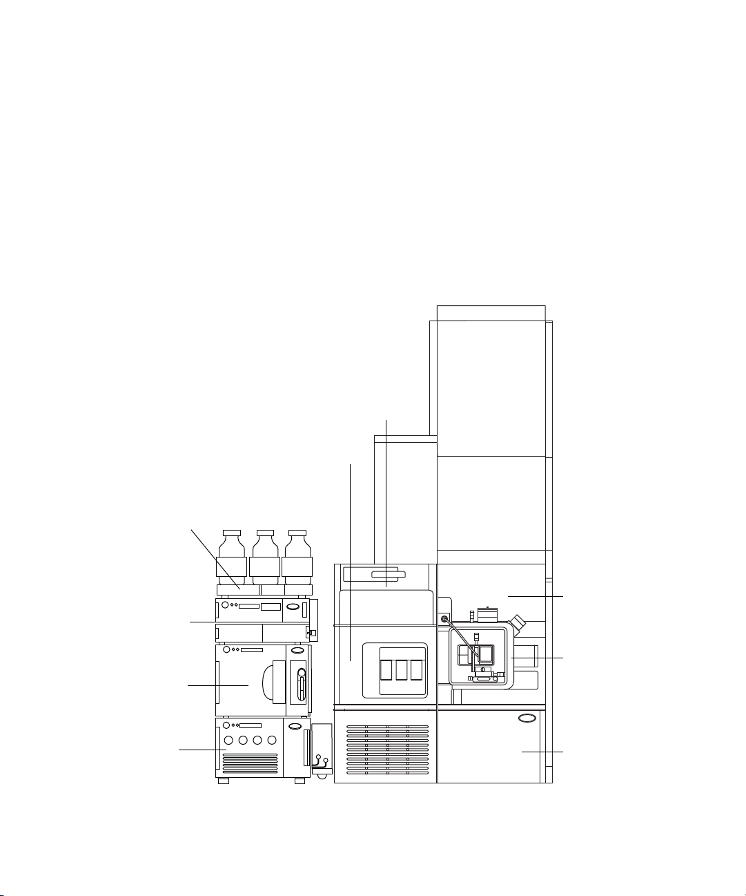
Waters ACQUITY Xevo G2-XS QTof UPLC/MS system:
Sample organizer (optional)
Solvent tray
Xevo G2-XS QTof
Sample manager
Binary solvent manager
Access door to the fluidics pumps
High voltage
connector for the
ESI probe
Probe
Source interface
sliding door
LockSpray source
enclosure
Access door to the
fluidics valves
Column heater
Waters Xevo G2-XS QTof
Note: An ACQUITY UPLC I-Class system is illustrated. See page 26 for
information about other ACQUITY UPLC systems supported by the
Xevo G2-XS QTof.
April 2, 2015, 715004496 Rev. B 27
Page 28
1 Waters Xevo G2-XS QTof Overview
Solvent tray
Trap valve
manager
Xevo G2-XS QTof
µSample
manager
-fixed loop
Access door to the fluidics pumps
Access door to the fluidics valves
Source interface
sliding door
NanoLockSpray
source enclosure
µBinary
solvent
manager
ACQUITY UPLC M-Class system
The ACQUITY UPLC M-Class system includes a binary solvent manager,
auxiliary solvent manager, sample manager, column heater, sample
organizer, detectors, and a specialized ACQUITY UPLC M-Class column.
Waters informatics software controls the system.
For further information, see the ACQUITY UPLC M-Class System Guide (part
number 715003588) and Controlling Contamination in UPLC/MS and
HPLC/MS Systems (part number 715001307). You can find the latter
document on http://www.waters.com; click Services & Support > Support.
Waters ACQUITY M-Class Xevo G2-XS QTof UPLC/MS system:
28 April 2, 2015, 715004496 Rev. B
Page 29

Software and data system
You can use MassLynx software or UNIFI software to control the mass
spectrometer.
Both MassLynx software and UNIFI software enable these major operations:
• Configuring the system
• Creating LC, MS, and MS/MS methods that define operating
parameters for a run
• Using IntelliStart software to automatically tune and mass calibrate the
mass spectrometer
• Running samples
• Monitoring the run
• Acquiring data
• Processing data
•Reviewing data
• Printing data
Waters Xevo G2-XS QTof
MassLynx software
MassLynx software acquires, analyzes, manages, and distributes mass
spectrometry, ultraviolet (UV), evaporative light scattering (ELS), and analog
data. OpenLynx™ and TargetLynx™ application managers are included with
MassLynx software.
See the MassLynx software user documentation and online Help for
information about using MassLynx software.
You configure settings, monitor performance, run diagnostic tests, and
maintain the system and its modules via the MassLynx Instrument Control
application.
The Instrument Control Software, which functions independently of
MassLynx software, does not recognize or control data systems.
See the online Help for the Instrument Console system for further details.
April 2, 2015, 715004496 Rev. B 29
Page 30

1 Waters Xevo G2-XS QTof Overview
UNIFI software
UNIFI software integrates mass spectrometry, UPLC chromotography, and
informatics data workflows into one system.
See UNIFI software user documentation and online Help for more information
about using UNIFI software.
30 April 2, 2015, 715004496 Rev. B
Page 31

LockSpray source and ionization modes
LockSpray source
Solvent tray
LockSpray source and ionization modes
The LockSpray source uses lock-mass correction to acquire exact mass data.
The analyte is introduced into the source through a probe. A reference flow
containing a compound of known mass flows through a separate ESI probe. An
oscillating baffle allows the sprays to be analyzed as two separate data
functions. The lock-mass correction calculated from the reference data is then
applied to the analyte data set.
You can use the LockSpray source with the ESI, APCI, and ESCi ionization
modes (see Chapter 3), and with the ASAP ionization mode (see the
Atmospheric Solids Analysis Probe Operator’s Guide Supplement, part
number 715002034).
Xevo G2-XS QTof fitted with LockSpray source:
April 2, 2015, 715004496 Rev. B 31
Page 32

1 Waters Xevo G2-XS QTof Overview
IonSABRE II probe
Sample cone
Corona pin
Electrospray ionization (ESI)
In ESI, a strong electrical charge is applied to the eluent as it emerges from a
nebulizer. The droplets that compose the resultant aerosol undergo a
reduction in size (solvent evaporation). As solvent continues to evaporate, the
charge density increases until the droplet surfaces eject ions (ion evaporation).
The ions can be singly or multiply charged.
To operate the LockSpray source in ESI mode, you fit the source enclosure
with an ESI probe.
The standard ESI probe capillary accommodates flow rates of up to 2 mL/min,
making it suitable for LC applications in the range of 100 µL/min to 2 mL/min.
To reduce peak broadening for lower flow rate LC applications, such as 1-mm
UPLC columns, use the optional, small-bore capillary, which can
accommodate a maximum flow rate of 200 µL/min.
Atmospheric pressure chemical ionization (APCI)
APCI produces singly charged protonated or deprotonated molecules for a
broad range of nonvolatile analytes.
The APCI interface consists of the ESI/APCI/ESCi enclosure fitted with a
corona pin and an IonSABRE™ II probe. Mobile phase from the LC column
enters the probe, where it is pneumatically converted to an aerosol, rapidly
heated, and vaporized or gasified at the probe tip.
APCI mode:
Hot gas from the IonSABRE II probe passes between the sample cone and the
corona pin, which is typically operated with a discharge current of 5 µA.
Mobile phase molecules rapidly react with ions generated by the corona
discharge to produce stable reagent ions. Analyte molecules introduced into
32 April 2, 2015, 715004496 Rev. B
Page 33

LockSpray source and ionization modes
the mobile phase react with the reagent ions at atmospheric pressure and
typically become protonated (in the positive ion mode) or deprotonated (in the
negative ion mode). The sample and reagent ions then pass through the
sample cone and into the mass spectrometer.
Combined electrospray/atmospheric pressure chemical ionization (ESCi)
In ESCi mode, the standard ESI probe is used in conjunction with a corona
pin. The design allows alternating acquisition of ESI and APCI ionization
data, facilitating high-throughput processing and wider compound coverage.
Atmospheric solids analysis probe (ASAP)
The ASAP facilitates rapid analysis of volatile and semivolatile compounds in
solids, liquids, and polymers. It is particularly suited to analyzing low-polarity
compounds.The ASAP directly replaces the electrospray or IonSABRE II
probe in the instrument’s source housing and has no external gas or electrical
connections.
For further details, see the Atmospheric Solids Analysis Probe Operator’s
Guide Supplement (part number 715002034).
April 2, 2015, 715004496 Rev. B 33
Page 34

1 Waters Xevo G2-XS QTof Overview
NanoLockSpray source and ionization modes
The NanoLockSpray source allows ESI in the flow rate range of
5 to 1,000 nL/min. For a given sample concentration, the ion currents for
similar experiments approximate those in normal flow rate electrospray.
However, because sample consumption is greatly reduced, the sensitivity
gains are significant when you use similar scan parameters.
Lock-mass correction with the NanoLockSpray source works as the LockSpray
source does in ESI mode.
The NanoLockSpray source enclosure consists of a sprayer — universal or
borosilicate glass capillary, (see below) — mounted on a ZSpray three-axis
manipulator.
A light within the source provides illumination for the spray, which you can
observe using the video camera mounted on the corner of the source housing,
(see page 74).
34 April 2, 2015, 715004496 Rev. B
Page 35

NanoLockSpray source and ionization modes
NanoLockSpray source
Solvent tray
Xevo G2-XS QTof fitted with NanoLockSpray source:
Options shown in the following table are available for the spraying capillary.
Spraying capillary options:
Option Description
Universal NanoFlow™
nebulizer sprayer
Borosilicate glass capillary
NanoFlow (nanovials)
For flow injection or coupling to ACQUITY
UPLC M-Class systems. A pump regulates
flow rate to as low as 100 nL/min.
Uses metal-coated glass capillaries,
permitting the lowest flow rates. Usable for
one sample only, after which you must discard
them.
April 2, 2015, 715004496 Rev. B 35
Page 36

1 Waters Xevo G2-XS QTof Overview
Combined APPI/APCI source
Atmospheric pressure photoionization (APPI) uses photons generated by a
discharge UV lamp (~10.2 eV) to produce sample ions from vaporized LC
eluent. Direct photoionization of the sample molecule occurs when the photon
energy exceeds the ionization potential of the sample molecule.
The optional dual-mode (APPI/APCI) ionization source comprises an APPI
source enclosure, which is used in conjunction with a standard APCI probe.
You can operate the source in APPI or dual mode. The latter mode involves
rapid alternation of the APPI and APCI ionization modes, facilitating
high-throughput analyses.
Atmospheric pressure gas chromotography (APGC) source
The Waters APGC couples an Agilent GC with the Xevo G2-XS QTof, making
it possible to perform LC and GC analyses in the same system. The APGC
provides complementary information to the LC/MS instrument, enabling
analysis of compounds of low molecular weight, low-to-intermediate polarity,
or both.
For further details, see the Atmospheric Pressure GC Operator’s Guide
Supplement (part number 715001804).
36 April 2, 2015, 715004496 Rev. B
Page 37

ionKey source
The ionKey source performs UPLC separation inside the source of the mass
spectrometer.
The source precisely positions the iKey™ separation device and integral
emitter in the mass spectrometer. All fluid, electronic connections (heater and
electrospray high voltage), and gas connections (sheath gas) are made inside
the source, eliminating the need to manually connect electronic cables and
tubing.
See the ACQUITY UPLC M-Class System Guide (part number 715003588)
and the ionKey/MS System Guide (part number 715004028) for further
details.
Tip: The ionKey source is also compatible with nanoACQUITY UPLC systems.
See also: “Installing and removing the ionKey source”.
ionKey source
April 2, 2015, 715004496 Rev. B 37
Page 38

1 Waters Xevo G2-XS QTof Overview
IntelliStart Fluidics system
The IntelliStart Fluidics system is built into the instrument and controls how
the system delivers sample to the source. System connections differ according
to whether you use a LockSpray, NanoLockSpray, or ionKey source. See
page 223.
For standard flow applications, the system delivers sample directly to the
mass spectrometer’s source in one of three ways:
• From the LC column.
• From three integral reservoir bottles. Use standard reservoir bottles
(30 mL) for instrument setup and calibration. Use low-volume vials
(1.5 mL) to infuse smaller volumes.
The reservoir bottles can also deliver sample through direct or combined
infusion, permitting optimization at analytical flow rates.
• From a wash reservoir that contains solvent for automated flushing of
the instrument’s solvent delivery system.
For ACQUITY UPLC M-Class, the valves and pumps of the IntelliStart
Fluidics system introduce dead volume, which can cause unacceptable peak
broadening. For this reason, the ACQUITY UPLC M-Class is plumbed directly
to the NanoFlow sprayer using a suitable, short piece of silica tubing.
For reference flows for the LockSpray, NanoLockSpray, or ionKey sources, the
IntelliStart Fluidics system delivers lock-mass solution from reservoir bottle
B or, for extended operating hours, from a separate, external bottle of
lock-mass solution.
38 April 2, 2015, 715004496 Rev. B
Page 39

IntelliStart Fluidics system physical layout
A
B
C
A
B
C
A
B
C
A
B
C
LockSpray selector valve
Sample selector
valve
Diverter valve
Sample pump
LockSpray pump
Sample reservoir bottles (A, B, and C)
Tube guides Optional flow sensor
Grounded union
Access doors
The IntelliStart Fluidics system comprises the components shown in the
following figure.
IntelliStart Fluidics system components:
IntelliStart Fluidics system
April 2, 2015, 715004496 Rev. B 39
Page 40

1 Waters Xevo G2-XS QTof Overview
The IntelliStart Fluidics system consists of these components:
• A sample delivery system composed of a pump, sample selector valve,
and a diverter valve used for LC and probe connections.
• A LockSpray system, composed of a pump capable of ultra-low flow
rates, a LockSpray selector valve, flow sensor, and grounded union. The
grounded union protects the flow sensor from probe voltages. The flow
sensor regulates flow rate, reducing it to accommodate the very low
volumes required by the NanoLockSpray source. The flow sensor and
grounded union are optional fittings for the LockSpray system. They
are, however, standard fittings for the NanoLockSpray source.
• Three shared 30-mL sample reservoir bottles: A, B, and C.
• Plumbing for shared wash and waste bottles.
The sample reservoirs are mounted on the instrument’s front panel. When you
select a solvent in the instrument software, a LED illuminates the
appropriate reservoir. You can simultaneously illuminate all three reservoirs
or extinguish the LEDs, for light-sensitive samples.
Recommendation: Use reservoir A for the sample solution, reservoir B for the
LockSpray solution, and reservoir C for the calibrant solution.
The wash reservoir and (optionally) the reservoirs containing the lock-mass
reference solutions are external to the instrument; typically they are bottles
on the LC system. The waste reservoir is normally a bottle stored under the
instrument bench.
During normal operation, the instrument access doors must be kept closed.
System operation
You configure the IntelliStart Fluidics system using the instrument software,
in which you can edit parameter settings, frequency, and the extent of the
automation. During auto-calibration, the software automatically controls lock
mass and sample delivery.
Consult the mass spectrometer’s online Help for further details about
operating the IntelliStart Fluidics system.
40 April 2, 2015, 715004496 Rev. B
Page 41

Ion optics
The mass spectrometer’s ion optics operate in the following sequence:
1. Samples from the LC or instrument’s solvent delivery system are
introduced at atmospheric pressure into the ionization source.
2. The ions pass through the sample cone and into the vacuum system.
3. The ions pass through the StepWave™ ion guide to the quadrupole,
where they are filtered according to their mass-to-charge ratio.
4. The mass-separated ions pass into the XS Collision Cell, where they can
undergo collision-induced dissociation (CID).
5. The ions, focused by the transfer lenses, pass into the time-of-flight (Tof)
analyzer. A high voltage pulse orthogonally accelerates the ions up the
flight tube, where a reflectron reflects them back toward the detector.
Ions of different mass-to-charge ratios arrive at the detector at different
times. The difference in the arrival times provides the basis for a mass
spectrum.
Ion optics
6. The signal from the detector is amplified, digitized, and transmitted to
the software.
April 2, 2015, 715004496 Rev. B 41
Page 42

1 Waters Xevo G2-XS QTof Overview
Detector
Isolation
valve
LockSpray sprayer
XS Collision Cell
Quadrupole
Tof housing
Reflectron
Sample
cone
pDRE™ lens
StepWave ion guide
Sample sprayer
Pusher
To vacuum pump
To vacuum pumps
Transfer lenses
Ion optics overview:
42 April 2, 2015, 715004496 Rev. B
Page 43

Leak sensors
Leak sensors in the instrument’s drip trays continuously monitor for liquid
leaks. A leak sensor stops all solvent flow when it detects approximately
1.5 mL of accumulated leaked liquid in the reservoir that surrounds it. At the
same time, the Instrument Console or UNIFI software displays an error
message alerting you that a leak has developed.
Consult the Waters ACQUITY UPLC Leak Sensor maintenance instructions
(part number 71500082506) for complete details.
Vacuum system
An external roughing pump and three internal turbomolecular pumps
maintain the required vacuum.
Protective interlocks guard against vacuum leaks and electrical or vacuum
pump failure. The system monitors the turbomolecular pump speeds and
continuously measures vacuum pressure via built-in gauges. The gauges also
serve as switches, stopping operation when vacuum loss is sensed.
Leak sensors
A vacuum isolation valve isolates the source from the mass analyzer, allowing
cleaning of the sample cone without the need to vent the instrument to
atmospheric pressure.
April 2, 2015, 715004496 Rev. B 43
Page 44

1 Waters Xevo G2-XS QTof Overview
44 April 2, 2015, 715004496 Rev. B
Page 45

2 Preparing the Mass
Spectrometer for Operation
This chapter explains how to start up and shut down the mass
spectrometer.
Contents:
Topic Page
Starting the mass spectrometer ...................................................... 46
Preparing the IntelliStart Fluidics system..................................... 49
Rebooting the mass spectrometer ................................................... 53
Leaving the mass spectrometer ready for operation...................... 54
Emergency shutdown of the mass spectrometer............................ 54
April 2, 2015, 715004496 Rev. B 45
Page 46

2 Preparing the Mass Spectrometer for Operation
Starting the mass spectrometer
The Waters Xevo G2-XS QTof is compatible with several types of ACQUITY
UPLC systems. See page 26 for details of which ACQUITY UPLC systems are
compatible. If you do not use one of these systems, refer to the documentation
for your LC system.
Notice: To avoid damage to the instrument caused by incompatible
solvents, refer to the following sources:
• Appendix C, page 303, for mass spectrometer solvent information.
• The relevant ACQUITY UPLC system operator’s guide or system
guide, for solvent compatibility with ACQUITY devices.
Requirement: Turn on the instrument server or workstation PC first, to
ensure that it can assign IP addresses to LCMS system modules.
See the mass spectrometer’s online Help for details.
To start the mass spectrometer:
1. On the rear panel, ensure the nitrogen supply is connected to the
instrument’s nitrogen inlet connection (see the figure on page 284).
Requirement: The nitrogen must be dry and oil-free, with a purity of at
least 95%. Regulate the supply at 6.5 to 7.0 bar, (94 to 102 psi).
2. Ensure that the collision-gas supply is connected to the instrument’s
collision cell gas inlet (see the figure on page 284).
Requirement: The collision gas is argon; it must be dry and of high
purity (99.997%). Regulate the supply at 50 kPa (0.5 bar, 7 psi).
3. Turn on the instrument server or workstation PC.
4. Power-on the Xevo G2-XS QTof at the power outlet.
5. Power-on the ACQUITY instruments.
Result: Each system component runs a series of startup tests.
46 April 2, 2015, 715004496 Rev. B
Page 47

Starting the mass spectrometer
6. Allow 4 minutes for the PC to initialize.
Tip: The power and status LEDs change as follows:
• During initialization, the binary solvent manager’s and sample
manager’s status LED flashes green.
• After the instruments successfully power-on, all power LEDs show
steady green. The binary solvent manager’s flow LED, the sample
manager’s run LED, and the mass spectrometer’s status LED
remain unlit.
7. Start the software, and monitor the Instrument Console or UNIFI
software for messages and LED indications.
8. Click Operate (if using MassLynx software), or Instrument Operate
Mode (if using UNIFI software).
Result: When the mass spectrometer is in good operating condition,
IntelliStart software displays “Ready” in the Instrument Console;
UNIFI software displays the status “Running” in the Instrument
Summary pane.
Notice: To avoid damaging the iKey separation device (where fitted), set
the capillary voltage to zero when you leave the mass spectrometer in
Operate mode and solvent is not flowing.
April 2, 2015, 715004496 Rev. B 47
Page 48

2 Preparing the Mass Spectrometer for Operation
Verifying the instrument’s state of readiness
When the mass spectrometer is in good operating condition, the power and
status LEDs show constant green. You can view any error messages in the
IntelliStart software (MassLynx), or the UNIFI software.
Monitoring the mass spectrometer LEDs
LEDs on the mass spectrometer indicate its operational status.
Power LED – The power LED, below the mass spectrometer’s source, indicates
when the mass spectrometer is powered-on or powered-off.
Status LED – The status LED, on the right-hand side of the power LED,
indicates the operating condition.
Status information from the front of the instrument:
Status LED Instrument State
Off Standby
Green Operate
Amber Source Standby
Flashing Green Operate with pump override on
Flashing Amber Standby with pump override on
Flashing Red Not at vacuum
Red RF Trip
Calibration
Calibrate the mass spectrometer prior to use. See the mass spectrometer’s
online Help for details.
48 April 2, 2015, 715004496 Rev. B
Page 49

Preparing the IntelliStart Fluidics system
Flow rates for the Xevo G2-XS QTof system
The Xevo G2-XS QTof system can run at high flow rates. To optimize
desolvation, and thus sensitivity, run the system at appropriate gas flows and
desolvation temperatures.
Flow rate versus temperature and gas flow:
Flow rate
(mL/min)
<0.021 100 200 800
0.021 to 0.100 120 350 800
0.101 to 0.300 120 450 800
0.301 to 0.500 150 500 1,000
>0.500 150 600 1,200
Source
temperature (°C)
Desolvation
temperature (°C)
Preparing the IntelliStart Fluidics system
For additional information, see page 38.
Warning: To avoid injuries from broken glass, falling objects, or
exposure to toxic substances, do not place containers on top of the
instrument or on its front covers. Instead use the bottle tray.
Installing the reservoir bottles
Use standard reservoir bottles (30 mL) for instrument setup and calibration.
Use the Low-volume Adaptor Kit (included) to infuse smaller volumes. The
low-volume vials have a volume of 1.5 mL.
Desolvation gas
flow (L/h)
Required materials
Chemical-resistant, powder-free gloves
April 2, 2015, 715004496 Rev. B 49
Page 50

2 Preparing the Mass Spectrometer for Operation
Reservoir bottle
Solvent delivery tube
To install the reservoir bottles:
Warning: To avoid personal contamination with biologically
hazardous, toxic, or corrosive materials, and to avoid
spreading contamination to uncontaminated surfaces, wear
clean, chemical-resistant, powder-free gloves when working
with the reservoir bottles.
1. Remove the reservoir bottle caps.
2. Screw each onto the mass spectrometer, as shown below.
3. For each reservoir bottle, ensure that the ends of the solvent delivery
tubes are close to, but do not touch, the bottom of the bottle (see
page 52).
50 April 2, 2015, 715004496 Rev. B
Page 51

Preparing the IntelliStart Fluidics system
Low-volume vial
Low-volume adaptor
Solvent delivery tube
To install the low-volume vials:
Warning: To avoid personal contamination with biologically
hazardous, toxic, or corrosive materials, and to avoid
spreading contamination to uncontaminated surfaces, wear
clean, chemical-resistant, powder-free gloves when working
with the reservoir bottles.
1. If a standard reservoir bottle is fitted, remove it.
2. Screw each low-volume adaptor into the manifold and finger-tighten it.
Warning: To avoid laceration injuries caused by the shattering of
fragile, low-volume glass vials, take care when screwing them in,
and never use force.
3. Screw each low-volume vial into the adaptor.
4. For each low-volume vial, ensure that the ends of the solvent delivery
tubes are close to, but do not touch, the bottom of the vial (see page 52).
April 2, 2015, 715004496 Rev. B 51
Page 52

2 Preparing the Mass Spectrometer for Operation
Finger-tight fitting
Solvent delivery tube
Adjusting the solvent delivery tube positions
For correct operation of the IntelliStart Fluidics system, you must adjust each
solvent delivery tube so that its end is close to, but does not touch, the bottom
of the reservoir bottle or low-volume vial.
To adjust the position of a solvent delivery tube:
1. Open the access door to the fluidics pumps (see the figure on page 28).
2. Loosen the finger-tight fitting for the solvent delivery tube you are
adjusting.
3. Position the solvent delivery tube so that its end is close to, but does not
touch, the bottom of the reservoir bottle or low-volume vial.
4. Tighten the finger-tight fitting.
5. Close the access door.
52 April 2, 2015, 715004496 Rev. B
Page 53

Purging the pump
Each time you replace a solution bottle, you must purge the pump with the
solution that you are going to use next. See the mass spectrometer’s online
Help for details.
Requirement: Ensure that the end of the tubing is fully submerged in the
solvent in the wash reservoir.
Tip: Depending on the solutions that you use, the system can require more
than one purge cycle to minimize carryover.
Rebooting the mass spectrometer
Reboot the mass spectrometer when one of these conditions apply:
• The console software fails to initialize or connect.
• Immediately following a software upgrade.
To reboot the mass spectrometer:
Rebooting the mass spectrometer
1. If you are using MassLynx software, exit the application.
Note: If you are using UNIFI software, you can leave it running while
you reboot the mass spectrometer.
2. Open the sliding door above the instrument’s source enclosure, and
locate the reset button aperture.
3. Insert a short length of PEEK™ tubing into the aperture to press the
reset button.
April 2, 2015, 715004496 Rev. B 53
Page 54

2 Preparing the Mass Spectrometer for Operation
Leaving the mass spectrometer ready for operation
When you are not using the instrument, stop the LC flow, and put the
instrument in Source Standby mode, to conserve energy and reduce nitrogen
consumption (see the online Help for details).
Tip: After you return the instrument to Operate mode, the LockSpray source’s
temperature requires up to 30 minutes to stabilize at the relatively high
temperatures needed for UPLC operation.
Notice: To avoid damaging the iKey separation device (where fitted), set
the capillary voltage to zero when you leave the mass spectrometer in
Operate mode and solvent is not flowing.
Emergency shutdown of the mass spectrometer
To shut down the mass spectrometer in an emergency:
Warning: To avoid electric shock, isolate the instrument from the
electrical supply by disconnecting the power cable from the instrument’s
rear panel.
Note: Data can be lost during an emergency shutdown.
1. Switch off the power at the electrical outlet.
Result: The instrument shuts down and vents.
2. Disconnect the power cable from the instrument’s rear panel.
54 April 2, 2015, 715004496 Rev. B
Page 55

3 Configuring the LockSpray
Source
This chapter explains how to configure the LockSpray source for the
following ionization modes:
• ESI (electrospray ionization)
• APCI (atmospheric pressure ionization)
• ESCi (combined electrospray and atmospheric pressure ionization)
Contents:
Topic Page
Configuring the LockSpray source.................................................. 56
Configuring for ESI mode................................................................ 57
Configuring for APCI mode ............................................................. 62
Configuring for ESCi mode.............................................................. 66
April 2, 2015, 715004496 Rev. B 55
Page 56

3 Configuring the LockSpray Source
Configuring the LockSpray source
The following table summarizes how you configure the LockSpray source for
the various ionization modes.
Configuring the LockSpray source:
Ionization mode Probe type Corona pin fitted?
ESI ESI No
APCI APCI Yes
ESCi ESI Yes
56 April 2, 2015, 715004496 Rev. B
Page 57

Configuring for ESI mode
To operate in ESI mode, you must fit the ESI probe to the LockSpray source
enclosure.
For more information about using ESI mode, see the Xevo G2-XS QTof system
online Help.
Installing the ESI probe
Required materials
• Chemical-resistant, powder-free gloves
• Sharp knife or PEEK tubing cutter
To install the ESI probe:
Warning: To avoid personal contamination with biologically
hazardous, toxic, or corrosive materials, and to avoid
spreading contamination to uncontaminated surfaces, wear
clean, chemical-resistant, powder-free gloves when working
with the LC system connections, ESI probe, and source.
Configuring for ESI mode
Warning: To avoid electric shock, ensure that the instrument is
prepared for working on the source before commencing this procedure.
1. Prepare the instrument for working on the source (see page 99).
Warning: To avoid puncture wounds, handle the probe with care.
2. Remove the protective sleeve, if fitted, from the ESI probe tip.
April 2, 2015, 715004496 Rev. B 57
Page 58

3 Configuring the LockSpray Source
TP03129
Location hole of the probe adjuster assembly
Probe location dowel
Probe label
3. With the probe label facing you, carefully slide the ESI probe into the
hole in the probe adjuster assembly, ensuring that the probe location
dowel aligns with the location hole in the probe adjuster assembly.
58 April 2, 2015, 715004496 Rev. B
Page 59

Configuring for ESI mode
TP03128
ESI high voltage cable
ESI probe
Vernier probe adjuster
Probe locking ring
Source window
Source enclosure
release
ESI probe, mounted on the LockSpray source enclosure:
Warning: To avoid nitrogen leakage, fully tighten the probe
locking ring.
4. Tighten the probe locking ring to secure the probe in place.
Tip: An automatic pressure test is performed when the probe is correctly
seated in position.
5. Connect the ESI probe’s cable to the high voltage connector.
6. Open the access door to the fluidics valves (see the figure on page 28).
Warning: To avoid electric shock, do not use stainless steel tubing
to connect the diverter valve to the ESI probe; use the PEEK
tubing supplied with the instrument.
7. Using a long finger-tight fitting, connect 0.004-inch ID (or greater)
tubing, from port 2 (the top port) of the diverter valve to the ESI probe.
April 2, 2015, 715004496 Rev. B 59
Page 60

3 Configuring the LockSpray Source
ESI probe
Diverter valve
Tubing connection
Probe adjuster
assembly
8. Secure the union with a PEEK finger-tight nut and ferrule.
Recommendation: To reduce peak broadening, use 0.004-inch ID tubing
for sample flow rates ≤1.2 mL/min; use 0.005-inch ID tubing for sample
flow rates >1.2 mL/min.
Requirements:
• If you are replacing the tubing supplied with the instrument, you
must minimize the length of the tube connecting the diverter valve
to the ESI probe. Doing so minimizes delays and dispersion.
• When cutting the tubing to length, cut it squarely (that is,
perpendicular to its horizontal axis).
Long finger-tight fitting and PEEK, finger-tight nut and ferrule:
Warning: To avoid electric shock, only use natural (beige) PEEK
fittings at the top of the probe.
9. Close the access door to the fluidics valves.
60 April 2, 2015, 715004496 Rev. B
Page 61

Removing the ESI probe
Required materials
Chemical-resistant, powder-free gloves
To remove the ESI probe:
Warning: To avoid personal contamination with biologically
hazardous, toxic, or corrosive materials, and to avoid
spreading contamination to uncontaminated surfaces, wear
clean, chemical-resistant, powder-free gloves when working
with the LC system connections, ESI probe, and source.
Warning: To avoid electric shock, ensure that the instrument is
prepared for working on the source before commencing this procedure.
1. Prepare the instrument for working on the source (see page 99).
2. Disconnect the fluidics tubing from the ESI probe.
Configuring for ESI mode
3. Disconnect the ESI probe’s cable from the high voltage connector.
4. Unscrew the probe locking ring.
Warning: To avoid puncture wounds, handle the probe with care.
5. Carefully remove the ESI probe from the probe adjuster assembly.
6. If available, fit the protective sleeve to the ESI probe tip.
April 2, 2015, 715004496 Rev. B 61
Page 62

3 Configuring the LockSpray Source
Configuring for APCI mode
To operate in APCI mode, you must fit the IonSABRE II probe to the
LockSpray source enclosure.
For more information on using APCI mode, see the Xevo G2-XS QTof system
online Help.
Installing the IonSABRE II probe
Required materials
• Chemical-resistant, powder-free gloves
• Sharp knife or PEEK tubing cutter
To install the IonSABRE II probe:
Warning: To avoid personal contamination with biologically
hazardous, toxic, or corrosive materials, and to avoid
spreading contamination to uncontaminated surfaces, wear
clean, chemical-resistant, powder-free gloves when working
with the LC system connections, IonSABRE II probe, and
source.
Warning: To avoid electric shock, ensure that the instrument is
prepared for working on the source before commencing this procedure.
62 April 2, 2015, 715004496 Rev. B
Page 63

Configuring for APCI mode
TP03129
Probe location dowel
Probe adjuster assembly
location hole
Probe label
1. Prepare the instrument for working on the source (see page 99).
2. With the probe label facing you, carefully slide the IonSABRE II probe
into the hole in the probe adjuster assembly, ensuring that the probe
location dowel aligns with the probe adjuster assembly location hole.
April 2, 2015, 715004496 Rev. B 63
Page 64

3 Configuring the LockSpray Source
TP03128
Vernier probe
adjuster
Source enclosure
release
Source window
IonSABRE II probe
3. Tighten the probe locking ring to secure the probe in place.
Tip: An automatic pressure test is performed when the probe is correctly
seated in position.
IonSABRE II probe mounted on the source enclosure:
64 April 2, 2015, 715004496 Rev. B
4. Open the access door to the fluidics valves (see the figure on page 28).
Warning: To avoid electric shock, do not use stainless steel tubing
to connect the diverter valve to the IonSABRE II probe; use the
PEEK tubing supplied with the instrument.
Page 65

5. Using tubing ≥ 0.004-inch ID, connect port 2 (the top port) of the diverter
valve to the IonSABRE II probe.
Recommendation: To reduce peak broadening, use 0.004-inch ID tubing
for sample flow rates ≤1.2 mL/min; use 0.005-inch ID tubing for sample
flow rates >1.2 mL/min.
Requirements:
• If you are replacing the tubing supplied with the instrument, you
must minimize the length of the tube connecting the diverter valve
to the IonSABRE II probe. Doing so minimizes delays and
dispersion.
• When cutting the tubing to length, cut it squarely (that is,
perpendicular to its horizontal axis).
6. Close the access door.
7. Install the corona pin (see page 103).
Removing the IonSABRE II probe
Configuring for APCI mode
Required materials
Chemical-resistant, powder-free gloves
To remove the IonSABRE II probe:
Warning: To avoid personal contamination with biologically
hazardous, toxic, or corrosive materials, and to avoid
spreading contamination to uncontaminated surfaces, wear
clean, chemical-resistant, powder-free gloves when working
with the LC system connections, ESI probe, and source.
Warning: To avoid electric shock, ensure that the instrument is
prepared for working on the source before commencing this procedure.
1. Prepare the instrument for working on the source (see page 99).
2. Remove the corona pin (see page 103).
3. Disconnect the diverter valve tubing from the IonSABRE II probe.
4. Unscrew the probe locking ring.
5. Carefully remove the probe from the probe adjuster assembly.
April 2, 2015, 715004496 Rev. B 65
Page 66

3 Configuring the LockSpray Source
Configuring for ESCi mode
To operate the instrument in ESCi mode, you must fit an ESI probe and
corona pin to the LockSpray source enclosure, (see page 33, page 61, and
page 103).
The system, with the ESI probe installed and corona discharge pin fitted, can
alternate between ESI and ESCi modes, facilitating data acquisition in ESI
and ESCi modes in parallel. For more information on using dual ESI and
ESCi modes, see the Xevo G2-XS QTof system online Help.
Optimizing the ESI probe for ESCi operation
See the mass spectrometer’s online Help for instructions explaining how to
optimize the ESI probe for ESCi operation.
66 April 2, 2015, 715004496 Rev. B
Page 67

4 Configuring the NanoLockSpray
Source
The NanoLockSpray electrospray ion-source enables the optimized
co-introduction of sample and lock-mass compound directly into the ion
source. At low flow rates, this feature provides authenticated,
exact-mass measurement in both MS and MS/MS modes.
Contents:
Topic Page
Overview of the NanoLockSpray source ......................................... 68
Selecting and configuring the NanoLockSpray source .................. 71
Deploying the sprayer platform adjuster assembly ....................... 72
Adjusting the sprayer tip position................................................... 73
Setting up the camera...................................................................... 74
Optional glass-capillary sprayer ..................................................... 75
April 2, 2015, 715004496 Rev. B 67
Page 68

4 Configuring the NanoLockSpray Source
Sprayer-platform adjuster assembly
Thumbscrew
Thumbscrew (on left-hand
side of sprayer platform)
Sprayer safety cover
Z-position adjuster
Y-position adjuster
X-position adjuster
LockSpray sprayer inlet
Camera focusing ring
Camera
Clear sprayer shield
Shield
holding screw
NanoLockSpray reference probe
Clear
sprayer shield
Baffle-motor housing
Overview of the NanoLockSpray source
NanoLockSpray source:
The NanoLockSpray source enclosure holds two NanoFlow sprayers
positioned orthogonally, with respect to one another. The sample flows
through one sprayer, and the lock-mass reference solution flows through the
other sprayer. A motorized baffle rotates to admit spray from each sprayer
into the sampling cone.
68 April 2, 2015, 715004496 Rev. B
Page 69

Schematic of the NanoLockSpray source:
LockSpray inlet
Sample inlet
Sample cone
Baffle
Overview of the NanoLockSpray source
Spray indexing permits acquisition of sample and LockSpray data in separate
data channels, and the baffle design ensures negligible cross-talk between the
two sprays. The LockSpray data are used to calculate a correction factor for
the mass-scale calibration, which is then applied to the sample data, providing
exact-mass information.
Sample sprayer
You can use the NanoLockSpray source with different NanoFlow sprayers.
For instructions explaining how to set up the sprayers, see page 71.
LockSpray sprayer
The LockSpray sprayers for the NanoLockSpray source operate as part of the
instrument's IntelliStart Fluidics system. The LockSpray sprayer is fitted
with a 500 µL pump, and operates at 0.5 µL/min.
You must choose the concentration of the LockSpray reference solution that
gives a suitable ion intensity. Refer to the section on selecting and configuring
the NanoLockSpray source (page 71).
April 2, 2015, 715004496 Rev. B 69
Page 70

4 Configuring the NanoLockSpray Source
NanoFlow gas supply
The supply pressure for nebulizer gas flowing to the sample sprayer is
electronically controlled, from 0 bar to 2 bar. The optimum pressure is
sprayer-dependent, but typically lies between 0.3 bar and 1.0 bar.
Purge gas
Purge gas typically flows at 350 L/h. It provides a positive pressure in the
source enclosure that reduces the chemical background interference caused by
contaminants in the laboratory air. For information on adjusting the purge
gas flow, see the mass spectrometer’s online Help.
Sprayer platform adjuster assembly
The sprayer platform adjuster assembly allows precise X, Y, and Z positioning
of the sprayer tip. You can withdraw the sprayer from the source to obtain
access to the sprayer tip.
Using the two thumbscrews on the base of the adjuster assembly, you can
move the platform in and out of the source (see page 72).
70 April 2, 2015, 715004496 Rev. B
Page 71

Selecting and configuring the NanoLockSpray source
Selecting and configuring the NanoLockSpray source
The Universal NanoFlow sprayer is installed as standard equipment on the
NanoLockSpray source. For installation and maintenance details, see the
Waters Universal NanoFlow Sprayer Installation and Maintenance Guide
(part number 71500110107).
When fitted, the NanoLockSpray source is automatically recognized by the
software.
Requirement: The sprayer platform must be inserted in the source enclosure
for correct identification of the source.
The following table summarizes how you configure the NanoLockSpray source
for the various ionization modes.
Tip: A corona pin is not used with the NanoLockSpray source.
NanoLockSpray source configuration:
Sprayer type Description
Universal NanoFlow sprayer. See
Universal NanoFlow Sprayer
Installation and Maintenance Guide,
(part number 71500110107)
Borosilicate glass capillary
NanoFlow (see page 75). For details,
see the Borosilicate Glass Capillary
Sprayer Operator’s Guide (part
number 715003371).
For coupling to ACQUITY UPLC
M-Class with regulated flow rates as
low as 100 nL/min.
Suitable for single-shot analyses.
This option yields lower flow rates
(<30 nL/min) than the universal
sprayer and hence a smaller sample
consumption for a given spectral
quality.
April 2, 2015, 715004496 Rev. B 71
Page 72

4 Configuring the NanoLockSpray Source
Deploying the sprayer platform adjuster assembly
To move the sprayer platform out of the source:
Warning: To avoid electrical shock, ensure the safety cover is in place
over the sprayer.
1. Install the sprayer's safety cover, if necessary (see the figure on
page 68).
2. Unscrew the thumbscrew on the front of the sprayer platform.
3. Pull out the Thumbscrew (on left-hand side of sprayer platform), and
slide the sprayer platform away from the source.
4. Release the side thumbscrew, to lock the platform in the deployed
position.
To move the sprayer platform into the source:
Warning: To avoid electrical shock, ensure the safety cover is in place
over the sprayer.
1. Confirm that the clear sprayer shield is in place and secured (see the
figure on page 68).
2. Confirm that the sprayer’s safety cover is installed.
3. Pull out the thumbscrew on the front of the sprayer platform, to secure,
and push the sprayer platform into the source.
4. Release the side thumbscrew, to lock the platform in position.
5. Tighten the front thumbscrew, securing the adjuster assembly rigidly to
the source.
72 April 2, 2015, 715004496 Rev. B
Page 73

Adjusting the sprayer tip position
To adjust the tip position:
1. Using the X-, Y-, and Z-position adjuster controls on the adjuster
assembly, move the sample-sprayer tip close to the sampling cone and
baffle (see the photo on page 74).
2. Move the sprayer so that its tip is level with the center of the sampling
cone.
Tip: Use the index mark on the adjuster to obtain the correct position.
3. Move the sprayer horizontally, so that the tip points toward the
left-hand side of the baffle.
Tips:
• If you observe an electrical discharge between the sprayer tip and
baffle, move the tip farther from the baffle, or reduce the capillary
voltage. Note, however, that the capillary voltage must be high
enough to maintain a good spray.
Adjusting the sprayer tip position
• Fine-tune the position of the sprayer while acquiring a spectrum of
a standard compound. Small adjustments to the sprayer position
can make large differences to the source sensitivity.
April 2, 2015, 715004496 Rev. B 73
Page 74

4 Configuring the NanoLockSpray Source
Sample cone
Baffle
Sprayer tip
Sample sprayer
Setting up the camera
To set up the camera:
1. Click , to open the Camera Control dialog box.
Camera Control view of sprayers and sample cone:
2. To focus on the sample sprayer, rotate the camera’s focusing ring (see
the figure on page 68).
74 April 2, 2015, 715004496 Rev. B
Page 75

Optional glass-capillary sprayer
The glass-capillary sprayer is designed for use with metal-coated borosilicate
glass capillaries. The glass capillaries allow extremely low flow rates (less
than 100 nL/min). You only use the glass capillaries for one sample, and then
must discard them.
To use the glass-capillary sprayer, complete the procedures described in the
Borosilicate Glass Capillary Sprayer Operator’s Guide (part number
715003371).
Optional glass-capillary sprayer
April 2, 2015, 715004496 Rev. B 75
Page 76

4 Configuring the NanoLockSpray Source
76 April 2, 2015, 715004496 Rev. B
Page 77

5 Installing and removing the
ionKey source
The ionKey source performs UPLC separation inside the source of the mass
spectrometer. (See “ionKey source” on page 37.) For further information, see
the ACQUITY UPLC M-Class System Guide (part number 715003588) and the
ionKey/MS System Guide (part number 715004028).
Contents:
Topic Page
Installing the ionKey source............................................................ 78
Installing ionKey source software................................................... 87
Installing the camera in the ionKey source.................................... 87
Removing the ionKey source ........................................................... 88
April 2, 2015, 715004496 Rev. B 77
Page 78

5 Installing and removing the ionKey source
iKey-separation-device
docking port
Microscope
camera
iKey-separation-device
locking/unlocking handle
Front cover
Reference probe
Installing the ionKey source
The ionKey source enclosure comprises the iKey-separation-device docking
port, the iKey-separation-device locking handle, a reference probe, and a
microscope camera. In addition, a replacement infill panel and a cable
management bracket are provided, to guide the fluid lines for the ionKey
source.
ionKey source:
78 April 2, 2015, 715004496 Rev. B
Required materials
• Chemical-resistant, powder-free gloves
•Screwdriver
• ¼-inch wrench
Page 79

Installing the ionKey source
Warning: To avoid personal contamination with biohazards or
toxic materials, and to avoid spreading contamination to
uncontaminated surfaces, wear clean, chemical-resistant,
powder-free gloves while performing this procedure. The source
components can be contaminated.
Warning: To avoid electric shock, prepare the instrument for work
performed on its source before beginning this procedure.
To install the ionKey source:
1. Prepare the instrument for working on the source (see page 99).
Warning: To avoid burn injuries, take great care while working
with the probe and source; these components can be hot.
2. Remove the probe from the currently installed source:
• If you are removing an ESI probe, see page 61.
• If you are removing an IonSABRE II probe, see page 65.
3. Remove the existing source enclosure (see page 100).
4. Open the access doors to the IntelliStart Fluidics system.
April 2, 2015, 715004496 Rev. B 79
Page 80

5 Installing and removing the ionKey source
A
B
C
A
B
C
A
B
C
A
B
C
Infill panel
Onboard fluidics panel
Thumbscrews
5. Loosen the two thumbscrews that secure the infill panel to the onboard
fluidics panel.
80 April 2, 2015, 715004496 Rev. B
6. Remove the infill panel from the instrument, and store it in a safe
location.
Page 81

Installing the ionKey source
Cable management
bracket
Vertical cutout
7. Fit the cable management bracket to the instrument, as follows:
a. Position the cable management bracket so that the vertical cutout is
aligned with the upper and lower tabs on the instrument.
b. Partially insert the upper-right section of the bracket into the
corresponding slot in the instrument.
c. Carefully push the bracket into place.
Tip: When aligned correctly, the cable management bracket snaps
into position as you push it toward the instrument.
8. Remove the two thumbscrews from the replacement infill panel provided
with the ionKey source.
9. Position the replacement infill panel above the onboard fluidics panel,
and secure the panels to each other using the thumbscrews removed in
step 8.
April 2, 2015, 715004496 Rev. B 81
Page 82

5 Installing and removing the ionKey source
Thumbscrew
Infill panel
Onboard fluidics
panel
Requirement: The thumbscrews must be installed with the screw thread
uppermost, as shown in the following figure.
10. Using two hands, fit the ionKey source enclosure to the two supporting
studs on the source adaptor housing.
11. Swing the source enclosure to the closed position, ensuring it locks into
place.
12. Quit the MassLynx software.
Notice: To avoid damaging the ionKey source or mass spectrometer,
• ensure the µSample manager is powered-off before connecting the
data/power cable;
• ensure that the mass spectrometer is in Standby mode.
13. Power-off the sample manager, and ensure that the mass spectrometer
is in Standby mode.
82 April 2, 2015, 715004496 Rev. B
Page 83

ionKey source connections:
Data/power cable
to PSPI connector
on µSample
manager
Fluid infusion line
Fluid waste line
High voltage cable
Options cable
Fluid inlet line
Reference-probe
high voltage cable
Optional post-column addition (PCA) line
Installing the ionKey source
14. Connect the data/power cable to the PSPI connector on the rear of the
µSample manager, and use a screwdriver to firmly tighten the connector
screws.
April 2, 2015, 715004496 Rev. B 83
Page 84

5 Installing and removing the ionKey source
Data/power
cable to PSPI
connector on
µSample
manager
High voltage
cable
Options
cable
Reference-probe
high voltage cable
Source connections to mass spectrometer:
15. Connect the high voltage cable (white) to the high voltage supply outlet
on the mass spectrometer.
16. Connect the reference-probe high voltage cable (green) to the
reference-probe power inlet on the mass spectrometer.
17. Connect the options cable (blue) to the options port on the mass
84 April 2, 2015, 715004496 Rev. B
spectrometer.
TP03576
Page 85

Installing the ionKey source
Fluid-line aperture
Aperture closed
Aperture open
(spring-loaded)
18. Identify each fluid line by the part numbers printed on its shrink-wrap
tubing.
ionKey tubing assemblies:
Part Number Description
430003899 Infusion line
430003901 Inlet line
430004126 Waste line
430004476 Optional, post-column addition (PCA) line
19. Guide each fluid line through the fluid-line aperture.
Fluid line aperture:
Tip: In the following steps, when connecting the fluid lines for the
ionKey source, use the cable management bracket to guide the fluid
lines. Doing so helps to keep the fluidics plumbing tidy.
April 2, 2015, 715004496 Rev. B 85
Page 86

5 Installing and removing the ionKey source
Fluid-inlet line connected
to injection valve port 6
µSample manager injection valve:
20. Connect the fluid-inlet line to port 6 on the injection valve of the
µSample manager.
21. Connect the fluid-infusion line to port 2 on the diverter valve of the mass
spectrometer.
22. Connect the optional post-column addition (PCA) line to outlet B on the
Auxiliary Solvent Manager (ASM) Flow Control Module.
23. Connect the waste line to a suitable waste container.
24. Connect the reference-probe PEEK capillary to the grounded union
(which is connected to the reference valve on the mass spectrometer).
Rationale: Doing so provides lock-spray operation for the onboard
IntelliStart fluidics.
25. Close the IntelliStart Fluidics system access doors.
26. Power-on the sample manager.
27. Restart the MassLynx software.
See also: ACQUITY UPLC M-Class System Guide (part number 715003588).
86 April 2, 2015, 715004496 Rev. B
Page 87

Installing ionKey source software
Installing ionKey source software
If you are installing an ionKey source on your Xevo G2-XS QTof for the first
time, you must install the appropriate MassLynx software SCN and the
ACQUITY M-Class driver pack. For details, see the following documents:
• ACQUITY UPLC M-Class Driver Pack Installation and Configuration
Guide (part number 715003588) for detailed installation procedures and
instructions explaining how to use the ACQUITY Inlet Switch Utility.
• MassLynx software v4.1 and related SCN release notes for detailed
instructions explaining how to install MassLynx software and SCNs.
Installing the camera in the ionKey source
To install the camera in the ionKey source:
1. Connect the camera cable from the video output connector on the mass
spectrometer’s rear panel to the video-to-USB converter box.
2. Connect the video-to-USB converter box to a USB port on the mass
spectrometer’s workstation.
3. In the Tune window, click Camera Viewer .
4. In the Device Settings dialog box, specify the parameter settings
according to the following table, and then click OK.
Tip: After you install the camera software, when you select the ionKey
camera viewer for the first time, the Device Settings dialog box opens.
To subsequently open the dialog box, in the camera viewer, click View >
Camera Options.
Device settings for the camera:
Parameter Setting
Video norm PAL_B
Video format Y800 (768 x 576)
Frame rate (FPS) 25
Input channel 00 Video: Composite
April 2, 2015, 715004496 Rev. B 87
Page 88

5 Installing and removing the ionKey source
Removing the ionKey source
You can remove the ionKey source, and replace it with a conventional
interface.
Alternative: If you are using the ionKey source with an ACQUITY UPLC
M-Class system mounted on an M-Class cart fitted with an ionKey source
holder, you can secure the source enclosure to the holder. Doing so keeps the
enclosure close to the Xevo G2-XS, for when it is next needed; assists with
managing the ionKey source’s fluid lines; and helps prevent contamination of
the fluid lines.
See the ACQUITY M-Class documentation for further information about
installing the ionKey source holder on the M-Class cart, and securing the
source enclosure to the holder.
Recommendation: The ionKey source is installed along with a
cable-management bracket and a replacement infill panel. You can leave the
bracket and infill panel in place when you replace the ionKey source with a
conventional interface. If, however, you choose to remove the bracket and
replace the original infill panel, reverse the installation instructions (step 5 to
step 9) in “Installing the ionKey source” on page 78.
See also: “Installing the ionKey source” on page 78.
Required materials
• Chemical-resistant, powder-free gloves
• ¼-inch wrench
Warning: To avoid personal contamination with biohazards or
toxic materials, and to avoid spreading contamination to
uncontaminated surfaces, wear clean, chemical-resistant,
powder-free gloves while performing this procedure. The source
components can be contaminated.
Warning: To avoid electric shock, prepare the instrument for work
performed on its source before beginning this procedure.
88 April 2, 2015, 715004496 Rev. B
Page 89

Removing the ionKey source
To remove the ionKey source:
1. Prepare the instrument for working on its source (see page 99).
Warning: To avoid burn injuries, take great care while working
with the instrument’s source enclosure open; the source can be hot.
2. Remove the iKey separation device from the docking port (see the
ionKey/MS System Guide, part number 715004028).
3. Quit the MassLynx software.
4. Power-off the µSample manager.
5. Disconnect the PSPI cable.
6. Using the ¼-inch wrench, loosen and disconnect the fluid-waste line and
fluid-inlet lines from the µSample manager.
7. Disconnect the optional post-column addition (PCA) line from the
Auxiliary Solvent Manager (ASM) Flow Control Module.
8. Swing open the ionKey source enclosure unit from the source mounting
on the mass spectrometer.
9. Disconnect the high voltage cable (white) from the high voltage supply
outlet on the mass spectrometer.
10. Disconnect the reference-probe high voltage cable (green) from the
reference-probe power inlet on the mass spectrometer.
11. Disconnect the options cable (blue) from the options port on the mass
spectrometer.
12. Disconnect the fluid-infusion line from the onboard IntelliStart Fluidics
on the mass spectrometer.
13. Carefully lift off the ionKey source module, and store it safely.
April 2, 2015, 715004496 Rev. B 89
Page 90

5 Installing and removing the ionKey source
90 April 2, 2015, 715004496 Rev. B
Page 91

6 Maintenance Procedures
This chapter provides the maintenance guidelines and procedures
necessary to maintain the instrument’s performance.
Keep to a maintenance schedule, and perform maintenance as required
and described in this chapter.
Contents:
Topic Page
Maintenance schedule ..................................................................... 93
Spare parts ....................................................................................... 95
Troubleshooting with Connections INSIGHT ................................ 96
Safety and handling......................................................................... 97
Preparing the instrument for working on the source .................... 99
Removing and refitting the source enclosure ................................. 100
Installing and removing the corona pin.......................................... 103
Operating the source isolation valve............................................... 107
Removing O-rings and seals............................................................ 110
Cleaning the instrument case ......................................................... 111
Emptying the nitrogen exhaust-trap bottle.................................... 112
Maintaining the roughing pump..................................................... 115
Maintaining the Oerlikon Leybold oil-filled roughing pump......... 115
Cleaning the source components..................................................... 127
Cleaning the sampling cone assembly ............................................ 128
Cleaning the ion block assembly ..................................................... 138
Cleaning the StepWave ion guide assembly................................... 152
Replacing the ESI probe tip and gasket ......................................... 171
Replacing the ESI probe sample capillary...................................... 175
Cleaning the IonSABRE II probe tip .............................................. 184
April 2, 2015, 715004496 Rev. B 91
Page 92

6 Maintenance Procedures
Contents:
Topic Page
Replacing the IonSABRE II probe sample capillary...................... 184
Replacing the LockSpray reference probe capillary....................... 191
Replacing the NanoLockSpray reference-probe TaperTip emitter or
capillary ...................................................................................... 197
Replacing the ionKey reference-probe capillary............................. 202
Cleaning or replacing the corona pin.............................................. 207
Replacing the IonSABRE II probe heater....................................... 208
Replacing the ion block source heater............................................. 211
Replacing the LockSpray source’s assembly seals ......................... 215
Replacing the mass spectrometer’s air filters ................................ 219
Replacing the IntelliStart Fluidics tubing...................................... 223
Replacing IntelliStart Fluidics tubing (Standard configuration).. 224
Plumbing the sample fluidics delivery system for NanoLockSpray
operation..................................................................................... 241
Replacing the fluid lines of the ionKey source ............................... 249
Cleaning the ionKey source and connectors................................... 254
92 April 2, 2015, 715004496 Rev. B
Page 93

Maintenance schedule
The following table lists periodic maintenance schedules that ensure optimum
instrument performance.
Maintenance schedule:
Procedure Frequency For information...
Clean the instrument case. As required. See page 111.
Empty the nitrogen exhaust
trap bottle.
Inspect and adjust the
roughing pump’s oil level.
Replace the roughing pump’s
oil and oil mist filter.
Replace the oil-free (scroll)
pump’s seals.
Maintenance schedule
Check daily; empty as
required.
Weekly. See page 117.
Annually. See page 120.
Annually. See Edwards
See page 112.
document XDS46i
Instruction Manual
A731-01-880.
Clean the source components. When sensitivity
decreases to
unacceptable levels.
Clean the StepWave ion
guide.
Replace the ESI probe tip. When sensitivity
Replace the ESI probe
capillary.
Clean the IonSABRE II probe
tip. (Options using the
IonSABRE II probe only.)
When sensitivity is not
improved by cleaning
source components.
decreases to
unacceptable levels.
When sensitivity
decreases to
unacceptable levels or
sample flow is
inconsistent.
When sensitivity
decreases to
unacceptable levels.
See page 127.
See page 152.
See page 171.
See page 175.
See page 184.
April 2, 2015, 715004496 Rev. B 93
Page 94

6 Maintenance Procedures
Maintenance schedule:
Procedure Frequency For information...
Replace the IonSABRE II
probe capillary.
Replace the LockSpray probe
capillary.
Replace the NanoLockSpray
reference probe capillary.
Clean or replace the corona
pin (APCI and ESCi modes).
Replace the IonSABRE II
probe heater.
Replace the ion block heater
cartridge.
Replace the source assembly
seals.
Replace the mass
spectrometer air filters.
Replace the IntelliStart
Fluidics tubing.
Replace an ionKey source
fluid line.
Clean the ionKey source
surface, fluid connectors, or
electronic connectors.
When sensitivity
See page 184.
decreases to
unacceptable levels or
sample flow is
inconsistent.
Annually. See page 191.
Annually. See page 197.
When the corona pin is
See page 207.
corroded or blackened,
or the sensitivity
decreases to
unacceptable levels.
If the heater fails to
See page 208.
heat the probe.
If the heater fails to
See page 211.
heat the ion block.
Annually. See page 215.
Annually. See page 219.
In the event of
See page 223.
blockage in the tubing
connections between
the IntelliStart
Fluidics system
components.
As required or during
See page 249.
periodic maintenance.
As required or during
See page 254.
periodic maintenance.
94 April 2, 2015, 715004496 Rev. B
Page 95

Spare parts
To ensure that your system operates as designed, use only Waters Quality
®
Parts
Parts, including how to order them.
. Visit www.waters.com/wqp for information about Waters Quality
Spare parts
April 2, 2015, 715004496 Rev. B 95
Page 96

6 Maintenance Procedures
Troubleshooting with Connections INSIGHT
Connections INSIGHT® is an “intelligent” device management (IDM) Web
service that enables Waters to provide proactive service and support for the
ACQUITY UPLC system. To use Connections INSIGHT, you must install its
service agent software on your workstation. In a client/server system, the
service agent must also be installed on the computer from which you control
the system. The service agent software automatically and securely captures
and sends information about the support needs of your system directly to
Waters.
If you encounter a performance issue when using the Instrument Console, you
can manually submit a Connections INSIGHT request to Waters customer
support. Alternatively, you can use Remote Desktop, a real-time collaboration
option that controls the two-way connection with the ACQUITY UPLC system
by enabling the Connections INSIGHT iAssist service level.
Consult these sources for more information about Connections INSIGHT and
Connections INSIGHT iAssist:
• http://www.waters.com
• Connections INSIGHT Quick Start Guide
• Connections INSIGHT User's Guide
• Connections INSIGHT Troubleshooting Notes
• Your sales representative
• Your local Waters subsidiary
• Waters Customer Support
To submit a Connections INSIGHT request:
1. Select Troubleshoot > Submit Connections INSIGHT request.
2. In the Connections INSIGHT Request dialog box, type your name,
telephone number, e-mail address, and a description of the problem.
3. Click Submit, and allow approximately 5 minutes to save the service
profile.
Result: A ZIP file containing your Connections INSIGHT profile is
forwarded to Waters customer support for review. Saving a service
profile or plot file from the Instrument Console can require as much as
150 MB of file space.
96 April 2, 2015, 715004496 Rev. B
Page 97

Safety and handling
Adhere to the following safety considerations when performing maintenance
procedures:
Warning: To avoid personal contamination with biologically
hazardous, toxic, or corrosive materials, and to avoid
spreading contamination to uncontaminated surfaces, wear
clean, chemical-resistant, powder-free gloves when working
with the LC system connections, ESI probe, and source
components.
Warning: To prevent injury, always observe Good Laboratory Practice
when handling solvents, changing tubing, or operating the instrument.
Know the physical and chemical properties of the solvents used (see the
Material Safety Data Sheets for the solvents in use).
Warning: To avoid electric shock,
• do not remove the instrument’s panels. There are no user-serviceable
items inside the instrument.
• ensure that the instrument is in Standby mode before commencing
any maintenance.
Safety and handling
Warning: To avoid burn injuries, take great care when working with the
probe and source.
Warning: To avoid puncture wounds, take great care while working with
the source enclosure open when one or both of these conditions apply:
• An ESI probe is fitted (the probe tip is sharp).
• A corona pin is fitted (the pin’s tip is sharp).
Notice: When performing maintenance inside the source enclosure,
ensure that the following criteria are met:
• Instrument is in Standby mode.
•LC flow is diverted to waste or set to Off.
• Desolvation gas is turned off.
Warning: To avoid injury or equipment damage caused by spilled
solvent, do not place reservoir bottles on top of the instrument, unless in
the bottle tray provided.
April 2, 2015, 715004496 Rev. B 97
Page 98

6 Maintenance Procedures
Notice: To avoid damaging the iKey separation device, observe these
precautions:
• Handle the device with care; the component parts are fragile.
• Do not subject the device to pressures that exceed 69,000 kPa
(690 bar, 10,000 psi).
• Do not apply electrospray potential to the emitter for an extended
period when no solvent is flowing.
• Do not drop the device.
• Do not immerse the device in liquid.
• Do not freeze or overheat the device. Keep it within the allowed
temperature ranges during operation and in storage.
• Use the device’s sheath to protect it when it is not in use.
• Do not bend or pull the capillary connection tubing where it couples
to the ionKey source.
• Avoid excess voltage, which can erode the emitter over time.
• Decompress the device before you remove it from the source.
• Do not touch the electrospray emitter. Doing so can cause it to bend.
Notice: For storage, flush the device with 100% acetonitrile before you
remove it from the source. For further details, see the iKey Separation
Device Care and Use Manual (part number 720004897).
See Appendix A for safety advisory information.
98 April 2, 2015, 715004496 Rev. B
Page 99

Preparing the instrument for working on the source
Preparing the instrument for working on the source
For safety reasons, you must follow the procedure below before working on the
source (for example, when changing the probe, installing or removing the
corona pin, or operating the source isolation valve), and when maintaining the
source.
To prepare the instrument for working on the source:
1. Follow one of the actions below, depending on whether you are using
MassLynx or UNIFI software to control the Xevo G2-XS QTof:
Software Action
In the Instrument Console, click Source Standby ,
and confirm that the Operate indicator is not
MassLynx
illuminated.
Click Instrument Standby Mode , and confirm that
UNIFI
Note: If column flow is required, ensure that the LC flow is diverted to
waste.
2. Set the source temperature to 30 °C.
Warning: To avoid burn injuries, take great care while working
with the probe and source; they can be hot.
3. Wait for the probe and source to cool.
the Operate indicator is not illuminated.
April 2, 2015, 715004496 Rev. B 99
Page 100

6 Maintenance Procedures
Removing and refitting the source enclosure
Before performing certain maintenance procedures, or fitting the optional
dual-mode APPI/APCI, APGC, or ionKey source to the instrument, you must
remove the LockSpray or NanoLockSpray source enclosure from the
instrument.
Note: The following procedures apply to both the standard and optional source
enclosures.
Removing the source enclosure from the instrument
Required materials
Chemical-resistant, powder-free gloves
To remove the source enclosure:
Warning: To avoid personal contamination with biologically
hazardous, toxic, or corrosive materials, and to avoid
spreading contamination to uncontaminated surfaces, wear
clean, chemical-resistant, powder-free gloves when working
with the LC system connections, ESI probe, and source
components.
1. Prepare the instrument for working on the source (see page 99).
Warning: To avoid burn injuries, take great care while working
with the probe and source; they can be hot.
2. Remove the probe from the source:
• If you are removing an ESI probe, see page 61.
• If you are removing an IonSABRE II probe, see page 65.
3. Slide open the instrument’s source interface door (see the figure on
page 27).
100 April 2, 2015, 715004496 Rev. B
 Loading...