

Page 1
[ CARE AND USE MANUAL ]
UPLC Intact MASS Analysis Application Kit
(Part Number: 176001519)
CONTENTS
I. UPLC INTACT MASS ANALYSIS APPLICATION
KIT COMPONENTS
II. INSTALLING THE PRE-COLUMN TUBING INTO
MASSPREP MICRO DESALTING COLUMN
III. CONNECTING THE COLUMN TO LCT
PREMIER MS
IV. CONNECTING THE COLUMN TO Q-Tof
PREMIER MS, AND SYNAPT HDMS
V. CONNECTING THE COLUMN TO WATERS SQ
DETECTOR (SQD)
IV. SUGGESTED METHOD FOR MASS ANALYSIS
USING UPLC INTACT MASS ANALYSIS
APPLICATION KIT
a. Intact Antibody Analysis
b. Reduced Antibody Analysis
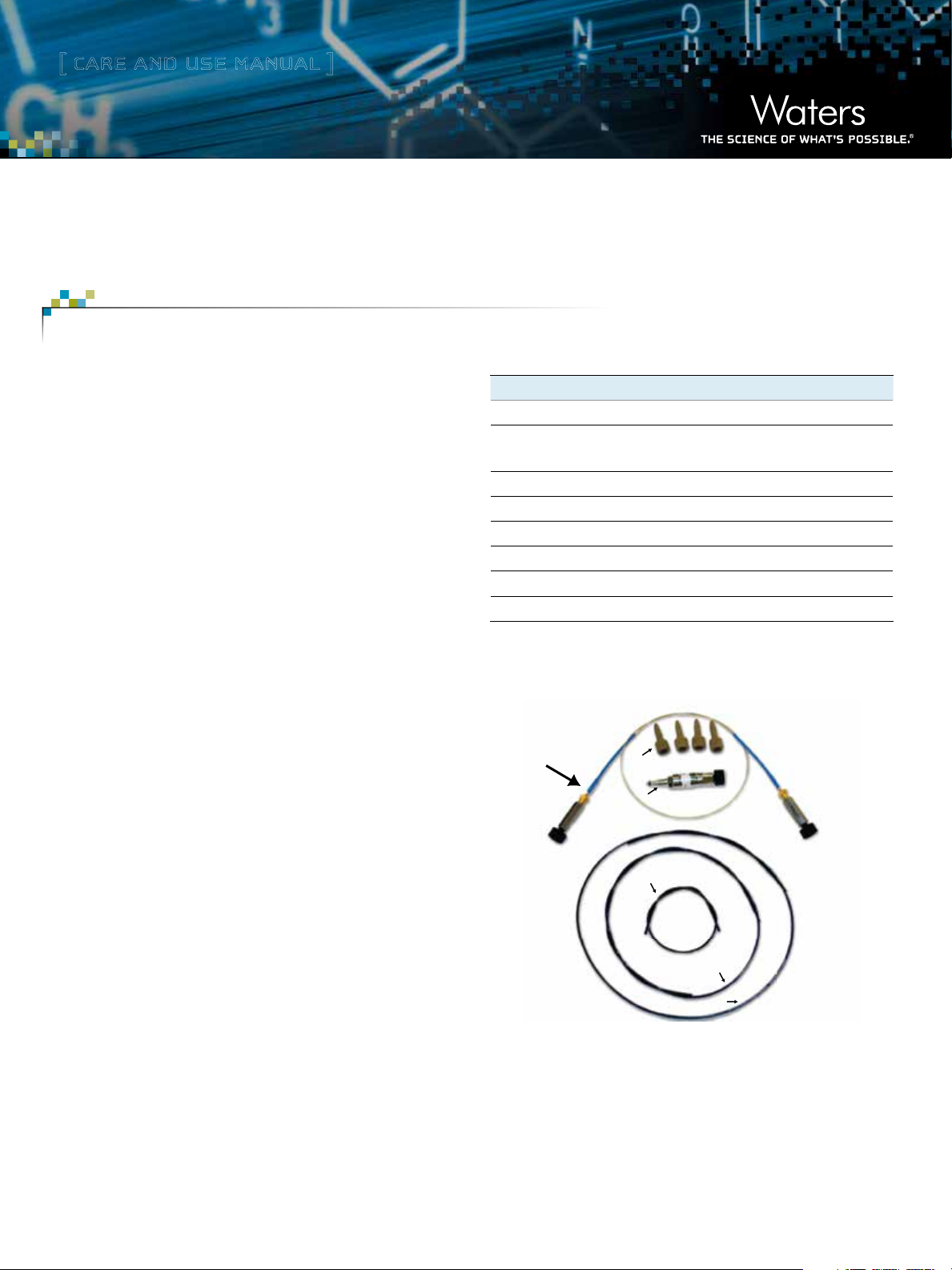
I. UPLC INTACT MASS ANALYSIS APPLICATION
KIT COMPONENTS
Description Qty Part Number
MassPREP Micro Desalting Column 1 186004032
Desalting Cartridge Manual Assembly,
Cap/Tube/Column
UPLC Intact Mass Analysis Solution 1 715001664
Intact Mass Tubing Kit. Kit contains: 1 205000548
Peek Compression Screw, Long, 10–32 4 410002276
Peek Tubing, 0.062 OD x .004 ID x 8.50 L 1 430001991
Peek Tubing, 0.062 OD x .004 ID x 15.04 L 1 430001992
Peek Tubing, 0.062 OD x .004 ID x 22.20 L 1 430001993
P/N: 430001988
P/N: 410002276
P/N: 186004032
1 430001988
VII. TIPS FOR SUCCESS
P/N: 430001991
P/N: 430001992
P/N: 430001993
Figure 1. UPLC® Intact Mass Analysis Application Kit Components.
Page 2
[ CARE AND USE MANUAL ]
II. INSTALLING THE PRE-COLUMN TUBING INTO
MASSPREP MICRO DESALTING COLUMN
Required materials:
1/4-inch open-end wrench
5/16-inch open-end wrench
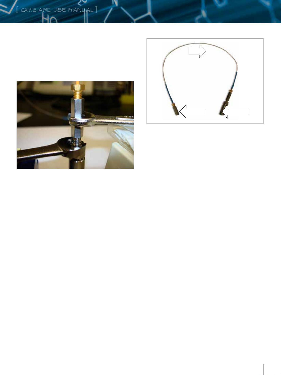
Flow
Solvent Inlet Solvent Outlet
Figure 3. Column assembly after attaching the column to the pre-column tubing.
III. CONNECTING THE COLUMN TO LCT
PREMIER MS
Figure 2. Installation of the pre-column tubing into the MassPREP Micro
Desalting Column.
Installation Procedure
1. Place the column on a flat surface (O-ring end facing up).
2. Remove the O-ring from the column.
3. Secure the column (P/N 186004032) with a 5/16-inch wrench
(bottom) as shown in Figure 2.
4. Tighten one end of the pre-column tubing (P/N 430001988)
into the column with a 1/4-inch wrench (a full turn beyond
hand-tight).
5. Connect the marked end (marked as solvent inlet) of the
column tubing assembly to the solvent outlet of the ACQUITY
UPLC® Column Heater (Figure 3).
Note: Proceed from this point to either section III, IV, or V
depending upon the type of mass spectrometer you have.
Installation Procedure
1. Connect one end of the 15.04-inch long PEEK tube (P/N
430001992) to the outlet of the column using a fitting (P/N
410002276).
2. Connect the other end of the tubing to the salt divert valve
(Port 2) using another fitting, as shown in the Figure 4. The
salt divert valve is located at the top-left corner of the LCT
Premier™ front panel.
3. Place the column in the column heater as shown in the Figure 6.
4. Connect one end of the 8.5-inch long PEEK tube (P/N
430001991) to Port 1 of the divert valve using a fitting
5. Connect the other end to the inlet of LCT Premier sample probe
using another fitting (Figure 4).
6. Use a larger diameter PEEK tube (0.062 o.d. x 0.005 or
0.01-inch i.d.) for the waste line (not included in the kit).
UPLC Intact MASS Analysis Application Kit
2
Page 3
[ CARE AND USE MANUAL ]
Column Heater
UPLC
Gradient
Waste
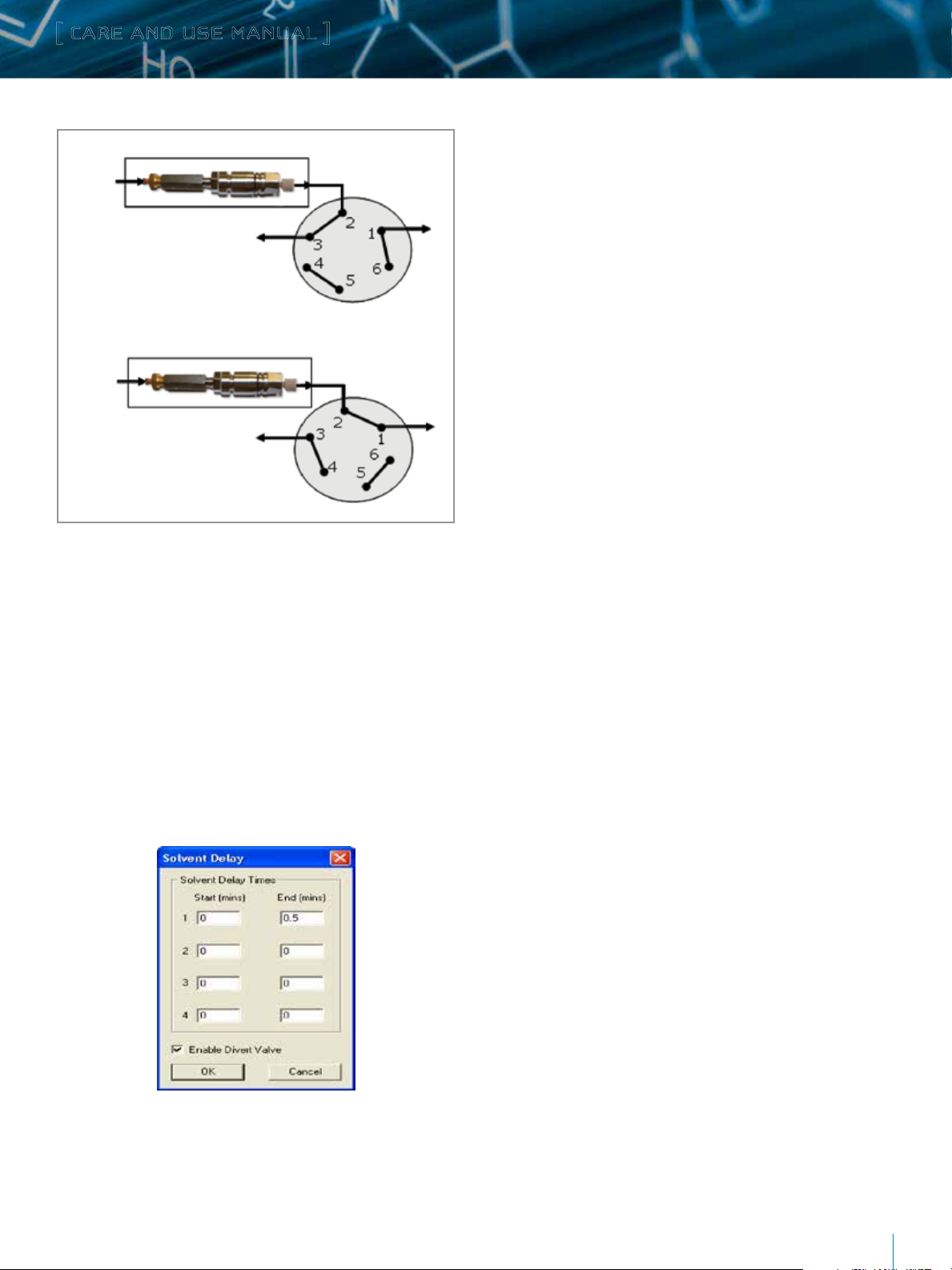
Position 1: Sample loading and salt divert to waste
UPLC
Gradient
Waste
Position 2: Sample elution to MS
Figure 4. Fluidic configuration for LC-MS (UPLC-LCT Premier) analysis. A postcolumn salt diversion valve (top-left corner of the LCT Premier) can be utilized
to divert buffers and nonvolatile salts to waste in the beginning of the LC/MS
analysis.
15.04”
8.5”
15.04”
8.5”
IV. CONNECTING THE COLUMN TO Q-TOF Premier
MS, AND SYNAPT HDMS
Neither Q-Tof Premier™ MS nor SYNAPT® HDMS® has an integrated
divert valve. However, an optional external 2 position valve (P/N
MS
MS
417000118) can be used with Q-Tof Premier and Synapt HDMS
mass spectrometers to divert buffers and nonvolatile salts present
in the sample to waste at the beginning of the LC/MS analysis.
Follow Steps 1–5 in Section II to attach the column to the pre
column tubing. Then follow Steps 12-17 below to connect the
column to the mass spectrometer.
1. Connect one end of the 15.04-inch long PEEK tube
(P/N 430001992) to the outlet of the column using a fitting
(P/N 410002276).
2. Connect the other end of the tubing to the external salt divert
valve (Port 4) using another fitting, as shown in the Figure 5.
3. Connect one end of the 8.5-inch long PEEK tube (P/N
430001991) to the external divert valve (Port 5).
4. Connect the other end to the inlet of MS sample probe (Figure 5).
The divert valve can be programmed from the MS Method Editor in
MassLynx®. To set a salt divert time, open MS Method Editor. Then
select Option> Solvent Delay on the MS Method Editor to open
the Solvent Delay dialog box. To enable the divert/injection valve
to be used as divert valve, select Enable Divert Valve. This diverts
the flow of solvent during a solvent delay period (0.5 min or user
defined value) either to, or away from, the source for the time
period shown in the solvent delay timetable (Table 1).
5. Place the column in the column heater as shown in the Figure 6.
6. Use a larger diameter PEEK tube (0.062 o.d. x 0.005 or
0.01-inch i.d.) for the waste line (not included in the kit).
Table 1. Salt divert timetable.
UPLC Intact MASS Analysis Application Kit
3
Page 4

[ CARE AND USE MANUAL ]
Column Heater
UPLC
Gradient
Position 1: Sample loading and salt divert to waste
UPLC
Gradient
15.04”
Waste
MS
8.5”
Position 2: Sample elution to MS
Figure 5. Fluidic configuration for LC-MS analysis using mass spectrometers with no integrated salt divert valve.
Figure 6. Column placement in the column heater.
15.04”
8.5”
MS
Communications Connections for the External Divert Valve
The optional external divert valve (417000118) can be controlled via line control using the connecting
wires with contact closures. Detailed instructions can be found in the valve operating manual.
1. Connect the red wire to pin #4 and black wire to GND to the terminal block (wires and terminal block
are included in the valve kit), as shown in the table below.
Pin # 1 2 3 4 5 6 GND
Wire - - - Red - - Black
UPLC Intact MASS Analysis Application Kit
4
Page 5

[ CARE AND USE MANUAL ]
2. Plug the terminal block into terminal block I/O (terminal block
I/O is located on the back panel of the external divert valve).
3. Connect the other side of the red wire to pin #6 and black to the
pin #7 of a different terminal block as shown in table below.
1 (+)
2 (-)
3 (+)
4 (-)
5 Ground
6 (Red)
7 (Black)
8
9
10 Ground Out
11 (+)
12 (-)
Gradient Start In
Stop Flow In
Switch 2 Out
Switch 3 Out
0-2 V Analog 2 Out
4. Plug the terminal block into Switch II (Switch II is located on the
back panel of the ACQUIT Y UPLC Binary Solvent Manager [BSM]).
V. CONNECTING THE COLUMN TO WATERS SQ
DETECTOR (SQD)
Follow steps 1-5 in Section II to attach the column to the pre
column tubing. Then follow Steps 18-23 below to connect the
column to the SQD.
1. Connect one end of the 22.20-inch long PEEK tube
(P/N 430001993) to the outlet of the column using a fitting
(P/N 410002276).
2. Connect the other end to the divert valve (Port 1) using another
fitting, as shown in the Figure 7. The divert valve is located at
the top-right corner of the SQD front panel.
3. Place the column in the column heater as shown in the Figure 6.
4. Connect one end of the 8.5-inch long PEEK tube (P/N
430001991) to Port 2 of the divert valve.
5. Connect the other end to the inlet of SQD sample probe (Figure 7).
6. Use a larger diameter PEEK tube (0.062 o.d. x 0.005 or
0.01-inch i.d.) for the waste line (not included in the kit).
The divert valve can be programmed from the ACQUIT Y UPLC
inlet Method Editor in MassLynx. To set a salt divert time, open
inlet Method Editor. Then select Inlet> Events on the ACQUITY
UPLC BSM Instrument Method to open the Events dialog box. To
enable the external divert valve to be used as a divert valve, select
Run Events and enter the events in the events table by clicking
line 1 and 2. Table 2 depicts a salt divert event. When Switch 2 is
in ON position at 0.01 min, the solvent flow is diverted to waste
until 0.51 min, and then the valve is switched to allow the solvent
flow to enter the MS.
Table 2. ACQUITY UPLC BSM console of salt divert timetable/events.
Table 3. Salt divert timetable for SQD.
The divert valve can be programmed from the
MassLynx. To set a salt divert time, open
Option> Method events
select
Method events dialog box. To enable the valve to be used as divert
Enable
valve, select
time period shown in the
defined value) then
. This diverts the flow of solvent to waste for the
the valve is switched allowing the flow to go to
on the
Method events
MS Method editor
MS Method Editor
MS Method Editor
timetable (0.5 min or user
. Then
to open the
the MS (Table 3).
in
UPLC Intact MASS Analysis Application Kit
5
Page 6

[ CARE AND USE MANUAL ]
MS
Column Heater
UPLC
Gradient
Position 1: Sample loading and salt divert to Waste
UPLC
Gradient
Position 2: Sample elution to MS
Figure 7. Fluidic configuration for LC-MS (UPLC-SQD) analysis. A post-column diversion valve located at the top right corner of the SQD
(typically used to direct calibrant for use in automatic tuning), was utilized to divert buffers and non-volatile salts to waste at the beginning
of the LC-MS analysis.
8.5”
22.20”
Waste
MS
8.5”
Waste
SQD Divert Valve
VI. SUGGESTED METHOD FOR MASS ANALYSIS
USING UPLC INTACT MASS ANALYSIS
APPLICATION KIT
Mass Spectrometry has become a powerful tool for therapeutic
proteins analysis. However, most therapeutic proteins are
stored in a matrix of biological buffers and non-volatile salts
and stabilizers. Thus, one of the most significant challenges
encountered during mass analysis of these proteins is processing
of the sample to remove these agents, which often form non-
covalent adducts that reduce MS response and further complicate
the resulting mass spectral data. The following offers two rapid,
sensitive and efficient desalting LC-MS methods that can be
utilized as a starting point with the UPLC Intact Mass Analysis
Application Kit for the characterization of an intact antibody and
its variants, and, constituent heavy and light chain structures.
a. Intact Antibody Analysis
A fast (4-min cycle time) and efficient LC-ESI-MS method was
used to profile multiple structural variants of an IgG. To minimize
cycle time, and maximize system performance, higher flow
rates (0.5 ml/min) were used for loading, desalting, and column
regeneration. A system controlled post-column valve was used
for waste diversion of sample buffers and salts. Additional
sawtooth (rapid) gradient cycles were applied to regenerate the
column to pre-injection conditions as part of each analysis (Table
4). Overlaid TICs (y-axis linked) for this experiment and the
associated summed mass spectra are shown in Figures 8 and 9,
respectively.
Tim e (min) %B Flow (ml /min) Curve
0.00 5 0.5 Initial
0.50 5 0.5 6
Load/WashDivert Flow
0.51 5 0.2 6
2.00 90 0.2 6
Gradient
2.10 5 0.5 6
2.70 90 0.5 6
2.80 5 0.5 6
3.40 90 0.5 6
Column
Washing and
Regeneration
3.50 5 0.5 6
4.00 5 0.5 6
A= 0.1 % Formic acid (Water)
B= 0.1 % Formic acid (ACN) Column temperature: 80 °C
Table 4. Gradient profile used for intact IgG1 analysis.
UPLC Intact MASS Analysis Application Kit
6
Page 7

[ CARE AND USE MANUAL ]
Pre-run Blank
0.5 µg IgG1
Post-run Blank
Figure 8. Total ion chromatograms (TICs) from Waters ACQUITY UPLC-LCT
Premier ESI-TOF MS analyses of an intact IgG1, and pre and post blank runs.
Column temperature was set to 80 °C for these analyses.
Pre-run Blank
0.5 µg IgG1
Max: 2 Counts
754 Counts
Tim e (min) %B Flow (ml /min) Curve
0.00 5 0.2 Initial
0.50 5 0.2 6
Load/WashDivert Flow
0.51 10 0.2 6
7.61 50 0.2 6
Gradient
8.0 90 0.5 6
8.1 5 0.5 6
TIME
8.6 90 0.5 6
8.7 5 0.5 6
9.2 90 0.5 6
Column
Washing and
Regeneration
9.3 5 0.5 6
9.8 5 0.5 6
A= 0.1 % Formic acid (Water)
B= 0.1 % Formic acid (ACN) Column temp.: 80 °C
Table 5. Gradient profile used for reduced IgG1 analysis.
Post-run Blank
Figure 9. Combined ESI-Tof (ACQUITY UPLC-LCT Premier ESI-Tof MS) mass
spectra of an intact IgG1 demonstrating regeneration to pre-injection
conditions.
2 Counts
m/z
b. Reduced Antibody Analysis
A ten minutes LC-ESI-MS method was used to resolve and
characterize IgG heavy and light chain subunits. For efficient
sample desalting, a system controlled post-column valve was used
for waste diversion of sample buffers and salts, prior to initiating
the analysis gradient. Additional sawtooth gradient cycles were
applied following the analysis gradient to regenerate the column
back to pre-injection conditions (Table 5). To minimize run cycle
time, and maximize system performance, higher flow rates
(0.5 ml/min) were applied for column regeneration. T he 10 min
LC-MS run largely resolved the earlier eluting light chain from the
later eluting glycosylated heavy chains (Figure 10).
Blank
MASs Spectrum
Heavy Chain
TIME
MASS Spectrum
Light Chain
Total Ion
Chromatogram
(1:3 µg load)
Figure 10. Total ion chromatograms (TICs) from LC-MS analyses of a reduced
IgG1, and pre and post blank runs. Combined ESI-TOF mass spectra of light and
heavy chains are shown in inset. Column temperature was set to 80 °C for
these analyses.
Pre and Post-run
UPLC Intact MASS Analysis Application Kit
7
Page 8

[ CARE AND USE MANUAL ]
MS Conditions
The MS parameters listed below can vary depending upon the
physical characteristics of the analyzed proteins, flow rate, and
MS probe position.
MS
Conditions
Ionization
Mode
Capillary
Voltage
Cone
Voltage
Desolvation
Temp
Source
Temp
Desolvation
Gas
Acquisition
range (m/z)
LCT Premier
MS
SYNAPT
HDMS
SQD*
ESI Positive ESI Positive ESI Positive
3–3.2 kV 2–3 kV 4.2–4.5 kV
40–50 V 35–37 V 39–45 V
350–450 °C 350–450 °C 350–450 °C
120–150 ° C 120 –150 ° C 120 –150 ° C
800 L/Hr 800 L/Hr 600–800 L/Hr
600–5000
(Intact)/
600–3000
(Reduced)
600–5000
(Intact)/
600–3500
(Reduced)
600–2000
(Reduced)
80–100 V
Ion Guide I
(Intact)/5 V
(Reduced)
Note: Desolvation temp, source temp, and desolvation gas values used in the
above table are based on 0.5 ml/min flow rate.
* Waters SQD parameters can be optimized using IntelliSmart™ software.
Tips for Success
Results obtained with the UPLC Intact Mass Analysis Application
Kit can vary depending upon the physical characteristics of the
analyzed proteins as well as the performance characteristics of
the LC-MS system, injector, and injection wash protocol used.
Additional sawtooth gradient cycles can be applied following
the analysis gradient to regenerate the column back to pre-
injection conditions. Suggested needle wash solvents and column
temperature for antibody LC-MS analysis are listed below:
Needle Weak Wash Solution Composition: 0.1% formic acid
in water
Needle Strong Wash Solution Composition:
65% acetonitrile/5% IPA/30% water in 0.1% formic acid
Column temperature: 80 °C
Separation of light and heavy chains of an antibody can be
obtained by optimizing gradient slope (gradient slope is measured
as percent of organic such as acetonitrile per mobile phase
volume passed through the column), flow rate, initial gradient
strength and column temperature. Set the column temperature to
80 °C. Use the gradient method in Table 5 as a starting point for
optimizing the separation of light and heavy chains of an antibody.
Follow the steps below to further optimize the separation of light
and heavy chains.
1. Find a gradient slope that provides an acceptable resolution
of your reduced antibody.
2. Use the result from the initial separation to design a gradient
(focus gradient slope) that improves the resolution between light
and heavy chains by focusing the gradient (narrow gradient).
3. Then adjust the gradient initial strength (while keeping the
gradient slope constant) to reduce the analysis time without
sacrificing the resolution.
Waters, The Science of W hat’s Possible, UPLC, ACQUIT Y UPLC, HDMS, SYNAPT, and MassLynx are registered trademarks of Waters
Corporation. MassPREP, LCT Premier, Q-Tof Premier, and IntelliStart are trademarks of Waters Corporation. All other trademarks are
property of their respective owners.
©2014 Waters Corporation. Produced in the U.S.A. June 2014 Rev B 715001664EN K P-PDF
Waters Corporation
34 Maple Street
Milford, MA 01757 U.S.A.
T: 1 508 478 2000
F: 1 508 872 1990
www.waters.com
 Loading...