

Page 1

Waters TQ Detector
Quick Start Guide
71500126803/Revision A
Copyright © Waters Corporation 2007.
All rights reserved.
Page 2

Copyright notice
© 2007 WATERS CORPORATION. PRINTED IN THE UNITED STATES OF
AMERICA AND IRELAND. ALL RIGHTS RESERVED. THIS DOCUMENT
OR PARTS THEREOF MAY NOT BE REPRODUCED IN ANY FORM
WITHOUT THE WRITTEN PERMISSION OF THE PUBLISHER.
The information in this document is subject to change without notice and
should not be construed as a commitment by Waters Corporation. Waters
Corporation assumes no responsibility for any errors that may appear in this
document. This document is believed to be complete and accurate at the time
of publication. In no event shall Waters Corporation be liable for incidental or
consequential damages in connection with, or arising from, its use.
Waters Corporation
34 Maple Street
Milford, MA 01757
USA
Trademarks
Connections Insight, ESCi, and Waters are registered trademarks of Waters
Corporation. ACQUITY UPLC, IntelliStart, IonSABRE, MassLynx, T-Wave,
UPLC, and ZSpray are trademarks of Waters Corporation.
Other trademarks or registered trademarks are the sole property of their
respective owners.
Page 3

Customer comments
Waters’ Technical Communications departme nt invites you to tell us of any
errors you encounter in this document or to suggest ide as for otherwise
improving it. Please help us better understand what you expect from our
documentation so that we can continuously improve its accuracy and
usability.
We seriously consider every customer comment we receive. You can reach us
at tech_comm@waters.com.
Waters Corporation
34 Maple Street
Milford, MA 01757
USA
iii
Page 4

Safety considerations
Some reagents and samples used with Waters® instruments ca n po se
chemical, biological, and radiological hazard s. Be sure you are aware of the
potentially hazardous effects of all substances you work with. Always observe
Good Laboratory Practice (GLP) guidelines, published by the U.S. Food and
Drug Administration, and consult your organization’s safety representative
for guidance.
When you develop methods, follow the “Pro tocol for the Ado ption of Analyt ical
Methods in the Clinical Chemistry Laboratory,” Ame rican Journal of Medical
Technology, 44, 1, pages 30–37 (1978). This protocol addresses good operating
procedures and the techniques necessary to validate system and method
performance.
Instrument-specific safety consideratio ns
Solvent leakage hazard
The source exhaust system is designed to be robust and leak-tight. Waters
recommends you perform a hazard analysis, assuming a maximum leak into
the laboratory atmosphere of 10% HPLC eluate.
Warning:
• To confirm the integrity of the source exhaust system, the
source seals must be renewed at intervals not exceeding one
year.
• The source seals can withs tand exposure only to specific
solvents, see Appendix C in the Wat ers TQ Det ector Oper ator’ s
Guide. If you intend to use solvents other than those listed,
you must first determine whether those solvents are
compatible with the composition of the seals.
iv
Page 5
Flammable solvents hazard
Warning: Where signif icant quantities of flammable solvents are
involved, the source must receive a continuous flow of nitrogen to
prevent possible ignition within that enclos ed space.
Never let the nitrogen supply pressure fall below 400 kPa (4 bar, 58 psi)
during analyses that require flammable solvents. Connect to the LC output
with a gas-f a il co n n e ctor to stop the LC solvent if th e ni t rogen suppl y fa i l s.
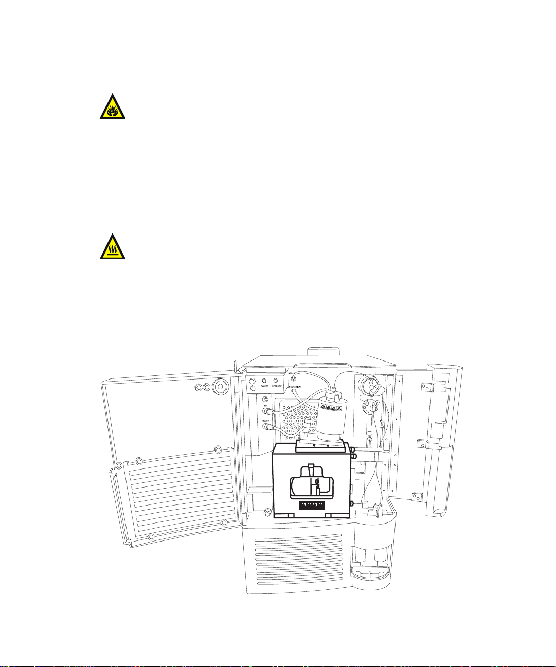
High temperature hazard
Warning: The source enclosure can be hot. To avoid burn injuries,
avoid touching the source enclosure when operating or servicing the
TQ Detector.
Waters TQ Detector high temperature hazard:
Source enclosure ass em bly
v
Page 6

High voltage hazard
Warning:
• To avoid electric shock, do not remove the TQ Detector’s protective
panels. The components they cover are not user-serviceable.
• To avoid non-lethal electric shock, any equipment connected to the
ESI and IonSABRE™ APCI probes must be grounded.
• When the TQ Detector is in Operate mode, certain ext ernal surfaces
can conduct high voltages. To avoid non-lethal electric shock, make
sure the instrument is in Standby mode before touching areas
marked with this high voltage warning symbol.
Safety advisories
Consult Appendix A for a comprehensive list of warning and caution
advisories.
vi
Page 7

Operating this device
When operating this device, follow standard quality cont rol procedures and
the guidelines presented in this section.
Symbols
Symbol Definition
Intended use
The Waters Tandem Quadrupole (TQ) Detector is intended to be used as a
research tool to deliver authentica ted mass measurement in both MS and
MS/MS modes.
The Waters TQ Detector can be used for general In Vitro Diagnostic
applications, only by professionally trained and qualified laboratory
personnel.
E C RE P
Authorized Representative of the
European Community
The CE symbol serves as
confirmation of the conformity of a
product with all European
Community directives applicable to
that product.
For in vitro diagnostic use.
IV D
The Waters TQ Detector is CE-marked according to the
European Union In Vitro Diagnostic Device Directive 98/79/EC.
vii
Page 8

Calibration
To calibrate LC systems, follow acceptable calibration method s using at least
five standards to generate a standard curve . The concentration range for
standards should cover the entire range of quali ty-control samples, typical
specimens, and atypical specimens.
To calibrate mass spectrometers, consult the calibration section of the
operator’s guide of the instrument you are calibrating.
Quality control
Routinely run three quality-control samples that represent subnormal,
normal, and above-normal levels of a compound. Ensure that quality-control
sample results fall within an acceptable range, and evaluate precision from
day to day and run to run. Data col lected when qualit y control samples are ou t
of range might not be valid. Do not r eport the se dat a until you ar e cert ain that
the instrument performs satisfactorily.
When analyzing samples from a co m plex matrix such as soil, tissue,
serum/plasma, whole blood, etc., note tha t the mat rix components can
adversely affect LC/MS results, enhancing or suppres sing ionization. To
minimize these matrix effects, Wate rs recommends you adopt the following
measures:
viii
• Prior to the instrumental analysis, use appropria te sample
pretreatment such as protein precipitation, liquid/liquid extraction
(LLE), or solid phase extraction (SPE) to remove matrix interferences.
• Whenever possible, verify method accuracy and precision using
matrix-matched calibrators and QC samples.
• Use one or more internal standard compounds, preferably
isotopically-labeled analytes.
Page 9

IVD authorized representative information
IVD authorized representative
Waters Corporation (Micromass UK Limited) is
registered in the United Kingdom with the
Medicines and Healthcare P roducts Regulatory
Agency (MHRA) at market Towers, 1 Nine Elms
Lane, London, SW8 5NQ. The referenc e number
is IVD000167.
Waters Corp o ra tion (Microm a ss UK Ltd.)
Floats Road
Wythenshawe
Manchester M23 9LZ
United Kingdom
Telephone: +44-161-946-2400
Fax: +44-161-946-2480
Contact: Quality manager
ix
Page 10

x
Page 11

Table of Contents
Safety considerations .......................................................................................... iv
Instrument-s pe c if i c sa f et y co n si d erations............. ... ............. .. .......................... iv
Flammable solvents hazard ................................................................................ v
High temperature hazard.................................................................................... v
High voltage haza r d......... .. .......................... ... ............. .. .. ............. ... ................... vi
Safety advisories................................................................................................. vi
Operating this device ......................................................................................... vii
Symbols ............................................................................................................. vii
Intended use...................................................................................................... vii
Calibration ....................................................................................................... viii
Quality control ................................................................................................. viii
IVD authorized representative information ................................................. ix
IVD authorized representative .......................................................................... ix
1 Waters TQ Detector Overview ............................................................ 1-1
Overview ............................................................................................................. 1-2
Waters TQ Dete c to r.......................... ... ............. .. ............. .. .............. .. ............. . 1-2
ACQUITY TQD UPLC/MS system .......... .. .. ................................................... 1-4
MassLynx mass spectrometry software and data system ............................. 1-5
ACQUITY UPLC Console......................................................................... ....... 1-6
Ionization techniques and source probes ................................................... 1-7
Electrospray i on i za tion (ESI)..... .. ............. .. .............. .. ............. .. .............. .. ..... 1-7
Combined electrospray ionization and atmospheric p ressure chemical ionization
(ESCi) ......................................................................................................... 1-7
Atmospheric pressure chemical ionization..................................................... 1-8
Atmospheric pressure photoionization ........................................................... 1-8
Table of Contents xi
Page 12

Ion optics ............................................................................................................. 1-9
MS operating modes ....................................................................................... 1-10
MS/MS operating modes ................................................................................ 1-11
Product (daug h t er) ion mode. .............. .. ............. .. ............. ... ............. .. .......... 1-11
Precursor (pare n t) ion mode...... ............. .. ............. ... ............. .. .. .............. .. ... 1-1 2
Multiple reaction monitoring mode .............................................................. 1-12
Constant neutral loss mode........................................................................... 1-13
Sample inlet ...................................................................................................... 1-14
Vacuum system ................................................................................................ 1-14
Rear panel .. ... ............. .. .. .. ... .. .. ............. ... .. .. .. .. .............. .. .. .. .. ... ............. .. .. ... .. .. . 1-15
IntelliStart fluidics system overview ......................................................... 1-16
IntelliStart fluidics system operation ........................................................ 1-17
Operating the IntelliStart fluidics system from the ACQUITY UPLC
Console . .. ............. .. .............. .. ............. .. .............. .. ............. .. .............. .. .. ... 1-1 7
Operating the IntelliStart fluidics system from the Tune window............. 1-18
Programming the MS method to operate the IntelliStart fluidics system. 1-18
2 Preparing the Waters TQ Detector for Operation ......................... 2-1
Starting the TQ Detector ................................................................................. 2-2
Configuring IntelliStart..................... ............................................... .. ............. 2-6
Verifying the instrument’s state of readiness................................................ 2-6
Tuning and calibration information ............................................................... 2-6
Running the TQ Detector at high flow rates.................................................. 2-7
Monitoring the TQ Detector LEDs.................................................................. 2-8
Preparing the IntelliStart fluidics system .................................................. 2-9
Installing the solvent manifold drip tray........................... .. .......................... 2-9
Installing the reservoir bottles..................... .......................................... ....... 2-10
Diverter valve positions................................................................................. 2-11
Purging the infusion syringe......................................................................... 2-13
Rebooting the TQ Detector ........................................................................... 2-14
Rebooting the TQ Detector by pressing the reset button ............................ 2-14
xii Table of Contents
Page 13

Shutting down the TQ Detector .................................................................. 2-15
Putting the TQ Detector in Standby mode for overnight shutdown........... 2-15
Complete TQ Detector shutdown.................................................................. 2-16
Emergency TQ Detector shutdown............................................................... 2-17
3 ESI and ESCi Modes of Operation ..................................................... 3-1
Introduction ....................................................................................................... 3-2
Installing the ESI probe .................................................................................. 3-2
Required materials .......................................................................................... 3-2
Installing the corona pin ................................................................................. 3-5
Required materials .......................................................................................... 3-5
Optimizing the ESI probe for ESCi operation ........................................... 3-7
Required materials .......................................................................................... 3-7
Removing the corona pin ................................................................................ 3-9
Required materials .......................................................................................... 3-9
Removing the ESI probe ............................................................................... 3-11
Required materials ........................................................................................ 3-11
4 Operating the Waters TQ Detector .................................................... 4-1
Setting-up the instrument .............................................................................. 4-2
Required materials .......................................................................................... 4-2
Performing a sample tune .............................................................................. 4-7
Required materials .......................................................................................... 4-7
Developing experiment methods .................................................................. 4-9
Required materials .......................................................................................... 4-9
Verifying the sys t em us in g Sys t em QC ........... ............. .. ... .. .. .. .. .............. .. . 4-11
A Safety Advisories ..................... ..... ..... ................................................... A-1
Warning symbols ............................................................................................... A-2
Task-specific hazard warnings........................................................................ A-2
Warnings that apply to particular instruments, instrument components, and
sample types............................................................................................... A-3
Table of Contents xiii
Page 14

Caution symbol .................................................................................................. A-5
Warnings that apply to all Waters instruments ......................................... A-5
Electrical and handling symbo l s ............. .. ... .. .. .. ............. ... .. .. .. .. ... ............. . A-13
Electrical symbols.......................................................................................... A-13
Handling symbols .......................................................................................... A-14
xiv Table of Contents
Page 15

1 Waters TQ Detector Overview
This chapter describes the instrument, including its controls and gas
and plumbing connections.
Contents:
Topic Page
Overview 1-2
Ionization techniques and source probes 1-7
Ion optics 1-9
MS operating modes 1-10
MS/MS operating modes 1-11
Sample inlet 1-14
Vacuum system 1-14
Rear panel 1-15
IntelliStart fluidics system overview 1-16
IntelliStart fluidics system operation 1-17
1-1
Page 16
Overview
Waters TQ Detector
The Waters® TQ Detector is a tandem quadrupole, atmospheric pressure
ionization (API) mass spectrometer. Designed for routine UPLC™/MS/MS
analyses in quantitative and qualitative applications, it can operate at fast
acquisition speeds compatible with ultra performance LC.
Waters provides these ion sources with the instrument as standard
equipment:
• ZSpray™ (dual orthogonal sampling) interface.
• Multi-mode ESCi
chemical ionization (APCI) and electrospray ionization (ESI).
Optional ionization modes are IonSABRE™ APCI and APPI (atmospheric
pressure photoionization) .
For TQ Detector specifications, see the Waters TQ Detector Site Preparation
Guide.
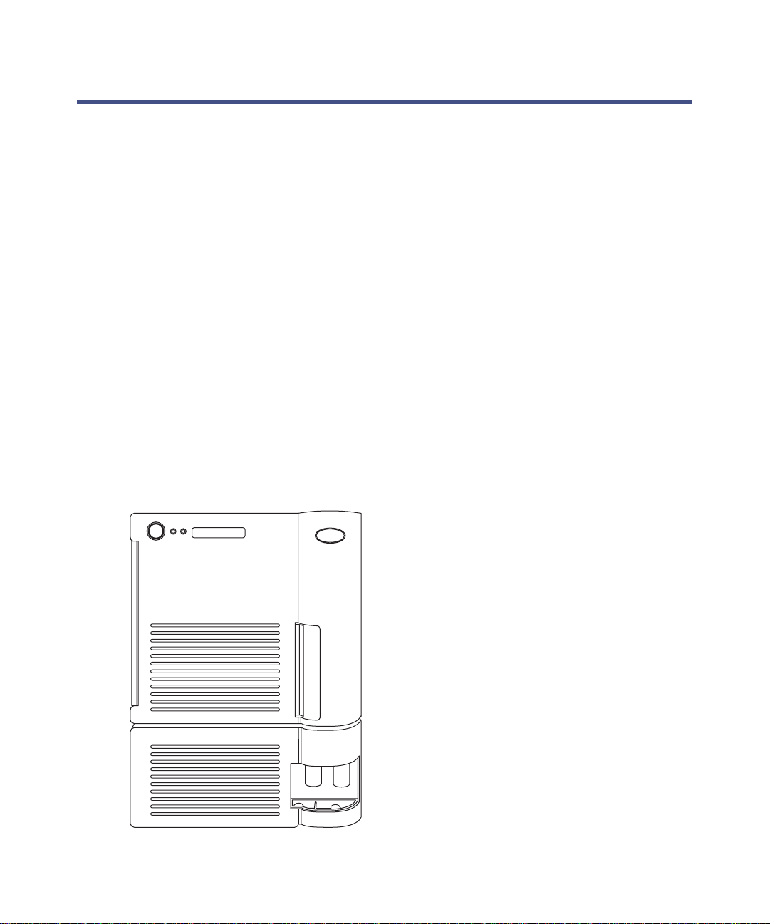
Waters TQ Detector:
®
ionization switching for atmospheric pressure
1-2 Waters TQ Detector Overview
TP02592
Page 17
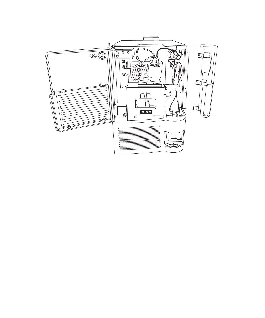
Waters TQ Detector with doors open:
HV
PROBE
NEBULIZER
POWER OPERATE
DESOLVATION
V
H
E
B
O
R
P
IntelliStart technology
TP02627
IntelliStart™ technology monitors LC/MS/MS performance and reports when
the TQ Detect or is ready for use.
The IntelliStart software automatically tune s and mass calibrates the TQ
Detector and displays performance readbacks . In tegrated with MassLynx™
mass spectrometry software and ACQUITY UPLC™ Console software,
IntelliStart enables simplified set-up of the system for use in routine
analytical and open access applications.
The IntelliStart fluidics system is built into the TQ Detector. It delivers
sample directly to the MS probe from the LC column or from two integral
reservoirs. The integral reservoirs can also deliver sample through direct or
combined infusion so that you can optimize instrument performance at
analytical flow rates.
See also: The TQ Detector online Help for further details of IntelliStart.
Overview 1-3
Page 18

ACQUITY TQD UPLC/MS system
Note: The Waters TQ Detector is designed for compatib ility with the
ACQUITY UPLC system; if you are not using an ACQUITY UPLC system,
refer to the documentation relevant to the LC syst em being used.
The ACQUITY TQD UPLC/MS system includes an ACQUITY UPLC system
and the Waters TQ Detector.
ACQUITY UPLC system
The ACQUITY UPLC system includes a binary solvent manager, sample
manager, column heater, optional sample organizer, op tional detectors, and a
specialized ACQUITY UPLC column. Waters MassLynx mass spectrometry
software controls the system.
See also:
• ACQUITY UPLC System Operator’s Guide
• Controlling Contamination in LC/MS System s (part number
715001307). You can find this document on http: //www.waters.com; click
Services and Support and then Support Center.
1-4 Waters TQ Detector Overview
Page 19
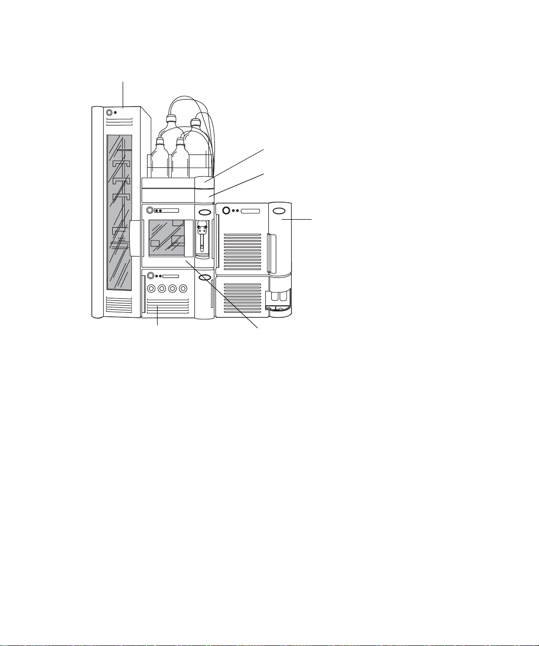
Waters ACQUITY TQD:
Sample organizer (option al)
manager
Solvent tray
Column heater
TP02597
Sample managerBinary solvent
TQ Detector
MassLynx mass spectrometry software and data system
MassLynx is a high-performance mass spect rometry application that acquires,
analyzes, manages, and distributes ultra-violet (UV), evaporative light
scattering, analog, and mass spectrometry data.
MassLynx software permits these major operations:
• Configuring the instrument.
• Creating LC inlet and MS/MS methods that define operating
parameters for a run.
• Using IntelliStart softwar e to tune and m a ss calibrate the TQ Detector.
• Running samples.
• Monitoring the run.
• Acquiring data.
• Processing data.
Overview 1-5
Page 20
•Reviewing data.
•Printing data.
See also: MassLynx 4.1 user documentation and online Help for more
information on installing and using MassLynx software.
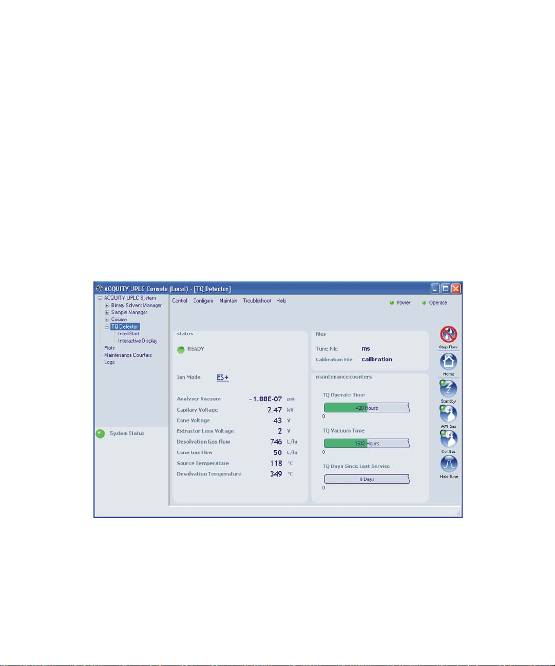
ACQUITY UPLC Console
The ACQUITY UPLC Console is a software application with which you
configure settings, monitor perfor manc e, run diagnostic tests, and maintain
the system and its modules. The ACQUITY UPLC Console functions
independently of MassLynx and does not recognize or control the data system.
See also: ACQUITY UPLC System console online Help for details of the TQ
Detector.
TQ Detector ACQUITY UPLC Console page:
1-6 Waters TQ Detector Overview
Page 21

Ionization techniques and source probes
Electrospray ionization (ESI)
In electrospray ionization (ESI), a strong electrical charge is given the eluent
as it emerges from a nebulizer. The droplets that compose the resultant
aerosol undergo a reduction in size (solvent evaporat ion). As solvent continues
to evaporate, the charge density incre ases until the dr oplet su rfac es eject io ns
(ion evaporation). The ions can be singly or multiply charged. The multiply
charged ions are of particular interest because the TQ Detector separates
them according to their mass-to-charge ratios (m/z), permitting the detection
of high-molecular-weight compounds.
The instrument can accommodate eluent flow rates of up to 1 mL/min.
Combined electrospray ionization and atmospheric pressure chemical ionization (ESCi)
Combined electrospray ionization and atmospheric pressure chemical
ionization (ESCi) is supplied as standard equipment on the TQ Detector. In
ESCi, the standard ESI probe is used in conjunction with a corona pi n to allow
alternating acquisition of ESI and APCI ionization data, facilitating high
throughput and wider compound coverage.
Ionization techniques and source probes 1-7
Page 22
ESCi mode:
Corona pin
TP02695
Sample cone tip
See also: “Electrospray ionization (ESI)” on page 1-7.
Atmospheric pressure chemical ionization
A dedicated high performance atmospheric pressure chemical ionization
(APCI) probe is offered as an option.
See also: The Waters TQ Detector Operator’s Guide for full details.
Atmospheric pressure photoionization
Atmospheric pressure photoionization (APPI) is offered as an option. It uses
photons generated by a krypton-dischar ge ultra-violet (UV) lamp ( ∼10.2 eV) to
produce sample ions from vaporized LC eluent.
1-8 Waters TQ Detector Overview
Page 23
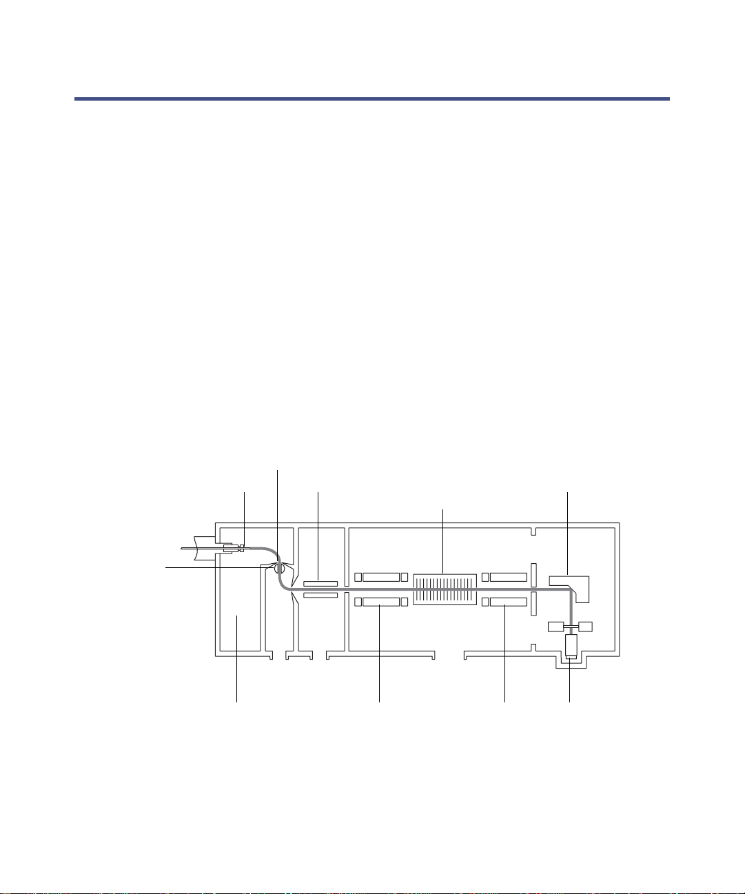
Ion optics
The TQ Detector’s ion optics operate as follows:
• Samples from the LC or Intellistart fluidics system are introduced at
atmospheric pressure into the ionization source.
• The ions pass through the sample cone into the vacuum system.
• The ions pass through the transfer optics to the fir st quadrupole where
they are filtered according to their mass-to-charge ratio (m/z).
• The mass-separated ions pass into the T-Wave™ collision cell where
they either undergo collision-induced dissociation (CID) or pass to the
second quadrupole. Any fragment ions are then mass-analyzed by the
second quadrupole.
• The transmitted ions are detected by the photomultiplier detection
system.
• The signal is amplified, digitized, and sent to the MassLynx mass
spectrometry software.
Ion optics overview:
Sample cone
Sample inlet Transfer optics
T-W ave co llision
cell
Conversion dynode
Isolation valve
Z-Spray ion sourc e Quadrupole 1
(MS1)
Quadrupole 2
(MS2)
Detector
Ion optics 1-9
Page 24

MS operating modes
The following table shows the MS operating modes.
MS operating modes :
Operating mode MS1 Collision cell MS2
MS1 Resolving
(scanning)
MS2 Pass all masses Resolving
SIR Resolving (static) Pass all masses
The MS1 mode, in which MS1 is used as the mass filter, is the most common
and most sensitive method of per formi ng MS analysis. It i s di rectly analogous
to using a single-quadrupole mass spectrometer.
The MS2 mode of operation is used, with collision gas p resent, when switching
rapidly between MS and MS/MS operat ion (for example, in survey scan mode).
It also provides a useful tool for instrument tuning and calibration before
MS/MS analysis and for fault diagnosis.
The selected ion recording (SIR) mode of operation is used as a quantitation
mode when no suitable fragment ion can be found to perform a more specific
multiple reaction monitoring (MRM) analysis.
Pass all masses
(scanning)
1-10 Waters TQ Detector Overview
Page 25
MS/MS operating modes
The following table shows the MS/MS operating modes.
MS/MS operating modes :
Operating mode MS1 Collision cell MS2
Product
(daughter) ion
Static (at
precursor mass)
spectrum
Precursor
Scanning Static (at product
(parent) ion
spectrum
MRM Static (at
precursor mass)
Constant neutral
loss spectrum
Scanning
(synchronized
with MS2)
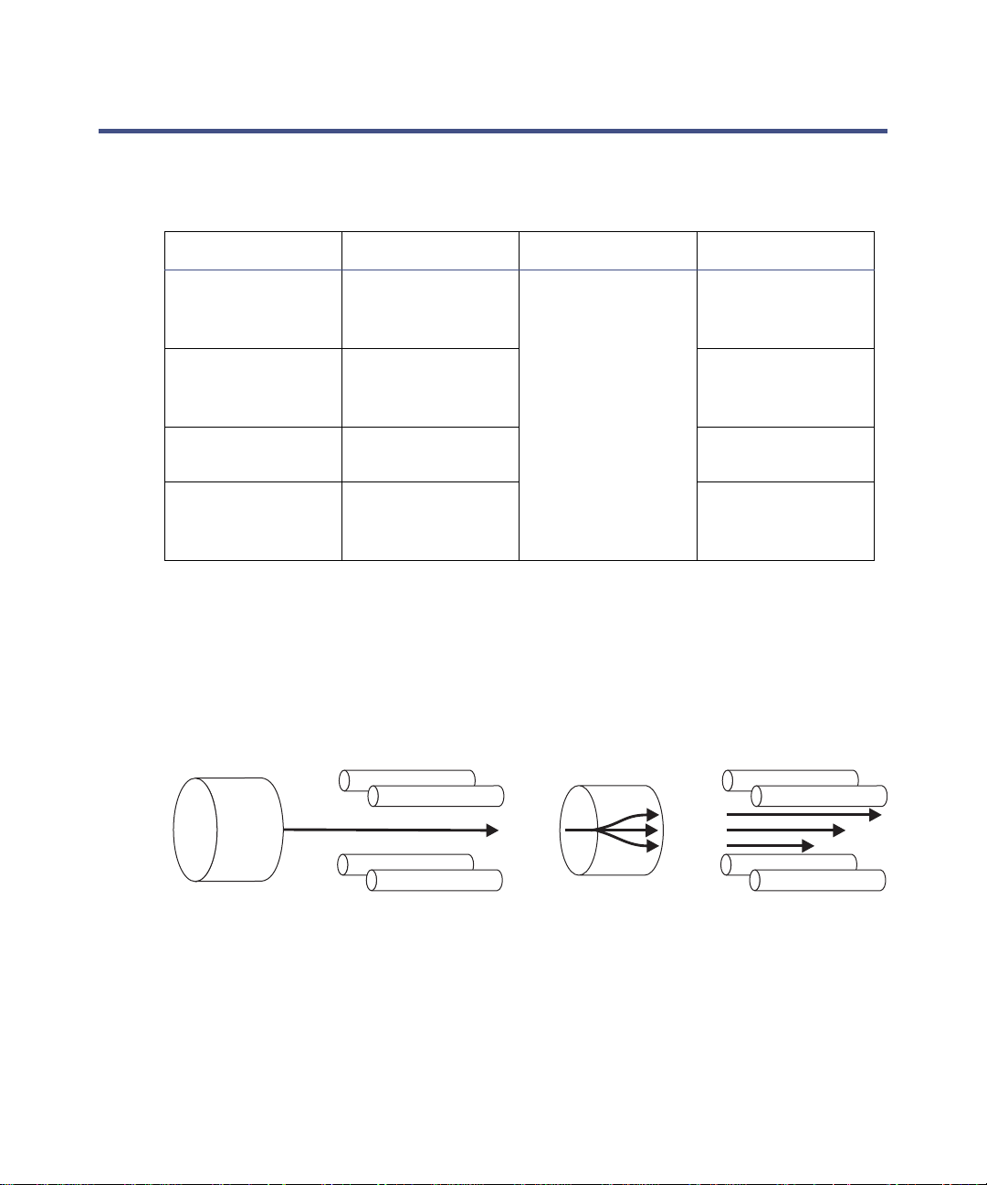
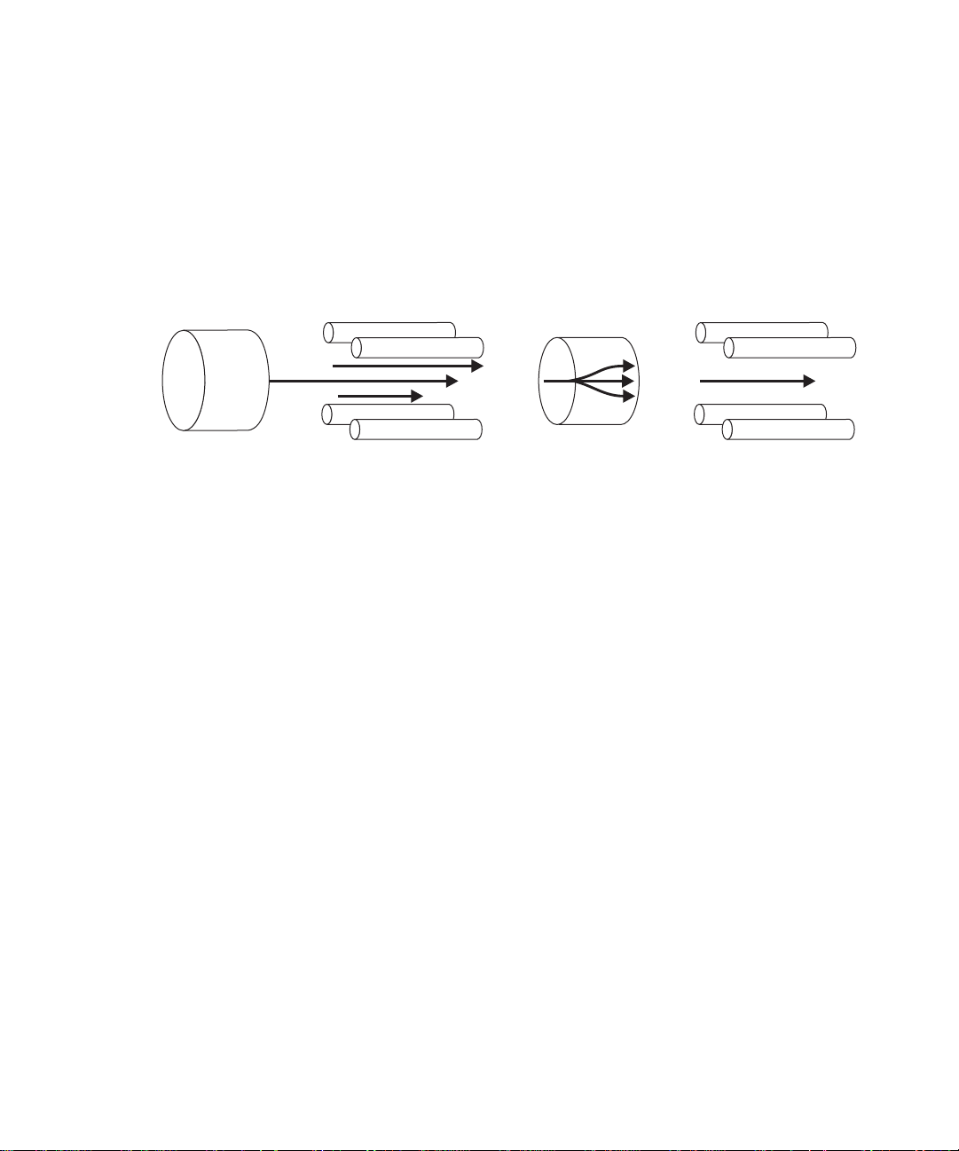
Product (daughter) ion mode
Product ion mode is the most commonly used MS/MS operating mode. An ion
of interest is selected for fragment ation in the collision cell, thus yielding
structural information.
Product ion mode:
Pass all masses Scanning
mass)
Static (at product
mass)
Scanning
(synchronized
with MS1)
MS1
Static (at precursor mass)
Collision cell
Pass all masses
Typical applications
• Structural elucidation (for example, peptide sequencing)
MS/MS operating modes 1-11
MS2
Scanning
Page 26
• Method development for MRM screening studies:
– Identifying product ions for use in MRM transitions.
– Optimizing CID tuning conditions to maximize the yield of a specific
product ion to be used in MRM analysis.
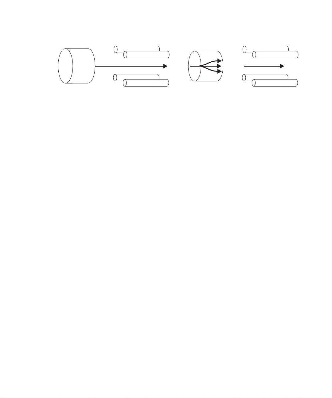
Precursor (par ent) ion mode
Precursor ion mode:
MS1
Scanning
Typical application
You typically use the precursor ion mode for structural elucidation–that is, to
complement or confirm product scan data–by scanning for all the precursors of
a common product ion.
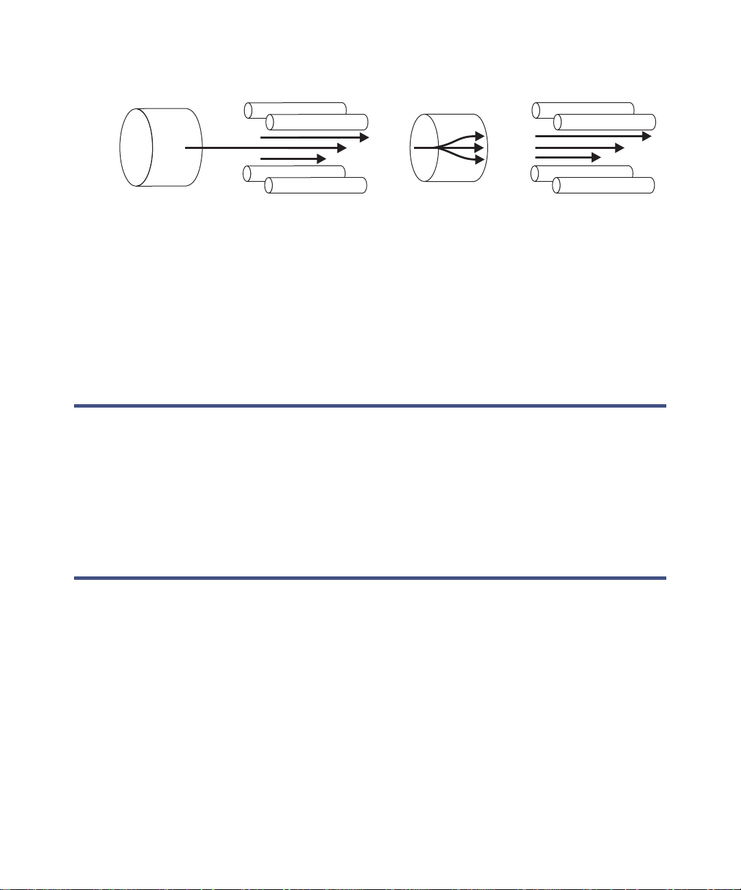
Multiple reaction monitoring mode
MRM mode is a highly selectiv e MS/MS equivalent of SIR. As both MS1 and
MS2 are static, greater dwell time on the ions of interest is allowed, and
therefore better sensitivity compared to scanning MS/MS. This is the most
commonly used acquisition mode for quantitative analysis, allowing the
compound of interest to be isolated from the chemical background noise.
Collision cell
Pass all masses
MS2
Static (at product mass)
1-12 Waters TQ Detector Overview
Page 27
Multiple reaction monitoring mode:
MS1
Static (at precursor mass)
Typical application
You typically use MRM to quantify known analytes in complex samples:
• Drug metabolite and pharmacokinetic studies.
• Environmental, for example, pest icide and herbicide analysis.
• Forensic or toxicology, for example, screening for target drugs in sport.
• MRM does not produce a spectrum because only one transition is
monitore d at a time. As in SI R , a c h romatogram is produce d.
Constant neutral loss mode
Constant neutral loss mode detects the loss of a specific neutral fragment or
functional group from an unspecified precur sor or precursors.
The scans of MS1 and MS2 are synchronized. When MS1 transmits a specific
precursor ion, MS2 “lo oks” to s ee whether that p recu rsor lo ses a fra gment of a
certain mass. If it does, the loss registers at the detector.
In constant neutral loss mode, the spectrum show s the masses of all
precursors that actually lost a fragment of a certain mass .
Collision cell
Pass all masses
MS2
Static (at product mass)
MS/MS operating modes 1-13
Page 28
Constant neutral lo ss mode:
Typical application
You typically use constant neutral loss mode to screen mixtures for a specific
class of compound that is character ized by a common f ragmentat ion pathway,
indicating the presence of compounds containing a common functional group.
Sample inlet
Either of two methods delivers solvent and sample to the installed probe:
• An LC system, which delivers the eluent from an LC analysis.
• IntelliStart fluidics system, which uses on-board solutions to automate
instrument optimization. You can de liver solutions by direct or
combined infusion.
Vacuum system
MS1
Scanning
(synchronized with MS2)
Collision cell
Pass all masses
MS2
Scanning
(synchronized with MS1)
An external roughing (rotary vane) pump and an internal split- flow
turbomolecular pump combine to create the source vacuum. The
turbomolecular pump evacuates the analyzer and ion transfer region.
Vacuum leaks and electrical or vacuum pump failures cause vacuum loss,
which protective interlocks guard against. The system monitors
turbomolecular pump speed and continuously measures vacuum pressure
with a built-in Pirani gauge. The gauge also serves as a switch, discontinuing
operation when it senses vacuum loss.
A vacuum isolation valve isolates the source from the mass analyzer, allowing
routine source maintenance without venting.
1-14 Waters TQ Detector Overview
Page 29

Rear panel
The following figure shows the rear panel locations of the connectors used to
operate the TQ Detector with external devices.
TQ Detector rear panel:
Power cord
Nitrogen inlet
Source vent
Turbo vacuum
Collision cell
gas inlet
V~ 200-240
Hz 50-60
VA 1200
APIGAS
6.9BAR MAXIMUM
SOURCEVENT
Waters Corporation
34 Maple Street Milford, MA01757 U.S.A.
VACUUM
COLLISION
GAS
1.0BAR
MAXIMUM
VACUUM
Serial Number
ACN 065444751
+
+
1
1
InjectStart
In
Analog
Out
2
2
-
-
Ground
3
3
Ground
+
+
4
4
In
Event
NotUsed
-
-
5
5
+
6
6
StopFlow
Switch3
Out
7
7
-
Ground
8
8
Ground
+
9
9
Out Out
Switch4
Switch4
10
10
-
IVD
RS232
ETHERNET
Event inputs
and outputs
Shielded
Ethernet
PUMP
Roughing pump
relay switch
Source vacuum
Rear panel 1-15
Page 30

IntelliStart fluidics system overview
The IntelliStart fluidics system is built into the TQ Detector. The system
delivers sample directly to the MS probe in one of two ways:
• From the LC column
• From two integral reservoirs.
Tip: The integral reservoirs can also deliver sample through direct or
combined infusion to enable optimization at analytical flow rates.
The IntelliStart system incorporates a multi-position valve with these
attributes:
• An input connection from an external LC column.
• An input connection from the TQ Detector’s infusion syringe. (The TQ
Detector’s infusion syringe is also connected to two reservoirs, A and B.
In the software, you specify which reservoir to draw from.)
• An output connection to the TQ Detector’s probe.
• An output connection to a waste line.
LC flow:
Probe
LC
Column
Syringe
LC Waste
1-16 Waters TQ Detector Overview
Idle
B
Off
A
Off
Reservoir A Reservoir B
Page 31

IntelliStart fluidics system operation
Control of solvent and sample delivery during auto-tuning, auto-calibration,
and method development is automatically performed by the sof tware.
IntelliStart configuration requirements can be set in the system console. You
can edit the parameters, frequency, and extent of the automation you want
IntelliStart to perform.
See also: The TQ Detector online Help for further details of IntelliStart.
Operating the IntelliS tart fluidics system f rom the ACQUITY UPLC Console
To operate the IntelliStart fluidi cs system from the Instrument Console:
1. In the MassLynx window, click MS Console.
2. In the ACQUITY UPLC Console system tree, expand TQ Detector.
3. Click Interactive Display.
4. In the ACQUITY UPLC Console window, click the current flow rate.
5. In the Select Flow Rate dialog box, enter a new flow rate.
IntelliStart fluidics system operation 1-17
Page 32

6. Click OK.
7. Click Reservoir A or B.
8. In the Select Reservoir dialog box, click A or B.
9. Click OK.
Tip: If the selected reservoir is different from the current reservoir, the
system purges as the reservoir changes.
10. Click the current diverter valve position label.
11. In the Select a Flow State dialog box, select the required flow state.
12. Click OK.
13. Click to start.
Tip: A status indicates the amount of fluid in the syringe and the
amount of time remaining before the fluid empties. When the syringe is
empty the system becomes idle.
14. Click to refill the syringe or to purge the system.
15. Click to stop the current action.
Operating the IntelliStart fluidics system from the Tune window
To operate the IntelliStart fluidics system from the Tune window:
1. In the MassLynx window, click MS Tune.
2. In the TQ Detector Tune window, click the Fluidics page.
3. Set the Flow Control parameters according to the instructions in the
MassLynx online Help.
Programming the MS method to operate the IntelliStart fluidics system
In the MS method, you can program the operation of the system’s
multi-position valve to infuse sample during a run. The valve can also divert
LC flow to waste as a timed event.
1-18 Waters TQ Detector Overview
Page 33

To program the MS method:
1. In the MassLynx window, click MS Method.
2. In the MS Methods window, click Options > Method Events.
3. In the Method events dialog box, select the appropriate flow state, as
shown in the following table.
Flow states :
State LC Syringe
LC TQ probe Waste
Combined TQ probe TQ probe
Infusion Waste TQ Probe
Waste Waste Waste
No change No change No change
Tip: At instrument power-up, the LC state is waste.
See also: MassLynx online Help topic “Advanced Methods and Events ”.
IntelliStart fluidics system operation 1-19
Page 34

1-20 Waters TQ Detector Overview
Page 35

2 Preparing the Waters TQ
Detector for Operation
This chapter describes how to start and shut-down the TQ Detector.
Contents:
Topic Page
Starting the TQ Detector 2-2
Preparing the IntelliStart fluidics system 2-9
Rebooting the TQ Detector 2-14
Shutting down the TQ D etector 2-15
2-1
Page 36

Starting the TQ Detector
Note: The Waters TQ Detector is designed for compatib ility with the
ACQUITY UPLC system; if you are not using an ACQUITY UPLC system,
refer to the documentation relevant to the system being used.
Caution: Using incompatible solvents can cause severe damage to the
instrument.
• Refer to Appendix C of the Waters TQ Detector Operator’s Guide for
TQ Detector solvent information.
• Refer to Appendix C of the ACQUITY UPLC System Operator’s
Guide for more information on solvent compatibility with
ACQUITY.
Starting the TQ Detector entails powering-on the ACQUITY workstation,
logging into the workstation, powering-on the TQ Detector and all the other
ACQUITY instruments, and starting the MassLynx software.
Requirement: You must power-on and log in to the ACQUITY workstation
first to ensure that it obtains the IP addresses of the system instrum e nts.
To start the TQ Detector:
Warning: During analyses that require flammable solvents, to avoid
ignition of the solvents, never let the nitrogen supply pressure fall
below 400 kPa (4 bar, 58 psi).
1. Ensure the n i tr o g e n sup p l y i s connected to th e instrumen t’ s AP I g a s
connection.
Note: The nitrogen must be dry and oil-free, with a purity of at least
95%. Regulate the supply at 600 to 690 kPa (6.0 to 6.9 bar, 90 to
100 psi).
See also: Figure titled “TQ Detector rear panel” on page 1-15.
2. Ensure that the collision gas supply is connecte d to the TQ Detector.
Requirement: The collision gas is argon; it must be dry and of high
purity (99.9%). Regulate the supply at 50 kPa (0.5 bar, 7 psi).
3. Power-on the ACQUITY UPLC system workstation, and log in before
powering-on the other instruments.
2-2 Preparing the Waters TQ Detector for Operation
Page 37

4. Press the power switch on the top, lef t-hand s ide of the TQ Dete ctor and
ACQUITY instruments. Each system instrument “beeps” and runs a
series of startup tests.
5. Allow 3 minutes for the embedded PC to initialize. An audible alert
sounds when the PC is ready.
The power and status LEDs change as follows:
• Each system instrument’s power LED shows green.
• During initialization, the binary solvent manager’s and sample
manager’s status LED flashes green.
• After the instruments are successfully powered-on, all power LEDs
show steady green. The binary solvent manager’s flow LED, the
sample manager’s run LED, and the TQ Detector’s operate LED
remain off.
6. Start MassLynx. You can monitor the ACQUITY console for messages
and LED indications.
7. In the MassLynx main window’s lower-left corner, click IntelliSt art.
Result: TQ Detector console IntelliStart appears . The TQ Detector is in
Standby mode.
Starting the TQ Detector 2-3
Page 38

8. Click Control > Pump to start the roughing pump. The operate LED
remains off.
Tip: There is a 20-second delay, during which th e turbop ump is star ting,
before the roughing pump starts. IntelliStart displays “Instrument in
standby”.
2-4 Preparing the Waters TQ Detector for Operation
Page 39

9. Click Resolve or Operate to put the TQ Detector into Operate
mode. When the TQ Detector is in good operating conditi on, IntelliStart
displays “Ready”.
Tip: Clicking Resolve should prepare the system for operation,
putting the TQ Detector into Operate mode. If clic k i ng Resolve fails to
put the instrument into Operate mode, IntelliStart displays corrective
actions.
Starting the TQ Detector 2-5
Page 40

Configuring IntelliStart
To configure IntelliStart:
1. In the ACQUITY UPLC Console system tree, click TQ Detector.
2. Click Configure > IntelliStart Configuration.
3. In the IntelliStart Configuration dialog box, in the Checks list, select the
checkboxes for the items you want checked during TQ Detector startup.
Clear the checkboxes of items you do not want checked.
Tip: To display detailed information for an item, highlight it and click
Properties.
4. Click Apply > OK.
Verifying the instrument’s state of readiness
When the TQ Detector is in good operating condition, the power LED shows
constant green and the operate LED is off. You can view any error messages in
IntelliStart.
To access IntelliStart:
1. In the ACQUITY UPLC Console system tree, select TQ Detector.
2. In the TQ Detector information window, click IntelliStart.
Tuning and calibration information
The TQ Detector must be tuned and calibrated prior to use, tasks normally
performed from IntelliStart.
See also: The online Help topic “Instrument Setup” and Chapter 4,
“Operati n g th e Wa ters TQ Detec tor”.
2-6 Preparing the Waters TQ Detector for Operation
Page 41

Running the TQ Detector at high flow rates
ACQUITY UPLC is run at high flow rates. To optimize desolvation, and thus
sensitivity, the ACQUITY TQD system should be run at appropriate gas flows
and desolvation temperatures. IntelliStart automatically sets these when you
enter a flow rate, according to the following table.
Flow rate versus temperature and gas flow :
Flow rate
(mL/min)
0.000 to 0.100 120 250 500
0.101 to 0.300 120 350 600
0.301 to 0.500 150 400 800
>0.500 150 450 900
Note: Under low ambient temperature, high moisture, and high flow rate
conditions, condensation can occur in the instrument’s source.
Source temp (°C)
Desolvation
temp (°C)
Desolvation gas
flow (L/hr)
Starting the TQ Detector 2-7
Page 42

Monitoring the TQ Detector LEDs
Light-emitting diodes on the TQ Detector indicate its operational status.
Power LED
The power LED, to the top, left-hand side of the TQ Detector’s front panel,
indicates when the T Q De te c tor is po we r e d- on o r po we r e d- off.
Operate LED
The operate LED, to the right of the power LED, indicates the operating
condition.
Operate LED indications :
LED mode and color Description
Off The instrument is in Standby mode with high
voltages and heaters inoperative.
Constant green The instrument is in Operate mode with heaters
and high voltages operating.
Flashing green Indicates the system is waiting for an instrument
component to reach operational conditio ns. The
LED could, for example, flash while the system
reaches a programmed temperature set point or
vacuum level. The instrument is in work ing
order and Operate mode but not yet ready to
acquire.
Flashing red Indicates that the sys tem stopped due to error
and is no longer processing any samples or other
maintenance requests. Information r egarding the
error appears in the data system's contro l panel
or the ACQUITY UPLC Console software.
Constant red for
3 minutes
Constant red for more
than 3 minutes
2-8 Preparing the Waters TQ Detector for Operation
The instrument is waiting for the instrument to
initialize.
Indicates a serious system failure that prevents
further operation. Power-off the instrument, and
then power-on. If the LED is still steady red for
more than 3 minutes, contact your Waters
service r epresentative.
Page 43

Preparing the IntelliStart fluidics system
See also: Appendix B of the Waters TQ Detector Operator’s Guide .
Installing the solvent manifold drip tray
Required materials
Chemical-resistant, powder-free gloves
To install the solvent manifold drip tray:
Warning: The solvent ma nifold drip tray can be contaminated
with biohazardous and/or toxic materials. Always wear
chemical-resistant, powder-free gloves while performing this
procedure.
Install the solvent manifold drip tray as shown below:
TP02685
Preparing the IntelliStart fluidics system 2-9
Page 44

Installing the reservoir bottles
Required materials
Chemical-resistant, powder-free gloves
To install the reservoir bottles:
Warning: The reservoir bottles can be contaminated with
biohazardous and/or toxic materials. Always wear
chemical-resistant, powder-free gloves while performing this
procedure.
1. Remove the reservoir bottle caps.
2. Screw the reservoir bottles onto the TQ Detector as shown below.
TP02630
2-10 Preparing the Waters TQ Detector for Operation
Page 45

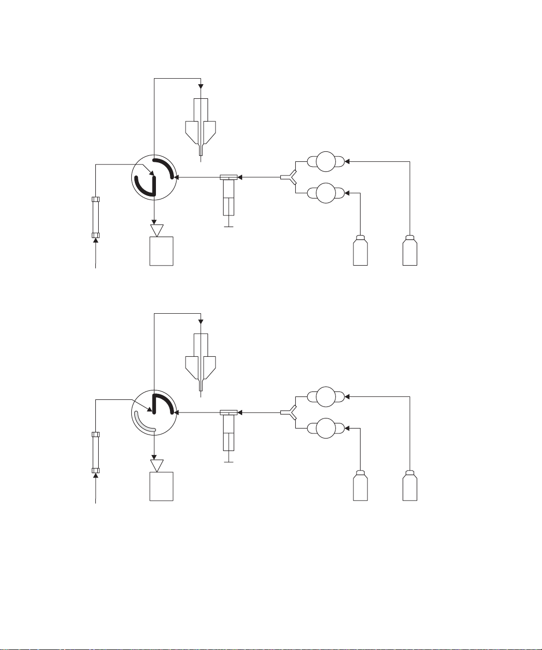
Diverter valve positions
Column and syringe in home position after power-up
After power-up, the flow path between the column and waste is open. The
syringe is empty, and the flow path between it and waste is open.
Waste
Column
Probe
Idle
Syringe
B
Off
A
Off
LC Waste
Reservoir A Reservoir B
LC position
In the LC position, the flow path between the LC and probe is open, and the
flow path between the syringe and waste is also open.
Probe
B
LC
Column
LC Waste
Idle
Syringe
Off
A
Off
Reservoir A Reservoir B
Preparing the IntelliStart fluidics system 2-11
Page 46
Infusion position in infusion mode
Probe
Infusion
Column
LC Waste
Infusion
Syringe
Reservoir A Reservoir B
B
Off
A
On
Combined position with LC flow and syringe in idle mode
Probe
Combined
Idle
B
Off
A
Off
Column
Syringe
LC Waste
2-12 Preparing the Waters TQ Detector for Operation
Reservoir A Reservoir B
Page 47

Waste position
In the waste position, both the LC flow and the infusion syringe flow are
directed to waste. The syringe mode can be only static or dispensing (that is,
never drawing).
Probe
Waste
Idle
Column
Syringe
LC Waste
Purging the infusion syringe
Whenever you replace a solution bott le, you sho uld purge t he inf usi on syringe
with the solution that you are going to use next.
Tip: Depending on the solutions used, the IntelliStart fluidics system can
require more then one purge cycle to minimize carryover.
To purge the infusion syringe:
1. In the ACQUITY UPLC Console system tree, expand TQ Detector.
2. Click Interactive Display.
B
Off
A
Off
Reservoir A Reservoir B
3. Select the re q u ir e d so l u ti o n reservoir.
4. Click to purge the system.
Tip: System purge takes approximately 2 minutes.
Preparing the IntelliStart fluidics system 2-13
Page 48

Rebooting the TQ Detector
Sometimes you might need to reboot the TQ Detector:
• When the Tune window fails to respond.
• When MassLynx fails to initialize.
• Immediately following software download.
Rebooting the TQ Detector by pressing the reset button
Tip: The reset button shuts down the electronics momentarily and causes the
TQ Detector to reboot.
To reboot the TQ Detector by pressing the reset button:
1. Open the TQ Detector’s front left door.
2. Press the red reset button on the top, left-hand side of the instrument.
TP02687
2-14 Preparing the Waters TQ Detector for Operation
Reset button
Page 49

Shutting down the TQ Detector
Recommendation: You should always leave the TQ Detect or in Operate mode
except when performing routine maintenance. It is not necessary to switch to
Standby mode. However, shutting down the TQ Detector is acceptable
provided that you consider warm-up time on restarting. If you do shut dow n
the TQ Detector, refer to the instructions in this section.
Caution: Buffers left in the system can precipitate and damage
instrument components.
Tip: Set system shutdown parameters in the Shutdown Editor. Consult the
MassLynx online Help for more information.
Putting the TQ Detector in Standby mode for overnight shutdown
You might want to shut down the instrument for a relatively brie f pe riod, like
overnight, while maintaining the LC flow.
To put the TQ Detector in Standby mode:
1. In the ACQUITY UPLC Console, click to stop the LC flow or, if
column flow is required, divert the LC flow to waste as follows:
a. In the ACQUITY UPLC Console system tree, expand TQ Detector.
b. Click Interactive Display.
c. Click the current diverter valve position label.
d. In the Select a Flow State dialog box, select Waste.
e. Click OK.
2. Click Standby to shut off heaters and voltages.
Tip: You can create a method to stop the gas flow or lower the
temperature. See the MassLynx online Help for more infor mation on
creating me t h ods.
Shutting down the TQ Detector 2-15
Page 50

Complete TQ Detector shutdown
To completely shut down the TQ Detector:
1. Put the TQ Detector in Standby mode.
See also: “Putting the TQ Detector in Standby mode for overnight
shutdown” on page 2-15.
2. In the ACQUITY UPLC Console, click API Gas .
3. Click Col Gas .
4. Click Control > Vent.
Result: The turbomolecular pump is switched off. When the
turbomolecular pump runs down to half its normal operating speed, the
vent valve opens and the instrument is automatically vented. The
operate LED changes from green to red and then turns off.
5. Exit MassLynx.
6. After the roughing pump shuts off, operate the power button (on the
front of the instrument) to power-off the TQ Detec tor.
Warning: The TQ Detecto r’s power switch does not isolate the
instrument from the main power supply. To isolate the
instrument, you must disconnect the power cable from the back
of the instrument.
7. Disconnect the power cable from the back of the TQ Detector.
8. Power-off all other instruments and the workstation.
Note: The fans inside some instruments run continuously, even after
you power-off the instruments.
2-16 Preparing the Waters TQ Detector for Operation
Page 51

Emergency TQ Detector shutdown
To shut down the TQ Detector in an emergency:
Warning: The TQ Detecto r’s power switch does not isolate the
instrument from the main power supply. To isolate the instrument,
you must disconnect the power cable from the back of the instrument.
Caution: Data can be lost during an emergency shutdown.
1. Operate the power button on the front of the TQ Detector .
2. Disconnect the power cable from the back of the TQ Detector.
Shutting down the TQ Detector 2-17
Page 52

2-18 Preparing the Waters TQ Detector for Operation
Page 53

3 ESI and ESCi Modes of
Operation
This chapter describes how to prepare the TQ Detector for the following
modes of operation:
• ESI (electrospray ionization)
• ESCi (combined electrospay and atmospheric pres sur e chemical
ionization)
If your system uses APCI mode, refer to Chapter 6 of the Waters TQ
Detector Operator’s Guid e.
Contents:
Topic Page
Introduction 3-2
Installing the ESI probe 3-2
Installing the corona pin 3-5
Optimizing the ESI probe for ESCi operation 3-7
Removing the corona pin 3-9
Removing the ESI probe 3-11
3-1
Page 54

Introduction
The ESI and ESCi ionization mode options use th e standar d ESI probe t hat i s
fitted to the instrument when it is shipped from the factory. For ESCi
operation, the corona pin is used in conjunction with the ESI pr obe. The
following sections explain how to install and remove t he ESI probe and cor ona
pin.
See also:
• “Electro sp ra y i o n iza t i o n (E SI)” on page 1-7.
• Table titled “Combined electrospray ionization and atmospheric
pressure chemical ionization (ESCi)” on page 1-7.
Installing the ESI probe
Required materials
Chemical-resistant, powder-free gloves
To install the ESI probe:
Warning: The ACQUITY UPLC system connections, ESI probe,
and source can be contaminated with biohazardous and/or toxic
materials. Always wear chemical-resistan t, powder-free gloves
while performing this procedure.
Warning: To avoid electric shock, ensure that the instrument is
suitably prepared before commencing this pr ocedure.
1. Prepare the instrument for working on the source.
See also: Chapter 5 of the Waters TQ Detector Operator’s Guide.
Warning: The source can be hot. To avoid burn injuries, take
great care while working with the instrument’s access door open.
2. Open the instrument’s access door.
3-2 ESI and ESCi Modes of Operation
Page 55

Warning: The ESI probe tip is sharp. To avoid puncture wounds,
handle the ESI probe with care.
3. Remove the protective sleeve, if fitted, from the ESI probe tip.
4. Ensure that the contacts o n the ESI probe align with the probe adjuster
assembly contacts, and carefully slid e the ESI probe into the hole in the
probe adjuster assembly.
ESI probe
Probe adjuster assembly
Probe adjuster
assembly contacts
TP02632
5. Secure the ESI probe by tightening the two thumbscrews.
See also: Figure titled “ESI probe mounted on the source enclosure,
showing the connections to the front panel” on page 3-4.
Installing the ESI probe 3-3
Page 56

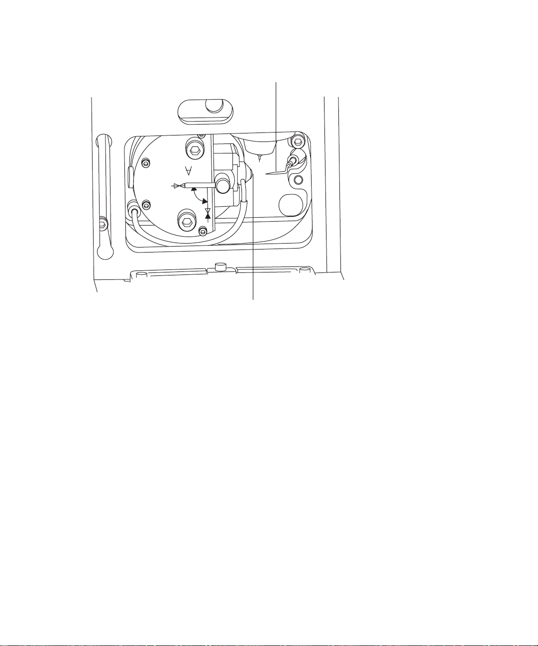
ESI probe mounted on the source enclosu re, showing th e connections
to the front panel:
Vernier prob e adju ste r
Nebulizer gas connection
Desolvation gas connection
ESI probe
electrical lead
Probe adjuster
assembly
electrical lead
Probe adjuster assembly
Thumbscrew
Diverter valve
ESI probe
6. Connect the ESI probe’s PTFE tube to the nebulizer gas connection.
7. Ensure that the probe adjuste r asse mbly’s e lectric al lead is con nected t o
the instrument’s probe connection.
8. Connect the ESI probe’s electrical lead to the instrument’s HV
connection.
Warning: To avoid electric shock, do not use stainless steel
tubing to connect the diverter valve to the ESI probe; use the
PEEK™ tubing supplied with the instrument.
9. Connect the diverter valve to the ESI probe; use tubing of the
appropriate internal diameter (ID).
Tip: Two tubes of different ID are supplied with the instrume nt.
Requirement: If you are replacing the tubing suppl ied with the
instrument, you must minimize the length of the tube connecting the
diverter valve to the ESI probe. This minimizes delays and dispersion.
10. Close the instrument’s access door.
3-4 ESI and ESCi Modes of Operation
Page 57

Installing the corona pin
Required materials
• Chemical-resistant, powder-free gloves
• Needle-nose pliers
• 80:20 acetonitrile/water
To install the corona pin:
Warning: The ACQUITY UPLC system connections, ESI probe,
and source can be contaminated with biohazardous and/or toxic
materials. Always wear chemical-resistan t, powder-free gloves
while performing this procedure.
Warning: To avoid electric shock, ensure that the instrument is in
Standby mode when commencing this procedure.
1. In the ACQUITY UPLC Console, click Stand by , and confirm that
the Operate indicator is not illuminated.
Warning: The source can be hot. To avoid burn injuries, take
great care while working with the instrument’s access door open.
2. Open the instrument’s access door.
Warning: The probe tip is sharp. To avoid puncture wounds , take
great care while working with the source enclosure door open if
an ESI probe is fitted.
Caution: Do not apply any downward force to the sourc e
enclosure door while the door is open.
3. Unlatch the source enclosure door’s handle and open the door.
Installing the corona pin 3-5
Page 58

4. Use the needle-nose pliers to remove the blanking plug from the corona
pin mounting contact.
Tip: Store the blanking plug in a safe location.
Corona pin mounting contact:
Corona pin mounting
contact blanking plug
TP02660
Warning: The corona pin tip is sharp. To avoid puncture wounds,
handle the corona pin with care.
Caution: To avoid damaging to the corona pin’s tip and bending
the pin, use the needle nose pliers to grip the corona pin at the
end that fits into the mounting contact.
5. Use the needle-nose pliers to fit the corona pin to the mounting contact.
Requirement: Ensure that the corona pin is securely mounted and that
its tip aligns with the sample cone orifice.
3-6 ESI and ESCi Modes of Operation
Page 59

Corona pin:
ESI probe tip
Corona pin
Sample cone tip
TP02695
6. Use the vernier probe adjuster to position the ESI probe tip so that it is
pointing approximately mid-way between the tips of the sample cone
and corona pin.
See also: Figure titled “ESI probe mounted on the source enclosure,
showing the connections to the front panel” on page 3-4.
7. Close the source enclosure door and fasten the handle.
8. Close the instrument’s access door.
Optimizing the ESI probe for ESCi operation
Required materials
80:20 acetonitrile/water
To optimize the ESI probe for ESCi operation:
1. In the MassLynx window, click MS Tune.
2. In the Tune window, click Setup > Inter-scan Setup.
3. In the Inter-scan Setup dialog box, click Reset to Defaults.
Optimizing the ESI probe for ESCi operation 3-7
Page 60

4. Click OK.
5. In the MassLynx Tune window, click Ion Mode > ESCi+.
6. Select box numbers 1 and 2, clear box numbers 3 and 4 (above the peak
display).
7. In row 1, set Ion Mode to ES.
8. In row 2, set Ion Mode to APcI.
9. In each row, set Mass to 42 and Span to 5.
10. Start an infusion of 80:20 acetonitrile/water.
11. Use the vernier probe adjuster to ensure that the ESI pr obe tip is
pointing approximately mid-way between the tips of the sample cone
and corona pin.
12. On the Tune window, observe the 42 Da peak in the ES+ and APcI+
peak displays, and increase the values of Capillary (kV) and Corona
[(µA) in the current mode or kV in the voltage mode] to prod uce the mo st
intense ESI+ and APcI+ signal.
13. Use the vernier probe adjuster to gradually move the probe
bi-directionally to determine the best position for both the ESI+ and
APcI+ signals.
Tip: You can find a position between the two modes that yields a
relatively optimized signal.
14. To determine whether you hav e discrete ionization in the ESI or APcI
mode, set the Capillary parameter to 0 kV and observe that little or no
signal remains in ESI mode. Then set the Corona parameter to 0 µA or
0 kV , and observe that little or no signal remains in APcI mode.
Result: The ESI probe is now optimized for ESCi mode.
Tip: If necessary, repeat the above procedure using the analyte of
interest, since ionization pot entials may vary with different samples.
3-8 ESI and ESCi Modes of Operation
Page 61

Removing the corona pin
Required materials
• Chemical-resistant, powder-free gloves
• Needle-nose pliers
To remove the corona pin:
Warning: The ACQUITY UPLC system connections, corona pin,
ESI probe, and source can be contaminated with biohazardous
and/or toxic materials. Always wear chemical-resistant,
powder-free gloves while performing this procedure.
Warning: To avoid electric shock, ensure that the instrument is in
Standby mode when commencing this procedure.
1. In the ACQUITY UPLC Console, click Stand by , and confirm that
the Operate indicator is not illuminated.
Warning: The source can be hot. To avoid burn injuries, take
great care while working with the instrument’s access door open.
2.
Open the instrument’s access door.
Warning: The probe tip is sharp. To avoid puncture wounds , take
great care while working with the source enclosure door open if
an ESI probe is fitted.
Caution: Do not apply any downward force to the sourc e
enclosure door while the door is open.
3. Unlatch the source enclosure door’s handle and open the door.
Removing the corona pin 3-9
Page 62

Warning: The corona pin tip is sharp. To avoid puncture wounds,
handle the corona pin with care.
Caution: To avoid damaging to the corona pin’s tip and bending
the pin, use the needle nose pliers to grip the corona pin at the
end that fits into the mounting contact.
4. Use the needle-nose pliers to remove the corona pin from its mounting
contact.
Tip: Store the corona pin in a safe location.
See also: Figure titled “Corona pin:” on page 3-7.
5. Use the needle-nose pliers to fit the blanking plug to the corona pin
mounting contact.
See also: Figure titled “Corona pin mounting contact:” on page 3-6.
6. Close the source enclosure door and fasten the handle.
7. Close the instrument’s access door.
3-10 ESI and ESCi Modes of Operation
Page 63
Removing the ESI probe
Required materials
Chemical-resistant, powder-free gloves
To remove the ESI probe:
Warning: The ACQUITY UPLC system connections, ESI probe,
and source can be contaminated with biohazardous and/or toxic
materials. Always wear chemical-resistan t, powder-free gloves
while performing this procedure.
Warning: To avoid electric shock, ensure that the instrument is
suitably prepared before commencing this pr ocedure.
1. Prepare the instrument for working on the source.
See also: Chapter 5 of the Waters TQ Detector Operator’s Guide.
Warning: The ESI probe and source can be hot. To avoid burn
injuries, ta ke g re a t care while wo rking with th e i n st rument’s
access door open.
2. Open the instrument’s access door.
3. Disconnect the diverter valve tubing from the ESI probe.
4. Disconnect the ESI probe’s electrical lead from the high voltage
connection.
5. Disconnect the ESI probe’s PTFE tube from the nebulizer gas
connection.
6. Undo the two thumbsc rews s ecur ing the ESI pro be to the probe adjust er
assembly.
Warning: The ESI probe tip is sharp. To avoid puncture wounds,
handle the probe with care.
7. Carefully remove the ESI probe from the probe adjuster assembly.
Removing the ESI probe 3-11
Page 64

8. If available, fit the protective sl eeve to the ESI probe tip.
9. Close the instrument’s access door.
3-12 ESI and ESCi Modes of Operation
Page 65

4 Operating the Waters TQ
Detector
This chapter is an introduction to operating your TQ Detector; it
explains these tasks:
• Setting-up your TQ Detector.
• Performing a sample tune.
• Developing instrument methods.
• Verifying the system.
Contents:
Topic Page
Setting-up the instrument 4-2
Performing a sample tune 4-7
Developing experiment me thods 4-9
Verifying the system using System QC 4-11
4-1
Page 66

Setting-up the instrument
The IntelliStart instrument setup calibrates the instrument and then, by
default, performs a sample tune. If calibration is unneces sary, you can
perform only a sample tune.
See also: “Performing a sample tune” on page 4-7.
Tip: Instrument setup need only be performed every three to six months,
depending on your usage requirements.
In the following example, sodium cesium iodide is used as the calibrant
solution and sulfadimethoxine the tune sample.
Tip: You can substitute solutions suitable for your requirements.
See also: The TQ Detector online Help for further details of IntelliStart.
Required materials
• Sodium cesium iodide solution (2 ng/µL)
• Sulfadimethoxine solution (100 pg/µL)
To prepare the IntelliStart fluidics system:
See also: “IntelliStart fluidics syst em operation” on page 1-17.
1. Ensure that IntelliStart fluidics system’s reservoir A is filled with
sodium cesium iodide solution.
2. Ensure that reservoir B is filled with sulfadimethoxine solution.
Requirement: Ensure that there is enough soluti on in each r eservoir f or
approximately 5 minutes of operation during the set-up procedure.
Recommendation: In general, place calibrant solution in reservoir A
and tune sample in reservoir B.
3. In the MassLynx window, click MS Console.
4. In the ACQUITY UPLC Console system tree, expand TQ Detector.
5. Click Interactive Display.
6. In the ACQUITY UPLC Console window, click the current flow rate.
7. In the Select Flow Rate dialog box, enter a 50 µL/min flow rate.
4-2 Operating the Waters TQ Detec tor
Page 67

8. Click OK.
9. Click to purge the system.
Tip: System purge takes approximately 2 minutes.
10. Repeat step 9.
Rationale: Purging the IntelliStart fluidics system twice ensures that
any traces of previously used solutions are removed from the system.
11. Click on the currently-selected reservoir display.
12. In the Select Reservoir dialog box, select the reservoir not currently
selected.
13. Click OK.
Result: The other reservoir is selected, and the system is purged.
14. When the purge finishes, click to purge the sys tem again.
To specify the instrument set-up parameters:
1. In the ACQUITY UPLC Console system tree, click TQ Detector.
2. Ensure that Ion Mode is ES+.
3. In the ACQUITY UPLC Console system tree, click IntelliStart.
4. Ensure that Instrument Setup is selected.
5. If you require system pre-checking, click Pre-checks.
Rationale: If Pre-checks is selected, when IntelliStart starts the
instrument set-up, it dete rmines whethe r t he existi ng cali brati on is stil l
valid. If so, it does not perform a full calibration but proc eeds to sample
tuning the instrument.
See also: TQ Detector online Help topic “IntelliStart flow diagram”.
6. Click Start to open the IntelliStart Setup Paramete rs dialog box.
7. In the Instrument Setup tab’s Reference drop-d own li st , click Naics.
Rationale: Naics is the calibration reference file for sodium ces i um
iodide when working in ES+ ion m ode.
Setting-up the instrument 4-3
Page 68

8. Click Fill from reference file.
Result: The default mass values appear in the In strument Tune Mas ses
text boxes.
Rule: You must click Fill from reference file every time you select a new
calibration reference file.
Instrument Setup Parameters dialog box Instrument Setup tab with
default parame ters:
Tip: You can use alternative reference solutions to calibrate at higher
masses.
9. The tune and calibration results are written to the files in the
Instrument Tune and Calibration text boxes; you can use the default
files, enter new names, or Browse for files.
4-4 Operating the Waters TQ Detec tor
Page 69

To specify the sample tune parameters:
1. In the IntelliStart Setup Parameters dialog box, click the Sample Tune
tab.
2. Click Copy Instrument Setup masses.
Rationale: The Tune Masses from the Instrument Setup tab are copied
into the Sample Tune Masses boxes.
Instrument Setup Parameters dialog box Sample Tune tab:
3. In the Tune text box, enter sulfadimethoxine.ipr.
Rationale: The sample tune results are written to this file.
Setting-up the instrument 4-5
Page 70

Instrument Setup Parameters dialog box Sample Tune tab with
example sample tune parameters:
To start instrument set-up:
1. Click Start .
Result: A message appears reminding you to ensure that the calibrant
solutions, calibration parameters and LC flow are set correctly.
2. Click OK.
Result: Instrument set-up starts. An autotune on the calibrant is
followed by automatic calibration. The ACQUITY UPLC Console
displays the progress of the setup.
4-6 Operating the Waters TQ Detec tor
Page 71

Example ACQUITY UPLC Console display during calibration:
IntelliStart creates tune and calibration files , which are saved as
specified on the Instrument Setup Parameters dialog box’s Instrument
Setup tab. Once calibration is complete, the sample tune starts on the
four masses defined in the Intell iStart Setup Parameters dialog box.
When the sample tune is complete, the results are written to the
Sulfadimethoxine.ipr file.
Performing a sample tune
In the following example, sulfadimethoxine is used as the tuning sample.
Required materials
Sulfadimethoxine solution (100 pg/µL)
To perform a sample tune:
1. Prepare the IntelliStart fluidics system with sulfadimethoxine solution
in reservoir B.
See also: “To prepare the IntelliStart fluidics system:” on page 4-2.
Performi ng a sample tune 4-7
Page 72

2. In the ACQUITY UPLC Console system tree, click TQ Detector.
3. Ensure that the Ion Mode is ES+.
4. In the ACQUITY UPLC Console system tree, click IntelliStart.
5. Clear the Instrument Setup check box.
6. If you require system pre-checking, click Pre-checks.
Rationale: If Pre-checks is selected, when IntelliStart starts the sampl e
tune, it determines whether the existing tune is still valid. If so, no
sample tune is performed.
See also: TQ Detector online Help topic “IntelliStart flow diagram”.
7. Click Start .
8. In the IntelliStart Setup Parameters dialog box’s Sample Tune tab,
specify the sample tune parameters as described in “To specify the
sample tune parameters:” on page 4-5.
9. Click Start .
Result: A message appears reminding you to ensure that the tune
solutions, tune parameters, and LC flow are set correctly.
10. Click OK.
Result: Sample tune starts. The ACQUITY UPLC Console displays the
progress of the tune. When the sample tune is complet e , the results are
written to the Sulfadimethoxine.ipr file.
4-8 Operating the Waters TQ Detec tor
Page 73

Developing experiment methods
IntelliStart allows you to automatically develop quantitative MRM or SIR
methods for compounds of interest. Up to four compounds can be handled in a
single process. Up to three transitions can be selected for each compound.In
this example, methods for sulfadimethoxine are create d.
Required materials
Sulfadimethoxine solution (100 pg/µL)
To create a method:
1. Prepare the IntelliStart fluidics system with sulfadimethoxine solution
in reservoir B.
See also: “To prepare the IntelliStart fluidics system:” on page 4-2.
2. In the ACQUITY UPLC Console system tree, click TQ Detector.
3. Ensure that the Ion Mode is ES+.
4. In the ACQUITY UPLC Console system tree, click IntelliStart.
5. Clear the Instrument Setup check box.
6. Click Develop Method.
7. If you require system pre-checking, click Pre-checks.
See also: TQ Detector online Help topic “IntelliStart flow diagram”.
8. Click Start .
9. In the IntelliStart Setup Parameters dialog box, click the Method
Develope r ta b .
Note: The masses, tune file and IntelliStart fluidics system parameters
already set in IntelliStart are used.
10. Select the parameters shown in the following figure.
Developing experiment methods 4-9
Page 74

Instrument Setup Parameters dialog box Method Developer tab:
In this case, Sulfadimethoxine.exp is the method file created.
The Validation pane selections save optimization data for validation
purposes and creates an autotune report file (Sulfadimethoxine.xml).
11. Click Start .
Result: A message appears reminding you to ensure that the sample
solutions, sample tune parameters and LC flow are set correctly.
12. Click OK.
Result: Method development starts. The ACQUITY UPLC Console
displays the progress of the method development. When the method
development is complete, the method is written to the
Sulfadimethoxine.exp file.
The Validation pane selection saves optimization data for validation
purposes, and creates an autotune report file (Sulfadimethoxine.xml).
A green check mark indicates a successful run; a red cross indicates a
failure.
4-10 Operating the Waters TQ Detector
Page 75

Verifying the system using System QC
The System QC function uses pre-defined LC/MS methods to test the system
by injecting a diagnostic sample on-column. The sample helps identify any
problems with the configured system by providing these data:
• Sensitivity (signal-to-noise rat io)
• Response (peak area, peak height)
• Chromatographic performance (peak width, retention time)
System QC can be activated in several ways:
• Manually, from the ACQUITY UPLC Console.
• Manually, as part of an ACQUITY UPLC Console Autotune sequence.
• Automatically, based on a scheduled date and time.
The following example shows you how to perform a manual verification.
See also: The MassLynx online Help for details of how to perform verifica tion
manually, as part of an Autotune sequence or automatically based on a
scheduled dat e and ti me.
Multiple injections are processed using the OpenLynx Application- Ma nager.
Measurements are reported for each chosen parameter across the repeat
analyses. If results are within user-defined tolerances, the LC/MS system is
ready to use.
The System Ready results are logged via the ACQUITY UPLC Console but
can also appear in a printed report. The raw data and OpenLynx browser
report are also stored for re cords.
Requirement: For System QC to work, OpenLynx must be installed with
MassLynx. OpenLynx is normally installed by default. If it has not been
installed, run the installation DVD, select Modify, and select OpenLynx when
prompted.
Before running System QC you need a suitable tune file, method f ile and inle t
file. You can use IntelliSt art to creat e a tune file and devel op a me thod fo r t he
sample you want to use for System QC.
See also: “Performing a sample tune” on page 4-7 and “Developing
experiment methods” on page 4-9.
Verifying the system using System QC 4-11
Page 76

An inlet file must be created independently.
See also: The MassLynx online Help.
Requirement: IntelliStart reads the tune, inlet, and method files from the
System QC project (SystemQC.pro). You must save the tune, inlet, and
method files to the Aqudb folder of the System QC project before performing
the verifica tion.
To perform a manual verification using System QC:
1. In the ACQUITY UPLC Console, click System QC.
2. Click Start .
Instrument Setup Parameters dialog box System QC tab with defau lt
parameters:
4-12 Operating the Waters TQ Detector
Page 77

3. In the IntelliStart Setup Parameters dialog box’s System QC tab, enter
the number of pre-run and run injections, the vial (that is , the position of
your sample in the Autosampler) and the injection volume.
Tip: At least two injections are required for a run, because some of the
validation parameters use standard deviation. A pre-run s ample is used
to clean and stabilize the system. You need not perform a pre-run prior
to a run.
Recommendation: Perform at least three injections.
4. Enter a tune, LC and inlet file, or use the browse button to select a file.
5. Select whether you are using a Scanning or SIR/MRM method. If using a
scanning method, enter a Mass on which to perform peak detection.
6. Select Print Report to print a report of the results.
7. Select the Acceptance parameters.
Instrument Setup Parameters dialog box System QC tab Acceptance
parameters :
Parameter Description
Retention Time Enter the expected retention time in the Set
Point box and enter the tolerance. If, for any
sample, the peak top is outside the range, the
test reflects a fa i l u re .
Peak Area The variation in peak area is calculated by
percentage Relative Standard Deviation
(%RSD).
%RSD = (Standard Deviation/Average Area) ×
100%
Enter a tolerance in %RSD, above which the
test reflects a fa i l u re .
Peak Height This is similar to Peak Area but using Peak
Height instead.
Peak Width Enter the expected peak wi dth in the Set Point
box and enter the tolerance. If, for any sam ple,
the peak width falls outside the range, the test
reflects a failure.
Verifying the system using System QC 4-13
Page 78

Instrument Setup Parameters dialog box System QC tab Acceptance
parameters (Continue d):
Parameter Description
Signal/Noise In Signal/Noise enter the signal-to-noise ratio
below which the test reflects a failure.
In Noise Range, enter the range in retention
time window over which the noise should be
calculated.
Select how the noise is calculated, either RMS
or Peak-to- P eak.
Tip: The signal is the peak height.
Tip: The calculations do not include injections where no peak was found.
For example, if only eight out of ten injections evidence detected peaks,
the acceptance test results would be based on eight values rather than
ten. However, the System QC process would always be marked as
“failed” due to the missing peaks.
8. Click Start .
Result: A message appears reminding you to ensure that the sample
vial, QC parameters and LC flow are set correctly.
9. Click OK.
Result: System QC starts. The ACQUITY UPLC Console displays its
progress.
4-14 Operating the Waters TQ Detector
Page 79

A Safety Advisories
Waters instruments display hazard symbols designed to alert you to the
hidden dangers of operating and maintaining the instruments. Their
corresponding user guides also include the hazard symbols, with
accompanying text statements describing the hazards and telling you
how to avoid them. This appendix presents all the safety symbols and
statements that apply to the entire line of Waters products.
Contents:
Topic Page
Warning symbols A-2
Caution symbol A-5
Warnings that apply to all Waters instruments A-5
Electrical and handling symbols A-13
A-1
Page 80

Warning symbols
Warning symbols alert you to the risk of death, injury, or seriously adverse
physiological reactions associated with an instrument’s use or misuse. Heed
all warnings when you install, repair, and operate Waters instruments.
Waters assumes no liability for the failure of those who install, repair, or
operate its instruments to comply with any safety precaution.
Task-specific hazard warnings
The following warning symbols alert you to risks that can arise when you
operate or maintain an instrument or instrument component. Such risks
include burn injuries, electric shocks, ultraviolet radiation exposures, and
others.
When the following symbols appear in a manual’s narratives or procedures ,
their accompanying text identifies the specif ic risk and explains how to avoid
it.
Warning: (Ge neral risk of danger. When this symbol appears on an
instrument, consult the instrument’s user documentation for
important safety-related information before you use the instrument.)
Warning: (Risk of burn injury from contacting hot surfaces.)
Warning: (R isk of electric shock.)
Warning: (Risk of fire)
Warning: (R isk of needle puncture.)
Warning: (Risk of injury caused by moving machinery.)
Warning: (Risk of exposure to ult raviolet r a di a ti o n . )
Warning: (Risk of contacting corrosive substances.)
Warning: (Risk of exposure to a toxic substance.)
A-2 Safety Advisories
Page 81

Warning: (Risk of personal exposure to laser radiation.)
Warning: (Risk of exposure to biological agents that can pose a serious
health threat.)
Warnings that apply to particular instruments, instrument components, and sample types
The following warnings can appear in the user manuals of particular
instrument s a nd on labels affixed to them or th e i r component parts.
Burst warning
This warning applies to Waters instruments fitted with nonmetallic tubing.
Warning: Pressurized nonmetallic, or po lymer, tubing can burst.
Observe these precautions when working around such tubing:
• Wear eye protection.
• Extinguish all nearby flames.
• Do not use tubing that is, or has been, stressed or kinked.
• Do not expose nonmetallic tubing to incompatible compounds like
tetrahydrofuran (THF) and nitric or sulfuric acids.
• Be aware that some compounds, like methylene chloride and
dimethyl sulfoxide, can cause nonmetallic tubing to swell, which
significantly reduces the pressure at which the tubing can rupt ure.
Mass spectrometer flammable solvents warning
This warning applies to instrum ents operated with flammable solvents.
Warning: Where significant quantities of flammable solvents are
involved, a continuous flow of nitrogen into the ion source is required
to prevent possible ignition in that enclosed sp ace.
Ensure that the nitrogen supply pressure never falls below 400 kPa
(4 bar, 58 psi) during an analysis in which flammable solvents are
used. Also ensure a gas-fail connection is connected to the HPLC
system so that the LC solvent flow stops if the nitrogen supply fails.
Warning symbols A-3
Page 82

Mass spectrometer shock hazard
This warning applie s t o al l Wa te r s m ass spectrometer s.
Warning: To avoid electric shock, do not remove the mass
spectrometer’s protective panels. The components they cover are not
user-serviceable.
This warning applies to certain instruments when they are in Operate mode.
Warning: High volt ages can be present at certain external surfaces of
the mass spectrometer when the instrument is in Operate mode. To
avoid non-lethal electric shock, make sure the instrument is in
Standby mode before touching areas marked with this high voltage
warning symbol.
Biohazard warning
This warning applies to Waters instruments that can be used to process
material that might contain biohazards: substances that contain biological
agents capable of producing harmful effects in humans.
Warning: Waters's instruments and software can be used to analyze or
process potentially infectious human-sourced products, inactivated
microorganisms, and other biological materials. To avoid infecti on with
these agents, assume that all biological fluids are infectious, observe
good laboratory practices and, consult your organization’s biohazard
safety representative regarding thei r proper use and handling. Sp ecific
precautions appear in the latest edition of the US National Institutes
of Health (NIH) publication, Biosafety in Microbiological and
Biomedical Laboratories (BMBL).
A-4 Safety Advisories
Page 83

Chemical hazard warning
This warning applies to Waters instruments that can process corrosive, toxic,
flammable, or other types of hazardous material .
Caution symbol
The caution symbol signifies that an instrument’s use or misuse can damage
the instrument or compromise a sample’s integrity. The following symbol and
its associated statement are typical of the kind that alert you to the risk of
damagin g t he instrument or sample.
Warning: Waters instruments can be used to analyze or
process potentially hazardous substances. To avoid injury
with any of these materials, familiarize yourself with the
materials and their hazards, observe Good Laborator y
Practices (GLP), and consult your organization’s safety
representative regarding proper use and handling.
Guidelines are provided in the latest edi tion of the National
Research Council's publication, Prudent Practices in the
Laboratory: Handling and Disposal of Chemica ls.
Caution: To avoid damage, do not use abrasives or sol vents to clean the
instrument’s case.
Warnings that apply to all Waters instruments
When operating this device, follow standard quality cont rol procedures and
the the equipment guidelines in this section.
Caution symbol A-5
Page 84

Attention: Changes or modifications to this unit not expressly approved by
the party responsible for c ompliance could void the user’s aut hority to operat e
the equipment.
Important: Toute modification sur cette unité n’ayant pas été expressément
approuvée par l’autorité respons able de la conformité à la réglementation
peut annuler le droit de l’utilisateur à exploiter l’équipement.
Achtung: Jedwede Änderungen oder Modifikationen an dem Gerät ohne die
ausdrückliche Genehmigung der für die ordnungsgemäße
Funktionstüchtigkeit verantwortlichen Personen kann zum Entzug der
Bedienungsbefugnis des Systems führen.
Avvertenza: eventuali modific he o al terazioni apportate a questa unità e
non espressamente approvate da un ente responsabile per la conformità
annulleranno l’autorità dell’utente ad operare l’apparecchiatura.
Atencion: cualquier cambio o modificación efectuado en esta unidad que no
haya sido expresamente aprobado por la parte respons able del cumplimiento
puede anular la autorización del usuario para utilizar el equipo.
A-6 Safety Advisories
Page 85

Warning: Use caution when working with any polymer tubing under
pressure:
• Always wear eye protection when near pressurized polymer tubing.
• Extinguish all nearby flames.
• Do not use tubing that has been severely stressed or kinked.
• Do not use nonmetallic tubing with tetrahydrofura n (THF) or concentrated
nitric or sulfuric acids.
• Be aware that methylene chloride and dimethyl sulfoxide cause
nonmetallic tubing to swell, whic h greatly reduces the rupture pressure of
the tubing.
Attention: Manipulez les tubes en polymère sous pression avec precaution:
• Portez systématiquement des lunettes de protection lorsque vous vous
trouvez à proximité de tubes en polymère pressurisés.
• Eteignez toute flamme se trouvant à proximité de l’instrument.
• Evitez d'utiliser des tubes sévèrement déformés ou endommagés.
• Evitez d'utiliser des tubes non métalliques avec du tétrahydrofurane
(THF) ou de l'acide sulfurique ou nitrique concentré.
• Sachez que le chlorure de méthylène et le diméthylesulfoxyde entr aînent le
gonflement des tuyaux non métalliques, ce qui réduit considérablement
leur pression de rupture.
Vorsicht: Bei der Arbeit mit Polymerschläuchen unter Druck ist besondere
Vorsicht angebracht:
• In der Nähe von unter D ruck stehenden Polymerschläuchen stets
Schutzbrille tragen.
• Alle offenen Flammen in der Nähe löschen.
• Keine Schläuche verwenden, die stark geknickt oder überbeansprucht
sind.
• Nichtmetallische Schläuche nicht für Tetrahydrofuran (THF) oder
konzentrierte Salpeter- oder Schwefelsäure verwenden.
• Durch Methylenchlorid und Dimethylsulfoxid können nichtmetallische
Schläuche quellen; dadurch wird der Berstdruck des Schlauches erheblich
reduziert.
Warnings that apply to all Waters instruments A-7
Page 86

Attenzione: prestare attenzione durante l’utilizzo dei tubi di polime ro
pressurizzati:
• Indossare sempre o cchiali da lavoro protet tivi nei pres si di tubi di polimero
pressurizzati.
• Estinguere ogni fonte di ig nizione circostante.
• Non utilizzare tubi soggetti che hanno subito sollecitazioni eccessive o son
stati incurvati.
• Non utilizzare tubi non metallici con tetraidrofurano (THF) o acido
solforico o nitrico concentrato.
• Tenere presente che il cloruro di metilene e il dimetilsolfossido provocano
rigonfiamento nei tubi non met allici, rid ucendo notevol mente la r esistenza
alla rottura dei tubi stessi.
Advertencia: se recomienda precaución cuando se trabaje con tubos de
polímero sometidos a presión :
• El usuario deberá protegerse siempr e los ojos cuando trabaje cerca de
tubos de polímero sometidos a presión.
• Si hubiera alguna llama las proximidades.
• No se debe trabajar con tubos que se hayan doblado o sometido a altas
presiones.
• Es necesario utilizar tubos de metal cuando se trabaje con
tetrahidrofurano (THF) o ácidos nítrico o sulfúrico concentrados.
• Hay que tener en cuenta que el cloruro de metileno y el sulfóxido de
dimetilo dilatan los tubos no metál icos, lo que reduce la presión de r uptura
de los tubos.
A-8 Safety Advisories
Page 87

Warnings that apply to all Waters instruments A-9
Page 88

Warning: The user shall be made aware that if the equipment is used in a
manner not specified by the manufacturer, the protection provided by the
equipment may be impaired.
Attention: L’utilisateur doit être informé que si le matériel est utilisé d’une
façon non spécifiée par le fabricant, la protection assurée par le matériel
risque d’être défectueuses.
Vorsicht: Der Benutzer wird darauf aufmerksam gemacht, dass bei
unsachgemäßer Verwenddung des Gerätes unter Umständen nicht
ordnungsgemäß funktionieren.
Attenzione: l’utente deve essere al corrente del fat to che, se
l’apparecchiatura viene usta in un modo specificato dal produttore, la
protezione fornita dall’apparecchiatura potrà essere invalidata.
Advertencia: el usuario deberá saber que si el equipo se utiliza de forma
distinta a la especificada por el fabricante, las medidas de protección del
equipo podrían ser insuficientes.
A-10 Safety Advisories
Page 89

Warning: To protect against fir e hazard, replace fuses with thos e of the same
type and rating.
Attention: Remplacez toujours les fusibles par d’ autres du même type et de
la même puissance afin d’éviter tout risque d’incendie.
Vorsicht: Zum Schutz gegen Feuergefahr die Sicherungen nur mit
Sicherungen des gleichen Typs und Nennwertes ersetzen.
Attenzione: per una buona protezione contro i rischi di incendio, sostituire i
fusibili con altri dello stesso tipo e amperaggio.
Advertencia: sustituya los fusibles por otros del mismo tipo y características
para evitar el riesgo de incendio.
Warnings that apply to all Waters instruments A-11
Page 90

Warning: To avoid pos sible elect rical shock, di sconnect the p ower cord before
servicing the instrument.
Attention: Afin d’éviter toute poss ibilité de commotion électrique,
débranchez le cordon d’alimentation de la prise avant d’effectuer la
maintenance de l’instrument.
Vorsicht: Zur Vermeidung von Stromschlägen sollte das Gerät vor der
Wartung vom Netz getrennt werden.
Attenzione: per evitare il rischio di scossa elettrica, scollegare il cavo di
alimentazione prima di svolgere la manutenzione dello strumento.
Precaución: para evitar descargas eléctricas, desenchufe el cable de
alimentación del instrumento antes de realizar cualquier reparación.
A-12 Safety Advisories
Page 91

Electrical and handling symbols
Electrical symbols
These can appear in inst rument user manuals and on the instrument’s front
or rear panels.
Electrical power on
Electrical power off
Standby
Direct current
Alternating current
Protective conductor terminal
Frame, or chassis, terminal
Fuse
Recycle symbol: Do not dispose in municipal waste.
Electrical and handling symbols A-13
Page 92
Handling symbols
These handling symbols and their associ ated t ext can app ear on lab els affixed
to the outer packaging of Waters instrument and component shipments.
Keep upr ight!
Keep dry!
Fragile!
Use no hooks!
A-14 Safety Advisories
 Loading...