

Page 1

Waters SYNAPT G2 Mass
Spectrometry System
Operator’s Overview and Maintenance Guide
Revision A
Copyright © Waters Corporation 2009
All rights reserved
Page 2

Copyright notice
© 2009 WATERS CORPORATION. PRINTED IN THE UNITED STATES OF
AMERICA AND IN IRELAND. ALL RIGHTS RESERVED. THIS
DOCUMENT OR PARTS THEREOF MAY NOT BE REPRODUCED IN ANY
FORM WITHOUT THE WRITTEN PERMISSION OF THE PUBLISHER.
The information in this document is subject to change without notice and
should not be construed as a commitment by Waters Corporation. Waters
Corporation assumes no responsibility for any errors that may appear in this
document. This document is believed to be complete and accurate at the time
of publication. In no event shall Waters Corporation be liable for incidental or
consequential damages in connection with, or arising from, its use.
Trademarks
ACQUITY, ACQUITY UPLC, Connections Insight, ESCi, UPLC, and Waters
are registered trademarks of Waters Corporation. IntelliStart, LockSpray,
MassLynx, NanoFlow, NanoLockSpray, QuanTof, SYNAPT, T-Wave, “THE
SCIENCE OF WHAT'S POSSIBLE.”, Triwave, and ZSpray are trademarks of
Waters Corporation.
GELoader is a registered trademark of Cell Technology.
Swagelok and snoop are registered trademarks of Swagelok Company.
PEEK is a trademark of Victrex plc.
Viton is a registered trademark of DuPont Performance Elastomers.
Other registered trademarks or trademarks are the sole property of their
respective owners.
ii
Page 3

Customer comments
Waters’ Technical Communications department invites you to tell us of any
errors you encounter in this document or to suggest ideas for otherwise
improving it. Please help us better understand what you expect from our
documentation so that we can continuously improve its accuracy and
usability.
We seriously consider every customer comment we receive. You can reach us
at tech_comm@waters.com.
iii
Page 4

Contacting Waters
Contact Waters® with enhancement requests or technical questions regarding
the use, transportation, removal, or disposal of any Waters product. You can
reach us via the Internet, telephone, or conventional mail.
Waters contact information
Contacting medium Information
Internet The Waters Web site includes contact
Telephone and fax From the USA or Canada, phone 800
Conventional mail Waters Corporation
information for Waters locations worldwide.
Visit www.waters.com.
252-HPLC, or fax 508 872 1990.
For other locations worldwide, phone and fax
numbers appear in the Waters Web site.
34 Maple Street
Milford, MA 01757
USA
Safety considerations
Some reagents and samples used with Waters instruments and devices can
pose chemical, biological, and radiological hazards. You must know the
potentially hazardous effects of all substances you work with. Always follow
Good Laboratory Practice, and consult your organization’s safety
representative for guidance.
When you develop methods, follow the “Protocol for the Adoption of Analytical
Methods in the Clinical Chemistry Laboratory,” American Journal of Medical
Technology, 44, 1, pages 30–37 (1978). This protocol addresses good operating
procedures and the techniques necessary to validate system and method
performance.
iv
Page 5

Considerations specific to the SYNAPT G2 MS system
Solvent leakage hazard
The source exhaust system is designed to be robust and leak-tight. Waters
recommends you perform a hazard analysis, assuming a maximum leak into
the laboratory atmosphere of 10% LC eluate.
Warning:
• To confirm the integrity of the source exhaust system, renew
the source O-rings at intervals not exceeding one year.
• To avoid chemical degradation of the source O-rings, which can
withstand exposure only to certain solvents (see “Solvents used
to prepare mobile phases” on page C-3), determine whether any
solvents you use that are not listed are chemically compatible
with the composition of the O-rings.
Flammable solvents hazard
Warning: To prevent the ignition of accumulated solvent vapors inside
the source, maintain a continuous flow of nitrogen through the source
whenever significant amounts of flammable solvents are used during
instrument operation.
Never let the nitrogen supply pressure fall below 400 kPa (4 bar, 58 psi)
during analyses that require flammable solvents. Connect to the LC output
with a gas-fail connector to stop the LC solvent if the nitrogen supply fails.
v
Page 6

High temperature hazard
Warning: To avoid burn injuries, avoid touching the source enclosure
with your hand when operating or servicing the instrument.
Mass spectrometer high temperature hazard
Source ion block assembly
vi
Page 7

Hazards associated with removing an instrument from service
Warning: To avoid personal contamination with
biohazardous or toxic materials, wear chemical-resistant
gloves during all phases of instrument decontamination.
Warning: To avoid puncture injuries, handle syringes, fused silica lines,
and borosilicate tips with care.
When you remove the instrument from use to repair or dispose of it, you must
decontaminate all of its vacuum areas. These are the areas in which you can
expect to encounter the highest levels of contamination:
• Source interior
• Waste tubing
• Exhaust system
• Rotary pump oil (where applicable)
The need to decontaminate other vacuum areas of the instrument depends on
the kinds of samples the instrument analyzed and their levels of
concentration. Do not dispose of the instrument or return it to Waters for
repair until the authority responsible for approving its removal from the
premises specifies the extent of decontamination required and the level of
residual contamination permissible. Management must also prescribe the
method of decontamination to be used and the appropriate protection for
personnel undertaking the decontamination process.
You must handle items such as syringes, fused silica lines, and borosilicate
tips used to carry sample into the source area in accordance with laboratory
procedures for contaminated vessels and sharps. To avoid contamination by
carcinogenic, toxic, or biohazardous substances, you must wear
chemical-resistant gloves when handling or disposing of used oil.
Safety advisories
Consult Appendix A for a comprehensive list of warning and caution
advisories.
vii
Page 8

Operating this instrument
When operating this instrument, follow standard quality-control (QC)
procedures and the guidelines presented in this section.
Applicable symbols
Symbol Definition
Confirms that a manufactured product complies
with all applicable European Community
directives
ABN 49 065 444 751
Audience and purpose
This guide is for operators of varying levels of experience. It gives an overview
of the instrument, and explains how to prepare it, change its modes of
operation, and maintain it.
Intended use
Waters designed this instrument to be used as a research tool to deliver
authenticated, exact-mass measurement. It is not for use in diagnostic
procedures.
Australia C-Tick EMC Compliant
Confirms that a manufactured product complies
with all applicable United States and Canadian
safety requirements
This product has been tested to the requirements
of CAN/CSA-C22.2 No. 61010-1, second edition,
including Amendment 1, or a later version of the
same standard incorporating the same level of
testing requirements
viii
Page 9

Calibrating
To calibrate LC systems, follow acceptable calibration methods using at least
five standards to generate a standard curve. The concentration range for
standards should include the entire range of QC samples, typical specimens,
and atypical specimens.
When calibrating mass spectrometers, consult the calibration section of the
operator’s guide for the instrument you are calibrating. In cases where an
overview and maintenance guide, not operator’s guide, accompanies the
instrument, consult the instrument’s online Help system for calibration
instructions.
Quality control
Routinely run three QC samples that represent subnormal, normal, and
above-normal levels of a compound. Ensure that QC sample results fall within
an acceptable range, and evaluate precision from day to day and run to run.
Data collected when QC samples are out of range might not be valid. Do not
report these data until you are certain that the instrument performs
satisfactorily.
ISM classification
ISM Classification: ISM Group 1 Class A
This classification has been assigned in accordance with CISPR 11 Industrial
Scientific and Medical (ISM) instruments requirements. Group 1 products
apply to intentionally generated and/or used conductively coupled
radio-frequency energy that is necessary for the internal functioning of the
equipment. Class A products are suitable for use in commercial, (that is,
nonresidential) locations and can be directly connected to a low voltage,
power-supply network.
ix
Page 10

EC Authorized Representative
Waters Corporation (Micromass UK Ltd.)
Floats Road
Wythenshawe
Manchester M23 9LZ
United Kingdom
Telephone: +44-161-946-2400
Fax: +44-161-946-2480
Contact: Quality manager
x
Page 11

Table of Contents
Copyright notice ................................................................................................... ii
Trademarks ............................................................................................................ ii
Customer comments ............................................................................................ iii
Contacting Waters ............................................................................................... iv
Safety considerations .......................................................................................... iv
Considerations specific to the SYNAPT G2 MS system .................................... v
Safety advisories............................................................................................... vii
Operating this instrument .............................................................................. viii
Applicable symbols .......................................................................................... viii
Audience and purpose...................................................................................... viii
Intended use..................................................................................................... viii
Calibrating .......................................................................................................... ix
Quality control .................................................................................................... ix
ISM classification ................................................................................................. ix
ISM Classification: ISM Group 1 Class A ......................................................... ix
EC Authorized Representative .......................................................................... x
1 System Overview .................................................................................... 1-1
Waters SYNAPT G2 MS .................................................................................... 1-2
SYNAPT G2 MS UPLC/MS/MS systems ........................................................ 1-2
ACQUITY UPLC SYNAPT G2 MS UPLC/MS/MS system............................ 1-2
nanoACQUITY UPLC SYNAPT G2 MS nanoUPLC/MS/MS system ........... 1-3
Software .............................................................................................................. 1-3
IntelliStart ....................................................................................................... 1-3
MassLynx ......................................................................................................... 1-4
Instrument Console ......................................................................................... 1-4
Table of Contents xi
Page 12

Instrument sources ........................................................................................... 1-5
LockSpray source and ionization modes......................................................... 1-5
NanoLockSpray source.................................................................................... 1-7
Dual-mode ionization source........................................................................... 1-9
Matrix-assisted laser desorption ionization ................................................... 1-9
IntelliStart Fluidics system ............................................................................ 1-9
Overview........................................................................................................... 1-9
IntelliStart Fluidics physical layout............................................................. 1-10
System operation ........................................................................................... 1-11
Ion optics ........................................................................................................... 1-12
Analyzers ........................................................................................................... 1-13
Quadrupole..................................................................................................... 1-13
Triwave technology........................................................................................ 1-14
TOF analyzer ................................................................................................. 1-15
Mass spectrometer configuration ............................................................... 1-17
Triwave device ............................................................................................... 1-17
TOF................................................................................................................. 1-17
Leak sensors ..................................................................................................... 1-18
Vacuum system ................................................................................................ 1-18
Controls on the instrument’s rear panel ................................................... 1-19
2 Starting Up and Shutting Down the Mass Spectrometer ............. 2-1
Starting the mass spectrometer .................................................................... 2-2
Calibration information................................................................................... 2-3
Flow rates for the ACQUITY UPLC SYNAPT G2 MS
UPLC/MS/MS system................................................................................ 2-3
Preparing the IntelliStart Fluidics system ................................................. 2-4
Installing the vials........................................................................................... 2-4
Purging the pump ............................................................................................ 2-5
Shutting down the mass spectrometer ........................................................ 2-6
Putting the mass spectrometer in Standby mode .......................................... 2-6
Fully shutting down the mass spectrometer.................................................. 2-6
xii Table of Contents
Page 13

Rebooting the embedded PC .......................................................................... 2-7
3 Configuring the LockSpray Source ................................................... 3-1
Configuring the LockSpray source ............................................................... 3-2
Configuring for ESI mode ............................................................................... 3-2
Installing the ESI probe .................................................................................. 3-2
Removing the ESI probe.................................................................................. 3-7
Installing the ESI small bore capillary option ........................................... 3-8
Configuring for APCI mode .......................................................................... 3-14
Installing the APCI probe ............................................................................. 3-14
Installing the corona pin in the source......................................................... 3-18
Removing the corona pin from the source .................................................... 3-18
Removing the APCI probe ............................................................................. 3-18
Configuring for ESCi mode .......................................................................... 3-19
Optimizing the ESI probe for ESCi operation.............................................. 3-19
Installing the corona pin in the source......................................................... 3-19
Removing the corona pin from the source .................................................... 3-19
4 Configuring the NanoLockSpray source .......................................... 4-1
Overview of the NanoLockSpray source ..................................................... 4-2
Sample sprayer ................................................................................................ 4-3
LockSpray sprayer........................................................................................... 4-3
NanoFlow gas supply....................................................................................... 4-4
Purge gas.......................................................................................................... 4-4
Sprayer platform adjuster assembly............................................................... 4-4
Selecting and Configuring the NanoLockSpray source .......................... 4-4
Deploying the sprayer platform adjuster assembly ................................. 4-5
Adjusting the sprayer tip position ................................................................ 4-6
Setting up the camera ...................................................................................... 4-7
Table of Contents xiii
Page 14

Optional glass capillary sprayer ................................................................... 4-8
Installing the glass capillary sprayer ............................................................. 4-8
Fitting and loading the glass capillary........................................................... 4-9
5 Maintenance Procedures ..................................................................... 5-1
Maintenance schedule ..................................................................................... 5-3
Spare parts ......................................................................................................... 5-4
Troubleshooting using Connections Insight .............................................. 5-5
Safety and handling ......................................................................................... 5-6
Preparing the instrument for work performed on its source ................ 5-7
Removal and refitting of the source enclosure .......................................... 5-8
Removing the source enclosure from the instrument.................................... 5-8
Fitting the source enclosure to the instrument............................................ 5-11
Installing and removing the corona pin .................................................... 5-12
Installing the corona pin in the source......................................................... 5-12
Removing the corona pin from the source .................................................... 5-14
Operating the source isolation valve ......................................................... 5-15
Removing O-rings and seals ......................................................................... 5-17
Cleaning the mass spectrometer case ........................................................ 5-18
Emptying the nitrogen exhaust trap bottle .............................................. 5-19
Cleaning the source components ................................................................ 5-21
Cleaning the sampling cone assembly ....................................................... 5-21
Removing the sampling cone assembly from the source ............................. 5-21
Disassembling the sampling cone assembly................................................. 5-23
Cleaning the sample cone and cone gas nozzle ............................................ 5-26
Assembling the sampling cone assembly...................................................... 5-28
Fitting the sampling cone assembly to the source ....................................... 5-29
Cleaning the extraction cone ....................................................................... 5-31
Removing the ion block assembly from the source assembly...................... 5-31
Removing the extraction cone from the ion block ........................................ 5-33
xiv Table of Contents
Page 15

Cleaning the extraction cone......................................................................... 5-34
Fitting the extraction cone to the ion block.................................................. 5-36
Fitting the ion block assembly to the source assembly................................ 5-37
Cleaning the ion block assembly ................................................................. 5-38
Disassembling the source ion block assembly.............................................. 5-38
Cleaning the ion block components .............................................................. 5-45
Assembling the source ion block assembly................................................... 5-47
Cleaning the source T-Wave ion guide assembly .................................... 5-49
Removing the T-Wave ion guide assembly from the source assembly........ 5-49
Disassembling the T-Wave ion guide assembly ........................................... 5-51
Cleaning the T-Wave ion guide assembly aperture plate............................ 5-52
Cleaning the T-Wave ion guide..................................................................... 5-52
Assembling the T-Wave ion guide assembly ................................................ 5-54
Fitting the T-Wave ion guide assembly, PEEK ion block support,
and ion block assembly to the source assembly ..................................... 5-54
Replacing the ESI probe tip and gasket .................................................... 5-55
Removing the ESI probe tip and gasket ....................................................... 5-56
Fitting the ESI probe tip and gasket............................................................ 5-58
Replacing the ESI probe sample capillary ............................................... 5-59
Removing the existing capillary.................................................................... 5-59
Installing the new capillary .......................................................................... 5-64
Cleaning the APCI probe tip ........................................................................ 5-67
Replacing the APCI probe sample capillary ............................................ 5-68
Removing the existing capillary.................................................................... 5-68
Installing the new capillary .......................................................................... 5-71
Replacing the LockSpray probe capillary ................................................ 5-74
Removing the existing capillary.................................................................... 5-74
Installing the new capillary .......................................................................... 5-77
Replacing the NanoLockSpray reference probe capillary ................... 5-78
Removing the NanoLockSpray reference probe ........................................... 5-78
Installing the new TaperTip and capillary................................................... 5-80
Table of Contents xv
Page 16

Cleaning or replacing the corona pin ........................................................ 5-83
Replacing the APCI probe heater ............................................................... 5-84
Removing the APCI probe heater ................................................................. 5-84
Fitting the new APCI probe heater .............................................................. 5-86
Replacing the ion block source heater ...................................................... 5-87
Replacing the LockSpray source assembly seals .................................... 5-91
Removing the probe adjuster assembly probe and source
enclosure seals ......................................................................................... 5-91
Fitting the new source enclosure seals......................................................... 5-93
Replacing the mass spectrometer’s air filter ........................................... 5-95
Replacing the air filter................................................................................... 5-95
Replacing the IntelliStart Fluidics tubing ............................................... 5-98
Removing the IntelliStart Fluidics tubing ................................................... 5-99
Plumbing the IntelliStart Fluidics LockSpray system ................................ 5-99
Plumbing the IntelliStart Fluidics sample delivery system...................... 5-108
A Safety Advisories .................................................................................. A-1
Warning symbols ............................................................................................... A-2
Task-specific hazard warnings........................................................................ A-2
Specific warnings ............................................................................................. A-3
Caution symbol .................................................................................................. A-5
Warnings that apply to all Waters instruments ......................................... A-6
Electrical and handling symbols ................................................................. A-11
Electrical symbols .......................................................................................... A-11
Handling symbols .......................................................................................... A-12
B External Connections .......................................................................... B-1
Mass spectrometer external wiring and vacuum connections ............. B-2
Connecting the Edwards oil-free roughing pump ................................... B-3
Making the electrical connections to the Edwards oil-free
roughing pump........................................................................................... B-7
xvi Table of Contents
Page 17

Connecting to the nitrogen gas supply ....................................................... B-7
Connecting to the collision cell gas supply ............................................... B-9
Connecting the nitrogen exhaust line ...................................................... B-10
Connecting the liquid waste line ............................................................... B-13
Input/output signal connectors .................................................................. B-15
Signal connections ......................................................................................... B-18
Connecting the workstation (system without ACQUITY UPLC) ........ B-21
Connecting Ethernet cables (system with ACQUITY UPLC) .............. B-21
Connecting to the electricity source ......................................................... B-22
Connecting the NanoLockSpray source camera .................................... B-23
Installing the camera driver software .......................................................... B-23
C Materials of construction and compliant solvents ....................... C-1
Preventing contamination ............................................................................. C-2
Items exposed to solvent ................................................................................ C-2
Solvents used to prepare mobile phases .................................................... C-3
Index ..................................................................................................... Index-1
Table of Contents xvii
Page 18

xviii Table of Contents
Page 19

1 System Overview
This chapter describes the instrument, including its controls, sources, and
IntelliStart™ Fluidics system.
Contents
Topic Page
Waters SYNAPT G2 MS 1-2
SYNAPT G2 MS UPLC/MS/MS systems 1-2
Software 1-3
Instrument sources 1-5
IntelliStart Fluidics system 1-9
Ion optics 1-12
Analyzers 1-13
Mass spectrometer configuration 1-17
Leak sensors 1-18
Vacuum system 1-18
Controls on the instrument’s rear panel 1-19
1-1
Page 20

Waters SYNAPT G2 MS
The SYNAPT™ G2 Mass Spectrometry (MS) system is a hybrid,
quadrupole/orthogonal acceleration, time-of-flight (oa-TOF) mass
spectrometer controlled by MassLynx™ software.
Either of the following high-performance, ZSpray™, dual-orthogonal, API
sources is fitted as standard equipment:
• LockSpray™ ESI/APCI/ESCi
• NanoLockSpray™ ESI source (see page 1-7).
You can also use the following optional sources:
• Dual-mode APPI/APCI (see the Waters Dual-Mode (APPI/APCI) Source
for Xevo and SYNAPT G2 Instruments Operator’s Guide).
•MALDI (see the Waters MALDI SYNAPT G2 Mass Spectrometry System
Overview and Maintenance Guide).
For the instrument’s specifications, see the Waters SYNAPT G2 MS Site
Preparation Guide.
®
source (see page 1-5).
SYNAPT G2 MS UPLC/MS/MS systems
The Waters SYNAPT G2 MS is compatible with the ACQUITY UPLC® and
nanoACQUITY UPLC
refer to the documentation relevant to your LC system.
®
systems. If you are not using either of those systems,
ACQUITY UPLC SYNAPT G2 MS UPLC/MS/MS system
The ACQUITY UPLC SYNAPT G2 MS UPLC®/MS/MS system includes an
ACQUITY UPLC system and the Waters SYNAPT G2 MS fitted with the
LockSpray ESI/APCI/ESCi source.
The ACQUITY UPLC system includes a binary solvent manager, sample
manager, column heater, sample organizer, detectors, and a specialized
ACQUITY UPLC column. MassLynx software controls the system.
1-2 System Overview
Page 21

See also: The ACQUITY UPLC System Operator’s Guide or Controlling
Contamination in LC/MS Systems (part number 715001307). You can find the
latter document online at http://www.waters.com; click Services and Support
> Support.
nanoACQUITY UPLC SYNAPT G2 MS nanoUPLC/MS/MS system
The nanoACQUITY UPLC SYNAPT G2 MS nanoUPLC/MS/MS system
includes a nanoACQUITY UPLC system and the Waters SYNAPT G2 MS
fitted with the NanoLockSpray source.
The nanoACQUITY UPLC system includes a binary solvent manager,
auxiliary solvent manager, sample manager, column heater, sample
organizer, detectors, and a specialized nanoACQUITY UPLC column.
MassLynx software controls the system.
See also: The nanoACQUITY UPLC System Operator’s Guide or Controlling
Contamination in LC/MS Systems (part number 715001307). You can find the
latter document online at http://www.waters.com; click Services and Support
> Support.
Software
IntelliStart
IntelliStart software monitors the mass spectrometer’s performance and
reports when the instrument is ready for use. The software automatically
mass calibrates the instrument and displays performance readbacks.
Integrated with MassLynx software and Instrument Console software,
IntelliStart software enables simplified setup of the system for use in routine
analytical and open-access applications. See the mass spectrometer’s online
Help for further details on IntelliStart technology.
The IntelliStart Fluidics system is built into the mass spectrometer. It
delivers sample directly to the MS probe from the LC column or from three
integral vials. The vials can also deliver sample through direct or combined
infusion so that you can optimize instrument performance at analytical flow
rates. An additional reservoir contains solvent for the automated flushing of
the solvent delivery system. For further details, see “IntelliStart Fluidics
system” on page 1-9.
Software 1-3
Page 22

MassLynx
MassLynx software, version 4.1, controls the mass spectrometer. A
high-performance application, it acquires, analyzes, manages, and distributes
mass spectrometry, ultraviolet (UV), evaporative light scattering, and analog
data.
MassLynx enables these major operations:
• Configuring the instrument
• Creating LC and MS/MS methods that define operating parameters for a
• Using IntelliStart software to tune and mass calibrate the mass
• Running samples
• Monitoring the run
• Acquiring data
• Processing data
•Reviewing data
• Printing data
See the MassLynx 4.1 user documentation and online Help for more
information on installing and using MassLynx software.
run
spectrometer
Instrument Console
Using Instrument Console software, you configure settings, monitor
performance, run diagnostic tests, and maintain the system and its modules.
The software functions independently of MassLynx software and does not
recognize or control the data systems.
See the Instrument Console system online Help for details.
1-4 System Overview
Page 23
Instrument sources
LockSpray source and ionization modes
The LockSpray source uses lock-mass correction to acquire exact mass data.
The sample is introduced into the source through a probe. A lock-spray flow,
containing a compound of known mass, flows through a separate ESI probe
(the LockSpray sprayer). An oscillating baffle allows the sprays to be analyzed
as two separate data functions. The lock-mass correction, calculated from the
lock-spray data, is then applied to the sample data set.
You can use the LockSpray source with the following ionization modes:
•ESI
•APCI
•ESCi
• nanoSpray
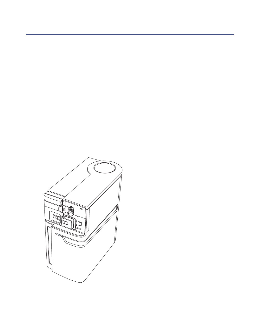
SYNAPT G2 MS fitted with LockSpray source
Instrument sources 1-5
Page 24

Electrospray ionization
In electrospray ionization (ESI), a strong electrical charge is applied to the
eluent as it emerges from a nebulizer. The droplets that compose the resultant
aerosol undergo a reduction in size (solvent evaporation). As solvent continues
to evaporate, the charge density increases until the droplet surfaces eject ions
(ion evaporation). The ions can be singly or multiply charged.
To operate the LockSpray source in ESI mode, you fit the source enclosure
with an ESI probe.
The standard ESI probe capillary accommodates flow rates of up to 2 mL/min
making it suitable for LC applications in the range 100 µL/min to 2 mL/min.
To reduce peak broadening for lower-flow rate LC applications, such as 1-mm
UPLC columns, use the optional small-bore capillary option, which can
accommodate a maximum flow rate of up to 200 µL/min.
Atmospheric pressure chemical ionization
Atmospheric pressure chemical ionization (APCI) produces singly charged
protonated or deprotonated molecules for a broad range of nonvolatile
samples.
To operate the LockSpray source in APCI mode, you fit the source enclosure
with a corona pin and an APCI probe. Mobile phase from the LC column
enters the probe, where it is pneumatically converted to an aerosol, rapidly
heated, and vaporized or gasified at the probe tip.
APCI mode
APCI probe
Sample cone
1-6 System Overview
Corona pin
Page 25

Hot gas from the APCI probe passes between the sample cone and the corona
pin. Mobile phase molecules rapidly react with ions generated by the corona
discharge to produce stable reagent ions. Sample molecules introduced into
the mobile phase react with the reagent ions at atmospheric pressure and
typically become protonated (in the positive ion mode) or deprotonated (in the
negative ion mode). The sample and reagent ions then pass through the
sample cone and into the mass spectrometer.
Combined electrospray and atmospheric pressure chemical
ionization
In combined electrospray and atmospheric pressure chemical ionization
(ESCi) mode, the standard ESI probe is used in conjunction with a corona pin
to allow alternating acquisition of ESI and APCI ionization data, facilitating
high-throughput processing and wider compound coverage.
NanoLockSpray source
The NanoLockSpray source allows electrospray ionization performed in the
flow rate range of 5 to 1000 nL/min.
For a given sample concentration, the ion currents for similar experiments
approximate to those in normal flow rate electrospray. However, because
sample consumption is greatly reduced, the sensitivity gains are significant
when you adopt similar scan parameters. Lock-mass correction with the
NanoLockSpray source works in the same way as the LockSpray source does
with ESI.
The NanoLockSpray source enclosure consists of a sprayer—either universal,
borosilicate glass capillary, or CE (see below)—mounted on a ZSpray,
three-axis manipulator.
The combined unit is mounted on the NanoFlow™ stage, which runs on a pair
of guide rails, with two defined positions.
A light within the source provides illumination for the spray, which you can
observe using the video camera mounted on the corner of the source housing.
Instrument sources 1-7
Page 26

SYNAPT G2 MS fitted with NanoLockSpray source
The following options are available for the spraying capillary:
• Universal NanoFlow nebulizer sprayer.
This option, for flow injection or coupling to nanoACQUITY UPLC, uses
a pump to regulate the flow rate as low as 100 nL/min.
• Borosilicate glass capillary NanoFlow (nanovials).
This option uses metal-coated glass capillaries, which allow the lowest
flow rates. Usable for one sample only, they must then be discarded.
• NanoFlow capillary electrophoresis (CE) sprayer.
This option uses a make-up liquid at the CE capillary tip, which allows a
stable electrospray to occur. The make-up flow rate is less than
1µL/min.
1-8 System Overview
Page 27

Dual-mode ionization source
Atmospheric pressure photoionization (APPI) uses photons generated by a
discharge UV lamp (~10.2 eV) to produce sample ions from vaporized LC
eluent. Direct photoionization of the sample molecule occurs when the photon
energy exceeds the ionization potential of the sample molecule.
The optional dual-mode (APPI/APCI) ionization source incorporates an APPI
source enclosure used in conjunction with a standard APCI probe. You can
operate the source in APPI, APCI, or dual-mode, which switches rapidly
between ionization modes, facilitating high-throughput analyses.
See also: The Waters SYNAPT G2 Dual-mode Ionization Source Operator’s
Guide.
Matrix-assisted laser desorption ionization
The matrix-assisted laser desorption ionization (MALDI) interface enables
rapid, tool-free switching between API and MALDI modes. A motorized stage
moves the MALDI source into position.
See also: The Waters MALDI SYNAPT G2 MS System Operator’s Guide.
IntelliStart Fluidics system
Overview
The IntelliStart Fluidics system is built into the instrument; it controls how
sample is delivered to the source.
For standard flow applications, the system delivers sample directly to the
mass spectrometer source in one of three ways:
• From the LC column.
• From three integral vials.
• From a wash reservoir that contains solvent for flushing the
Tip: The vials can also deliver sample through direct or combined
infusion to enable optimization at analytical flow rates.
instrument’s solvent delivery system.
IntelliStart Fluidics system 1-9
Page 28
For nanoACQUITY UPLC, the valves and pumps that make up the
IntelliStart Fluidics system introduce dead volume, which causes
unacceptable peak broadening. For this reason, the nanoACQUITY UPLC is
plumbed directly to the NanoFlow sprayer using a suitably short piece of silica
tubing.
For reference flows for both the LockSpray and NanoLockSpray source, the
IntelliStart Fluidics system delivers reference solution from vial B or, for
extended operating hours, from a separate, external bottle of reference
solution.
IntelliStart Fluidics physical layout
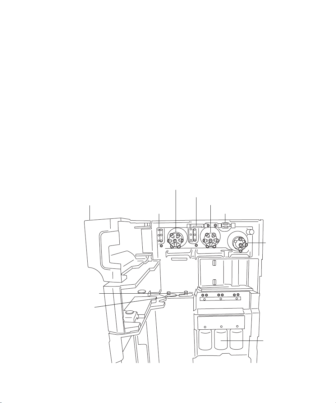
The IntelliStart Fluidics system comprises the components shown in the
following figure.
System components and configuration
(Tubing connections omitted for clarity)
Access doors
Tubing guides
Lock-spray selector valve
Flow sensor
Sample selector valve
Grounded union
Lock-spray pump
Sample pump
1-10 System Overview
A
B
C
A
B
C
C
B
A
Waters
A
C
B
Diverter valve
Sample vials
(A, B, and C)
Page 29

The IntelliStart Fluidics system consists of these components:
• A sample delivery system, with a rate pump, sample selector valve and
diverter valve used for LC and probe connections.
• A lock-spray system, with a pump capable of ultra-low flow rates, a
lock-spray selector valve, flow sensor, and grounded union. The
grounded union protects the flow sensor from probe voltages. The flow
sensor regulates flow rate, reducing it to accommodate the very low
volumes required by the NanoLockSpray source.
• Three, shared, 30-mL sample vials; A, B, and C.
• Plumbing for shared wash and waste bottles.
Sample vials A, B, and C are mounted on the instrument’s front panel. When
you select a solvent in the Instrument Console software, its vial is
illuminated. You can simultaneously illuminate all three vials, or extinguish
the illumination when you are using light-sensitive samples. Generally, vial A
contains the sample solution, vial B the reference solution, and vial C the
calibrant solution.
The wash reservoir and (optionally) the reservoir containing reference
solution are external to the instrument; typically, they are bottles placed on
top of the LC system. The waste reservoir is normally a bottle stored under
the instrument bench.
During normal operation, the IntelliStart Fluidics system’s access doors must
be closed.
System operation
You use the console software to configure the IntelliStart Fluidics system. You
can edit the parameters, frequency, and extent of the automation. See the
mass spectrometer’s online Help for further details on IntelliStart software
and operating the IntelliStart Fluidics system.
During auto-calibration, the software automatically controls reference
solution and sample delivery.
IntelliStart Fluidics system 1-11
Page 30

Ion optics
The mass spectrometer’s ion optics operate as follows:
1. Samples from the LC or instrument’s solvent delivery system are
introduced at atmospheric pressure into the ionization source.
2. The ions pass through the sample cone, into the vacuum system.
3. The ions pass through the T-Wave™ ion guide to the quadrupole, where
they are filtered according to their mass-to-charge ratio.
4. The mass-separated ions pass into the Triwave™ region, where they can
undergo collision-induced dissociation (CID).
5. The ions then pass into the time-of-flight (TOF) analyzer. A high-voltage
pulse orthogonally accelerates the ions down the flight tube, where the
dual-stage reflectron reflects them towards the ion mirror, which, in
turn, reflects the ions back to the dual-stage reflectron. The dual-stage
reflectron then reflects the ions to the detector. Ions of different
mass-to-charge ratios arrive at the detector at different times, hence a
mass spectrum can be created.
6. The signal from the detector is amplified, digitized, and sent to the
MassLynx software.
1-12 System Overview
Page 31

Ion optics overview
LockSpray sprayer
Sample spray
Oil-free scroll pump
Source T-Wave ion guide
Quadrupole
Air-cooled turbomolecular pumps
Dual-stage reflectron
Transfer lenses
Triwave
Pusher
Detector
QuanTof™
Ion
mirror
Analyzers
The system uses both quadrupole and time-of-flight (TOF) mass analyzers.
You can use the TRAP T-Wave and TRANSFER T-Wave regions of the
Triwave device for fragmentation analyses.
Quadrupole
The quadrupole is available with 4, 8, and 32 kDa mass range options, and
you can operate it in the following modes:
• Without applying the resolving dc voltage – A broad mass-to-charge
range of ions passes through, and the TOF analyzer accurately
measures their mass (MS acquisition).
• Applying the resolving dc voltage and selecting a specific mass.
• With the instrument automatically switching between MS and MS/MS
modes – known as Data Directed Analysis (DDA™), this operation
depends on the ions detected in an MS scan.
Analyzers 1-13
Page 32
Triwave technology
Triwave technology incorporates three T-Wave devices, each performing a
distinct function:
• The first T-Wave ion guide (Trap) transfers ions to the second T-Wave
ion guide and can function as a collision cell.
• The second T-Wave ion guide transfers ions to the third T-Wave ion
guide.
• The third T-Wave ion guide (Transfer) can function as a collision cell
and transfers ions to the oa-TOF for mass analysis.
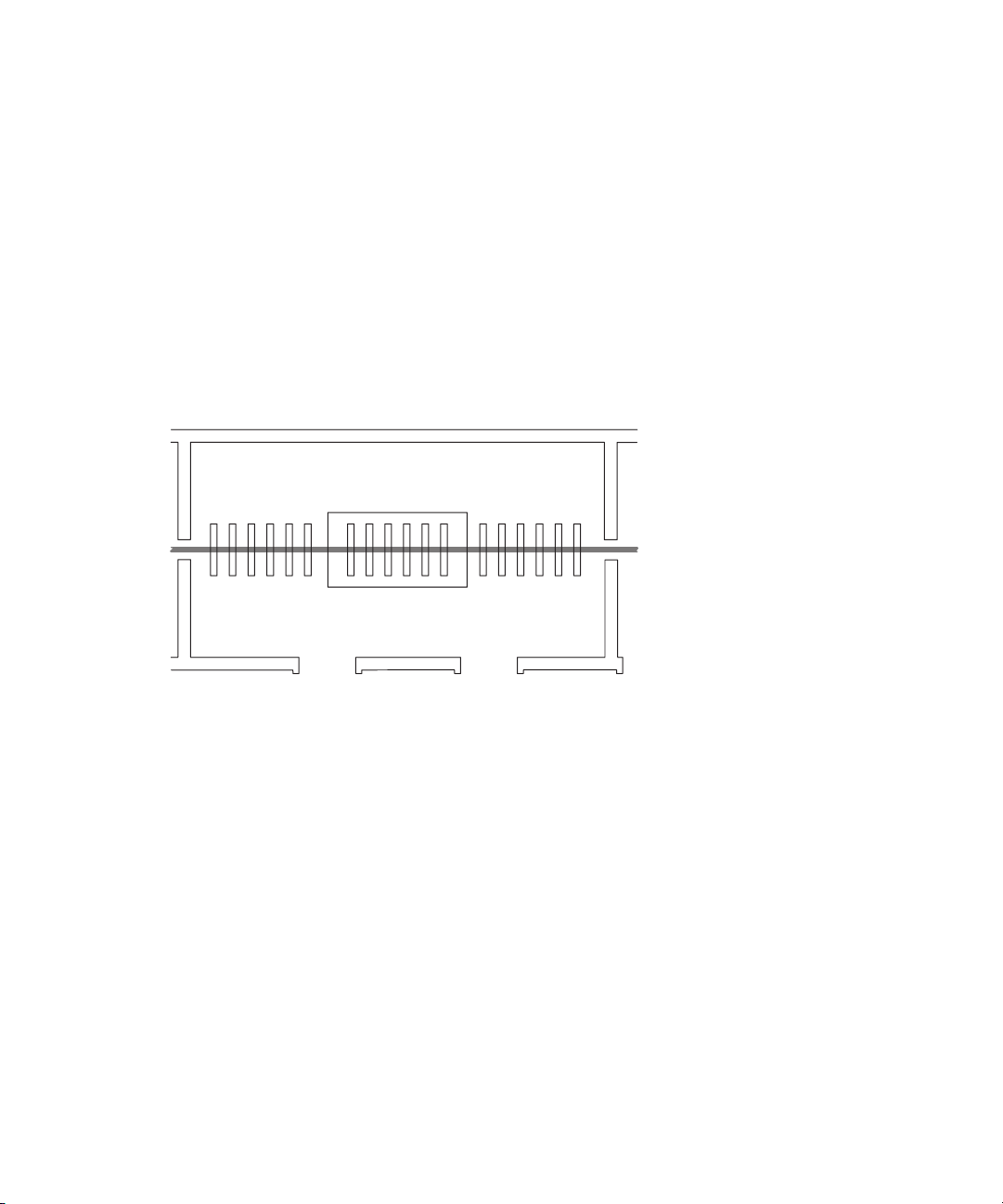
Triwave technology
Trap
T-Wave
Transfer
T-Wave
See the mass spectrometer’s online Help for details.
1-14 System Overview
Page 33

TOF analyzer
The orthogonal acceleration, dual reflectron geometry of the TOF analyzer
provides high resolution and exact mass capabilities. You can operate the
analyzer in the modes described in this table.
TOF analyzer operating modes
Resolving mode Description
Sensitivity Maximum sensitivity using single-pass TOF. In this
Resolution Highest resolution using single-pass TOF.
High-Resolution This double-pass TOF mode offers higher resolution
mode, the ions travel from the high-field pusher to the
dual-stage reflectron and then to the detector (see the
figure on page 1-16).
than the single-pass Resolution mode. Ions travel
between the analyzer components in the following
sequence:
• From the high-field pusher to the dual-stage
reflectron.
• From the dual-stage reflectron to the ion mirror.
• From the ion mirror back to the dual-stage
reflectron.
• From the dual-stage reflectron to the detector.
See the figure on page 1-16.
Analyzers 1-15
Page 34
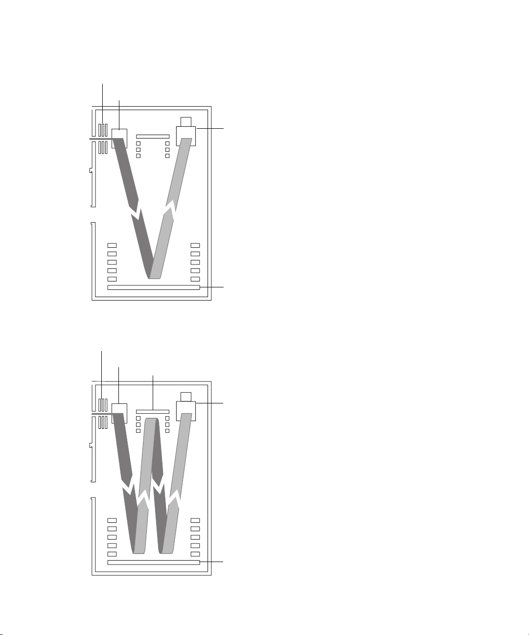
Single-pass mode
Transfer lens
High-field pusher
Double-pass mode
Detector
Dual-stage reflectron
Transfer lens
High-field pusher
Ion mirror
1-16 System Overview
Detector
Dual-stage reflectron
Page 35

Mass spectrometer configuration
The mass spectrometer consists of four principle components: the source, a
quadrupole, a Triwave device, and a TOF mass analyzer. Ionized sample
produced in the source travels through the quadrupole and Triwave. The TOF
detector system records mass spectra as its output.
Using MassLynx and the instrument control software, you control, configure,
and operate the instrument.
The following processes are performed using the MassLynx software:
• Configuring the SYNAPT G2 MS system
• Calibrating the SYNAPT G2 MS system
• Creating inlet and experiment methods that define operating
parameters for an analysis run
• Running samples
• Monitoring acquisition status
• Acquiring data
• Processing data
• Viewing the data
See also: The MassLynx User’s Guide. Also, the MassLynx online Help
provides more information on installing and using the MassLynx software.
Triwave device
The Triwave device consists of three T-Wave ion guides and is automatically
configured. The device transfers ions from the quadrupole to the TOF with
optimum efficiency, and it provides two separate collision cell regions (TRAP
and TRANSFER T-Waves) for optimized fragmentation of compounds of
interest. The collision energy, and hence the degree of fragmentation, is
manually or automatically controllable.
TOF
With its associated detector, the TOF records mass spectra derived from the
ions’ time of flight. A high voltage pulse orthogonally accelerates the ions by
pushing them out across their direction of travel, into a flight tube. A
reflectron reflects the ions back toward the detector.
Mass spectrometer configuration 1-17
Page 36

Ions of different mass-to-charge ratios evidence different flight times. So when
the detector records the time an ion arrives, that time is converted to mass
and plotted against abundance to create a mass spectrum.
Users can define recorded mass-to-charge ratios up to 100,000 Da in
single-pass mode, or 32,000 Da in double-pass mode.
Leak sensors
Leak sensors in the drip trays of the SYNAPT G2 MS continuously monitor
the instrument’s IntelliStart Fluidics system for liquid leaks. A leak sensor
stops system flow when it about 1.5 mL of accumulated leaked liquid in its
surrounding reservoir. At the same time, the Instrument Console software
displays an error message alerting you that a leak has developed.
See also: Waters ACQUITY UPLC Leak Sensor maintenance instructions
(part number 71500082506).
Vacuum system
The vacuum system consists of a scroll pump and six turbomolecular pumps
that pump down (evacuate) these regions of the system:
• Source T-Wave ion guide
• Quadrupole
• Triwave device
• Transfer lenses
• Time-of-flight (TOF) analyser
The oil-free scroll pump backs the turbo pumps and rough pumps the first
vacuum stage.
Protective interlocks guard against vacuum leaks and electrical or vacuum
pump failure. The system monitors the turbomolecular pump speeds and
continuously measures vacuum pressure with built-in gauges. The gauges
also serve as switches, stopping operation when vacuum loss is sensed.
A vacuum isolation valve isolates the sample cone from the mass analyzer,
allowing the sample cone to be cleaned without venting the instrument.
1-18 System Overview
Page 37
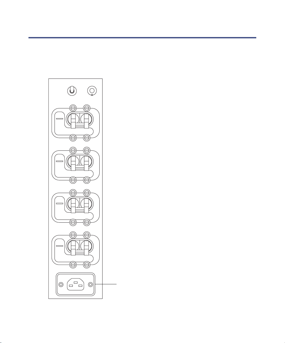
Controls on the instrument’s rear panel
The main power switches are on the instrument’s rear panel, (see the figure
on page B-2).
Main power switches
AUTO
PUMP
OVERRIDE
ON
OFF
AUXILIARY
ON
OFF
ON
OFF
VACUUM
EPC
RESET
EPC
ON
OFF
ELECTRONICS
200-240V, 50/60Hz, 2kW
Power connection
Controls on the instrument’s rear panel 1-19
Page 38

Main power switches
Switch Description
Pump override Used during servicing, this control must remain in
the Auto position at all other times.
EPC reset Used to reboot the embedded PC (EPC).
Requirement: The electronics and EPC switches
must be switched on.
Auxiliary This switch provides for future needs by operating a
spare power source.
EPC This switch controls the power supply to the
embedded PC.
Vacuum This switch controls the power supply to the vacuum
pumps and system vents.
Electronics This switch controls the power supply to the main
control electronics, embedded PC, and auxiliary
components.
1-20 System Overview
Page 39

2 Starting Up and Shutting Down
the Mass Spectrometer
This chapter describes how to start up, shut down, and reboot the mass
spectrometer.
Contents
Topic Page
Starting the mass spectrometer 2-2
Preparing the IntelliStart Fluidics system 2-4
Shutting down the mass spectrometer 2-6
Rebooting the embedded PC 2-7
2-1
Page 40

Starting the mass spectrometer
The Waters SYNAPT G2 MS is compatible with the ACQUITY UPLC and
nanoACQUITY UPLC systems. If you are not using either of these systems,
refer to the documentation relevant to your LC system.
Caution: Using incompatible solvents can severely damage the
instrument. For more details, refer to the following sources:
• Appendix C, “Materials of construction and compliant solvents”, for
mass spectrometer solvent information.
• Appendix C of the ACQUITY UPLC System Operator’s Guide (part
number 71500082502), for solvent compatibility with ACQUITY
UPLC devices.
Starting the mass spectrometer entails powering-on the MassLynx
workstation, logging in to the workstation, powering-on the mass
spectrometer and all other ACQUITY UPLC instruments, and starting the
MassLynx software.
Requirement: You must power-on and log in to the MassLynx workstation
first to ensure that it obtains the IP addresses of the system instruments.
See the mass spectrometer’s online Help for details on MassLynx and
IntelliStart applications.
To start the mass spectrometer
Warning: To avoid ignition of flammable solvents, never let the nitrogen
supply pressure fall below 400 kPa (4 bar, 58 psi).
1. Ensure that all the mass spectrometer’s external connections are in
place (see Appendix B, “External Connections”).
2. Power-on the MassLynx PC, and log in before powering-on the other
instruments.
3. On the instrument’s rear panel, ensure that the pump override switch is
in the auto position, and the EPC, vacuum, and electronics main power
switches are switched on (see page 1-19).
Result: Each system component runs a series of startup tests.
4. Allow 4 minutes for the embedded PC to initialize.
2-2 Starting Up and Shutting Down the Mass Spectrometer
Page 41

5. Start the MassLynx software.
Tip: You can monitor the Instrument Console for messages and LED
indications.
6. Click IntelliStart, in the MassLynx main window’s lower, left-hand
corner.
Result: The mass spectrometer’s console appears. The mass
spectrometer is in Standby mode.
7. Click Operate .
Result: When the mass spectrometer is ready to operate, IntelliStart
software displays “Ready” in the Instrument Console.
Calibration information
You must calibrate the mass spectrometer prior to use. You can perform this
task using IntelliStart software.
See also: The mass spectrometer’s online Help.
Flow rates for the ACQUITY UPLC SYNAPT G2 MS UPLC/MS/MS
system
The ACQUITY UPLC system can run at high flow rates. To optimize
desolvation, and thus sensitivity, run the ACQUITY UPLC SYNAPT G2 MS
UPLC/MS/MS system at appropriate gas flows and desolvation temperatures.
Flow rate versus temperature and gas flow
Flow rate
(mL/min)
0.000 to 0.020 100 200 800
0.020 to 0.100 120 350 800
0.101 to 0.300 120 450 800
0.301 to 0.500 150 500 1000
>0.500 150 600 1200
Source
temperature (°C)
Desolvation
temperature (°C)
Starting the mass spectrometer 2-3
Desolvation gas
flow (L/h)
Page 42

Preparing the IntelliStart Fluidics system
For additional information, see “Connecting the liquid waste line” on
page B-13.
Installing the vials
Use standard vials (30 mL) for instrument setup and calibration. To infuse
relatively small volumes, use the Low-volume Adaptor Kit (included). The
volume of the low-volume vials is 1.5 mL.
Required materials
Chemical-resistant, powder-free gloves
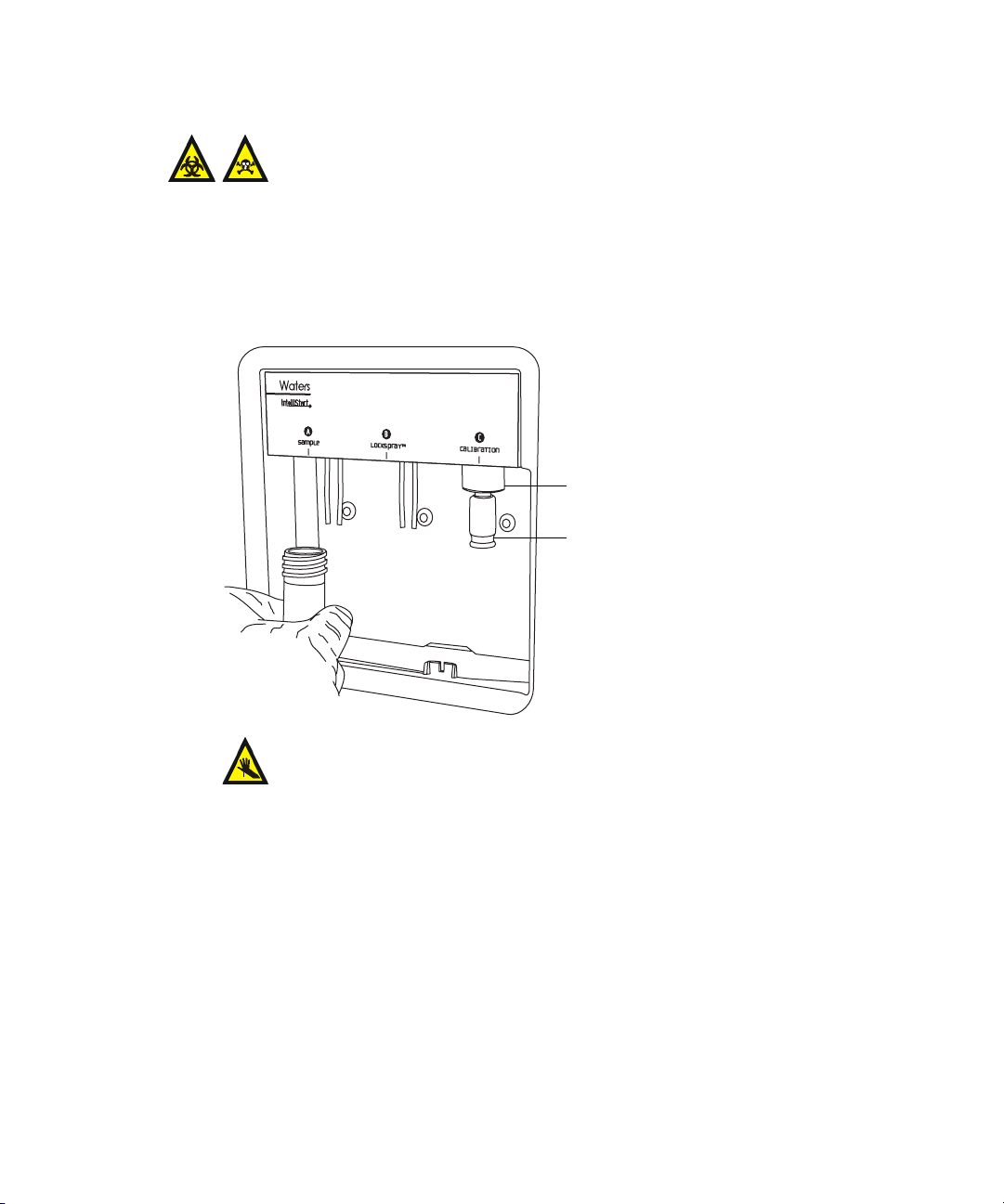
To install the vials
Warning: The vials can be contaminated with biohazardous and/or
toxic materials. Always wear chemical-resistant, powder-free
gloves while performing this procedure.
1. Remove the vial caps.
2. Screw the vials onto the mass spectrometer, as shown below.
Vial
2-4 Starting Up and Shutting Down the Mass Spectrometer
Page 43
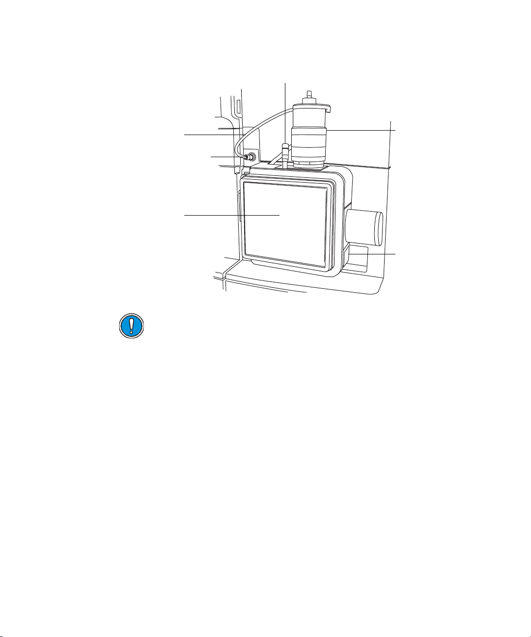
To install the low-volume vials
Warning: The vials can be contaminated with biohazardous and/or
toxic materials. Always wear chemical-resistant, powder-free
gloves while performing this procedure.
1. If a standard vial is fitted, remove it.
2. Screw the low-volume adaptors into the manifold and finger-tighten
them.
Low-volume adaptor
Low-volume vial
Warning: Low-volume glass vials are fragile and can shatter,
cutting fingers. Take care and never use force when screwing
them into the adaptors.
3. Screw the low-volume vials into the adaptors.
Purging the pump
Whenever you replace a solution bottle, purge the pump with the solution that
you are going to use next. See the mass spectrometer’s online Help for details.
Tip: Depending on the solutions used, the system can require more than one
purge cycle to minimize carryover.
Preparing the IntelliStart Fluidics system 2-5
Page 44

Shutting down the mass spectrometer
You can shut down the system by putting it in Standby mode, by fully
shutting it down, or by rebooting it.
Putting the mass spectrometer in Standby mode
Leave the mass spectrometer in Operate mode except in the following cases,
when you must put it in the Standby mode:
• When performing routine maintenance
• When changing the source
• When leaving the mass spectrometer unused for a long period
To put the system in Standby mode
In the Tune window, click to put the mass spectrometer in
Standby mode.
Result: Doing so turns off the source voltages, gas flows, Intellistart
Fluidics system, and LC system.
Fully shutting down the mass spectrometer
To fully shut down the mass spectrometer
1. In the Tune window, click .
2. Click Vacuum > Vent.
3. Select Vent Instrument.
Result: A message confirms the vent command.
4. Click OK.
Result: When the turbomolecular pumps slow to half their normal
operating speed, the vent valves open, and the instrument automatically
vents.
5. Exit the MassLynx software.
6. Shut down the PC.
2-6 Starting Up and Shutting Down the Mass Spectrometer
Page 45

7. Switch off all the peripherals.
8. Switch off the vacuum, electronics, and the embedded PC and auxiliary
breakers located on the rear panel.
Rebooting the embedded PC
Reboot the embedded PC when either of these conditions applies:
• The MassLynx software fails to initialize.
• Immediately following a software upgrade.
To reboot the embedded PC
Caution: When rebooting, do not switch off power to the instrument, as
this will vent the instrument.
1. In the MassLynx software, close the Tune window.
2. On the instrument’s rear panel, switch off the EPC power switch, wait
5 seconds, and switch it back on.
3. Wait 4 minutes to allow full rebooting to take place.
4. Open the MassLynx software.
Rebooting the embedded PC 2-7
Page 46

2-8 Starting Up and Shutting Down the Mass Spectrometer
Page 47

3 Configuring the LockSpray
Source
This chapter explains how to configure the Electrospray source for the
following ionization modes:
•ESI
•APCI
•ESCi
Contents
Topic Page
Configuring the LockSpray source 3-2 Configuring for ESI mode 3-2 Installing the ESI small bore capillary option 3-8 Configuring for APCI mode 3-14 Configuring for ESCi mode 3-19
3-1
Page 48
Configuring the LockSpray source
The following table summarizes how you configure the LockSpray source for
the various ionization modes.
Configuring the LockSpray source
Ionization mode Probe type Corona pin fitted?
ESI ESI No
APCI APCI Yes
ESCi ESI Yes
Configuring for ESI mode
To operate in ESI mode, you must fit the ESI probe to the LockSpray source
enclosure. If you intend using the small-bore capillary option, fit the capillary
to the probe first (see page 3-8).
For more information on using ESI mode, see the SYNAPT G2 MS system
online Help.
Installing the ESI probe
Required materials
• Chemical-resistant, powder-free gloves
• PEEK™ tubing
To install the ESI probe
Warning: The LC system connections, ESI probe, and source can
be contaminated with biohazardous and/or toxic materials. Always
wear chemical-resistant, powder-free gloves while performing this
procedure.
Warning: To avoid electric shock, ensure that the instrument is
prepared for working on the source before commencing this procedure.
3-2 Configuring the LockSpray Source
Page 49

1. Prepare the instrument for working on the source (see page 5-7).
Warning: The ESI probe tip is sharp. To avoid puncture wounds,
handle the ESI probe with care.
2. Remove the protective sleeve, if fitted, from the ESI probe tip.
3. Carefully slide the ESI probe into the hole in the probe adjuster
assembly, ensuring that the probe location dowel aligns with the
location hole in the probe adjuster assembly.
ESI probe location dowel
TP03129
Location hole in the probe
adjuster assembly
Configuring for ESI mode 3-3
Page 50
ESI probe, mounted on the LockSpray source enclosure
Vernier probe adjuster
ESI probe
ESI probe cable
High voltage connector
Source window
TP03128
Probe locking ring
Source enclosure
release
Caution: To avoid nitrogen leakage, fully tighten the probe locking
ring.
4. Tighten the probe locking ring to secure the probe in place.
5. Connect the ESI probe’s cable to the high voltage connector.
6. Slide open the instrument’s source interface door.
3-4 Configuring the LockSpray Source
Page 51

Source interface door
Source interface door.
Warning: To avoid electric shock, do not use stainless steel tubing
to connect the diverter valve to the ESI probe; use the PEEK
tubing supplied with the instrument.
7. Using PEEK tubing greater than or equal to 0.004-inch ID, connect
port 2 (the top port) of the diverter valve to the ESI probe.
Recommendation: To reduce peak broadening, use 0.004-inch ID tubing
for sample flow rates ≤1.2 mL/min; use 0.005-inch ID tubing for sample
flow rates >1.2 mL/min.
Requirement: When replacing tubing supplied with the instrument,
minimize the length connecting the diverter valve to the ESI probe.
Doing so minimizes delays and dispersion.
Configuring for ESI mode 3-5
Page 52
• At the diverter valve, use a long "finger tight" PEEK fitting.
• At the probe, use a PEEK nut and ferrule, finger tightened, to
connect to the PEEK union.
Tubing connection between the diverter valve and the ESI probe
(The other connections are omitted for clarity.)
Long "finger tight" PEEK fitting
Diverter valve
Tubing connection
Caution: Ensure that the tubing does not become trapped when
closing the source interface door.
8. Slide closed the instrument’s source interface door.
3-6 Configuring the LockSpray Source
PEEK nut and ferrule
ESI probe
Probe adjuster
assembly
Page 53
Removing the ESI probe
Required materials
Chemical-resistant, powder-free gloves
To remove the ESI probe
Warning: The LC system connections, ESI probe, and source can
be contaminated with biohazardous and/or toxic materials. Always
wear chemical-resistant, powder-free gloves while performing this
procedure.
Warning: To avoid electric shock, prepare the instrument for work
performed on its source before commencing this procedure.
1. Prepare the instrument for work performed on its source (see page 5-7).
2. Disconnect the fluidics tubing from the ESI probe.
3. Disconnect the ESI probe’s cable from the high voltage connector.
4. Unscrew the probe locking ring.
Warning: The ESI probe tip is sharp. To avoid puncture wounds,
handle the probe with care.
5. Carefully remove the ESI probe from the probe adjuster assembly.
6. If available, fit the protective sleeve to the ESI probe tip.
Configuring for ESI mode 3-7
Page 54

Installing the ESI small bore capillary option
The ESI small bore capillary option is for use with 1-mm UPLC columns
running at flowrates of 100 to 200 µL/min. The materials needed for this task
are in the Small-Bore Capillary kit.
Caution: To avoid damage from excessive pressure, do not exceed flow
rates of 200 µL/min through the ESI probe when using the small-bore
capillary.
Required materials
• Chemical-resistant, powder-free gloves
• Combined 2.5-mm Allen wrench and cone extraction tool
•10-mm wrench
•8-mm wrench
• 2 × 7-mm wrenches
•LC pump
• HPLC-grade (or better) 1:1 acetonitrile:water
• Sharp knife or PEEK tubing cutter
• From the Small-Bore Capillary kit:
– Capillary
– Small-bore, UNF coupler (slide port)
– Collar nut (thumb nut)
– PTFE liner tube
– Conductive sleeve
– 2 × 1/16-inch ferrules
• Metal gasket for the probe tip
• Safety goggles
3-8 Configuring the LockSpray Source
Page 55
To install the capillary
Warning: The probe and source components can be contaminated
with biohazardous and/or toxic materials. Always wear
chemical-resistant, powder-free gloves while performing this
procedure.
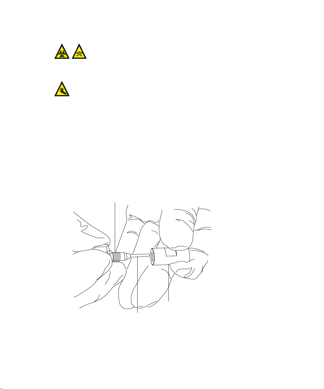
Warning: The ESI probe tip is sharp. To avoid puncture wounds, handle
the probe with care.
1. Remove the existing capillary (see page 5-59).
2. Using the sharp knife or PEEK tubing cutter, cut an approximately
60-cm (24-inches) length of red PEEK tubing.
Requirement: To minimize dead volume, cut the ends of the tubing
squarely (that is, perpendicular to the tube’s horizontal axis).
3. Insert one end of the red PEEK tubing in the probe inlet connector, and
finger tighten the connector in the PEEK union.
Rationale: Doing so ensures a minimum dead volume when fitting the
capillary.
Probe inlet connector
PEEK tubing
Installing the ESI small bore capillary option 3-9
PEEK union
TP02671
Page 56
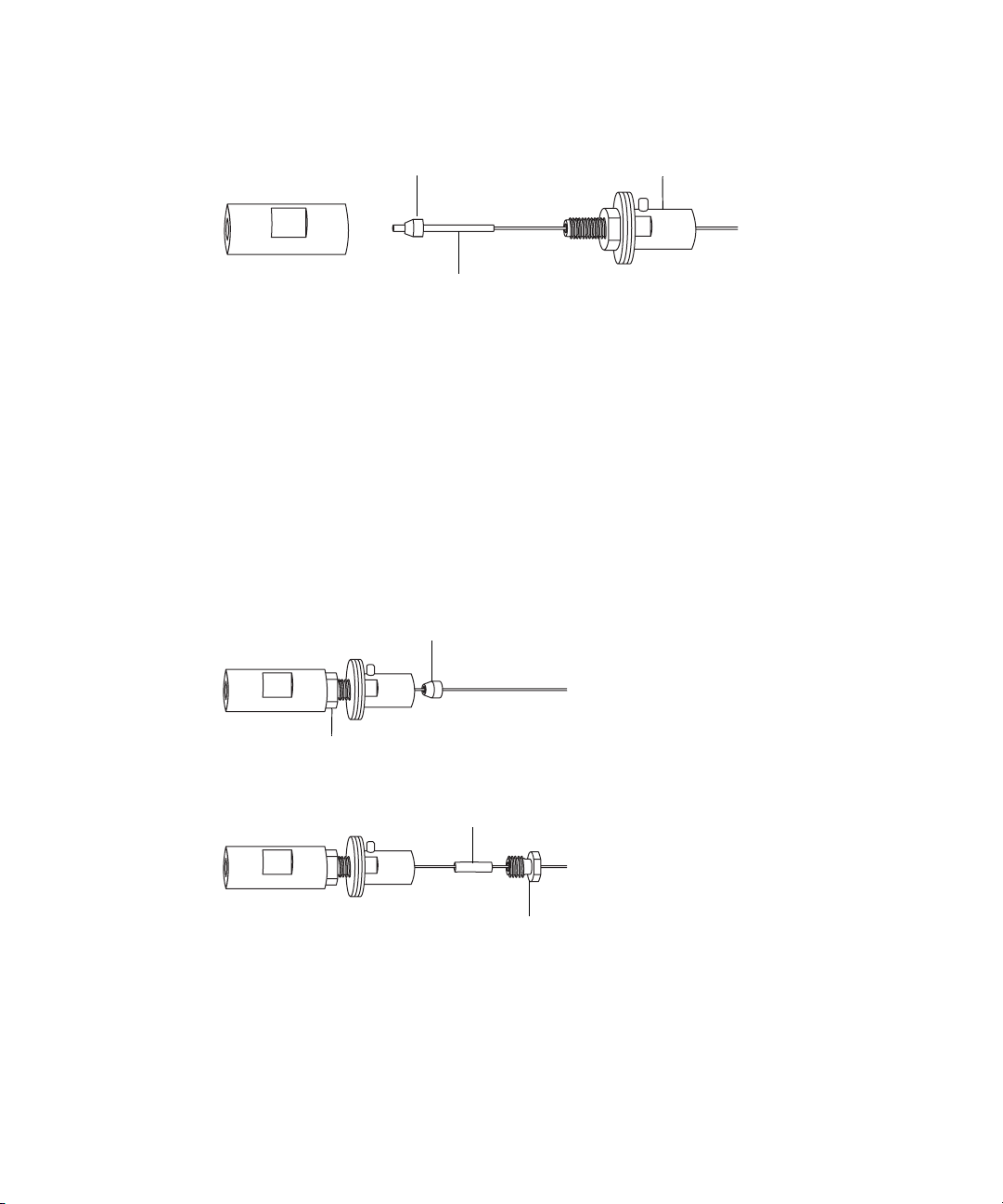
4. Using the needle-nose pliers, slide the UNF coupler, PTFE liner sleeve,
and a ferrule onto the capillary.
Ferrule
PTFE liner sleeve
UNF coupler
5. Insert the capillary in the PEEK union, and ensure that it is fully
seated.
6. Finger-tighten the UNF coupling into the PEEK union.
7. Gently tug on the capillary, testing to ensure that it stays in place.
8. Using the 7-mm wrench for the locknut and the 8-mm wrench for the
PEEK union, tighten the locknut against the PEEK union until the
union can no longer be twisted.
9. Using the needle-nose pliers, slide another 1/16-inch ferrule over the
capillary and seat it in the UNF coupler over the exposed end of the
PTFE liner sleeve.
Ferrule
Locknut
10. Slide a new conductive sleeve and the collar nut over the capillary.
11. Using two 7-mm wrenches, tighten the collar nut to the UNF coupling.
3-10 Configuring the LockSpray Source
Conductive sleeve
Collar nut
Page 57
Warning: To avoid high-pressure jet spray, wear safety goggles
when performing the leak test.
12. Perform a leak test by attaching the free end of the PEEK tubing to an
LC pump and pumping mobile phase through it, at 200 µL/min.
• If leakage occurs, disassemble and remake the connection, and
repeat the leak test.
• If the backpressure on the LC pump is high, replace the capillary,
and repeat the leak test.
13. When no leakage occurs and the backpressure on the LC pump is
normal, disconnect the PEEK tubing from the LC pump.
14. Remove the probe inlet connector and red PEEK tubing from the PEEK
union.
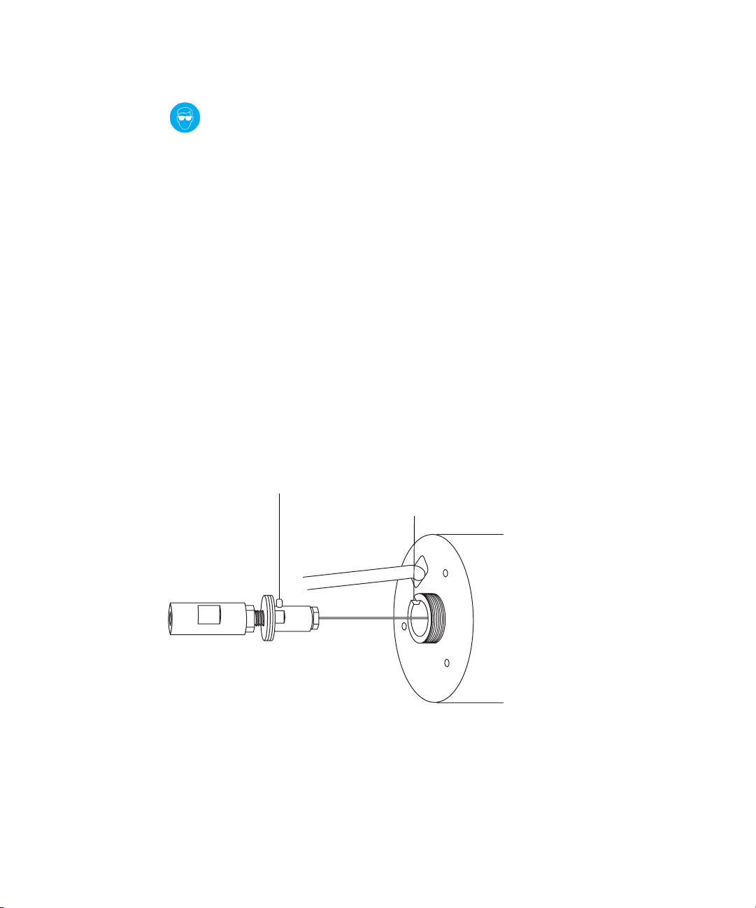
15. Carefully thread the capillary through the probe assembly.
16. Carefully push the PEEK union/UNF coupling assembly and capillary
into the probe assembly so that the locating pin on the UNF coupling is
fully engaged in the locating slot at the head of the probe assembly.
UNF coupling locating pin
Probe assembly locating slot
17. Fit the nebulizer adjuster knob to the PEEK union/UNF coupling
assembly.
18. Finger-tighten the nebulizer adjuster knob onto the probe assembly.
Installing the ESI small bore capillary option 3-11
Page 58

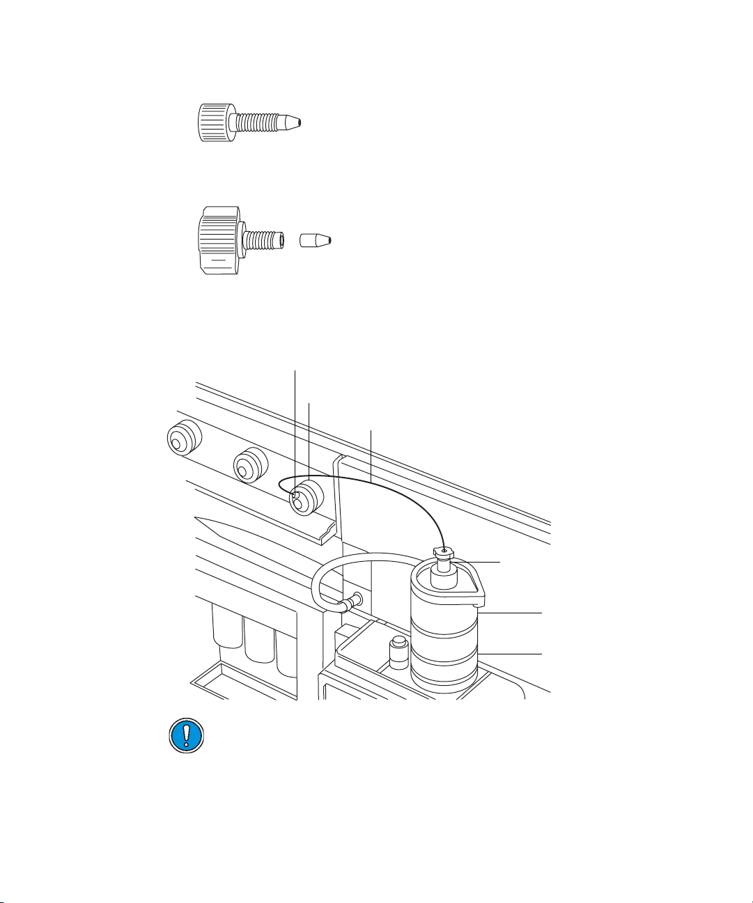
19. Fit the new metal gasket to the probe tip.
Metal gasket
20. Fit the probe tip over the capillary, and screw the tip onto the probe
assembly.
Caution: To avoid gas leakage, fully tighten the probe tip.
21. Using the 10-mm wrench, tighten the probe tip.
10-mm wrench
22. Using the nebulizer adjuster knob, adjust the capillary so that it
protrudes by approximately 0.5 mm from the end of the probe tip.
Tip: During normal operation, the adjuster knob relies on gas pressure
to retract the capillary. To retract the capillary in the absence of gas
pressure, invert the probe, and use gravity.
3-12 Configuring the LockSpray Source
Probe tip
Page 59

23. Fit the end cover and gasket to the probe assembly.
Nebulizer adjuster knob
Gasket
End cover
24. Using the combined 2.5-mm Allen wrench, fit and tighten the 3 screws
that retain the end cover.
End-cover retaining screws
Installing the ESI small bore capillary option 3-13
Page 60

25. Replace the combined 2.5-mm Allen wrench and cone extraction tool in
its storage location on the source adaptor housing.
26. Fit the ESI probe to the source (see page 3-2).
Configuring for APCI mode
To operate in APCI mode, you must fit the APCI probe and corona pin to the
LockSpray source enclosure.
For more information on using APCI mode, see the SYNAPT G2 MS system
online Help.
Installing the APCI probe
Required materials
• Chemical-resistant, powder-free gloves
• PEEK tubing
To install the APCI probe
Warning: The LC system connections, APCI probe, and source can
be contaminated with biohazardous and/or toxic materials. Always
wear chemical-resistant, powder-free gloves while performing this
procedure.
Warning: To avoid electric shock, prepare the instrument for work
performed on its source before commencing this procedure.
3-14 Configuring the LockSpray Source
Page 61

1. Prepare the instrument for work performed on its source (see page 5-7).
2. Carefully slide the APCI probe into the hole in the probe adjuster
assembly, ensuring that the probe location dowel aligns with the
location hole in the probe adjuster assembly.
APCI probe location dowel
Location hole in the probe
adjuster assembly
TP03129
Configuring for APCI mode 3-15
Page 62

3. Tighten the probe locking ring to secure the probe in place.
APCI probe mounted on the source enclosure
Vernier probe adjuster
APCI probe
Probe locking ring
Vertical probe
adjuster
Source window
Source enclosure
release
TP03128
4. Slide open the instrument’s source interface door (see the figure on
page 3-5).
Warning: To avoid electric shock, do not use stainless steel tubing
to connect the diverter valve to the APCI probe; use the PEEK™
tubing supplied with the instrument.
5. Using tubing greater than or equal to 0.004-inch ID, connect port 2 (the
top port) of the diverter valve to the APCI probe.
Recommendation: To reduce peak broadening, use 0.004-inch ID tubing
for sample flow rates ≤1.2 mL/min; use 0.005-inch ID tubing for sample
flow rates >1.2 mL/min.
Requirement: If you are replacing the tubing supplied with the
instrument, minimize the length of the tubing connecting the diverter
valve to the APCI probe. Doing so minimizes delays and dispersion.
3-16 Configuring the LockSpray Source
Page 63

• At the diverter valve, use a long "finger tight" PEEK fitting.
• At the probe, use a PEEK nut and ferrule, finger tightened, to
connect to the PEEK union.
Tubing connection between the diverter valve and the APCI probe
(The other tubing connections are omitted for clarity.)
Long "finger tight" PEEK fitting
Diverter valve
Tubing connection
PEEK nut and ferrule
Caution: Ensure that the tubing does not become trapped when
closing the source interface door.
6. Slide closed the instrument’s source interface door.
Configuring for APCI mode 3-17
APCI probe
Probe adjuster
assembly
Page 64
Installing the corona pin in the source
Install the corona pin according to the procedure on page 5-12.
Removing the corona pin from the source
Remove the corona pin according to the procedure on page 5-14.
Removing the APCI probe
Required materials
Chemical-resistant, powder-free gloves
To remove the APCI probe
Warning: The LC system connections, APCI probe, and source can
be contaminated with biohazardous and/or toxic materials. Always
wear chemical-resistant, powder-free gloves while performing this
procedure.
Warning: To avoid electric shock, prepare the instrument for work
performed on its source before commencing this procedure.
1. Prepare the instrument for work performed on its source (see page 5-7).
2. Disconnect the diverter valve tubing from the APCI probe.
3. Unscrew the probe locking ring.
4. Carefully remove the probe from the probe adjuster assembly.
3-18 Configuring the LockSpray Source
Page 65

Configuring for ESCi mode
To operate in ESCi mode, you must fit the ESI probe and corona pin to the
LockSpray source enclosure.
The system, with the ESI probe installed and corona discharge pin fitted, can
alternate between ESI and ESCi modes, facilitating data acquisition in ESI
and ESCi modes in parallel. For more information on using dual ESI and
ESCi modes, see the SYNAPT G2 MS system online Help. When fitting the
ESI probe to the LockSpray source enclosure, follow the procedure on
page 3-2.
Optimizing the ESI probe for ESCi operation
See the mass spectrometer’s online Help for details on how to optimize the ESI
probe for ESCi operation.
Installing the corona pin in the source
Install the corona pin according to the procedure on page 5-12.
Removing the corona pin from the source
Remove the corona pin according to the procedure on page 5-14.
Configuring for ESCi mode 3-19
Page 66

3-20 Configuring the LockSpray Source
Page 67

4 Configuring the NanoLockSpray
source
The Waters NanoLockSpray™ dual, electrospray, ion source enables the
optimized co-introduction of sample and lock-mass reference compound
directly into the ion source. At low flow rates, this feature provides
authenticated, exact-mass measurement in both MS and MS/MS modes.
Contents
Topic Page
Overview of the NanoLockSpray source 4-2
Selecting and Configuring the NanoLockSpray source 4-4
Deploying the sprayer platform adjuster assembly 4-5
Adjusting the sprayer tip position 4-6
Setting up the camera 4-7
Optional glass capillary sprayer 4-8
4-1
Page 68
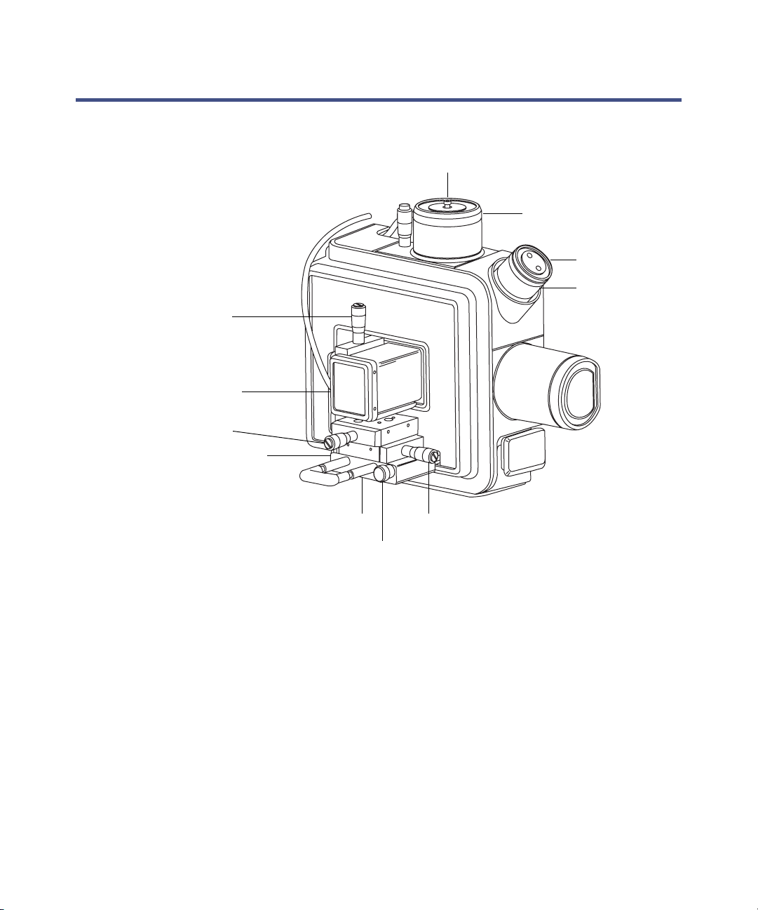
Overview of the NanoLockSpray source
NanoLockSpray source
LockSpray sprayer inlet
Z-position adjuster
Sprayer safety cover
X-position adjuster
Thumbscrew (on left-hand
side of sprayer platform)
NanoLockSpray reference
probe
Camera
Camera focussing
ring
Sprayer platform adjuster assembly
The NanoLockSpray source enclosure holds two nanospray sprayers
positioned orthogonally with respect to one another. The sample flows through
one sprayer and the lock-mass reference solution through the other. A
motorized baffle rotates to admit spray from either sprayer to the sampling
cone.
4-2 Configuring the NanoLockSpray source
TP03199
Y-position adjuster
Thumbscrew
Page 69
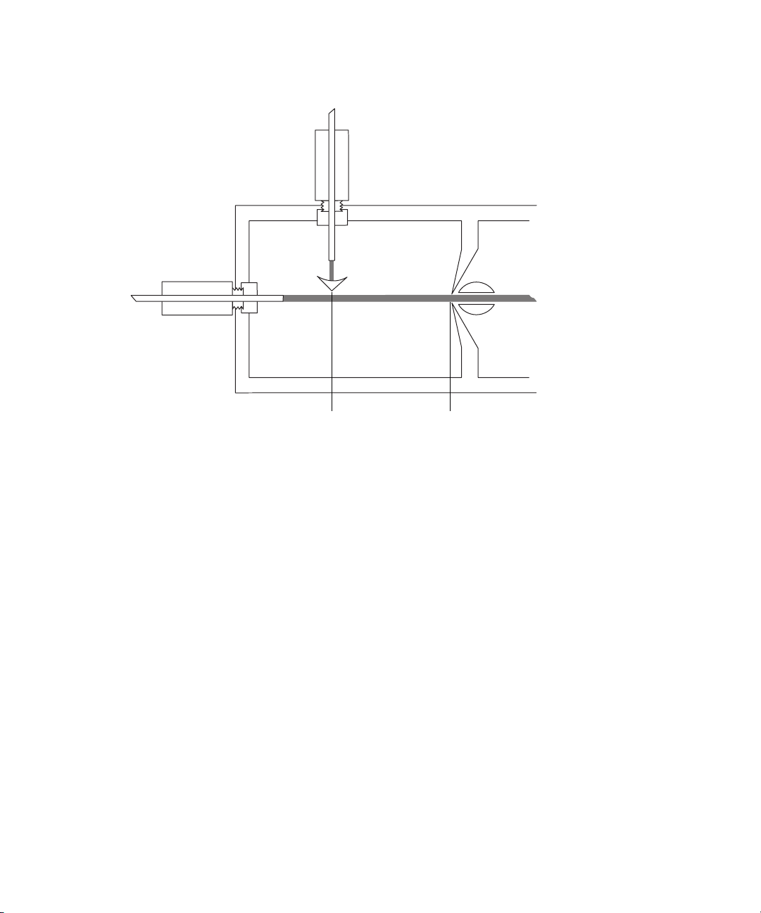
Schematic of the NanoLockSpray source
LockSpray sprayer
Sample sprayer
Spray indexing permits acquiring sample and lock-spray data in separate
data channels, and the baffle design ensures negligible cross-talk between the
two sprays. The lock-spray data are used to calculate a correction factor for
the mass-scale calibration, which is then applied to the sample data, providing
exact-mass information.
Sample sprayer
You can use the NanoLockSpray source with different NanoFlow sprayers.
For instructions on how to set up these sprayers, see page 4-4.
LockSpray sprayer
The LockSpray sprayers for the LockSpray source and NanoLockSpray source
operate as part of the instrument's IntelliStart Fluidics system. Fitted with a
500-µL pump, the LockSpray sprayer operates at 0.5 µL/min. You must choose
the concentration of the lock-spray reference solution that gives a suitable ion
intensity.
Baffle
Sample cone
Overview of the NanoLockSpray source 4-3
Page 70

NanoFlow gas supply
The sample sprayer nebulizer gas supply pressure is electronically controlled
from 0 to 2 bar. The optimum pressure is sprayer-dependent, but usually lies
between 0.3 and 1.0 bar.
Purge gas
Purge gas typically flows at 100 L/h. It provides a positive pressure in the
source enclosure that reduces the chemical background interference caused by
contaminants in the laboratory air. You can adjust this flow via the Tune
window’s Source tab, see the mass spectrometer’s online Help for further
details.
Sprayer platform adjuster assembly
The sprayer platform adjuster assembly allows precise X-, Y-, and
Z-positioning of the sprayer tip. You can also withdraw the sprayer from the
source to allow access to the sprayer tip.
Using the two thumbscrews on the base of the adjuster assembly, you can
move the platform in and out of the source (see “Deploying the sprayer
platform adjuster assembly” on page 4-5).
Selecting and Configuring the NanoLockSpray source
The Universal NanoFlow sprayer is installed as standard equipment on the
NanoLockSpray source. For installation and maintenance details, see the
Waters Universal NanoFlow Sprayer Installation and Maintenance Guide
(part number 71500110107).
To select the NanoLockSpray source, from the Tune window, click Source >
Nanoflow.
The following table summarizes how you configure the NanoLockSpray source
for the various ionization modes.
Tip: A corona pin is not used with the NanoLockSpray source.
4-4 Configuring the NanoLockSpray source
Page 71

NanoLockSpray source configuration
Sprayer type Used for
Universal NanoFlow nebulizer
sprayer
Borosilicate glass capillary
NanoFlow (see page 4-8).
NanoFlow capillary electrophoresis
(CE) sprayer. For details, see the
Capillary Electrophoresis/Capillary
Electrochromatography Sprayer
User's Guide (part number 6666522).
Flow injection or for coupling to
nanoACQUITY UPLC with regulated
flow rates down to 100 nL/min.
Extremely low flow rates (less than
100 nL/min).
Stable electrospray by means of a
make-up liquid at the CE capillary
tip. The make-up flow rate is less
than 1 µL/min.
Deploying the sprayer platform adjuster assembly
To move the sprayer platform out of the source
Warning: To avoid electrical shock, ensure the safety cover is in place
over the sprayer.
1. Confirm that the sprayer’s safety cover is installed (see the figure on
page 4-2).
2. Unscrew the thumbscrew on the front of the sprayer platform.
3. Pull out the side thumbscrew and withdraw the sprayer platform from
the source.
4. Release the side thumbscrew, locking the platform in the withdrawn
position.
Deploying the sprayer platform adjuster assembly 4-5
Page 72

To move the sprayer platform into the source
Warning: To avoid electrical shock, ensure the safety cover is in place
over the sprayer.
1. Confirm that the sprayer’s safety cover is installed (see the figure on
page 4-2).
2. Pull out the side thumbscrew, and push the sprayer platform into the
source.
3. Release the side thumbscrew, locking the platform in position.
4. Tighten the front thumbscrew, securing the adjuster assembly rigidly to
the source.
Adjusting the sprayer tip position
To adjust the tip position
1. Adjust the X, Y, and Z controls on the adjuster assembly to move the
sprayer tip close to the sampling cone and baffle.
2. Adjust the height of the sprayer so that its tip is level with the center of
the baffle.
3. Adjust the horizontal position of the sprayer so that the tip points
toward the left-hand side of the baffle.
Tips:
• If you observe an electrical discharge between the sprayer tip and
baffle, move the tip farther from the baffle, or reduce the capillary
voltage. Note, however, that the capillary voltage must be high
enough to maintain a good spray.
• Fine tune the position of the sprayer while acquiring a spectrum of a
standard compound. Small adjustments to the sprayer position can
make large differences to the source sensitivity.
4-6 Configuring the NanoLockSpray source
Page 73
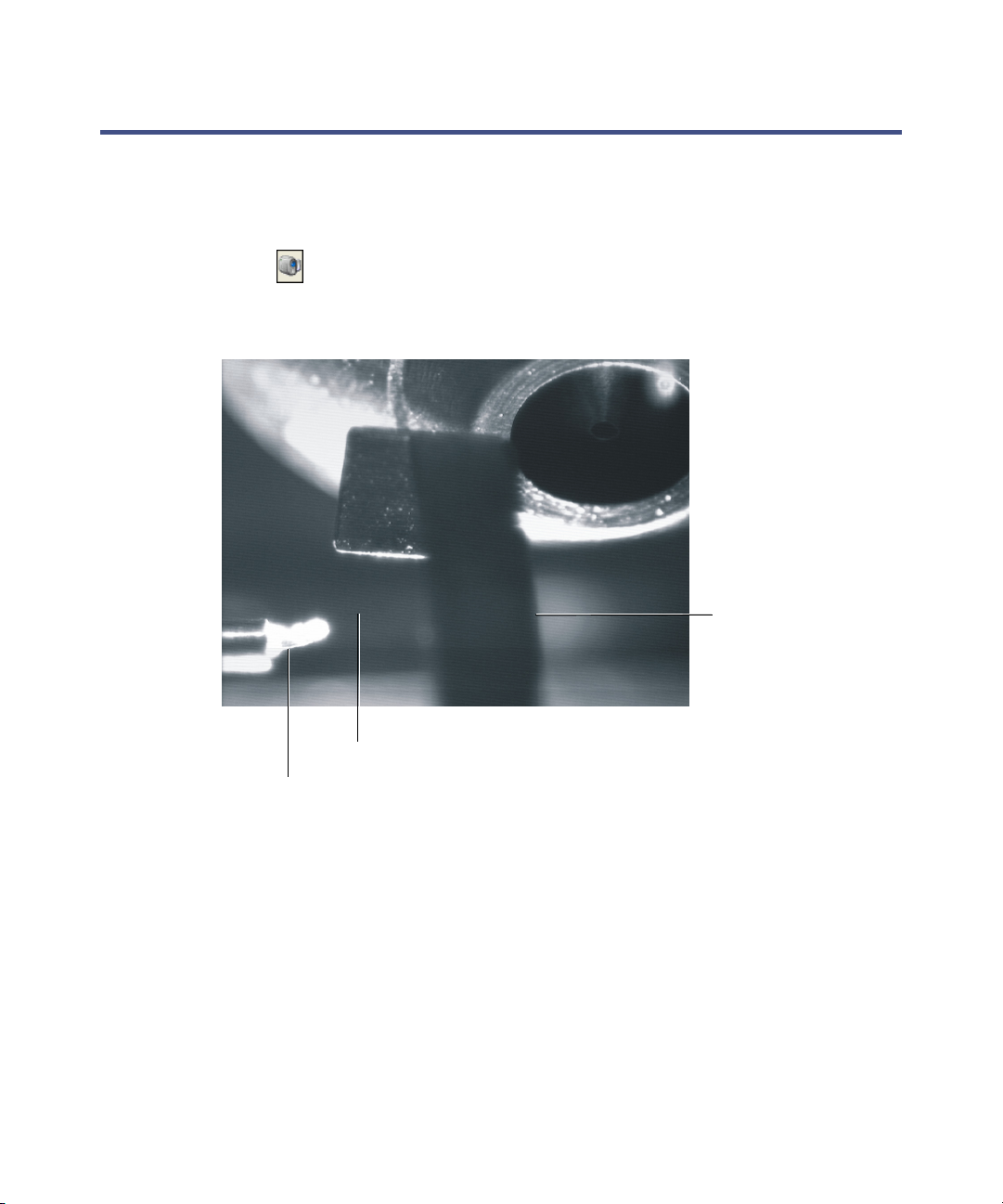
Setting up the camera
To set up the camera
1. On the Tune window click Source > Nanoflow.
2. Click to open the Camera Control dialog box.
Camera Control view of sprayers and sample cone
Sample cone
Baffle
Sample spray
Sample sprayer
3. Rotate the camera’s focusing ring to focus on the sample sprayer (see the
figure on page 4-2).
Setting up the camera 4-7
Page 74

Optional glass capillary sprayer
The glass capillary sprayer is designed for use with metal-coated borosilicate
glass capillaries, which allow extremely low flow rates (less than 100 nL/min).
The capillaries are used for one sample only and must then be discarded.
To use the glass capillary sprayer, you must complete the following
procedures:
• Install the glass capillary sprayer.
• Fit and load the glass capillary.
• Optimize the sprayer.
Installing the glass capillary sprayer
Required materials
Chemical-resistant, powder-free gloves
To install the glass capillary sprayer
Warning: The source components can be contaminated with
biohazardous and/or toxic materials. Always wear
f
chemical-resistant, powder-free gloves while performing this
procedure.
Warning: To avoid electric shock, prepare the instrument for work
performed on its source before commencing this procedure.
1. Prepare the instrument for work performed on its source (see page 5-7).
Warning: The probe and source can be hot. To avoid burn injuries,
take great care while working with these components.
2. In the Tune window, click Source Standby , and confirm that the
adjacent status display is yellow.
3. Retract the sprayer platform adjuster assembly from the source (see
page 4-5).
4. Remove the sprayer’s safety cover.
4-8 Configuring the NanoLockSpray source
Page 75
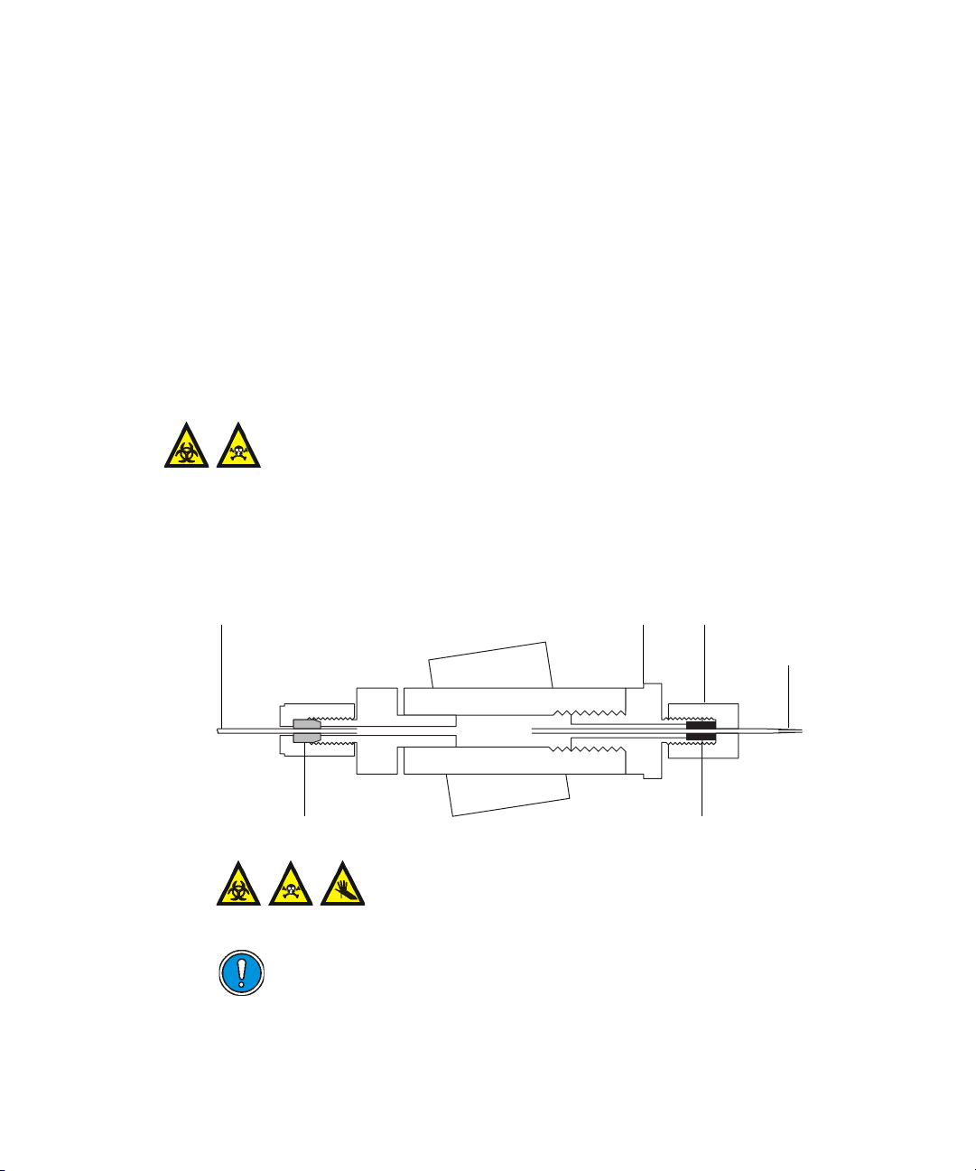
5. Place the sprayer (with gas line fitted) on the platform, and secure it
with the thumbscrew.
6. Refit the safety cover.
Fitting and loading the glass capillary
Required materials
• Chemical-resistant, powder-free gloves
• Fused silica syringe needle or a GELoader
To fit and load the glass capillary
Warning: The source components can be contaminated with
biohazardous and/or toxic materials. Always wear
f
chemical-resistant, powder-free gloves while performing this
procedure.
1. Unscrew the union at the front of the sprayer, and remove the sprayer’s
front section.
®
tip
PTFE “backpressure” tubing
Blue conductive elastomerFerrule
Knurled nutUnion
Glass capillary
Warning: To avoid injury with a sliver of glass
contaminated with toxic samples, do not touch the
sharp end of the capillary.
Caution: The capillaries are extremely fragile. Handle them with
great care from their square-cut ends. Touching their sharp end
can render the needle inoperable.
Optional glass capillary sprayer 4-9
Page 76

2. Carefully remove the capillary from its case by lifting it vertically while
pressing down on the foam with two fingers.
3. Over the square-cut end of the capillary, pass first the knurled nut, then
approximately 5 mm of conductive elastomer, and finally the union.
Union
Knurled nut
Elastomer
Glass capillary
4. Finger tighten the nut onto the union.
5. Ensure that the tip of the glass capillary protrudes about 7 mm from the
front of the knurled nut, as measured from the end of the nut to the
shoulder of the glass capillary, and then full tighten the nut onto the
union.
Union Knurled nut
7 mm
Glass capillary
6. Load sample into the capillary using either a fused silica syringe needle
or a GELoader tip.
Tip: Shake the loaded capillary to move the liquid to the tip of the
sprayer.
7. With the sprayer mounted on the adjuster platform, screw the union
back into the assembly; finger-tight is sufficient.
8. In the MassLynx Tune window ensure the Capillary parameter is set to
0V.
9. Push the sprayer platform into the source (see page 4-5).
4-10 Configuring the NanoLockSpray source
Page 77

To optimize the glass capillary sprayer
Warning: To avoid eye injuries, always wear eye protection when cutting
fused silica.
Warning: To avoid injury from trace chemicals on the probe, always
wear chemical-resistant, powder-free gloves.
1. Set the NanoFlow gas pressure to 0.3 bar and the cone gas to 40 L/h.
2. Ascertain that sample is flowing by observing a droplet on the tip.
Tip: If you cannot observe a droplet, increase the pressure briefly, up to
a maximum of 1.5 bar, and then return the pressure to 0.3 bar.
3. If you observe a droplet, continue the procedure at step 9.
Requirement: If you do not observe a droplet, in the MassLynx Tune
window, ensure the Capillary parameter is set to 0 V, and follow step 4
through step 8.
4. Move the sprayer back and to the left-hand side until the tip aligns with
the groove on the cone.
Tip: Aligning is best done while viewing from the front of the source.
5. While watching the camera image, carefully move the tip forward
toward the groove, until it touches, and a small piece of the glass
capillary shears off.
Glass capillary
Groove
Optional glass capillary sprayer 4-11
Page 78

6. Return the sprayer to its previous position.
7. Ascertain that sample is flowing by observing a droplet on the tip.
Tip: If you cannot observe a droplet, increase the pressure briefly, up to
a maximum of 1.5 bar, and then return the pressure to 0.3 bar.
8. If you observe a droplet, continue the procedure at step 9.
Requirement: If you do not observe a droplet, repeat step 4 through
step 8.
If, after you repeat step 4 through step 8, you still cannot observe a
droplet, discard the glass capillary and fit a new one (see page 4-9).
9. Set the capillary voltage slider to between 1.0 and 3.0 kV.
10. With an ion beam now visible on the peak display, optimize the sprayer
position and capillary voltage for maximum signal intensity.
Tip: The spray optimizes between 1.0 and 3.0 kV. To stop the sprayer,
set the capillary voltage to 0.
4-12 Configuring the NanoLockSpray source
Page 79

5 Maintenance Procedures
This chapter provides the maintenance guidelines and procedures
necessary to maintain the instrument’s performance.
Keep to a maintenance schedule, and perform maintenance as required
and described in this chapter.
Contents
Topic Page
Maintenance schedule 5-3
Spare parts 5-4
Troubleshooting using Connections Insight 5-5
Safety and handling 5-6
Preparing the instrument for work performed on its source 5-7
Removal and refitting of the source enclosure 5-8
Installing and removing the corona pin 5-12
Operating the source isolation valve 5-15
Removing O-rings and seals 5-17
Cleaning the mass spectrometer case 5-18
Emptying the nitrogen exhaust trap bottle 5-19
Cleaning the source components 5-21
Cleaning the sampling cone assembly 5-21
Cleaning the extraction cone 5-31
Cleaning the ion block assembly 5-38
Cleaning the source T-Wave ion guide assembly 5-49
Replacing the ESI probe tip and gasket 5-55
Replacing the ESI probe sample capillary 5-59
Cleaning the APCI probe tip 5-67
Replacing the APCI probe sample capillary 5-68
Replacing the LockSpray probe capillary 5-74
5-1
Page 80

Contents(continued)
Topic Page
Replacing the NanoLockSpray reference probe capillary 5-78
Cleaning or replacing the corona pin 5-83
Replacing the APCI probe heater 5-84
Replacing the ion block source heater 5-87
Replacing the LockSpray source assembly seals 5-91
Replacing the mass spectrometer’s air filter 5-95
Replacing the IntelliStart Fluidics tubing 5-98
5-2 Maintenance Procedures
Page 81

Maintenance schedule
The following table lists periodic maintenance schedules that ensure optimum
instrument performance.
Maintenance schedule
Procedure Frequency For information...
Clean the instrument case. As required. See page 5-18.
Empty the nitrogen exhaust
trap bottle.
Replace the oil-free (scroll)
pump’s seals.
Check daily, empty as
required.
Annually. See Edwards
See page 5-19.
document XDS35i
Instruction Manual
A730-01-880.
Clean the source components. When sensitivity
decreases to
unacceptable levels.
Replace the ESI probe tip. When sensitivity
decreases to
unacceptable levels.
Replace the ESI probe
capillary.
Clean the APCI probe tip.
(Options using the APCI
probe only.)
Replace the APCI probe
capillary.
Replace the LockSpray probe
capillary.
When sensitivity
decreases to
unacceptable levels or
sample flow is
inconsistent.
When sensitivity
decreases to
unacceptable levels.
When sensitivity
decreases to
unacceptable levels or
sample flow is
inconsistent.
Annually. See page 5-74.
See page 5-21.
See page 5-55.
See page 5-59.
See page 5-67.
See page 5-68.
Maintenance schedule 5-3
Page 82

Maintenance schedule (continued)
Procedure Frequency For information...
Clean or replace the corona
pin (APCI and ESCi modes).
Replace the APCI probe
heater.
Replace the ion block heater
cartridge.
Replace the source assembly
seals.
Replace the mass
spectrometer air filters.
Replace the IntelliStart
Fluidics tubing.
Spare parts
When the corona pin is
corroded or black, or
the sensitivity
decreases to
unacceptable levels.
If the heater fails to
heat the probe.
If the heater fails to
heat the ion block.
Annually. See page 5-91.
Annually. See page 5-95.
In the event of
blockage in the tubing
connections between
the IntelliStart
Fluidics system
components.
See page 5-83.
See page 5-84.
See page 5-87.
See page 5-98.
Replace only the parts mentioned in this document. For spare parts details,
see the Waters Quality Parts Locator on the Waters Web site’s
Services/Support page.
5-4 Maintenance Procedures
Page 83

Troubleshooting using Connections Insight
Connections Insight® is an “intelligent” device management (IDM) Web
service that enables Waters to provide proactive service and support for the
ACQUITY UPLC system. Before you can use Connections Insight, a Waters
technician must install its service agent software on your MassLynx
workstation. In a client/server system, the service agent must also be installed
on the computer from which you control the system. The service agent
software automatically and securely captures and sends information about
the support needs of your system directly to Waters.
If you encounter a performance issue as you are using the Instrument Console
software, you can also manually submit a Connections Insight request to
Waters customer support.
As an option, Remote Desktop is a real-time collaboration tool, a service that
controls two-way connection with the ACQUITY UPLC system by enabling
the Connections INSIGHT iAssist service level.
Consult any of these sources for more information about Connections Insight
and Connections INSIGHT iAssist:
• http://www.waters.com
• Your sales representative
• Your local Waters subsidiary
• Waters Customer Support
To submit a Connections Insight request
1. Select Troubleshoot > Submit Connections Insight request.
2. In the Connections Insight Request dialog box, type your name,
telephone number, e-mail address, and a description of the problem.
3. Click Submit and allow approximately 5 minutes to save the service
profile.
Result: A .zip file containing your Connections Insight profile is
forwarded to Waters customer support for review. Note that saving a
service profile or plot file using the Instrument Console software can
require as much as 150 MB of file space.
Troubleshooting using Connections Insight 5-5
Page 84
Safety and handling
Bear in mind the following safety considerations when performing
maintenance procedures:
Warning: The instrument components can be contaminated with
biologically hazardous materials. Always wear chemical-resistant,
powder-free gloves while handling the components.
Warning: To prevent injury, always observe Good Laboratory Practices
when handling solvents, changing tubing, or operating the instrument.
Know the physical and chemical properties of the solvents used, see the
Material Safety Data Sheets for the solvents in use.
Warning: To avoid electric shock,
• do not remove the instrument’s panels. There are no user-serviceable
items inside the instrument.
• ensure that the instrument is in Standby mode before commencing
any maintenance.
Warning: The probe and source can be hot. To avoid burn injuries, take
great care while working with these components.
Warning: To avoid puncture wounds, take great care while working with
the source enclosure open if one or both of these conditions apply:
• An ESI probe is fitted (the probe tip is sharp).
• A corona pin is fitted (the pin tip is sharp).
See Appendix A, “Safety Advisories” for safety advisory information.
5-6 Maintenance Procedures
Page 85

Preparing the instrument for work performed on its source
Warning: Follow the procedure described below before working on the
source (for example, when changing the probe, installing or removing
the corona pin, operating the source isolation valve, and when
maintaining the source).
To prepare the instrument
1. In the Instrument Console, click Stop Flow to stop the LC flow or, if
column flow is required, divert the LC flow to waste as follows:
a. In the Instrument Console system tree, expand SYNAPT G2
Detector, Interactive Fluidics.
b. Click Control .
c. Select Waste as the flow state.
2. In the Instrument Console, click Standby .
3. Set the source temperature to 30 °C.
4. Wait 30 minutes to allow the desolvation gas flow to cool the probe and
source.
5. In the Instrument Console, ensure that the API desolvation gas flow is
stopped.
Preparing the instrument for work performed on its source 5-7
Page 86
Removal and refitting of the source enclosure
The following procedures apply to both the standard and optional source
enclosures.
You must remove the LockSpray or NanoLockSpray source enclosure from the
instrument before performing certain maintenance procedures or fitting the
optional dual-mode APPI/APCI source.
Removing the source enclosure from the instrument
Required materials
Chemical-resistant, powder-free gloves
To remove the source enclosure
Warning: The source components can be contaminated with
biohazardous and/or toxic materials. Always wear
chemical-resistant, powder-free gloves while performing this
procedure.
Warning: To avoid electric shock, prepare the instrument for work
performed on its source before commencing this procedure.
1. Prepare the instrument for work performed on its source (see page 5-7).
Warning: The probe and source can be hot. To avoid burn injuries,
take great care while working with these components.
2. Remove the probe from the source.
• If you are removing an ESI probe, see page 3-7.
• If you are removing an APCI probe, see page 3-18.
3. Slide open the instrument’s source interface door (see the figure on
page 3-5).
5-8 Maintenance Procedures
Page 87
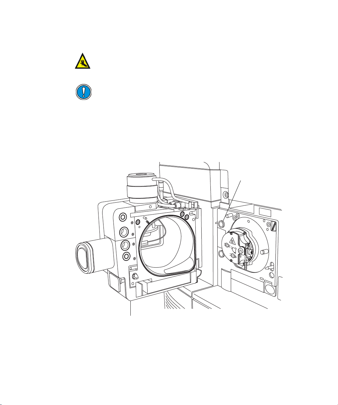
4. Disconnect the source enclosure cables from the instrument’s
connectors.
Warning: The corona pin tip is sharp. To avoid puncture wounds,
take great care while working with the source enclosure open if a
corona pin is fitted.
Caution: To avoid damaging the sample inlet when removing a
NanoLockSpray source enclosure, move the sprayer platform out
of the source enclosure before opening it (see page 4-5).
5. Pull the source enclosure release (located at the bottom, right-hand side)
outwards, and swing open the enclosure.
6. Using two hands, grasp the source enclosure, and lift it vertically off the
two supporting studs on the source adaptor housing.
Supporting stud
Source enclosure
Removal and refitting of the source enclosure 5-9
TP03164
Page 88
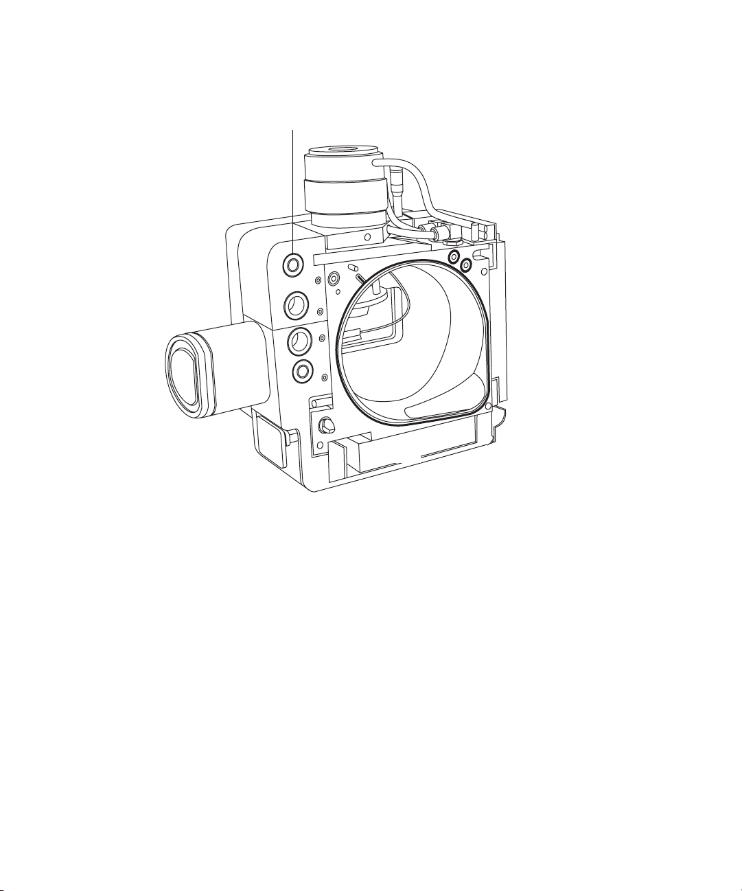
7. Store the cables neatly by plugging them into the cable-storage positions
on the rear of the source enclosure.
Cable storage positions
5-10 Maintenance Procedures
Page 89
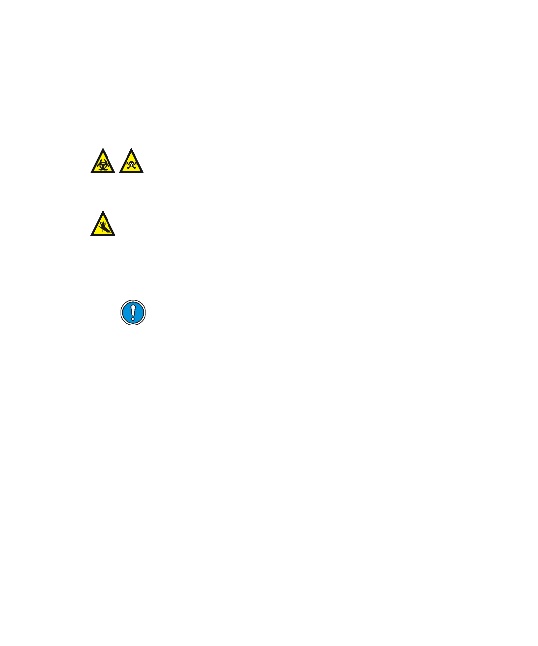
Fitting the source enclosure to the instrument
Required materials
Chemical-resistant, powder-free gloves
To fit the source enclosure to the instrument
Warning: The source components can be contaminated with
biohazardous and/or toxic materials. Always wear
chemical-resistant, powder-free gloves while performing this
procedure.
Warning: To avoid puncture wounds, take great care while fitting the
source enclosure to the source if a corona pin is fitted (the pin tip is
sharp).
1. Using two hands, fit the source enclosure to the two supporting studs on
the source adaptor housing.
Caution: To avoid damaging the sample inlet when fitting a
NanoLockSpray source enclosure, move the sprayer platform out
of the source enclosure before closing it (see page 4-5).
2. Close the source enclosure.
3. Connect the source enclosure cables to the instrument’s connectors.
Tip: The cables and connectors are color coded; the blue-sleeved cable
connects to the blue connector and the yellow-sleeved cable to the yellow
connector.
4. Slide closed the instrument’s source interface door.
Removal and refitting of the source enclosure 5-11
Page 90

Installing and removing the corona pin
For APCI, ESCi, and dual-mode APPI/APCI operation, a corona pin must be
fitted to the source.
Installing the corona pin in the source
Required materials
Chemical-resistant, powder-free gloves
To install the corona pin in the source
Warning: The LC system connections, ESI probe, and source can
be contaminated with biohazardous and/or toxic materials. Always
wear chemical-resistant, powder-free gloves while performing this
procedure.
Warning: To avoid electric shock, prepare the instrument for work
performed on its source before commencing this procedure.
1. Prepare the instrument for work performed on its source (see page 5-7).
Warning: The source can be hot. To avoid burn injuries, take great
care while working with the source enclosure open.
Warning: The ESI probe tip is sharp. To avoid puncture wounds,
take great care while working with the source enclosure open if an
ESI probe is fitted.
2. Pull the source enclosure release (located at the bottom, right-hand side)
outwards, and swing open the enclosure.
3. Remove the blanking plug from the corona pin mounting contact.
Tip: Store the blanking plug in a safe location.
5-12 Maintenance Procedures
Page 91
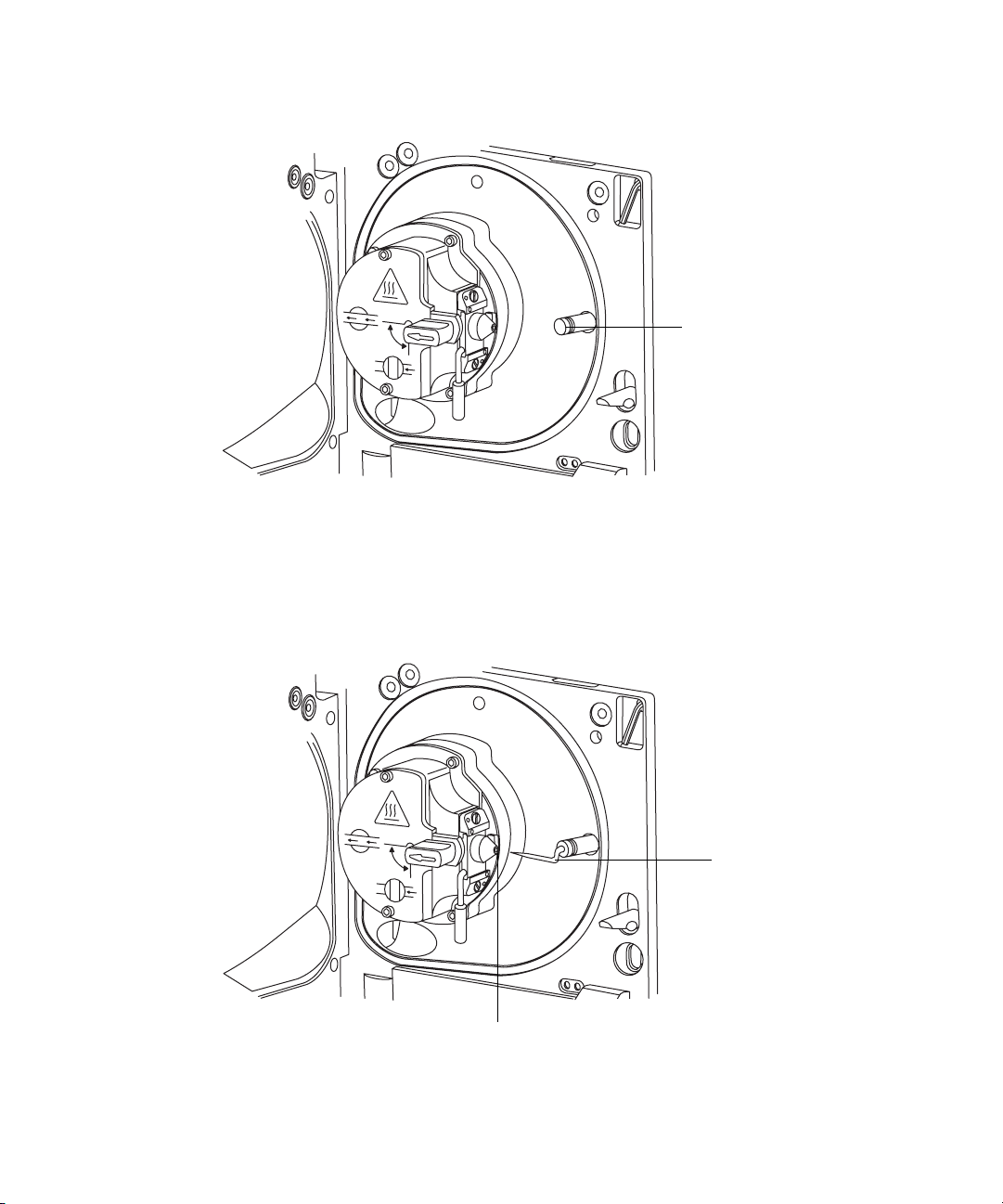
Corona pin mounting contact
Corona pin mounting
contact blanking plug
TP03130
4. Fit the corona pin to the corona pin mounting contact.
Requirement: Ensure that the corona pin is securely mounted and that
its tip aligns with the sample cone orifice.
Corona pin
Corona pin
TP03130
Sample cone orifice
Installing and removing the corona pin 5-13
Page 92

5. Close the source enclosure.
6. Look through the source window, and using the vernier probe adjuster
(see the figure on page 3-4), position the ESI probe tip so that it is
pointing, approximately, midway between the tips of the sample cone
and corona pin.
Removing the corona pin from the source
Required materials
Chemical-resistant, powder-free gloves
To remove the corona pin from the source
Warning: The LC system connections, ESI probe, and source can
be contaminated with biohazardous and/or toxic materials. Always
wear chemical-resistant, powder-free gloves while performing this
procedure.
Warning: To avoid electric shock, prepare the instrument for work
performed on its source before commencing this procedure.
1. Prepare the instrument for work performed on its source (see page 5-7).
Warning: The source can be hot. To avoid burn injuries, take great
care while working with the instrument’s source enclosure open.
Warning: The ESI probe tip is sharp. To avoid puncture wounds,
take great care while working with the source enclosure open if an
ESI probe is fitted.
2. Pull the source enclosure release (located at the bottom, right-hand side)
outwards, and swing open the enclosure.
3. Remove the corona pin from its mounting contact (see the figure on
page 5-13).
Tip: Store the corona pin in a safe location.
4. Fit the blanking plug to the corona pin mounting contact
5. Close the source enclosure.
5-14 Maintenance Procedures
Page 93
Operating the source isolation valve
You must close the source isolation valve to isolate the source from the
instrument vacuum system for certain maintenance procedures.
Required materials
Chemical-resistant, powder-free gloves
To close the source isolation valve before starting a maintenance procedure
Warning: The source components can be contaminated with
biohazardous and/or toxic materials. Always wear
chemical-resistant, powder-free gloves while performing this
procedure.
Warning: To avoid electric shock, prepare the instrument for work
performed on its source before commencing this procedure.
1. Prepare the instrument for work performed on its source (see page 5-7).
Warning: The source can be hot. To avoid burn injuries, take great
care while working with the instrument’s source enclosure open.
Warning: To avoid puncture wounds, take great care while
working with the source enclosure open if one or both of these
conditions apply:
• An ESI probe is fitted (the probe tip is sharp).
• A corona pin is fitted (the pin tip is sharp).
2. Pull the source enclosure release (located at the bottom, right-hand side)
outwards, and swing open the enclosure.
Operating the source isolation valve 5-15
Page 94
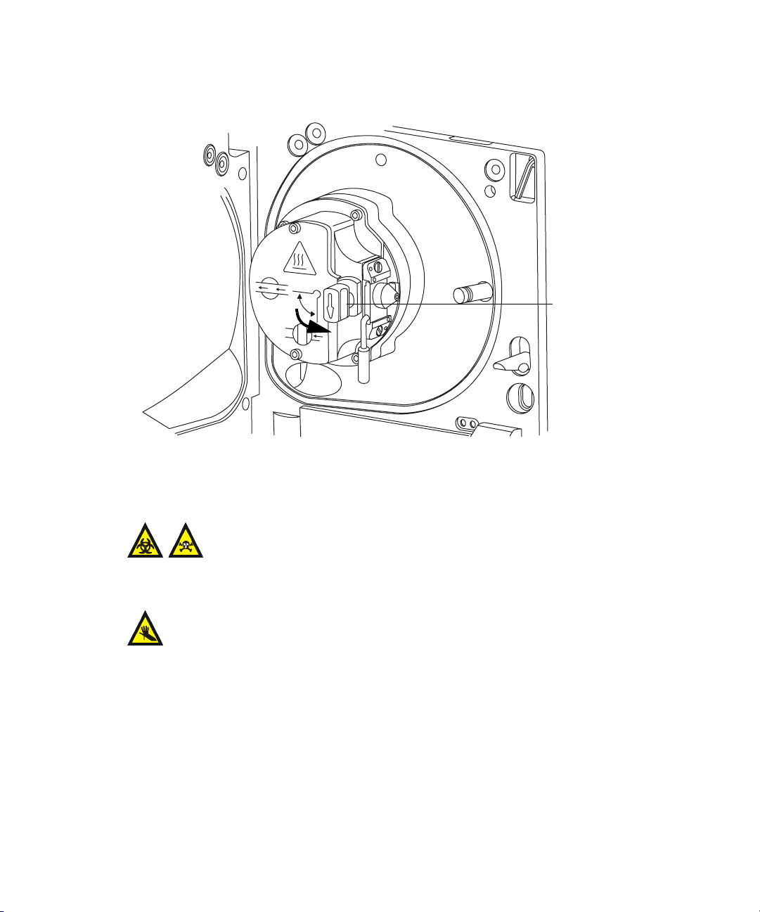
3. Close the source isolation valve by moving its handle counterclockwise,
to the vertical position.
Isolation valve handle
in closed position
TP03130
To open the source isolation valve after completing a maintenance
procedure
Warning: The source components can be contaminated with
biohazardous and/or toxic materials. Always wear
chemical-resistant, powder-free gloves while performing this
procedure.
Warning: To avoid puncture wounds, take great care while working with
the source enclosure open if one or both of these conditions apply:
• An ESI probe is fitted (the probe tip is sharp).
• A corona pin is fitted (the pin tip is sharp).
5-16 Maintenance Procedures
Page 95

1. Open the source isolation valve by moving its handle clockwise to the
horizontal position.
2. Close the source enclosure.
Removing O-rings and seals
Isolation valve handle
in open position
TP03130
When performing certain maintenance procedures, you must remove O-rings
or seals from instrument components. An O-ring removal kit accompanies the
instrument.
O-ring removal kit
Tool 1
To o l 2
Removing O-rings and seals 5-17
Page 96

To remove an O-ring
Caution: When removing an O-ring or seal from a component, be careful
not to scratch the component with the removal tool.
Use the tools as aids to pull the O-ring or seal from its groove.
Tip: If the O-ring or seal is not going to be reused, you can use the forked end
of tool 1 to impale the O-ring or seal, and aid its removal.
Cleaning the mass spectrometer case
Caution: Do not use abrasives or solvents to clean the instrument’s case.
Using a soft cloth, dampened with water, clean the outside surfaces of the
mass spectrometer.
5-18 Maintenance Procedures
Page 97
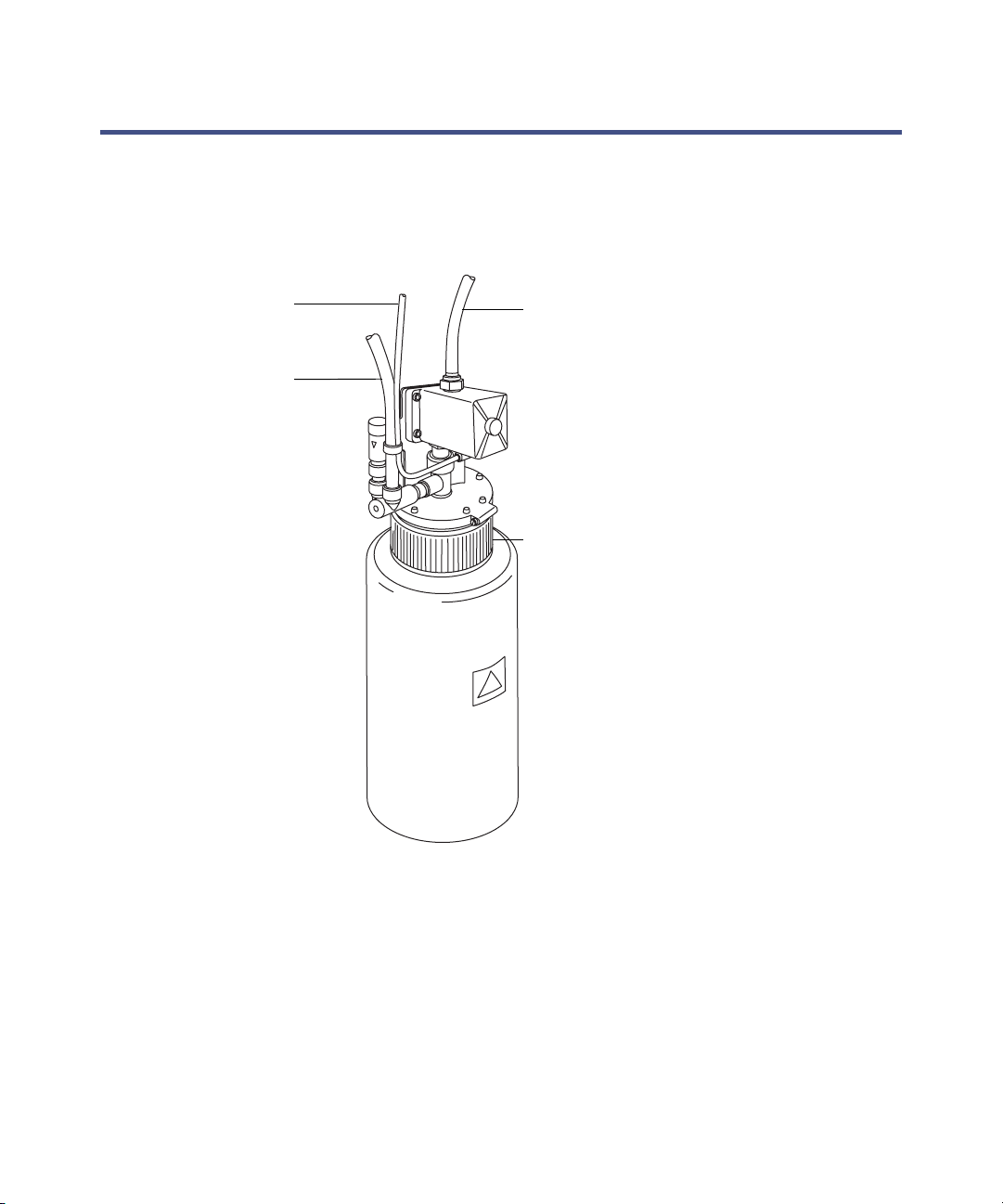
Emptying the nitrogen exhaust trap bottle
Inspect the nitrogen exhaust trap bottle in the instrument exhaust line daily,
and empty it before it is more than approximately 10% full.
Nitrogen exhaust trap bottle
From instrument
pilot valve port
From instrument
exhaust connection
Nitrogen exhaust
trap bottle
To laboratory
exhaust port
Cap
Required materials
Chemical-resistant, powder-free gloves
TP03164
Emptying the nitrogen exhaust trap bottle 5-19
Page 98
To empty the nitrogen exhaust trap bottle
1. In the Instrument Console, click Stop Flow .
2. Pull the source enclosure release (located at the bottom, right-hand side)
outwards, and swing open the enclosure.
Warning: The waste liquid in the nitrogen exhaust trap
bottle comprises ACQUITY UPLC solvents and samples.
Always wear chemical-resistant, powder-free gloves while
handling it.
3. Unscrew and remove the nitrogen exhaust trap bottle from the cap and
associated fittings.
Warning: The waste liquid can be contaminated with
biohazardous and/or toxic materials. Dispose of it according
to local environmental regulations.
4. Dispose of the waste liquid in accordance with local environmental
regulations.
5. Fit and tighten the nitrogen exhaust trap bottle to the cap.
6. Secure the nitrogen exhaust trap bottle in the upright position.
7. Close the source enclosure.
Tip: An automatic pressure test is performed.
8. In the Instrument Console, click Start Flow .
5-20 Maintenance Procedures
Page 99

Cleaning the source components
Clean the sample cone and cone gas nozzle (see page 5-21) when these
conditions apply:
• The sample cone and cone gas nozzle are visibly fouled.
• LC and sample-related causes for decreased signal intensity have been
dismissed.
If cleaning the sample cone and cone gas nozzles fails to increase signal
sensitivity, also clean the extraction cone (see page 5-31).
If cleaning the extraction cone fails to increase signal sensitivity, clean the ion
block and isolation valve (see page 5-38).
If cleaning the ion block and isolation valve fails to increase signal sensitivity,
also clean the source T-Wave ion guide assembly (see page 5-49).
Cleaning the sampling cone assembly
You can remove the sampling cone assembly (comprising the sample cone,
O-ring, and cone gas nozzle) for cleaning without venting the instrument.
Removing the sampling cone assembly from the source
Required materials
Chemical-resistant, powder-free gloves
Cleaning the source components 5-21
Page 100
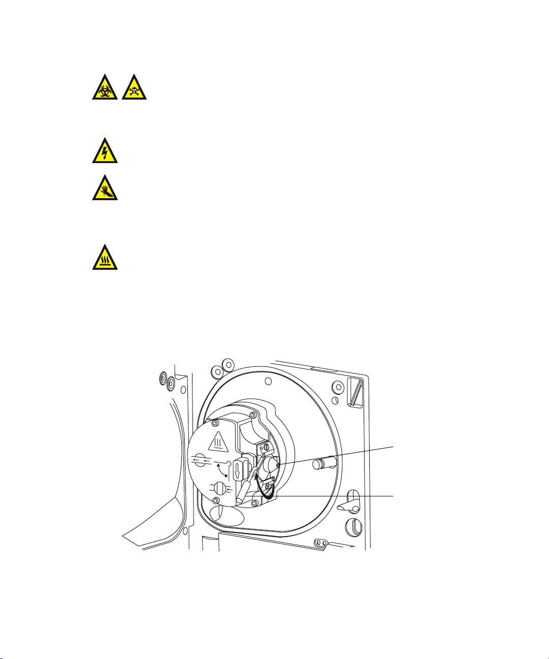
To remove the sampling cone assembly from the source
Warning: The source components can be contaminated with
biohazardous and/or toxic materials. Always wear
chemical-resistant, powder-free gloves while performing this
procedure.
Warning: To avoid electric shock, ensure that the instrument is in
Standby mode before commencing this procedure.
Warning: To avoid puncture wounds, take great care while working with
the source enclosure open if one or both of these conditions apply:
• An ESI probe is fitted (the probe tip is sharp).
• A corona pin is fitted (the pin tip is sharp).
Warning: The source can be hot. To avoid burn injuries, take great care
while working with the source enclosure open.
1. Close the source isolation valve (see page 5-15).
2. Grasp the cone gas nozzle handle, and use it to rotate the sampling cone
assembly 90 degrees, moving the handle from the vertical to the
horizontal position.
5-22 Maintenance Procedures
Sampling cone
assembly
Cone gas nozzle
handle
TP03131
 Loading...