

Page 1
[ Care and Use ManUal ]
sunFire Columns
Contents
I. GETTING STARTED
a. Column Installation
b. Column Equilibration
c. Initial Column Efficiency Determination
II. COLUMN USE
a. Guard Columns
b. Sample Preparation
c. pH Range
d. Solvents
e. Pressure
f. Temperature
III. SCALING UP/DOWN ISOCRATIC METHODS
IV. TROUBLESHOOTING
V. COLUMN CLEANING, REGENERATING AND STORAGE
a. Cleaning and Regenerating
b. Storage
VI. CONNECTING THE COLUMN TO THE HPLC SYSTEM
a. Column Connectors and System Tubing Considerations
b. Bandspreading Minimization
c. Measuring System Bandspreading Volume & System Variance
d. Measuring System Volume
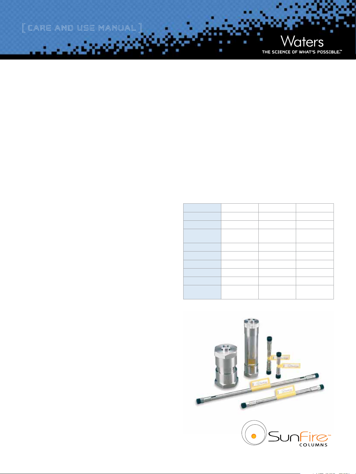
Thank you for choosing a SunFire
™
column. The SunFire packing
materials were designed to provide excellent peak shape, minimal
column bleed, and high mass loading. The SunFire packing materials
are manufactured in an ISO 9000 certified plant using ultra pure
reagents. Each batch of SunFire material is tested chromatographically with acidic, basic and neutral analytes and the results are held
to narrow specification ranges to assure excellent, reproducible
performance. Every column is individually tested and a Performance
Chromatogram is provided with each column along with the Certificate
of Batch Analysis.
SunFire Column Physical Characteristics
Chemistry C
USP Class No. L1 L7 L3
Particle Shape Spherical Spherical Spherical
Particle Sizes
Pore Size 100Å 100Å 100Å
Surface Area 340 m
Carbon Load 16% 12% N/A
Endcapped Yes Yes N /A
ph Range 2-8 2-8 N/A
Temperature
Limits
18
2.5, 3.5,
5, 10 µm
2
/g 340 m2/g 340 m2/g
Low pH = 50 ˚C
High pH = 40 ˚C
C
8
2.5, 3.5,
5, 10 µm
Low pH = 40 ˚C
High pH = 40 ˚C
Silica
5, 10 µm
N/A
VII. ADDITIONAL INFORMATION
a. Use of Narrow-Bore (≤3.0 mm i.d.) Columns
b. Impact of Bandspreading Volume on 2.1 mm i.d.
Column Performance
c. Non-Optimized vs. Optimized LC/MS/MS System:
System Modification Recommendations
Page 2

[ Care and Use ManUal ]
I. GETTING STARTED
Each SunFire column comes with a Performance Test Chromatogram.
This Performance Test Chromatogram is specific to each individual
column and contains the following information: gel batch number,
column serial number, USP plate count, USP tailing factor, capacity
factor, and chromatographic conditions. The performance test chromatogram should be stored for future reference.
a. Column Installation
Note: Flow rates given in the procedure below are for a typical 4.6
mm i.d. column. Scale the flow rate up or down accordingly based
upon the column i.d., length, particle size, and backpressure of the
SunFire column being installed. See “Scaling Up/Down Isocratic
Separations” for calculating flow rates when changing column i.d.
and/or length. See “Connecting the Column to the HPLC System” for a
more detailed discussion on HPLC connections.
Reversed-phase Columns (SunFire C
1. Purge the pumping system of any buffer-containing mobile
phases and connect the inlet end of the column to the
injector outlet.
and SunFire C8)
18
4. Connect the column and equilibrate it with the mobile phase.
Note: Equilibration with the mobile phase may require a larger amount
of solvent than in reversed-phase chromatography.
b. Column Equilibration
SunFire columns are shipped in 100% acetonitrile. It is important
to ensure mobile phase compatibility before changing to a different
mobile-phase system. Equilibrate the column with a minimum of 10
column volumes of the mobile phase to be used (refer to Table 1 for
a listing of empty column volumes).
Reversed-phase (SunFire C
To avoid precipitating out mobile-phase buffers on your column or in
your system, flush the column with five column volumes of a water/
organic solvent mixture, using the same or lower solvent content as in
the desired buffered mobile phase. (For example, flush the column and
HPLC system with 60% methanol in water prior to introducing 60%
methanol/40% buffer mobile phase.)
Note: If mobile-phase additives are present in low concentrations (e.g.,
ion-pairing reagents), 100 to 200 column volumes may be required
for complete equilibration.
or SunFire C8) Columns
18
2. Flush column with 100% organic mobile phase (methanol or
acetonitrile) by setting the pump flow rate to 0.1 mL/min and
increase the flow rate to 1 mL/min over 5 minutes.
3. When the mobile phase is flowing freely from the column outlet,
stop the flow and attach the column outlet to the detector. This
prevents entry of air into the detection system and gives more
rapid baseline equilibration.
4. Gradually increase the flow rate as described in step 2.
5. Once a steady backpressure and baseline have been achieved,
proceed to the next section.
Normal-phase Columns (SunFire Silica)
Note: It is assumed that your system has been used for reversed-phase
chromatography. If this is not the case, you can start with step 3.
1. Purge the pumping system of any buffer-containing mobile phases.
2. Flush the system thoroughly with acetonitrile.
3. Switch the system over to the mobile phase that you are planning
to use in normal-phase chromatography.
Normal-phase Columns (SunFire Silica)
SunFire normal-phase (NP) columns are delivered in 96% heptane/
4% isopropyl alcohol. Care should be taken not to pass any mobile phase
through the column that might cause a precipitate (see above). SunFire
Silica normal-phase columns are compatible with water and all common
organic solvents, provided that solvent miscibility is accounted for.
Equilibrate normal-phase silica columns in the mobile phase. Very
small quantities of water in the mobile phase can dramatically affect
the activity of normal-phase packings. For good reproducibility,
ensure that the mobile phase always has the same water content.
It is difficult and usually unnecessary to completely eliminate the
water from the mobile phase. Dry mobile phases can take a very long
time to equilibrate the column. A water content of 50 percent of
saturation is recommended for most applications.
To equilibrate your column:
1. Starting at 0.0 mL/min, increase the flow rate in
0.1 mL/min increments to 1.0 min.
2
Page 3

[ Care and Use ManUal ]
2. Purge the column with the mobile phase until you obtain a stable
baseline.
3. Verify that retention times and peak areas for a standard are
stable by comparing 2-3 replicate, consecutive injections.
Before you perform the first analysis on your new column, perform an
efficiency test to confirm the performance of the column.
c. Initial Column Efficiency Determination
1. Perform an efficiency test on the column before using it. Waters
recommends using a suitable solute mixture, as found in the
“Performance Test Chromatogram”, to analyze the column upon
receipt. However, if the column is used only for a single routine
isocratic assay, it may be more convenient to test the column
under these assay conditions. Keep a record of the initial column
performance.
2. Determine the number of theoretical plates (N) and use this value
for periodic comparisons.
3. Repeat the test at predetermined intervals to track column
performance over time. Slight variations may be obtained on
two different HPLC systems due to the quality of the connections,
operating environment, system electronics, reagent quality,
column condition and operator technique.
Table 1. Empty Column Volumes in mL (multiply by 10 for flush
solvent volumes)
Column
Length
20 mm - 0.07 0.14 0.33 - - - - 30 mm - 0.1 0.2 0.5 - 2.4 8 - 50 mm 0.1 0.2 0.3 0.8 2.4 4 14 35 98
100 mm 0 .1 0.4 0.7 1.7 5 8 28 70 196
150 mm 0.1 0.5 1.0 2.5 7 12 42 106 294
250 mm - 0.9 1.8 4 - 20 70 176 490
1.0 2 .1 3.0 4.6 7.8 10 19 30 50
Column Internal Diameter (nm)
II. COLUMN USE
To ensure the continued high performance of SunFire columns, follow
these guidelines:
a. Guard Columns
Use a SunFire guard column of matching chemistry and particle size
between the injector and main column. It is important to use a matching
guard column to protect the main column while not compromising or
changing the analytical resolution. Guard columns need to be replaced
at regular intervals as determined by sample contamination. When
system backpressure steadily increases above a set pressure limit, it
is usually an indication that the guard column should be replaced. A
sudden appearance of split peaks or other changes in chromatographic
performance is also indicative of a need to replace the guard column.
b. Sample Preparation
1. Sample impurities often contribute to column contamination.
®
One option to avoid this is to use Oasis
®
cartridges/columns or Sep-Pak
cartridges of the appropriate
chemistry to clean up the sample before analysis. Link to
www.waters.com/sampleprep
2. It is preferable to prepare the sample in the operating mobile
phase or a mobile phase that is weaker (less organic modifier
in the case of reversed-phase chromatography, less polar
modifier in the case of normal-phase chromatography or
hydrophilic interaction chromatography, less salt in the case
of ion exchange) than the mobile phase for the best peak shape
and sensitivity.
3. If the sample is not dissolved in the mobile phase, ensure that the
sample, solvent and mobile phases are miscible in order to avoid
sample and/or buffer precipitation. Filter sample with 0.2 μm
membranes to remove particulates. If the sample is dissolved in a
solvent that contains an organic modifier (e.g., acetonitrile,
methanol, etc.) ensure that the membrane material does not
dissolve in the solvent. Contact the membrane manufacturer with
solvent compatibility questions. Alternatively, centrifugation for
20 minutes at 8,000 rpm, followed by the transfer of the
supernatant liquid to an appropriate vial, could be considered.
solid-phase extraction
3
Page 4

[ Care and Use ManUal ]
c. pH Range
The recommended operating pH range for SunFire columns is 2 to 8. A listing of commonly used buffers and additives is given in Table 2.
Additionally, the column lifetime will vary depending upon the operating temperature, and the type and concentration of buffer used. For
example, the use of phosphate buffer at pH 8 in combination with elevated temperatures will lead to shorter column lifetimes.
Table 2: Buffer Recommendations for Using SunFire Columns from pH 2 to 8
Additive or Buffer pK
Formic Acid 3.75 Volatile Yes
Acetic Acid 4.76 Volatile Yes
Ammonium Formate
COOH)
(NH
4
Trifuoroacetic Acid (TFA) 0.30 Volatile Low conc.
Ammonium Acetate
(NH4CH2COOH)
Phosphate 1 2.15 1.15 - 3.15 Non-volatile No Traditional low pH buffer, good UV transparency.
Phosphate 2 7.20 6.20 - 8.20 Non-volatile No
Buffer Range
a
(±1 pH unit)
3.75 2.75 - 4.75 Volatile Yes
4.76 2.75 - 5.76 Volatile Yes
Volatility
d. Solvents
To maintain maximum column performance, use high quality
chromatography grade solvents. Filter all aqueous buffers prior to
®
use. Pall Gelman Laboratory Acrodisc
(Please refer to the filtration section of the Waters Chromatography
filters are recommended.
Used for
Mass
Spec?
Comments
Maximum buffering obtained when used with Ammonium Formate salt.
Used in 0.1-1.0% range.
Maximum buffering obtained when used with Ammonium Acetate salt.
Used in 0.1-1.0% range.
Used in the 1-10 mM range for LC/MS. Higher concentrations (typically 20 mM)
are recommended for UV applications.
Note: sodium or potassium salts are not volatile.
When used in LC/MS, due to signal supression, it is generally recommended to
use TFA at concentrations < 0.1%.
Used in the 1-10 mM range for LC/MS. Higher concentrations (typically 20 mM)
are recommended for UV applications.
Note: sodium or potassium salts are not volatile.
Above pH 7, reduce temperature/concentration and use guard column to
maximize lifetime.
e. Pressure
SunFire columns can tolerate pressures of up to 6,000 psi (400 bar or
40 MPa) although long-term, routine operating pressures greater than
4,000 – 5,000 psi should be avoided in order to maximize column
and system lifetimes.
Columns and Supplies Catalog or the Waters web site (www.waters.
com) for additional product information.) Solvents containing
suspended particulate materials will generally clog the outside
surface of the inlet distribution frit of the column. This will result
in higher operating pressure and poorer performance. Degas all
solvents thoroughly before use to prevent bubble formation in
the pump and detector. The use of an on-line degassing unit is
f. Temperature
Temperatures between 20 ˚C – 50 ˚C are recommended for operating
SunFire columns at low pH in order to enhance selectivity, lower
solvent viscosity and increase mass transfer rates. However, any
temperature above ambient may have a negative effect on lifetime
which will vary depending on the pH and buffer conditions used.
also recommended. This is especially important when running low
pressure gradients since bubble formation can occur as a result of
aqueous and organic solvent mixing during the gradient.
4
Page 5

[ Care and Use ManUal ]
III. SCALING UP/DOWN ISOCRATIC METHODS
The following formulas will allow scale up or scale down, while
maintaining the same linear velocity, and provide new sample
loading values:
If column i.d. and length are altered:
= F1(r2/r1)2
F
2
or
Injection volume
= Injection volume2 (r2/r1)2(L2/L1)
1
Where: r = radius of the column, in mm
F = flow rate, in mL/min
L = length of column, in mm
1 = original, or reference column
2 = new column
IV. TROUBLESHOOTING
Changes in retention time, resolution, or backpressure are often due
to column contamination. See “Column Cleaning, Regenerating and
Storage”. A copy of the HPLC Troubleshooting Guide may be downloaded
at www.waters.com, in the “Search” field enter WA20769.
V. COLUMN CLEANING, REGENERATING AND STORAGE
Reversed-phase Columns (SunFire C
and SunFire C8)
18
Flushing with a neat organic solvent, taking care not to precipitate
buffers, is usually sufficient to remove most contaminant. If the
flushing procedure does not solve the problem, purge the column
using the following cleaning and regeneration procedures. Use the
cleaning routine that matches the properties of the samples and/or
what you believe is contaminating the column (see Table 3). Flush
columns with 20 column volumes of HPLC-grade solvents (e.g.,
80 mL total for 4.6 x 250 mm column). Increasing mobile-phase
temperature to 35-55 ˚C increases cleaning efficiency. If the column
performance is poor after regenerating and cleaning, call your local
Waters office for additional support.
Table 3: Column Sequence or Options
Polar Samples Non-polar Samples Proteinaceous Samples
1. Water
2. Methanol 2. Terahydrofuran (THF) Option 2: Gradient of
3. Tetrahydrofuran (THF)
4. Methanol 4. Hexane
5. Water
6. Mobile Phase 6. Mobile Phase
*Use low organic solvent content to avoid precipitating buffers.
1. Isopropanol (or an
appropriate isopropanol/
water mixture*)
3. Dichloromethane
5. Isopropanol (followed
by an appropriate isopropanol/water mixture*)
Option 1: Inject repeated
aliquots of dimethyl
sulfoxide (DMSO)
10% to 90% B where:
A = 0.1% trifluoroacetic
acid (TFA) in Water
B = 0.1% trifluoroacetic acid
(TFA) in acetonitrile (CH
Option 3: Flush column with
7 M guanidine hydrochloride,
or 7 M urea
CN)
3
a. Cleaning and Regenerating
Changes in peak shape, peak splitting, shoulders on the peak, shifts
in retention, change in resolution or increasing backpressure may
indicate contamination of the column. Changing the guard column
being used will often restore column performance. If not (or if
no guard column is being used), follow the procedures detailed
below. To prevent potential contamination from affecting detector
performance, it is recommended that any detector(s) be disconnected
from the effluent flow of the column during cleaning. Reversing
the direction of the flow through the column (backflushing) may
sometimes improve the effectiveness of any cleaning procedure.
Normal-phase Columns (SunFire Silica)
To regenerate, pump 20-30 column volumes each of dichloromethane
and isopropanol through the column. Other wash solvents such
as tetrahydrofurane (THF) may also be selected based on the
suspected contamination.
Guard columns need to be replaced at regular intervals, as determined
by sample contamination. When system backpressure steadily increases
above a set pressure limit, it is usually an indication that the guard
column should be replaced. A sudden appearance of split peaks is also
indicative of a need to replace the guard column.
5
Page 6
[ Care and Use ManUal ]
b. Storage
Completely seal the column to avoid evaporation and drying out of
the bed.
Reversed-phase Columns (SunFire C
For periods longer than four days at room temperature, store the
column (with the exception of cyano chemistry columns) in 100%
acetonitrile at room temperature. For elevated temperature applications, store immediately after use in 100% acetonitrile for the best
column lifetime. Do not store columns in buffered eluents. If the
mobile phase contained a buffer salt, flush the column with 10 column volumes of HPLC grade water (see Table 1 for common column
volumes) and replace with 100% acetonitrile for storage. Failure to
perform this intermediate step could result in precipitation of the
buffer salt in the column when 100% acetonitrile is introduced.
Normal-phase Columns (SunFire Silica)
For rapid equilibration upon start-up, store your normal-phase column
in the mobile phase that is commonly used.
and SunFire C8)
18
VI. CONNECTING THE COLUMN TO THE HPLC SYSTEM
a. Column Connectors and System Tubing Considerations
All SunFire columns have Waters-style endfittings.
Note: If one of the wrenches is improperly placed on the column tube
flat during this process, the endfitting will be loosened and leak.
3. If a leak occurs between the stainless steel compression screw
fitting and the column endfitting, a new compression screw
fitting, tubing and ferrule must be assembled.
4. An arrow on the column identification label indicates correct
direction of solvent flow. Correct connection of 1/16 inch
outer diameter stainless steel tubing leading to and from the
column is essential for high-quality chromatographic results. It
is important to realize that extra column peak broadening can
destroy a successful separation. The choice of appropriate column
connectors and system tubing is discussed in detail below. Due to
the absence of an industry standard, various column manufacturers have employed different types of chromatographic column
connectors. The chromatographic performance of the separation
can be negatively affected if the style of the column endfittings
does not match the existing tubing ferrule settings. This section
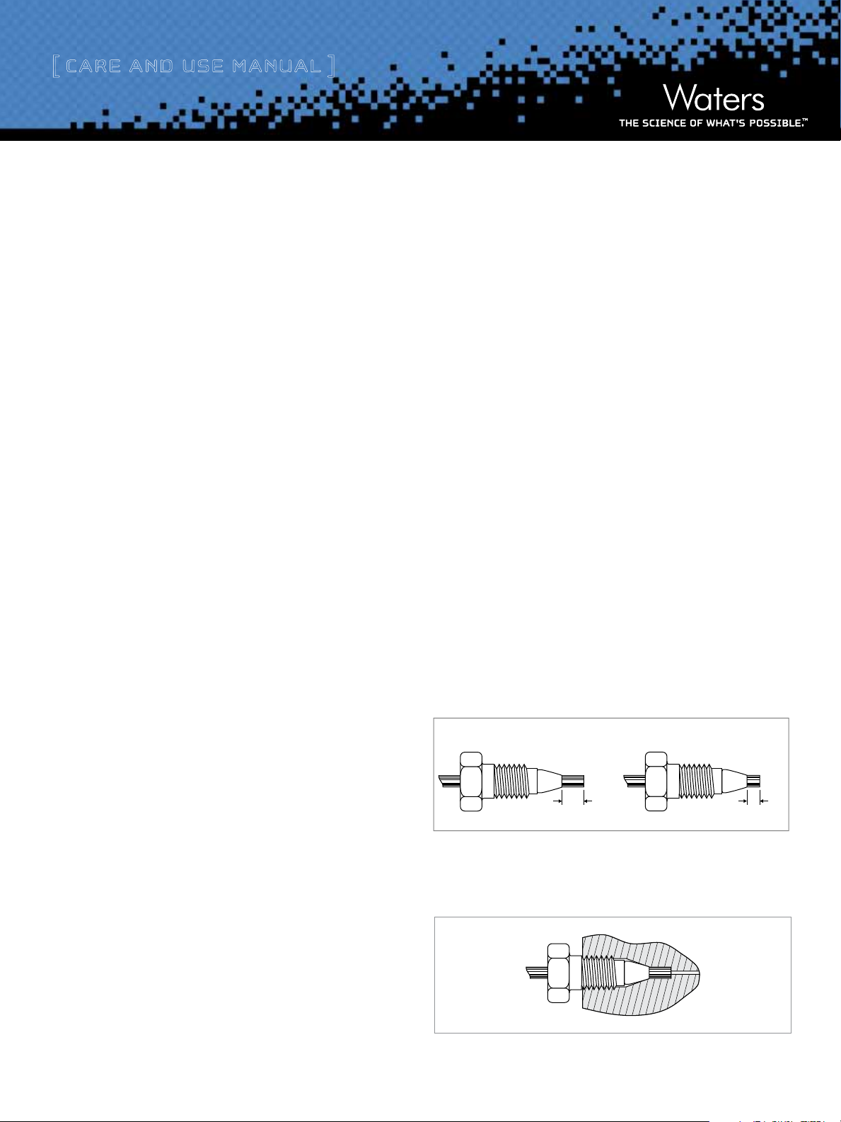
explains the differences between Waters style and Parker style
ferrules and endfittings (Figure 1). Each endfitting style varies
in the required length of the tubing protruding from the ferrule.
The SunFire column is equipped with Waters style endfittings that
require a 0.130 inch ferrule. If a Parker style column is presently
being used, it is critical that the ferrule depth be reset for optimal
performance prior to installing a SunFire column.
Tools needed for SunFire analytical column:
1/2 inch wrench
9/16 inch wrench
Handle the column with care. Do not drop or hit the column on a hard
surface as it may disturb the bed and affect its performance.
1. Correct connection of 1/16 inch outer diameter stainless steel
tubing leading to and from the column is essential for high quality
chromatographic results.
2. When using standard stainless steel compression screw fittings, it
is important to ensure proper fit of the 1/16 inch outer diameter
stainless steel tubing. When tightening or loosening the compression
screw, place a 5/16 inch wrench on the compression screw and a
1/2 inch wrench on the hex head of the column endfitting.
Waters Ferrule Setting
Figure 1: Waters and Parker Style Ferrule Types
In a proper tubing/column connection (Figure 2), the tubing touches
the bottom of the column endfitting, with no void between them.
Figure 2: Proper Tubing/Column Connection
6
Parker Ferrule Setting
.090”.130”
Page 7
[ Care and Use ManUal ]
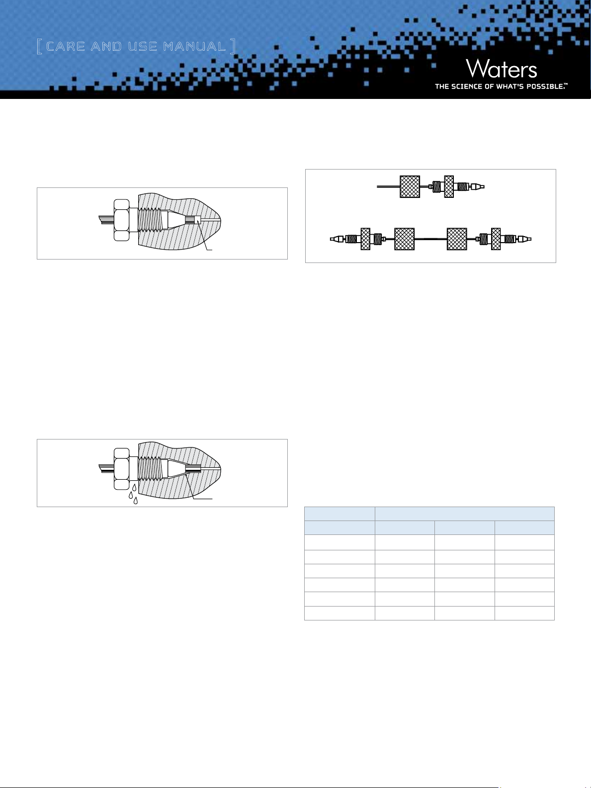
The presence of a void in the flow stream reduces column performance.
This can occur if a Parker style ferrule is connected to a Waters endfitting
(Figure 3).
Void
Figure 3: Parker Ferrule in a Waters Style Endfitting
Note: A void appears if tubing with a Parker style ferrule is connected
to a Waters style column.
There is only one way to fix this problem: Cut the end of the tubing with
the ferrule, place a new ferrule on the tubing and make a new connection.
Before tightening the screw, make sure that the tubing bottoms out in
the endfitting of the column. Conversely, if tubing with a Waters ferrule
is connected to a column with Parker style endfitting, the end of the
tubing will bottom out before the ferrule reaches its proper sealing
position. This will leave a gap and create a leak (Figure 4).
The fingertight SLIPFREE connectors automatically adjust to fit all
compression screw type fittings without the use of tools (Figure 5).
Figure 5: Single and Double SLIPFREE Connectors
SLIPFREE Connectors Features
Tubing pushed into endfitting, thereby guaranteeing
a void-free connection
Connector(s) come(s) installed on tubing
Various tubing i.d. and lengths available
Fingertight to 10,000 psi – never needs wrenches
Readjusts to all column endfittings
Gap
Figure 4: Waters Ferrule in a Parker Style Endfitting
Note: The connection leaks if a Waters ferrule is connected to a
column with a Parker style endfitting.
There are two ways to fix the problem:
1. Tighten the screw a bit more. The ferrule moves forward, and
reaches the sealing surface. Do not overtighten since this may
end in breaking the screw.
2. Cut the tubing, replace the ferrule and make a new connection.
Alternatively, replace the conventional compression screw
®
fitting with an all-in-one PEEK
fitting (Waters Part Number
PSL613315) that allows resetting of the ferrule depth.
(Note: PEEK fittings are not recommended for normal-phase
applications!) Another approach is to use a Thermo Corporation
®
SLIPFREE
connector to always ensure the correct fit.
Compatible with all commercially available endfittings
Unique design separates tube-holding function
from sealing function
Table 4. Waters Part Numbers for SLIPFREE Connectors
SLIPFREE® Type Tubing Internal Diameter
Tubing Length 0.005” 0.010” 0.020”
Single 6 cm PSL 618000 PSL 618 006 P SL 618012
Single 10 cm PS L 6180 02 PSL 618008 PSL 618014
Single 20 cm PS L 618004 PSL 618010 PSL 618 016
Double 6 cm PSL 618001 PSL 618007 PS L 618013
Double 10 cm PSL 618 003 PSL 618009 P SL 618 015
Double 20 cm PSL 618 005 PS L 618001 P SL 618 017
7
Page 8
[ Care and Use ManUal ]
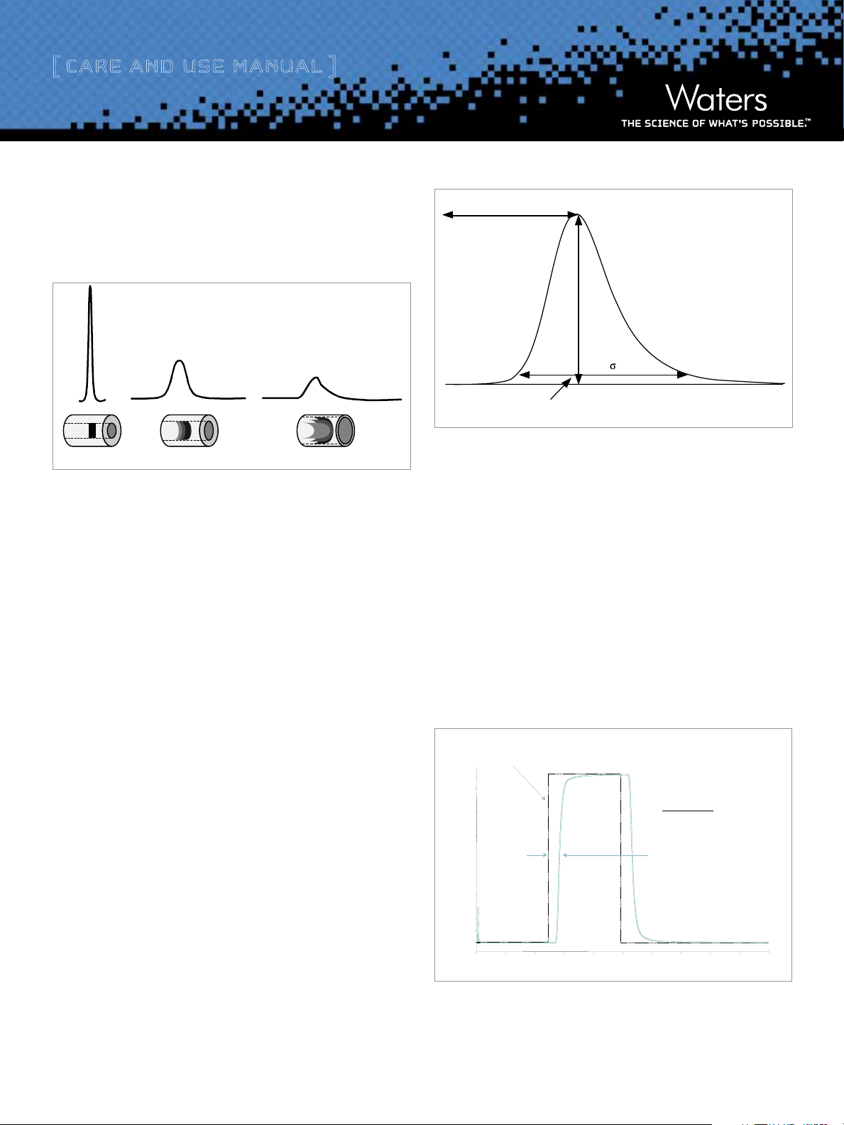
b. Bandspreading Minimization
Figure 6 shows the influence of tubing internal diameter on system
bandspreading and peak shape. As can be seen, the larger tubing
diameter causes excessive peak broadening and lower sensitivity.
0.005 inches
0.020 inches
0.040 inches
Diluted/Distorted Sample Band
Figure 6: Effect of Connecting Tubing on System
c. Measuring System Bandspreading Volume and System
Variance
This test should be performed on an HPLC system with a single
wavelength UV detector (not a Photodiode Array [PDA]).
System Volume
5
4.4 %h
Figure 8: Determination of System Bandspreading Volume Using
5-Sigma Method
In a typical HPLC system, the Bandspreading Volume should be 100 μL ±
2
30 μL (or Variance of 400 μL
+/- 36 μL2). In a microbore (2.1 mm i.d.)
system, the Bandspreading Volume should be no greater than 20 to
2
40 μL (or Variance no greater than 16 μL
to 64 μL2).
d. Measuring System Volume
1. Disconnect column from system and replace with a zero dead
volume union.
2. Set flow rate to 1 mL/min.
3. Dilute a test mix in mobile phase to give a detector sensitivity
of 0.5 - 1.0 AUFS (system start up test mix can be used which
contains uracil, ethyl and propyl parabens; Waters Part Number
WAT034544).
4. Inject 2 to 5 μL of this solution.
5. Measure the peak width at 4.4% of peak height
(5-sigma method):
5-sigma Bandspreading (μL) = Peak Width (min) x Flow Rate (mL/min) x (1000 μL/1 mL)
System Variance (μL2) = (5-sigma bandspreading)h/ 25
System volume is important in scaling separations because it creates an
isocratic hold at the start of every run. This hold is often several column
volumes on a small scale, but a fraction of the volume of a prep column.
Compensation for this volume must be included in planning a scaling
experiment to avoid distorting the chromatography (Figure 9).
Programmed time = 5.00 minutes
0.70
0.65
0.60
0.55
0.50
0.45
0.40
AU
0.35
0.30
0.25
0.20
0.15
0.10
0.05
0.00
50%
0 2 4 6 8 10 12 14 16 18 20 min
Flow Rate = 1.5 mL/min
5.69 minutes
- 5.00 minutes
0.69 minutes
Time = 5.69 minutes
System Volume:
0.69 min x 1.5 mL/min = 1.04 mL
Figure 9: Determination of Gradient Delay Volume
8
Page 9

[ Care and Use ManUal ]
1. Remove column.
2. Use acetonitrile as mobile phase A, and acetonitrile with 0.05
mg/mL uracil as mobile phase B (eliminates non-additive mixing
and viscosity problems).
3. Set UV detector at 254 nm.
4. Use the flow rate in the original method and the intended flow
rate on the target instrument.
5. Collect 100% A baseline for 5 minutes.
6. Program a step change at 5 minutes to 100% B, and collect data
for an additional 5 minutes.
7. Measure absorbance difference between 100% A
and 100% B.
8. Measure time at 50% of that absorbance difference.
9. Calculate time difference between start of step
and 50% point.
10. Multiply time difference by flow rate.
b. Impact of Bandspreading Volume on 2.1 mm i.d.
Column Performance
Note: Flow splitters after the column will introduce additional
bandspreading.
System optimization, especially in a system that contains a flow
splitter, can have dramatic effects on sensitivity and resolution.
Optimization includes using correct-depth ferrules and minimizing
tubing diameter and lengths. An example is given in Figure 10
where system optimization resulted in a doubling of sensitivity and
resolution of the metabolite in an LC/MS/MS system.
7.00 7.50
Non-optimized LC/MS/MS System Optimized System
8.00
7.00 7.50 8.00
VII. ADDITIONAL INFORMATION
a. Use of Narrow-bore (<3.0 mm i.d.) Columns
This section describes how to minimize extra column effects
and provides guidelines on maximizing the performance of
a narrow-bore column in an HPLC system. A 3.0 mm i.d.
narrow-bore column usually requires no system modifications.
A 2.1 mm i.d. column, however, requires modifications to
the HPLC system in order to eliminate excessive system
bandspreading volume. Without proper system modifications,
excessive system bandspreading volume causes peak broadening and
has a large impact on peak width as peak volume decreases.
Figure 10: Non-Optimized vs. Optimized LC/MS/MS System
c. Non-Optimized vs. Optimized LC/MS/MS System: System Modification Recommendations
1. Use a microbore detector flow cell with ≤2.1 mm i.d. columns.
Note: Detector sensitivity is reduced with the shorter flow cell
path length in order to achieve lower bandspreading volume.
2. Minimize injector sample loop volume.
3. Use 0.009 inch (0.25 mm) tubing between pump
and injector.
4. Use 0.009 inch (0.25 mm) tubing for rest of connections
in standard systems and 0.005 inch (0.12 mm) tubing for
narrowbore (2.1 mm i.d.) systems.
5. Use perfect (pre-cut) connections (with a variable depth inlet if
using columns from different suppliers).
6. Detector time constants should be shortened to less than
0.2 seconds.
9
Page 10

[ Care and Use ManUal ]
Sales Offices
Austria and European Export
(Central South Eastern Europe, CIS
and Middle East) 43 1 877 18 07
Australia 61 2 9933 1777
Belgium 32 2 726 1000
Brazil 55 11 5094-3788
Canada 1 800 252 4752 x2205
China 86 21 6879 5888
CIS/Russia +497 727 4490/290 9737
Czech Republic 420 2 617 1 1384
Denmark 45 46 59 8080
Finland 09 5659 6288
France 33 1 30 48 72 00
Germany 49 6196 400600
Hong Kong 852 2964 1800
The Netherlands 31 76 508 7200
Norway 47 6 384 60 50
Poland 48 22 6393000
Puerto Rico 1 787 747 8445
Singapore 86 21 6879 5888
Spain 34 936 009 300
Sweden 46 8 555 11 500
Switzerland 41 56 676 70 00
Taiwan 886 2 2543 1898
United Kingdom 44 208 238 6100
All other countries:
Waters Corporation U.S.A.
1 508 478 2000
1 800 252 4752
www.waters.com
Hungary 36 1 350 5086
India and India Subcontinent
91 80 2837 1900
Ireland 353 1 448 1500
Italy 39 02 265 0983
Japan 81 3 3471 7191
Korea 82 2 6300 4800
Mexico 52 55 5524 7636
© 2010 Waters Corporation. Waters, The Science of W hat’s Possible,
SunFire, Oasis and SepPak are trademarks of Waters Corporation. Acrodisc is
a trademark of Pall Corporation. PEEK is a trademark of Agilent Technologies.
SLIP FREE is a trademark of T hermo Fisher Scientific Inc.
December 2010 715000891 Rev C KK.PDF
Waters Corporation
34 Maple Street
Milford, MA 01757 U.S.A.
T: 1 508 478 2000
F: 1 508 872 1990
www.waters.com
 Loading...