

Page 1

[ Care and Use ManUal ]
Waters Pah Column
I. IntroduCtIon
We are sure you will find that Waters built-in quality helps solve many of
your challenging separation problems. We strive to provide products with the
highest degree of lot-to-lot and column-to-column reproducibility to mini-
mize variations in your chromatographic results. Waters PAH columns are
manufactured and packed under highly controlled conditions. Each must pass
a series of stringent tests before being accepted for shipment. Included with
each column is the final Certificate of Analysis.
Polynuclear Aromatic Hydrocarbons (PAHs) are among the most frequently
monitored environmental contaminants. Standard and official methods for the
analysis of PAHs are found in compendia for air, drinking water, wastewater,
solid waste, and food analysis1.
Many of these methods specify HPLC, usually with UV and fluorescence detec-
tion, as the recommended analytical procedure.
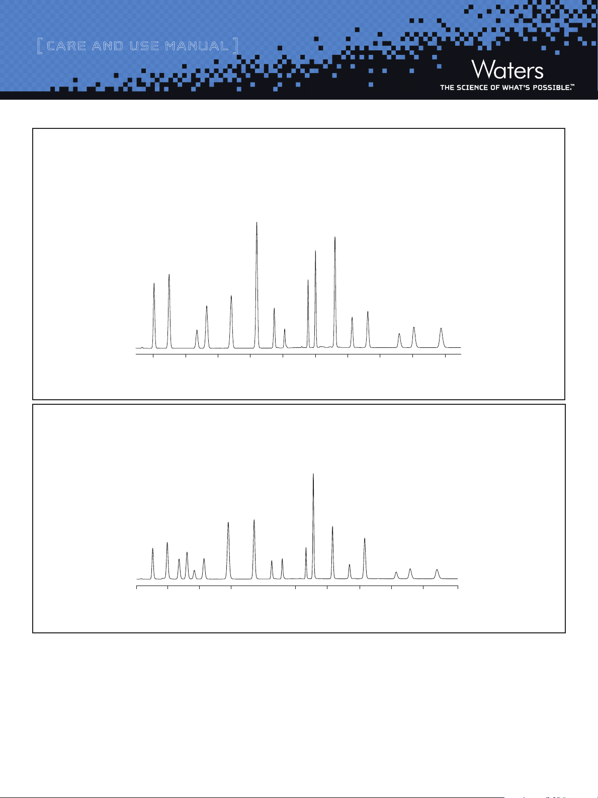
Waters PAH columns are optimized for the HPLC analysis of PAHs. Figure 1
shows a chromatogram of 16 PAH compounds, listed as target pollutants by
the U.S. EPA. The Waters PAH columns achieve baseline resolution and excel-
lent peak symmetry for all 16 target analytes in less than 25 minutes, while
employing a simple water; acetonitrile binary gradient. The resolving power
of the PAH Columns provides superior peak identification and quantitation
for PAHs.
Florida Administrative Code 17.700 includes 2 additional compounds
(1-methyl naphthalene and 2-methyl naphthalene ) in addition to the 16 com-
pound EPA 610 mix that we currently use to show the proficiency of Waters
instrumentation to analyze PAH compounds. The new Waters PAH columns
resolve these two compounds along with the other 16, (see Figure 2).
Contents
I. IntroduCtIon
II. ConneCt Ing the Column to the hP lC Inst rument
a. Column Connectors and System Tubing Considerations
b. SLIPFREE Connectors
c. Minimization of Band Spreading
d. Measuring System Bandspread Volume
e. Measuring Gradient Delay Volume
f. Use of Narrow-Bore Columns (3.0 mm i.d.)
g. Impact of bandspreading on Column performance
(2.1 mm i.d. column)
h. System Modification Guidelines
III. Column equIlIbratIon
IV. Column usage
V. Column CleanIng, regeneratIng and storage
a. Cleaning and Regeneration
b. Storage
VI. t roubleshootIng
Name of Document 1
Page 2
[ Care and Use ManUal ]
Minutes
246810 12 14 16 18 20 22
1
2
3
4
5
6
7
8
9
10
11
12
13
14
15
16
9 11 13 15 17 19 21 23 25
1
2
3 *
4 *
5
6
7
8
9
10
11
12
13
14
15
16
17
18
Minutes
57
Column: Waters PAH Column 5 μm 4.6 x 250 mm @ 27 °C Peaks:
System: Waters Alliance System with 2996 Photodiode Array Detector
Eluent A: Water
Eluent B: Acetonitrile
Gradient: 60% B to 100% B using curve 9 in 12 minutes,
hold 11 minutes, back to initial conditions
Flow Rate: 1.2 mL/min
Injection: 20 μL
Sample: EPA-610 mixture
UV @ 254 nm
Figure 1: PAH Analysis using Waters PAH Columns
Column: Waters PAH Column 5 μm 4.6 x 250 mm @ 27 °C Peaks:
Eluent A: Water
Eluent B: Acetonitrile
Gradient: 60% B to 100% B using curve 9 in 12 minutes
hold 11 minutes, back to initial conditions
Flow Rate: 1.2 mL/min
Injection: 20 μL
Sample: EPA-610 mixture plus two compounds*
1. Naphthalene - 20 ppm
2. Acenaphthylene - 40 ppm
3. Acenaphthene - 20 ppm
4. Fluorene - 4 ppm
5. Phenanthrene - 2 ppm
6. Anthracene - 2 ppm
7. Fluoranthene - 4 ppm
8. Pyrene - 2 ppm
1. Naphthalene - 20 ppm
2. Acenaphthylene - 40 ppm
3*. 1-methyl naphthalene - 25 ppm
4*. 2-methyl naphthalene - 25 ppm
5. Acenaphthene - 20 ppm
6. Fluorene - 4 ppm
7. Phenanthrene - 2 ppm
8. Anthracene - 2 ppm
9. Fluoranthene - 4 ppm
9. Benzo(a)anthracene - 2 ppm
10. Chrysene - 2 ppm
11. Benzo(b)fluoranthene - 4 ppm
12. Benzo(k)fluoranthene - 2 ppm
13. Benzo(a)pyrene - 2 ppm
14. Dibenzo(a,h)anthracene - 4 ppm
15. Benzo(g,h,I)perylene - 4 ppm
16. Indeno(1,2,3-cd)pyrene - 2 ppm
10. Pyrene - 2 ppm
11. Benzo(a)anthracene - 2 ppm
12. Chrysene - 4 ppm
13. Benzo(b)fluoranthene - 4 ppm
14. Benzo(k)fluoranthene - 2 ppm
15. Benzo(a)pyrene - 2 ppm
16. Dibenzo(a,h)anthracene - 4 ppm
17. Benzo(g,h,I)perylene - 4 ppm
18. Indeno(1,2,3-cd)pyrene - 2 ppm
UV @ 254 nm
Figure 2: PAH Analysis According to Florida Administrative Code 17,700
II. CONNECTING THE COLUMN TO THE HPLC INSTRUMENT
Handle the column with care. Do not drop or hit column on a hard surface
as it may disturb the bed and affect its performance.
1. Correct connection of 1/16 inch outer diameter stainless steel tubing
leading to and from the column is essential for high-quality chromato-
graphic results.
Name of Document 2
2. When using standard stainless steel compression screw fittings, it is
important to ensure proper fit of the 1/16 inch outer diameter stainless
steel tubing. When tightening or loosening the compression screw, place
the 5/16 inch wrench on the compression screw and the other 3/8 inch
wrench on the hex head of the column endfitting. Note: If one of the
wrenches is placed on the column flat during this process, the endfitting
will be loosened and leak.
Page 3
[ Care and Use ManUal ]
0.090 inches
0.130 inch
e
Gap
Void
3. If a leak occurs between the stainless steel compression screw fitting
and the column endfitting, a new compression screw fitting, tubing and
ferrule must be assembled.
4. An arrow on the column identification label indicates correct direction
of solvent flow.
It is important to realize that extra column peak broadening can destroy suc-
cessful separation. The choice of appropriate column connectors and system
tubing is discussed in detail below.
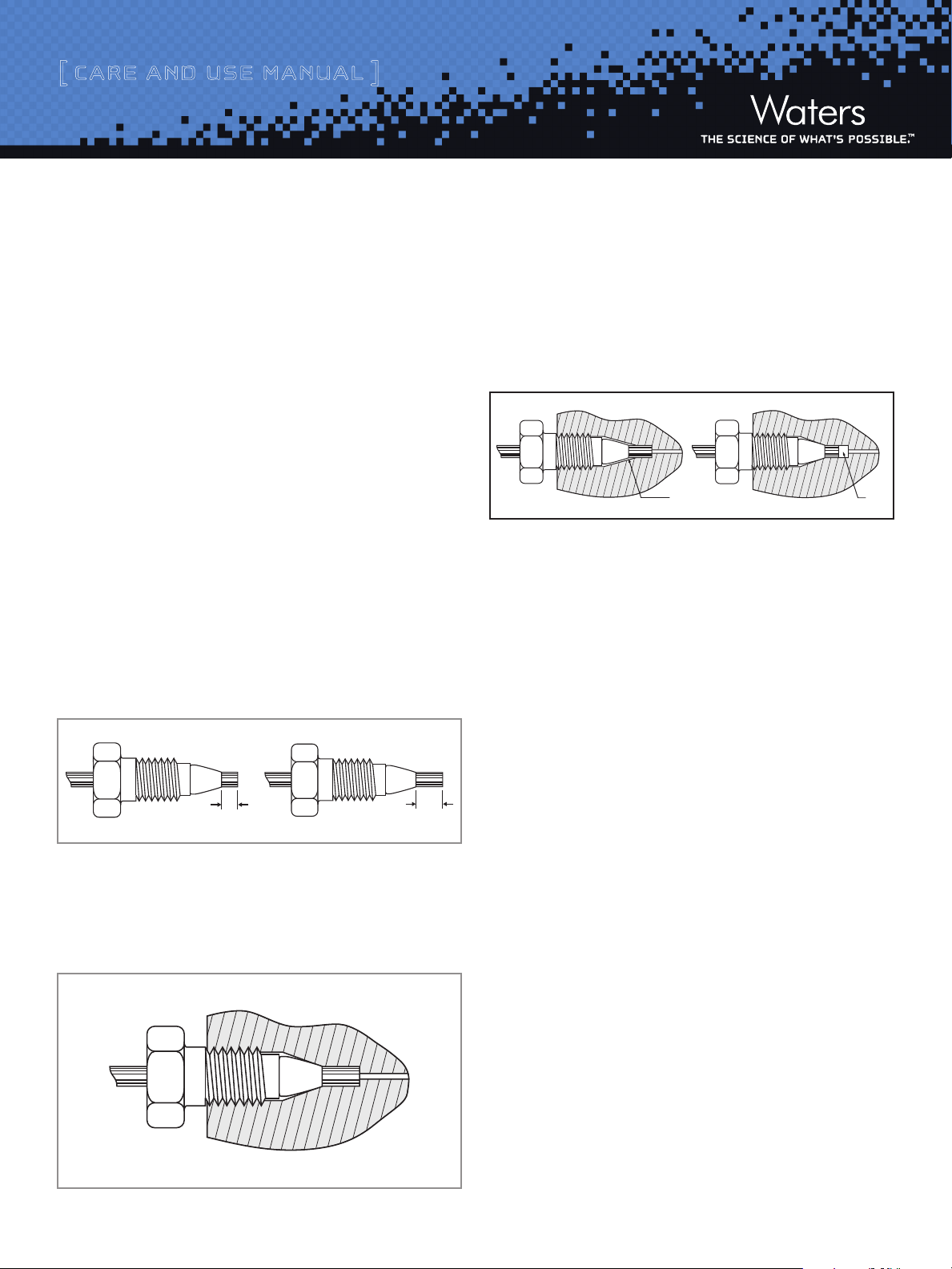
a. Column Connectors and System Tubing Considerations
Due to the absence of an industry standard, various column manufacturers
have employed different styles of chromatographic column connectors. The
chromatographic performance of your separation can be negatively affected if
the style of your column endfittings do not match the existing instrumenta-
tion tubing ferrule setting. This page explains the difference between Waters
style and Parker style endfittings, which vary in the required length of the
tubing protruding from the ferrule. The PAH column is equipped with Waters
style endfittings which require a 0.130 inch ferrule depth (see next section
for setting ferrule depth). If you are presently using a non-Waters style
column, it is critical that you reset the ferrule depth for optimal performance.
A void appears if a tube with Parker ferrule setting is connected to a Waters
style column.
The presence of a void in the flow stream downgrades the column perfor-
mance. There is only one way to fix the problem: Cut the end of the tubing
with the ferrule, put a new ferrule on the tubing and make the connection.
Before tightening the screw, make sure that the tubing bottoms out in the
endfitting of the column.
If tubing with a Waters style ferrule setting is connected to a column with
Parker style endfitting, the end of the tubing will bottom out before the fer-
rule reaches its proper sealing position. This will leave a gap creating a leak.
There are two ways to fix the problem:
1. Just tighten the screw a little bit more. The ferrule moves forward, and
reaches the sealing surface. Do not overtighten because this may end in
breaking the screw.
The Proper Tubing/Column Connection
Tubing touches the bottom of the column endfitting, with no void
between them.
2. Cut the tubing, put a new ferrule on it and make the connection.
An alternative is to replace the conventional compression screw fitting with
an all-in-one PEEKTM fitting.
(Waters part number PSL613315) that allows you to reset the ferrule depth.
Another approach is to use a SLIPFREE® fitting to always ensure the correct
fit. The finger-tight SLIPFREE connectors automatically adjust to fit all
compression screw type fittings without the use of tools.
Name of Document 3
Page 4

[ Care and Use ManUal ]
Diluted/Distorted Sample Band
0.005 inches
0.020 inches
0.040 inches
b. SLIPFREE Connectors
Guarantees a void-free connection because it pushes the tubing into the
endfitting; This design comes installed on the tubing. Fingertight to
10,000 psi – never needs wrenches. Readjusts to all column endfit-
tings. Compatible with all commercially available endfittings. Unique
design separates tube-holding function from sealing function.
c. Minimization of Bandspreading
The following figure shows the influence of tubing internal diameter on
system band spreading and peak shape. As can be seen, the larger tubing
diameter causes excessive peak broadening and lower sensitivity.
3. Dilute a test mix in mobile phase to give a detector sensitivity 0.5-1.0
AUFS (can use the system start up test mix which contains uracil, ethyl
and propyl parabens; Waters part number WAT034544).
4. Inject 2 to 5 mL of this solution.
In a typical LC bandspreading volume system should be 100 mL ±
30 mL (or variance of 400 μL2 +/- 36 μL2)
Microbore (2.1 mm i.d. and smaller) system should be no greater than
20-40 mL
Figure 4: Determination of System Bandspread Volume using the
5-Sigma Method
Figure 3: Effect of Connecting Tubing on System
d. Measuring System Bandspread Volume
1. Disconnect column from system and replace with a zero dead volume
union.
2. Flow rate 1 mL/min. This should be performed on a single wavelength
detector (not a PDA/DAD).
e. Measuring Gradient Delay Volume
1. Replace the column with a zero dead volume union.
2. Determine the gradient-delay or dwell volume for your system by
performing the following test. Prepare eluent A (pure solvent, such
as methanol) and eluent B (solvent plus sample, such as 5.6 mg/mL
propylparaben in methanol).
3. Equilibrate the system with eluent A until a stable baseline is achieved.
Switch to 100% eluent B and record the half height of the step. Refer to
Figure 5 for an illustration.
The dwell volume should be less than 1 mL. If this is not the case, see section
on System Modifications (below) to reduce your system volume.
Name of Document 4
Page 5

[ Care and Use ManUal ]
Volum e (µL)
Dwell
Volum e
1.0
0.8
0.6
0.4
Height
0.2
0.0
7.00 7.50
Non-optimized LC/MS/MS System Optimized System
8.00
7.00 7.50 8.00
Optimizing a system, especially one using flow splitters can have a dramatic
effect on sensitivity andresolution. Use of correct ferrule depth connectors
and minimizing tubing diameter and lengths showed a doubling of sensitivity
and enabled resolution of the metabolite on this LC/MS/MS system.
h. System Modification Guidelines
1. Use a microbore detector flow cell with the 2.1 mm columns. Recall
that due to the shorter pathlength, detector sensitivity is reduced to
achieve lower band spread volume.
2. Injector sample loop should be reduced to minimum.
Figure 5: Determination of Dwell Volume
f. Use of Narrow-Bore Columns – (3.0 mm i.d.)
This section describes how to minimize extra column effects and gives some
guidelines on how to maximize the advantages of your narrow-bore column.
The 3.0 mm i.d. narrow-bore column usually requires no system modifica-
tions. With the 2.1 mm i.d. column, however, modifications to your HPLC
system may be required in order to eliminate excessive system bandspread
volume. Without proper system modifications, excessive system bandspread
volume causes peak broadening and has a large impact on peak width as peak
volume decreases.
g. Impact of Bandspreading on Column Performance
(2.1 mm i.d. column)
System with 70 mL bandspread >> 10,000 plates
System with 130 mL bandspread >> ~8,000 plates (same column)
Note: Flow splitters after the column will introduce additional bandspreading.
3. Use 0.009 inch (0.25 mm) tubing between pump and injector.
4. Use 0.009 inch (0.25 mm) tubing for rest of connections in
standardsystems and 0.005 inch (0.12 mm) tubing for narrowbore
(2.1 mm i.d.) systems.
5. Use perfect (pre-cut) connections (with a variable depth inlet if using
columns from different suppliers).
6. Time constants should be shortened <0.2 Column Equilibration.
III. COLUMN EqUILIBRATION
Waters delivers the column in 100% acetonitrile. It is important to ensure
solvent compatibility before changing to a new solvent. Equilibrate your
column with a minimum of 10 times its internal volume with the mobile
phase to be used (refer to Table 1 for some standard column volumes).
1. Purge your pumping system and then connect the inlet end of the
column to the injector outlet. Turn on the pump flow at 0.1 mL/min.
and increase to 1 mL/min over 5 minutes.
Figure 6: Impact of Bandspreading
Name of Document 5
2. When the solvent is flowing freely from the column outlet, attach the
column to the detector. This procedure prevents entry of air into the
detection system and gives more rapid equilibration.
3. When the mobile phase is changed, gradually increase the flow rate of
the new mobile phase from zero mL/min to 1.0 mL/min in 0.1 mL/min
increments.
4. Once a steady backpressure and baseline have been achieved, the
column is ready to be used.
Page 6

[ Care and Use ManUal ]
Note: If mobile phase additives are present in low concentrations (such as
ion-pairing reagents, at 5 to 10 mmol/L) 100 to 200 column volumes may
be required for complete equilibration.
Table 1. Volume of Standard Column (mL), Multiply by 10 for Flush
Solvent Volume
Column Internal Diameter (mm)
Column Length
50 mm 0.2 0.3 0.8
100 mm 0.4 0.7 1.7
150 mm 0.5 1.0 2.5
250 mm 0.9 1.8 4
2.1 3.0 4.6
IV. COLUMN USAGE
To ensure the continued high performance of your columns and cartridges,
follow these guidelines:
a. Guard Columns
c. Solvents
To maintain maximum column performance, use high quality chromatography
grade solvents. Filter all buffers before use. Pall Gelman Laboratory Acro-
disc® filters are recommended. Solvents containing suspended particulate
materials will generally clog the outside surface of the inlet distribution frit
of the column. This will result in higher operating pressure and poorer perfor-
mance. Degas all solvents thoroughly before use to prevent bubble formation
in the pump and detector.
d. Pressure
All Waters PAH columns, regardless of dimension, can be operated at pres-
sures up to 6000 psi, 400 bar or 40 Mpa.
e. Temperature
Temperatures between 20 – 50 °C are recommended for operating Waters
PAH columns to enhance selectivity, lower solvent viscosity and increase
mass transfer rates. However, any temperature rise above ambient will have
a negative effect on lifetime which will vary depending on the pH and buffer
conditions used.
Sample impurities very often contribute to column contamination.
Two ways to avoid this are:
a. Use of Waters Oasis® solid-phase extraction sample clean-up car-
tridges or columns or Sep-Pak® cartridges of the appropriate chemistry
to clean up your sample before analysis.
b. Use of a Waters guard cartridge of matching chemistry and particle
size between the injector and main column. It is important to use a
highperformance matching guard column to protect the main column
while not compromising analytical resolution.
b. pH Range
Recommended pH ranges for solvent and buffer combinations for Waters PAH
columns are between 2.0 and 8.0. A pH less than 2 may cause hydrolysis of
the bonded phase. At a pH greater than 7.0, the alkaline solvent buffers will
attack the silica substrate resulting in void formation in the column as the
silica solubilizes.
V. COLUMN CLEANING, REGENERATING AND STORAGE
a. Cleaning and Regeneration
A shift in retention or resolution may indicate contamination of the column
Flushing with a neat organic solvent is usually sufficient to remove the
contaminant. If the flushing procedure does not solve the problem, purge
the column with a sequence of progressively more nonpolar or hydrophobic
solvents. For example, switch from water to tetrahydrofuran (THF) to meth-
ylene chloride. Return to the standard mobile phase conditions by reversing
the sequence. Guard columns need to be replaced at regular intervals as
determined by sample contamination. When system backpressure steadily
increases above a set pressure limit, it is usually an indication that the guard
column should be replaced.
b. Storage
For periods longer than four days store the column in 100% acetonitrile.
Do not store columns in buffered, acidic or basic eluents. If the mobile phase
contained a buffer salt flush the column with 10 column volumes of HPLC
grade water (see Table 1) and replace with 100% acetonitrile. Completely
seal column to avoid evaporation and drying out of the bed.
Name of Document 6
Page 7

[ Care and Use ManUal ]
VI. TROUBLESHOOTING
Changes in retention time, resolution, or backpressure are often due to
column contamination. See the Column Cleaning, Regeneration and Storage
section of this instruction sheet. Information on colum troubleshooting
problems may be found in HPLC Columns Theory Technology and Practice,
U.D. Neue, (Wiley-VCH, 1997) or the Waters HPLC Troubleshooting Guide
(Literature code # 720000181EN).
Sales Offices:
Austria and European Export
(Central South Eastern Europe,
CIS and Middle East) 431 877 18 07
Australia 2 9933 1777
Belgium 32 2 726 1000
Brazil 55 11 5094 3788
Canada 800 252 4752
China 8621 6495 6999
CIS/Russia +7 495 3367000
Czech Republic 42 02 617 11384
Denmark 45 46 59 8080
Finland +358 9 5659 6288
France (33) 1 30 48 72 00
Germany 49 6196 400600
Hong Kong 852 29 64 1800
Hungary 36 1 350 5086
India and India Subcontinent
91 80 2 837 1900
Ireland 353 1 448 1500
Italy 39 02 274 211
Japan (81) 3 3471 7191
Korea (82) 2 820 2700
Mexico 5255 5200 1860
The Netherlands +31 (0)76-50 87 200
Norway 47 63 84 60 50
Poland (48) 22 833 4400
Puerto Rico 787 747 8445
Singapore 65 6273 1221
Spain 34 93 600 93 00
Sweden 46 8 555 11500
Switzerland 41 62 889 2030
Taiwan 886 2 2543 1898
©2008 Waters Corporation, Waters. Oasis, Sep-Pak
and The Science of What’s Possible are trademarks
of Waters Corporation. SLIPFREE is a trademark of
Thermo Scientic. Acrodisc is a trademark of Pall
Gelman Laboratory.
May 2008 735000506 Rev 3 VW-PDF
Name of Document 7
United Kingdom 44 208 238 6100
Waters Corporation
34 Maple Street
Milford, MA 01757 U.S.A.
T: 1 508 478 2000
F: 1 508 872 1990
www.waters.com
 Loading...