

Page 1
[ Care and Use ManUal ]
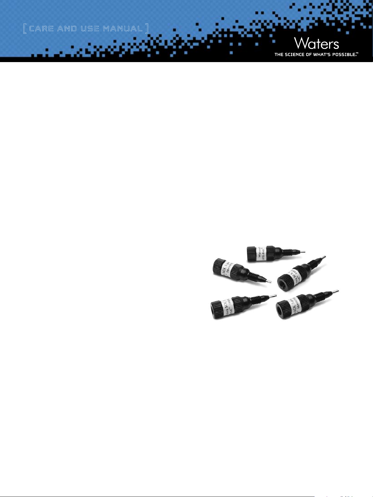
nanoEasE trappinG columns
i. introduction:
Waters NanoEase Trapping Columns are robust devices that can effectively
separate complex samples and remove buffers and high concentrations of
salts. For the latest on Life Science Chemistries, go to:
www.waters.com/lifesciences.
ii. nanoEasE trap column prEparation
1. It is recommended that the trap column be washed and conditioned
with a suitable solvent before use. This can be accomplished using
a suitable syringe to flush solvent through the column. If a syringe
is used for this purpose, it is recommended that a syringe with an
inert teflon plunger and glass body be used to avoid contami-
nation. Syringes with rubber plungers or plastic bodies should
not be used. Alternatively, the trap column can be placed on the
HPLC system and washed with suitable solvent at a flow rate of
10-40 µL/min for several minutes prior to use.
®
2. If using a 10-port valve, use UpChurch
part # F-285X) in eac h adjacent port of the 10-port valve, due to
the clearance width of the trap column.
long nuts (UpChurch
contEnts
i. introduction
ii. nanoEasE trap column prEparation
iii. GEnEral GuidElinEs for column usE
iv. ordErinG information
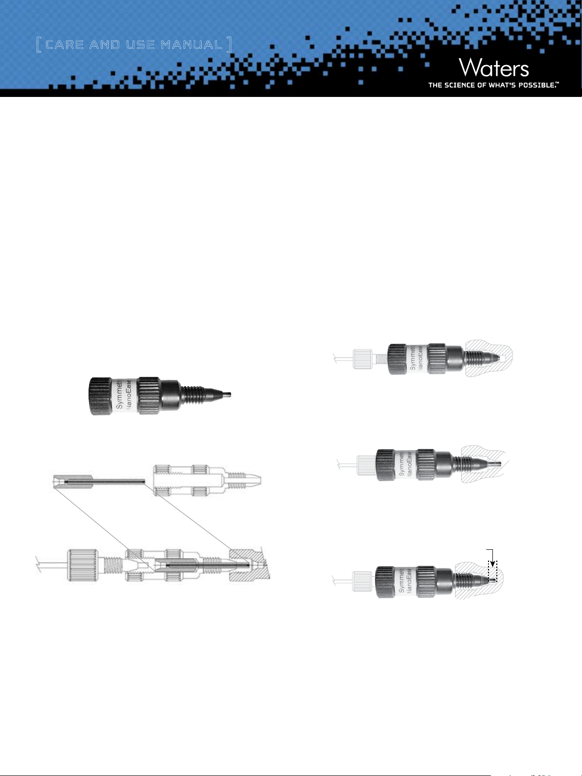
3. The trap column works with the black 10-32 outer fitting with
white label (Figures 1a and 1b), which secures the stainless steel
®
tu be and the tan P EEK
switching valve.
NanoEase Trapping Columns 1
(column insert part) pie ce ( Figure 2) to the
Page 2
[ Care and Use ManUal ]
4. To secure the column into a multi-port valve, care must be taken
to get the face of the stainless steel barrel seated properly into
the port without introducing dead volume between the frit at the
end of the stainless steel barrel and the valve port. The stainless
steel barrel must not protrude too far past the end of the black
fitting, otherwise there will not be enough threads of the fitting
protruding into the valve port to make a proper seal. Consult Fig-
ures to see how to properly seal the trap into the valve port and
connect the desired tubing. The following steps are suggested:
a) First make sure that the trap column insert (Figure 2) is
inside the black fitting (Figure 1b).
b) Screw in a column-blanking plug into the top of the black
fitting (Figure 3) until the stainless steel barrel protrudes
from the end of the fitting approximately between 2 and 3
mm (Figure C). It may be necessary to use your finger (use
a glove to avoid contamination of the trap) to push against
the end of the stainless steel barrel so that the other end of
the insert is set against the column-blanking plug and the
stainless steel barrel protrudes from the end of the black
fitting at the proper depth. Adjust the position of the col-
umn-blanking plug if necessary.
a. Illustration of adjusting the length of the stainless
steel barrel
Figure A. Incorrect. Results in dead volume between valve port and trap column
Figure 1a
Figure 3
Figure 2
Figure 1b
Figure B. Incorrect. Note these are insufficient number of threads to seal trap
column to valve
2-3 mm
Figure C. Correct.
NanoEase Trapping Columns 2
Page 3

[ Care and Use ManUal ]
NanoEase
trap column
25 mm i.d. fused silica tubing
to nanoLC
column
3
1
10
9
8
7
6
5
4
2
waste
10-Port
Va lve
auxiliary
pump
A/S
valve
nanoLC gradient
10-32 fitting with
fused silica sleeve
25 mm i.d. fused silica tubing
to nanoLC
column
3
1
10
9
8
7
6
5
4
2
waste
10-Port
Va lve
auxiliary
pump
A/S
valve
nanoLC gradient
10-32 fitting with
fused silica sleeve
NanoEase
trap column
c) Grip the outside of black fitting (Figure 1a and 1b) and care-
fully screw it into the valve port to seal the trap into the
valve, while being careful not to rotate the column-blanking
plug.
d) Check to see that the black fitting is tightly sealed into the
valve, but do not overtighten it.
e) Secure the tubing to form the “sample loop” (fused silica, or
60 mm i.d. tan PEEK) into the top of the trap column with an
appropriate fitting (see Figure 3).
5. For Nano LC applications using 75 μm analytical columns, dead
volume can be minimized when using a multi-port valve by
placing the trap column at the closest end to the inlet of the
analytical column. Figures 4 and 5 show the plumbing diagram of
such a configuration for the wash and elute cycles using a 10-port
switching valve.
6. Connect up the HPLC System and start flow through the
NanoEase Trap Column. Check for leaks and tighten the fittings
if necessary.
iii. GEnEral GuidElinEs for column usE
Typical Separation Flow Rates: 1-40 µL/min
®
Typical Loading Flow Rate: 15 µL/min for 4 minutes (with Waters CapL
Stream Select Module)
Loading Capacity: 2-5 µg maximum for the RP; 4-8 µg maximum for the SCX
(will vary depending on sample)
Storage Recommendations: Long term storage in acetronitrile for the RP;
Storage in aqueous solvent is adequate for SCX (e.g. HPLC grade water with
acetronitrile).
Typical Column Lifetime: Varies depending on sample and care of column,
but excess of 100 injections is possible.
and
Figure 4. Loading and wash step Figure 5. Elution step
NanoEase Trapping Columns 3
Page 4

[ Care and Use ManUal ]
iv. ordErinG information
Description Particle Size Dimension Part No.
Symmetry300
Atlantis
SCX 300
Symmetry
0.18 i.d. Custom Trap Column 5/pack Custom 0.18 x 23.5 mm 186002687
0.50 i.d. Custom Trap Column 5/pack Custom 0.50 x 23.5 mm 186002806
Sales Offices:
™
C18 Trap Column 5/pack 5 μm 0.18 x 23.5 mm 186002622
®
dC18 Trap Column 5/pack 5 μm 0.18 x 23.5 mm 186002574
®
Trap Column 5/pack 5 μm 0.50 x 23.5 mm 186002623
®
C18 Trap Column 5/pack 5 μm 0.18 x 23.5 mm 186002808
Austria and European Export
(Central South Eastern Europe,
CIS and Middle East) 431 877 18 07
Australia 2 9933 1777
Belgium 32 2 726 1000
Brazil 55 11 5094 3788
Canada 800 252 4752
China 8621 6495 6999
CIS/Russia +7 495 3367000
Czech Republic 42 02 617 11384
Denmark 45 46 59 8080
Finland +358 9 5659 6288
France (33) 1 30 48 72 00
Germany 49 6196 400600
Hong Kong 852 29 64 1800
Hungary 36 1 350 5086
India and India Subcontinent
91 80 2 837 1900
Ireland 353 1 448 1500
Italy 39 02 274 211
Japan (81) 3 3471 7191
Korea (82) 2 820 2700
Mexico 5255 5200 1860
The Netherlands +31 (0)76-50 87 200
Norway 47 63 84 60 50
Poland (48) 22 833 4400
Puerto Rico 787 747 8445
Singapore 65 6273 1221
Spain 34 93 600 93 00
Sweden 46 8 555 11500
Switzerland 41 62 889 2030
Taiwan 886 2 2543 1898
United Kingdom 44 208 238 6100
©2007 Waters Corporation, Waters, The Science of W hat’s Possible, CapLC, Symmetry, Atlantis, Symmetry300, SCX 300 and
NanoEASE are trademarks of Waters Corporation. UpC hurch is a
trademark of Upc hurch Scientific®, a Unit of IDEX® Corporation. PEEK is a trademark of Victrex plc.
Printed in the U.S.A. 11/2007 715001556 Rev B VW-P DF
Nanoease Trapping Columns 4
Waters Corporation
34 Maple Street
Milford, MA 01757 U.S.A.
T: 1 508 478 2000
F: 1 508 872 1990
www.waters.com
 Loading...