

Page 1

W a ters Micromass
ZQ Detector
Operator’s Guide
34 Maple Street
Milford, MA 01757
71500044702, Revision B
Page 2

NOTICE
The information in this document is subject to change without notice and should not be
construed as a commitment by Waters Corporation. Waters Corporation assumes no
responsibility for any errors that may appear in this document. This document is believed
to be complete and a c cu rate at th e time o f p u blication. In no event shall Water s
Corporation be liable for incidental or consequential damages in connec tion with, or
arising from, the use of this document.
© 2002 WATERS CORPORATION. PRINTED IN THE UNITED STATES OF AMERICA.
ALL RIGHTS RESERVED. THIS D OCUMENT OR PARTS THEREOF MAY NOT BE
REPRODUCED IN ANY FORM WITHOUT THE WRITTEN PERMISSION OF THE
PUBLISHER.
Alliance, Micromass, and Waters are registered trademarks, and Empower, ESCi,
MassLynx, and SAT/IN are trademarks of Waters Corporation.
Microsoft, Windows, and Windows NT are registered trademarks of Microsoft Corporation.
All other trademarks or registered trademarks are the sole property of their respective
owners.
Page 3

When you use the instrument, follow generally accepted procedures for quality
Note:
control and methods development.
If you observe a change in the retention of a particular compound, in the resolution
between two compounds, or in peak shape, immediately determine the reason for the
changes. Until you determine the cause of a change, do not rely on the separation results.
The Installation Category (Overvoltage Category) for this instrument is Level II. The
Note:
Level II Category pertains to equipment that receives its electrical power from a local level,
such as an electrical wall outlet.
STOP
Atención:
responsible for compliance could void the user’s authority to operate the equipment.
Importan t :
par l’autorité responsable de la conformité à la réglementation peut annuler le droit de
l’utilisateur à exploiter l’équi pem ent .
Achtun g :
ausdrückliche Genehmigung der für die ordnungsgemäße Fun ktion stüchtigkeit
verantwortlichen Personen kann zum Entzug der Bedienungsbefugnis des Systems
führen.
Avvertenza:
espressamente approvate da un ente responsabile per la conformità annulleranno
l’autorità dell’utente ad operare l’apparecchiatura.
Atención:
expresamente aprobado por la parte responsable del cumplimiento puede anular la
autorización del usuario para utilizar el equip o.
Changes or modifications to this unit not expressly approved by the party
Toute modification sur cette unité n’ayant pas été expressément approuvée
Jedwede Änderungen oder Modifikationen an dem Gerät ohne die
eventuali modifiche o alterazioni apportate a questa unità e non
cualquier cambio o modificación efectuado en esta unidad que no haya sido
Page 4

Caution:
Use caution when working with any polymer tubing under pressure:
• Always wear eye protection when near pressurized polymer tubing.
• Extinguish all nearby flames.
• Do not use Tef zel tubing tha t has been severely stressed or kinked.
• Do not use Tefz el tubing with tetrahydrofuran (THF) or concentrated nitric or
sulfuric acids.
• Be aware that methylene chloride and dimethyl sulfoxide cause Tefzel tubing to
swell, which greatly reduces the rupture pressure of the tubing.
Attention :
Soyez très prudent en travaillant avec des tuyaux de polymères sous
pression :
• Portez toujours des lunettes de protection quand vous vous trouvez à proximité de
tuyaux de polymères.
• Eteignez toutes les flammes se trouvant à proximité.
• N'utilisez pas de tuyau de T efzel fortement abîmé ou déformé.
• N'utilisez pas de tuyau de Tefzel avec de l'acide sulfurique ou nitrique, ou du
tétrahydrofurane (THF).
• Sachez que le chlorure de méthylène et le sulfoxyde de diméthyle peuvent
provoquer le gonflement des tuyaux de Tefzel, diminuant ainsi fortement leur
pression de rupture.
Vorsicht:
Bei der Arbeit mit Polymerschläuchen unter Druck ist besondere Vorsicht
angebracht:
• In der Nähe von unter Druck stehenden Polymerschläuchen stets Schutzbrille
tragen.
• Alle offenen Flammen in der Nähe löschen.
• Keine T e fzel-Schläuche verwenden, die stark geknickt oder überbeansprucht sind.
• Tef zel-S chläuche nicht für Tetrahydrofuran (THF) oder konzentrierte Salpeteroder Schwefelsäure verwenden.
• Durch Methylenchlorid und Dimethylsulfoxid können Tefzel-Schläuche quellen;
dadurch wird der Berstdruck des Schlauches erheblich reduziert.
Page 5

Precauzio ne :
prestare attenzione durante le operazioni con i tubi di polimero sotto
pressione:
• Indossare sempre occhiali da lavoro protettivi nei pressi di tubi di polimero
pressurizzati.
• Estinguere ogni fonte di ignizione circostante.
• Non utilizzare tubi Tefzel soggetti a sollecitazioni eccessive o incurvati.
• Non utilizzare tubi Tefzel contenenti tetraidrofurano (THF) o acido solforico o
nitrico concentrato.
• Tenere presente che il cloruro di metilene e il dimetilsolfossido provocano
rigonfiamento nei tubi Tefzel, che riducono notevolmente il limite di pressione di
rottura dei tubi stessi.
Advertencia:
manipular con precaución los tubos de polímero bajo presión:
• Protegerse siempre los ojos en las proximidades de tubos de polímero bajo
presión.
• Apagar todas las llamas que estén a proximidad.
• No utilizar tubos Tef zel que hayan sufri do tensiones extrem as o hayan sido
doblados.
• No utilizar tubos Tefzel con tetrahidrofurano (THF) o ácidos nítrico o sulfúrico
concentrados.
• No olvidar que el cloruro de metileno y el óxido de azufre dimetilo dilatan los tubos
Tefzel, lo que reduce en gran medida la presión de ruptura de los tubos.
Page 6

Page 7

Caution:
The user shall be made aware that if the equipment is used in a manner not
specified by the manufacturer, the protection provided by the equipment may be
impaired.
Attention :
L’utilisateur doit être informé que si le matériel est utilisé d’une façon non
spécifiée par le fabricant, la protection assurée par le matériel risque d’être
défectueuses.
Vorsicht:
Der Benutzer wird darauf aufmerksam gemacht, dass bei unsachgemäßer
Verwenddung des Gerätes unter Umständen nicht ordnungsgemäß funktionieren.
Precau zion e :
l’utente deve essere al corrente del fatto che, se l’apparecchiatura viene
usta in un modo specificato dal produttore, la protezione fornita dall’apparecchiatura
potrà essere invalidata.
Adver tenc ia:
el usuario deberá saber que si el equipo se utiliza de forma distinta a la
especificada por el fabricante, las medidas de protección del equipo podrían ser
insuficientes.
Page 8

Caution:
rating.
To protect against fire hazard, replace fuses with those of the same type and
Attention :
Remplacez toujours les fusibles par d’autres du même type et de la même
puissance afin d’éviter tout risque d’incendie.
Vorsicht:
Zum Schutz gegen Feuergefahr die Sicherungen nur mit Sicherungen des
gleichen Typs und Nennwertes ersetzen.
Precauzio ne :
per una buona protezione contro i rischi di incendio, sostituire i fusibili con
altri dello stesso tipo e amperaggio.
Advertencia:
sustituya los fusibles por otros del mismo tipo y características para evitar
el riesgo de incendio.
Page 9
Caution:
To avoid possible electrical shock, disconnect the power cord before servicing
the instrument.
Attent i on :
Afin d’éviter toute possibilité de commotion électrique, débranchez le cordon
d’alimentation de la prise avant d’effectuer la maintenance de l’instrument.
Vorsicht:
Zur Vermeidung von Stromschlägen sollte das Gerät vor der Wartung vom
Netz getrennt werden.
Precauzio ne :
per evitare il rischio di scossa elettrica, scollegare il cavo di alimentazione
prima di svolgere la manutenzione dello strumento.
Precaución:
para evitar descargas eléctricas, desenchufe el cable de alimentación del
instrumento antes de realizar cualquier reparación.
Page 10
Commonly Used Symbols
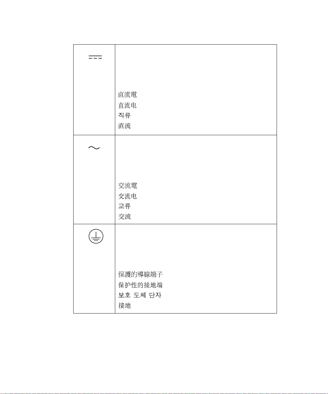
Direct current
Courant continu
Gleichstrom
Corrente continua
Corriente continua
Alternating current
Courant alternatif
Wechselstrom
Corrente alternata
Corriente alterna
Protective conductor terminal
Borne du conducteur de protection
Schutzleiteranschluss
Ter m ina le di conduttore con protezione
Borne del conductor de tierra
Page 11

Commonly Used Symbols (Continued )
Frame or chassis terminal
Borne du cadre ou du châssis
Rahmen- oder Chassisanschluss
Ter m ina le di struttura o telaio
Borne de la estructura o del chasis
Caution or refer to manual
Attention ou reportez-vous au guide
Vorsicht, oder lesen Sie das Handbuch
Prestare attenzione o fare riferimento alla guida
Actúe con precaución o consulte la guía
Caution, hot surface or high temperature
Attention, surface chaude ou température élevée
Vorsicht, heiße Oberfläche oder hohe T emperatur
Precauzione, superficie calda o elevata temperatura
Precaución, superficie caliente o temperatura elevada
Page 12

Commonly Used Symbols (Continued )
Caution, risk of electric shock (high voltage)
Attention, risque de commot ion électri que (haut e tension )
Vorsicht, Elektroschockgefahr (Hochspannung)
Precauzione, rischio di scossa elettrica (alta tensione)
Precaución, peligro de descarga eléctrica (alta tensión)
Caution, risk of needle-stick puncture
Attention, risques de perforation de la taille d’une aigui lle
Vorsicht, Gefahr einer Spritzenpunktierung
Precauzione, rischio di puntura con ago
Precaución, riesgo de punción con aguja
Caution, ultraviolet light
UV
Attention, rayonnement ultrviolet
Vorsicht, Ultraviolettes Licht
Precauzione, luce ultravioletta
Precaución, emisiones de luz ultravioleta
Page 13

Commonly Used Symbols (Continued )
Fuse
Fusible
Sicherung
Fusibile
Fusible
1
0
Electrical power on
Sous tension
Netzschalter ein
Alimentazione elettrica attivata
Alimentación eléctrica conectada
Electrical power off
Hors tension
Netzschalter aus
Alimentazione elettrica disat tivata
Alimentación eléctrica desconectada
Page 14

Waters Micromass ZQ Detector Information
Intended Use
Waters designed the Waters® Micromass® ZQ™ Detector to with an HPLC system to
determine mass-to-charge ratio (m/z) for a wide range of analytes.
Biological Hazard
When you analyze physiological fluids, take all necessary precautions and treat all
specimens as potentially infectious. Precautions are outlined in “CDC Guidelines on
Specimen Handling,” CDC – NIH Manual, 1984.
Calibration
Follow the calibration methods set forth in this guide, using pure standards. The
concentration range should cover the entire range of quality-control samples, typical and
atypical specimens.
Quality Control
Routinely run three quality-control samples. Quality-control samples should represent
subnormal, nor m al, and above-norm al levels of a compound. Ensure that quality-control
sample results are within an acceptable range, and ev aluate precision from day to day and
run to run. Data collected when quality-control samples are out of range may not be valid.
Page 15

Table of Contents
Preface ....................................................................................... 23
Chapter 1
Overview ........ .............. .............. ............... ......... ............... .............. . 27
1.1 About the Micromass ZQ Detector........................................ 27
1.2 Theory and Principles of Operation ...................................... 28
1.3 MassLynx 4.0 Software......................................................... 29
Chapter 2
Installing .......................................................................................... 30
2.1 Site Selection and Power Requirements............................... 31
2.2 Unpacking and Inspecting..................................................... 32
2.3 Installing the Detector ........................................................... 33
2.3.1 Installing the Rotary Pump ........................................ 33
2.3.2 Installing the Oil Return Connection Kit..................... 34
2.3.3 Connecting the Nitrogen Supply and Exhaust........... 35
2.3.4 Connecting the Rheodyne Injector (for Manual
Injections).................................................................. 37
2.3.5 Installing the ESI Probe............................................. 38
2.3.6 Connecting the Workstation....................................... 39
2.3.7 Preparing the Syrin ge an d Syringe Pump ................. 40
Table of Contents 15
Page 16

Chapter 3
Tuning ............................................................................................ 41
3.1 Opening MassLynx and Starting the Instrument................... 41
3.2 Tuning in ESI Mode............................................................... 43
3.2.1 Specif ying Parameter Settin gs on the ES+
Source Page....................... ..... .... ..... ..... ................... . 44
3.2.2 Specif ying Parameter Settin gs on the
Analyser Page ........................................................... 46
3.3 Tuning in APCI Mode ............................................................ 47
3.3.1 Preparing the Source for APCI Operation ................. 48
3.3.2 Installing the Tee Fitting............................................. 49
3.3.3 Specifying Parameters on the APCI+ Source
Page.......................................................................... 49
3.4 Readbacks............................................................................ 52
Chapter 4
Calibrating ....................................................................................... 54
4.1 Setting Up the Calibration File.............................................. 54
4.2 Setting Calibration Parameters ............................................. 55
4.2.1 Tune Window Setting s ............. .... .................... .... ..... . 55
4.2.2 Instrum en t Thresh old Settin gs Dialog Box ...... .... ..... . 58
4.2.3 Automatic Calibration Check Dialog Box ................... 59
4.2.4 Calibration Parameters Dialog Box............................ 60
4.2.5 Mass Measure Dialog Box......................................... 62
4.2.6 Automatic Calibration Dialog Box .............................. 63
4.2.7 Calibration Acquisition Dialog Box............................. 64
Table of Contents 16
Page 17

Chapter 5
Maintaining ...................................................................................... 73
5.1 Considerations...................................................................... 73
5.2 Routine Maintenance............................................................ 75
5.2.1 Checking the Rotary Pump Oil .................................. 75
5.2.2 Replacing the Pump Oil............................................. 75
5.2.3 Gas-Ballasting the Rotary Pump............................... 78
5.2.4 Replacing the Oil Mist Filter....................................... 79
5.2.5 Cleaning the Source Assembly.................................. 80
5.2.6 Cleaning the APCI Probe Tip..................................... 91
5.2. 7 Cleaning and Replacing th e Corona Discharge
Needle....................................................................... 91
5.3 Replacing Parts..................................................................... 92
5.3.1 Replacing the Ion Block Cartridge Heater................. 92
5.3.2 Replacing the Stainless Steel Capillary..................... 93
5.3.3 Replacing the ESI Probe Tip ..................................... 95
5.3.4 Replacing the APCI Fused Silica Capillary and
Filter Pad.................. ..... ..... ..... ................... ..... .... ..... . 96
5.3.5 Replacing the APCI Probe Heater............................. 98
Chapter 6
Troubleshooting ............................................................................... 99
6.1 Safety and Handling.............................................................. 99
6.2 Component Hardware Troubleshooting............................... 101
6.3 Inspecting the APCI Probe.................................................. 107
Table of Contents 17
Page 18

Appendix A
Using the ESCi Multi-Mode Ionization Source................................ 108
A.1 Preparing for Oper ation . ..... ..... ................... ..... ..... ..... ........ 108
A.1.1 Installing the Corona Discharge Needle.................. 108
A.1.2 Setting Up MassLynx .............................................. 110
A.2 Daidzein Test ... ..... ..... .... ..... ..... ..... ................... ..... ..... .... .... 117
A.2.1 Test Conditions ...................................................... 118
A.2.2 Signal-to-Noise Ratio .............................................. 118
Appendix B
Specifications ................................................................................. 119
B.1 ZQ Detector Specifications ................................................ 119
B.2 ESCi Multi-Mode Ionization Source Specifications ........... 121
Appendix C
Accessories and Spare Parts ......................................................... 122
Index ..................................................................................... 129
Table of Contents 18
Page 19

List of Figures
2-1 Installing the Detector....................................................................30
2-2 Pump Oil Level...............................................................................33
2-3 Fitting the Gas Ballast and Hose adaptors to the Rotary Pump.... 35
2-4 ZQ Detector Rear Panel ................................................................36
2-5 Nitrogen Stud.................................................................................36
2-6 Drying Gas Exhaust Bottle ............................................................37
2-7 Rheodyne Injector........... ......... ......... .......... ......... ..........................38
2-8 ESI Probe in Situ...........................................................................39
2-9 Syringe Pump................................................................................40
3-1 MassLynx Login Dialog Box...........................................................41
3-2 MassLynx Main Window................................................................ 42
3-3 Tune Window Displaying the ES+ Source Page ............................ 43
3-4 Syringe Selection Dialog Box ........................................................45
3-5 Tune Window Displaying the Analyser Page..................................47
3-6 Combined Flow into the Tee..........................................................49
3-7 Tune Window Displaying the APCI+ Source Page.........................50
3-8 Readbacks Dialog Box................................ ...................................52
3-9 Diagnostics Page Readbacks........................................................53
4-1 Calibration Window........................................................................54
4-2 Open Dialog Box............................................................................55
4-3 Tune Window Displaying the ES+ Source Page ............................ 57
4-4 Tune Window Displaying Analyser Page Parameters....................58
4-5 Instrument Threshold Settings Dialog Box ....................................59
4-6 Automatic Calibration Check Dialog Box.......................................59
4-7 Calibration Pa rameters Dialog Box................................................60
4-8 Mass Measure Dialog Box.............................................................62
4-9 Automatic Calibration Dialog Box ..................................................63
4-10 Calibration Acquisition Setup Dialog Box ......................................65
List of Figures 19
Page 20

4-11 Display Calibration Graphs Dialog Box..........................................67
4-12 Calibrate Window Showing ZQ-4000 Calibration Graphs..............69
5-1 Rotary Pump Assembly Fitted with Oil Mist Filter..........................76
5-2 Rotary Pump Oil Filler Plug, Drain Plug, and Sight Glass.............77
5-3 Isolation Valve................................................................................79
5-4 Oil Mist Filter Assembly.................................................................80
5-5 Pumping Block Assembly..............................................................82
5-6 Ion Block Assembly .......................................................................83
5-7 Probe Assembly in Position on the Source ....................................84
5-8 ZQ Detector Front View.................................................................85
5-9 Source Showing the Corona Discharge Needle............................86
5-10 Ion Block........................................................................................86
5-11 Sample Cone and Cone Gas Nozzle.............................................87
5-12 Ion Block Rear View ......................................................................88
5-13 Hexapole Assembly.......................................................................89
5-14 Ion Block Cartridge Heater............................................................92
5-15 Replacing the Heater Car tridge.....................................................93
5-16 ESI Probe Tip with Capillary Protruding 0.5 mm...........................95
A-1 ZQ Mass Detector, Front View ...................................................109
A-2 Installing the Corona Needle ...................................................... 110
A-3 Tune Window ..............................................................................110
A-4 Tune Window Showing Options List with ESCi Mode Selected .111
A-5 Tune Window, Diagnostics Page ................................................112
A-6 Selecting the ESCi+ or ESCi- Ionization Mode ...........................112
A-7 Selecting the Ion Mode in the MassLynx Peak Editor ................ 113
A-8 Tune Window as it Appears During ESCi Operation ..................114
A-9 Function List Editor Window (Blank) ...........................................115
A-10 Function:n MS Scan Dialog Box ................................................. 115
A-11 Function List Editor Window Showing Specified Functions ........116
A-12 ESCi Mode Disabled ...................................................................117
A-13 Daidzein (m/z = 255.2 [M + H] and 253.2 [M – H]) ..................... 117
List of Figures 20
Page 21

List of Tables
2-1 Installation Site Requirements ......................................................31
3-1 ES+ Source Page Parameters ......................................................43
3-2 Source and Desolvation Temperature Settings........................ 44
3-3 Analyser Page Parameters...................................................... 46
3-4 APCI+ Source Page Parameters ............................................. 49
4-1 Recommended Calibration Acquisitions Setup Parameters ......... 65
4-2 Calibration Failure Troubleshooting ......................................... 69
5-1 Maintenance Schedule .................................................................74
6-1 Hardware Troub lesh ooting .................................. ......... ............... 101
A-1 HPLC Conditions ........................................................................118
A-2 MS Conditions ............................................................................ 118
B-1 ZQ Detector Operational Specifications .....................................119
B-2 ZQ Detector Environmental Specifications................................. 120
B-3 ZQ Detector Dimensions ............................................................ 120
B-4 ZQ Detector Electrical Specifications......................................... 120
B-5 ESCi Environmental Specifications............................................ 121
B-6 ESCi Electrical Specifications..................................................... 121
C-1 Fuses .......................................................................................... 122
C-2 Probe Components..................................................................... 122
C-3 Vacuum Components................................................................. 123
C-4 Valves and Flow Meters ............................................................. 124
C-5 Kits........................................... ..................................... .......... .... 125
C-6 Power Supplies........................................................................... 125
List of Tables 21
Page 22

C-7 Source and Analyser Components............................................. 126
C-8 Washers, Screws, and Nuts....................................................... 127
C-9 Miscellaneous Components........................................................ 128
List of Tables 22
Page 23

Preface
The Waters Micromass ZQ Detector Operator’s Guide descr ibe s procedures for
unpacking, installing, using, mai nta ining, and troubleshooting the Waters
ZQ™ Detector. Its appendixes ex pl ain how to use the optional ESCi™ Multi-Mode
Ionization Source, and list instrument specifications, accessories, and spare part s.
This guide is intended for individuals who need to install, operate, maintain, and/or
troubleshoot the Micromass
ZQ Detector.
®
Organization
This guide contains the following:
Chapter 1
Chapter 2
liquid line, gas, signal, and other hardware connections.
Chapter 3
calibrate it.
Chapter 4
in MassLynx™.
Chapter 5
Chapter 6
Appendix A
describes the instrument, including its features and options.
describes how to unpack and install the instrument and how to make power ,
describes how to configure the instrument, start it operating, and tune and
describes how to set up a calibration file and specify calibration parameters
explains routine maintenance procedures.
describes troubleshooting procedures.
explains how to use the ESCi Multi-Mode Ionization Source option.
Micromass®
Appendix B
Appendix C
presents instrument specifications.
lists recommended and optional accessories and spare parts.
Related Documentation
Waters Licenses, Warranties, and Support: Provides software license and warranty
information, describes training and extended support, and tells how Waters handles
shipments, damages, claims, and returns.
Online Documentation
MassLynx Help
dialog boxes f or the base software and software options. Also includes reference
information and procedures for performing all tasks required to use MassLynx software.
Included as part of the MassLynx software.
: Describes all MassLynx windows, menus, menu selections, and
23
Page 24

Printed Doc um entation for Base Product
MassLynx User’ s Guide
MassLynx Interfacing Guide
MassLynx Security User’s Guide
MassLynx 4.0 Guide to Inlet Control
MassLynx 4.0 Guide to ZQ Data Acquisition
Wate rs Micro mass ZQ wit h MassLynx v4.0 Software a nd Instrument Verification
Procedure
Related Adobe Acrobat Reader Documentation
For detailed information about using Adobe® Acrobat® Reader, see the Adobe Acrobat
Reader Online Guide. This guide covers procedures such as viewing, navigating, and
printing electronic documentation from Adobe Acro bat Reader.
Printing This Electro nic Docu men t
Adobe Acrobat Reader lets you easily print pages, page ranges, or the entire document by
selecting File > Print. For optimum print quantity, Waters recommends that you specify a
PostScript
resolution.
®
printer driver for your printer. Ideally, use a printer that supports 600 dpi print
Documentation Conventions
The following conventions can be used in this guide:
Convention Usage
Purple
Italic Italic indicates information that you supply such as variables. It also
Courier
Courier Bold
Purple text indicates user action such as keys to press, menu selections, and commands. For example, “Click Next to go to the next
page.”
indicates emphasis and document titles. For example, “Replace
file_name with the actual name of your file.”
Courier indicates examples of source code and system output. For
example, “The SVRMGR> prompt appears.”
Courier bold indicates characters that you type or ke ys you press in
examples of source code. For example, “At the LSNRCTL> prompt ,
enter set password oracle to access Oracle.”
24
Page 25

Convention Usage
Underlined Blue I ndi cates hypert ext cross-references to a specific chapter, section,
subsection, or sidehead. Clicking this topic using the hand symbol
brings you to this topic within the document. Right-clicking and
selecting Go Back from the shortcut menu returns you to the origi-
nating topic. For example, “Monitoring Readbacks are described in
Section 3.4,
Keys T he word key refers to a computer key on the keypad or keyboard.
Screen keys ref er to the ke ys on the instrument located immediately
below the screen. For example, “The A/B screen key on the 2414
Detector displays the selected channel.”
… Three periods indicate that more of the same type of item can
optionally follow. For e xample, “You can store filename1, filename2,
… in each folder.”
>
Notes
Notes call out information that is helpful to the operator. For example:
Record your result before you proceed to the next step.
Note:
A right arrow between menu options indicates you should choose
each option in sequence. For example, “Select File > Exit” means
you should select File from the menu bar, then select Exit from the
File menu.
Readbacks”
Attentions
Attentions provide information about preventing damage to the system or equipment. For
example:
To avoid damaging the detector flow cell, do not touch the flow cell
STOP
Attention:
window.
25
Page 26

Cautions
Cautions provide information essential to the safety of the operator. For example:
Caution:
To avoid burns, turn off the lamp at least 30 minutes before removing it for
replacement or adjustment.
Caution:
To avoid electrical shock and injury, unplug the power cord before
performing maintenance procedures.
Caution:
To avoid chemical or electrical hazards, observe safe laboratory practices
when operating the system.
26
Page 27

Chapter 1 Ov erview
This chapter describes the Waters® Micromass® ZQ™ Detector, its features and options.
1.1 About the Micromass ZQ Detector
The ZQ Detector is a quadrupole mass analyser that can determine the mass-to-charge
ratio (m/z) of diverse analytes. An HPLC system, or syringe pump, delivers liquid sample
to the instrument’s analyser source. There the sample molecules ionize by means of one
of two ionization modes: electrospray (ESI) or atmospheric pressure chem ical ionization
(APCI). In ESI mode, sample molecules ionize in solution before they reach the source.
On entering the ev acuated source, they begin a desolvation process. In APCI mode, an
electrical discharge inside the source ionizes the sample molecules whereupon they
undergo desolvation.
The ions ultimately reach the quadrupole, which separates them according to their
mass-to-charge ratios. A photomultiplier then detects the mass-separated ions, amplifies
their signals, and sends the mass information to the data syst em.
Probes
An electrospray ionization (ESI) probe or an atmospheric pressure chemical ionization
(APCI) probe introduces the sample to the ion source.
1
Sample Inlet
Either of two methods deliver solvent and sample to the installed probe:
• An HPLC system – Delivers the eluent from an HPLC analysis.
• A built-in syringe pump – Delivers standard solutions or infusions of unknown
samples.
Vacuum System
An external rotary (roughing) pump and an internal split flow turbomolecular pump
combine to create the source vacuum. The turbomolecular pump evacuates the analyser
and ion transfer region.
Vacuum leaks and electrical or vacuum pump failures cause vacuum loss, which
protective interlocks guard against. The system monitors turbomolecular pump speed and
About the Micromass ZQ Detector 27
Page 28

continuously measures vacuum pressure with a built-in Pirani gauge. The gauge also
serves as a switch, discontinuing detector operation when it senses vacuum loss.
A vacuum isolation valve isolates the source from the mass analyser, allo wing routine
source maintenance without venting.
Mass Analyser (Quadrupole)
The mass analyser separates ions by mass-to-charge ratio (m/z).
Data System
The data system collects information from the mass analyser and includes these
components:
• MassLynx™ 4.0 software
• An external workstation
• An embedded PC
MassLynx software controls the workstation-based data system and mass detector
through the detector’s embedded PC. Using MassLynx, you tune the instrument, set up
and run the HPLC system, and acquire and process data. When they are part of the
system, the software also controls the autosampler and the divert and injector valves.
The workstation uses a Windows NT
environment and allows full user interaction with the keyboard or mouse. A network link
communicates between the workstation and the detector’s embedded PC.
®
, Windows® 2000, or Windows XP color graphical
1
MassLynx acquires and stores data from conventional LC detectors simultaneously with
data the mass detector acquires. It can also acquire data from selected systems, like
Waters 996/2996 Photodiode Array Detectors. Consult the MassLynx 4.0 Guide to Inlet
Control for details about MassLynx.
1.2 Theory and Principles of Operation
Electrospray Ionization (ESI)
In ESI, a high electrical voltage charges the eluent as it emerges from a nebulizer,
producing an aerosol of charged droplets. As the solvent evaporates, the droplets shrink,
developing a charge dense enough to eject ions from their s urfaces (ion evaporation). The
mass analyser then sorts the singly or multiply charged ions by mass-to-charge m/z ratio.
The analyser source can accommodate eluent flows of up to 1 mL/min. You can enhance
performance by reducing the rate of eluent flow at the ion source.
Overview 28
Page 29

Atmospheric Pressure Chemical Ionization (APCI)
A heated nebulizer vaporizes the sample. The sample ions then merge with solvent ions in
the atmospheric source, enabling proton transfers between the solvent and sample ions.
APCI generally produces both protonated and deprotonated molecular ions from the
sample. For positive ions, this ionization occurs by means of a proton transfer mechanism.
For negative ions, the mechanism is proton abstraction.
1.3 MassLynx 4.0 Software
MassLynx 4.0 software permits these major operations:
• Configuring the instrument
• Creating HPLC inlet and MS methods that define operating parameters for a run
• Tuning and calibrating the mass detector
• Running samples
• Monitoring the run
• Acquiring data
• Processing data
• Reviewing data
• Printing data
1
See the MassLynx 4.0 Guide to Inlet Control and MassLynx Help for more information on
installing and using MassLynx software.
MassLynx 4.0 Software 29
Page 30

Chapter 2 Installing
This chapter describes how to unpack and install your Waters Micromass ZQ Detector.
Figure 2-1
summarizes these procedures.
Installation
Begins
Select and Prepare
Appropriate Site
Unpack and Inspect
Install Rotary Pump
Install Oil Retur n
Connection Kit
Connect N2 and
Exhaust
Connect Rheodyne
Injector Tubing
Install
ESI Probe
Connect
Workstation
Set Up
Syringe Pump
2
Figure 2-1 Installing the Detector
Installation
Complete
30
Page 31

2.1 Site Selection and Power Requirements
Install the detector on a stable, level, and appropriately clean surface that meets the
specifications in Table 2-1
Table 2-1 Installation Site Requirements
Factor Requirement
Temperature range 15 to 28 °C (59 t o 82.4 °F)
Relative humidity
range
Bench space Width: 15.2 in. (38.1 cm)
Clearance Rear: 4.75 in. (120 mm)
Power requirements Grounded AC, 230 V, 50/60 Hz
Electromagnetic fields No nearby source of electromagnetic noise, such as NMR
Static electricity Negligible
Vibration Negligible
.
20 to 80%, noncondensing
Depth: 26 in. (66.1 cm)
Height: 23 in. (57.2 cm)
Weight: 210 lb. (95.3 kg)
Right side: 20 in. (0.5 m) to allow for service access.
Movable equipment can be located as close as 4.75 in.
Note:
(120 mm).
Left side: 0.0 in./mm
Top: 11 in. (28 cm)
systems or magnetic sector mass spectrometers
2
STOP
STOP
Attention:
top, sides, and rear of the instrument.
Attention:
before installing the instrument. Read ings of less than 208 VAC indicate the need for a
step-up transformer.
To avoid overheating the instrument, allow the prescribed clearances at the
To avoid damaging the instrument, measure the voltage at the 230 VAC outlet
Installing 31
Page 32

2.2 Unpacking and Inspecting
The Waters Micromass ZQ system is shipped in several cartons. Among them, they
contain these items:
• Micromass ZQ Detector with Startup Kit
• Rotary pump
• MassLynx wo rk stati o n
• MassLynx 4.0 documentation set
• Waters Micromass ZQ Detector Operator’s Guide
Required Material
Utility knife or scissors
Procedure
1. Note any tipping or shock indicators on the cart ons that shipping might have
triggered. Also, inspect the carton for damage.
2. Cut and remove the straps that secure the large carton.
3. Lift the carton off the pallet.
4. Remove foam packing material from the top of the instrument.
5. Remove the Star tup Kit, and set it aside.
6. Lift the detector from the foam support on the pallet and carefully set the unit down
on a bench.
Caution:
and place it on the bench.
The instrument should overhang the bench top by several inches to allow the
Note:
waste tube, which extends from the lower-right corner, a straight descent to the
liquid waste container.
7. Che ck the Star tup Kit contents against the accompa nying parts list to confirm that
all items are included.
8. O pen the carton containing the rotary pump, then remove the packing material and
Star tup Kit.
9. Care fully remove the rotary pump, and set it temporarily down on a level surface.
At least four people must lift the instrument from its shipping pallet
2
Unpacking and Inspecting 32
Page 33

Contacting Waters Technical Service
Inspect all items for damage. Immediately report any shipping damage to both the carrier
and Waters. Nort h American customers who report damage should cont act Waters
Technical Ser v ice at 800 252-4752. All others should call their local Waters subsidiary or
Waters corporate headquarters in Milford, Massachusetts (U.S.A.).
2.3 Installing the Detector
This section describes how to install the Waters Micromass ZQ 2000 and ZQ 4000
Detectors.
2.3.1 Installing the Rotary Pump
2
Attention:
STOP
1. Place the rotary pump on the floor, within 5 feet of the instrument. Place the PTFE
2. Fill the pump with oil:
starting it.
drip tray beneath the pump.
a. Rem ove the fille r plu g.
b. Pour oil into the pump until the level reaches the MAX mark on the bezel at the
oil-level sight glass. If the level exceeds the MAX mark, remove the drain plug,
and let the excess oil drain (Figure 2-2
c. After a few minutes, recheck the oil. If the level is now below the MAX mark, add
the appropriate amount of oil.
d. Refit the oil filler plug. Finger tighten it. Do not overtighten it.
The rotary pump is shipped without oil. You mus t f ill it wi th o il before
).
Oil Fi ller Plug
MAX
MIN
Figure 2-2 Pump Oil Level
Installing 33
Page 34

Use Ultragrade 19 or Inland Q45 oil only. Refer to the manufacturer’s manual
Note:
for more information about filling the pump with oil.
3. Attach the NW 25 tee, included in the Start up Kit, to the inlet of the rotary pump
using the NW25 center ring and clamp (Figure 5-1
4. Attach a length of 1-inch ID vacuum hose to each open por t on the NW25 tee. Use
the NW25 flanges, center rings, and clamps provided in the Startup Kit.
5. Con nect the opposit e ends of the two lengths of vacuum hose to the two straight
NW25 vacuum ports on the detector’s rear panel. Use NW25 flanges, center rings,
clamps, and elbows, as necessary.
6. Remove the nozzle fitting on the pump exhaust port, and replace it with the NW25
flange and O-ring from the Startup Kit.
Ensure the NW25 flange is tight. Pump vibration can loosen it, causing oil to
Note:
leak.
7. Con nect the oil mist filter assembly to the pump exhaust port. Use an NW25 center
ring and clamp.
8. Con nect an NW25 nozzle fitting to the oil mist filter assembly. Use an NW25 center
ring and clamp.
9. Con nect the 12-mm clear PVC exhaust tubing to the NW25 nozzle fitting. Secure
the tubing with a hose clamp.
10. R ou te the open end of the exhaust tubing to a suitable exhaust vent.
11. Remove the drain plug and bonded seal from the oil mist filter housing. Save the
drain plug for future use.
12. Connect the female end of the rotary pump power cord to the connector on the
rotary pump relay box. Connect the male end of the power cord to the rotary pump
connector on the instrument’s rear panel.
13. T urn the power switch to On.
).
2
The pump will not start at this time. It is controlled by the system software.
Note:
2.3.2 Installing the Oil Return Connection Kit
The oil return connection kit collects excess oil from the oil mist filter housing and returns it
to the rotary pump oil reservoir.
1. Insta ll the drain adaptor and bonded seal onto the oil mist filter drain port
(Figure 2-3
).
Installing the Detector 34
Page 35

1. E1/E2M Pump
2. Filters
3. Wire Mesh
4. Circlip
5. O-Ring
6. Gas Ballast Adaptor
7. Bonded Seal
8. Hose Adaptor
9. Bonded Seal
10. Banjo Bolt
Figure 2-3 Fitting the Gas Ballast and Hose adaptors to the Rotary Pump
2. Remove the circlip , wire mesh, and filters from the gas ballast inlet on the pump.
3. Insert the gas ballast adaptor and O-ring into the gas ballast inlet por t on the pump.
4. Connect the hose adaptor to the gas ballast adaptor. Use t he banjo bolt and the two
bonded seals.
5. Estimate how much fle xible oil return tubing you need to loosely connect the oil mist
filter housing’s drain port to the pump’s inlet port. When fitted, the tube must be free
of kinks or tight bends.
6. Cut the tubing, ensuring the cut ends are burr-free and square.
7. Lu bri cate the restrictor with oil, then inser t it into one end of the tube.
8. Connect one end to the drain adaptor on the oil mist filter housing, and the other end
to the hose adaptor.
9. Secure the ends of the tube with hose clips.
2
2.3.3 Connecting the Nitrogen Supply and Exhaust
1. Con nect one end of a length of the 6-mm PTFE tubing to the N2 In port on the rear
of the instrument (Figure 2-4
).
Installing 35
Page 36

N2 In Port
N
Rotary Pump
Po wer Connection
Figure 2-4 ZQ Detector Rear Panel
2. At tach a nitrogen regulator to the nitrogen supply, and install the 6-mm stud
(Figure 2-5
) into the regulator outlet.
Figure 2-5 Nitrogen Stud
2
Vacuum Ports
Exhaust
2
3. Con nect the free end of the 6-mm PTFE tubing to the 6-mm stud.
4. Locate the drying gas exhaust bottle (Figure2-6
5. Cut a length of 10-mm tubing long enough to connect the instrument to the drying
gas exhaust bottle. Connect one end of the tubing to the exhaust por t on the rear
panel. Connect the other end to one of two ports on the dryin g gas exhaust bottle.
6. Cut a second length of 10-mm tubing long enough to connect the dr ying gas
exhaust bottle to the exhaust vent. Insert one end of the tubing into the remaining
port on the dr yin g gas exhaust bottle. Route the other end to the exhaust vent.
) in an accessible area.
Installing the Detector 36
Page 37

Figure 2-6 Drying Gas Exha ust Bottle
2
Attention:
STOP
7. Route the PTFE waste tubing from the detector’s lower-right corner to a suitable
liquid waste container.
nitrogen, the other for the rotary pump. Vent them to atmosphere through
separate exhaust lines. Oil mist can seriously damage the instrum ent when
the nitrogen exhaust line connects with the rotary pump exhaust line. Your
warranty does not cover damage caused by routing exhaust lines incorrectly.
The instrument requires two separate exhaust systems, one for
2.3.4 Connecting the Rheodyne Injector (for Manual Injections)
Refer to Figure 2-7 for this pr ocedure .
1. Con nect the PTFE waste tube to injector por t 5.
2. Insta ll the needle port fitting onto injector port 6.
3. Connect the 10-µL injection loop between injector ports 1 and 4.
4. Connect the LC system tubing to injector port 2.
Installing 37
Page 38

2
3
(To Source)
4
Figure 2-7 Rheodyne Injector
2.3.5 Installing the ESI Probe
1
6
2
5
Refer to Figure 2-8 for this proced ure .
1. Connect the PTFE tubing from the probe adjustment flange to the desolvation gas
port on the front panel.
2. Remove the protective sleev e, if fitted, from the electrospray probe tip.
3. Slide the probe into the hole in the probe adjustor plate until the probe body rests on
the probe adjustment flange. The probe identification contacts must touch the
screws on the probe adjustment flange.
4. Secure the probe with the two knurled thumbscrews.
5. Connect the 4-mm PTFE tubing from the probe to the nebulizer gas port.
6. Con nec t the electr ic al lea d from the probe to the capillary connector on the front
panel.
Installing the Detector 38
Page 39

Desolvati on Ga s Port
Source Cable
Nebulizer Gas Port
Probe Adjustor
Probe Cable
Knurled Thumbscrews (2)
Probe
Flange
Source Cover Clip
Figure 2-8 ESI Pr obe in S itu
2.3.6 Connecting the Workstation
Waters ships the workstation with preinstalled MassLynx software. Before connecting the
workstation to the instrument, set it up according to its accompanying instructions. You
should locate the workstation within 16 feet (5 meters) of the instrument.
1. Co nnect one end of the network cable to the appropriate port on the rear panel of
the detector.
2. Co nnect the other end of the network cable to the port labele d ZQ on the
workstation rear panel.
Probe Adjustor Plate
Source Cover
Source Cover Clip
2
Caution:
installation procedures in the previous sections.
Do not connect the instrument’s power supply cord until you complete the
Installing 39
Page 40

To connect the instrument to the power source:
1. Sele ct the correct power cord for your location.
2. Connect the female end of the power cord t o the power port on the rear panel of the
instrument.
2.3.7 Preparing the Syringe and Syringe Pump
This section refers to the 250-µL Hamilton syringe, various syringe fittings, and the API
Setup Solution (polypropylene glycol/reserpine/cyclodextrin) found in the Startup Kit.
1. Flush the syringe three times with methanol or a volume-to-volume mixture of 70%
methanol : 30% water .
2. Lo ad the syrin ge with the setup solution, and connect the Rheodyne 9013 needle
port fitting to the PEEK
3. Clip the ground cable (with the plug-in clip), located on the lower-right side of the
front panel, into the syringe needle.
union, finger tightening it.
2
Caution:
4. Fit the syringe into the syringe pum p, and set the syringe stop accordingly
(Figure 2-9
).
Caution:
certain syringe types from breaking. Nevertheless, as added protection
against syringe breakage, you should set the syringe stop adjustor. This
prevents the syringe plunger from traveling its full stroke inside the syringe
barrel, reducing the potential for breakage.
To avoid electrical shock, always ground the needle.
The syringe pump includes a positive syringe stop to prevent
Needle Port
Syringe
Syringe Stop Adjustor
Figure 2-9 Syringe Pump
TP01745
Installing the Detector 40
Page 41

Chapter 3 Tuning
Tuning involves adjusting source settings, analyser settings, and gas flows to produce
optimal peak intensities.
After you tune, calibrate the instrument in electrospray (ESI) mode, even if you intend to
operate it in APCI mode. See Section 3.3.3
3.1 Opening MassLynx and Starting the Instrument
1. Dou ble-click the MassLynx V4.0 desktop icon to open the application. The
MassLynx Login dialog box appears (Figure 3-1
for details about tuning in APCI mode.
).
3
Figure 3-1 MassLynx Login Dialog Box
2. Compl ete the Logon Name, Password, and Domain fields .
The Login dialog box appears only when you enable MassLynx security. Otherwise,
Note:
the MassLynx Main window (Figure 3-2
desktop icon. See the MassLynx Secu rity User’s Guide (version 4.0) for details about
enabling MassLynx security.
) appears after you click the MassLynx V4.0
Opening MassLynx and Starting the Instrume nt 41
Page 42
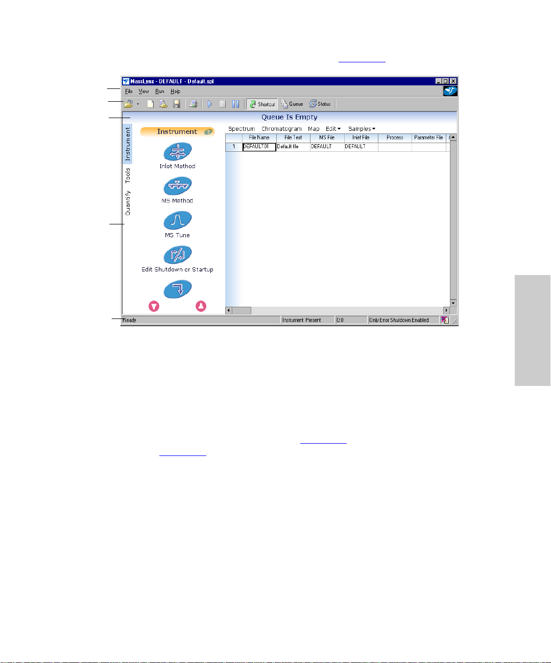
3. Click OK. The MassLynx Main window appears (Figure 3-2).
Menu Bar
Toolbar
Information Bar
Shortcut Bar
Status Bar
3
Figure 3-2 MassLynx Main Window
After initiating, the Main window displays “Instrument Present” in the status
Note:
bar.
4. The shortcut bar should appear in the MassLynx Main window, and “Instrument”
should appear at its top. If it fails to appear, click Shortcut, in the toolbar, to open it.
Then click Instrument, at the left edge of the shortcut bar.
5. Select MS Tune from the Main window (Figure 3-2
window (Figure 3-3
).
) shortcut bar to open the Tun e
Tuning 42
Page 43

Figure 3-3 Tune Window Displaying the ES+ Source Page
3.2 Tuning in ESI Mode
Table 3-1 describes the Tune window’s ES+ Source page parameters.
The voltage parameters shown in this table optimize sensitivity and s tab ility. The
Note:
temperature and flow rate parameters control the extent of solvent evaporation and adduct
formation.
Table 3-1 ES+ Source Page Parameters
Parameter Description
Capillary voltage Enhances or suppresses ion density by supplying excess charge
to droplets. Optimal voltages: 2 to 4 kV for positive ions and 2 to
3 kV for negative ions.
Cone voltage Helps draw ions into the first vacuum region (20 to 70 V optimal).
Extractor voltage Focuses ions toward the hexapole RF lens (3 to 10 V optimal).
Increasing voltage can induce fragmentation.
RF Lens voltage Focuses ions toward the center of the quadrupole (~0.5 V).
3
Tuning in ESI Mode 43
Page 44

Table 3-1 ES+ Source Page Parameters (Continued)
Parameter Description
Source temperature See Table 3-2.
Desolvation
temperature
Desolvation gas flow Optimizes gas flow depends on mobile phase composition and
Cone gas flow Helps reduce adduct ions and keep the sample cone clean (50
See Table 3-2.
flow rate (>100 L/hr).
to150 L/hr).
Source and Desolvation Temperatures
The Source and Desolvation temperature settings control desolvation for a specified flow
rate. Table 3-2
Table 3-2 Source and Desolvation Temperature Settings
gives temperature ranges for specific flow rates.
HPLC Flow
Rate (µL/hr)
<100 80 to 100 100 to 350
100 to 250 100 to 130 350 to 400
250 to 1000 130 to 150 400 to 450
Source Temperature oC Desolvation Temperature oC
3.2.1 Specifying Parameter Settings on the ES+ Source Page
1. Click (API Gas) in the Tune window to toggle the nitrogen flow to On.
Attention:
STOP
2. Make sure the instrument is operating, noting whether peak activity appears in the
Tune window’s Peak Display area (Figure 3-3
(indicated by no peaks), click Press for Operate.
supply once it has been shut off. Otherwise, the sudden inrush of gas can
damage the flow meter.
You must toggle API gas to Off before reopening the nitrogen
). If the instrument is not operating
3
Tuning 44
Page 45
3. Click the ES+ Sou rce ta b, and specify these suggested star ting parameters in the
corresponding fields of the ES+ Source page.
Parameter Suggested V alue
Capillary (kV) 3.5
Cone (V) 60
Extractor (V) 3
RF Lens (V) 0.5
Source Temp (oC) 80
Desolvation Gas Flow (L/hr) 300
Desolvation Temp (oC) 150
Cone Gas Flow (L/hr) 50
Attention:
STOP
4. Sele ct all four Peak Editor fields, and enter these mass assignment values.
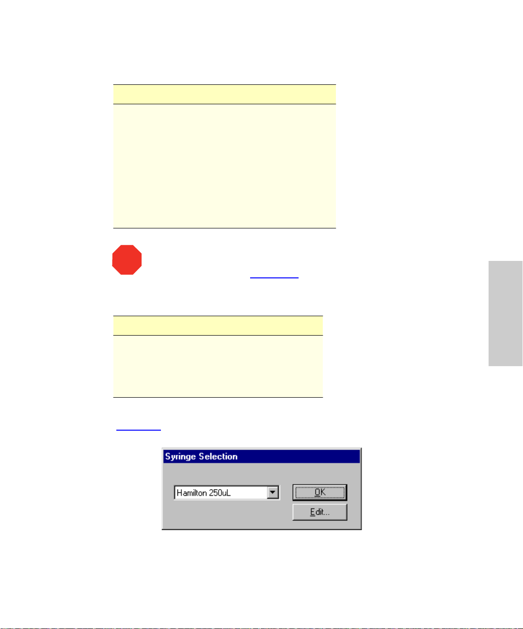
5. Select Options > Syringe Type. The Syringe Selection dialog box appears
(Figure 3-4
gas flow, desolvation temperature, and cone gas flow reach their setpoints
before proceeding. See Section 3.4
Mass Span Gain
175.1 5 10
609.3 5 10
1080.8 5 10
2034.6 5 10
).
Monitor readbacks, letting the source temperature, desolvation
for details about monitoring readbacks.
3
Figure 3-4 Syringe Selection Dialog Box
Tuning in ESI Mode 45
Page 46

6. Ensure th e drop-down list displays Hamilton 250uL, then click OK.
7. Set the syringe pump to deliver 10 µL/min by entering that rate in the Pump Flow
field of the Analyser page (Figure 3-5
8. C l ick (Syringe pump) to infuse the startup s olution into the source.
9. Click the Analyser tab, and ensure the syringe pump flow rate is 10 µL/min.
10. Turn the probe adjustor (see Figure 2-8
peak intensities.
11. A dju st the capillar y, cone, extractor, and RF lens voltages to optimize peak
intensities.
).
) in one direction or the other to optimize
3.2.2 Specifying Parameter Settings on the Analyser Page
Analyser settings optimize mass peak resolution. With span settings at 5, the bases of
mass peaks as they appear on the Tune window Analyser page should measure 1 da.
The parameters LM Resolution, HM Resolution, and Ion Energy optimize resolution.
Note:
Table 3-3 describes the Tune window’s Analyser page parameters.
Table 3-3 Analyser Page Parameters
Parameter Description
LM Resolution
HM Resolution
Ion Energy (V) Decreases resolution. Set between –1 and 3 V, as low as
Multip lie r (V) Modifies gain (attenuation). Settings between 400 and 450
1. Click the Analyser tab. The Tune window Analyser page appears (Fi gure 3-5
Affect mass peak concentration. Usually, 15, an arbitrary
unit, yields adequate mass resolution. Increasing the value
lowers sensitivity; decreasing it enhances sensitivity.
possible without reducing peak intensity.
yield a suitable signal-to-noise balance.
3
).
Tuning 46
Page 47
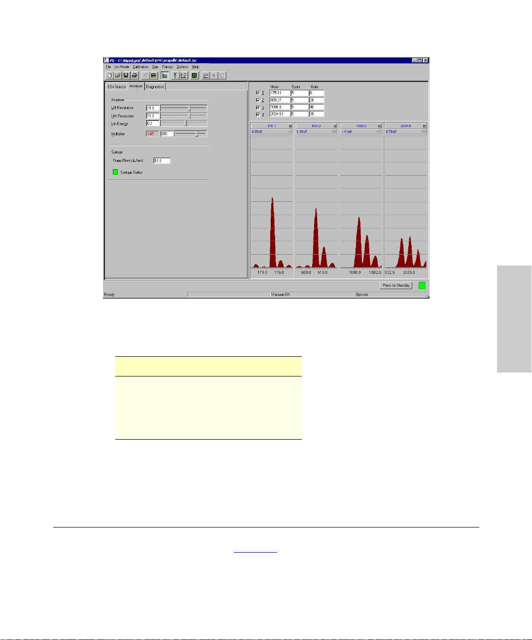
Figure 3-5 Tune Window Displaying the Analyser Page
2. Specify these suggest ed starting parameters in the Analyser page fields.
Parameter Suggested V alue
LM Resolution 15
HM Resolution 15
Ion Energy 0.3
Multiplier 650
If you change HM and/or LM Resolution after calibrating the instrument, you should
Note:
recalibrate. Otherwise, any data the instrument acquires could fall outside the calibration
mass ran ge.
3.3 Tuning in APCI Mode
After you tune and calibrate (see Chapter 4 for calibration information) in ESI mode, you
may tune for APCI operation. This entails preparing the source, installing a tee fitting
upstream of the probe, and specifying APCI parameters.
3
Tuning in APCI Mode 47
Page 48

3.3. 1 Prepa ring the Source for APCI Operation
To prepare the source for APCI tuning when the instrument is in ESI mode:
1. Prepare t he syr inge according to the procedure in Section 2.3.7
Setup Solution from the Start up K it.
2. Click Press for Standby on the lower right of the Tune window.
3. Disconnect the nebulizer gas line and both electrical connections from the front
panel.
4. Remove the ESI probe.
5. Insert the APCI probe into the source, tightening the two thumbscrews.
6. Con nect the APCI nebulizer and desolvation gas lines at the front panel.
7. O pen the source enclosure cover.
Caution:
temperature, even with the source enclosure removed.
8. Remove the blanking plug from the corona pin mounting contact, and fit the corona
discharge pin (Figure 5-9
the sample cone.
9. Close the source enclosure cover.
10. Connect the electrical lead to the Source/Probe receptacle on the front panel.
11. C lick Press for Operate.
The source is now ready for APCI operation.
The ion source block is hot. It can reach 150 °C, maintaining its set
). Align the tip of the corona discharge pin with the tip of
, loading it with API
3
STOP
Attention:
and the probe inserted.
Do not start the liquid flow until the gas flow and probe heater are switched on
Tuning 48
Page 49

3.3.2 Installing the Tee Fitting
To optimize APCI peaks, temporarily install a tee fitting to merge the sample flow from the
syringe pump with the solvent flow from an HPLC pump. The combined sample/solvent
stream flows into the probe (Figure 3-6
).
Syringe Pump
Flow
Combined Flow
into Probe
Figure 3-6 Combined Flow into the Tee
1. Connect the HPLC pump tubing to injector port 2 (see Figure 2-7
2. Con nec t the capillary from the syringe pum p to one of the tee’s three ports.
3. Con nect a 1/16-in. OD × 0.007 in. ID × 1 M tube between injector por t 3 and a
second tee port.
4. Connect another 1/16-in. OD × 0.007 in. ID × 1 M tube from APCI probe to the tee’s
third port.
HPLC Pump Flow
From Injector Port 3
3.3. 3 Specifying Parameters on t he APCI+ S ource Page
Table 3-4 describes the APCI+ Source page parameters.
Table 3-4 APCI+ Source Page Parameters
Parameter Description
Corona Affects sensitivity. The amount of current required depends on
the polarity of both the compound and mobile phase.
Optimize when mobile phase is present.
APcI Probe Temp Affects sensitivity. Start at 650 oC and reduce in 50o steps,
allowing time for stabilization to take place before reading.
Optimize while mobile phase is flowing.
Desolvation Gas flow rate usually affects signal intensity only marginally.
Nevertheless, adjusting it can suppress chemical background
noise.
Cone Gas Gas flow rate can minimize formation of solvent adducts.
for port positions).
3
Tuning in APCI Mode 49
Page 50

1. Select Ion Mode > APC I+ from the Tune window (Figure 3-3). The APCI+ Source
page appears (Figure 3-7
Figure 3-7 Tune Window Displaying the APCI+ Source Page
).
3
2. C l ick (API Gas) in the Tune window to toggle the nitrogen flow to On.
Attention:
STOP
Note:
operational mode. To remedy this, click
supply once it has been shut off. Otherwise, the sudden inrush of gas can
damage the flow meter.
If you do not observe any peak activity, the instrument may not be in
You must toggle API gas to Off before reopening the nitrogen
Press for Operate
.
Tuning 50
Page 51

3. Specify these suggest ed parameters in the APCI + Sourc e page fields.
Parameter Suggested V alue
Corona (µA) 0.1
Cone (V) 48
Extractor (V) 3
RF Lens (V) 0.0
Source Temp (oC) 120
Desolvation Gas Flow (L/hr) 300
APcI Probe Temp (oC) 500
Cone Gas Flow (L/hr) 50
Attention:
STOP
4. Sele ct all four Peak Editor fields, and enter these mass assignment values.
5. Start the LC pump, specifying a 1 mL/min flow rate.
6. C l ick (Syringe pump) to infuse the star tup solution into the source.
7. Click the Analyser tab, and ensure the syringe pump flow rate is 10 µL/min.
Turn the probe adjustor (see Figure 2-8
intensities.
flow, desolvation temperature, and cone gas flow reach their setpoints. See
Section 3.4
Mass Span Gain
175.1 5 10
609.3 5 10
1080.8 5 10
2034.6 5 10
Before proceeding, let the source temperature, desolvation gas
for information about monitoring readbacks.
) in either direction to optimize peak
3
Tuning in APCI Mode 51
Page 52

3.4 Readbacks
Readbacks report current instrument performance in most of the parameters whose
values you specify on the Tune window’s pages. They appear as red numerals in read-only
fields. These fields are adjacent to those that contain the parameters’ set values. Monitor
readbacks to determine whether the instrument performs to your parameter settings.
MassLynx provides readbacks on all Tune window pages. You can, howev er, prevent them
from appearing on the Source and Analyser pages or limit their display to those that are
out of range.
1. Select Options > Readbacks to open the Readbacks dialog box (Figure 3-8
Figure 3-8 Readbacks Dialog Box
2. Evaluate readbacks, including those on the Diagnostics page (Figure 3-9
Source and Analyser page readbacks should match the parameter values you
specify.
Some readbacks serve a broad diagnostic purp os e and therefore do not
Note:
necessarily mirror their set values. For example, a voltage readback can vary from
its set value when the instrument’s proper operation does not depend on that
voltage. In such a case, whether voltage is at all present is the more critical
measure.
). Most
).
3
Tuning 52
Page 53

Figure 3-9 Diagnostics Page Readbacks
3. Let the ion beam stabilize for 3 to 5 minutes.
4. Monitor for mass peaks, which should appear at approximately the mass values you
specified on the ES+ Source or APCI+ Source page.
3
Readbacks 53
Page 54

Chapter 4 Calibrating
Calibrating the mass scale entails setting up a calibration file and specifying calibration
parameters in MassLynx.
4.1 Setting Up the Calibration File
Before calibrating, you must remove the current calibration file and select a reference file:
1. Select Calibration > Calibrate Instrument from the Tune window (Figure 3-3
Reference File
List
2. Select NaICs2 from the reference file list to choose the reference file, if your ZQ
Calibration window appears (Figure 4-1
Figure 4-1 Calibration Window
Mass Detector is a 2000 model. Select NaICs4 if it is a 4000 model.
).
). The
4
Setting Up the Calibration File 54
Page 55

3. Select File > Open. The Open dialog box appears (Figure 4-2).
Figure 4-2 Open Dialog Box
4. Select Uncal.cal, and click Open. The Calibration window reappears.
5. Make sure the phrase “No calibration” follows the three calibration types: Static,
Scanning, and Scan Speed Compens ation.
4.2 Setting Calibration Parameters
The rest of this chapter describes how to specify calibration parameters in these windows
and dialog boxes:
• Tune window
• Instrumen t Threshold Settings dialo g box
• Automatic Calibration Check dialog box
• Calibration Parameters dialog box
• Mass Measure dialog box
• Automatic Calibration dialog box
• Calibration Acquisition Setup dialog box
4.2.1 Tune Window Settings
1. Follow the syringe preparation procedure in Section 2.3.7, this time loading the
syringe with sodium cesium iodide solution (from the API Test Kit).
2. Click (Syringe pump) in the Tune wind ow to infuse the solution into the source.
4
Calibrating 55
Page 56

3. Enter these sugges ted initial reference solution values in Tune window’s Peak
Editor.
Row Mass (ZQ 2000) Mass (ZQ 4000) Span Gain
1 172.9 172.9 5 8
2 772.5 1521.9 5 20
3 1521.9 2271.4 5 40
4 1971.6 3470.5 5 39
These settings are offered as reference points only and, once adopted, might
Note:
require adjusting.
4. Sele ct rows 1 to 4 in the Peak Editor. This specifies four mass peaks in the Tune
window’s Peak Display area (see Figure 3-3
5. Click the ES+ Sou rce ta b, and enter these suggested parameters in the
corresponding fields of the ES+ Source page (Figure 4-3
Parameter Suggested Value
Capillary (kV) 3.5
Cone (V) 50
Extractor (V) 3
RF Lens (V) 0.5
Source Temp erature (oC) 80
Desolvation Gas Flow Rate (L/hr) 250
Desolvation Temperature (oC) 120
Cone Gas Flow (L/hr) 50
).
).
4
Caution:
the source.
Fail ure to flow desolvation gas during ESI operation can damage
Setting Calibration Parameters 56
Page 57
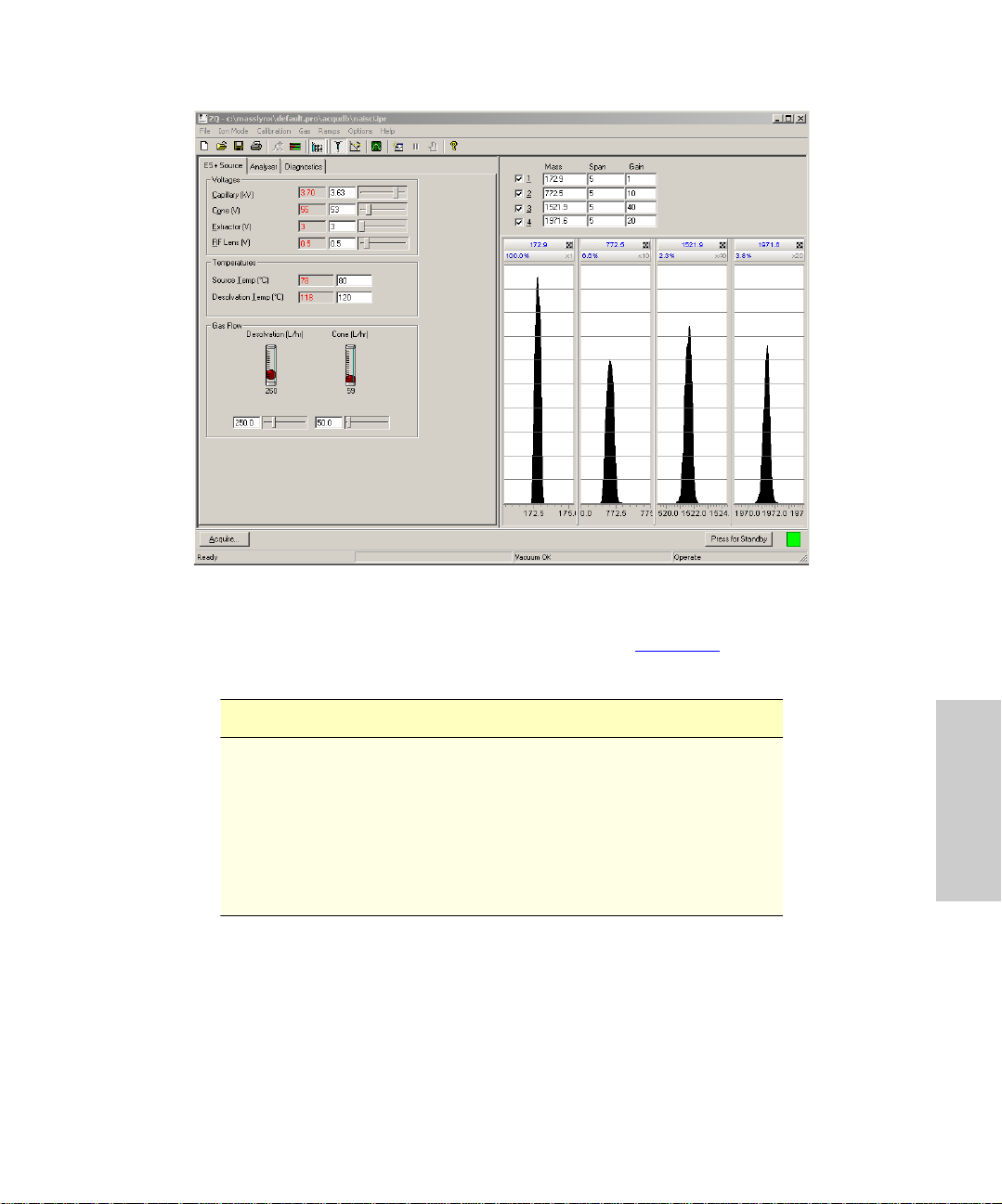
Figure 4-3 Tune Window Displaying the ES+ Source Page
6. Click the Analyser tab to open the Analyser page (Figure 4-4
suggested parameters in the corresponding fields.
Parameter Suggested Value
LM resolution 15
HM resolution 15
Ion energy (V) 0.5
Multip lie r (V) 600
Cone Gas Flow Rate (L/hr) 50
Syringe Pump Flow Rate (µL/min) 5
), and enter these
4
Calibrating 57
Page 58

Figure 4-4 Tune Window Displaying Analyser Page Parameters
7. Max imize the signal intensity of the four mass peaks in the Tune window Peak
Display:
a. Turn the probe adjustor knob (Figure 2-8
relative to the sample cone orifice.
b. Adjust the source parameters from the T une window’s ES+ Source page. These
include Capillary, Extractor, RF Lens, and Cone voltages, as well as desolvation
and cone gas flows.
8. Adjust the slide adjustors for LM ( low mass) Resolution, HM (high mass) Resolution,
and Ion Energy on the Tune window’s Analyser page (Figure 3-5
full-width-at-half-height measurement of 0.4 to 0.6 da.
Make sure you can see all ions and that none are saturated on a gain of 1X.
Note:
) to adjust the orientation of the probe
4.2.2 Instrument Threshold Settings Dialog Box
This dialog box contains parameters that control how the system preprocesses data
before sending the data to a host computer.
4
) to obtain a
Setting Calibration Parameters 58
Page 59

For most low mass-range calibrations, the instrument acquires calibration data in
continuum mode. The continuum-data parameter settings in the Instrument Threshold
Settings dialog box ensure appropriate scanning speeds.
1. Select Options > Set Instrument Threshold from the Tune window. The
Instrument Threshold Settings dialog box appears (Figure 4-5
2. Acc ept the default settings by clicking OK.
Figure 4-5 Instrument Threshold Settings Dialog Box
).
4.2.3 Automatic Calibration Check Dialog Box
Select Edit > Au toCal Check Pa r ameter s from the Calibration window (Figure 4-1). The
Automatic Calibration Check dialog box appears (Figure 4-6
Figure 4-6 Automatic Calibration Check Dialog Box
Parameters
Missed Reference Peaks – Specifies the maximum number of unmatched consecutive
peaks you allow between the reference spectrum and the acquired calibration spectrum.
).
4
Calibrating 59
Page 60
The calibration fails when the number of unmatched peaks exceeds the maximum you
specify. The default value, 2, in most cases suffices.
Maximum Std Deviation – For each pair of matched peaks, MassLynx calculates the
difference between the measured mass in the acquired calibration file and the true mass
in the reference file. The calibration fails when the standard deviation for a set of mass
differences exceeds the maximum standard deviation you specify. Decreasing the value
imposes a more stringent limit. Increasing it makes the requirement easier to meet, though
you should normally avoid setting values greater than 0.20, the default value.
Apply Span Correction – Enabling this option ensures correct mass assignment, even
when the mass scale differs from the one the instrument was calibrated with.
You should not enable this option when the mass range of interest is less than 1000
Note:
da and includes the subrange 0 to 150 da.
Check Acquisition Calibration Ranges – Waters recommends you enable this option,
which displays messages alerting you when the instrument attempts to acquire data
outside the calibrated ranges for mass and scan speed.
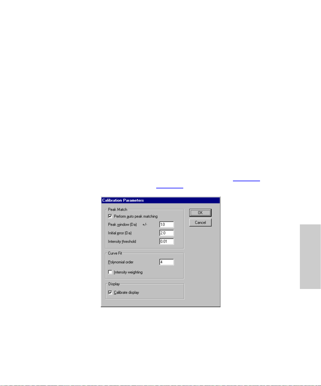
4.2.4 Calibration Parameters Dialog Box
Select Edit > Calibration Parameters from the Calibration window (Figure 4-1) to open
the Calibration Parameters dialog box (Figure 4-7
).
Figure 4-7 Calibration Parameters Dialog Box
Setting Calibration Parameters 60
4
Page 61

Parameters
Perform auto peak matching – When enabled, matches peaks in the reference fil e to
those in the acquired file.
Peak window – Speci fies the maximum mas s difference between the reference peaks
and the expected position of corresponding peaks in the acquired spectrum. Normal
operating range is 0.3 to 1.5 da.
Initial error – Specifies the maximum mass difference you will allow between the first
reference peak the software chooses (for its position at or near the center of the calibration
range) and the peak it corresponds to in the acquired spectrum.
Increasing Peak window and Initial Error values may result in incorrect peak
Note:
matching.
Intensity threshold – Specifies the lower intensity limit of peaks that form the calibration
curve. The threshold is expressed as a percentage of the most intense peak of the
acquired spectrum. Norm al operating range is 0 to 5%.
MassLynx does not use any peaks in the acquired spectrum that fall below the
Note:
Intensity threshold parameter.
Polynomial order – Once MassLynx matches each peak in the reference spectrum to one
in the acquired spectrum, it calculates the mass difference (the acquired mass less the
reference mass) for each peak pair. It then plots these differences as points on a graph
and fits a smooth curve through the points. This parameter, set to values 0 to 5,
determines the type of cur ve MassLynx draws:
• Polynomial order = 0 – a horizontal baseline
• Polynomial order = 1 – a linear curve
• Polynomial order = 2 – a quadratic curve
• Polynomial order = 3 – a cubic curve
• Polynomial order = 4 – a fourth-order curve
• Polynomial order = 5 – a fifth-order curve
Waters suggests a polynomial order of 2 for cali brations that use sodium cesium iodide as
the reference solution and where the calibrated mass range starts below 100 da and
extends through 650 da. Use
of the mass scale (600 to 1000+ da) and for calibrating with widely spaced reference
peaks.
Intensity weighting – Weights the curve toward points that represent the more intense
acquired peaks. Thus each point’s weight equals the square root of the acquired peak’s
intensity.
polynomial order 4
for the wide mass ranges at the high end
Calibrating 61
4
Page 62

Calibrate display – Lets you calibrate the raw data peaks in the upper graph of the
Calibration report. As you select each peak, the display recalibrates , bringing the other
spectral masses into line.
4.2.5 Mass Measure Dialog Box
Mass measure parameters contr ol co nversion of raw continuum data to centroid data,
which the calibrati on process require s. You must therefore specify them before calibra ting
in ESI mode.
If you use centroid data for calibration, you need not specify mass measure
Note:
parameters.
Select Edit > Calibrate Quad Mass Measure Parameters from the Calibration window
(Figure 4-1
). The Mass Measure dialog box appears (Figure 4-8).
Figure 4-8 Mass Measure Dialog Box
Setting Calibration Parameters 62
4
Page 63
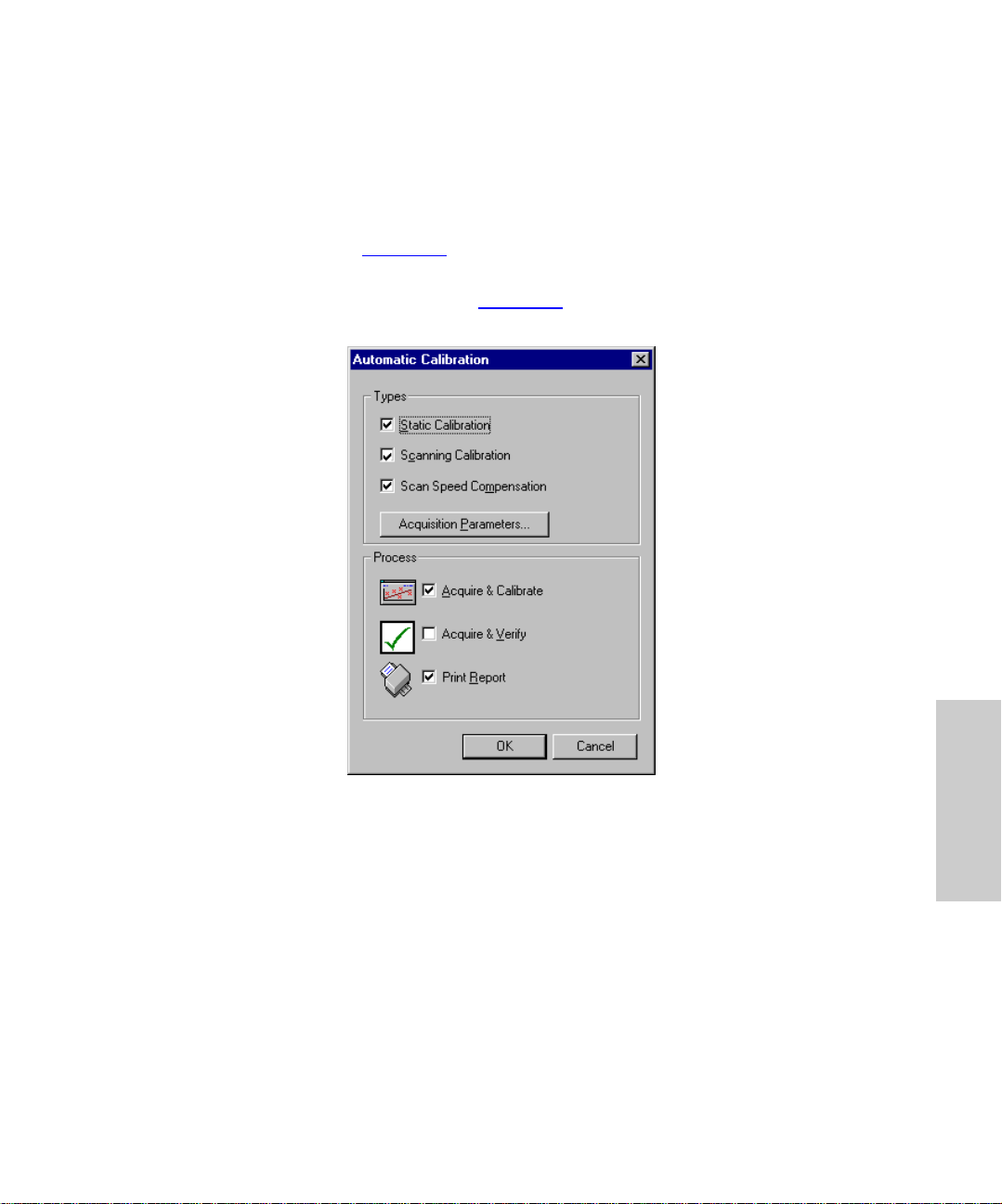
4.2.6 Automatic Calibration Dialog Box
You should perform all three types of calibration: static, scanning, and scan speed
compensation. This lets you subsequently use any data acquisition mode. It also lets you
change mass ranges and scan speeds while maintaining correct mass assignment .
1. Select Calibratio n > C a librat e In strume nt from the Tune window. The Calibration
window appears (Figure 4-1
2. Select Calibrate > Start Acquisition from the Calibration window. The Automatic
Calibration dialog box appears (F igure 4-9
).
).
Figure 4-9 Automatic Calibration Dialog Box
3. Specify the type or types of calibration you intend to perform: Static, Scanning,
and/or Scan Speed.
For a complete calibration, select
Note:
and
Scan Speed Compensation
select
Acquire & Calibrate
and
Print Report
Static Calibration, Scanning Calibration
in t he Types area. Then, in the Process area,
.
Considerations
Though Waters suggests you perform all three types of calibration, you can nevertheless
specify one, or any combination, of calibration types. Beware, however, that doing so
invokes the fol lo wing limitations:
• Specify Static to calibrate only for acquisitions where the quadrupole “parks” at a
single mass (for example, SIR acquisitions).
Calibrating 63
4
,
Page 64

• Specify Scanning to calibrate only for scanning acquisitions. This limits acquisitions
to the same mass range and scan speed you specified in the calibration.
• Specify Scan Speed Compensation to calibrate only for scanning acquisitions over
the same mass range and at the same scan speed you specified in the calibration.
Thus to correctly calibrate for scan speed compensation, you must also perform a
scanning calibration.
• Specify both Static and Scan Speed Compen sation to calibrate for acquisitions
where the quadrupole “parks” at a single mass. Also, provided you specify the same
scan speed, this calibrates for scanning acquisitions whose mass ranges lie within
the scanning calibration’s mass ranges. Accordingly, when you specify a 2-second
scan (400 amu/sec) calibration from 100 to 900 m/z, the instrument can acquire data
from 100 to 500 amu for a 1-second scan (also 400 amu/sec) and maintain correct
mass assignment. In this case the static calibration would determine the acquisition’s
start mass and the scanning calibration the mass assignment and scan range.
• Specify both Scanning Calibration and Scan Speed Compensation to calibrate for
scanning acquisitions over the mass range you specify for the calibration. You can,
however, change the scan speed, provided it remains within the scan speeds you
specified in the two calibrations. In this case do not change the mass range, because
no static calibration exists to locate the start mass.
• Specify all three types of calibration, Static , Scanning, and Scan Speed
Compensation, to allow all types of acquisitions, provided the mass range and scan
speed fall between the lower and upper limits f or scanning calibration and scan speed
compensation.
4.2.7 Calibration Acquisition Dialog Box
Specify mass ranges, scan speeds and acquisition mode in this dialog box, which, when
you first open it, contains default parameter values for the specified reference file. These
values represent the scan range and speed limits of the parameters and instrument.
For improved calibration performance, Waters suggests you adopt the parameter
Note:
values in Table 4-1
Click Acquisition Parameters in the Automatic Calibration dialog box (Figure 4-9
the Calibration Acquisition Setup dialog box (Figure 4-10
.
4
) to open
).
Setting Calibration Parameters 64
Page 65
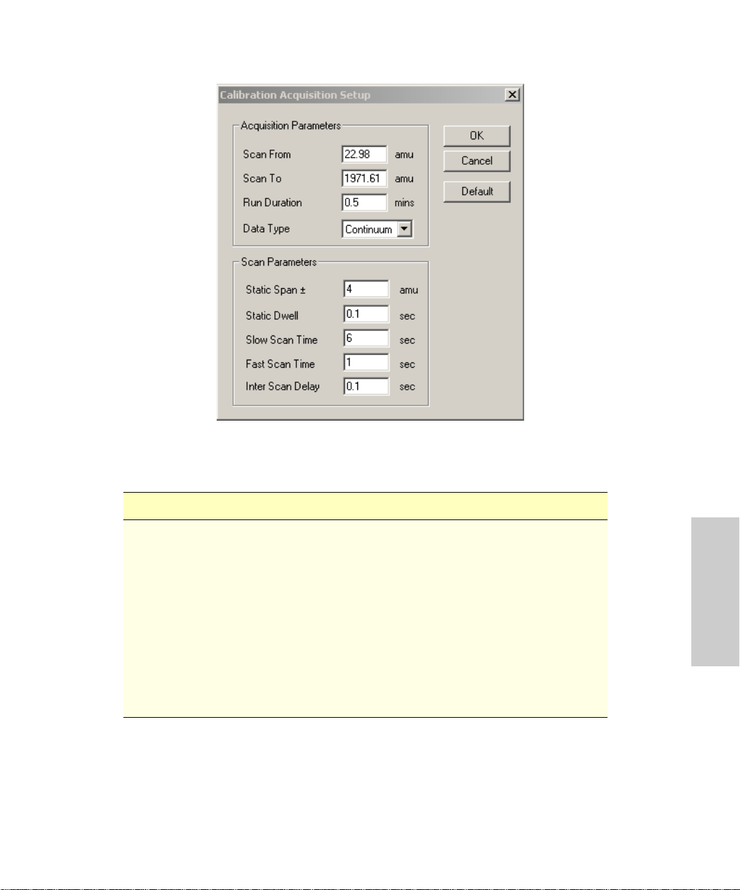
Figure 4-10 Calibration Acquisition Setup Dialog Box
Table 4-1 Recommended Calibration Acquisitions Setup Parameters
Parameter ZQ 2000 ZQ 4000
Scan From (amu) 50 50
Scan To (amu) 2040 4080
Run Duration (mins) 1.0 2.0
Data Type Continuum Continuum
Static Span ± (amu) 4 4
Static Dwell (sec) 0.1 0.1
Slow Scan Time (sec) 10 20
Fast Scan Time (sec) 0.40 0.90
Inter Scan Delay (sec) 0.1 0. 1
4
Calibrating 65
Page 66

Parameters
Scan From, Scan To – Specifies the scan range for each calibration type.
Run Duration – Specifies how much time the instrument takes to acquire each calibration
data file.
Data Type – Specifies data type as centroid, continuum, or MCA. Waters suggests using
continuum or MCA acquisitions for electrospray calibrations.
Calibrating in MCA mode limits maximum acquisition speed to 400 da/sec.
Note:
Static Span – Specifies how much of the mass scale on either side of a reference peak
the instrument scans.
Static Dwell – Specifies the time the instrument takes to scan the static span.
Slow Scan Time – Specifies how much time it takes the instrument to scan the mass
scale over the selected range when acquiring data for scanning calibrations (see next
section for details).
Fast Scan Time – Specifies how much time it takes the instrument to scan the mass
scale over the selected range when acquiring data for scan speed calibrations (see
next section for details).
Inter Scan Delay – Specifies how much tim e el apses between the end of one scan and
the beginning of another.
Main – Resets all parameters to their default values.
About Establishing Scan Speeds
Table 4-1 shows Waters’ recommended parameter settings for using sodium cesium
iodide as the calibrant. However, if you do not calibrate with sodium cesium iodide, you
might need to derive your own scan speed parameter values.
To determine Slow Scan Speed and Fast Scan Speed parameter values, fir st decide what
scan speed range to acquire your sample data within. Do this by applying the following
equation twice, once to establish the range’s lower limit and once to establish its upper
limit:
Scan speed = Scanning range / Scan time + Interscan delay
These calculations use the ZQ 2000 parameter values in Table 4-1
Note:
Use Slow Scan Time to calculate the slowest scan speed a calibration can accommodate
(the range’s lower limit). Thus, where Slow Scan Time = 10 seconds:
Scan speed = (2040 - 50)/(10 + 0.1) = 197 amu/sec
Setting Calibration Parameters 66
.
4
Page 67

Use Fast Scan Time to calculate the fastest scan speed the calibration can accommodate
(the range’s upper limit). Thus, where Fast Scan Time = 0.4 seconds:
Scan speed = 2040 – 50/0.4+0.1 = 3980 amu/sec
The scan speed range for this calibration is 197 to 3980 amu/sec.
Checking the Calibration
Select Process > V er if i cat io n Fr om Fi le from the Calibration window (Figure 4-1) to view
a successful or failed calibration. The Display Calibration Graphs dialog box appears
(Figure 4-11
calibration selected, MassLynx automatically displays the correct calibration file.
). From it you can select a calibration type for viewing. With the required
Figure 4-11 Display Calibration Graphs Dialog Box
Data for the selected calibration type must appear in the lower frame of the dialog
Note:
box. If it does not, click
Click OK to repeat the calibration and display a Calibration report.
Browse
to find the correct file.
Calibration Report
MassLynx momentarily displays a successful calibration and then prints its Calibration
report. However, if the standard deviation of a calibration’s residuals exceeds the preset
maximum, the software displays a set of calibration graphs in the Calibration window
(Figure 4-12
). These help you identify the problem.
Calibrating 67
4
Page 68

The top calibration graph shows the calibration file. The peak-matching algorithm, which
matches calibration peaks to reference peaks, shows the peaks in a contrasting color.
The Data and Reference file graphs show the calibration spectrum with its highlighted
peaks matched with reference peaks of a contrasting color . Other graphs show mass
difference and residuals.
Updating the Calibration Report
1. Select Edit > Calibration Parameters from the Calibration window. The Calibration
Parameters dialog box appears (Figure 4-7
2. Enter changes, and click OK.
Printing the Calibration Report
).
1. Click the Calibration window (Figure 4-1
2. Click Yes to save changes in the calibration file. The Save As dialog box appears.
3. Enter a file name in the File name field.
Waters recommends you incorporate the current date in every file you name.
Note:
4. Click Save or Cancel. The Automatic Calibration dialog box appears (Figure 4-9
5. Select Scan Speed Compensation as the calibration type.
6. Select Acquire & Calibrate and Acquire & Verify as the process methods.
7. Select Print R eport , and click OK. The Calibrate window appears displaying
calibration graphs (Figure 4-12
8. Che ck the Mean Residual Error parameter, which must be equal to or less than ±
0.2 for a calibration to be successful.
).
) to activate it.
).
4
Setting Calibration Parameters 68
Page 69

Mean Residual
Error
Figure 4-12 Calibrate Window Showing ZQ-4000 Calibration Graphs
Calibration Failure
Calibration failures result from many causes. If too many mass peaks are missed, check
data in the on-screen Calibration report. If the missed masses appear there, one or more
of the first three causes listed in Table 4-2
peaks, but they nevertheless go unrecognized during calibration, one or more of the
subsequently listed causes probably induced the failure.
Table 4-2 Calibration Failure Troubleshooting
Symptom Possible Cause Corrective Action
No peaks. No reference sample. Add reference s ample.
No solvent flow into the
source.
Multip lie r se t too low. Adjust mult ip lier.
likely apply. If the data include these mass
Check LC components,
syringe pump, and liquid
line connections.
4
Calibrating 69
Page 70

Table 4-2 Calibration Failure Troubleshooting (Continued)
Symptom Possible Cause Corrective Action
Too many consecutive
peaks missed.
Having taken the necessary action, proceed as follows:
1. If the values in the Intensity threshold, Initial error, and Peak windows are adjusted
to obtain a successful calibration, check the on-screen Calibration report to ensure
the correct masses have been matched.
2. Click OK in the Calibrate window to accept the new calibration, or click Cancel to
keep the previous calibration.
Reference solution in low
supply or concentration.
Mul ti plier set too low to d e tect
the less intense peaks.
Incorrect ionization mode
selected.
Intensity threshold too high. Lower threshold, or
Initial Error and/or Peak
Window parameter set too low.
Maximum Std Deviation
exceeded.
The wrong reference file has
been selected.
Increase reference solution or its concentration.
Res e t the Multiplie r
parameter.
Make sure the ionization
mode matches the calibration file.
increase reference
concentration.
Increase parameter limits.
Widen (increase) the
Maximum Std Deviation
parameter.
Select the appropriate
reference file.
Incorrect Calibr ation
The instrument can sometimes meet the calibration criteria, despite failing to match the
correct peaks. Such error can arise when you specify these settings:
• Intensity threshold set to 0
• Initial error greater than 2.0
• Peak window greater than 1.5
• Maximum Std Deviation greater than 0.2
Always examine the on-screen Calibration report (Figure 4-12
The calibration is correct when the acquired spectrum looks like the reference spectrum,
and it highlights all the expected peaks.
Setting Calibration Parameters 70
) for correct peak matches.
4
Page 71

Contamination or background peaks can also invalidate a calibration. For example, a
contamination or background peak that lies within a peak-matching window might be more
intense than its neighboring reference peak. Thus the software can choose the
contamination or background peak instead of the reference peak. In such a case, if the
reference peak is closer to the peak window’s center, narrow the peak window to exclude
the con tamin a t i o n o r b a ck gr o u nd peak. If, on the o ther hand, the reference peak is not
closer to the window’s center, and you cannot narrow the window without affecting it, edit
the calibration manually.
Manually Editing Matched Peaks
You can manually exclude incorrectly matched peaks from the on-screen Calibration
report. Manual ly editing a sin gle peak w ill not affect other matched peaks in th e
calibration.
To exclude an incorrectly matched peak in an acquired spectrum, place the cursor over it
and right-click. This removes the peak’s highlighting and excludes it from reported data.
To include a peak as a reference, place the cursor over it and right-click. This matches the
selected peak to the closest peak in the reference spectrum.
Saving the Calibration
You can save and reuse calibrations.
Mass range and scan speed limits remain unchanged for retained calibrations. So do ion
energy and resolution settings for calibration acquisition, which can affect mass
assignment.
V er ifyin g the Calibrati on
Once you perform and save a full instrument calibration, repeating it is not always
necessary. Instead, you can make a scanning acquisition and verify a saved calibration,
following this procedure:
1. Open the Calibration Parameters dialog box by selecting Edit > Calibration
Parameters from the Calibration window (Figure 4-1
2. Set all peak matching parameters to those used in the calibration.
3. Select Calibrate > Start Acquisition from the Calibration dialog box (Figure 4-1
open the Automatic Calibration dialog box (Figure 4-9
4. Enable these parameter fields in the Automatic Calibration dialog box:
• Scanning Calibration
•Acquire & Verify
• Print Report
5. Disa ble these parameter fields:
• Stat i c Calibra tion
).
).
Calibrating 71
4
) to
Page 72

• Scan Speed Compensation
• Acquire & Calibrate
6. Click the Acquis ition Par a meters button to open the Calibration Acquisition Setup
dialog box (Figure 4-10
7. Set Scan From, Scan To, Run Duration, Data Type, Slow Scan Time, Fast Scan
Time, and Inter Scan Delay to agree with the parameters you will use for data
acquisition.
No other options apply when you select Scanning Calibration.
Note:
8. Click OK. The Automatic Calibration dialog box reappears.
9. Click OK to start the verification procedure.
The instrument performs a scanning acquisition. Then MassLynx combines the data
acquired into a single spectrum, which it compares with the reference file. MassLynx then
creates and prints a calibration curve. Unlike the original calibration procedure, the
instrument’s calibration remains unchanged, the printed report serv i ng as verification.
Do not adjust analyser settings (LM, HM resolution, and ion energy) after
Note:
calibrating. Use only source parameters to optimize signal intensity.
).
Setting Calibration Parameters 72
4
Page 73

Chapter 5 Maintaining
This chapter includes routine maintenance procedures.
5.1 Considerations
Safety and Handling
Observe good laboratory practice when you handle solvents, change tubing, or
Do not touch integrated circuit chips or other circuit board components that do
Never open the instrument’s top or side panels to access power supplies or
Never disconnect an electrical assembly while the system is plugged in. This
Also, turn off the power and wait 10 seconds before disconnecting an
STOP
STOP
STOP
Caution:
operate the instrument. Refer to Material Safety Data Sheets for the solvents you use,
and know their chemical properties.
Attention:
not specifically require manual adjustment. Static electric charge can damage electr onic
components.
Attention:
other components. The supplies do not contain user-serviceable parts.
Attention:
could damage electrical parts.
Attention:
assembly.
Maintenance Equipment
Routine parts cleaning requires the following equipment:
• An ultrasonic bath with a minimum chamber size of 12 in. × 6 in. × 4 in. (300 mm ×
150 mm × 100 mm)
• Glass vessels, approximately 4 in. (100 mm) in diameter and 4 3/4 in. (120 mm) high
• A 500-mL graduated cylinder (to use when cleaning the hexapole assembly)
Considerations 73
5
Page 74

Contacting Waters Technical Service
North American customers who experience maintenance problems they cannot resolve
should contact Waters Technical Service at 800 252-4752. Others should phone their local
Waters subsidiary or Waters corporate headquarters in Milford, Massachusetts (U.S.A.).
Table 5-1
instrument’s optimal performance.
Note:
moderate use.
Table 5-1 Maintenance Schedule
Gas-ballast the rotary pum p. Daily (APC I )
Check the rotary pump oil, and top-off when
necessary.
Replace the rotary pum p oil. Every 3 months of continuous
Clean the cone gas nozzle, sample cone, and
baffle plate.
Clean the ESI APCI probe tip, or replace the ESI
capillary.
Replace the APCI fused silica.
Clean the corona discharge needle (APCI mode). When sensitivity decreases to
lists periodic maintenance schedules you should observe to ensure the
The maintenance frequencies shown apply to instruments that normally receive
Maintenance Procedure Frequency
Weekly (ESI)
Weekly
operation, or whenever the oil
appears markedly discolored
When sensitivity decreases to
unacc e ptable levels
When sensitivity decreases to
unacc e ptable levels
unacc e ptable levels
Clean the ion block assembly. When it is visibly fouled
When background or peak
contaminants are unaccept- ably
high
Clean all source components. When sensitivity decreases to
unacc e ptable levels
When cleaning the cone gas
nozzle, sample cone, and baffle
plate fails to improve results
Maintaining 74
5
Page 75

5.2 Routine Maintenance
Routine maintenance comprises these tasks:
• Checking the rotary pump oil (Section 5.2.1
• Changing the pump oil (Section 5.2.2
• Gas-ballasting the rotary pump (Section 5.2.3
• Replacing the oil mist filter (Section 5.2.4
• Cleaning the source assembly (Section 5.2.5
• Cleaning the APCI probe tip (Section 5.2.6
• Cleaning and replacing the corona discharge needle (Section 5.2.7
Perform routine maintenance at scheduled intervals (Table 5-1
indicates it is necessary.
5.2.1 Checking the Rotary Pump Oil
You can check the oil level while the pump is operating.
Note:
The rotary pump oil level appears in the rotary pump’s oil level sight glass. Check the oil
lev el at weekly intervals. Maintain it at or near the MAX level . If y ou must add oil, vent and
shut down the d etector before rem oving the oil filler p lug.
Examine the oil each time you check its level. It should be colorless, free of visible
contaminants. If it is discolored, change it, following the procedure in Section 5.2.2
5.2.2 Replacing the Pump Oil
)
)
)
)
)
)
)
), or when troubleshooting
.
You must vent the instrument and shut it down before adding oil.
Note:
Change the rotary pump oil after every 3 months of continuous operation, or whenever it
becomes markedly discolored. Gas-ballast following every oil change.
Required Materials
• Latex or vinyl gloves
• Flat-head screwdriver
• Container to catch used oil
• Funnel
• Vacuum oil (use only Ultragrade 19 or Inland Q45 (Edwards 45) vacuum pump oil)
• 4-mm hex wrench
Routine Maintenance 75
5
Page 76
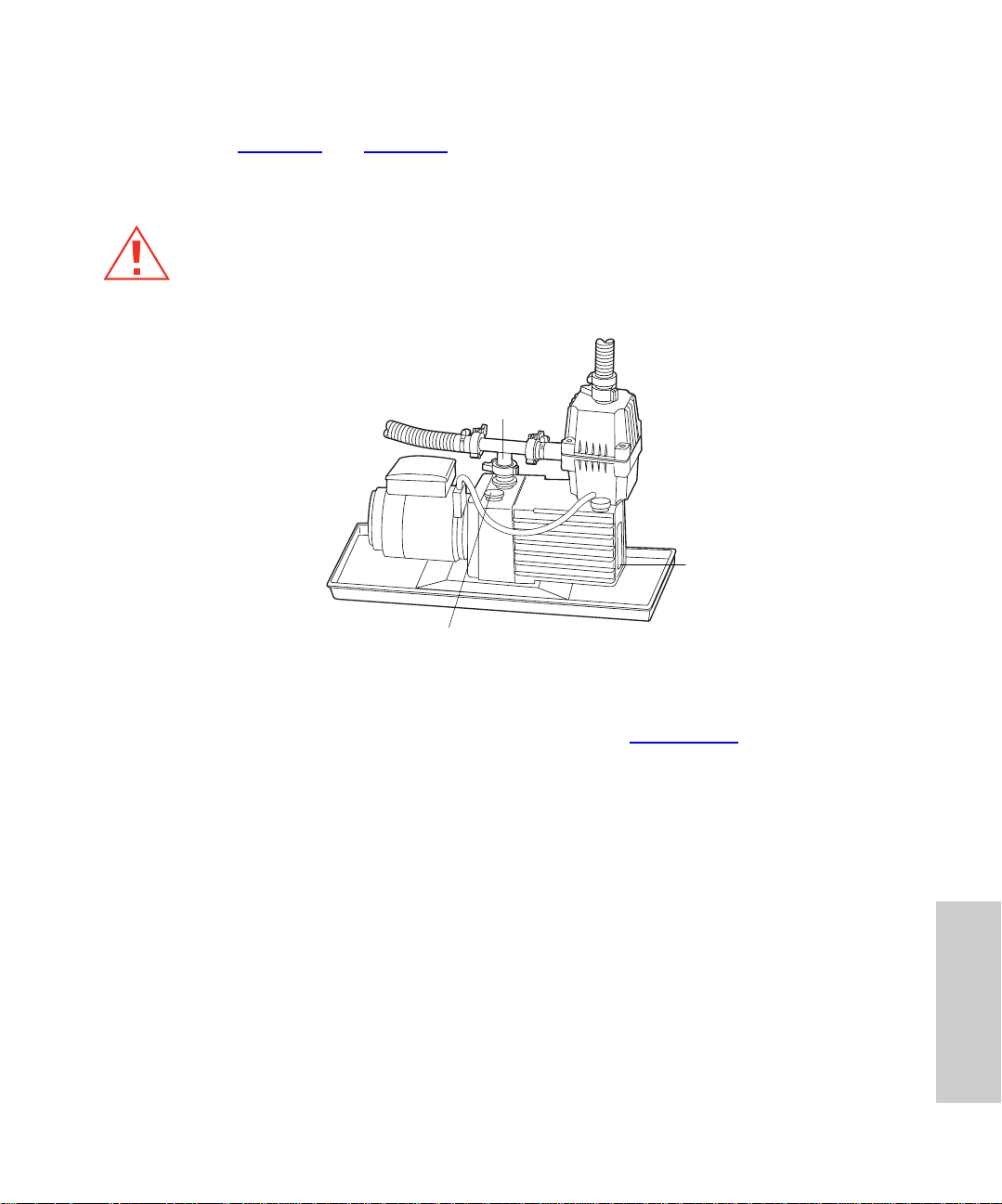
Procedure
Refer to Figure 5-1 and Figure 5-2 when performing the following procedure.
Operate the pump to warm the oil before you drain it.
Note:
Caution:
Note:
these steps.
Wear latex or vinyl gloves when changing the pump oil.
NW25 Inlet
Gas Balla s t Con t ro l
Figure 5-1 Rotary Pump Assem bly Fitted with Oil Mist Filter
Vent the instrument according to the procedure in Section 5.2.5
Oil Mist F ilt er
Drain Plug
TP02004
, and proceed with
1. Turn the instrument’s power switch to Off.
2. Place something under the pump motor, tilting the unit so that the oil drain plug is at
the lower end.
Maintaining 76
5
Page 77
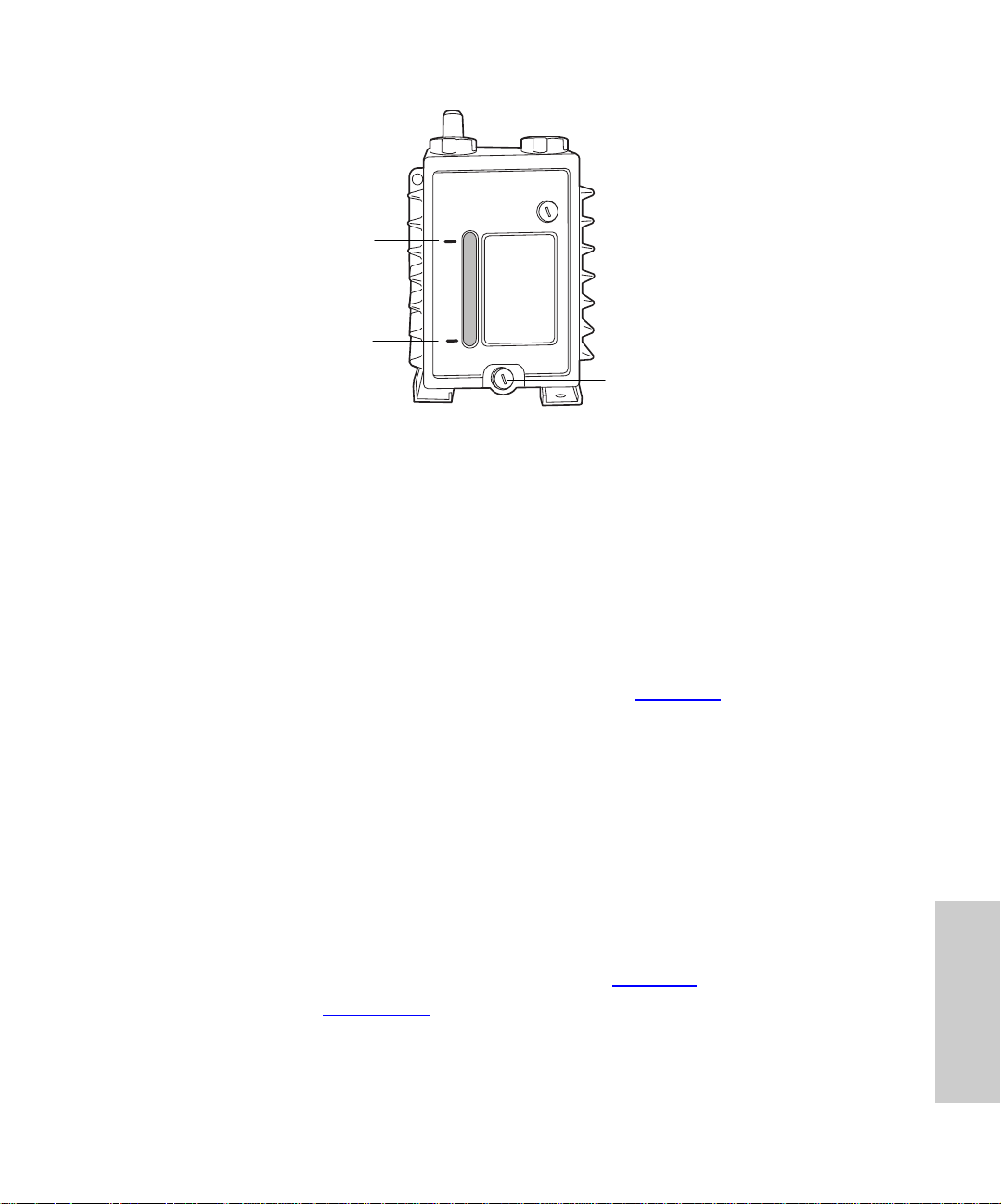
Oil Fi ller Plug
MAX
MIN
Drain Plug
Figure 5-2 Rotary Pump Oil Filler Plug, Drain Plug, and Sight Glass
3. Remove the drain plug with the slotted screwdriver.
4. Remove the oil filler plug to facilitate drainage.
5. Drain the oil completely.
6. Flush res idual oil from the pump as follows:
a. Refit the oil drain plug.
b. Add about 300 mL of oil to fill the pump to the MIN mark on the sight glass.
c. Refit the oil filler plug.
d. Select Options > Pum p from the Tune window (Figure 3-3
operating. Continue to run the pump for 10 to 15 minutes.
e. Select Options > Vent and click Yes at the prompt to stop the pump.
f. Let the oil drain completely.
7. Use a funnel to add about 1 L of oil to the pump, until the level in the sight glass
reaches the MAX mark.
8. Allow a few minutes for the oil to fully drain to the bottom of the pump, then recheck
the level. Add more, if necessary, but do not overfill.
) to start the pump
The oil level norma lly drops about 10% after the pump starts.
Note:
9. Refit the oil filler plug.
10. Select Options > Pump from the Tune window (Figure 3-3
11. Gas-ballast (Section 5.2.3
).
Routine Maintenance 77
) to start the pump.
5
Page 78

5.2.3 Gas-Ballasting the Rotary Pump
The rotary pump draws large quantities of solvent vapors. The vapors tend to condense in
the pump oil, diminishing pumping efficiency. Gas-ballasting purges condensed
contaminants from the oil.
Gas-ballast the rotary pump when these conditions apply:
• With ESI operation, once a week
• With frequent APCI operation, once a day
• When the pump oil appears cloudy
• When the vacuum pressure is higher than normal
• When condensate forms in the rotary pump exhaust line
• When you change the rotary pump oil
STOP
STOP
STOP
Attention:
consequently, pump life.
Attention:
Attention:
1. Shut the vacuum system isolation valve, moving its handle fully to the right
Failure to routinely gas-ballast the rotar y pump shortens oil life and,
Do not vent the instrument when the rotary pump is gas-ballasting.
Do not gas-ballast the rotary pump while the detector is in operational mode.
(Figure 5-1
).
Attention:
Never gas-ballast the rotary pump for more than 2 hours.
STOP
2. W hen the oil is clear, return the gas-ballast control to its normal position.
3. Open the vacuum system isolation valve (Figure 5-3
).
Maintaining 78
5
Page 79
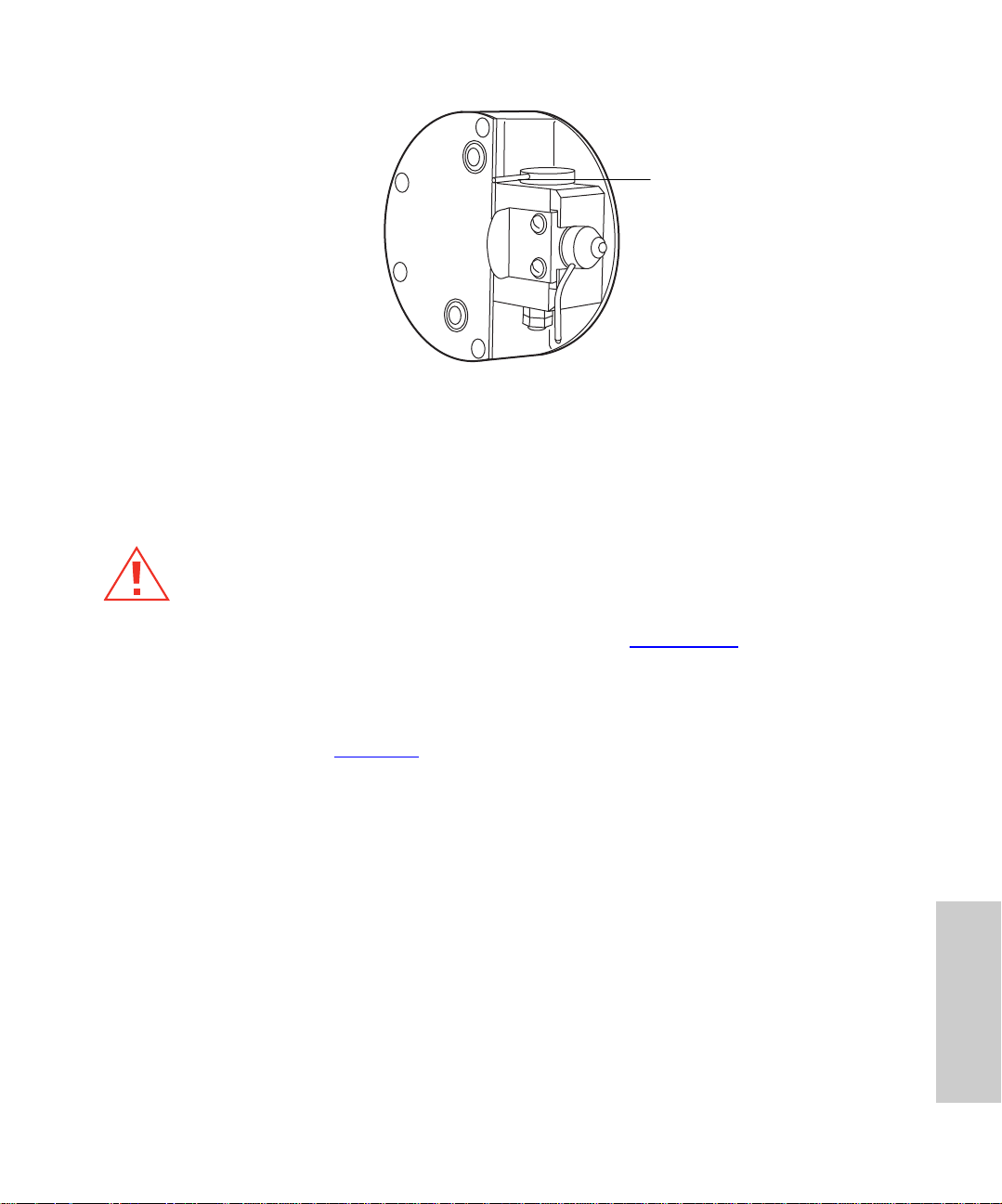
Figure 5-3 Isolation Valve
4. O pen the gas ballast knob on the top of the pump. Run the pump for 30 to 60
minutes, then close the gas ballast knob.
5.2.4 Replacing the Oil Mist Filter
Isolation Valve (Open)
Caution:
Note:
these steps.
1. Turn the instrum ent’s power swi tch to Off.
2. Unscrew the NW25 clamp, and remove the exhaust line from the top of the oil mist
3. Lo osen the four bolts that secure the top and bottom covers of the oil mist housing
Wear latex or vinyl gloves when replacing the oil mist filter.
Vent the instrument according to the procedure in Section 5.2.5
filter housing (Figure 5-4).
with a 4-mm hex wrench.
, and proceed with
5
Routine Maintenance 79
Page 80

Oil Mist F ilt er Hou s in g
Oil Mist
Filter Element
Figure 5-4 Oil Mist Filter Assembly
4. Remove the top cover, and discard the odor filter.
The odor filter will likely stick to the cover.
Note:
5. Pull upward on the oil mist filter, removing and discarding it along with its O-ring.
6. Slip the new O-ring over the support post in the bottom of the filter housing, then
press the new oil mist filter on top.
7. Refit the top cover, securing it with the four screws.
8. Rea ttach the exhaust hose to the NW25 clamp.
9. Evacuate the system by selecting Options > Pump from the Tune window.
5.2.5 Cleaning the Source Assembly
Clean the sample cone and cone gas nozzle when they are visibly fouled, or when you
eliminate LC and sample-related causes for decreased signal intensity. When cleani ng
these parts fails to increase signal sensitivity, also clean the extraction lens, hexapole, and
ion block.
Required Materials
• Lint-free cotton or powder-free nitrile gloves
• 6-in. forceps or needle-nose pliers
• 2.5-mm hex wrench
• 3-mm hex wrench
• 6 mm-hex wrench
5
Maintaining 80
Page 81

• Small, flat-head screwdriver
• Small, Phillips-head screwdriver
• Clean, 1000-mL beaker
• Clean, 500-mL graduated cylinder
Use only glassware you have not cleaned with surfactants.
Note:
• HPLC-grade methanol
• HPLC-grade water
• Formic acid
• Ultrasonic bath
• Source of oil-free, inert gas (nitrogen or helium) for drying (air-drying optional)
• Lint-free paper towels
Spare Parts
You might need to replace these spare part s when cleaning sourc e compone nts.
Item Waters P ar t N um be r Reference Number
Ion block D-ring (AS035) 700001192 5711312
Viton O-ring (AS214) 700000902 5711294
Extraction cone O-ring 700001897 5711967
Sample cone O-ring 700001194 5711321
Source Cleaning Procedure
1. Disassemble the source components (see “Disassembling Source Components” on
page 82).
2. Clean the source component s (see “
88).
3. Remove and clean the hexapole assembly (see “
Hexapole Assembly” on page 89).
4. Reassemble the source components (see “
on page 90).
Cleaning the Source Components” on page
Removing and Cleaning the
Reassembling the Source Components”
Routine Maintenance 81
5
Page 82
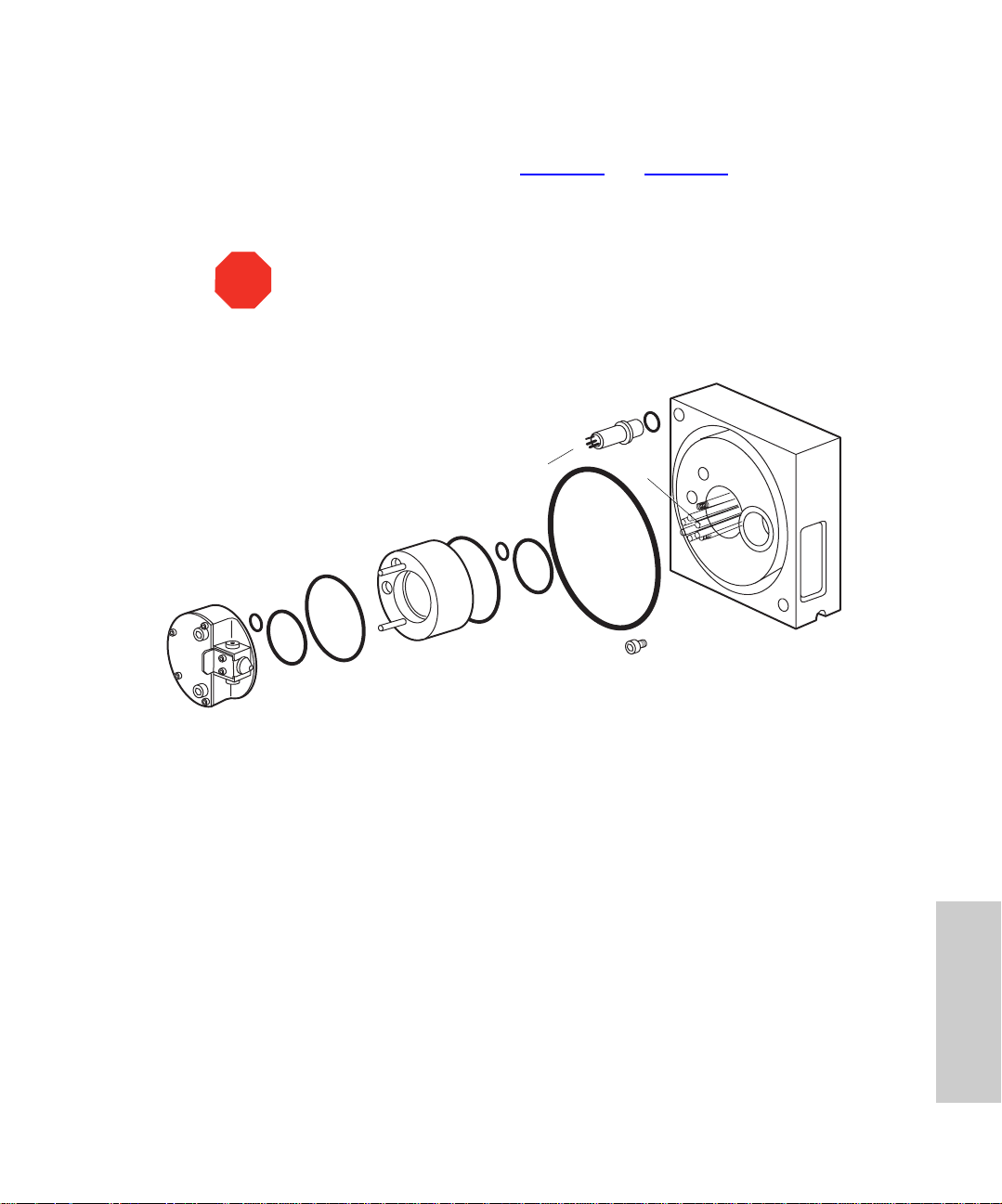
Disassembling Source Components
The source components comprise the pumping block and ion block assemblies, which you
must disassemble before cleaning. Consult Figure 5-5
and assembling these assemblies.
1. Stop the liquid flow, then disconnect the LC line from the probe.
and Figure 5-6 when disassembling
1
STOP
2
Attention:
Never remove either probe before the source heater cools to
below 100 °C and the source heaters cool to below 50 °C. Doing so will
shorten the probe heater life. To reduce cooling time, continue flowing API
gas.
11
10
9
8
5
4
3
7
6
14
12
13
TP02001
1 – Ion Block Assemb ly
2 – O-Ring, Viton (AS016)
3 – O-Ring, Viton (2-030)
4 – Ion Block Support
5 – O-Ring, Viton (2-039)
6 – O-Ring, Viton (AS016)
7 – O-Ring, Viton 42.0 × 1.5 mm
Figure 5-5 Pumping Block Assembly
8 – PTFE Encapsulated O-Ring
9 – Source Pogo Pins
10 – PEEK Connector Body
11 – O-Ring, Viton 2-103
12 – Threaded Plug
13 – Pumping Block
14 – Hexapole
Maintaining 82
5
Page 83

14
15
13
12
11
10
7
5
3
4
4
4
2
1
4
1
6
4
4
4
8
9
16
24
25
26
27
21
17
22
19
20
18
23
TP02000
1 – Ion Block Fastener
2 – BS 10 Black Viton O-Ring
20 Cross
3 – Screws, M3
×
4 – M3
Washer, M3 SS
5 –
6 – Cover Plate
7 – Heater Assy
8 – O-Ring, Viton, 2-035
9 – Cone Gas Spring Clip
10 – Terminal Block
11 – Ion Block Plug
12 – Ion Block Plug Seal
13 – Ion Block
14 – Valve Stem
×
6 PH
15 – Large Valve Stem Washer
0.063
16 – O-Ring, Kalrez, 0.240
17 – Seal Ring
18 – Black Viton O-ring PTFE Encapsulated
19 – Extraction Retainer
20 – Extraction Cone
21 – Sample Cone O-Ring
22 – Sample Cone
23 – Cone Gas Nozzle
24 – O-Ring, Kalrez, AS007
25 – Small Valve St em Washer
26 – Flat Washer, M4
27 – Metric Hex Nut, M4
×
Figure 5-6 Ion Block Assembly
2. Click Press For Standby on the Tune window . The icon changes from green to red.
This means all high voltages are turned off, as well as the ESI desolvation /APCI
probe heater.
3. Switc h off the source heater by setting a temperature of 20 °C and pressing Enter.
4. Before you remove the ESI or APCI probe, stop the nitrogen flow by toggling
on the toolbar to Off.
5. Select Options > Vent and Yes, at the prompt. Click OK when the message box
appears.
5
Routine Maintenance 83
Page 84

Attention:
STOP
Note:
the pump continues to operate briefly, until rotational speed decreases to less than
50%, at which point its vent valve opens.
6. Disconnect the appropriate front panel gas and electrical connections.
7. Unscrew the probe’s two knurled thumbscrews, and retract it from the source
(Figure 5-7
need not vent the system.
Venting interrupts electrical power to the turbomolecular pump. Nev ertheless,
)
If you are cleaning only the sample and cone gas nozzles, you
STOP
Caution:
Attention:
source heater cools to below 50 °C. Doing so shortens the life of the probe
heater. To reduce cooling time, continue flowing API gas.
Source
The probe might be too hot to handle. Allow time for it to cool.
Never remove a probe before it cools to below 100 °C and the
Thumbscrew
Source Enclosure Cover
Clip
Fastener
Figure 5-7 Probe Assembly in Position on the Source
Clip
Fastener
5
Maintaining 84
Page 85

8. Remove the center panel (Figure 5-8) from the front of the instrument by grasping its
sides and pulling it toward you.
Removable
Center Panel
Figure 5-8 ZQ Detector Front View
9. Unfasten the two clip fasteners (Figure 5-7
downward on its hinge, allowing access to the source contents.
Attention:
STOP
10. I f you are using an APCI probe, carefully remove the corona discharge needle
(Figure 5-9
the cleaning procedure.
).
Wear lint-free cotton or powder-free nitrile gloves for the rest of
) so that the source enclosure opens
Routine Maintenance 85
5
Page 86

e
t
Pumping Block
Ion Block
Corona Pin
Mounting Contac
Corona Discharg
Needle
PTFE Tubing
Figure 5-9 Source Showing the Corona Discharge Needle
11. Remove the PTFE tubing attached to the cone gas nozzle (Figure 5-10
6-mm Hex Screw
Isolation Valve
Cone Gas
Spri ng C lip
6-mm Hex Screw
PTFE Tubing
Figure 5-10 Ion Block
Maintaining 86
).
5
Page 87
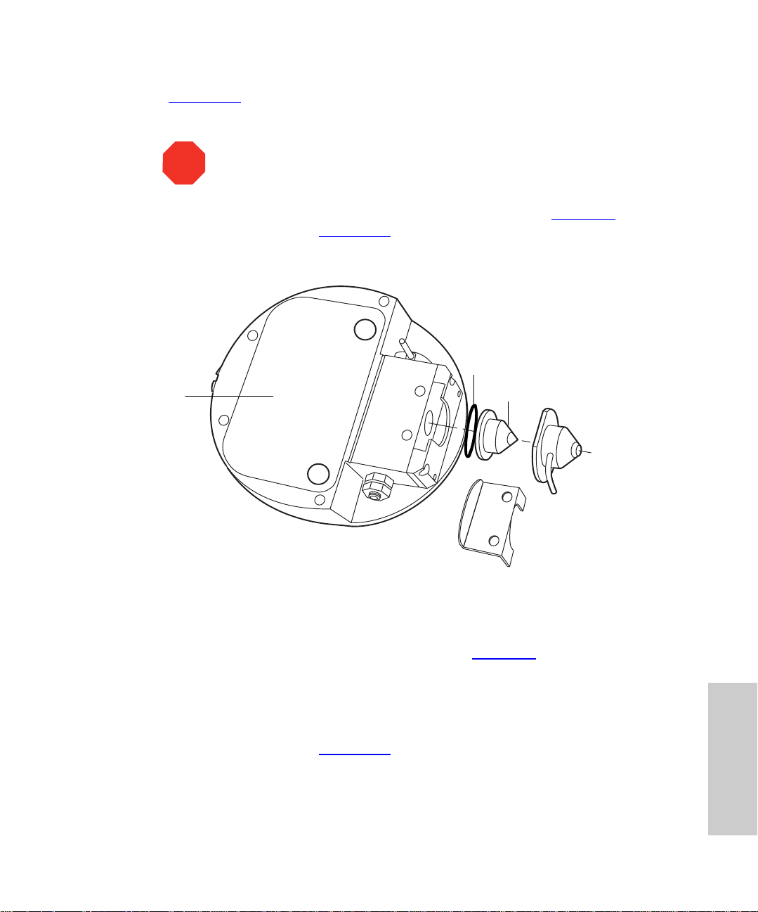
12. Rem ove the two 2.5-mm hex screws securing the cone gas spring clip
(Figure 5-10
13. Remove the cone gas nozzle, O-ring, and sample cone from the ion block.
).
Attention:
Do not scratch the highly polished cone orifice surfaces.
STOP
14. Carefully separate the sample cone from the cone gas nozzle (Figure 5-6
the sample cone O-ring (Figure 5-11
15. R em ove the baffle plate, and set all pieces aside.
Ion Block
).
Sample Cone O-Ring
Sample Cone
Cone Gas Nozzle
Cone Gas Spring
Clip
). Remove
Figure 5-11 Sample Cone and Cone Gas Nozzle
16. Rem ove the two 6-mm hex screws that secure the ion block.
17. R em ove the ion block from the ion block support (Figure 5-5
snugly on the support, so separating them can require considerable effort.
18. Place the ion block on a flat surface , and remove any remaining O-rings that remain
on it.
19. Use th e P h i llip s - he ad screwdriver to re move the ho ld- d ow n scr ew from the PEEK
extraction cone retainer (Figure 5-12
).
). The ion block fits
Routine Maintenance 87
5
Page 88
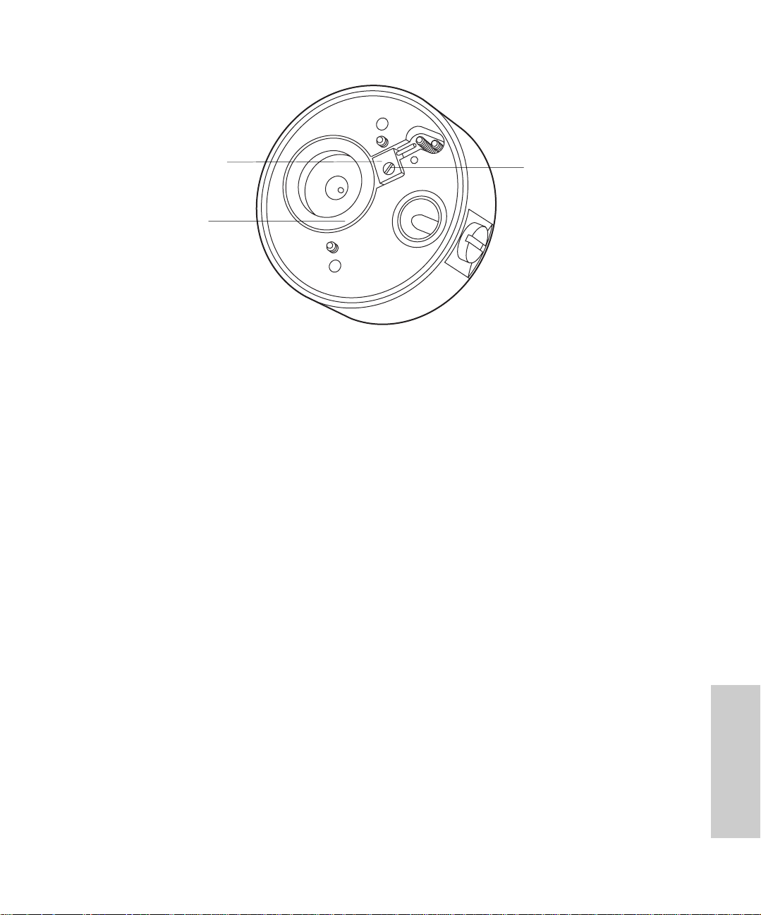
Extraction
Retainer (PEEK)
Extracti on Cone
Figure 5-12 Ion Block Rear View
Do not damage t he ion block surface and insulator O-rin g.
Note:
20. Grasp the extraction cone pin with the needle-nose pliers. Lift the e xtraction cone
from the ion block.
21. I nsert a suitable nonmetallic implement under the inner edge of the polymeric seal
ring to pry the seal ring and O-ring out of the ion block.
Avoid damaging the seal and O-ring on the ion block.
Note:
22. Remove the D-shaped O-ring from the front of the ion block.
Hold-Do w n Screw
Cleaning the Source Components
1. Place the ion block in a beaker with methanol : water (1:1).
2. Place the beaker containing the ion block and methanol/water mixture in an
ultrasonic bath for 20 minutes.
3. Remove the ion block from the methanol/water mixture, and place it in a beaker
containing 100% methanol.
4. Place the sample cone, cone gas nozzle, and extraction cone in a beaker containing
methanol : water (1:1). If debris have accumulated at the sample cone orifice, place
a drop of formic acid on the orifice before placing it in the beaker.
If the parts are obviously fouled, use a mixture of 45% methanol, 45% water,
Note:
and 10% formic acid.
Maintaining 88
5
Page 89

Caution:
hood and appropriate protective equipment.
5. Expos e all parts to ultrasound for about 30 minutes. If you used formi c acid in the
cleaning solution, rinse the par ts well, immersing them in a beaker of water and
setting the beaker in an ultrasonic bath for about 20 minutes to remove all traces of
the acid. Then displace the water by immersing the parts in a beaker of methanol
and setting the beaker in the ultrasonic bath for 10 minutes.
6. Care fully remove the parts from the beaker. Blow-dry them using inert, oil-free gas.
Alternatively, arrange the parts on lint-free towels and let them air dry . Wipe off water
spots with a lint-free cloth.
Be extremely careful when working with formic acid. Use a fume
Removing and Cleaning the Hexapole Assembly
1. Remove the 3-mm screws securing the ion block support, and remove the ion block
support from the pumping block. Remove any O-rings that remain stuck to the
pumping block surface (Figure 5-5
2. Use your hand to gently grasp the hexapole (Figure 5-13
from the analyser assembly.
).
), and retract it carefully
Alignment Notch
Rear Support Ring
Figure 5-13 Hexapole Assembly
Attention:
STOP
3. Bend a length of stainless steel tubing into a hook shape. Insert the hook into one of
the holes in the assembly’s rear support ring.
4. Carefully suspend the assembly i n a graduated cylinder. Add methanol to the vessel
until it covers the assembly.
5. Place the graduated cylinder in an ultrasonic bath for 30 minutes.
hexapole. Their orientation relative to one another is critical to the
instrument’s performance. Also, avoid scratching the bored surfaces of the
pumping block as you withdraw the hexapole.
Never squeeze the hexapole rods t ogether when you remove the
Routine Maintenance 89
5
Page 90

6. Remove the hexapole assembly from the graduated cylinder, and place it on a
lint-free cloth. Allow it to air-dry, or use a nitrogen flow to dry it.
7. Insert the assembly, aligning the notches in the differential aperture at its rear with
the two bottom support rails on the analyser assembly. Carefully slide the assembly
into place (Figure 5-13
8. Check the condition of the three, rear, ion block support O-rings. Replace them with
new ones, if necessary. Ensure the O-rings are properly installed before reattaching
the ion block support.
The pilot pin in the ion block suppor t must align with the notch on the ion
Note:
block.
9. Secure the ion block by alternately tightening its retaining screws.
). Be sure to insert the assembly fully.
Reassembling the Source Components
1. Visually examine the condition of the three, front, ion block support O-rings
(Figure 5-5
you proceed.
2. Refit the PEEK seal rin g and O-ring on the ion block.
3. Pres s the extraction cone into the ion block support. Secure it with the PEEK
retainer and screw.
4. Refit the sample cone and its O-r ing into the cone gas nozzle. Secure all part s with
the cone gas spring clip and two 2.5-mm hex screws.
5. Refit the ion block assembly to the PEEK support block. Secure it with two 6-mm
hex screws. Avoid overtightenin g.
6. If you have cleaned only the sample and cone gas nozzles, turn the isolation valve
(Figure 5-10
7. If you are using the APCI probe, replace the corona discharge needle
(Section 5.2.7
8. Refit the PTFE tube to the cone gas nozzle.
9. Close the source enclosure, reattaching its clip fasteners.
10. Refit the probe assembly, and reconnect the LC line.
11. Refit the center panel (Figure 5-8
12. Reconnect the front panel gas and electrical lines.
13. Evacuate the instrument, turn on the API gas, and check for nitrogen leaks around
the source enclosure.
). Replace them, if necessary . Be sure they are properly installed before
) back to Open.
).
) on the front of the instrument.
5
Maintaining 90
Page 91

5.2.6 Cleaning the APCI Probe Tip
Clean the APCI probe tip when buffer residue accumulates on the probe tip or when signal
intensity weakens.
1. St op the liquid flow.
2. Open the source enclosure cover, and close the isolation valve (Figure 5-10
the source enclosure cover, reattaching its clip fasteners.
3. Click (API Gas) in the Tune window to star t nitrogen flowing.
4. Adju st the nitrogen flow to approximately 650 liters per hour, as indicated by the
Tune window (Figure 3-3
temperature to 650 °C, and press Enter.
5. Click the Operate icon, and wait 10 minutes with the APCI probe heater at 650 °C.
This will remove any chemical contamination from the probe tip.
) desolvation gas meter. Set the APCI probe heater
5.2.7 Cleaning and Replaci ng the C orona Discharge Needle
Clean or replace the needle if it looks corroded or black, and you have noticed decreased
signal intensity.
Required Materials
• Lint-free cotton or powder-free nitrile gloves
• Lapping film
• HPLC-grade methanol
• Lint-free tissue
). Close
Procedure
To clean and replace the corona discharge needle (Figure 5-9):
1. Remove the center panel from the front of the detector (Figure 5-8
2. Remove the two knurled thumbscrews from the top of the probe.
3. Disconnect the front panel gas and electrical connections (Figure 5-8
4. O pen the source enclosure cover.
Attention:
STOP
5. Remove the corona discharge needle from the source, pulling it straight out.
the cleaning procedure.
Caution:
components are hot.
Wear lint-free cotton or powder-free nitrile gloves for the rest of
The inner surfaces of the source enclosure and its constituent
Routine Maintenance 91
).
).
5
Page 92
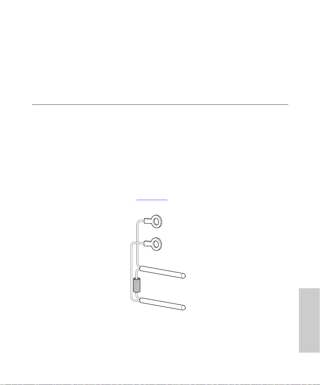
6. Clean and sh arpen the tip of the needle with the lapping film, then wipe the needle
clean with a methanol-saturated tissue. Replace the needle if it is deformed or
otherwise damaged.
7. Reins tall the needle. Point the tip toward the sample cone.
8. Clos e the source enclosure cover, reattaching its clip fasteners.
9. Reins tall the probe assembly.
5.3 Replacing Parts
5.3.1 Replacing the Ion Block Cartridge Heater
Replace the cartridge heat er when it fails to heat.
Required Materials and Spare Part
• 3-mm hex wrench
• 1.5-mm hex wrench
• Slotted screwdriver
• Needle-nose pliers
• Ion block cartridge heater (Figure 5-11
reference number M955504AD1)
), spare part (par t number 700001201,
Figure 5-14 Ion Block Cartridge Heater
5
Maintaining 92
Page 93
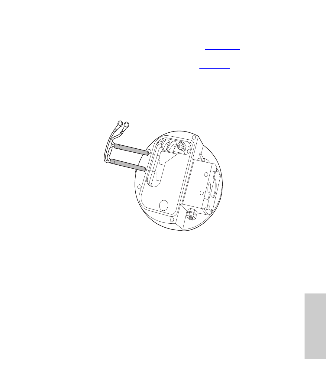
Procedure
Vent the instrument according to the procedure in Section 5.2.5
Note:
these steps.
1. Remove the cover plate (shown as a cutaway in Figure 5-15
2. Remove the two screws securing the heater cartridge ring tags from the PEEK
terminal block (Figure 5 -15
3. Care fully bend the ring tags out of the term inal block.
4. Use the needle-nose pliers to gently retract the heater cartridges from the ion block.
Ring Tags
Cartridge Heaters
).
PEEK Terminal Block
, and proceed with
) from the ion block.
Figure 5-15 Replacing the Heater Cartri dge
5. Slide the new heater cart ri dge into the ion block with the needle-nose pliers.
6. Place the two heater cartridge ring tags onto the PEEK block terminals.
7. Tighten the two terminal block screws with a 20-mm hex wrench.
8. Reinstall the ion block cover plate. Secure it with the four hex screws.
9. Reins tall the source enclosure, probe adjustor assembly, and probe.
5.3.2 Replacing the Stainless Steel Capillary
Replace the stainless steel sample capillary on the ESI probe when it permanently clogs,
becomes contaminated, or sustains damage.
Required Materials
• Flat-head screwdriver
• Needle-nose pliers
TP01757
5
Replacing Parts 93
Page 94

• 1.5-mm hex wrench
• 6-mm hex wrench
• 5/16-in. wrench
• 7/16-in. wrench
• Capillary tube (par t number 70000 0341, reference number M955088AD)
• Loupe
Procedure
1. Remove the two end-cover retaining screws on the ESI probe with the slotted
screwdriver.
2. Loosen the set screw on the LC PEEK union with the 1.5-mm hex wrench, and
remove the probe’s end-cover.
3. Unscrew the probe tip with the 6-mm wrench, and remove it.
4. Remove the LC union with the 5/16-inch and 7/16-inch wrenches.
5. Unsc rew the coupling, and w ithdraw the capillary from the probe.
6. Remove the capillary and O-ring from the coupling. Discard the capillary, PTFE
liner, and ferrule assembly.
7. Use the needle-nose pliers to remove the conductive sleev e from the inner bore of
the probe assembly fitting.
8. Slide a GVF16 ferrule onto the liner tube.
9. Press the O-ring into the groove facing the short end of the coupling.
10. Slide the coupling, short end first, onto the capillary, followed by the new PTFE liner
tube and ferrule.
11. Slide a compression screw and ferrule onto a piece of 0.007-inch PEEK tubing.
Connect it to the opposite side of the LC union.
12. Press the capillary into the union until it seats.
13. T ight en the adapto r nut on the LC union so that it is snug but not tight.
14. Gently tug the capillary to make sure it remains secure.
15. Remove the PEEK tubing from the union.
16. Slide the conductive sleev e onto the capillary, then feed the capillary through the
probe.
17. A t tach the coupling nut to the probe, and gently tighten it with the 7/16-inch wrench.
18. Replace the probe tip, then screw down until a 0.5-mm section of the capillary
protrudes from its end (Figure 5-16
ascert ain its length.
). Use the loupe, provided in the Startup Kit, to
5
Maintaining 94
Page 95
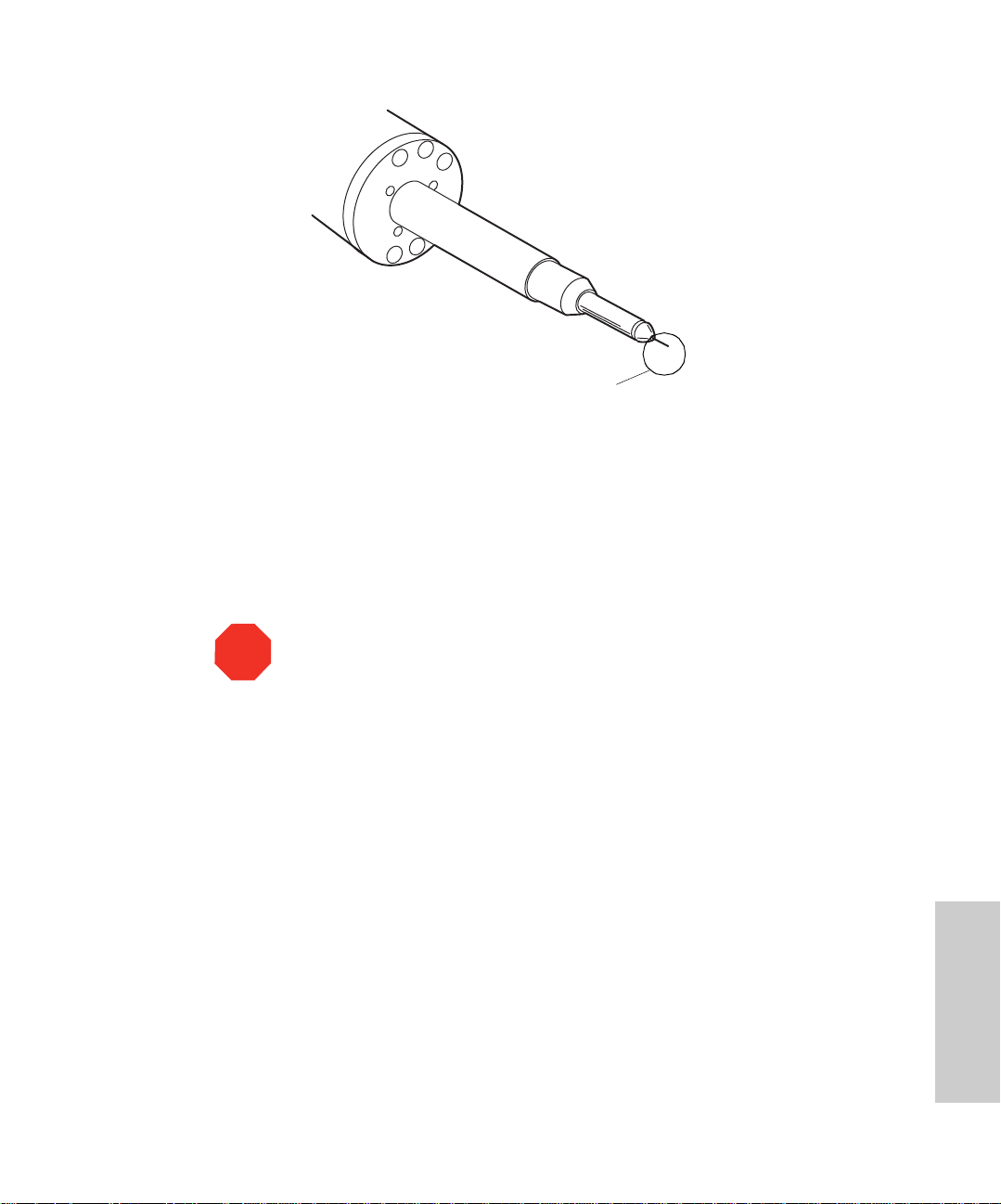
0.5-mm
Figure 5-16 ESI Probe Tip with Capillary Protrudin g 0.5 mm
19. Replace the probe end cover and secure it with the two slotted screws. Tighten the
set screw to clamp the LC union in place.
20. Before reinstalling the probe, attach it to the nebulizer gas connection and turn on
the nitrogen by selecting the API gas icon on the Tune page.
21. Make sure no nitrogen escapes from the probe tip. If you find a leak, replace the
probe tip assembly and O-ring.
Protrusion
TP01749
Attention:
Check carefully for leaks! Leakage can destroy a probe.
STOP
5.3.3 Replacing the ESI Probe Tip
Replace the probe tip if you encounter any of these problems:
• Gas leaks from the O-ring.
• A blockage in the internal metal sheathing through which the stainless steel capillary
passes.
• The threads are damaged.
Required Materials and Spare Part
• 6-mm hex wrench
• Loupe
• ESI probe tip, spare part (part number 750000337, reference number M955016BC1)
5
Replacing Parts 95
Page 96

Procedure
1. Remove the ESI probe from the source.
2. Unscrew and remove the probe tip with the 6-mm hex wrench.
3. Ins ta ll the new probe tip, and screw down until 0.5 mm of the capillary protr udes
from the end. Use the Startup Kit loupe to ascertain the capillary position.
5.3.4 Replacing the APCI Fused Silica Capillary and Filter Pad
Replace the fused silica capillary, and/or filter pad, when signal intensity decreases and
backpressure increases.
Required Materials
• 1.5-mm hex wrench
• 5/16-in. open-end wrench
• 7/16-in. open-end wrenches (2)
• Ceramic capillary cutter (part number WAT250324 in the Tools Kit)
• Butane lighter or match
• HPLC-grade methanol
• Slotted screwdriver
• Lint-free paper towels
• Loupe
Spare Parts
• Two GVF004 ferrules (part number 7000003 44, reference number 6070737)
• Fused silica (part number 430000109)
• Filter pad (part number 60 000010 3)
Procedure
1. Slide the probe tip and heater assem bly off the probe.
2. Remove the two screws from the probe’s end-cover with the slotted screwdriver.
3. Loosen the two set screws that hold the LC filter, and remove the probe end with the
hex wrench.
4. Use the two 7/16-inch wrenches to unscrew the filter from the coupling. Then
remove the ferrule from inside the filter.
5. Use the two 7/16-inch wrenches, to unscrew the two halves of the filter cartridge
and replace the filter pad. Reconnect the two filter cartridge halves.
6. Remove the old filter pad and replace it with a new one.
Maintaining 96
5
Page 97

7. Use a 7/16-inch wrenc h to unscrew the coupling from the probe. Unscrew the
adaptor nut from the probe with a 5/16-inch wrench.
8. Rem ove and discard the fused s ilic a capill ary, ferrule, and O-ring.
9. Examine the end of a length of new 300 × 100 µm fused silica capillary. Use the
loupe to ascer tain that you cut the end squarely.
Always make perpendicular cuts in the capillary , afterw ard examining them f or
Note:
squareness with the loupe.
10. Feed the fused silica capillary through the probe.
11. P ress the new O-ring into the groove facing the shor t end of the coupling.
12. S lide the coupli ng (short end first) onto the capillary and finger tighten.
13. Slide a GVF004 ferrule onto the capillary.
14. Position the filter with the flow direction arrow pointing towards the coupling.
Connect the coupling to the filter, making sure the capillary is fully seated inside the
filter.
15. T ight en only until the capillar y is snug in its fitting, then gently tug it to be sure it
remains in place.
Attention:
Overtightening the fitting can damage the capillary.
STOP
16. T ighten the coupling to the probe with a 7/16-inch wrench.
17. Run your fingers across the edges of the ceramic capillary cutter to determine which
edge is the smooth one. Use the smooth edge to cut the capillary so that 0.5 to 1
mm extends beyond the nebulizer tip.
The capillary should extend 0.5 to 1.0 mm from the end of the nebulizer. If it
Note:
does not, reinstall the capillary.
18. Uns cr ew the coupling from the probe and withdraw the capillary from it.
19. S lide a GVF 004 ferrule, followed by the adaptor nut and then another GVF004
ferrule, onto the capillary.
20. Us e a flame to remove about 20 mm of polyamide coating from the end of the
capillary. Clean with a methanol-saturated tissue.
21. Carefully reinsert the capillary into the probe. Tighten the coupling with a 7/16-inch
wrench.
22. Replace the probe end-cover and retaining screws.
23. Use the 1.5-mm hex wrench to tighten the set screws in the probe end-cover,
clamping the filter in place.
24. Replace the probe heater assembly.
5
Replacing Parts 97
Page 98

5.3.5 Replacing the APCI Probe Heater
Replace the APCI probe heater if it fails to heat.
Required Material and Spare Part
• 0.89-mm hex wrench or slotted screwdriver, depending on the type of screw that
secures the probe tip
• APCI probe heater, spare part (part number 700000337)
Procedure
1. Loosen the two set screws at the base of the probe tip assembly, and slide the probe
jacket off the assembly.
2. Separate the heater from the probe body, pulling it parallel to the axis of the probe.
3. Insta ll the new heater onto the probe end-cover.
4. Rep lace the probe tip assembly, securing it with the two set screws.
Maintaining 98
5
Page 99

Chapter 6 Troubleshooting
This chapter describes how to troubleshoot the instrument using recommended
troubleshooting procedures. This chapter addresses the following topics:
• Component hardware troubleshooting
• Checking the APCI probe
6.1 Safety and Handling
Caution:
operate the instrument. Refer to Material Safety Data Sheets f or the solv ents you use , and
know their chemical properties.
Caution:
power is applied to the instrument. Once power is turned off, wait about 10 seconds
before you disconnect an assembly.
Caution:
supply does not contain user-serviceable parts.
Observe good laboratory practice when you handle solvents, change tubing, or
To avoid possible electric shock, never disc onne ct an electrical ass em bly while
To avoid possible electric shock, do not open the power supply cover. The power
6
Attention:
STOP
chips or other components that do not require manual adjustment.
Proper Operating Procedures
To maintain optimal performance, follow the operating procedures and guidelines in this
guide.
Spare Parts
See Appendix C, Accessories and Spare Parts, for spare parts information. Parts not
included in A ppe ndix C
To prevent circuit damage from static charges, do not touch integrated circuit
are not recommended for replacement by the customer.
Safety and Handling 99
Page 100

Contacting Waters Technical Service
You can easily correct many problems. Ne v ertheless, when North American customers
cannot correct a condition, they should contact Waters Technical Service at 800
252-4752. All other customers should call their local Waters subsidiary or Waters
corporate headquarters in Milford, Massachusetts U.S.A.
When you contact Waters, be ready with this information:
• Completed normal operation checklist for the method you are using
• Nature of the sympto m
• Waters Micromass ZQ Detector model number and serial number
• Flow rate
• Operating pressure
• Mobile phase(s)
• Detector settings
• Type and serial number of column (if using an HPLC system)
• Sample description
• Control mode (MassLynx, No interaction, other)
• Software version and serial number
6
Troubleshooting 100
 Loading...