

Page 1
[ Care and Use ManUal ]
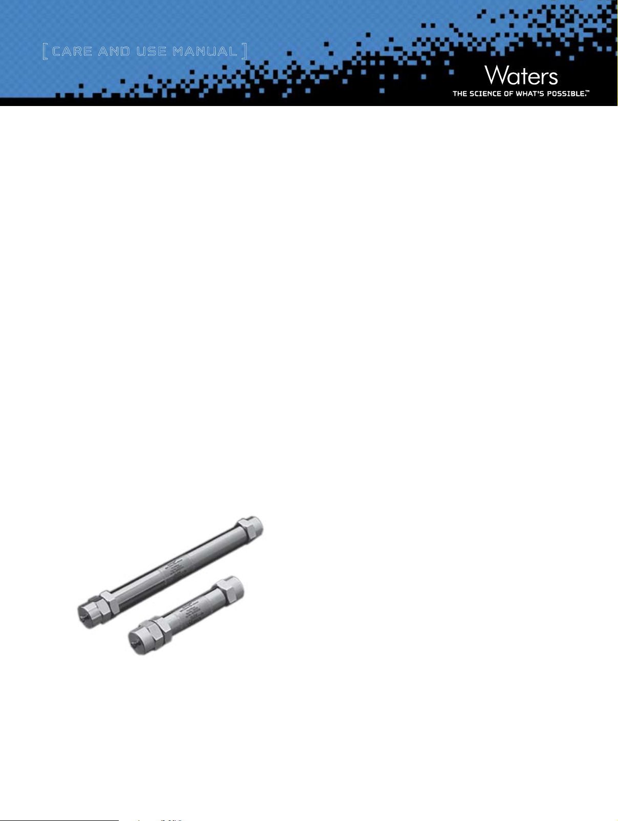
Waters envirogel gPC CleanuP Column
The Waters GPC Cleanup System uses two Envirogel™ GPC Cleanup
Columns to perform routine cleanup of environmental samples
as specified by EPA Method 3640A, GPC Cleanup. T he columns,
19 x 150 mm and 19 x 300 mm, are connected in series.
A 4.6 x 30 mm Guard Column is available for customers interested in
using a guard column in front of the column set.
The Envirogel columns:
• are packed with high-performance, fully-porous, highly
cross-linked, styrene divinylbenzene copolymer particles.
• contain 100 Å pore size material, with a nominal particle size
of 15 μm.
• are shipped with methylene chloride as the mobile phase.
• the same three columns packed in 50/50 ethyl acetate/
cyclohexane are also available.
Contents
I. Installing the Columns
a. Connecting the Column
b. Equilibrating the Columns
II. Calibrating the Columns
a. Preparing the Calibration Solution
b. Procedure
c. Injecting the Calibration Solution
d. Calculating Peak Resolution
e. Requirements
III. Column Care and Use Guidelines
IV. Column Storage
a. Short-term
b. Long-term
V. Care and Maintenance
VI. Ordering Information
Waters Envirogel GPC Cleanup Column
VII. Warrenty/Service Information
Page 2
[ Care and Use ManUal ]
i. installing tHe Columns
When installing the Waters GPC Cleanup System for the first time,
refer to Chapter 2 “Preparing the System” for instructions on
connecting the fluid lines and purging the system. This section
describes:
• Connecting columns to the system
• Equilibrating the columns
Do not connect the columns to the injector or detector until the GPC
Cleanup System is purged with methylene chloride. Refer to the
Waters GPC Cleanup System Operator’s Guide for more information.
a. Connecting Columns
To connect the columns to the system:
1. Remove the end plugs from the columns and save them for use
when storing the columns.
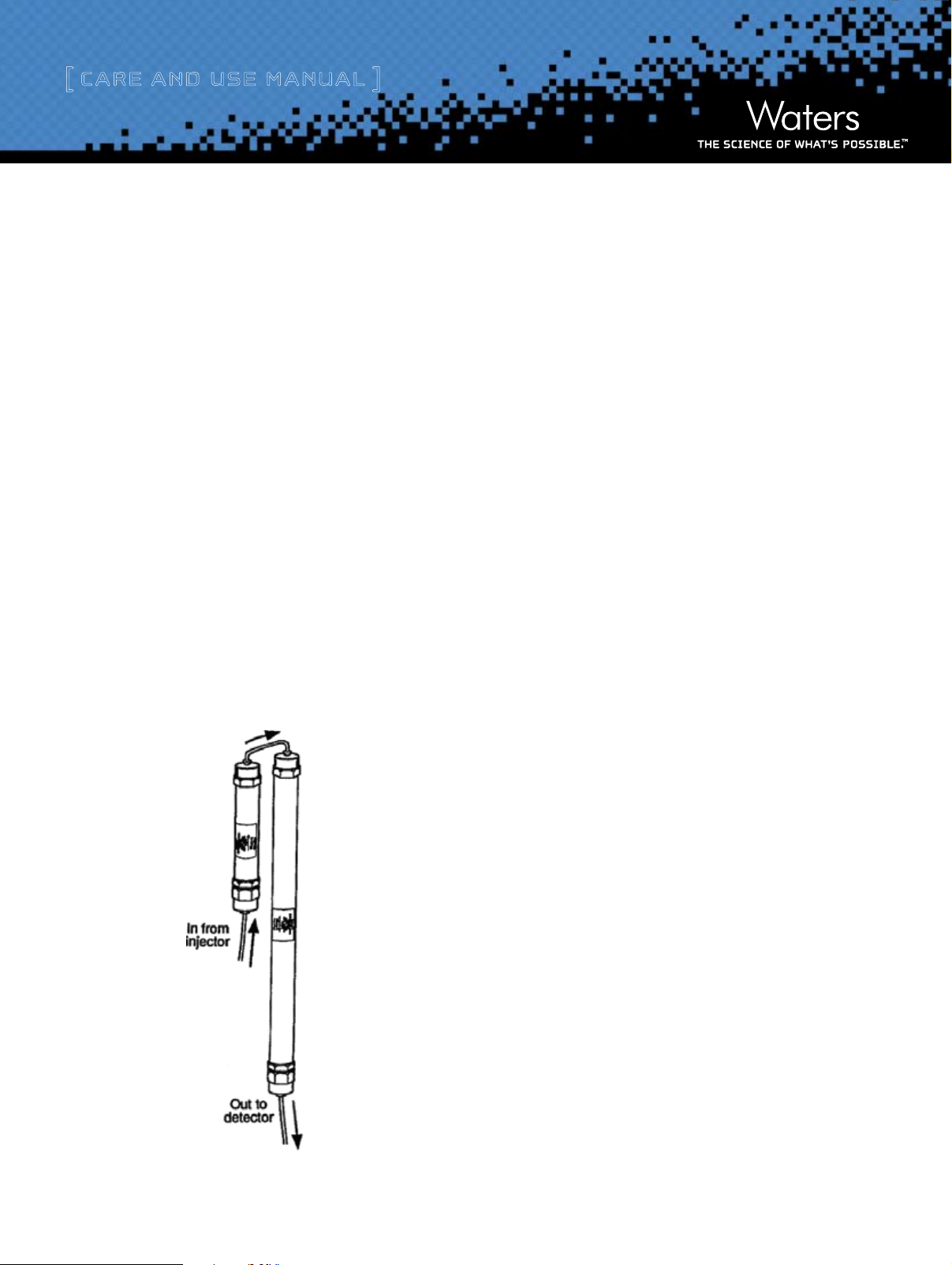
2. Place a ring stand or other column mounting device between the
injector and detector. Mount the columns so that sample flows
through the columns as shown in Figure 1.
3. Connect the tubing from the injector outlet to the column inlet
on the small column. Using a wrench, tighten the connection
1/4 to 1/2 turn beyond hand-tight. Do not over-tighten the
fittings; over-tightening damages the connection.
4. Connect the outlet of the smaller column to the inlet of the
larger column, using the 0.009-inch i.d., U-shaped, and column
joining tube.
5. Connect the column outlet tubing (supplied separately with
the detector) to the outlet of the larger column. Place a waste
collection flask at the outlet tubing from the last column.
6. Set the pump flow rate to 1 mL/min, and collect column effluent
for 1 minute.
7. Increase the flow rate 1 mL/min, and collect column effluent for
1 minute. Repeat until the flow rate is 5 mL/min.
8. Allow solvent to flow at 5 mL/min, until approximately 100 mL
of solvent is collected.
9. Set the pump flow rate to 0.0 mL/min. Allow the system pres
sureto return to 0 psi (approximately 30 seconds).
10. Connect the column outlet tubing to the sample inlet connection
on the detector.
Figure 1. Column Installation.
Waters Envirogel GPC Cleanup Column
b. Equilibrating the Columns
To equilibrate the columns:
1. Resume flow as in steps 6 and 7 above, until the flow rate is
5 mL/min.
2. Adjust the absorbance level to zero on the detector.
3. Monitor the UV absorbance on the detector to ensure that the
column is fully equilibrated. At a flow rate of 5 mL/min, full
column equilibration can take up to 20 minutes.
During this time you should observe no large fluctuations in pump
pressure (as indicated by the pump pressure transducer). Typical
pump pressures are approximately 200 psi at flow rates of 5 mL/min.
2
Page 3
[ Care and Use ManUal ]
4. Continue the flow until a stable absorbance reading is obtained.
The columns are equilibrated when the change in the absorbance
reading is ≤ 0.002 AU from zero after 500 mL of solvent passes
through the column.
5. Read just the absorbance level to zero, if necessary
ii. CaliBrating tHe Columns
The Envirogel GPC Cleanup columns are calibrated using a
calibration solution.
Calibrating the columns involves:
• Preparing the calibration solution
• Injecting the calibration solution
• Calculating peak resolution
If you are using an injector with a 5 mL sample loop, use the calibra-
tion method listed in the EPA method.
If you are using the Waters GPC Cleanup System, use the calibration
method described in this section.
Since the Waters GPC Cleanup System performs 2 mL sample injec-
tions, you must use a calibration solution that is 2.5 times more
concentrated than the calibration solution listed in the EPA method.
A 2 mL injection of the concentrated calibration solution achieves
mass loading equal to a 5 mL injection of the EPA method calibration
solution.
a. Preparing the Calibration Solution
Mix the calibration compounds into low acid methylene chloride (pesticide quality or equivalent). Refer to the Waters GPC Cleanup System
Operator’s Guide, Chapter 2 “Preparing the System” for the procedure
to determine the acid level of methylene chloride.
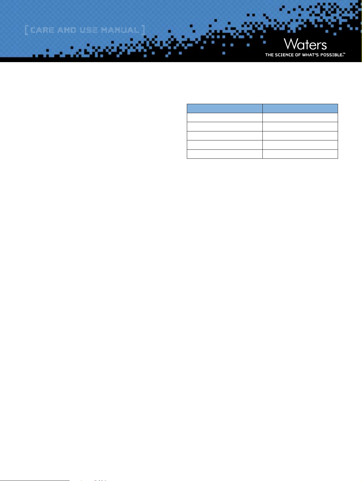
One liter of calibration solution requires the following quantities of
compounds:
Compound mg/L
Corn oil 62,500
Bis(2-ethylhexyl)phthalate 2,500
Methoxychlor 500
Perylene 50
Sulfur 200
Reduce the quantities for smaller volumes of solution.
b. Procedure
To prepare the calibration solution:
1. Weigh the Corn oil into a beaker. Since the sulfur is more soluble
in warm com oil than methylene chloride, add the sulfur to the
corn oil. Warm the mixture until the sulfur dissolves.
2. Add the remaining compounds listed in the table above to a
volumetric flask.
3. Add the warm corn oil-sulfur mixture to the volumetric flask.
4. Add methylene chloride to bring the volume of solution to one
liter.
5. Store the calibration solution away from light, at 4 ˚C, in an
®
amber bottle with a Teflon
stored up to 6 months. After storage, allow the solution to stand
at room temperature until components redissolve.
A small amount of sulfur may precipitate from the solution when the
methylene chloride is added or after the solution is stored. Remove
this precipitate by filtering the calibration solution through a GHP
®
Acrodisc
0.45 μm filter before injection.
lined screw-cap. The solution can be
Waters Envirogel GPC Cleanup Column
3
Page 4

[ Care and Use ManUal ]
c. Injecting the Calibration Solution
To inject the calibration solution:
1. Filter approximately 10 mL of calibration solution through a GHP
Acrodisc 0.45 μm filter.
2. For 717 autosamplers, fill a WISP sample vial with 3 to 4 mL
of calibration solution, and place the vial in the carriage at
position 1.
3. For manual injectors with 2 mL sample loop, fill a 10 mL syringe
with calibration solution. Inject 2 mL of solution into the sample
loop.
4. Inject the calibration solution by either:
• Pressing the RUN/STOP key on the autosampler, or
• Switching the injector to INJECT
The initial peak for corn oil appears approximately 10 to 12 minutes
after injection. The final peak for sulfur appears approximately
25 minutes after injection. Figure 2 shows a sample calibration
chromatogram.
d. Calculating Peak Resolution
To calculate the resolution between the peaks, measure the
resolution height of the valley between the peaks, and the height of
the smaller peak (Figure 3).
Figure 3. Peak Resolution.
Calculate the resolution by:
%R = 100 (1 - A/B)
Where:
R = resolution in percent
Figure 2. Sample Chromatogram
A = height of the valley
B = height of smaller peak
e. Requirements
EPA Method 3640A requires that:
• All peaks are observed and symmetrical.
• The observed resolution between the following peaks is greater
than 85%:
• Corn oil and phthalate peaks
• Phthalate and methoxychlor peaks
• Methoxychlor and perylene peaks
• The observed resolution between the perylene and sulfur peaks
is greater than 90%.
Waters Envirogel GPC Cleanup Column
4
Page 5

[ Care and Use ManUal ]
Due to variations in detector sensitivities and cell volumes, you
may need to dilute the calibration solution to achieve the specified
resolution.
Refer to the Waters GPC Cleanup System Operator’s Guide,
Chapter 3 “Calibrating the System” for information on setting frac-
tion collection times.
iii. Column Care anD use guiDelines
Gel permeation chromatography columns have a finite lifetime
directly related to their care and use. Column life is reduced
by contamination from samples and eluents, frequent solvent
changeover, and improper handling and storage.
For best results, observe the following guidelines:
• Protect the column from vibration and mechanical shock.
• Do not exceed flow rates of 9 mL/min or pressures greater than
1000 psi.
iv. Column storage
Refer to the Waters GPC Cleanup System Operator’s Guide for
system shutdown and storage procedures.
a. Short-term
During short-term column storage (storage overnight or a weekend),
ensure that columns do not dry out. Leave the system power ON, and
reduce the flow rate to the column to 0.5 mL/min. Divert the detector
output to waste. Recalibrate the system upon startup.
b. Long-term
Follow the long-term shutdown procedure in the Waters GPC
Cleanup System Operator’s Guide. Return the column to its box with
the end plugs firmly in place. Store the column at room temperature.
• Do not use mobile phases which include water, ketones, alkanes,
or alcohols (except hexafluoroisopropanol).
• Protect the column from rapid changes in pressure, which can
result from rapidly changing the flow rate of the solvent. Change
flow rates in increments no more than 11 mL/min each minute.
• Dedicate columns to a specific application. Frequently switching
samples and solvents accelerates column deterioration and loss
of resolution.
• Be sure that columns do not dry out. Replace the end plugs when
storing the columns.
Waters Envirogel GPC Cleanup Column
5
Page 6

[ Care and Use ManUal ]
v. Care anD maintenanCe
General care and maintenance procedures are addressed in the Waters GPC Cleanup System Operator’s Guide. Additional symptoms that you
may observe are listed in Table 1. Recalibrate columns after any cleaning procedure.
Table 1. Troubleshooting
Problem Possible Cause Corrective Action
High pressure shutdown Clogged fluid path Change all filters in fluid path. Filter all samples and
solvents before use. Replace all tubing.
Flush column at 2 m by reversing direction of flow through
column.
Replace column.
Low operating pressure Leaks Tighten all fluid connections.
Insufficient solvent Refill solvent reservoir.
Air in-line Purge system.
Retention times too long Pump flow rate set too low Check flow setting and verify output.
Leaks Tighten fluid connections.
Wrong columns Verify length and diameter.
Retention times too short Pump flow rate set too fast Check flow rate setting and verify output.
Data collection device improperly connected Ensure data collection starts at inject signal.
Wrong columns Verify length and diameter.
No peaks, poor recovery Solvent flow too low Verify pump pressure.
Injector blocked or leaking Check for leaks or blockage.
Detector malfunctioning Check wavelength, sensitivity, signal output cables.
Broad, smeared peaks, or peaks
appear as doublet
Rearrangement of packed bed or void in the
column packing
Blockage or leak in injector sample loop Check for leaks or excessive pressure drop across sample
Check system performance with each column separately.
Reverse flow through affected column using 2 mL injections
of toluene or xylene at 2 mL/min. If not corrected after 10
injections, replace column.
loop. Back flush loop.
In-line or inlet filter is partially clogged Reverse flow through column and inject 2 mL of
tetrahydrofuran, butylchloride, or a mixture of 1:1
cyclohexane:methylene chloride. Change the inlet filters.
Retention times shift more than 5%Change in flow rate Check flow rate.
Change in laboratory temperature Stabilize laboratory temperature or column temperature.
Waters Envirogel GPC Cleanup Column
6
Page 7

[ Care and Use ManUal ]
Sales Offices:
Austria and European Export
(Central South Eastern Europe,
CIS and Middle East) 431 877 18 07
Australia 2 9933 1777
Belgium 32 2 726 1000
Brazil 55 11 5094 3788
Canada 800 252 4752
China 8621 6495 6999
CIS/Russia +7 495 3367000
Czech Republic 42 02 617 11384
Denmark 45 46 59 8080
Finland +358 9 5659 6288
France (33) 1 30 48 72 00
Germany 49 6196 400600
Hong Kong 852 29 64 1800
Hungary 36 1 350 5086
India and India Subcontinent
91 80 2 837 1900
Ireland 353 1 448 1500
Italy 39 02 274 211
Japan (81) 3 3471 7191
Korea (82) 2 820 2700
Mexico 5255 5200 1860
The Netherlands +31 (0)76-50 87 200
Norway 47 63 84 60 50
Poland (48) 22 833 4400
Puerto Rico 787 747 8445
Singapore 65 6273 1221
Spain 34 93 600 93 00
Sweden 46 8 555 11500
Switzerland 41 62 889 2030
Taiwan 886 2 2543 1898
Waters Envirogel GPC Cleanup Column
United Kingdom 44 208 238 6100
©2007 Waters Corporation. Waters, The Science of W hat’s Possible
and Envirogel are trademarks of Waters Corporation. Acrodisc is a registered trademark of Pall Corporation. Teflon is a registered trademark
of the E.I. du Pont do Nemours Company. All rights reserved.
October 2007 WAT036556 Rev 4 VW-PDF
Waters Corporation
34 Maple Street
Milford, MA 01757 U.S.A.
T: 1 508 478 2000
F: 1 508 872 1990
www.waters.com
 Loading...