

Page 1
[ Care and Use ManUal ]
AtLAntIs t3, dc18 And HILIc sILIcA coLuMns
I. IntroductIon
Thank you for choosing an Atlantis® Column. The manufacture of Atlantis
columns begins with ultrapure reagents to control the chemical composition
and p urity of the final product. Atlantis columns are manufactured in a cGMP,
ISO 9001:2000 certified plant with each step being conducted within nar-
row tolerances. Every column is individually tested and Certificates of Batch
Analysis and a Performance Chromatogram are provided with each column.
™
Waters recommends the use of Sentry
lifetime and protect the column from contaminants.
guard columns to maximize column
contents
I. IntroductIon
II. connectInG tHe coLuMn or cArtrIdGe to tHe
III. systeM ModIfIcAtIon recoMMendAtIons
HPLc systeM
IV. WAters sMALL PArtIcLe sIze (3 µM) coLuMns
– fAst cHroMAtoGrAPHy
V. coLuMn equILIbrAtIon
VI. coLuMn InstALLAtIon Procedure
VII. coLuMn PerforMAnce VALIdAtIon
VIII. InItIAL coLuMn effIcIency deterMInAtIon
IX. coLuMn usAGe
XII. HILIc GettInG stArted
Atlantis Columns
XIII. coLuMn cLeAnInG, reGenerAtInG And storAGe
XIV. troubLesHootInG
1
Page 2

[ Care and Use ManUal ]
II. CONNECTING THE COLUMN OR CARTRIDGE TO THE HPLC
SYSTEM
a. Column Connection
Handle the column with care. Do not drop or hit the column on a hard
surface as this may disturb the bed and affect its performance.
1. Correct connection of 1/16 inch outer diameter stainless steel
tubing leading to and from the column is essential for high-qual-
ity chromatographic results.
2. An arrow on the column identification label indicates correct
direction of solvent flow.
3. When using standard stainless steel compression screw fittings,
it is important to ensure proper fit of the 1/16 inch outer diameter
stai nless s teel t ubing. W hen t igh teni ng or l oose ning the c omp res -
sion screw, place a 5/16 inch wrench on the compression screw
and a 3/8 inch wrench on the hex head of the column endfitting.
Caution: If one of the wrenches is placed on the column flat during this
process, the endfitting will be loosened and leak. Under-tightening
compression screws or using worn ferrules can lead to solvent
leaking. Care should be taken to check all column connections
for leaks to avoid exposure to solvents and the hazards associ-
ated with such exposure including risks to health and electrical
connections.
4. If a leak occurs between the stainless steel compression screw fit-
ting and the column endfitting, a new compression screw fitting,
tubing and ferrule must be assembled.
b. Cartridge Connection
Handle the cartridge with care. Do not drop or hit the cartridge on a
hard surface as it may disturb the bed and affect its performance. Refer
to Figure 1 for an exploded view of an Atlantis cartridge column with
a Sentry guard column.
1. Unscrew end connectors from the old cartridge. Leave them con-
nected to the inlet and outlet lines of the instrument.
2. Attach new cartridge column between connectors so that the
direction of the flow arrow on the label is pointing in the direc-
tion of mobile phase flow (toward detector).
3. Fingertighten all fittings.
Caution: Under-tightening the connectors can lead to solvent leak-
ing. Care should be taken to check all column connections for leaks
to avoid exposure to solvents and the hazards associated with such
exposure including risks to health and electrical connections.
4. Check for leaks once flow has been initiated. If a leak occurs
between the connector and the column endfitting, the column
may be misaligned in the connector or the Kalrez O-ring must be
replaced in the connector.
It is important to realize that extra column peak broadening can destroy
a successful separation. T he choice of appropriate column connectors
and system tubing is discussed in detail below.
c. Column Connectors and System Tubing Considerations
Due to the absence of an industry standard, various column man
facturers have employed different types of chromatographic column
connectors. The chromatographic performance of the separation can
be negatively affected if the style of the column endfittings does
not match the existing tubing ferrule setting. This section explains
the differences between Waters style and Parker style ferrules and
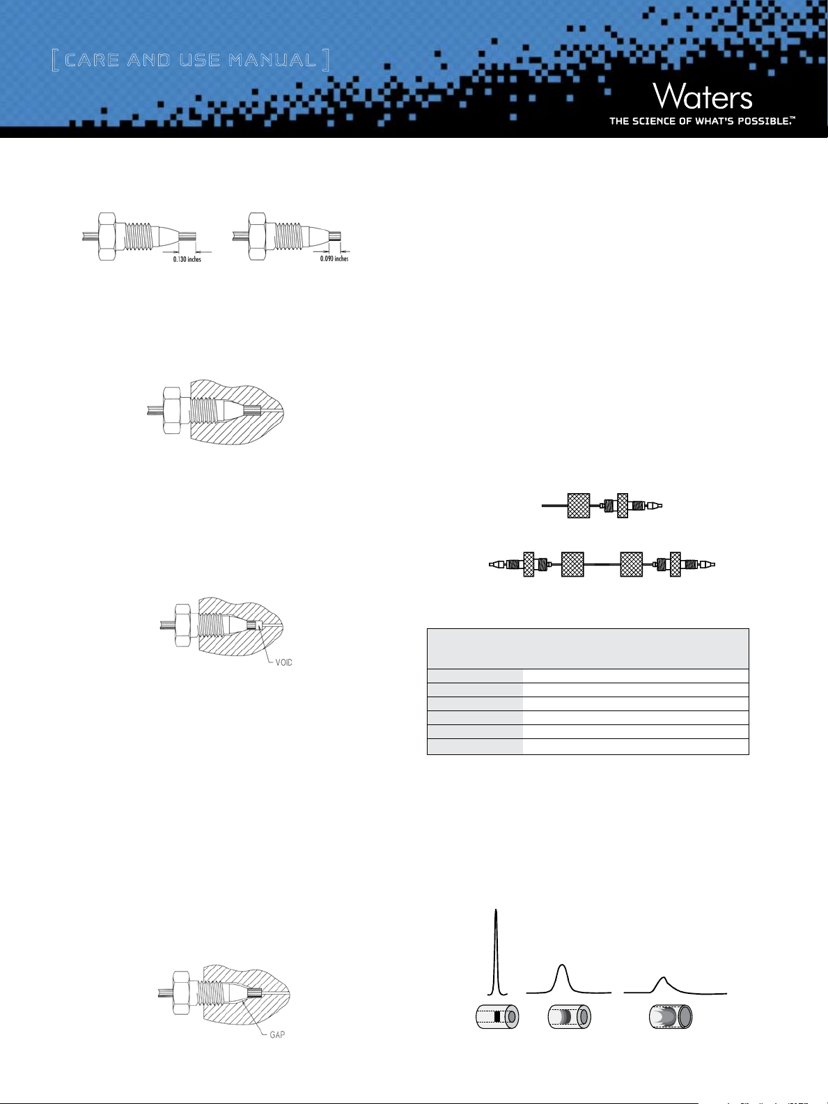
endfittings (Figure 2). Each endfitting style varies in the required
length of the tubing protruding from the ferrule. The Atlantis column
is equipped with Waters style endfittings, which require a 0.130 inch
ferrule. If a non-Waters style column is presently being used, it is
critical that ferrule depth be reset for optimal performance prior to
installing an Atlantis column. In a proper tubing/column connection
(Figure 3), the tubing touches the bottom of the column endfitting,
with no void between them.
Figure 1: Installation of Atlantis Cartridge Column with Sentry Guard Column
Spacer
Sentry™ Guard
0.25 mm (0.009 inch) Tubing Atlantis® Cartridge Column
Atlantis Columns
Column
C-Clip
2
End Connector
Page 3
[ Care and Use ManUal ]
Diluted/Distorted Sample Band
0.005 inches
0.020 inches
0.040 inches
Figure 2: Waters and Parker Ferrule Types
Waters Ferrule Setting Parker Ferrule Setting
Figure 3: Proper Tubing/Column Connection
Tubing touches the bottom of the column endfitting, with no void between them.
Attention: A void will occur if tubing with a Parker ferrule is connected
to a Waters style endfitting (Figure 4). This will dramatically reduce the
efficiency of the column and cause peak shape distortion.
Figure 4: Parker Ferrule in a Waters Style Endfitting
There are two ways to fix the problem:
1. Tighten the screw a bit more. The ferrule moves forward, and
reaches the sealing surface. Do not overtighten since this may
break the screw.
2. Cut the tubing, replace the ferrule and make a new connection.
Alternatively, replace the conventional compression screw fitting with
™
an all-in-on e PE EK
fitting (Waters Part Number PSL613315) that allows
resetting of the ferrule depth. Another approach is to use a Thermo
™
Hypersil
Keystone, Inc. SLIPFREE® connector to ensure the correct
fit. The fingertight SLIPFREE connectors automatically adjust to fit all
compression screw type fittings without the use of tools (Figure 6).
Figure 6: Single and Double SLIPFREE Connectors
To fix this problem: Cut the end of the tubing with the ferrule, place a
new ferrule on the tubing and make a new connection. Before tighten-
ing the screw, make sure that the tubing bottoms out in the endfitting
of the column.
Conversely, if tubing with a Waters ferrule is connected to a column
with Parker style endfitting, the end of the tubing will bottom out
before the ferrule reaches its proper sealing position. This will leave a
gap and create a leak (Figure 5).
Caution: The connection will leak if a Waters ferrule is connected to a
column with a Parker style endfitting.
Figure 5: Waters Ferrule in a Parker Style Endfitting
Table 1. Waters Part Numbers for SLIPFREE Connectors
SLIPFREE Type and Tubing Internal Diameter
Tubing Length 0.005” 0.010” 0.020”
Single 6 cm PSL 618000 PSL 618006 PSL 618012
Single 10 cm PSL 618002 PSL 618008 PSL 618014
Single 20 cm PSL 618004 PSL 618010 PSL 618016
Double 6 cm PSL 618001 PSL 618007 PSL 618013
Double 10 cm PSL 618003 PSL 618009 PSL 618015
Double 20 cm PSL 618005 PSL 618001 PSL 618017
d. Band Spreading Minimization
Internal tubing diameter influences system band spreading and peak
shape. Larger tubing diameters cause excessive peak broadening and
lower sensitivity (Figure 7).
Figure 7: Effect of Connecting Tubing on System
Atlantis Columns
3
Page 4

[ Care and Use ManUal ]
Ti me
Inflection
point time
1.0
0.8
0.6
0.4
Au
0.2
0.0
e. Measuring System Bandspread Volume
This test should be performed on an HPLC system with a single wave-
length UV detector (not a Photodiode Array (PDA)).
1. Disconnect column from system and replace with a zero dead
volume union.
2. Set flow rate to 1 mL/min.
3. Dilute a test mix in mobile phase to give a detector sensitiv-
ity 0.5-1.0 AUFS (system start up test mix can be used which
contains uracil, ethyl and propyl parabens; Waters Part Number
WAT034544).
4. Inject 2 to 5 µL of this solution.
5. Using 5 sigma method measure the peak width at 4.4% of peak
height:
Band Spreading (µL) = Peak Width (min) x Flow Rate (µL/min)
= 0.1 min x 1000 µL/min
= 100 µL
3. Equilibrate the system with eluent A until a stable baseline is
achieved.
4. Switch to 100% eluent B.
5. Record the half height of the step and determine dwell volume
(Figure 9).
Figure 9: Determination of Dwell Volume
The dwell volume should be less than 1 mL. If the dwell volume is
greater than 1 mL, see
how to reduce system volume.
System Modification Recommendations“ for
“
Figure 8: Determination of System Bandspread
Volume Using 5-Sigma Method
In a typical HPLC system, the Bandspread Volume should be 100 µL ±
30 µL.
In a microbore (for 2.1 mm i.d. columns) system, the Bandspread
Volume should be no greater than 20 to 40 µL.
f. Measuring Gradient Delay Volume
1. Replace the column with a zero dead volume union.
2. Prepare eluent A (pure solvent, such as methanol) and eluent
Atlantis Columns
B (solvent plus sample, such as 5.6 mg/mL propylparaben in
methanol).
g. Use of Smaller i.d. Columns
A 3.0 mm i.d. narrow-bore column usually requires no system modifi-
cations. A 2.1 mm i.d. microbore column, however, requires modifica-
tions to the HPLC system to eliminate excessive system bandspread
volume. Without proper system modifications, excessive system
bandspread volume causes peak broadening and has a large impact on
peak width as peak volume decreases.
h. Impact of Bandspread Volume on 2.1 mm i.d. Column
Performance
System with 70 µL bandspread: 10,000 plates
System with 130 µL bandspread: 8,000 plates (same column)
Attention: Flow splitters after the column will introduce additional band
spreading which will reduce sensitivity and resolution. Loss of sensitiv-
ity or resolution may affect the accuracy and/or precision of results.
System optimization, especially in a system that contains a flow splitter,
can have dramatic effects on sensitivity and resolution. Optimization
includes using correct-depth ferrules and minimizing tubing diameter
and lengths. System optimization results in a doubling of sensitivity and
resolution of the metabolite in an LC/MS/MS system (Figure 10).
4
Page 5

[ Care and Use ManUal ]
7.00 7.50
Non-optimized LC/MS/MS System Optimized System
8.00
7.00 7.50 8.00
Figure 10: Chromatograms Obtained Using Non-Optimized vs.
Optimized LC/MS/MS System
III. systeM ModIfIcAtIon recoMMendAtIons
1. Use a microbore detector flowcell with ≤ 2.1 mm i.d. columns.
Attention: Detector sensitivity is reduced with the shorter flowcell
pathlength in order to achieve lower bandspread volume.
2. Minimize injector sample loop volume.
3. Use 0.009 inch (0.25 mm) i.d. tubing between pump and
injector.
4. Use 0.009 inch (0.25 mm) i.d. tubing for rest of connections with
> 3.0 mm i.d. columns. Use 0.005 inch (0.12 mm) i.d. tubing for
narrow-bore (≤ 2.1 mm i.d.) systems.
5. Use perfect (pre-cut) connections (with a variable depth inlet if
using columns from different suppliers).
6. Detector time constants should be shortened to less than 0.2 seconds
and the sampling rate adjusted to obtain at least 20 data points
across peaks of interest.
IV. WAters sMALL PArtIcLe sIze (3 µM) coLuMns
– fAst cHroMAtoGrAPHy
Waters columns with 3 µm particles provide faster and more efficient
separations without sacrificing column lifetime. This section describes
five parameters to consider when performing separations with columns
containing 3 µm particles.
Note: Columns that contain 3 µm particles have smaller pore-size outlet
frits to retain packing material than are used at the inlet. These columns
should not be backflushed.
1. Flow Rate — Compared to columns with 5 µm particles, columns
with 3 µm particles have higher optimum flow rates and are used
when high efficiency and short analysis times are required. These
higher flow rates, however, lead to increased backpressure.
Note: Use a flow rate that is practical for your system.
2. Backpressure — Backpressures for columns with 3 µm particles
are higher than for 5 µm columns with the same dimensions.
Waters suggests using a shorter column to compensate for
increased back pressure and to obtain a shorter analysis time.
3. Temperature — Use a higher temperature to reduce backpressure
caused by smaller particle sizes. The recommended temperature
range for Atlantis columns is 20 °C to 45 °C. See “Column Usage”
for a discussion of elevated temperature use with Atlantis columns.
4. Sampling Rate — Use a sampling rate of about 10 points per
second.
5. Detector Time Constant — Use a time constant of 0.1 seconds for
fast analyses.
V. coLuMn equILIbrAtIon
Atlantis columns are packed and shipped in 100% acetonitrile. It is
important to ensure solvent compatibility before changing to a new
solvent.
Atlantis T3 and dC
- Equilibrate with a minimum of 10 column vol-
18
umes of the mobile phase to be used (refer to Table 2 for a listing of
standard column volumes).
At l an ti s H I L IC Si li c a – Upon receipt, equilibrate with 50 column volumes
of 50:50 acetonitrile:water with 10 mM final buffer concentration (refer
to Table 2 for a listing of standard column volumes). Prior to the first
injection, equilibrate with 20 column volumes of initial mobile phase
conditions. See “HILIC Getting Started” for additional information.
Table 2. Standard Column Volumes in mL (Multiply by 10 for
Equilibration Mobile Phase Volumes)
Column Volume (mL)
Column Column internal diameter (mm)
Length 1.0 2.1 3.0 3.9 4.6 7.8 10 19 30 50
15 mm – 0.1 – – – – – – – –
20 mm – 0.1 0.1 – 0.3 – – – – –
30 mm – 0.1 0.2 – 0.5 – 2.4 8 – –
50 mm 0.1 0.2 0.3 – 0.8 2.4 4 14 35 98
100 mm 0.1 0.4 0.7 1.2 1.7 5 8 28 70 –
150 mm 0.1 0.5 1.0 1.8 2.5 7 12 42 106 294
250 mm – 0.9 1.8 – 4 – 20 70 176 490
300 mm – – – – – 14 24 85 212 589
Atlantis Columns
5
Page 6

[ Care and Use ManUal ]
VI. coLuMn InstALLAtIon Procedure
Note: The flow rates given in the procedure below are for a typical 4.6
mm i.d. column. Scale the flow rate up or down
the column i.d., length, particle size and backpressure of the Atlantis column
being installed. See “Scaling Up/Down” for calculating flow rates when changing
column i.d. and/or length.
1. Purge the pumping system and connect the inlet end of the column
to the injector outlet.
2. Set the pump flow to 0.1 mL/min and increase to 1 mL/min over
5 minutes.
3. When the mobile phase is flowing freely from the column out-
let, stop the flow, then attach the column to the detector. This
prevents entry of air into the detector and provides more rapid
baseline equilibration.
Caution: Care should be taken to check column connections for
leaks to avoid exposure to solvents and the hazards associ-
ated with such exposure including risks to health and electrical
connections.
accordingly based upon
T3 and Atlantis dC
The Performance Test Chromatogram is specific to each individual
column and contains information such as batc h number, column serial
number, USP plate count, USP tailing factor, capacity factor and chro-
matographic results and conditions. T hese data should be stored for
future reference.
), and chromatographic results and conditions.
18
VIII. InItIAL coLuMn effIcIency deterMInAtIon
1. Perform an efficiency test on the column before using it. Waters rec-
ommends using a suitable solute mixture, as found in the “Perfor-
mance Test Chromatogram”, to verify the performance of the column
upon receipt.
2. Determine the number of theoretical plates (N) and use for peri-
odic comparison.
3. Repeat the test periodically to track column performance over
time. Slight variations may be obtained on two different HPLC
systems due to the quality of the connections, operating environ-
ment, system electronics, reagent quality, column condition and
operator technique.
4. When the mobile phase is changed, gradually increase the flow
rate of the new mobile phase from 0.0 mL/min to 1.0 mL/min in
0.1 mL/min increments.
5. Once a steady backpressure and baseline have been achieved, the
column is ready to be used (or equilibrated).
Note: If mobile phase additives are present in low concentrations
(e.g., ion-pairing reagents), 100 to 200 column volumes may be
required for complete equilibration. In addition, mobile phases
that contain formate (e.g., ammonium formate, formic acid, etc.)
may also require slightly longer initial column equilibration times.
Please see additional equilibration information for Atlantis HILIC
Silica columns in “HILIC Getting Started.”
VII. coLuMn PerforMAnce VALIdAtIon
Each Atlantis column comes with a Certificate of Batch Analysis and
a Performance Test Chromatogram. The Certificate of Analysis is spe-
cific to each batch of packing material and includes the batch number,
analysis of unbonded particles, analysis of bonded particles (Atlantis
Note: If 1) is performed, the isocratic efficiencies measured in your
laboratory may be less than those given on the Waters “Perfor-
mance Test Chromatogram.” This is normal. The Waters isocratic
column testing systems have been modified in order to achieve
extremely low system volumes. This presents a more challeng-
ing test of how well the column was packed. This guarantees the
highest quality packed column. These special testing systems have
been modified to such an extent that they are not commercially
viable and have limited method flexibility other than isocratic
column testing.
IX. coLuMn usAGe
Caution: Accumulation of particulates from solvents, samples, or pump
seals may cause the column backpressure to increase over time. This
may lead to a system shutdown or leaking of column connections.
Accumulation of contaminants from “dirty” samples at the column
inlet may lead to a loss of resolution or ion suppression in a mass
spectrometer, resulting in erroneous results.
Atlantis Columns
6
Page 7

[ Care and Use ManUal ]
To ensure the continued high performance of Atlantis columns and
cartridges, follow these guidelines:
a. Guard Columns
Use a Waters Sentry guard cartridge of matching i.d., chemistry and
particle size between the injector and main column. For best results, the
guard column should be replaced prior to the observation of a substantial
loss in resolution or increase in system backpressure. It is important to use
a high-performance matching guard column to protect the main column
while not compromising or changing analytical resolution.
b. Sample Preparation
1. Sample impurities often contribute to column contamination. Use
®
Waters Oasis
of the appropriate chemistry to cleanup the sample before analysis.
2. For reversed-phase separations (Atlantis T3 and dC
sample in mobile phase or a solvent that is weaker (less organic
modifier) than the mobile phase. For Hydrophilic Interaction
Chromatography (HILIC) separations (Atlantis
samples must be prepared in 100% organic solvents (e.g., aceto-
nitrile). See “HILIC Getting Started” for additional information.
3. If the sample is not dissolved in the mobile phase, ensure that the
sample and diluent are miscible in the mobile phase(s) in order to
avoid sample and/or diluent precipitation.
4. Filter sample through a 0.2 µm membrane to remove particulates.
If the sample is dissolved in a solvent that contains an organic
modifier (e.g., acetonitrile, methanol, etc.) ensure that the
membrane material does not dissolve in the solvent. Contact the
membrane manufacturer with solvent compatibility questions.
c. Recommended pH Range
Atlantis HILIC Silica: 1-5 Atlantis T3: 2-8 Atlantis dC
Column lifetime will vary depending upon the temperature, type and
concentration of buffer used. A listing of recommended and non-rec-
ommended buffers is given in Table 3. Please use this as a guideline
when developing methods.
or Sep-Pak® solid-phase extraction cartridges/columns
) prepare the
18
HILIC Silica), the
: 3-7
18:
Attention: Operating at the upper or lower end of the pH range in com-
bination with elevated temperatures will lead to shorter column lifetime
and/or may result in the column generating high backpressure.
Table 3: Buffer recommendations for using Atlantis columns
from pH 1 to 7
Additive or Buffer range Used for
Buffer pKa (±1 pH unit) Volatility Mass Spec? Comments
TFA 0.3 Volatile Yes Ion pair additive, can suppress MS signal.
Used in the 0.01-0.1% range.
Formic Acid 3.75 Volatile Yes Maximum buffering obtained when used with
Ammonium Formate salt. Used in 0.1-1.0% range.
Acetic Acid 4.76 Volatile Yes Maximum buffering obtained when used with
Ammonium Acetate salt. Used in 0.1-1.0% range.
Formate 3.75 2.75 – 4.75 Volatile Yes Used in the 1-10mM range. Note: sodium or
COOH) potassium salts are not volatile.
(NH
4
Acetate 4.76 3.76 – 5.76 Volatile Yes Used in the 1-10mM range. Note: sodium or
COOH) potassium salts are not volatile.
(NH
4CH2
Phosphate 1* 2.15 1.15 – 3.15 Non-volatile No Traditional low pH buffer, good UV transparency
Phosphate 2* 7.2 6.20 – 8.20 Non-volatile No Much shorter colum lifetimes will be realized
using phosphate at pH 7
* Phosphate salt buffers are not recommended for HILIC (phosphoric acid is OK) due to phosphate buffer
salt insolubility at high acetonitrile concentrations.
d. Solvents
To maintain maximum column performance, use high quality chrom-
atography grade solvents. Filter all aqueous buffers prior to use. The
addition of at least 5% organic to neutral pH buffers is recommended
®
to prevent bacterial growth. Pall Corporation Acrodisc
filters are
recommended. Solvents containing suspended particulate materials
will generally clog the outside surface of the inlet frit of the column.
This will result in higher operating pressure and poorer performance.
Degas all solvents thoroughly before use to prevent bubble formation
in the pump and detector. The use of an on-line degassing unit is also
recommended. This is especially important when running low pressure
gradients since bubble formation can occur as a result of aqueous and
organic solvent mixing during the gradient.
e. Pressure
Atlantis columns can tolerate pressures of up to 6,000 psi (400 bar
or 40 Mpa) although pressures greater than 4,000 - 5,000 psi should
be avoided in order to maximize column and system lifetimes, and the
risk of system shutdowns and leaking.
Atlantis Columns
7
Page 8

[ Care and Use ManUal ]
f. Temperature
Temperatures between 20 ˚C - 45 ˚C are recommended for operating
Atlantis columns in order to enhance selectivity, lower solvent viscosity
and increase mass transfer rates. However, any temperature rise above
ambient will have a negative effect on lifetime which will vary depend-
ing on the pH and buffer conditions used. The combination of operating
at elevated temperatures and at pH extremes should be avoided.
g. Scaling Up/Down Isocratic Methods
The following formulas will allow scale up or scale down, while main-
taining the same linear velocity (retention time), and provide new
sample loading values:
If column i.d. and length are altered: F2 = F1(r2/r1)
or: Load2 = Load1(r2/r1)2(L2/L1)
or: Inj vol
Where: r = Radius of the column, in mm
F = Flow rate, in mL/min
L = Length of column, in mm
1 = Original, or reference column
2 = New column
2
= Inj vol2 (r2/r1)2 (L2/L1)
1
XII. HILIc GettInG stArted
a. Equilibration of Atlantis HILIC Silica Columns
1. Upon receipt, equilibrate in 50% acetonitrile/50% aqueous buffer
(10 mM final buffer concentration) for 50 column volumes.
2. Prior to first injection, equilibrate with 20 column volumes of
initial mobile phase conditions.
3. When running gradients, equilibrate with 10 column volumes
between injections.
Failure to appropriately equilibrate the column could result in drifting
retention times.
2. Maintain at least 40% organic solvent (e.g., acetonitrile) in your
mobile phase or gradient.
3. Avoid phosphate salt buffers to avoid precipitation in HILIC mobile
phases (phosphoric acid is OK).
4. Buffers such as ammonium formate or ammonium acetate, will
produce more reproducible results than additives such as formic
acid or acetic acid. If an additive (e.g., formic acid) must be used
instead of a buffer, use 0.2% (v:v) instead of 0.1%.
5. For best peak shape, maintain a buffer concentration of 10 mM in
your mobile phase/gradient at all times.
c. Injection Solvents for HILIC
1. If possible, injection solvents should be 100% organic solvent.
Water must be eliminated or minimized. Choose weak HILIC
solvents such as acetonitrile, isopropanol, methanol, etc.
2. A generic injection solvent is 75:25 acetonitrile methanol. This is
a good compromise between analyte solubility and peak shape.
3. Avoid water and dimethylsulfoxide (DMSO) as injection solvents.
These solvents will produce very poor peak shapes.
4. Exchange water or DMSO with acetonitrile by using reversed-
phase solid-phase extraction. If this is not possible, dilute the
water or DMSO with organic solvent.
d. Additional HILIC Recommendations
1. For initial scouting conditions, run a gradient from 95% acetoni-
trile to 50% acetonitrile. If no retention occurs, run isocratically
with 95:3:2 acetonitrile:methanol:aqueous buffer.
2. Alternate polar solvents such as methanol, acetone or isopro-
panol can also be used in place of water in the mobile phase to
increase retention.
b. HILIC Mobile Phase Considerations
1. Always maintain at least 5% polar solvent in the mobile phase
or gradient (e.g., 5% water, 5% methanol or 3% methanol/2%
aqueous buffer, etc.). T his ensures that the Atlantis HILIC Silica
particle is always hydrated.
Atlantis Columns
3. Be sure that your needle wash solvent/purge solvent contains the
same high organic solvent concentration as your mobile phase,
else peak shapes will suffer.
8
Page 9

[ Care and Use ManUal ]
XIII. coLuMn cLeAnInG, reGenerAtInG And storAGe
a. Cleaning and Regeneration
A sudden increase in pressure or shift in retention or resolution may
indicate contamination of the column.
Atlantis T3 and dC
the non-polar contaminant(s). If this flushing procedure does not solve
the problem, purge the column with a sequence of progressively more
non-polar solvents. For example, switch from water to tetrahydrofuran
to methylene chloride. Return to the standard mobile phase conditions
by reversing the sequence.
Atlantis HILIC Silica – Flush with 50:50 acetonitrile:water to remove
the polar contaminant(s). If this flushing procedure does not solve the
problem, purge the column with 5:95 acetonitrile:water.
Guard columns require replacement at regular intervals as determined
by sample contamination. When system backpressure increases above
a set pressure limit, it is usually an indication that the guard column
should be replaced. A sudden appearance of split peaks is also indica-
tive of a need to replace the guard column.
– Flush with a neat organic solvent to remove
18
b. Storage
Atlantis T3 and dC18 – For period s longer than four days, store the c olumn
in 100% acetonitrile. Do not store columns in buffered eluents. If the
mobile phase contained a buffer salt, flush the column with 10 column
volumes of HPLC grade water (see Table 2 for common column volumes)
and replace with 100% acetonitrile for storage. Failure to perform this
intermediate step could result in precipitation of the buffer salt in the
column when 100% acetonitrile is introduced.
Atlantis HILIC Silic a – For periods longer than four days, store the column
in 95:5 acetonitrile:water. Do not store in buffered eluents. If the mobile
phase contained a buffer salt, flush the column with 10 column volumes of
95:5 acetonitrile:water (refer to Table 2 for a listing of standard column
volumes) prior to storage.
Completely seal column to avoid evaporation and drying out of the bed.
Note: If a column has been run with a formate-containing mobile phase
(e.g., ammonium formate, formic acid, etc.) and is flushed to remove the
buffer, slightly longer equilibration times may be required after the column
is re-installed and run again with a formate-containing mobile phase.
XIV. Troubleshooting
Changes in retention time, resolution, or backpressure are often due to
column contamination (refer to “Column Cleaning, Regenerating and
Storage”). Information on column troubleshooting problems may be
found in HPLC Columns Theory, Technology and Practice, U.D. Neue,
(Wiley-VCH, 1997) or the Waters HPLC Troubleshooting Guide (Litera-
ture Code 720000181EN).
Atlantis Columns
9
Page 10

[ Care and Use ManUal ]
Sales Offices:
Austria and European Export
(Central South Eastern Europe,
CIS and Middle East) 431 877 18 07
Australia 2 9933 1777
Belgium 32 2 726 1000
Brazil 55 11 5094 3788
Canada 800 252 4752
China 8621 6495 6999
CIS/Russia +7 495 3367000
Czech Republic 42 02 617 11384
Denmark 45 46 59 8080
Finland +358 9 5659 6288
France (33) 1 30 48 72 00
Germany 49 6196 400600
Hong Kong 852 29 64 1800
Hungary 36 1 350 5086
India and India Subcontinent
91 80 2 837 1900
Ireland 353 1 448 1500
Italy 39 02 274 211
Japan (81) 3 3471 7191
Korea (82) 2 820 2700
Mexico 5255 5200 1860
The Netherlands +31 (0)76-50 87 200
Norway 47 63 84 60 50
Poland (48) 22 833 4400
Puerto Rico 787 747 8445
Singapore 65 6273 1221
Spain 34 93 600 93 00
Sweden 46 8 555 11500
Switzerland 41 62 889 2030
Taiwan 886 2 2543 1898
Atlantis Columns
United Kingdom 44 208 238 6100
©2007 Waters Corporation. Waters, The Science of W hat’s
Possible, Atlantis, Sentry, Oasis, and SepPak are trademarks of
Waters Corporation. All ot her trademarks are acknowledged.
November 2007 736000640 Rev H IH-PDF
10
Waters Corporation
34 Maple Street
Milford, MA 01757 U.S.A.
T: 1 508 478 2000
F: 1 508 872 1990
www.waters.com
 Loading...