

Page 1
[ CARE AND USE MANUAL ]
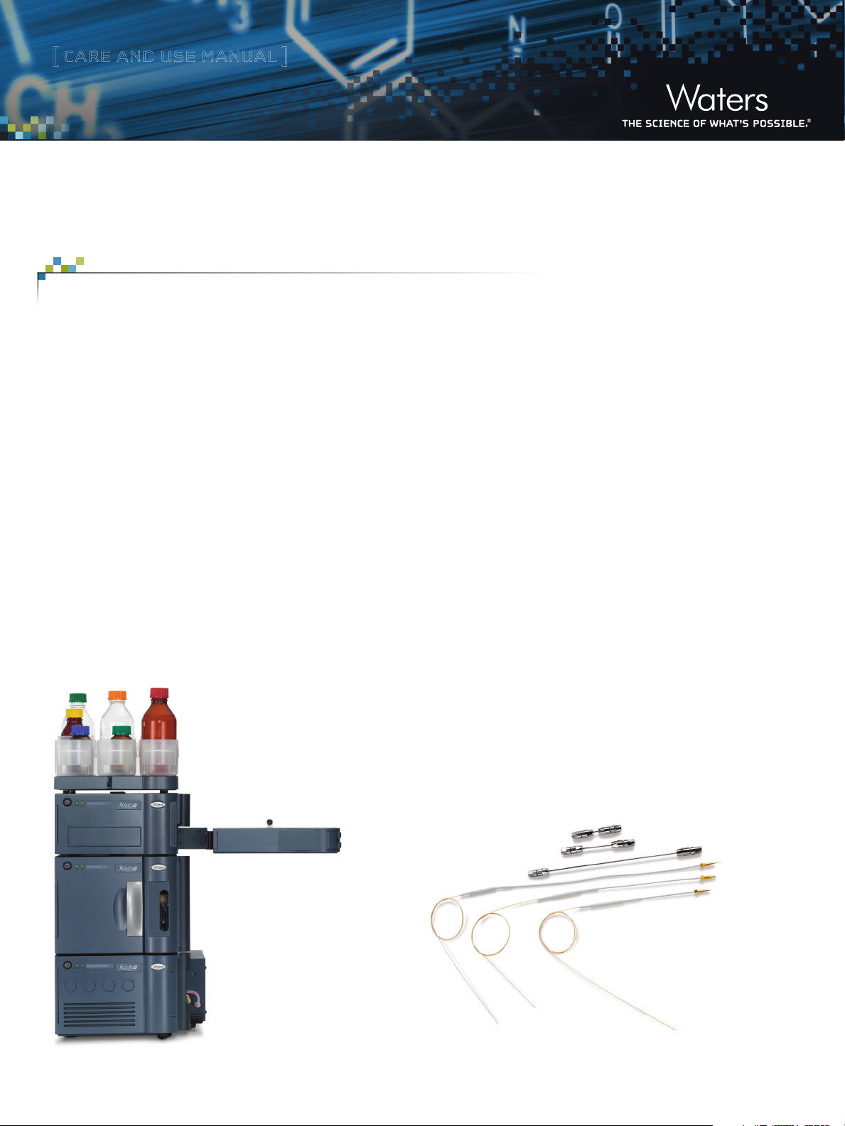
ACQUITY UPLC M-Class Columns
TABLE OF CONTENTS
I. PREPARING ELUENTS
II. SAMPLE PREPARATION
III. PREPARING AND CONNECTING 75, 100, AND
150 µM I.D. ACQUITY UPLC M-CLASS COLUMNS
IV. PREPARING AND CONNECTING 300 µM I.D.
ACQUITY UPLC M-CLASS COLUMNS
V. CARE WHEN STOPPING FLOW
VI. HOW TO DIAGNOSE AND ADDRESS ABNORMALLY
HIGH BACKPRESSURE AND LEAKS
VII. CHECKING AND CLEANING A FOULED EMITTER
VIII. LONG TERM COLUMN STORAGE
IX. ORDERING INFORMATION
Note: Gloves should be worn for ALL operations
detailed in this document.
INTRODUCTION
Waters® ACQUITY UPLC® M-Class Columns are manufactured
to exacting specifications and are designed for use at pressures
up to 15000 psi. In order to achieve maximum performance, it is
important to ensure that proper connections are made to minimize
peak tailing and poor efficiency.
Each ACQUITY UPLC M-Class Column is individually tested to
ensure that it passes stringent quality control. Compared to
standard flow chromatography, successful day-to-day performance
of capillary-flow systems can require extra attention to detail.
This document provides several essential recommendations for
the successful use of ACQUITY UPLC M-Class Columns.
ACQUITY UPLC M-Class System.
ACQUITY UPLC M-Class Columns are available in 75, 100, 150, and 300 μm I.D.s.
Page 2
[ CARE AND USE MANUAL ]
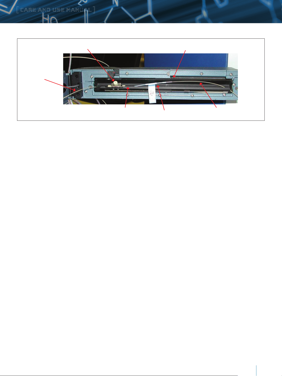
Nano-Tee with magnetic mount
Tubing to
HTM valve
outlet tubing
I. PREPARING ELUENTS
Do not filter organic solvents. Use MS grade solvents directly
from the bottle.
A solvent: 100% water with 0.1% formic acid.
B solvent: 100% acetonitrile or methanol with 0.1% formic acid.
Seal wash solvent: water, may contain small amount of
organic (no acid).
Inner compartment (swiveled open)
Analytical column
Tubing to MS sourceTrapping column
II. SAMPLE PREPARATION
Samples for expression analysis must contain tryptic peptides
derived from proteins of interest at suitable concentrations.
Samples may contain buffers and residual reagents from
approved digestion procedure.
The sample must not contain other reagents, denaturants,
detergents, lipids, and must be free of particulates.
Weak needle wash for peptides: 3% acetonitrile with 0.1%
formic acid.
Note:
Good lab practices: no solvent bottles to go through the
dishwasher!
Wear gloves when handling solvent lines and hardware.
If system is contaminated with poor quality solvents,
flush with appropriate solvent.
Many report successful use of solution containing 25% water,
25% acetonitrile, 25% methanol, 25% IPA and 0.1% formic acid.
For PEG contamination, flush system with IPA.
DO NOT USE strong bases, as they can strip fused silica.
Where to source solvents:
In North America: Fisher Optima or Burdick & Jackson.
In Europe: Biosolve (Netherlands) provide very good solvents.
They offer smaller bottles (0.5 L) as well as “UPLC”
grade solvents.
III. PREPARING AND CONNECTING 75, 100 OR
150 µM I.D. ACQUIT Y UPLC M-CLASS COLUMNS
a) Preparation
Carefully remove your column from bag.
The gold ferrule on the inlet of the column is placed snugly on the
tubing at the factory. The ferrule is lightly secured to reduce the
risk of it being lost as the column is removed from the packaging.
The ferrule is purposely set high on the tubing but will properly
seat itself in the correct position upon tightening.
A small piece of Teflon® tubing is present on the outlet end of the
column for those who want to connect the device to a UV or PDA
detector rather than a mass spectrometer.
Note: The column is attached to a transfer tube with the use of a
zero dead volume union. This is hidden beneath the heat shrink
tubing. Care must be taken NOT to apply excessive force on the
ends of the nano column (e.g., when removing teflon tubing at
column outlet) that could cause this joint to separate.
ACQUITY UPLC M-Class Column Care & Use
2
Page 3
[ CARE AND USE MANUAL ]
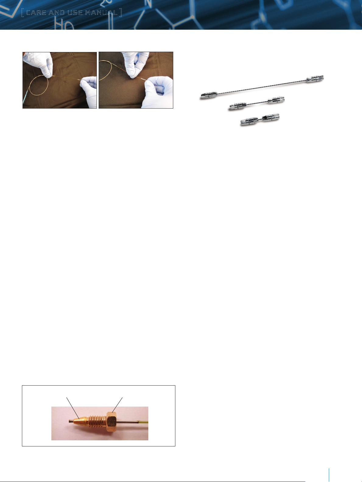
Wrong Correct
Carefully grab the teflon tubing with one hand and the BARE FUSED
SILICA capillary, not the PEEK tubing, with the other hand, to remove
the Teflon sleeve. Again, be careful NOT to apply unnecessary force
when removing the teflon tubing which could cause the fragile joint
between transfer tube and packed capillary to separate.
b) Connection
Connecting and proper tightening of 75, 100, or 150 µm I.D.,
ACQUITY UPLC M-Class Columns to 15 K ACQUITY UPLC system.
Flow mobile phase only in the direction indicated by the arrow
on the column label. Connect the column with the direction of
the flow arrow on the label pointing to the detector or Mass
Spectrometer.
1. For a column never installed on an ACQUITY UPLC
M-Class System.
Turn nut until hand tight then an additional 1/2 turn
IV. PREPARING AND CONNECTING
300 µM I.D. ACQUITY UPLC M-CLASS COLUMNS
Carefully remove column from box.
Connect the column inlet to the injector utilizing a Valco style
compression screw.
Connect the column outlet to the detector or Mass Spectrometer
using a Valco style compression screw.
V. CARE WHEN STOPPING FLOW
Do not stop the flow to your ACQUITY UPLC M-Class Column
suddenly. It is critical that the flow be slowly lowered via
the ACQUITY UPLC M-Class System controller to prevent
column damage.
2. For a previously installed and removed column from
ACQUITY UPLC M-Class System.
Hand tight plus 1/8 turn
“Hand Tight” is when the ferrule bottoms in the M-detail fitting.
The ferrule is pre-staked higher than necessary on the tube, so
the ferrule must be seated by hand (hand tight) or lightly with
a wrench, then an additional turn. Note: In virtually every case,
gentle wrenching is required to get to the “hand tight” state
before the final half turn. Taking “hand tight” or “finger tight” too
literally can result in under tightening/leaks.
Note: DO NOT over tighten, leaking may occur and/or the ferrule
may become stuck in the port.
Ferrule Nut
VI. HOW TO DIAGNOSE AND ADDRESS
ABNORMALLY HIGH BACKPRESSURE AND LEAKS
The inlet or the head of a chromatography column experiences
the largest amount of pressure in a LC system. The
ACQUITY UPLC M-Class Column inlet is designed to
operate at pressures up to 15 K psi.
The fluidic pressure drops across the column at the outlet of the
column should only experience atmospheric pressure. The outlet
connection which connects the column to the transfer capillary is
designed to handle a maximum pressure of 800 psi.
With a higher than normal system pressure, a small leak might be
detected at the outlet of an ACQUITY UPLC M-Class Column.
ACQUITY UPLC M-Class Column Care & Use
3
Page 4

[ CARE AND USE MANUAL ]
Problem
If a clog or a blockage is created after the ACQUIT Y UPLC
M-Class Column (e.g., at emitter) the pressure at the outlet
of the column may rise.
The increase in pressure at the column outlet may create a
temporary leak between the column and the transfer tubing.
The most common source of post column clogs is a blocked
nanospray emitter.
Note: Set high pressure limit on the ACQUITY UPLC M-Class
System to approximatively 1000 psi above maximum normal
operating pressure.
Diagnosis 1
The pressure traces in the console window show an increase in
pressure during the analytical gradient (red arrows) between two
injections (highlighted by the red squares).
Diagnosis 2
This shows the increase in system pressure must originate after the
trap column.
Notice the pressure during the trapping portions of the analysis did
not increase between injections (red arrows).
Representative diagram of ACQUITY UPLC M-Class System with attached trap and
ACQUITY UPLC M-Class Column.
ACQUITY UPLC M-Class Column Care & Use
4
Page 5

[ CARE AND USE MANUAL ]
Diagnosis 3
A clogged emitter may still produce an ion signal.
The charged emitter may act as an APCI needle and ionize the gas
in the source producing ions for the mass spectrometer (below).
Test for a clogged emitter
If the system pressure drops more than 200 psi the emitter
is clogged.
Remove the column transfer tubing from the universal sprayer
(or other nanospray source).
Note: In normal use, stop the flow and wait for the pressure to drop
to zero before breaking the connection at the union to minimize
the chance of dislodging potential particulates in the union and
having them be swept into (and clog) the emitter. If one needs to
disconnect to relieve pressure, it is much better to disconnect the
outlet end, as shown here, rather than the inlet.
The sprayer should be retracted to shut off the high voltage before
touching the sprayer.
Should your ACQUITY UPLC M-Class Column be replaced?
Excessive pressure at the column outlet may create a small leak.
If the column outlet only experiences excess pressure for a short
period of time the column should still be acceptable for use since
the union between packed column and transfer tube can “recover.”
If the column outlet experiences pressure over an extended period
of time (e.g., overnight) the union between the column and the
transfer tubing may be permanently compromised. Any nonreversible open space created between the column and transfer
line may lead to band broadening (wider peaks).
VII. CHECKING AND CLEANING A FOULED EMITTER
Examine the emitter
Examining a clogged nanospray emitter under a microscope may
allow the user to determine the source of the clog.
Fused silica particles: These particles will be transparent and have
sharp, fractured edges. Fused silica particles can be created when
a column and an emitter are joined with too much force (over
tightened union).
Organic material: The material will appear brown in color (bottom).
Organic material can derive from a dirty sample or solvents.
GLOVES MUST BE WORN to prevent contamination with
undesired biological material.
Clean emitter
Emitter clogged with organic residue
Examining the Union (Part Number 700002843, available on waters.com).
ACQUITY UPLC M-Class Column Care & Use
5
Page 6

[ CARE AND USE MANUAL ]
1. Remove the clogged emitter and the column from the union on
the universal sprayer.
2. Remove the PEEK nuts on either end.
3. Loosen the screw on the sliding portion of the sprayer and
remove the union.
5. Even if the union does not appear to be clogged it should be
cleaned to remove any small particulates.
Cleaning the Union (Method #1)
As the union is 100% stainless steel, 20% nitric acid in water
can be used to clean it. This aggressive procedure helps ensure
that the union becomes free of even the strongest contaminations.
In addition, it provides excellent electric contact for
electrospray ionization.
Wash the outside of the outlet capillary and fitting with
water/acetronitrile (50/50) before reconnecting to union.
Note: Again for demonstration purposes only, these photos show
fittings and tubing being handled with bare fingers, which is
known to introduce contamination in the system. It is therefore
critical that customers ALWAYS wear clean, powder-free gloves
when changing tubing or handling fittings.
4. Hold the union up to a light (above). Light should shine through
an unclogged union. If the union is completely clogged the
obstruction must be removed.
Note: Do not mix nitric acid with organic acids, as they will react
and produce high volumes of CO2.
To order the Union: Waters PN 700002843
To order Peek Fitting: Waters PN 700002842
Cleaning the Union (Method #2)
The union can be cleaned by sonication in a solution of IPA/water
for at least 15 minutes.
After sonication, remove any residual solvent by flushing the
union with air or nitrogen.
After cleaning, examine the union with a microscope and ensure
that any particulate matter has been removed. While looking at
the union be sure the internal threads and opening have not been
scored or damaged in any way.
If the obstruction within the union cannot be removed or it
appears damaged please replace the union.
Note: In many cases it is best to simply REPLACE the union
whenever a new emitter is used.
ACQUITY UPLC M-Class Column Care & Use
6
Page 7

[ CARE AND USE MANUAL ]
Replace the Emitter
Place the pin plug at the back side of the union. This will mark the
center of the union (right).
Thread the replacement emitter (back end first) through the front
of the sprayer and into the union.
Tighten the PEEK nut around the union carefully (do not
over-tighten).
Remove the pin plug and replace it with the transfer line from the
ACQUITY UPLC M-Class Column (again, do not over-tighten
the fitting).
To reduce the occurrence of clogging
Make sure the union between the column and emitter is clean.
Do not over tighten the fittings on the union (finger tight only).
Make sure the UPLC solvents are clean.
Keep a flow on the tip even when the instrument is not in use
(as low as 200 nL/min).
Try using a TaperTip instead of a Pulled Tip Emitter if
clogging persists.
TaperTip Emitter
A TaperTip (P/N 186003932) is offered as an alternative to a
PicoTip and is the default emitter in the universal sprayer kit.
(July, 2007). The TaperTip has an I.D. of 20 µm but unlike the
PicoTip the I.D. remains unchanged throughout the emitter. This
allows the emitter to be implemented for higher flow rates.
Furthermore, the TaperTip may experience a lower frequency
of particle clogging.
About poorly cut fittings
DO NOT cut or modify the emitter or column tubing.
All tubing and columns supplied by Waters are pre-cut and polished.
Improperly cut tubing can lead to "shedding" and introduction of
fused silica particles downstream of ACQUITY M-Class 75, 100,
or 150 µm I.D. Columns. This consequently can cause undesired
system backpressure increases.
Note: Compared to the PicoTip Emitter, Waters TaperTip Emitter does
not produce as stable a spray at 250-400 nL/min, which is the flow
rate range most customers use with 75 μm or 100 μm I.D. columns.
As indicated above, use of the TaperTip Emitter is the suggested
when a more robust device is preferred.
Column I.D. Optimal Flow Rate (nL/min) Emitter Type
75 µm 300 PicoTip
100 µm 400-500 PicoTip/TaperTip
150 µm 1000 TaperTip
300 µm 4000 ESI Source required
ACQUITY UPLC M-Class Column Care & Use
7
Page 8

[ CARE AND USE MANUAL ]
What flow rate can I use with each type of emitter?
The flow rate of an LC method should be determined by the
optimal flow rate for the particular column. The optimal flow rate
is directly related to the column I.D.
A PicoTip is ideally suited for nanospray applications while the
TaperTip is suited for microspray applications (>1 µL/min).
Waters currently does not recommend the use of a nanospray
source for the 300 µm column format.
VIII. LONG TERM ACQUITY UPLC M-CLASS
COLUMN STORAGE
When not in use, it is recommended to maintain flow through
the ACQUITY UPLC M-Class Column using 100% eluent B to
maximize bed stability and minimize potential bed drying.
If prolonged column storage is required or if the column needs
to be removed from the system, it is recommended that the
ACQUITY UPLC M-Class Column be flushed with 100% organic
solvent containing no TFA or FA (e.g., simply store in
100% acetonitrile).
IX. ORDERING INFORMATION
ACQUITY UPLC M-Class Columns
Product Description Particle Size Dimensions Part Number
ACQUITY UPLC M-Class BEH C18, 130Å 5 µm 300 µm x 50 mm 186007471
ACQUITY UPLC M-Class HSS T3 1.8 µm 300 µm x 150 mm 186007472
ACQUITY UPLC M-Class HSS T3 1.8 µm 75 µm x 150 mm 186007473
ACQUITY UPLC M-Class HSS T3 1.8 µm 75 µm x 250 mm 186007474
ACQUITY UPLC M-Class CSH C
ACQUITY UPLC M-Class CSH C
ACQUITY UPLC M-Class CSH C18, 130Å 1.7 µm 75 µm x 200 mm 18 60 0747 7
ACQUITY UPLC M-Class CSH C18, 130Å 1.7 µm 75 µm x 250 mm 18 60 0747 8
ACQUITY UPLC M-Class CSH C18, 130Å 1.7 µm 100 µm x 100 mm 186007479
ACQUITY UPLC M-Class CSH C18, 130Å 1.7 µm 150 µm x 100 mm 186007480
ACQUITY UPLC M-Class CSH C
ACQUITY UPLC M-Class CSH C18, 130Å 1.7 µm 150 µm x 150 mm 186 007514
ACQUITY UPLC M-Class BEH C
ACQUITY UPLC M-Class BEH C18, 130Å 1.7 µ m 75 µm x 150 mm 186007482
ACQUITY UPLC M-Class BEH C18, 130Å 1.7 µ m 75 µm x 200 mm 186007483
ACQUITY UPLC M-Class BEH C18, 130Å 1.7 µ m 75 µm x 250 mm 186007484
ACQUITY UPLC M-Class BEH C18, 130Å 1.7 µ m 100 µm x 100 mm 18 60 07485
ACQUITY UPLC M-Class BEH C18, 130Å 1.7 µ m 150 µm x 100 mm 186007486
ACQUITY UPLC M-Class BEH C18, 300Å 1.7 µ m 75 µm x 100 mm 186007487
ACQUITY UPLC M-Class BEH C18, 300Å 1.7 µ m 100 µm x 100 mm 18 60 07488
ACQUITY UPLC M-Class BEH C18, 300Å 1.7 µ m 150 µm x 100 mm 186007489
ACQUITY UPLC M-Class BEH C18, 300Å 1.7 µ m 75 µm x 150 mm 18600749 0
ACQUITY UPLC M-Class BEH C18, 300Å 1.7 µ m 75 µm x 200 mm 186 007491
ACQUITY UPLC M-Class BEH C18, 300Å 1.7 µ m 75 µm x 250 mm 18600749 2
ACQUITY UPLC M-Class BEH C4, 300Å 1.7 µm 75 µm x 100 mm 1860074 93
ACQUITY UPLC M-Class BEH C4, 300Å 1.7 µm 100 µm x 100 mm 18 60 0749 4
ACQUITY UPLC M-Class BEH C4, 300Å 1.7 µm 150 µm x 100 mm 18 60 0749 5
ACQUITY UPLC M-Class Symmetry C18 Trap, 10 0Å 5 µm 180 µm x 20 mm 18600749 6
ACQUITY UPLC M-Class Symmetry C18 2D Trap, 100Å 5 µm 180 µm x 20 mm 18 6007497
ACQUITY UPLC M-Class Symmetry C18 Trap, 10 0Å 5 µm 300 µm x 50 mm 18600749 8
ACQUITY UPLC M-Class Symmetry C18 2D HCP Trap, 100Å 5 µm 300 µm x 25 mm 18600749 9
ACQUITY UPLC M-Class Symmetry C18 V/V Trap, 100Å 5 µm 180 µm x 20 mm 186007500
, 130Å 1.7 µm 75 µm x 100 mm 18 60 07475
18
, 130Å 1.7 µm 75 µm x 150 mm 18 60 07476
18
, 130Å 1.7 µm 150 µm x 50 mm 186007513
18
, 130Å 1.7 µ m 75 µm x 100 mm 186007481
18
1
2
1
2
1
1
Trap columns designed for 1D (low pH only) work. These 1D traps are reversible.
2
Trap columns designed for 2D (high pH/low pH) work. These 2D traps are not reversible.
ACQUITY UPLC M-Class Column Care & Use
8
Page 9

[ CARE AND USE MANUAL ]
SALES OFFICES
Austria 43 1 877 18 07
Australia 61 2 9933 1777
Belgium and Luxembourg 32 2 726 1000
Brazil 55 11 4134 3788
Canada 1 800 252 4752
China 86 21 6156 2666
Czech Republic 420 2 617 11384
Denmark 45 46 59 8080
Finland 358 9 5659 6288
France 33 1 30 48 72 00
Germany 49 6196 400 600
Hong Kong 852 2964 1800
Hungary 36 1 350 5086
India 080 49292200 03
Japan 81 3 3471 7191
Korea 82 2 6300 4800
Mexico 52 55 52 00 1860
The Netherlands 31 76 508 7200
Norway 47 6 384 6050
Poland 48 22 101 5900
Portugal 351 21 893 61 77
Puerto Rico 1 787 747 8445
Russia/CIS 7 495 727 4490 / 290 9737
Singapore 65 6593 7100
Spain 34 93 600 9300
Sweden 46 8 555 115 00
Switzerland 41 56 676 7000
Taiwan 886 2 2501 9928
Ireland 353 1 448 1500
Israel 9723 3731391
Italy 39 02 265 0983
UK 44 208 238 6100
US 1 800 252 4752
Waters, The Science of W hat’s Possible, ACQUITY UPLC, UPLC, and Symmetry are registered trademarks of Waters Corporation. CSH is a
trademark of Waters Corporation. All other trademarks are the property of their respective owners.
©2014 Waters Corporation. Produced in the U.S.A.
March 2014 720004944EN Rev A LM-PDF
Waters Corporation
34 Maple Street
Milford, MA 01757 U.S.A.
T: 1 508 478 2000
F: 1 508 872 1990
www.waters.com
 Loading...