

Page 1

Waters 432 Conductivity
t
Detector
Operator’s Guide
34 Maple Stree
Milford, MA 01757
71500043202, Revision A
Page 2

NOTICE
The information in this document is subject to change without notice and should not be
construed as a commitment by Waters Corporation. Waters Corporation assumes no
responsibility for any errors that may appear in this document. This document is believed
to be complete and a c cu rate at th e time o f p u blication. In no event shall Water s
Corporation be liable for incidental or consequential damages in connection with or arising
from the use of this document.
1994–2003 WATERS CORPORATION. PRINTED IN THE UNITED STATES OF
AMERICA. ALL RIGHTS RESERVED. THIS DOCUMEBNT OR PARTS THEREOF MAY
NOT BE REPRODUCED IN ANY FORM WITHOUT THE WRITTEN PERMISSION OF
THE PUBLISHER.
Alliance, Millennium, and Waters are registered trademarks, and Empower, LAC/E,
PowerLine, SAT/IN, Sep-Pak, UltraWISP, and WISP are trademarks of Waters
Corporation.
All other trademarks or registered trademarks are the sole property of their respective
owners.
Page 3

When you use the instrument, follow generally accepted procedures for quality
P
Note:
control and methods development.
If you observe a change in the retention of a particular compound, in the resolution
between two compounds, or in peak shape, immediately determine the reason for the
changes. Until you determine the cause of a change, do not rely on the separation results.
The Installation Category (Overvoltage Category) for this instrument is Level II. The
Note:
Level II Category pertains to equipment that receives its electrical power from a local level,
such as an electrical wall outlet.
STO
Atención:
responsible for compliance could void the user’s authority to operate the equipment.
Importan t :
par l’autorité responsable de la conformité à la réglementation peut annuler le droit de
l’utilisateur à exploiter l’équipement.
Achtun g :
ausdrückliche Genehmigung der für die ordnungsgemäße Fun ktion stüchtigkeit
verantwortlichen Personen kann zum Entzug der Bedienungsbefugnis des Systems
führen.
Avvertenza:
espressamente approvate da un ente responsabile per la conformità annulleranno
l’autorità dell’utente ad operare l’apparecchiatura.
Atención:
expresamente aprobado por la parte responsable del cumplimiento puede anular la
autorización del usuario para utilizar el equip o .
Changes or modifications to this unit not expressly approved by the party
Toute modification sur cette unité n’ayant pas été expressément approuvée
Jedwede Änderungen oder Modifikationen an dem Gerät ohne die
eventuali modifiche o alterazioni apportate a questa unità e non
cualquier cambio o modificación efectuado en esta unidad que no haya sido
Page 4

Caution:
Use caution when working with any polymer tubing under pressure:
• Always wear ey e protection when near pressurized polymer tubing.
• Extinguish all nearby flames.
• Do not use Tefzel tubing that has been severely stressed or kinked.
• Do not use Tefzel tubing with tetrahydrofuran (THF) or concentrated nitric or
sulfuric ac id s.
• Be aware that methylene chlor ide and dimethyl sulfoxide cause Tefzel tubing to
swell, which greatly reduces the rupture pressure of the tubing.
Attention :
Soyez très prudent en travaillant avec des tuyaux de polymères sous
pression :
• Portez toujours des lunettes de protection quand vous vous trouvez à proximité de
tuyaux de polymères.
• Eteignez toutes les flammes se trouvant à proximité.
• N'utilisez pas de tuyau de Tefzel fortement abîmé ou déformé.
• N'utilisez pas de tuyau de Tefzel avec de l'acide sulfurique ou nitrique, ou du
tétrahydrofurane (THF).
• Sachez que le chlorure de méthylène et le sulfoxyde de diméthyle peuvent
provoquer le gonflement des tuyaux de Tefzel, diminuant ainsi for tem ent leur
pression de rupture.
Vorsicht:
Bei der Arbeit mit Polymerschläuchen unter Druck ist besondere Vorsicht
angebracht:
• In der Nähe von unter Druck stehenden Polymerschläuchen stets Schutzbrille
tragen.
• Alle offenen Flammen in der Nähe löschen.
• Keine Tefzel-Schläuche verwenden, die stark geknickt oder überbeansprucht sind.
• Tefzel-Schläuche nicht für Tetrahydrofuran (THF) oder konzentrierte Salpeter- oder
Schwefelsäure verwenden.
• Durch Methylenchlorid und Dimethylsulfoxid können Tefzel-Schläuche quel len;
dadurch wird der Berstdruck des Schlauches erheblich reduziert.
Page 5

Precauzio ne :
prestare attenzione durante le operazioni con i tubi di polimero sotto
pressione:
• Indossare sempre occhiali da lavoro protettivi nei pressi di tubi di polimero
pressurizzati.
• Estinguere ogni fonte di ignizione circostante.
• Non utilizzare tubi Tefzel soggetti a sollecitazioni eccessive o incurvati.
• Non utilizzare tubi Tefzel contenenti tetraidrofurano (THF) o acido solforico o nitrico
concentrato.
• Tenere presente che il cloruro di metilene e il dimetilsolfossido provocano
rigonfiamento nei tubi Tefzel, che riducono not evolmente il limite di pressione di
rottura dei tubi stessi.
Advertencia:
manipular con precaución los tubos de polímero bajo presión:
• Protegerse siempre los ojos en las proximidades de tubos de polímero bajo
presión.
• Apagar todas las llamas que estén a proximidad.
• No utilizar tubos Tefzel que hayan sufrido tensiones extremas o hayan sido
doblados.
• No utilizar tubos Tefzel con tetrahidrofurano (THF) o ácidos nítrico o sulfúrico
concentrados.
• No olvidar que el cloruro de metileno y el óxido de azufre dimetilo dilatan los tubos
Tefzel, lo que reduce en gran medida la presión de ruptura de los tubos.
Page 6

Page 7

Caution:
The user shall be made aware that if the equipment is used in a manner not
specified by the manufacturer, the protection provided by the equipment may be impaired.
Attention :
L’utilisateur doit être inform é que si le mat ériel est utilisé d’une façon non
spécifiée par le fabricant, la protection assurée par le matériel risque d’être défectueuses.
Vorsicht:
Der Benutzer wird darauf aufmerksam gemacht, dass bei unsachgemäßer
Verwenddung des Gerätes unter Umständen nicht ordnungs gem äß funktionieren.
Precau zion e :
l’utente deve essere al corrente del fatto che, se l’apparecchiatura viene
usta in un modo specificato dal produttore, la protezione fornita dall’apparecchiatura
potrà essere invalidata.
Adver tenc ia:
el usuario deberá saber que si el equipo se utiliza de forma distinta a la
especificada por el fabricante, las medidas de protección del equipo podrían ser
insuficientes.
Page 8

Caution:
rating.
To protect against fire hazard, replace fuses with those of the same type and
Attention :
Remplacez toujours les fusibles par d’autres du même type et de la même
puissance afin d’éviter tout risque d’incendie.
Vorsicht:
Zum Schutz gegen Feuergefahr die Sicherungen nur mit Sicherungen des
gleichen Typs und Nennwertes ersetzen.
Precauzio ne :
per una buona protezione contro i rischi di incendio, sostituire i fusibili con
altri dello stesso tipo e amperaggio.
Advertencia:
sustituy a l o s fusibles por o tros del mismo tipo y características para evitar
el riesgo de incendio.
Page 9

Caution:
To avoid possible electrical shock, disconnect the power cord before servicing
the instrument.
Attent i on :
Afin d’éviter toute possibilité de commotion électrique, débranchez le cordon
d’alimentation de la prise avant d’effectuer la maintenance de l’instrument.
Vorsicht:
Zur V ermeidung von Stromschlägen sollte das Gerät vor der Wartung vom
Netz getrennt werden.
Precauzio ne :
per evitare il rischio di scossa elettrica, scollegare il cavo di alimentazione
prima di svolgere la manutenzione dello strumento.
Precaució n:
para evitar descargas eléctricas, desenchufe el cable de alimentación del
instrumento antes de realizar cualquier reparación.
Page 10
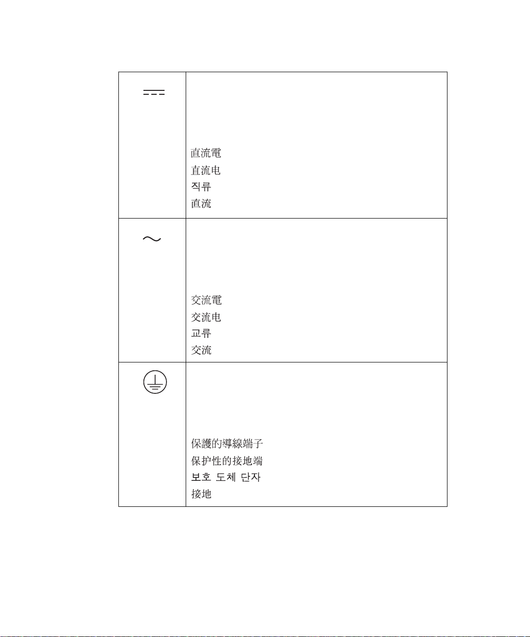
Commonly Used Symbols
Direct current
Courant continu
Gleichstrom
Corrente continua
Corriente continua
Alternating current
Courant alternatif
Wechselstrom
Corrente alternata
Corriente alterna
Protective conductor terminal
Borne du conducteur de protection
Schutzleiteranschluss
Ter m ina le di conduttore con protezione
Borne del conductor de tierra
Page 11

Commonly Used Symbols (Continued )
Frame or chassis terminal
Borne du cadre ou du châssis
Rahmen- oder Chassisanschluss
Ter m ina le di str uttura o telaio
Borne de la estructura o del chasis
Caution or refer to manual
Attention ou reportez-vous au guide
Vorsicht, oder lesen Sie das Handbuch
Prestare attenzione o fare riferimento alla guida
Actúe con precaución o consulte la guía
Caution, hot surface or high temperature
Attention, surface chaude ou température élevée
Vorsicht, heiße Oberfläche oder hohe Temperatur
Precauzione, superficie calda o elevata temperatura
Precaución, superficie caliente o temperatura elevada
Page 12

Commonly Used Symbols (Continued )
Caution, risk of electric shock (high voltage)
Attention, risque de commot ion électri que (haut e tension )
Vorsicht, Elektroschockgefahr (Hochspannung)
Precauzione, rischio di scossa elettrica (alta tensione)
Precaución, peligro de descarga eléctrica (alta tensión)
Caution, risk of needle-stick puncture
Attention, risques de perforation de la taille d’une aiguille
Vorsicht, Gefahr einer Spritzenpunktierung
Precauzione, rischio di puntura con ago
Precaución, riesgo de punción con aguja
Caution, ultraviolet light
UV
Attention, rayonnement ultrviolet
Vorsicht, Ultr a violettes Licht
Precauzione, luce ultravioletta
Precaución, emisiones de luz ultravioleta
Page 13

Commonly Used Symbols (Continued )
1
0
Fuse
Fusible
Sicherung
Fusibile
Fusible
Electrical power on
Sous tension
Netzschalter ein
Alimentazione elettrica attivata
Alimentación eléctrica conectada
Electrical power off
Hors tension
Netzschalter aus
Alimentazione elettrica disat tivata
Alimentación eléctrica desconectada
Page 14

432 Conductivity Detector Information
Intended Use
The Waters® 432 Conductivity Detector can be used for in-vitro diagnostic testing to
analyze many compounds, including diagnostic indicators and therapeutically monitored
compounds. When you de velop methods, follow the “Protocol for the Adoption of
Analytical Methods in the Clinical Chemistry Laborator y,” American Journal of Medical
Tech nol ogy, 44, 1, pages 30–37 (1978). This protocol covers good operating procedures
and techniques necessary to validate system and method performance.
Biological Hazard
When you analyze physiological fluids, take all necessary precaut ions and treat all
specimens as potentially infectious. Precautions are outlined in “CDC Guidelines on
Specimen Handling,” CDC – NIH Manual, 1984.
Calibration
Follow acceptable methods of calibration with pure standards to calibrate methods. Use a
minimum of five standards to generate a standard curve. The concentration range should
cover the entire range of quality-control samples, typical specimens, and atypical
specimens.
Quality Control
Routinely run three quality-control samples. Quality-control samples should represent
subnormal, nor m al, and above-norm al levels of a compound. Ensure that quality-control
sample results are within an acceptable range, and ev aluate precision from day to day and
run to run. Data collected when quality-control samples are out of range may not be valid.
Do not report this data until you ensure that chromatographic system performance is
acceptable.
Page 15

Table of Contents
Preface ....................................................................................... 23
Chapter 1
Introduction .................. ............................. ............................. .......... 26
Chapter 2
Installing the Detector ...................................................................... 30
2.1 Selecting the Installation Site................................................ 30
2.2 Unpacking and Inspection..................................................... 31
2.3 AC Power Connection ........................................................... 32
2.4 I/O Signal Connections......................................................... 35
2.4.1 I/O Signal Desc ri pt ions ....... ..... .... ..... ................... ..... . 35
2.4.2 Powe rLine Controller Connections ............................ 37
2.4.3 Empower and Millennium
32
Connections .................. 39
2.4.4 Data Module Connections ......................................... 44
2.4.5 Chart Recorder Connections..................................... 45
2.4.6 Chart Marker Input Connections................................ 45
2.4.7 Auto Zero Input Connections..................................... 46
2.4.8 Alliance Separatio ns Mo dule Connec tion s ............... . 46
2.5 Making Fluidic Connections.................................................. 48
2.6 Passivating the System......................................................... 53
2.7 Verifying the Detector............................................................ 54
Table of Contents 15
Page 16

Chapter 3
Operating the Detector .................................................................... 56
3.1 Controls and Indicators......................................................... 56
3.2 Startup and Shutdown .......................................................... 61
3.3 Operating Recommendations ............................................... 62
Chapter 4
Performing Ion Analysis ................................................................... 64
4.1 Fundamental Considerations................................................ 64
4.2 Configuring the System......................................................... 68
4.3 Eluents for Ion Analysis......................................................... 69
4.3.1 Preparing Anion Eluent....... ................... ..... ..... .... ...... 70
4.3.2 Preparing Cation Eluent .......... .... ..... ..... ..... ..... .......... 70
4.4 Standards for Ion Analysis .................................................... 70
4.4.1 Preparing Anion Standa rds ......... ..... ................... ..... . 71
4.4.2 Injecting Anion Standards.......................................... 72
4.4.3 Preparing Cation Standard s ............. ..... ................... . 74
4.4.4 Injecting Cati on Stan dar ds........... ..... ..... ..... ..... .......... 76
Chapter 5
Maintenance .................................................................................... 78
5.1 Routine Maintenance............................................................ 78
5.1.1 Replacing the Fuse.................................................... 78
5.1.2 Maintaining the Flow Cell........................................... 79
5.2 Cleaning the Detector Exterior.............................................. 82
5.3 Troubleshooting..................................................................... 82
Table of Contents 16
Page 17

Appendix A
Specifications ................................................................................... 87
Appendix B
Spare Parts......... ..... ..... ..... ..... .... ..... ................... ..... ..... ..... ..... .......... 90
Appendix C
Ion Chromatography Methods .......................................................... 91
C.1 General-Purpose Anion Analysis Using Conductivity
and UV Detection ................................................................ 91
C.1.1 Prepa rin g Eluent ...... ..... ..... ..... .... .................... .... ..... . 93
C.1.2 Prepa rin g Stand ard s .......... ..... ................... ..... .... ..... . 93
C.1.3 Preparing a Sample .................................................. 93
C.1.4 Empower Data Processing Method........................... 94
C.1.5 Method Valid atio n .............. ..... .... ..... ..... ..... ............... 95
C.1.6 Method Linea rity.. ..... ..... ..... ................... ..... ..... .... ..... . 95
C.1.7 Quantita tion Prec ision... ..... ..... .... ..... ..... ..... ............... 97
C.1.8 Method Detection Limits............................................ 97
C.1.9 Quantita tion Accu racy... ..... ..... .... ..... ................... ..... . 98
C.1.10 Analyte Recovery.................................................... 99
C.1.11 Example of Use..................................................... 100
C.1.12 Using Direct UV Detection .................................... 100
C.1.13 Preparing Lithium Borate/Gluconate 50X
Stock Concentrate................................................... 102
C.1.14 Preparing Lithium Borate/Gluconate Eluent.......... 102
Table of Contents 17
Page 18

C.2 Alkali and Alkaline Earth Cations, Ammonium,
and Amines........................................................................ 103
C.2.1 Prepa rin g Elu ent .................... .... ..... ................... .... 104
C.2.2 Prepa rin g Stand ard s .......... ..... ................... ..... .... .... 104
C.2.3 Preparing a Sample ................................................ 105
C.2.4 Empower Data Processing Method......................... 105
C.2.5 Method Detection Limits.......................................... 106
C.2.6 Examples of Use..................................................... 107
C.2.7 Preparing Stock Reagent........................................ 108
Appendix D
Validation Support .......................................................................... 109
Index ..................................................................................... 111
Table of Contents 18
Page 19

List of Figures
1-1 Waters 432 Conductivity Detector.................................................26
1-2 Flow Cell Schematic ......................................................................28
2-1 Rear Panel..................................................................................... 33
2-2 Changing the Voltage Setting........................................................34
2-3 I/O Terminal Strip...........................................................................36
2-4 IEEE-488 Address Switch..............................................................38
2-5 Bus SAT/IN Module (Front Panel).................................................. 40
2-6 Bus SAT/IN to Bus LAC/E Connections.........................................42
2-7 Bus SAT/IN to 432 Detector Connections...................................... 43
2-8 Alliance Separations Module Connections to the 432
Detector Auto-Zero on Inject..........................................................47
2-9 Alliance Separations Module Connections to the 432
Detector Chart Mark on Inject........................................................48
2-10 Fluid Connections.......................................................................... 49
2-11 Cutting Po lymeric Tubing...............................................................50
2-12 Ferrule and Compression Screw Assembly...................................51
2-13 Pulse Dampener............................................................................ 53
3-1 Front Panel ....................................................................................56
4-1 Soda Lime Tube.............................................................................67
4-2 System Configuration for Ion Analysis...........................................68
4-3 Chromatogram of a 7-Anion Standard........................................... 74
4-4 Chromatogram of an 8-Cation Standard........................................77
5-1 Installing Operating Voltage Fuses................................................79
5-2 Flow Cell Assembly....................................................................... 81
C-1 Common Anion Standards ............................................................92
List of Figures 19
Page 20

C-2 Calibration Curves for Chloride, Fluoride, and Bromide ............... 95
C-3 Calibration Curves for Nitrite and Nitrate ...................................... 96
C-4 Calibration Curves for Sulfate and Phosphate ..............................96
C-5 100-mL Injection ...........................................................................97
C-6 Typical Drinking Water, No Dilution Required ............................100
C-7 Direct UV Detection ....................................................................101
C-8 100-ppb Anion Standard .............................................................101
C-9 1-ppm Standard .......................................................................... 103
C-10 25-ppb Cation Standard ..............................................................106
C-11 Typical Drinking Water, No Dilution Required ............................107
C-12 Typical Municipal Wastewater, Diluted 1:50, Overlay
of Duplicate Injections.................................................................. 107
List of Figures 20
Page 21

List of Tables
1-1 Limiting Equivalent Conductance of Ions in Water at 25 °C .........29
2-1 Power Cord Wire Identification .....................................................33
2-2 Nominal Operating Voltage...................................................... 34
2-3 I/O Signal Descriptions ........................................................... 36
2-4 IEEE-488 DIP Switch Setting.................................................. 38
2-5 Bus SAT/IN Cable Connections............................................... 44
2-6 Data Module Signal Cable Connections .................................. 44
2-7 Data Module Chart Mark Cable Connections........................... 45
2-8 Chart Recorder Cable Connections......................................... 45
2-9 Autosampler Chart Mark Cable Connections........................... 46
2-10 Autosampler Auto Zero Cable Connections............................. 46
2-11 Connections for Generating Auto-Zero on Inject...................... 47
2-12 Connections for Generating Chart Mark on Inject.................... 48
3-1 Key Descriptions ...........................................................................58
3-2 Setting the Beep Function....................................................... 60
4-1 Shelf-Life of Standards .................................................................71
4-2 Salts for Anion Standard Concentrates.................................... 72
4-3 Anion Concentrate Dilutions.................................................... 72
4-4 Salts for Cation Standard Concentrates .................................. 75
4-5 Cation Concentrate Dilutions ................................................... 75
5-1 Troubleshooting Guide ..................................................................85
A-1 Operational Specifications ............................................................87
A-2 Mechanical Specifications............................................................ 87
A-4 Electrical Specifications................................................................ 88
A-3 Environmental Specifications........................................................ 88
List of Tables 21
Page 22

A-5 Communications........................................................................... 89
B-1 Spare Parts ...................................................................................90
C-1 Required Instru ment ation ...................................................... .......91
C-1 Analysis Conditions ......................................................................92
C-2 IC Processing Method Using Peak Apex for Retention Time....... 94
C-3 Method Validation......................................................................... 95
C-4 Quantitation Precision................................................................... 97
C-5 Quantitation Accuracy................................................................... 98
C-6 Analyte Recovery.......................................................................... 99
C-1 Required Instru ment ation ...................................................... .....103
C-2 Analysis Conditions.................................................................... 104
C-3 IC Processing Method Using Peak Apex for Retention Time..... 105
List of Tables 22
Page 23

Preface
The Waters 432 Conductivity Detector Operator’s Guide details the procedures for
unpacking, installing, operating, maint ain ing, and troubleshooting the 432 Conductivity
Detector. It also includes appendixes listing specifications and spare parts and describing
validation support.
This guide is intended for use by personnel who need to install, operate, maintain, or
troubleshoot the 432 Detector. This guide assum es an understandi ng of the princip les of
chromatography.
Organization
This guide contains the following:
Chapter 1
Chapter 2
electrical connections.
Chapter 3
general operating instructions.
Chapter 4
for anion and cation analysis.
Chapter 5
tables to aid in problem diagnosis.
Appendix A
Detector.
Appendix B
Appendix C
Appendix D
support .
describes the features and method of operation of the 432 Detector.
describes the procedures for installing the 432 Detector and making fluid and
describes the controls and indicators of the 432 Detector, and provides
describes the system configuration, eluents, and standards recommended
describes simple maintenance procedures and provides troubleshooting
describes the operational specifications and requirements of the 432
lists the recommended spare parts for the 432 Detector.
describes ion chromatography methods.
describes the recommended validation protocols and Waters® validation
Related Documentation
Waters Licenses, Warranties, and Support: Provides software license and warranty
information, describes training and extended support, and tells how Waters handles
shipments, damages, claims, and returns.
23
Page 24

Documentation on the Web
Related product information and documentation can be found on the W orld Wide Web .
Our address is http://www.waters.com
.
Related Adobe Acrobat Reader Documentation
For detailed infor mation about using Adobe® Acrobat® Reader, see the Adobe Acrobat
Reader Online Guide. This guide covers procedures such as viewing, navigating, and
printing electronic documentation from Adobe Acro bat Reader.
Printing This Electronic Docu men t
Adobe Acrobat Reader lets you easily print pages, page ranges, or the entire document by
selecting File > Print. For optimum print quant ity, Waters recommends that you specify a
PostScript
resolution.
®
printer driver for your printer. Ideally, use a printer that supports 600 dpi print
Documentation Conventions
The following conventions can be used in this guide:
Convention Usage
Purple
Italic Italic indicates information that you supply such as variables. It also
Courier
Courier Bold
Underlined Blue I ndi cates hypert ext cross-references to a specific chapter, section,
Keys T he word key refers to a computer key on the keypad or keyboard.
Purple text indicates user action such as keys to press, menu selections, and commands. For example, “Click Next to go to the next
page.”
indicates emphasis and document titles. For example, “Replace
file_name with the actual name of your file.”
Courier indicates examples of source code and system output. For
example, “The SVRMGR> prompt appears.”
Courier bold indicates characters that you type or ke ys you press in
examples of source code. For example, “At the LSNRCTL> prompt,
enter set password oracle to access Oracle.”
subsection, or sidehead. Clicking this topic using the hand symbol
brings you to this topic within the document. Right-clicking and
selecting Go Back from the short c ut menu returns you to the origi-
nating topic. For example, “The detector’s I/O signals are described
in Section 2.4,
Screen keys ref er to the ke ys on the instrument located immediately
below the screen. For example, “The A/B screen key on the 2414
Detector displays the selected channel.”
I/O Signal Connections.”
24
Page 25

P
Convention Usage
… Three periods indicate that more of the same type of item can
optionally follow. For example, “You can store filename1, filename2,
… in each folder.”
>
Notes
Notes call out information that is helpful to the operator. For example:
Record your result before you proceed to the next step.
Note:
Attentions
Attentions provide information about preventing damage to the system or equipment. For
example:
A right arrow between menu options indicates you should choose
each option in sequence. For example, “Select File > Exit” means
you should select File from the menu bar, then select Exit from the
File menu.
Attention:
STO
Cautions
window.
Cautions provide information essential to the safety of the operator. For example:
Caution:
replacement or adjustment.
Caution:
performing maintenance procedures.
Caution:
when operating the system.
To avoid damaging the detector flow cell, do not touch the flow cell
To avoid burns, turn off the lamp at least 30 minutes before removing it for
To avoid electrical shock and injury , unplug the power cord before
To avoid chemical or electrical hazards, observe safe laboratory practices
25
Page 26
Chapter 1 Introduction
Features
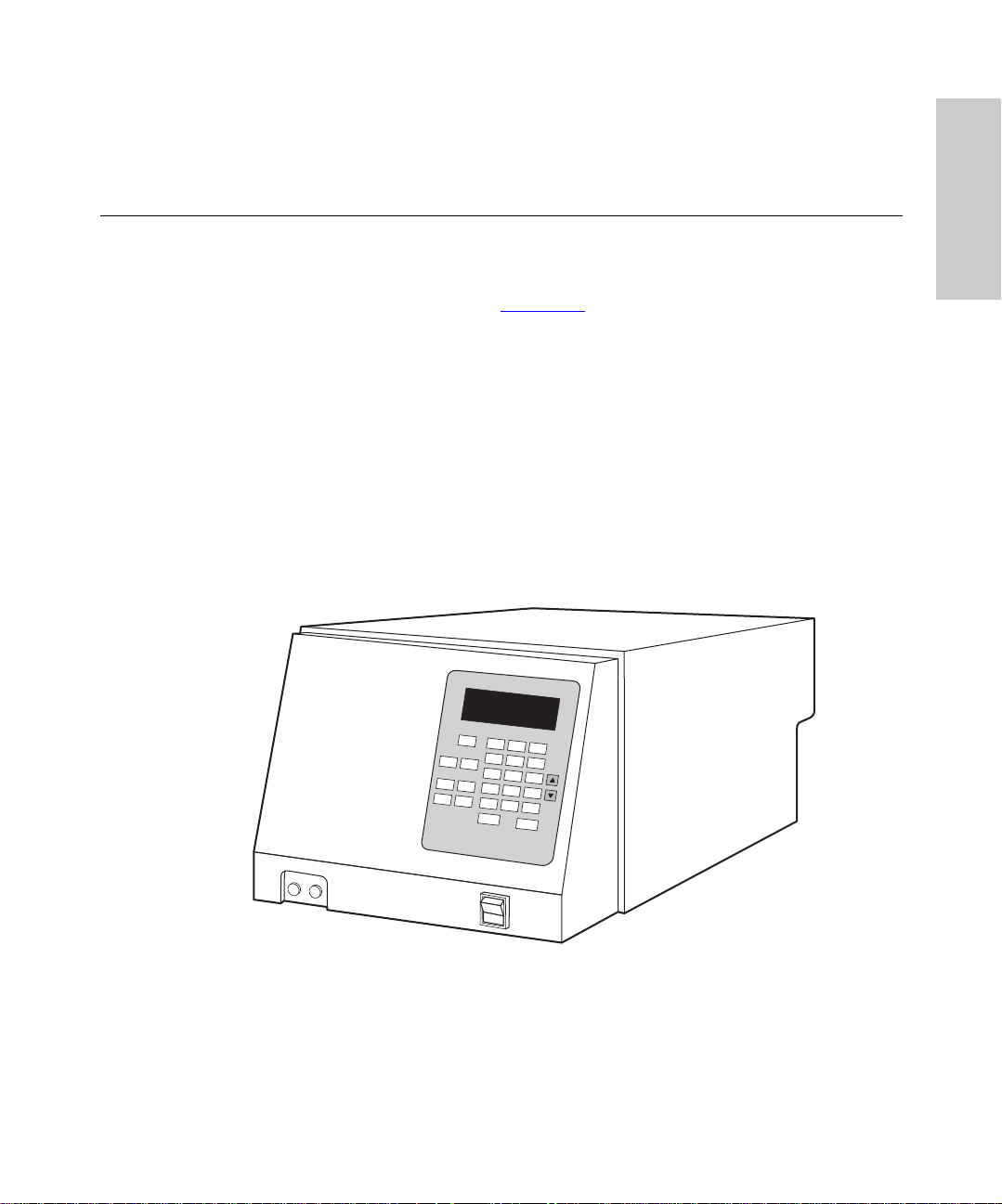
The Waters® 432 Conductivity Detector (Figure 1-1) is specifically designed to be
integrated into chromatographic systems. The following features contribute to its
performance in measuring the conductivity of column eluents:
• Unique 5-electrode flow cell design
• Heat exchanger and a built-in automatic temperature control system for stable
operation
• Auto baseline/auto zero
• External recorder/integrator and chart mark connections
• Three time constant selections
• “Leak-detected” alarm signal
W
aters 432
Conductivity Detector
1
TP01268
IN
OUT
Figure 1-1 Waters 432 Conductivity Detector
26
Page 27

Method of Operation
This section discusses the method of operation of the 432 Detector. Additional descriptive
information appears in these sections:
• Section 2.4.1,
• Section 3.1, Controls and Indicators
• Appendix A, Specifications
Measurement Technique
The 432 Detector responds to all ions present in the flow cell, since all ions in solution
conduct electricity. This allows the 432 Detector to detect a wide variety of sample ions.
The 432 Detector eliminates the eluent’s contribution to conductivity with an electronic
technique called baseline suppression. The detector measures the eluent conductivity and
assigns it a value of zero. Thus, any sample ions appear as positive or negative
measurements, relative to the baseline.
The temperature of an ionic solution affects the conductivity of the ions. Generally, a
solution’s conductivity rises about 2% for every degree Celsius of temperature increase.
The special flow cell heater in the 432 Detector minimizes the effect of ambient
temperature fluctuations on measurement accuracy .
Flow Cell Design
The flow cell in the 432 Detector contains five electrodes connected in a measuring circuit:
two reference electrodes, two detection electrodes, and a guard electrode that provides a
local electrical “ground” (Figure 1-2
set temperature, and then flows through the cell, directly contacting the electrodes. The
5-electrode design permits measurem ent of conduct ivity to be made with a very low
current at the detection electrodes. The low current employed eliminates impedance and
other problems associated with simpler designs, and results in a stable baseline and an
extended range of linearity .
I/O Signal Descriptions
). Column eluent flows through the heater to attain the
1
Introduction 27
Page 28

1
k
G
TP01271
Ion Detection Theory
1= Reference Electrodes
2= Detection Electrodes
3
Figure 1-2 Flow Cell Schematic
2
3= Guard Electrode
Flow Cell Bloc
(heated)
Fluid Outlet
1
The conductance of a solution of known concentration can be calculated using the
following equation:
λC
----------
=
G = measured conductance of the solution, in Siemens
(1 S = ohm
C = concentration in equivalents per 1000 cm
K = length/area of cell (the cell constant)
λ = equivalent conductance in S cm
Table 1-1 lists the equivalent conductances of some common ions.1 Concentrations above
−5
10
to 10−3 N, generally exhibit decreased equivalent conductance due to interionic
effects.
−1
)
10
3–
3
equiv
−1
2
28
Page 29

Table 1-1 Limiting Equivalent Conductance of Ions in Water at 25 °C
Cations
+
H
+
Li
+
Na
+
K
+
Rb
+
Ag
+
NH
4
(CH3)2NH
2+
Hg
2+
Mg
2+
Ca
2+
Ba
2+
Cu
2+
Zn
3+
La
3+
Ce
l
+
349.8 OH
38.6 F
50.1 Cl
73.5 Br
77.8 I
61.9 NO3
73.3 ClO
+
2
51.8 ClO
53.0 IO
−
−
−
−
4
Anions
−
−
−
3
−
4
−
198.6
55.4
76.4
78.1
76.8
71.5
64.6
67.4
54.5
λ
—
1
53.1 Formate 54.6
59.5 Acetate 40.9
63.6 Benzoate 32.4
2
53.6 SO
52.8 CO
69.7 Fe(CN)
−
4
2
−
3
4
−
6
80.0
69.3
111.0
69.8
1. Henry H. Bauer et al., eds. “Instrumental Analysis,” Allyn and Bacon, Boston (1978), p. 115. Reprinted
with permission from the publisher.
Introduction 29
Page 30

Chapter 2 Installing the Detector
This chapter guides you through the following steps in preparing the 432 Detector for
operation in a chromatographic system:
• Selecting an installation site that satisfies the detector’ s power and environmental
requirements
• Unpacking and inspecting the 432 Detector and accompanying items
• Connecting the detector to your AC power supply
• Connecting the detector electrically to the other components of your chromatographic
system
• Connecting the detector inlet to the column and the detector outlet to a waste
receptacle (and, if required, installing the pulse dampener)
• Passivating the detector and other post-column fluid path componen ts
After you have successfully completed this chapter, familiarize yourself with the
information in Section 3.1,
detector, perform the startup procedure described in Section 3.2,
Controls and Indicators. When you are ready to operate the
2.1 Selecting the Installation Site
Operating Environment
The 432 Detector operates in any standard laboratory environment that provides suitable
electrical power and remains within the following ranges:
• Temperatu re: 5 to 35 °C (40 to 95 °F)
• Humidity: 20 to 80%, noncondensing
Install the instrument in a clean area that is free from exposure to:
2
Startup and Shutdown.
• Temperature or humidity extremes, which can be found near direct sunlight, heat
registers, and air conditioning vents
• Strong electromagnetic radiation, such as from large motors or arcing contacts
• Appreciable shock or vibration
Selecting the Installation Site 30
Page 31

Required Space
P
The 432 Detector requires bench space that measures approximately:
• 10 inches (25 cm) high
• 14 inches (34 cm) wide
• 24 inches (60 cm) deep
Make sure that air can circulate freely through the ventilation slots on both
STO
Attention:
side panels.
Power Requirements
The 432 Detector requires:
• One properly grounded AC voltage outlet.
• Correct voltage and fuse selections as shown in Table 2-2
2.2 Unpacking and Inspection
Unpacking
The 432 Detector is shipped in one carton that contains the following items:
• Waters 432 Conductivity Detector
• Startup Kit
• Validation certificate
• Waters 432 Conductivity Detector Operator’s Gui de
• Packing list
• Declaration of conformity
2
.
If you purchased the 432 Detector as part of an ion/liquid chromatograph system, a
Note:
Waters representative will perform the installation and startup.
To unpack the 432 Detector :
1. Locate the packing list.
2. Unp ack the contents of the shipping carton and check the contents against the
packing list to make sure that you received all items.
3. Check the contents of the Startup Kit against the Waters 432 Conductivity Detector
Star tup Kit List.
4. Save the shipping carton for future transport or shipment.
Installing the Detector 31
Page 32

Inspection
Inspect all items. If you find any damage or discrepancy , immediately contact the shipping
agent and Waters. For more information about the instrument warranty, refer to Waters
Licenses, Warranties, and Support.
If the shipment is complete and undamaged, record the installation date and serial number
of the 432 Detector in the spaces provided in Appendix B,
2.3 AC Power Connection
Spare Parts.
Caution:
the voltage selector in the power connector is set correctly to match the available AC
power source, and that the correct fuses are installed before you apply AC power.
To avoid a potential fire hazard and damage to the 432 Detector, make sure that
Power Cord
The power connector is located on the lower-r ight co rner of the rear panel, as shown in
Figure 2-1
Table 2-1
. If a power pl ug other than the one supplied is needed for your location, consult
and observe the existing applicable regulations.
2
AC Power Connection 32
Page 33

IEEE DIP
Switch Cover
Figure 2-1 Rear Panel
Table 2-1 Power Cord Wire Identification
Wire (USA) Wire (International) Connection
Black Brown Hot
White Blue Neutral
Green Green/Yellow Ground (Earth)
2
The 432 Detector can be adapted to operate within two voltage ranges at 50 or 60 Hz.
Table 2-2
describes these voltage ranges and the fuse value that is appropriate to each.
Installing the Detector 33
Page 34

Table 2-2 Nominal Operating V oltage
Nominal Voltage (VAC) Fuse
100/120 T 2A
220/240 T 1A
Required Material
You need a flat-blade screwdriver to perform this procedure.
Procedure
Caution:
and unplug the power cord.
To change the operating voltage setting:
1. Remove the power cord from its connector on the rear panel of the controller and
2. Remove the voltage selection barrel and locate the correct voltage setting
3. Reinstall the voltage selection barrel so the desired voltage setting appears through
To avoid the possibility of electrical shock, turn off the front panel power switch
pry open the power connector cover with a flat-blade screwdriver.
(Figure 2-2
the window when you close the power connector cover (Figure 2-2
).
).
2
Voltage Settings
Figure 2-2 Changing the Voltage Setting
4. Determine if you need to change the fuses (see Table 2-2
with two 2-A fuses installed for 100/120 volt operation. If you operate the unit on
220/240 volt power, change the fuse as outlined in Section 5.1.1, Replacing Fuses.
5. Reins tall the power connector cover and the power cord.
). All units are supplied
AC Power Connection 34
Page 35

2.4 I/O Signal Connections
P
The 432 Detector is usually installed as an integral part of a data collection system. You
can control the 432 Detector either locally from the keypad on the front panel or remotely
from a PowerLine™ controller, such as the Waters 600S.
This section describes the detector’s I/O signals and how they connect to the following
devices:
• PowerLine controller
• Empower™ or Millennium®
• Data module
• SAT/IN™ module
• Chart recorder
• Device signalling the Chart Marker input
• Device signalling the Auto Zero input
32
soft wa r e
2
To meet the regulatory requirements of immunity from external electrical
STO
Attention:
disturbances that may affect the performance of this instrument, do not use cables longer
than 9.8 feet (3 meters) when connecting to the screw-type barrier termi nal strips. In
addition, ensure you always connect the shield of the cable to chassis ground at one
instrument only.
2.4.1 I/O Signal Descriptions
The 432 Detector rear panel has an IEEE-488 connector for communication with a
PowerLine controller, and a terminal strip (Figure 2-3
signals are described in Table 2-3.
) for the input/output signals. These
Installing the Detector 35
Page 36

+
+
–
+
–
+
–
+
–
t
INT
Int
–
+
REC
Rec
–
LEAK
Leak
+
MARKER
Marker In
IN
–
MARKER
Marker Ou
OUT
+
AUTO ZERO
Auto Zero
–
Figure 2-3 I/O Terminal Strip
Table 2-3 I/O Signal Descriptions
Terminal Pairs Function
2
Rec (+ and –)
Recorder output – A 10-mV full-scale analog output signal appears
on these terminals. The measurement range is deter mined by the
product of the Base Range and Sensitivity settings: for example,
500 µS (base range) x 0.005 (sensitivity) = 2.5 µS full sca le.
Int (+ and –)
Integrat or ou tp ut – A 1-V fu ll-scale analo g output signal appears on
these terminals. The measurement range is selectable:
10, 50, or 100 µS full scale.
Marker Ou t
Marker output – A 1-second contact closure signal appears on these
terminals when either of the following events occurs:
Leak
Auto Zero
(+ and –)
• The Char t Mark key on the keypad is pressed
• A contact closure signal occurs between the Marker In terminals
Leak Alert output – A contact closure signal appears on these termi-
nals if a leak is detected inside the detector.
Auto Zero input – The voltage at the Recorder and Integrator output
terminals is set to the user-selected balance offset level when a
contact closure occurs between these terminals.
Marker I n
(+ and –)
Marker input – A chart mark (~0.5 mV for 3 seconds) is added to the
Recorder output signal when a contact closure signal appears
between these terminals.
I/O Signal Connections 36
Page 37

Required Material
To connect cables to the I/O terminals, use a small flat-blade screwdriver.
Other Rear Panel Connections and DIP Switch
In addition to the I/O terminal strip, the rear panel also contains the following items:
• IEEE-488 connector – Communication bus for use with a Waters PowerLine system
controller, such as the Waters 600S.
• DIP switch – Sets the IEEE-488 address seen by the system controller.
• Ground lugs – Used to connect the 432 Detector to an earth ground connection and
also used as a chassis ground connection to other system instruments.
2.4.2 PowerLine Controller Connections
The 432 Detector can be programmed remotely by a PowerLine controller (such as the
Waters 600S) via the IEEE-488 data communications bus.
Required Material
You need a 2.5-mm Allen wrench to connect to the 432 Detector.
Procedure
To connect the 432 Detector to a PowerLine controller:
2
1. Turn off the PowerLine controller and the 432 Detector.
2. Plug one end of the IEEE-488 cable (included in the Start up K it) into the bus
connector on the rear panel of the 432 Detector (Figure 2-1
the cable into the bus connector on the PowerLine controller.
3. Remove the DIP switch cov er (Figure 2-1
4. R efer to Table 2-4 to set the DIP switches on the rear panel of the 432 Detector
(Figure 2-4
5. Afte r you set th e DIP swi tc hes, re in stall the DIP switch cover.
To operate the 432 Detector in local mode, press the front panel
Note:
illuminated light above the key will go out.
) to a unique IEEE-488 address between 2 and 29.
) using a 2.5-mm Allen wrench.
) and the other end of
Remote
Installing the Detector 37
key. The
Page 38

4
2
1
1 2 3 4 5
OFF
(Address 8 Shown)
Figure 2-4 IEEE-488 Address Switch
The IEEE-488 address DIP switch employs positive logic to determi ne the addre ss of the
432 Detector from the switch settings. Table 2-4
Table 2-4 IEEE-488 DIP Switch Setting
IEEE-488
Address
2 OFF ON OFF OFF OFF
3 ON ON OFF OFF OFF
4 OFF OFF ON OFF OFF
5 ON OFF ON OFF OFF
6 OFF ON ON OFF OFF
7 ON ON ON OFF OFF
8 OFF OFF OFF ON OFF
9 ON OFF OFF ON OFF
10 OFF ON OFF ON OFF
11 ON ON OFF ON OFF
12 OFF OFF ON ON OFF
13 ON OFF ON ON OFF
14 OFF ON ON ON OFF
15 ON ON ON ON OFF
16 OFF OFF OFF OFF ON
17 ON OFF OFF OFF ON
18 OFF ON OFF OFF ON
19 ON ON OFF OFF ON
1 2 3 4 5
DIP Switch Set t ings
8
16
Switch 5Switch 1
shows the settings for valid addresses.
2
I/O Signal Connections 38
Page 39

Table 2-4 IEEE-488 DIP Switch Setting (Continued)
IEEE-488
Address
20 OFF OFF ON OFF ON
21 ON OFF ON OFF ON
22 OFF ON ON OFF ON
23 ON ON ON OFF ON
24 OFF OFF OFF ON ON
25 ON OFF OFF ON ON
26 OFF ON OFF ON ON
27 ON ON OFF ON ON
28 OFF OFF ON ON ON
29 ON OFF ON ON ON
1 2 3 4 5
DIP Switch Set t ings
PowerLine Operation
Under PowerLine control, the 432 Detector is recognized as a 431 Detector and it retains
the functionality of the 431 Detector with the following differences:
• The Balance field on the detector setup page of the PowerLine controller affects the
Integrator Balance and the Integrator Output only.
• When you press the Setup key on the controller, t he selected Balance value is sent to
the 432 Detector from the PowerLi ne controller. However, the 432 Detector output
does not change to the selected balance until the detector is autozeroed by a contact
closure at the Auto Zero input terminals on the rear panel (remote or local mode) or
when you press the Auto Zero key on the front panel (local mode only).
2
Under PowerLine control, the 432 Detector retains the full functionality of local mode
operation, except for the following differences:
• The Recorder Sensitivity ranges of 0.0002 and 0.0001 are not accessible.
• The Integrator Sensitivity ranges are not accessible.
• The 432 Detector does not automatically perform an Auto Zero after an Auto Base
routine has occurred.
2.4.3 Empower and Mille nn ium32 Connections
Empower and Millennium32 software perform data acquisition, processing, and
management of chromatographic information. This software requires the detector’ s analog
signal to be converted to a digital form.
Installing the Detector 39
Page 40

Empower and Millennium32 are menu-driven applications specifically designed by Waters
for chromatographers. Use the software to:
• Acquire data
• Process d a ta
• Generate and print reports
• Store information (or data) in a central area and share this information with users who
have pr oper se cu rity acce ss
To connect the 432 Detector to an Empower or Millennium
32
computer, be sure to:
• Connect the Bus Satellite Interface (SAT/IN) module to the Bus Laboratory
Acquisition and Control/Environment (LAC/E™) card in the Empower computer,
32
Millennium
computer, acquisition client, or LAC/E32.
• Connect the 432 Detector to the Bus SAT/IN module (Channel 1 or 2).
• Remove the IEEE-488 cable from the rear panel of the 432 Detector, if it is
connected.
The 432 Detector is in local m ode when it is connec t ed to an Empower and Mille nnium
computer.
Bus S AT/IN Module
The Waters Bus SAT/IN module, shown in Figure 2-5, translates analog signals into digital
form. It then transmits these digital signals to the Bus LAC/E card inside the workstation,
acquisition client, or LAC/E
32
.
2
32
Waters SAT/IN Module
CHANNEL 1 CHANNEL 2
EVENTS
CH1
IN INOUT OUT
+ –
1 2 3 4 5 6 7 8
CH2
+ –
Figure 2-5 Bus SAT/IN Module (Front P anel)
CH1CH
OK
2
I/O Signal Connections 40
Page 41

To prevent damage to the unit, always disconnect the power cord at either the wall
Note:
outlet or the power supply before you attach or remove the power connection to the Bus
SAT/IN module. The Bus SAT/IN module does not have a power switch.
Connecting the Bus SAT/IN Module to the Bus LAC/E Card
The Bus SAT/IN module connects to the Bus LAC/E through an I/O distribution box, as
shown in Figure 2-6
To connect the Bus SAT/IN module to the Bus LAC/E card:
.
1. Use the I/O distr ibution cable to connect the I/O distribution box to the 9-pin I/O
distr ibut ion po rt on the Bus L AC/E car d a t the b ack of the Millennium
2. Use a serial cable to connect the data terminal on the back of the Bus SAT/IN to a
port of the I/O distribution box.
3. Configure the serial port for the Bus SAT/IN module as described in the Empower or
Millennium
32
installation and configuration guides.
32
computer.
2
Installing the Detector 41
Page 42

I/O Distribution
Cable
I/O Distribution Port (9-pin)
of Bus LAC/E Card
SAT/IN Module
Rear Panel
I/O Distribution Box
BCD
DATA
PWR
Serial Cable
AC to DC Converter
Modified Modular
Jack Connections
Connect SAT/IN
to Port 1 on the
I/O Distribution Box
2
Figure 2-6 Bus SAT/IN to Bus LAC/E Connections
I/O Signal Connections 42
Page 43

Connecting the Bus SAT/IN Module to the 432 Detector
P
te
Black
The Bus SAT/IN module connects to the 432 Detector as shown in Figure 2-7. Refer to the
procedure following the figure and Table 2-5
for complete details.
STO
Waters SAT/IN Module
Attention:
To prevent damage to the unit, do not plug in the power cord of the Bus
SAT/IN module until you perform all of the procedures described in the Waters B u s
SAT /IN Mo dule Installation Guide.
Waters 432 Detector
Whi
Red
Black
+
INT
–
+
REC
–
LEAK
+
MARKER
IN
–
EVENTS
CH1
CHANNEL 1 CHANNEL 2
IN INOUT OU T
+ –
1 2 3 4 5 6 7 8
CH2
+ –
CH1CH
OK
2
MARKER
OUT
+
AUTO ZERO
–
2
TP01264
Figure 2-7 Bus SAT/IN to 432 Detector Connections
To connect the 432 Detector to the Bus SAT/IN module:
1. Connect the white wire of the analog cable (included with the Bus SAT/IN module) to
the Int + terminal on the rear panel of the 432 Detector. Connect the black wire to
the Int – terminal.
2. Con nect the other end of the cable to either the Channel 1 or Channel 2 connector
on the front panel of the Bus SAT/IN module.
Installing the Detector 43
Page 44

3. Connect the Event In terminals of the channel you chose in the previous step to the
P
Inject St a rt output signal of the Waters Alliance
Waters 717plus (or equivalent) Autosampler.
4. Remove the IEEE-488 cable from the rear panel of the 432 Detector, if it is
connected.
The connections from the 432 Detector to the Bus SAT/IN are summarized in Table 2-5.
Table 2-5 Bus SAT/IN Cable Connections
®
solvent delivery system or the
432 Detector I/O
Connector Terminal
Int (+ ) White wire
Int (–) Black wire Channel 1 or 2
Bus SAT/IN
Cable
2.4.4 Data Module Connections
This section describes how to connect the analog output signal from the 432 Detector to
the Waters 746 Data Module.
Attention:
STO
electrical disturbances that may affect the performan ce of this instrument, do not use
cables longer than 9.8 feet (3 meters) when connecting to the screw-type barrier terminal
strips. In addition, ensure you always connect the shield of the cable to chassis ground.
Analog Signal
To send the analog output signal from the 432 Detector to a Waters data module, connect
the signal cable in the 432 Detector Startup Kit as described in Table 2-6
Table 2-6 Data Module Signal Cable Connections
Wire
Remember to meet the regulatory requirement s of immunity from external
432 Detector I/O
Connec tor Terminal
Bus SAT/IN
Connector
2
.
746
Terminal
Red Int (+) (+)
Black Int (– ) (–)
Shield Ground lug None
Marker Out Signal
The Marker Out terminals of the 432 Detector provide a contact closure output signal
when either of the following events occurs:
• Chart Mark key is pressed
• Marker In terminals are shorted to gether
I/O Signal Connections 44
Page 45

Use the signal to start a Waters 746 Data Module by connecting a signal cable to the
module’s data cable (Table 2-7
Table 2-7 Data Module Chart Mark Cable Connections
).
432 Detector I/O
Wire
Either wire Marker Out Join to both Remote Start
Other wire Marker Out Green wire
Connector
Terminal
2.4.5 Chart Recorder Connections
To connect the 432 Detector to a chart recorder:
1. Attach the Recorder cable (see Appendix B,
output terminals, as indicated in Table 2-8
2. Con nect the cable shield to the ground lug on the 432 Detector rear panel.
3. Con nect the other end of the cable to the 10-mV input terminals on the chart
recorder, as indicated in Table 2-8
Table 2-8 Chart Recorder Cable Connections
Wire
Red Rec (+) Pen (+)
Black Rec (–) Pen (–)
432 Detector I/O
Connector Terminal
746
Cable
wires (white and red)
2
Spare Parts) to the 432 Detector REC
.
.
Chart Recorder
Terminal
2.4. 6 Chart Marker Input Connections
The 432 Detector accepts a chart mark (start inject) signal from the following devices:
• Waters 717plus Autosampler
• Any other device that provides a compatible switch closure
Waters 717plus Autosampler
To connect the 432 Detector to a Waters 717/717plus Autosampler , connect a signal cable
as indicated in Table 2-9
.
Installing the Detector 45
Page 46

Table 2-9 Autosampler Chart Mark Cable Connections
432 Detector I/O
Connector Terminal
Marker In (+) Either Inject Start ter m inal of a pair
Marker In (–) Other Inject Start terminal of the same pair
2.4.7 Auto Zero Input Connections
The voltage at the Recorder and Integrator outputs is set to the user-selected balance
offset level when a contact closure occurs between the Auto Zero terminals. This section
describes how to connect the 432 Detector to the following devices (so that an auto zero
occurs at the injection point):
• Waters 717plus Autosampler
• Any other device that provides a compatible switch closure
Waters 717plus Autosampler
To connect the 432 Detector to a Waters 717plus Autosampler, connect a signal cable as
indicated in Table 2-10
Table 2-10 Autosampler Auto Zero Cable Connections
432 Detector I/O
Connector Terminal
.
Autosampler
Terminal
2
Autosampler
Terminal
Auto Zero (+) Either Inject Start ter m inal of a pair
Auto Zero (–) Other Inject Start terminal of the same pair
2.4.8 Alliance Separations Module Connections
Connect the detector to Waters Alliance Separations Modules, when it is not under the
control of the Millennium
• Auto-Zero on inject
• Chart mark on inject
• Method start
Generating Auto-Zero on Inject
To generate the Auto-Zero function on the 432 Detector at the start of an injection, make
the connections summarized in Table 2-11
32
softwa re, to per fo rm the foll o w i n g tasks:
and illustrated in Figure 2-8.
I/O Signal Connections 46
Page 47

Table 2-11 Connections for Generating Auto-Zero on Inject
+
–
+
–
+
–
+
–
INT
REC
LEAK
MARKER
IN
MARKER
OUT
AUTO ZERO
+
–
+
–
+
–
+
–
t
Alliance Separations Modules
(B Inputs and Outputs)
432 Detector (A Inputs)
Pin 1 Inject Start Auto-Zero (+)
Pin 2 Inject Start Auto-Zero (–)
Before you can generate an Auto-Zero from an Alliance Separations Module, you must
configure the Auto-Zero signal at the 432 Detector front panel. The default Auto-Zero
signal is Low.
Waters All iance
B (Inputs and Outputs)
Inject Start +
Inject Start –
Ground
Stop Flow
Stop Flow –
Hold Inje c t 1+
Hold Inject 1
Hold Inject 2 +
Hold Inje c t 2
Ground
Chart Ou t
Chart Out
+
+
–
–
–
Waters 432 Detector
A (Inputs)
1 Inject Start +
2 Inject Start -
3 Ground
4 Lamp On/Off +
5 Lamp On/Off -
6 Chart M a rk +
7 Char t M ark -
8 Ground
9 Auto-Zero +
10 Auto-Zero -
Int
Rec
Leak
Marker In
Marker Ou
Auto Zero
2
Figure 2-8 Alliance Separations Module Connections to the 432 Detector
Generating Char t Mark on Inject
To generate the chart mark function at the start of an injection, make the connections
summarized in Table 2-12
Auto-Zero on Inject
and illustrated in Figure 2-9.
Installing the Detector 47
Page 48

Table 2-12 Connections for Generating Chart Mark on Inject
+
–
+
–
+
–
+
–
INT
REC
LEAK
MARKER
IN
MARKER
OUT
AUTO ZERO
+
–
+
–
+
–
+
–
t
Alliance Separations Modules
(B Inputs and Outputs)
432 Detector (A Inputs)
Pin 1 Inject Start Marker In (+)
Pin 2 Inject Start Marker I n (–)
Before you can generate a chart mark from an Alliance Separations Module, you must
configure the chart mar k signa l at the front panel. The default chart mark signal is Low.
Waters All iance
B (Inputs and Outputs)
Inject Start +
Inject Start –
Ground
Stop Flow
Stop Flow –
Hold Inje c t 1+
Hold Inject 1
Hold Inject 2 +
Hold Inje c t 2
Ground
Chart Ou t
Chart Out
+
+
–
–
–
Waters 432 Detector
A (Inputs)
1 Inject Start +
2 Inject Start -
3 Ground
4 Lamp On/Off +
5 Lamp On/Off -
6 Chart M a rk +
7 Char t M ark -
8 Ground
9 Auto-Zero +
10 Auto-Zero -
Int
Rec
Leak
Marker In
Marker Ou
Auto Zero
2
Figure 2-9 Alliance Separations Module Connections to the 432 Detector
Chart Mark on Inject
2.5 Making Fluidic Connections
Fluid lines to a column and waste container connect to the front of the 432 Detector, as
shown in Figure 2-10
. To make these connections:
• Cut the tubing.
• Assemble compression fittings and ferrules.
• Connect the tubing to the detector.
Making Fluidic Connections 48
Page 49

This section will guid e you through each of these pr ocedures.
P
STO
Attention:
Conductivity detection is sensitive to flow rate fluctuations. If you use a
non-Waters pump or a Waters pump without the SILK microflow compensation algorithm,
you must install the pulse dampener kit supplied in the Startup Kit for optimum
performance. Refer to the installation procedure in this section.
W
aters 4
3
2
o
n
ductivity Dete
O
Out to Waste (18 inches,
0.009-inch I.D.)
U
T
0.009-inch ID)
c
to
r
In from Column
In From Column
C
IN
Out To Waste (18 inches.
Figure 2-10 Fluid Connections
2
Cutting Stainless Steel Tubing
You need the following tools to cut stainless steel tubing:
• A file with cutting edge
• Two cloth- or plastic-covered pliers
To cut the tubing:
1. Meas ure the length of 1/16-inch OD, 0.009-inch ID, stainless steel tubing you need
to make the following connections:
• Column to the detector inlet
• Detector outlet to a suitable waste container
2. Use a file with a cutting edge to scribe the circumference of the tubing at the desired
length.
3. G rasp the tubing on both sides of the scribe mar k with cloth-covered pliers. Gently
work the tubing back and forth until it separates.
4. File the ends smooth.
Installing the Detector 49
Page 50

Cutting Polymeric Tubing
Waters chromatography systems are supplied with a tubing cutter (similar to the one in
Figure 2-11
procedure for using the tubing cutter.
Note:
cuts leave unswept dead volumes at the connection junction due to the poor fit of the
tubing against the connector or port.
To cut a length of polymeric tubing:
1. Estima te the length of tubing required to connect the componen ts. Allow slack so
2. Insert the tubing into the cutter so that the tubing extending from the metal side is
) to facilitate cutting polymeric tubing. This section presents the recommended
To avoid bandspreading caused by angled cuts, always use a tubing cutter. Angled
that the tubing is not pulled tightly around sharp corn ers.
the length required. Use the proper hole to have a snug enough fit so that the tubing
is not flexed by the blade when you cut it.
2
Figure 2-11 Cutting Polymeric Tubing
3. Pres s down on the razor blade to cut the tubing (Figure 2-11
tubing that extends from the clear side of the cutter.
4. Inspec t the cut for burrs or scratches and for the perpendiculari ty of the cut.
). Discard the excess
Assembling Compression Fittings
To assemble each compression fitting:
1. Slide the com pression screw over the tubing end, followed by the ferrule
(Figure 2-12
2. Mount the ferrule with its taper end facing the end of the tubing (Figure 2-12
).
Making Fluidic Connections 50
).
Page 51

Compression
Compression
Screw
Screw
0.009-inch I D Tubing
0.009-inch I.D. Tubing
(0.23 mm)
(0.23 mm)
Figure 2-12 Ferrule and Compression Screw Assembly
Ferrule
Ferrule
Connecting to the 432 Detector
To make connections at the column outlet and detector inlet, and at the detector outlet:
1. Insta ll a compression screw and then a ferrule on the length of 0.009-inch tubing
from the column outlet. Use stainless steel fittings on stainless steel tubing and
PEEK fittings on PEEK tubing.
If you are using a column with 1/4–28 end fittings and there is a length of
Note:
tubing with 1/4–28 fittings on each end, use the 1/4–28 to Z-detail adapter (included
in the Startup Kit) to connect this tubing to the tubing that leads to the detector inlet.
The Waters IC-Pak C column comes supplied with a length of tubing that has a
1/4–28 fitting on one end (column outlet) and a Waters compression screw and
ferrule on the other end (detector inlet).
2
2. Push the free end of the tubing as far as it will go into the IN fitting on the 432
Detector. While you hold it there, use a 5/16-inch open-end wrench to tighten the
compression screw 3/4-turn past finger-tight.
The 432 Detector and IC-Pak series of columns have very deep ferrules.
Note:
3. Remove the compression screw and tubing from the connection and verify that fluid
can flow freely.
4. Reconnect the tubing to the IN fitting, making sure to push the tubing all the way into
the fitting.
5. Install a ferrule on an 18-inch length of 0.009-inch tubing and connect it to the OUT
connection on the 432 Detector. Use stainless steel fittings on stainless steel tubing
and PEEK fittings on PEEK tubing.
6. Place t he other end of the tube in a waste container. If you are using any Teflon
tubing, attach it after the stainless steel or PEEK tubing.
Installing the Detector 51
Page 52

Installing the Pulse Dampener
To achieve the best performance from the 432 Detector in a chromatographic system with
a non-Waters pump, Breeze™ software, or Waters HPLC 515 Pump, you must install the
pulse dampener kit supplied in the Startup Kit. The pulse dampe ner is not required if you
are using a Waters 2695 Separations Module.
To install the pulse dampener betwee n the pump and the injector:
1. Assemble the pulse dampener (Figure 2-13
dampener kit.
2. Con nect the large-ID (0. 020-inch) tubing to the pump outlet using a stainless steel
compression screw and ferrule.
3. Con nect the small-ID (0.009-inch) tubing to the injector inlet using a stainless steel
compression screw and ferrule.
4. Disconnect the tubing from the injector inlet.
5. Pum p AST M Type I reagent water at £ 2 mL/min through the pulse dampener
assembly until you see a constant stream exiting from the restrictor assembly outlet
line.
6. Reconnect the tubing to the injector inlet.
) using the instructions in the pulse
2
Making Fluidic Connections 52
Page 53

P
y
y
0.020-inch I.D.
i
r
0.009-inch I D
Tubing
F
Restrictor
Assembly
0.020-inch I D
Tubing
Tubing
0.009-
Tubing
nch I.D.
From Pum p
rom Pum p Union To Injector
Low Pressure
Low Pressure
Filter Assembly
Filter Assembl
Figure 2-13 Pulse Dampener
2.6 Passivating the System
Union
To Injecto
2
Restrictor
Assembl
STO
Passiv ating the system removes potential contamination from the wetted surfaces of all
system components. Perform pas sivation on a new system, and subsequently, whenever
you suspect that contamination may have occurred. See Section 5.3,
help diagnosing performance problems.
Use this procedure for Waters hardware only. For other equipment, check with the
manufacturer before you continue with this procedure.
Attention:
the pump seals before you passivate. Use the new pump seals supplied in the Startup Kit
and refer to the replacemen t procedure in the pump manual.
If you are installing the 432 Detector into an existing Waters system, replace
Installing the Detector 53
Troubleshooting, for
Page 54

To passivate the system:
1. Rep lace the column with a union fitting.
2. If the system is not new, flush it thoroughly with ASTM Type I reagent water to
remove any residual solvents or salts.
3. Con nect the power cord to the 432 Detector and plug the other end into an AC
power outlet. Push the 432 Detector power switch to tur n on the instrum ent .
Caution:
when you are using solvents.
4. Prime the pump with 6 N nitric acid (HNO
20 minutes to passivate all the wetted parts of the detector. Press the Clear key to
stop the overrange alarm.
5. St op the pump.
6. Remove the inlet line from the nitric acid and place it in ASTM Type I reagent water .
7. Flush the system using one of the following methods:
• Prime and start the pump, then flush it with ASTM Type I reagent water at
1.2 mL/min until you observe a consistent reading of less than 20 µS (base range
set to 50 µS).
• Flush the system overnight with 100% methanol at a reduced flow rate. By the
next morning the system will be passivated and ready for use.
If you are using a pump with seal-wash capability, skip step 8.
Note:
8. Use a syr inge to flush the back of the pump seals and pistons by slowly running
about 5 mL of water into the top hole in the baseplate of the pump heads. Place a
tissue under the baseplates to absorb the water .
9. Set the pump flow rate to 0.0 mL/mi n. It is not nec essary to turn off the 432 Dete ctor
unless it will be idle for an extended period (14 days).
To avoid chemical hazards, alwa ys wear safety glasses and gloves
) and run it at a flow rate of 1.2 mL/min for
3
2
For best results, alw ays leave the power on to main t a in c e ll temperature ; it takes a
minimum of 2 to 3 hours once the detector is turned on to equilibrate the flow cell at the
selected operating temperature.
2.7 Verifying the Detector
This procedure is a guideline for verifying that the detector works correctly within its
expected operational range. The detector is calibrated before shipping, and recalibration is
not normally required.
Verifying the Detector 54
Page 55

Verify the detector when any of these conditions apply:
• When you replace the flow cell
• To verify accuracy
• When you make adjustments
Calibration Procedure
You need solution of 1 mM potassium chloride (KCl) to calibrate the detector.
Note:
Waters suggests one of its Technical Service Representatives perform this
Note:
procedure.
1. Turn on the 432 Detector and set the temperature control to 35 °C. Allow 2 to 3
hours for the temperature in the flow cell to equilibrate.
2. Set the base range to 200 µS.
3. Set the Filter Time Response to Fast.
4. Pump 1 mM KCl solution through the detector (without a column in place).
5. Verify that the front panel output is 147 µS ± 5 µS.
2
Installing the Detector 55
Page 56

Chapter 3 Operating the Detector
This chapter contains:
• A description of front panel controls and displays
• Procedures for starting up, shutting down, and long-term storage
• Recommended operating practices
3.1 Controls and Indicators
Figure 3-1 illustrates the controls and indicators on the front panel of the 432 Detector.
Waters 432
Conductivity Detector
274 500 0.0005
CONDUCT
( S/cm)
BASE
( S/cm/FS)
3
SENS
IN OUT
Auto
Base
Base
Range
Resp.
Figure 3-1 Front Panel
Remote
Chart
Mark
89
56
23
.
Clear
EnterShift
Auto
Zero
Sens.
Range
Bal.
Temp. Pol.
7
4
1
0
ON
OFF
Controls and Indicators 56
Page 57

Power Switch
The power switch ( located in the lower-right corner of the front panel) controls power to the
432 Detector. Upon startup, an initialization routine verifies the data in ROM memory, tests
RAM memory function, and checks for any internal leakage or an eluent conductivity
over-range condition.
Display
The display shows instrument status and parameter values in two 20-character lines of
text. Upon startup, Waters 432 Self Check appears briefly. If any error conditions are
detected during start up or normal operation, the appropriate error message is displayed.
The main screen shows the measured conductivity, as well as the base range and
sensitivity settings. When you set an operating parameter, the display shows the selected
or entered value.
Error Messages
A corresponding error message is displayed if one of the following conditions occurs:
• ROM/RAM error (checked during startup only)
Error: ROM/RAM
• Leakage detected
Error: Leak
3
• Temperature control fail ure
Error: Temp
• Over-range (above base range setting)
Error: Over Range
• Overflow (above 10,000 µS)
Error: Over Flow
Press the Clear key to clear an error alarm and message. For a continuing error condition,
the error message remains after the audio alarm is cleared.
Keypad
Use the keypad to control the operation of the 432 Detector. Table 3-1 describes the
function of each key.
Operating the Detector 57
Page 58

Three keys (Balance, Sensitivity Range, and the numeral 1) perform an alternate
Note:
function when they are preceded by the Shift key.
Table 3-1 Key Descriptions
Key Function
Remote key: Toggles betwee n local and remote operating mode s. In
Remote
Pol.
Base Range
Sens.
Range
remote mode, the light above the key is on and all other front panel
controls are disabled.
Polarity key: Toggles the polarity of the signal to the external chart
recorder and integrator. When positive polarity is selected, the light
above the key is illuminated.
Base Range key: Sets the base sensitivity range of the 432 Detector to
the appropriate value for the eluent being used. The base sensitivity is
set to one of ten steps, from 10 µS (maximum gain) to 10,000 µS, using
the Up and Down keys or the numeric keypad.
Sensitivity Range key: Sets the sensitivity range multiplier of the 432
Detector. The sensitivity range has twelve steps, from 0.0001 (maximum
sensitivity) to 1.0 (avai lable onl y with 100µS multiplier setting), and is set
using the Up and Down keys or the numeric keypad. The 10-mV
full-scale recorder response is calculated by multiplying the Base Range
by the Sensitivity Range to obtain a value of “x” µS / 10 mV FS. The
recorder range is 1 to 0.0001 for the 100 µS setting and 0.1 to 0.0001 for
the two lower settings.
3
Bal.
Temp.
Shift key then Sensitivity Range key: Sets the sensitivity range multiplier of the integrator to 100, 50, or 10 µS using the Up and Down keys or
the numeric keypad; the integrator output is 100, 50, or 10 µS/1 V,
respectively.
Balance key: Manually sets the offset (%) of the signal to the exter nal
chart reco rder. (Use the numeric keypad or Up and Down keys.)
Shift key then Balance key: Manually sets the offset (%) of the signal
to the integrator. (Use the numeric keypad or Up and Down keys.)
Shift key after Balance key: Changes the polarity of the offset. Allowable values are –100 to +100%.
Temperature key: Sets the temperature of the detection cell. Use the
Up and Down keys or the numeric keypad to turn temperature control off
(Setting 0) or select one of the following eight settings: 30, 35, 40, 45,
50, 55, 60, or 65 °C. The light above the key is illumi nate d when the
temperature control is on.
Controls and Indicators 58
Page 59

Table 3-1 Key Descriptions (Continued)
Key Function
Response key: Sets the response time constant of the 432 Detector to
Resp.
Auto
Zero
Auto
Base
Shift
optimize signal-to-noise ratio. Use the Up and Down key s or the numeric
keypad to choose Setting 1 (Fast, 0.25 sec) for very narrow peaks,
Setting 2 (Standard, 0.5 sec), or Setting 3 (Slow, 1.0 sec) to detect wider
peaks. Setting 2 is used for most applications.
Auto Zero key: Automatically zeros the Recorder and Integrator signals
to the specified Recorder Balance and Integrator Balance offsets,
respectively.
Auto Base key: Automatically sets the base range of the 432 Detector
to the appropriate value for the eluent being used. This is the next
highest setting above the actual background conductivity of the eluent.
Shift key: Press the Shift key before, not along with, other keys to
access additional functions and also to change polarity when you set
balance offset values. When the Shift key is pressed, an asterisk (*)
appears at the right side of the display; press Shift agai n to r e turn to
normal mode.
Char t
Mark
Enter
Clear
Shift key then Balance key: Di splays the integrator balance offset
value. When setting the balance offset, press Shift to change polarity.
Shift key then Sensitivity Range key: Displays integrator range value.
Shift key then 1 key: Displays the current, actual value of the chart
recorder balance offset. Press Enter to return to the main screen.
Chart Mark key: When this key is pressed, a 1-second, 1-mV signal is
sent to the Recorder terminals and a 1-second contact closure is sent to
the Marker Out terminals.
Enter key: When you manually set offsets, sensitivity range, or base
range, pressing Enter records the displayed value and returns the
disp lay t o the main screen. Th e Enter key i s also used to access the
beep setting function.
Clear key: Erases a value input from the keypad. The Clear key is also
used to clear an error alarm and message. For a continuing error condition, the error message remains after the audio alarm is cleared.
3
Operating the Detector 59
Page 60

Table 3-1 Key Descriptions (Continued)
Key Function
Up key: Increments the current parameter setting.
Down key: Decrements the current parameter setting.
Beep Function
You can set the 432 Detector to beep when a key is pressed and/or an error condition is
detected.
Use the Clear key to stop an error alarm. For a continuing error condition, the error
message remains after the beep is cleared.
To set the beep function, follow the procedure in Table 3-2
Table 3-2 Setting the Beep Function
Keystroke Key Function
1
2
3
4
5
6
Since the void volume in many separations contains highly conductive counter-ions,
Note:
the error alarm sounds upon each injection. See Table 3-2
alarm.
Enter
. (decimal point)
Enter
1
0
1
0
Enter
Accesses the beep function parameters.
Tur ns on the beep-on-error function.
Tur ns off the beep-on-error function.
Tur ns on the beep-on-keystroke function.
Tur ns off the beep-on-keystroke function.
Saves settings and returns to the main screen.
.
to silence the beep-on-error
3
Controls and Indicators 60
Page 61

3.2 Startup and Shutdown
Startup Procedure
Perform the following procedure to start the 432 Detector. Typically, this procedure is done
at the beginning of each workday.
This procedure assumes that the flow cell has stabilized at the selected temperature
Note:
(minimum 2 to 3 hours). Standard practice is to leave the detector powered and with the
temperature control on unless the instrument will be unused for several days.
Set the temperature at least 5 °C above the highest ambient temperature expected f or the
duration of the application.
1. Prime the pump with properly degassed eluent and set the flow rate to 1.2 mL/min
or to the flow rate recomm ended for your particular column or application. Do not
sparge eluents, since sparge gasses may contain ionic contaminants.
2. Set the response (time cons tant) to the desired setting by pressing the Response
key. A standard setting (0.5 seconds) is preferred for most applications.
3. Set the base value by pressing the Auto Base key or by manually entering the base
range that is the next highest setting above the eluent’s background conductivity.
4. Turn on the recorder/integrator and run the system until the baseline stabilizes.
5. Depending on whether you are using a recorder or an integrator , do one of the
following actions:
• If you are using a 10-mV recorder connected to the Recorder terminals on the
rear panel, select the desired sensitivity by pressing the Sensitivity Range key,
then the appropriate Up or Down arrow key.
• If you are using an integrator connected to the Integrator terminals on the rear
panel, select the desired sensitivity by pressing the Shift and Sensitivity Range
keys, then the appropriate Up or Down arrow key.
6. Zero the recorder/integrator by pressing the Auto Zero key or have the Auto Zero
terminals of the rear panel I/O termi nal strip connec ted to your manual injector or
autosampler.
3
The 432 Detector is now ready for operation.
Standby Setup
To eliminate the need to allow time for the flow cell temperature to equilibrate, leave the
432 Detector turned on at the end of the workday or workweek. Set the temperature
control to the operating temperature and the pump flow rate to 0.01 to 0.1 mL/min
(depending on the pump).
Operating the Detector 61
Page 62

Long-Term Storage
If the 432 Detector is to be removed from a system for storage or if the system itself is to
be stored for a long time, flush the detector/system with 100% water, then 100%
HPLC-grade methanol. Leave the methanol in the system after shutdown. If you are
removing the 432 Detector from the system, seal the inlet and outlet bulkheads with
dead-end fittings or a loop of tubing.
3.3 Operating Recommendations
Observe the following recommendations for best detector performance.
Temperature Equilibration
The 432 Detector should be powered up and set at the desired operating temperature for
two to three hours before use. Select a temperature at least 5 °C above the highest
ambient temperature expected during the duration of the application. The detector is
usually set at 35 °C, but it should be set higher if the ambient temperature will exceed
30 °C.
You may choose to leave the 432 Detector powered up overnight at a flow rate of 0.01– 0.1
mL/min (depending on the pump) to minimize the daily reequilibration time.
A drifting baseline is one indication that the temperature of the flow cell is not uniform
across the flow cell or stable over time .
3
Base Range
The Base Range is normally set at the next setting above the background conductivity of
the eluent. For example, if the conductivity of borate/gluconate eluent is 270 µS, set the
Base Range to 500 µS.
Integrator Output
The Integrator output is not attenuated; signals should be below 1 V. Set the Integrator
output to 10 µS/V for small signals or to 50 µS/V when you expect a signal greater than
10 µS. If you are using the 432 Detector with chemical suppression, set the integrator
output to 100 µS/V.
Recorder Output
The Recorder output is attenuated and the Sensitivity Range should be adjusted to
provide the appropriate output level.
Operating Recommendations 62
Page 63

Polarity
Signal polarity depends on eluent conductivity. If necessar y, press the Polarity key to
obtain peaks rather than dips.
Eluent Handling
Replace your eluent reservoir filter regularly. When you analyze cations, use an all-plastic
eluent reservoir filter. Filter and degas eluents to prolong column life, reduce pressure
fluctuations, and decrease baseline noise. When you change eluents, flush the flow cell
and associated tubing thoroughly with the new eluent.
3
Operating the Detector 63
Page 64

Chapter 4 Performing Ion Analysis
This chapter provides essential information about ion analysis techniques. Two
representative columns serve as typical examples: the Waters IC-Pak A for anions and the
IC Pak C M/D for cations. The following topics are discussed:
• Fundamental considerations
• Configuring the system
• Selecting and preparing eluents
• Preparing and injecting standards
Also refer to the manufacturer’s manual for the particular column you are using. A
recommended source for more information about ion analysis in general is Ion
Chromatography: Principles and Applications by Paul R. Haddad and Peter E. Jackson,
Elsevier Science Publishing, New York, 1990.
4.1 Fundamental Considerations
To obtain full performance from the 432 Detector in chromatographic applications, observe
the guidelines presented in this section regarding:
• Water
• Containers
• High-pH eluents
• Sample preparation
Water
Water purity (the absence of conductivity) is the most important consideration in ion
analysis.
Using water other than ASTM Type I reagent water will compromise the accuracy of
Note:
your results.
Freshly dra wn ASTM Type I reagent water, conforming to ASTM specification D1193, with
total organic carbon <100 ppb is recommended. Sophisticated laboratory water systems
that use a combination of reverse osmosis, mixed bed ion exchange, and carbon
Fundamental Considerations 64
4
Page 65

adsorption cartridges produce ASTM Type I reagent water, and are recommended for ion
P
P
chromatography applications. Do not use HPLC-grade water or distilled water.
To avoid damage to the detector flow cell, do not allow the flow cell to
STO
Attention:
dry out.
Containers
Use plastic to contain all anion and cation samples, cation standards, and cation eluents.
When you analyze trace level ions in water, polystyrene containers such as tissue culture
flasks are recommended; polypropylene or polymethylpentene containers suit most other
applications. Use polystyrene tissue culture flasks for long-term storage.
If your system operates on Breeze software or contains a 2695 Separations Module, use
4-mL polycarbonate vials to hold your samples and standards.
Attention:
STO
analyzing for cations.
Preparing Containers for Low-Level Analysis
To prepare plastic containers for low-level analysis:
1. Soak all containers for 5 hours with a 1:1 solution of nitric acid (HNO
2. Rins e with plenty of ASTM Type I reagent water. The containers are ready for
3. For analysis in the ppb range, fill each container completely with ASTM Type I
Avoid glass containers (which tend to leach sodium cations) when you are
Type I reagent water.
analysis in the ppm range.
reagent water and let soak overnight.
) and ASTM
3
Certain applications that involve ppb lev el analysis may require container considerations
beyond the scope of this manual. For further instr uctions on trace metal cleaning of
plasticware, see “Selection and Cleaning of Plastic Containers for Storage of Trace
Element Samples,” JR Mo ody and RM Lindstrom, An alytical Chemistr y, v. 49, Dec 1977,
pp. 2264-67, or contact the Waters Technical Services Depart men t.
Cleaning Syringes
To avoid contamination, always rinse a syringe two to three times with ASTM Type I
reagent water before you draw standards or samples for injection.
4
High-pH Eluents
High-pH eluents (such as hydroxide eluent) absorb atmospheric CO2, which slowly
acidifies the eluent causing baseline drift and retention time changes. To m inimize
Performing Ion Analysis 65
Page 66

carbonate absorption, co nnect a soda lime (Ascarite®) tube (Figure 4-1) to the eluent
bottle as follows:
1. Insert a 3/4-inch (2-cm) piece of glass wool in one end of a polyethylene tube with
end fittings. Attach the end fitting.
Caution:
when you are handling soda lime.
2. F ill t he tube with soda lim e (As c arite) until it reaches 3/4 inches (2 cm) from the top.
3. Add anot her piece of glass wool to the other end of the tube and attach the end
fitting.
4. Drill a hole in the cap of the reagent bottle. The hole should be large enough to
accommodate the end fitting. Drill a second hole for the pump inlet line.
5. Pass the pump inlet line through the hole. Seal the hole with paraffin film.
6. Cha nge the soda lime in the tube when it is exhausted.
To avoid chemical burns, wear gloves, lab coat, and eye glasses
Fundamental Considerations 66
4
Page 67

End Fittings
le
e
Glass Wool
Soda Lime
Polypropylene Tube
Pump Inlet Lin
Figure 4-1 Soda Lime Tube
Reagent Bott
Sample Preparat ion
Sample preparation is very important in ion analysis. Contact the Waters Technical
Services Department, if you need assistance.
Performing Ion Analysis 67
4
Page 68

As a general rule, to analyze a sample of completely unknown ionic concentration, initially
prepare at least a 1:100 dilution and inject 100 µL. For best results, injections should
contain a total anion concentration of no more than 300 ppm for the IC-Pak A column or a
total cation concentration of no more than 10 ppm per ion for the IC-Pak C M/D column.
The sample volume (usually 100 µL) generally equilibrates to the pH of the eluent upon
injection. Howev er, for samples with pH values that differ greatly from that of the eluent (for
example, strong acids and bases), bring the sample pH close to that of the eluent before
you inject the sample, if possible.
Do not inject concentrated samples directly into the mobile phase. Direct injection may
cause precipitation of the salts in the sample. Dissolve (or dilute) samples in an
appropriate volume of the mobile phase first. If you must use other solvents, watch for
precipitation upon injection into the eluent. Always filter samples before you use them.
Cationic samples that contain organic amines may exhibit h ydrophobic interaction
between the mobile phase and packing. You may use a water-miscible organic mobile
phase, such as acetonitrile, as a modifier to reduce this. Pretreat the sample with a
Sep-Pak
®
C
cartr idge to remove hydrophobic compounds.
18
4.2 Configuring the System
Figure 4-2 shows a typical system configuration. Refer to Section 2.5, M aking Fluidic
Connections, for the procedures to cut tubing and assemble fittings.
Eluent
Reservoir
Waters In-Line Degasser
Pump
*
Optional
t
Required for non-Waters pumps or Waters pumps with Breeze software, such
† Required for Waters pumps without SILK or non-W aters pumps
as the HPLC 515
Figure 4-2 System Configuration for Ion Analysis
Dampener
*
Pulse
Guard Column
Holder
Injector
†
*
Column
Waters
432
Detector
Configuring the System 68
4
To
Waste
TP01269
Page 69

Pulse Dampener
P
P
If your system uses a non-Waters pump or a Waters pump with Breeze software, such as
the HPLC 515, use a pulse dampener (supplied in the Startup Kit) to achieve the best
performance from the 432 Detector.
Install the pulse dampener between the pump and the injector, as described in “
the Pulse Dampener” on page 52.
4.3 Eluents for Ion Analysis
This section describes how to select, prepare, and use eluents for ion analysis.
Attention:
STO
progressively contaminate a recirculating eluent.
General Guidelines
Observe the following guidelines when you prepare eluents for ion analysis:
• Use only ASTM Type I reagent water with total organic carbon <100 ppb.
• Use the highest purity salts and reagents available.
• A pH meter is recommended for checking the pH of eluents; care should be taken to
avoid cross contamination. Adjust the pH with potassium hydroxide (KOH) or lithium
hydroxide (LiOH). For eluents such as octane sulfonate, test an aliquot of the eluent
with pH paper. Never immerse pH paper directly into a batch of eluent.
• Use the following formula to prepare eluents:
Formula Wt of Salt x Molarity = g/L Salt
Eluent Filtering and Degassing
Never recirculate eluents. Ions from sample and standard injections
Installing
4
The Waters Solvent Clarification Kit is recommende d for eluent filtration and preliminary
degassing. Durapore
Millipore 0.45-µm HATF filters may be used for aqueous eluents containing no organi c
modifier. For eluents containing organic modifier, use the Durapore filters.
Attention:
STO
the eluent is in contact with the glass filtration apparatus and transfer the eluent to a
suitable pre-cleaned plastic container as soon as possible.
After you install a new filter, pass 20 to 30 mL of eluent through the filter under vacuum.
Tur n off the vacuum, swirl the eluent throughout the flask and discard. Reattach the flask
to the filter apparatus and filter the remaining eluent. As soon as filtration is complete,
To avoid contamination when you analyze for cations, minimize the time that
®
0.22-µm filters can be used for all ion chromatography eluents.
Performing Ion Analysis 69
Page 70

transfer the eluent t o a precleaned plastic container, introducing the least possible amount
of bubbles in the process.
The Waters In-line Degasser is recomme nded for continuous online degassing.
4.3.1 Preparing Anion Eluent
This section presents the procedure for the preparation of sodium borate/gluconate
concentrate and eluent.
Consult the manufacturer’s manual for your column (IC-Pak Column and Guard Column
Care and Use Manual included with Waters columns) for additional instructions on the
selection and preparation of eluents.
A recommended source for more information about ion analysis in general is “Ion
Chromatography: Principles and Applications,” by Paul R. Haddad and Peter E. Jackson,
Elsevier Science Publishing, New York, 1990.
Preparing Lithium Borate/Gluconate Concentrate
To prepare sodium borate/gluconate concentrate, refer to SectionC.1.13, Preparing
Lithium Borate/Gluconate 50X Stock Concentrate and Section C.1.14, Preparing Lithium
Borate/Gluconate Eluent.
4.3. 2 Preparing Cation Eluent
To prepare 1 L of cation eluent, refer to Section C.2.1, Prepar ing Eluent.
4.4 Standards for Ion Analysis
This section describes how to prepare and inject ion standards.
It is recommended to purchase certified 1000-ppm anion standards instead of
Note:
preparing them manually. Cer tify all manual standards against National Institute of
Science and Technology traceable standards.
Standard concentrations in this manual are defined in terms of mass. For example, 1 mg
of sample per liter of water equals a 1 ppm concentration, since 1 L of water has a nominal
mass of 1 kg (0.997 kg at 25 °C).
1 part per thousand = 1 mg/mL = 1 g/L = 1000 ppm
1 part per million (ppm) = 1 µg/mL = 1 mg/L = 1000 ppb
1 part per billion (ppb) = 1 ng/mL = 1 µg/L = 1000 ppt
1 par t per tr illion (ppt) = 1 pg/mL = 1 ng/L
4
Standards for Ion Analysis 70
Page 71

Storing Standards
For accurate quantitative results, do not store standards beyond the approximate periods
listed in Table 4-1
significantly shorter than shown here.
Table 4-1 Shelf-Life of Standards
Carbonate, ppm 1 day
Chloride, ppm 3 weeks
All, ppb 1 day
Nitrite and carbonate concentrates 1 week
All other anion concentrates 1 to 2 months
Cation standards 1 month
Cation concentrates 6 months
. Be aware that shelf-life depends on many factors and may be
Standard She lf-Life
Cation standards must be stored in properly prepared plasticware. See “
page 65.
4.4.1 Preparing Anion Standards
This section presents the procedure for preparing a 7-anion standard. If a simpler
standard suffices, follow the procedure, but select only three or four salts, such as sodium
chloride, sodium nitrate, and sodium sulfate.
Always use salts of at least reagent-grade purity. If you require quantitative results or you
use hygroscopic salts, dry the salts overnight at 80 °C before you make solutions. Store
the dried salts in a desiccator.
Preparing a 7-Anion Standard
To prepare a 7-anion standard:
1. Weigh out the amounts of dry s alts shown in Table 4-2
to calculate the amount for a salt not listed:
(Mol. Wt. Salt / Mol. Wt. Cation) x 0.1 = g Salt
Containers” on
4
or use the following formula
Performing Ion Analysis 71
Page 72

Table 4-2 Salts for Anion Standard Concentrates
Salt (Anion) Weight (mg)
Sodium fluoride (F–) 221.0
Sodium chloride (Cl–) 164.9
Sodium nitrite (NO
–
) 150.0
2
Potassium bromide (Br–) 148.9
Sodium nitrate (NO
Potassium phosphate,
monobasic (HPO
Sodium sulfate (SO
–
) 137.1
3
2–
)
4
2–
) 147.9
4
141.8
2. Place each s alt in a separate plastic100-mL volumetric flask and dilute to the mark
with ASTM T ype I reagent water . Each concentrate contains 1000 ppm of the anion.
3. Combine the amounts listed in Table 4-3
in a 100-mL volumetric flask with ASTM
Type I reagent water.
Table 4-3 Anion Concentrate Dilutions
Anion
Amount
(
µ
L)
Fluoride 100 µL 1 ppm
Chloride 200 µL 2 ppm
Nitrite 400 µL 4 ppm
Bromide 400 µL 4 ppm
Nitrate 400 µL 4 ppm
Phosphate 600 µL 6 ppm
Sulfate 400 µL 4 ppm
4.4.2 Injecting Anion Standards
Required Materials
To inject a standard, obtain the following materials:
• Borate/glucona t e e luent – Refer to Section C.1.13,
Borate/Gluconate 50X Stock Concentrate and Section C.1.14, P reparing Lithium
Borate/Gluconate Eluent.
Final Concentration
(ppm)
4
Preparing Lithium
Standards for Ion Analysis 72
Page 73

• 1-cc disposable plastic syringe – Pharm as eal® Stylex® disposable syringe with a
Luer Slip
• Autoinjector or manual injector with 100-µL loop – Ion chromatography commonly
uses a 100-µL injection volume. When you use a fixed loop, overfill a minimum of
three times.
®
tip, or equivalent.
Injecting the Standard
To inject the standard:
1. Set up the 432 Detector as follows:
• Base Sensitivity = 500 µS
• Integrator Sensitivity = 10 µS/V
• Recorder Sensitivity = 0.01 (strip char t)
• Response = STD (0.5 seconds)
• Temperature = 35 °C
• Polarity = +
2. Equi librate the 432 Detector as described in “
3. Rinse a 1-cc disposable plastic syringe two or three times with ASTM Type I reagent
water, then load the standard.
4. Place t he syr inge tip into the sample loading port and overfill the 100 µL loop at
least three times (that is, 300 µL).
5. Inject the sample.
Startup Procedu re ” on page 61.
Figure 4-3
IC-Pak A (4.6 mm x 5.0 cm) column with borate/glucona te eluent at 1.2 mL /min flow rate.
The separation of the standard typically takes 12 to 15 minutes with this setup.
shows a representative chromatogram of the 7-anion standard run on an
Performing Ion Analysis 73
4
Page 74

Figure 4-3 Chromatogram of a 7-Anion Standard
4.4.3 Preparing Cation Standards
This section presents the procedure for preparing an 8-cation standard. If a simpler
standard suffices, follow this procedure selecting only those salts that you want in the
standard. For accurate quantitative results , us e only properly prepared plasticware and do
not store standards beyond the recommended shelf-lives listed in Table 4-1
.
Preparing Cation Standard Concentrates
It is recommended that you use certified 1000-ppm cation standards not prepared
Note:
in acid with this method.
To prepare concentrated stock solutions for an 8-cation standard (prepare fewer types of
cations, if a simpler standard suffices):
1. Weigh out the amounts of dry s alts shown in Table 4-4
to calculate the amount for a salt not listed.
or use the following formula
Standards for Ion Analysis 74
4
Page 75

(Mol. Wt. Salt / Mol. Wt. Cation) = g Salt
If you choose to use other salts, be sure to avoid any combinations that will for m a
precipitate.
Table 4-4 Salts for Cation Standard Concentrates
Salt (Cation) Weight (g)
Lithium hydroxide monohydrate (Li+) 6.0476
Sodium chloride (Na+) 2.5421
Ammonium chloride (NH
Potassium chloride (K+) 1.9067
Magnesium nitrate hexahydrate (Mg2+) 10.5 466
Calcium nitrate tetrahydrate (Ca2+) 5.8919
Strontium nitrate tetrahydrate (Sr2+) 3.2377
Barium chloride dihydrate (Ba2+) 1.7786
2. Place each s alt in a separate plastic1-L volumetric flask and dilute to the mark with
reagent-grade water. Each concentrate contains 1000 ppm of the cation.
+
)
4
2.9640
Preparing an 8-Cation Standard
To prepare 1 liter of 8-cation standard:
1. Add the volume of stock (concentrate) standard listed in Table 4-5
volumetric fl a sk.
Table 4-5 Cation Concentrate Dilutions
Cation Amount (mL)
Lithium 0.25 0.25
Sodium 1. 00 1.00
Ammonium 1.00 1.00
Potassium 3.00 3.00
Magnesium 2.00 2.00
Calcium 3.00 3.00
Strontium 5.00 5.00
Barium 5.00 5.00
2. F ill t he flask to the mar k with ASTM Type I reagent water.
Final Concentration
(ppm)
Performing Ion Analysis 75
to a plastic 1-L
4
Page 76

4.4.4 Injecting Cation Standards
Required Materials
To inject the standard, obtain the following materials:
• 0.1 mM EDT A/ 3 mM HNO
Eluent.
• 1-cc disposable plastic syringe – Pharm as eal
Luer Slip
• Injector or autosampler with a 100-µL loop – Ion chromatogr aphy com m onl y u se s
a 100-µL injection volume. When you use a fixed loop, overfill a minimum of three
times.
®
tip, or equivalent.
cation eluent – Refer to Section 4.3.2,
3
®
Stylex® disposable syringe with a
Preparing Cation
Injecting the Standard
You can substitute the method described in Section C.2,
Note:
Cations, Ammonium, and Amines, for the following procedure.
Use this procedure to inject the standard.
1. Set up the 432 Detector as follows:
• Base Sensitivity = 2000 µS
• Integrator Sensitivity = 50 µS/V
• Recorder Sensitivity = 0.01 (strip char t)
• Response = STD (0.5 seconds)
• Temperature = 35 °C
• Polarity = – (negative)
2. Equi librate the 432 Detector as described in “
3. Rinse a 1-cc disposable plastic syringe two or three times with ASTM Type I reagent
water, then load the standard.
4. Place t he syr inge tip into the sample loading port and overfill the 100-µL loop at
least three times (that is, 300 µL).
5. Inject the sample.
Startup Procedu re ” on page 61.
Alkali and Alkaline Earth
4
Figure 4-4
IC-P a k C M/D column with 0.1 mM EDTA/3 mM HNO
separation of the standard typically takes 20 to 25 minutes with this setup.
shows a representative chromatogram of an 8-cation standard run on an
eluent at 1.0 mL/min flow rate. The
3
Standards for Ion Analysis 76
Page 77

Figure 4-4 Chromatogram of an 8-Cation Standard
Performing Ion Analysis 77
4
Page 78

Chapter 5 Maintenance
This chapter contains information about maintaining the 432 Detector and troubleshooting
charts to help you isolate and correct problems.
Caution:
the power cord before you service the instrument .
To avoid the possibility of electric shock, power off the detector and disconnect
5.1 Routine Maintenance
This section contains information designed to help you maintain the 432 Detector. Routine
maintenance for the 432 Detector includes:
• Replacing the fuse
• Calibrating the detector
• Maintaining the flow cell
Waters service specialists provide maintenance for the 432 Detector on a corrective, as
required, basis. Contact the Waters Technical Services Department if you have questions
regarding the repair or performance of your instrument.
Follow these suggest ions to help you maintain the 432 Detector :
• Stock the recommended spare parts listed in Appendix B to reduce downtime.
Contact the Waters Service Departmen t for assistance.
• Record the initial installation date and serial number of your instrument in Appendix B
for easy reference.
• Keep a file of typical chromatograms for comparison when you suspect problems.
5.1.1 Replacing the Fuse
To change the operating voltage fuse:
1. Turn off the front panel power switc h and remove the power cord from its connector
on the rear panel of the detector.
Caution:
power switch, and unplug the power cord from the rear panel.
To avoid the possibility of electric shock, turn off the front panel
5
Routine Maintenance 78
Page 79

2. Pry open the power connector cover with a screwdriver.
P
3. To change the AC power fuses, pull out each fuse holder as though openi ng a
drawer. Spare fuses are included in the System Startup Kit. For ordering
information, see A ppendi x B,
4. Table 2-2 on page 34
America or Europe).
5. Insta ll the correct fuse in the holder and slide it back into place (Figure 5-1
arrow on each fuse holder points up when in the correct position.
Figure 5-1 Installing Operating Voltage Fuses
lists the operating voltage fuses (for use in either North
Spare Parts.
). The
6. Close the power connector cov er . Then plug the power cord into its connector on the
rear panel of the detector.
5.1.2 Maintaining the Flow Cell
Maintenance for the 432 Detector consists of ensuring the flow cell is free of foreign
material. Foreign material in the flow cell may cause baseline drift, cycling, or noise.
Attention:
STO
reconnect the column until the eluent has returned to approximately pH 7.
To clean the cell:
1. Flush the system with ASTM Type I reagent water.
2. Flush the system with 20 mL of 6 N nitric acid (HNO
3. Flush the system again with ASTM Type I reagent water . Do not reconnect the
To avoid damaging the co lum n, re move it befo re you flush the system. Do not
column until the eluent has returned to about pH 7.
).
3
Maintenance 79
5
Page 80

Refer to Appendix B , Spare Parts, to order a replacement flow c ell. The following tools are
required to replace the flow cell:
• Phillips-head screwdr iver
• 5/16-inch open-end wrench
• Knife or flat-blade screwdriver
Caution:
any of the following replacement procedures.
1. Unplug the 432 Detector from the power source, and completely disconnect all
2. Rem ove the 432 Detector cover (four Phillips-head screws, two on each side).
3. Remove the two pins and pin holders that hold the cell block cover in place (see
4. Pull off the cover of the flow cell unit and remove the top layer of insulation.
5. Remove the four Phillips-head screws from the upper plate of the cell block, and
6. Carefully disconnect the inlet and outlet fittings from the flow cell.
7. Remove the two Phillips-head screws from the flow cell mounting bracket.
8. Unp lug the flow cell cable connector from its socket in the cell block.
9. Remove the flow cell assembly.
10. I nsta ll the new flow cell by following steps 2 through 9 in reverse order. Be sure to
To avoid electrical hazards, always unplug the power cord before you perform
electrical cables and fluid connections.
Figure 5-2). Use a knife or flat-blade screwdriver to gently pry the pins and holders
out.
remove the plate. Note the orientation of the plate: a notch is cut into the underside
to clear one of the components within the cell block.
orient the upper plate of the cell block properly before you install the four screws.
Routine Maintenance 80
5
Page 81

f
Pin holder
Pin
Upper plate
screws
Cell mounting
bracket
Cell block cover
Pin
Pin holder
Insulation
Upper plate o
cell block
Cell mounting
bracket screws
Flow cell
Connector
Cell block
Figure 5-2 Flow Cell Assembly
5
Maintenance 81
Page 82

5.2 Cleaning the Detector Exterior
To clean the outside of the 432 Detector, use only a soft lint-free paper or cloth dampened
with mild soap and water.
5.3 Troubleshooting
This section contains troubleshooting charts to help you isolate and correct problems with
the 432 Detector.
Keep in mind that the source of apparent detector problems may lie within the
chromatography or hardware of your system. The Waters Guide to Successful Operation
of Your LC System contains detailed chromatographic troubleshooting tables. (Contact
your nearest Waters office for information on how to get a copy.) If you cannot correct a
problem, contact the Waters Technical Services Department for assistance.
When You Call Waters Service
To expedite your request for service, have the follo wing information availab le when you call
Waters regarding a 432 Detector problem:
• Symptom
• Type of column
• Eluent(s)
•Flow rate
• Operating pressure
• Base Range setting
• Integrator Sensitivity setting
• Recorder Sensitivity setting
• Type of injector (automatic or manual)
• Type of data integrator
Detector Does Not Turn On
If your detector is completely inoperative (for example, the lights do not illumina te and the
display remains completely blank when the unit is tur ned on), the fuse may require
replacement. Refer to Section 5.1.1,
Replacing the Fuse.
Cleaning the Detector Exterior 82
5
Page 83

Startup Diagnostics
The 432 Detector performs startup diagnostics that check the internal memory (both RAM
and ROM), and the associated processing circuitry.
Power Supply
The following factors can adversely affect the operation of the 432 Detector:
• Power surges
• Line spikes
• Transient energy sources
Be sure that the electrical supply used for the 432 Detector is properly grounded and free
from any of these conditions.
Error Messages
The error messages displayed by the 432 Detector are listed below along with the
recommended action for each:
• Error: ROM/RAM
ROM/RAM error (checked during startup only)
Call Waters service.
• Error: Leak
Leakage detected
Check flow cell and associated plumbing connections.
• Error: Temp
Temperature control failure
Call Waters ser v ic e.
• Error: Over Range
Base over-range condition
Set Base Range to the next setting above the background conductivity of the eluent.
• Error: Over Flow
Conductivity overflow (above 10,000 µS)
Dilute eluent to remain within measurable range.
Press the Clear key to clear an error alarm and message. For a continuing error condition,
the error message remains after the audio alarm is cleared.
Troubleshooting Procedure
As soon as you realize that a problem may exist:
1. Visually examine the integrity of the electrical and fluid connections as you verify
proper system configuration and installation.
Maintenance 83
5
Page 84

2. If the results of previous runs are available, compare the current system operation
with the system operation before you identified the problem.
For example, if your system usually runs at a certain pressure with a certain
method:
• Is the system pressure in the same range, or is it drastically higher (possibly
caused by a blocked line) or lower (possibly caused by a leak)?
• Are pressure fluctuations in the same range as during normal operation?
3. Isolate the parameter that varies from normal operation. The parameters to observe
include:
• Baseline noise
• Peak retention time
• Peak resolution
• Qualitative/quantitative chromatographic results
• System pressure
Evaluate the parameters in the order presented above to rule out simpl e causes of
the problem.
4. Use Table 5-1
to determine corrective actions for the problems that you identify.
Removing Bubbles
Bubbles in the flow cell are evident when the noise is equal to or greater than 2 µS. Use
this method to remove bubbles.
1. Discon nec t the tubing from the inlet and outlet of the 432 Detector.
2. Attach a 1-mL tuberculin syringe to a priming syringe cannula which is screwed into
the inlet of the detector.
3. Flush four times with 1-mL portions of ASTM Type I reagent water.
4. Flush four times with 1-mL portions of HPLC-grade methanol.
5. Flush four times with 1-mL portions of ASTM Type I reagent water.
6. Rea ttach the tubing from the 432 De tector outlet to a waste receptacle (18-inch
length of 0.009-inch ID stainless steel).
7. St art eluent flowing through the system at a flow rate of at least 1 mL/min.
8. W ith the eluent flowing, reattach the detector inlet tubing to the column.
9. Allow a few minutes for temperature reequilibration, then check the noise le vel. If it is
not reduced, repeat steps 1 through 4, then proceed to steps 10 through 13.
10. A t tach a dead-end fitting to the 432 Detector outlet.
11. Remove the priming syringe cannula and attach a dead-end fitting to the 432
Detector inlet.
Troubleshooting 84
5
Page 85

12. A llow the detector to stand overnight (>12 hours) with temperature on and with
methanol in the flow cell.
13. Repeat steps 5 through 9.
Table 5-1 Troubleshooti ng Guide
Symptom Possible Cause Solution
Noisy baseline Pulse dampener not installed See “Installing the Pulse
Dampener” on page 52.
Pulsing pump Check the pump; see the
pump manual.
Bubbles in flow c ell Rem ove bubbles and degas
the solvent.
Voltage fluctuation Use the voltage regulator.
Spikes on baseline Dirty flow cell Cl ean the cell.
Flow cell leak Check flow cell fittings and
tighten. If leak continues,
replace the flow cell.
Bubbles in flow c ell Rem ove bubbles and degas
the solvent.
Irregular noise on
baseline
Excessive bas eli n e
drift
Temperature changes in room Cont rol ambient tempera-
ture, locate drafts, and
insulate tubing and column, if
necessary.
Cell temperature set lower than
ambient
Defective column Replace the column.
Unstable temperature control Make sure the temperature
Defective cell heater Call Waters service.
Temperature changes in room Cont rol ambient tempera-
Cell temperature set lower than
ambient
Set the cell temperature to a
minimum of 5 °C above
ambient.
control is turned on.
ture, locate drafts, and
insulate tubing and column, if
necessary.
Set the cell temperature to a
minimum of 5 °C above
ambient.
5
Maintenance 85
Page 86

Table 5-1 Troubleshooti ng Guide (Continued)
Symptom Possible Cause Solution
Bubbles in flow c ell Rem ove bubbles and degas
Solvent changeover Wait until baseline stabilizes
Flow cell leak Check flow cell fittings and
Detector cannot be
zeroed
Continuous noise at
high sensitivity (<1µS)
Solvent changeover Wait until the baseline
Bubbles in flow c ell Rem ove bubbles and degas
Pump crossover noise Install a high-sensitivity noise
the solvent.
(purge autosampler a few
times).
tighten. If leak continues,
replace the flow cell.
stabilizes.
the solvent.
filter on the pump.
Troubleshooting 86
5
Page 87

Appendix A Specifications
This appendix includes information on:
• Operational specifications
• Mechanical specifications
• Environmental specifications
• Electr ic a l s pe c if ic ations
• Communications
Table A-1 Operational Specifications
Condition Specification
Drift Less than 0.05 µS/hr/°C (ambient)
Base : 200 µS
Sensitiv ity: 0.005
Eluent: 1 mM KCI
Noise Less than 0.005 µS/cm
Base : 200 µS
Sensitiv ity: 0.005
Eluent: 1 mM KCI
Temperature control Front-panel selectable: OFF, 30, 35, 40, 45,
50, 55, 60, 65 °C
Performa nce: 0.5 °C/hr
Response times Fast: 0. 2 5 sec
Standard: 0.5 sec
Slow: 1.0 sec
A
Table A-2 Me chanical Spec ifications
Condition Specification
Cell volum e 0.6 µL
Wetted materials 316 stainless steel, PTFE, and PCTFE
Specifications 87
Page 88

Table A-2 Me chanical Spec ifications (Continued)
Condition Specification
Operating pressure 70 psi maximum
Height 9.4 inches (23.8 cm)
Length 21 inches (53.3 cm)
Width 11.5 inches (29.2 cm)
Weight 17.7 pounds (8 kg)
Table A-3 Environmental Specifications
Condition Specification
Operating temperature range 4 to 35 °C
(40 to 95 °F)
Operating humidity 20 to 80% RH, noncondensing
Table A-4 Electrical Specifications
Condition Spec ification
Protection class
Over-voltage category
Pollution degree
Moisture protection
Line voltages (grounded
AC), nominal
a
b
c
d
Class I
II
2
Normal (IPXO)
100/120 VAC
220/240 VAC
Line frequency ranges 50 Hz: ±2 Hz
60 Hz: ±2 Hz
100/120 VAC fuse rating T2 A (20 mm)
220/240 VAC fuse rating T1 A (20 mm)
Current (Max) 0.6 A
A
a. Protection Cla ss I – The insulating schem e used in the instrument to
protect you from electrical shock. Class I identifies a single le vel of
insulation between live parts (wires) and e xposed conductive parts (meta l
panels), in which the exposed conductive parts are connected to a
grounding system. In turn, this grounding system is connected to the third
pin (ground pin) on the electrical power cord plug.
Specifications 88
Page 89

b. Over Voltage Category II – Pertains to inst ruments that receive th eir
electrical power from a local level such as an electrical wall outlet.
c. Pollution Degree 2
may prod uce a reduct ion of dielec tric st rength or surface resistivit y. Degree
2 refers to normally only nonconductive pollut ion. Occasionally, however, a
temporary conductivity caused by condensation must be expected.
d. Moisture Protection – Normal (IPXO) – IPXO means that there is NO
Ingress Pro tecti on agai nst an y t ype of dri pping or sprayed wat er. The X is a
placeholder to identify protection against dust, if applicable.
Table A-5 Communications
Signal Specification
Recorder output 0 to 10 m V
Integrator output 10, 50, 100 µS/1V FS
Marker output Isolated contact output
Controller bus IEEE-488, PowerLine™
–
A measure of pollution on el ectrical circuits, which
A
Specifications 89
Page 90

Appendix B Spare Parts
The parts listed in Table B-1 are spare parts recommended for installation by you, the
customer. Any parts that are not listed may require installation by a trained service
representative. Order a supply of the parts listed in Table B-1 to keep in stock for use as
needed.
Table B-1 Spare Parts
Item Quantity Part Number
Fuse, Time Delay, 1A, 250V, IEC 2 WAT1 65-11
Fuse, Time Delay, 2A, 5x20 mm T 2 WAT165-14
Fitting kit 1 WAT025604
Pump Seal Replacement kit 2 WAT022934
Union 1 WAT097332
The flow cell (part number 043069) is considered a replacement part. Order the
Note:
flow cell only when it is needed for replacement in the Waters 432 Detector.
Fill in the infor ma tion below for easy reference when you order part s or request serv ice.
Installation Date: _____________
Serial Number: ____________
B
Spare Parts 90
Page 91

Appendix C Ion Chromato grap hy Methods
This appendix provides information about:
• General-purpose anion analysis using conductivity and UV detection
• Alkali and alkaline earth cations, ammoni um, and amines
C.1 General-Purpose Anion Analysis Using
Conductivity and UV Detection
Table C-1 Required Instrumentation
Instrument Part Number
Alliance, 2695 Separations Module or Breeze
(with column heater, seal wash, and degasser)
432 Conductivity Detector 043061
busSAT/IN Mod ule 200415
Empower/Breeze data processing Contact Waters
UV Detector (optional) Contact Waters
N/A
C
Ion Chromatography Methods 91
Page 92

Figure C-1 Common Anion Standards
Table C-1 Analysis Conditions
Condition Value
Column IC-Pak A/HR (part number 026765)
Eluent Borate/gluconate containing 12% AcCN
Back conductivity 240 ±20 µS
Degas Continuous
Flow rate 1 mL/min.
Backpressure 1200 ±200 psi
Temperatu re 30 °C for column heater, 35 °C for detector
Injection 100 µL
Needle wash 12% AcCN in DI water
Detection Di rect conductivity
Base range 500
Attenuation 50 µS/Volt unattenuated
Polarity Positive
C
Ion Chromatography Methods 92
Page 93

C.1.1 Preparing Eluent
1. Add 20 m L of lithium borate/gluconate concent rate and 120 mL of HPLC-grade
acetonitrile (AcCN) into a 1-liter volumetric flask (see Section C.1.13,
Lithium Borate/Gluconate 50X Stock Concentrate, for concentrate preparation).
2. Dilute to volume with DI water.
3. Ensure the natural pH is 8.2 ±0.1.
4. Vacuum degas through a 0.45-µm aqueous and solvent-compatible membrane filter.
5. Store in a glass or plastic container at ambient temperature. Discard after 1 month.
C.1.2 Preparing Standards
It is recommended that you use certified 1000-ppm anion standards with this method. If
unavailable, see Section C.2.7,
preparation.
Prepare at least three mixed analyte standards within the expected range of sample
analyte concentration. This method is linear from 0.1 to 100 ppm. After you validate the
multi-point calibration curve, a single-point calibration curve within the expected analyte
concentration range is appropriate for recalibration.
Preparing
Preparing Stock Reagent, for uncertified standard
C.1.3 Preparing a Sample
1. Determine the expected range of analyte concentration and other anionic
component in the sample matrix. The major analyte should be less than 100 ppm for
best results.
2. Dilute the sample with DI water, if necessary.
3. If the sample contains high amounts of neutral organics or is highly colored, pass
the diluted sample through a C
unretained, but there can be a loss of fluoride recovery.
4. Filter samples containing suspended solids through a 0.45-µm aqueous-compatible
disk before injection. Failure to filter solids can increase column backpressure.
For best results, ensure sample pH is between 3 and 11.
Note:
Samples treated with a sample preparation disk in the H
cations and neutralize high pH, will yield chromatograms similar to suppressed
conductivity chromatograms.
Sep-Pak cartridge. Anions pass through
18
+
form, used to remove
C
Ion Chromatography Methods 93
Page 94

C.1.4 Empower Data Processing Method
Table C-2 IC Processing Method Using Peak Apex for Retention Time
Process Values
Integration Peak Width = 30.0
Minimum Area = 3000
Inhibit Intg. = 0 to 2 min.
Threshold = 10 to 25
Minimum Height = 150
Calibration Averaging = None
Update RT = Never
Peak Match = Closest
Quant By = Peak Area
Fit Type = Linear for multi-point calibration,
Linear Through Zero for single-point calibration
Report Analyte Name
Analyte Retention Time
Peak Area
Amounts
C
Ion Chromatography Methods 94
Page 95

C.1.5 Method Validation
This validation design is abstracted from ASTM/EPA validation. It has been used to
validate all anion analysis methods. Many of the methods using this validation design are
linear above 50 ppm.
Table C-3 Method Val idation
Individual Youden Pair Standard, in ppm
1 2 3 4 5 6 7 8
Cl 0.7 2.0 3.0 15.0 40.0 20.0 50.0 0.5
Br 2.0 3.0 15.0 40.0 20.0 50.0 0.7 0.5
NO
SO
NO
Analyte Anion
F 2.0 0.7 0.5 3.0 10.0 7.0 20.0 25.0
PO
3.0 40.0 20.0 15.0 50.0 0.5 2.0 0.7
2
40.0 50.0 0.5 0.7 2.0 3.0 15.0 20.0
4
15.0 20.0 40.0 50.0 0.5 0.7 2.0 3.0
3
50.0 40.0 20.0 0.5 3.0 2.0 0.7 15.0
4
C.1.6 Method Linearity
C
Cl r2 = 0.9999
2
= 0.9986
Fr
2
Br r
= 0.9999
Figure C-2 Calibration Curves for Chloride, Fluoride, and Bromide
Ion Chromatography Methods 95
Page 96

NO2 r2 = 0.9999
NO
r2 = 0.9992
3
Figure C-3 Calibration Curves for Nitrite and Nitrate
SO4 r2 = 0.9999
r2 = 0.9992
PO
4
Figure C-4 Calibration Curves for Sulfate and Phosphate
C
Ion Chromatography Methods 96
Page 97

C.1.7 Quantitation Precision
100-PPB Standards
Quantitation Precision is the percent RSD of analyte peak area at each concentration.
Data is based on seven replicate injections of the validation standards.
Table C-4 Quantitation Precision
Analyte F CI NO
0.5 0.95 1.11 3.44 5.17 0.32 12.98 7.62
0.7 0.67 1.64 0.78 1.73 0.75 9.29 3.90
2 0.17 0.18 0.56 1.14 0.91 2.91 1.07
3 0.43 0.17 0.20 0.67 0.19 3.49 0.64
15 0.44 0.05 0.28 0.11 0.16 0.50 0.32
20 0.45 0.04 0.05 0.30 0.06 0.52 0.25
40 0.05 0.04 0.03 0.08 0.37 0.26
ppm Concentration
50 0.13 0.02 0.26 0.03 1.56 0.16
C.1.8 Method Detection Limits
2
Br NO
PO
3
SO
4
4
C
Figure C-5 100-µL Injection
Ion Chromatography Methods 97
Page 98

Based on this representative chromatogram using a 100-µL injection , the estimate d
detection limits, as ppb, at three times signal to noise (S/N) are as follows:
• Fluoride = 50
• Chloride = 25
• Nitrite = 50
• Bromide = 75
•Nitrate = 75
• Phosphate = 125
• Sulfate = 75
Quantitation below these detection limits is not advised. You can obtain lower detection
limits using a 250-µL injection.
C.1.9 Quantitation Accuracy
The Certified Performance Evaluation Standards were diluted 1:100 with DI water.
Amounts are based on a multi-point calibration curve prepared from certified standards.
Table C-5 Quantitation Accuracy
Analyte F CI NO
Performance
Evaluation
Standard
True V al ue
in ppm
2.69 43.00 1.77 15.37 6.29 37.20
2
NO
3
PO
4
SO
4
C
Official Anion
Methods Wet
Chem & IC
IC Using
Alliance IC
Pak A/HR and
B/G Eluent
Measured
Mean
Measured
Std Dev
Ave IC n=3 2.63
IC/Mean 0.956 1.013 1.090 0.975 1.014 1. 001
IC/True
Value
2.75 43.30 1.77 15.42 6.38 37.00
0.26 3.09 0.07 1.15 0.21 2.24
43.87
±0.05
0.978 1.020 1.090 0.979 1.029 0.995
±0.09
1.93
±0.01
15.04
±0.06
Ion Chromatography Methods 98
6.47
±0.09
37.03
±0.12
Page 99

C.1.10 Analyte Recovery
The Certified Performance Evaluation Standards were diluted 1:100 with typical drinking
water. Amounts are based on a multi-point calibration.
Table C-6 Analyte Recovery
Analyte F CI NO
Milford
Drinking W ater
n=3, as ppm
%RSD
Performance
Evaluation Std
MD W + PES
n=3; as ppm
%RSD
% Recovery
Not
detected
2.69 43. 00 1.77 15.37 6.29 37.20
2.46
±0.04
1.51% 0.11% 0.21% 0.10% 0.92% 0.37%
91.4% 102.5% 102.8% 99.5% 85.1% 102.8%
25.82
±0.04
0.16 0.92 0.27
69.64
±0.08
2
Not
detected
1.82
±0.004
NO
0.23
±0.002
15.52
±0.02
3
PO
4
Not
detected
5.35
±0.05
SO
8.30
0.02
46.46
±0.17
4
C
Ion Chromatography Methods 99
Page 100

C.1.11 Example of Use
Figure C-6 Typical Dr inking Water, No Dilution Required
C.1.12 Using Direct UV Detection
Many anions are UV active in the range of 205 to 214 nm, such as NO2, Br, and NO3, and
the use of direct UV detection provides a degree of detector selectivity. Figure C-7
the chromatogram of the anion standard that demonstrates this selectivity. Generally, the
lower the wa velength of detection, the greater is the response, as seen with the difference
between 205- and 214-nm chromatograms. However, the borate/gluconate eluent has
some UV absorption which causes negat ives peaks at the retention time of the UV
transparent anion, such as F, Cl, PO
, and SO4, if present.
4
C
shows
Ion Chromatography Methods 100
 Loading...