

Page 1
W aters 2790
Separations Modul e
Quick Start Guide
34 Maple Street
Milford, MA 01757
71500279003, Revision A
Page 2

NOTICE
The information in this document is subject to change without notice and should not be
construed as a commitment by Waters Corporation. Waters Corporation assumes no
responsibility for any errors that may appear in this document. This manual is believed to
be complete and accurate at the time of publication. In no event shall Waters Corporation
be liable for incidental or consequential damages in connection with, or arising from, the
use of this manual.
© 1999 WATERS CORPORATION. PRINTED IN THE UNITED STATES OF AMERICA.
ALL RIGHTS RESERVED. THIS BOOK OR PARTS THEREOF MAY NOT BE
REPRODUCED IN ANY FORM WITHOUT THE WRITTEN PERMISSION OF THE
PUBLISHER.
Alliance , M il len n iu m , P IC, S y m metry, and Waters a re r egist er ed tr ad emarks of Waters
Corpor ation.
LAC/E and SAT/IN are t rade mar k s o f Waters Corporat io n.
Eppendorf is a registered trademark of Brinkmann Instruments, Inc.
MassLynx, BioLynx, OpenLynx, and Micromass are trademarks of Micromass UK Limited.
All other trad em a rk s a re th e sole p r op er ty o f th eir res pe ctive own er s .
Page 3
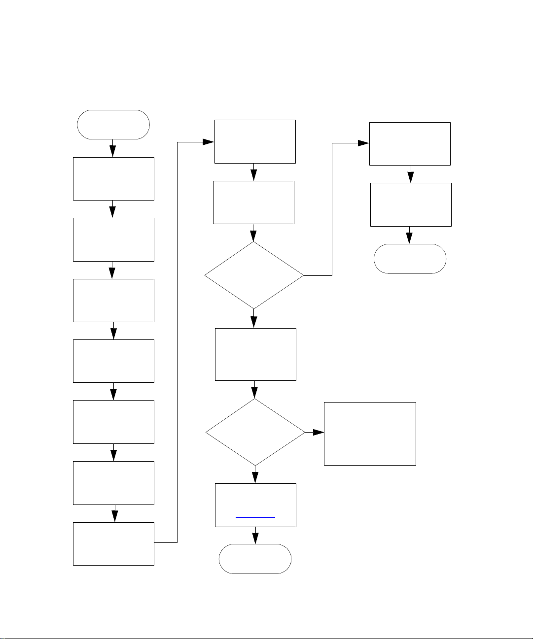
Summary of This Guide
The following figure summarizes the information contained in this Quick Start Guide. Use it
as a reference after reading the entire document.
Start
Power on the
2790
Configure the
2790
Degas Solvents
Configure the Plate
Type(s)
Load the Sample
Plates
Perform an
Automatic Run?
Yes
No
Set Flow Rate and
Composition
Select Direct
Function
Function Begins
Prime the
Solvent
Management
System
Prime the
Plunger-Seal-Wash
Pump
Prime the
Needle-Wash Pump
Refresh the Syringe
Create/Edit
Separations
Methods/Sample
Sets
Using
High-Throughput
Options?
No
Follow the
Procedures in
Section 4.1
Run Ends as
Programmed
Yes
Refer to Section 6.2,
Waters 2790
Separations Module
Operator’s Guide
Page 4

Conventions Used in This Guide
The
Waters 2790 Separations Module Quick Start Guide
uses the following conventions:
• Bold text indicates user input or action. For example, press
• When you are instructed to “press the X key,” press the indicated keypad key.
• When you are instructed to “press the X screen key,” press the key directly below
the key name displayed on the screen.
Enter
Notes, Attentions, and Cautions
This guide uses the following conventions for Notes , Attentions, and Cautions:
• Notes call out information that is important to the operator. For example:
Record your results before you proceed to the next step.
Note:
• Attentions provide information about preventing possible damage to the system or
equipment. For example:
To avoid damaging the detector flow cell, do not touch the flow cell
To avoid chemical or electrical hazards, always observe safe laboratory
To avoid electrical shock and possible injury, remove the power cord from
STOP
Attention:
window.
• Cautions provide information essential to the safety of the operator. For example:
Caution:
practices when you operate the system.
Caution:
the rear panel of the instrument before you perform the procedures in this section.
.
Page 5

1
Introduction
The
Waters 2790 Separations Module Quick Start Guide
features of the Waters
2790 Separations Module and describes how to make a run.
Who Should Use This Guide?
This guide is intended for both novice and experienced chromatographers who need to
operate the 2790 Separations Module.
What Is in This Guide?
The
Waters 2790 Separations Module Quick Start Guide
information to help you set up the 2790 and make a run.
For additional information, or if you want to learn how to modify any procedures in this
guide, refer to the
If you are using the 2790 as part of an Alliance
MassLynx software), ensure you become familiar with the procedures in:
• Waters Allian ce LC/MS Sy ste m Qu ick Sta rt Guid e
Waters 2790 Separations Module Operator’s Guide
HT LC/MS system (controlled by the
introduces you to the basic
contains basic procedural
.
• MassLynx NT Guide to Data Acquisition
• MassLynx NT User’s Guide
•
MassLynx NT BioLynx Guide
•
MassLynx NT OpenLynx Guide
(optional)
(optional)
Before You Begin
Ensure you have performed the following before you use the 2790:
• Your system is properly installed. Refer to the
Operator’s Guide
• You r separation methods and sam ple sets are created and stored. Refer to the
Waters 2790 Separations Module Operator’s Guide
Separation Methods and Sample Sets.
• Become familiar with the front panel and keypad operating procedures described in
the
Waters 2790 Separations Module Operator’s Guide
Display and Keypad.
, Chapter 2, Installing the 2790 Separations Module.
Waters 2790 Separations Module
, Chapter 5, Creating and Editing
, Section 3.1, Using the 2790
5
Page 6
If you are using the 2790 for high-throughput applications, refer to the
Separations Module Operator’s Guide,
Chapter 6, Making Automatic Runs and Setting Up
Waters 2790
for High-Throughput Operation.
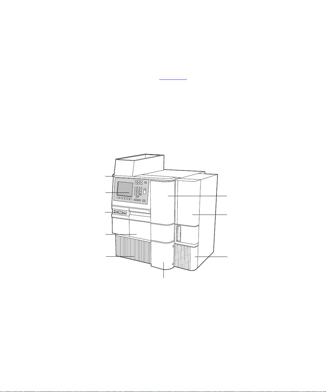
System Description
The Waters 2790 Separations Module (Figure 1-1) integrates a solvent management
system and a three-axis sample management system to provide high-throughput analysis
for HPLC, LC/MS, or flow injection-mass spectrometry applications.
When the 2790 is installed with a sample heater/cooler and a column heater, it is known
as the 2790XE. Refer to the
Waters 2790 Separations Module Operator’s Guide
Section B.3, 2790 Module Options, for information about the 2790 Separations Module
options.
Solvent Bottle Tray
Detector Drip Tray
,
Front Panel Display
and Key board
Floppy Disk
Drive
Sample Compartment
Access Door
Solvent Delivery Tra y
Access Door
Solvent Conditioning
Tray Access Door
Syringe Compartment
Door
Column Heater
Module
Column Selection Valve
(Optional) Door
TP01354
Figure 1-1 Waters 2790XE Separations Module (Front View)
The sample management system in the 2790 uses an XYZ needle assembly, up to four
sample plates of up to 384 wells each, for a total capacity of 1536 samples. The 2790 uses
a variety of plate types including several that are preconfigured (refer to the
Separations Module Operator’s Guide
, Table 3-6 and Table B-5).
Waters 2790
6 Introduction
Page 7

Operating Mode s
The 2790 Separations Module can operate in one of the following modes:
• Stand-alone HPLC system controller
• Component of an LC/MS system controlled b y MassLynx
As a stand-alone HPLC system controller, the 2790 manages both the solvent delivery
and sample management systems as well as controlling one or more detectors. The 2790
controls the sample plates using a rotating carrier. Optionally, the 2790 can also control a
three-column, six-column, or column regeneration selection valve.
An LC/MS system that includes the 2790 and the Waters ZMD mass spectrometer is
designated as a Waters Alliance HT LC/MS System. For further information on MassLynx
control of the 2790, refer to the
Waters Allianc e LC /MS System Quick St art Guid e
1.1 Powering On the 2790
To power on the 2790, move the power switch (located at the top of the left side panel) to
the I (ON) position. The startup diagnostics routine begins.
Startup Diagnostics
The startup diagnos tics routine performs tests on the:
™
software
.
• CPU board
• Memory (ROM and RAM)
• Keypad
•Display
• External communicat ion system
• Digital signal processor (DSP)
• Floppy disk drive
When initial startup diagnostics tests are complete, the front-panel screen displays the
tests results, as shown in Figure 1-2
Figure 1-2 Diagnostic Test Results Screen
.
Powering On the 2790 7
Page 8
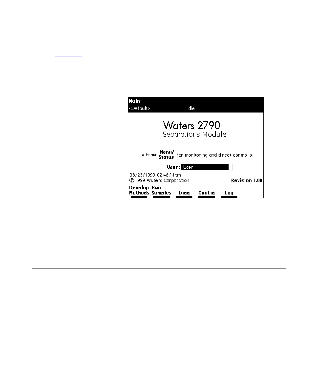
The Main Screen
If the initial tests of the startup diagnostics routine are successful, the Main screen
(Figure 1-3
continues, the status of each of diagnostic test appears in the banner area of the Main
screen. If the startup diagnostics routine fails, refer to the
Module Operator’s Guide,
routine finishes, the 2790 enters the Idle mode.
) appears in the front panel display. As the star t up diagno stics routine
Waters 2790 Separations
Section 8.5, Troubleshooting. When the startup diagnostics
Bann er Area
Data Area
Screen K ey Area
Figure 1-3 Main Screen
Some 2790 screens have additional screen keys that are not visible when you
Note:
display the screen f or the first time. Press the
keys.
1.2 Configuring the 2790
Before you can operate the 2790, you need to configure the 2790 operating parameters.
Press the
(Figure 1-4
8 Introduction
Config
screen key in the Main screen to display the Configuration screen
).
screen key to displa y additional screen
More
Page 9
500
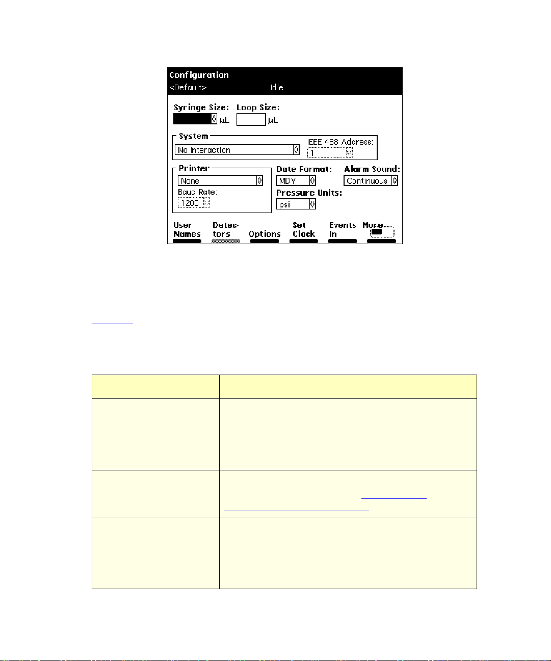
Figure 1-4 Configuration Screen
50
1.2.1 Setting Configuration Parameters
Ta ble 1-1 describes the parameters you can set for your system configuration.
Ta ble 1-1 Configuration Parameters
Parameter Description
Syringe Size and Loop
Size
System Specifies the operating mode and the IEEE-488 bus
Printer Specifies the type of printer and baud (data transfer)
Specifies the sizes of the syringe and sample loop.
These values are preset at the factory. Change these
values when you install a different-sized syringe and/or
sample loop (see the
Operator’s Guide,
address (when required). See Se ction 1.2.2,
Configuring the Operating Mode.
rate and flow control.
The baud rate is automatically set to 1200 if you
Note:
Waters 2790 Separations Module
Table 7-5).
set the 746 Integrator as the printer type.
Configuring the 2790 9
Page 10

Ta ble 1-1 Configuration Parameters (Continued)
Parameter Description
Date Format Specifi es MM/D D/ YYYY (f o r e xample, 0 3/ 28/1999 for
March 28, 1999) or DD.MM.YYYY (28.03.1999 for 28
March 1999).
Alarm Sound Specifies the type of alarm (continuous or single beep).
Pressure Units Specifies psi (pounds per square inch), kPa (kPascal),
or bar.
1.2.2 Confi guring the Operating Mode
On the Configuration screen, you configure the operating mode as follows.
No Interaction Mode
In this stand-alone mode, the 2790 is not connected to the IEEE- 488 interface bus , b ut
can control non-IEEE-488 devices in the HPLC system using the I/O connections on the
rear panel. Refer to the
Making Analog Signal Connections, for the procedure to make I/O connections.
Waters 2790 Separations Module Operator’s Guide,
Section 2.5.2,
To set the 2790 to No Interaction mode:
1. Select
operating modes.
2. Select
3. Press
System
No Interaction
Exit
System Controller Mode
In this stand-alone mode, the 2790 can control up to th ree de tector ch annels on t he
IEEE-488 bus. The channels can include up to two UV detector channels (a Waters 2487
Dual λ Detector and/or a Waters 486 Tunable Absorbance Detector) and one RI detector
channel (Waters 2410 or 410 Differential Refractometer).
Refer to the
Digital Signal Connections, for inf ormation on making IEEE-488 connections. You can also
control other HPLC components using the I/O connections. Refer to the
Separations Module Operator’s Guide,
for the information on making I/O connections.
10 Introduction
Waters 2790 Separations Module Operator’s Guide,
in the Configuration screen, then press
, then press
.
Section 2.5.2, Making Analog Signal Connections,
Enter
.
to display the list of
Enter
Section 2.5.3, M a k i ng
Waters 2790
Page 11

To set the 2790 to Sys tem Controll er mode:
1. Select
operating modes.
2. Select
3. P ress the
interface bus addresses) appears.
4. Press
For information on setting detector parameters in a separation method, see the
System
System Controller
a. Press
absorbance channels and one RI detector) may appear in the list.
b. Press the OK screen key to return to the Configuration screen.
Exit
2790 Separations Module Operator’s Guide,
in the Configuration screen, then press
, then press
Detectors
Scan
.
screen key. A li st of active devices (with their IEEE-488
to update the list of devices. Up to th ree dete ctors ( t wo
Section 5.2.6, Setting Detector Parameters.
Enter
.
Enter
to display the list of
Waters
Controlled by MassLynx Mode
In this remote control mode, the Micromass MassLynx NT s oftware (Version 3.3 or higher)
uses the IEEE-488 interface to control the 2790, and up to two detectors, including the:
• Micromass mass spectrometry (MS) detec tor
• Waters 996 PDA Detector
• Other Waters detectors, such as the 2487 Dual λ Absorbance Detector
To set the 2790 to Controlled by MassLynx mode:
1. Select
operating modes.
2. Select
is highlighted.
3. Press
4. Select an address that is unused by other chromatographic components connected
to the Micromass computer, then press
5. Press
System
Controlled by MassLynx
Enter
Exit
in the Configuration screen, then press
, then press
to display a list of addresses.
.
Enter
. The 2790 is ready to be controlled from the MassLynx computer.
. The IEEE-488 Address field
Enter
to display the list of
Enter
Configuring the 2790 11
Page 12

Operate Gradient by Event In Mode
In this mode, an external autosampler (a Waters 2700 Sample Manager, for example)
initiates the start of the chromatographic run and performs the inject function (instead of
can
the 2790). In t his mo de, t he 2790 has n o cont rol of IEEE -488 devices, but
non-IEEE devices using the I/O connections on the rear panel. Refer to the
Separations Module Operator’s Guide,
for information on I/O connections.
To set the 2790 to Operate Gradient b y Event In mode:
Section 2.5.2, Making Analog Signal Connections,
control
Waters 2790
1. Select
operating modes.
2. Select
3. Press
Events In conditions, refer to the
Guide
Conditions for Events In” discussion.
4. S et the Stop Flow field to the appropriate condition (
Low
On Low
5. S et the Hold 1 f ield to the appropr iate condition (
press
System
Operate Gradient by Event In
Events In
, Section 3.2.1, Setting Configuration Parameters, the “Specifying Signal
), then press
• Select
• Select
Flow I/O terminals of the 2790 is a high (more positive) TTL-level.
• Select
Flow I/O terminals of the 2790 is a low (more negative) TTL-lev el .
When you configure the 2790 with a Waters 2700 Sample Manager , select
Note:
.
Enter
• Select
Inject 1 terminals of the 2790 is a high (more positive) TTL-level to start a
chromatographic run and prevent an injection by the 2790.
in the Configuration screen, then press
, then press
to display the Events In dialog box. For information on defining
Enter
Waters 2790 Separations Module Operator’s
.
Enter
Ignore
On High
On Low
On High
if the Stop Flo w I/O t ermin als of t he 2790 are not used.
if the output signal from the external autosampler to the Stop
if the output signal from the external autosampler to the Stop
On High
.
if the output signal from the external autosampler to the Hold
to display the list of
Enter
.
Ignore, On High
or
On Low
, or
On
), then
• Select
Note:
On Low
6. S et the Logic field to Or, then press
12 Introduction
On Low
Inject 1 terminals of the 2790 is a low (more negative) TTL-level to start a
chromatographic run and prevent an injection by the 2790.
if the output signal from the external autosampler to the Hold
When configuring the 2790 with a Waters 2700 Sample Manager , select
.
.
Enter
Page 13
7. S et the Hold 2 field to
8. Press OK to save your selections and exit from the Events In dialog box.
Ignore
1.2.3 Specifying Report Options
, then press
Enter
.
The 2790 can generate a
operation, if a printer or integrator is connected.
Use Port A of the RS-232 connector to connect a cable from the 2790 to a serial
Note:
report
– a record of injections – during stand-alone or remote
printer or to a Waters 746 Data Module.
To define the information to be sent to a printer, integrator, and/or floppy disk:
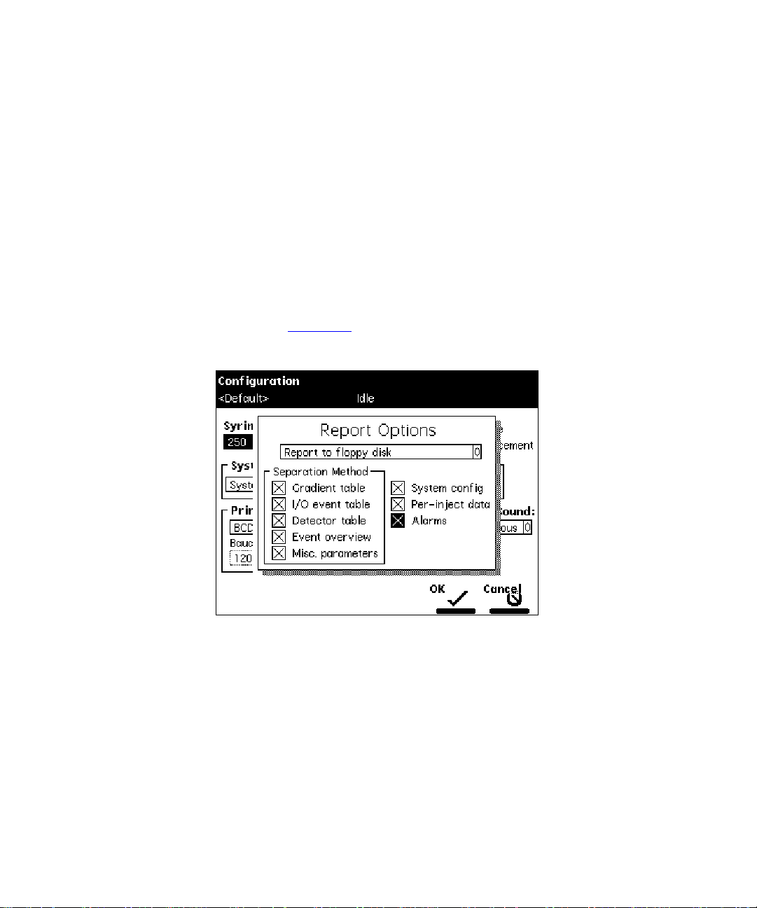
1. In the Configuration screen, press the
Options dialog box (Figure 1-5
).
Reports
screen key to display the Report
Figure 1-5 Report Options Dialog Box
2. From the drop-down list, select the destination for the report.
3. S elect an option from the Separation Method list, then press any numeric key to
enable or disable the option. An “X” in the check box indicates the option is
enabled. The options are:
•
Gradient ta ble
•
I/O eve n t table
•
Detector table
– Generates the gradient table
– Generates the I/O table
– Generates the detector table
Configuring the 2790 13
Page 14

•
Event overview
– Generates an overview of all merged tables
•
Misc. parameters
•
System config
•
Per-inject data
values for temperature and pressure, the time and date of each injection, and
the bar code number
•
Alarms
injection
4. Press the OK screen key to exit from the Report Options dialog box ( or press the
Cancel
your changes).
– Generates a list of the error conditions that occur during each
screen key to exit from the Repor t Options dialog box without saving
– Generates a list of all parameters not included in tables
– Generates a list of the instrument configuration parameters
– Generates a list of the minimum, maximum, and average
1.2.4 Specifying an Auto Shutdown
The Auto Shutd own f eatu re allows y ou t o set up t he 2790 to sh ut down auto m atic all y after
a specified period of inactivity. Inactivity is defined as:
• No keyboard use
• No injections performed
• No changes sent to the 2790 from a remotely connected MassLynx computer
• An error condition that suspends the operation of the 2790
You can use Auto Shutdown to:
• Minimize solvent flow when a run ends unattended
• Disable the vacuum degasser
• Disable temperature controls
• Turn off detector lamps
To enable an Auto Shutdown:
1. Press the
2. P ress the
(Figure 1-6
14 Introduction
Config
Auto Shutdown
screen key in the Main screen, then press the
).
screen key.
More
screen key. The Auto Shutdown dialog box appears
Page 15
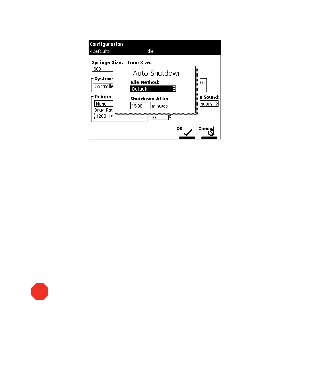
Figure 1-6 Auto Shutdown Dialog Box
3. I n the Idle Method field, select the separation method to be applied when the
2790 is shut down. Only the
applied during the shutdown period.
4. I n the Shutdown After field, enter a time period of inactivity after which you want
the 2790 to shut down (or press
5. P ress the OK screen key. The 2790 shuts down when there has been no activity
for the specified period.
6. Press
If you want to use Auto Shutdown to power off a 2487 or 486 detector lamp, specify
Note:
a Lamp Off event and a time of INIT in the I/O Events Timed Table screen (see the Waters
2790 Separations Module Operator’s Guide, Section 5.2.5, Setting I/O Parameter Values).
to return to the previous screen.
Exit
1.2.5 Configuring Plate Types
initial
conditions in the method you select are
to disable Auto Shutdown).
Clear
STOP
Attention:
Operator’ s Guide, Table B-5, before configuring plates for the 2790 Separations Module.
Read all the recommendations in the footnotes to Table B-5.
There are 15 possible plate types you can configure for use with the 2790, some of which
are preconfigured and not editable.
Waters recommends you consult the Waters 2790 Separations Module
Configuring the 2790 15
Page 16

When you select a preconfigured plate type, the parameter fields indicate the
Note:
measured dimensions for the specific plate, which are not editable (indicated by a dotted
line surrounding the field).
To customize a preconfigured plate type for the 2790:
STOP
1. In the Configuration screen, press the
Type Configuration dialog box (Figure 1-7
2. Select the plate type from t he Name dr op-down list. The remaining (noneditable)
fields fill with values corresponding to the selected plate type. To configure a
custom plate, see the “
3. I n the Sequential reference field, select the processing order (see Table 1-5
Ta ble 1-2
describes the fields in the Plate Type Configuration dialog box. See the
Configuring Custom Plates” discussion below.
2790 Separations Module Operator’s Guide
their dimensions) for use with the 2790.
Attention:
Using incorrect dimensions can cause needle damage.
Plate Types
).
, Tabl e B-5 for recommended plate types (and
screen key to display the Plate
Waters
).
16 Introduction
Page 17
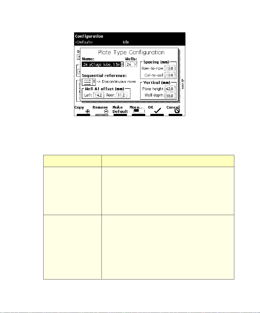
Figure 1-7 Plate Type Configuration Dialog Box
Ta ble 1-2 Plate Type Configuration Parameters
Field Description
Name Name of the plate type. Use up to 30 characters to identify a
plate type. Some of the 15 plate types are preconfigured.
To mov e from one plate type to the adjacent plate type in the
drop-down list, press the
Previous
or
screen key. The
Next
default plate type appears with an asterisk in the Name field
and the words “Default Plate Type” are displayed below the
Name field.
Wells Number of wells on the plate selected in the Name field. The
parameters for each plate type are:
Number of Wells Number of Rows
24
48
48R
96
384
4
6
8
8
16
Number of Columns
6
8
6
12
24
Configuring the 2790 17
Page 18

Ta ble 1-2 Plate Type Configuration Parameters (Continued)
Field Description
Sequential reference Direction and sequence of well injections for the selected
plate. See Table 1-5.
Well A1 offset (mm)
Left
The distance from the center of the A:1 well to the left outer
edge of the plate
Rear
The distance from the center of the A:1 well to the rear outer
edge of the plate. See Figure 1-9.
Spacing (mm)
Row-to-row
The distance from the centerline of the wells in one row to
the centerline of the wells in an adjacent row
Col-to-col
The distance from the centerline of the wells in one column
to the centerline of the wells in an adjacent column. See
Figure 1-9.
Vertical (mm)
Plate height
Well depth
1
Tot al plate height
The well depth (distance from the top of the plate to the
bottom of the well)
1
See the
plates recommended for use with the 2790.
Waters 2790 Separations Module Op erator’s Guide
, Table B-5, for dimensions of the
Configuring Custom Plates
You can use one of the preconfigured plate types to create a custom plate. Before
Note:
following the next procedure, select the preconfigured plate type that most resembles the
custom plate you want to create.
Required Materials
To make plate measurements, you need a ruler or straight-edge scaled in millimeters.
To configure a custom plate:
1. In the Plate T ype Configuration dialog box, press the
Custom Plate Name field (Figure 1-8
).
screen key to display the
Copy
18 Introduction
Page 19
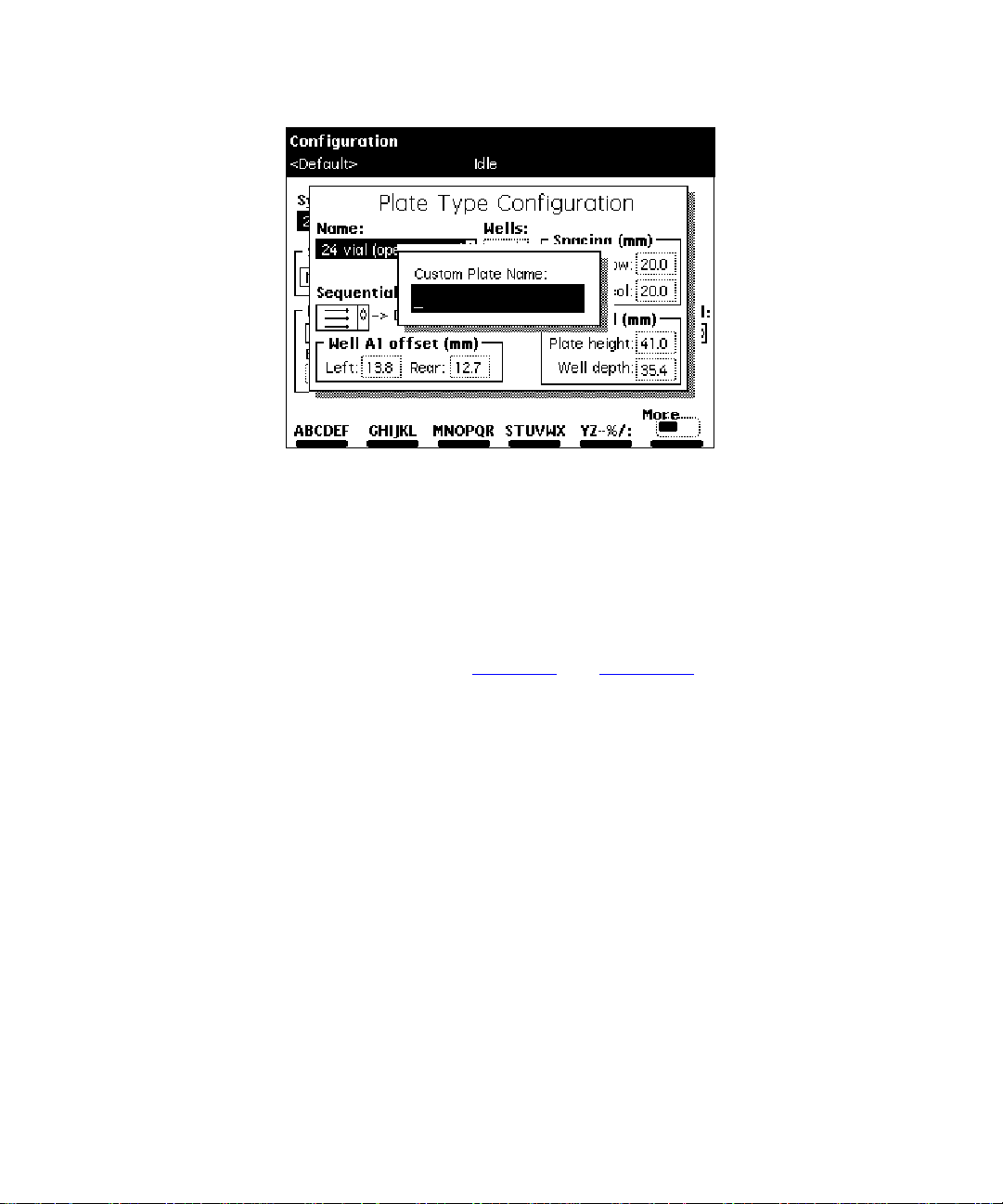
Figure 1-8 Custom Plate Name Field
2. E nter a custom plate nam e (see the
Operator’s Guide
, Section 3.1.2, Using the Keypad, the “Entering an
Alphanumeric String” discussion), then press
Waters 2790 Sepa rations Mod ule
. The Plate Type
Enter
Configuration parameter fields become editable (surrounded by a solid line).
3. Using a ruler or straight-edge scaled in millimeter s, measure the dimensions for
the custom plate as shown in Figure 1-9
and Figure 1-10, then enter each
parameter in the appropriate field in the Plate Type Configuration dialog box.
4. P ress the OK screen key to store the custom plate (or press the
Cancel
screen
key to discard the changes).
To delete the selected custom plate type, press the
Remove
screen key. The
Remove screen key is active only when a custom plate name is displayed in the
Custom Plate Name field. You c annot remove a preconfigured plate type.
To make the displayed plate type the default plate type, press the
Make De fa u l t
screen key. The factory-default plate type is 96 well, 300 µL. The words “Default
Plate Ty pe” are displayed below the default plate name in the Plate Type
Configuration dialog box.
Press the
Press the
Previous
Print
or
screen key to move from one plate type to another.
Next
screen key to print a copy of the plate configuration list to a
floppy disk or printer (if a printer is connected to your 2790).
Configuring the 2790 19
Page 20
The Needle Depth Offset parameter (
Note:
Figure 1-10
) is used to specify an offset from
the well bottom to accommodate sample vials or sedimentation. Enter the Needle Depth
Offset in the Sample screen when you are creating or editing a separation method (see
the Waters 2790 Separations Module Operator’s Guide, Section 5.1, Creating and Editing
Separation Methods).
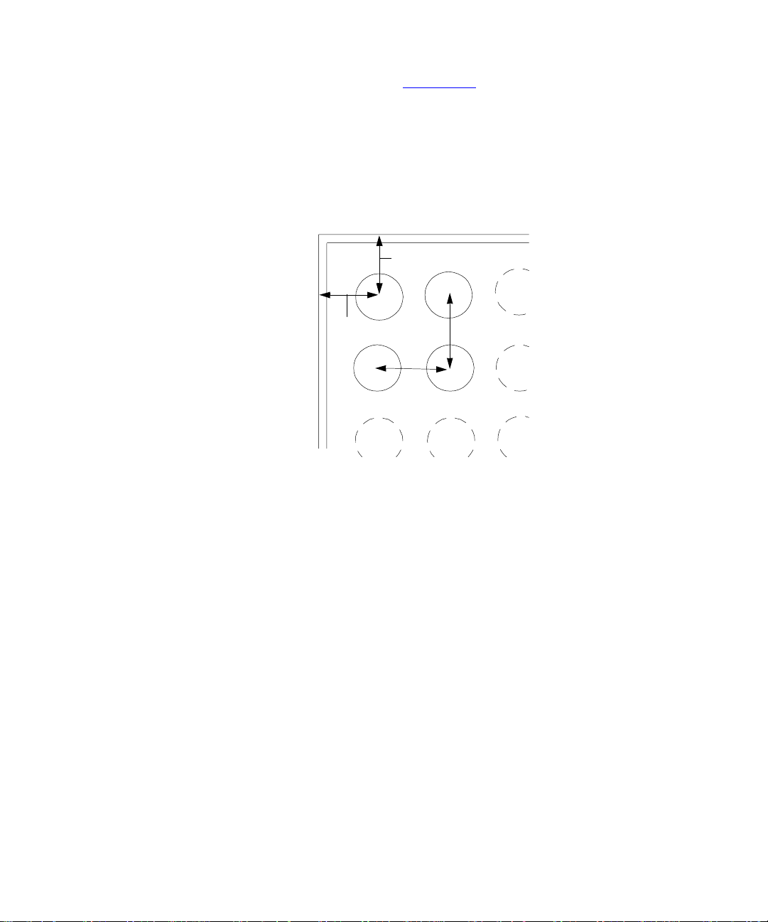
To p View Dimensions
Note:
Measure the A1 Left
and A1 Rear Ref erence points
(left and rear well of fsets) from
the outer edge of the plate.
1
A1 Rear
Reference
A
2
3
Outer Edge
of Plate
A1 Left
Reference
B
Column-to-Column
Spacing
Row-to-Row
Spacing
C
Figure 1-9 Plate Parameters (Top View)
20 Introduction
Page 21
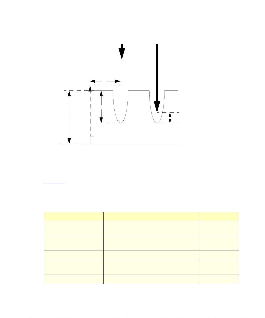
Side View Dimensions
Needle Up
A
Well Depth
Plate Height
*
The Needle Depth Offset parameter i s part of the separation method. See the
Module Operator’s Guide
, Section 5.1, Creating and Editing Separation Methods.
Needle Down
Needle Depth Offset
Waters 2790 Separations
Figure 1-10 Plate Parameters (Side View)
Ta ble 1-3
describes the preconfigured plate types for the 2790. The plate type names
appear as displayed in the Name field of the Plate Type Configuration dialog box.
*
Table 1-3 2790 Preconfigured Plate Types
Plate Type Name Description Part Number
24 uCfuge tube, 1.5 mL 24-well, 1.5 mL microcentrifuge tube
405000560
holder
24 vial (open access), 2 mL24-well, 2 mL vial, open access plate 200000114
48 vial holder, 2 mL 48-well, 2 mL vial holder 405000562
48 uCfuge tube, 0.5 mL 48-well, 0.5 mL microcentrifuge tube
405000561
holder
96 well w/700 uL insert 96-well with 700 µL glass insert plate 186000349
Configuring the 2790 21
Page 22

Table 1-3 2790 Preconfigured Plate Types (Continued)
Plate Type Name Description Part Nu mb er
96 well (tall), 350 uL 96-well tall, 350 µL polypropylene WAT058943
96 well (tall), 1 mL 96-well tall, 1 mL, polypropylene WAT058957
96 well (tall), 2 mL 96-well tall, 2 mL, polypropylene WAT058958
96 well, 300 uL
(Default)
96-well, 300 µL, polypropylene or
polystyrene
Non-Waters
384 well, 80 uL 384 well, 80 µL, polystyrene Non-Waters
1
Check the dimensions of all non-Waters plates . For more information on these and other
2790-compatible plates, see the
Waters 2790 Separation s Mo dule Operator’s Guide
1.3 Preparing the Solvent Management System
For optimal performance of t he 2790, y ou need to prepare the solvent and the sample
management systems for operation. Preparing the solvent management system inv olves:
1
*
, Table B-5.
1. Preparing solvent reservoirs (Section 1.3.1
2. Degas sing solvents (Section 1.3.2
)
3. P rim ing the plunger-seal-wash pump (Section 1.3.3
4. P rim ing the s olvent management system (Section 1.3.4
)
)
)
For information on preparing the sample management system, see Section 1.4,
the Sample Management System.
To maintain the efficiency of the solvent management system, and to obtain
Note:
accurate, reproducible chromatograms, use only HPLC-grade solvents.
Preparing
22 Introduction
Page 23

Caution:
Material Safety Data Sheets for the solvents you use.
Observe safe laboratory practices when you handle solvents. Refer to the
1.3.1 Preparing Solvent Reservoirs
Choose solvent reservoirs that provide a snug fit for the reservoir caps supplied in the
startup kit. Waters recommends 1-L reservoirs.
To maintain adequate s olvent head pressure and ensure proper solvent
To prevent solvent overflow, Waters recommends that pressurized solvent
Section 2.4, Making Fluidic Connections.
STOP
STOP
Attention:
delivery, position the solvent reservoirs above the level of the solvent management
system, at least 20 inches (50.8 cm) above the laboratory bench.
Attention:
reservoir bottles not be used. Pressures above 5 psi can cause solvent to be forced
through the internal components of the gradient proportioning valve (GPV), possibly
causing a spillover into the solvent waste reservoir or an ad verse m ix tur e w it h other
solvents in the GPV.
Install the solvent and vent lines as described in the
Operator’s Guide,
1.3.2 Degassing S olvents
Do not run the degasser in Continuous mode unless solvent is flowing through
For optimum efficiency when running the degasser in Normal mode, ensure that all
Only three analytical solvents are degassed using the 2790 in-line degasser. The
STOP
Attention:
the supply tubes. Without solvent flow, e xc ess solvent vapor may condense in the
degasser vacuum chamber walls, which could lead you to suspect a vacuum chamber
leak.
Note:
degasser solvent lines are filled with solvent.
Note:
sample management system uses the fourth (D) chamber of the in-line degasser to degas
the purge solvent. To degas a fourth analytical solvent, use an external solvent degasser,
such as the Waters Two-Channel In-line Vacuum Degas ser (P/N WAT079700) or the
Waters Four-Channel In-line Vacuum Degasser (P/N WAT079800).
Waters 2790 Separations Module
To control the in-line vacuum degasser :
1. Press
2. P ress the
Menu/Status
(Figure 1-11
Next Page
).
. The Status screen is displayed.
screen key (if necessary) to display the Degasser fields
Preparing the Solvent Management System 23
Page 24

3. S elect the
degasser modes:
Degasser
mode field, then press
to display the following list of
Enter
•
Normal
•
Continuous
•
Disable
Degasser Modes
4. S elect the desired operating mode, then press
The Vac pump field displays the current status of the degasser vacuum pump.
The Pressure field displays the current vacuum level in psi, bar, or kPa.
– The degasser cycles on and off on a pressure-regulated cycle.
– The degasser is always on.
– The degasser is always off.
psia
Figure 1-11 Degasser Modes on Status Screen
.
Enter
1.3.3 Priming the Plunger-Seal-Wash Pump
The plunger-seal-wash solvent lubricates the solvent management system plunger and
flushes away solvent or precipitated salts forced past the plunger seal from the
high-pressure side of the solvent piston chamber (see the
Module Operator’s Guide
Required Materials
You need the following materials:
• Tubing adapter (startup kit)
• 30-mL syringe (startup kit)
• Seal-wash solution
24 Introduction
, Figure 7-2).
Waters 2790 Separations
Page 25

Ensure the plunger-seal-wash supply line (labeled “Seal Wash In”) is in the
Note:
plunger-seal-wash solvent bottle and that the plunger-seal-wash waste line is in an
appropriate waste container.
To prime the plunger-seal-wash pump:
1. Disconnect the inlet filter from the plunger-seal-wash inlet tube.
2. Connec t the tubing adapter to the syringe.
3. Fill the syringe with plunger-seal-wash solution, then connect the syringe
assembly to the plunger-seal-wash inlet tube.
4. I n the Main screen, press the
screen key. The Prime Seal Wash dialog box appears (Figure 1-12
When the Prime Seal Wash procedure is not running, the dialog box reads
Note:
screen key, then press the
Diag
“Idle.”
Figure 1-12 Prime Seal Wash Dialog Box
Prime SealWsh
).
5. Press the
on the syringe plunger to push plunger-seal-wash solvent through the system.
6. When the plunger-seal-wash solvent is flowing out of the plunger-seal-wash
waste tube, press the
If you do not press
minutes.
screen key to begin the seal-wash priming procedure, then push
Start
screen key.
Halt
, the seal-wash pump priming procedure stops after 15
Halt
Preparing the Solvent Management System 25
Page 26

7. Press the
to return to the Main screen.
Note:
wash solvent, depending on your application.
8. Rem ove the syringe and adapter, reconnect the filter, and place the
plunger-seal-wash inlet tube into the purge/plunger-seal-wash solvent reservoir.
Close
You can use the same solvent for both the purge solvent and the plunger seal
screen key to return to the Diagnostics screen, then press
Exit
For more information on performing diagnostics procedures, see the
Separations Module Operator’s Guide
, Chapter 8, Diagnostics and Troubleshooting.
Waters 2790
1.3.4 Priming the Solvent Management System
Prime the solvent management system using the:
• Dry prime direct function when the solvent lines are dry
(see Section 2.2.1,
• Wet prime direct function when you want to switch from one solvent to another
(see Section 2.2.2,
Dry P r im ing).
Wet Priming).
1.4 Preparing the Sample Management System
Prepare the sample management system for operation after you have prepared the
solvent management system (Section 1.3,
Preparing the sample management system involves:
1. Priming the needle-wash pump (Section 1.4.1
2. Ref reshing the syr inge (Section 1.4.2
3. Loading the sample plates (Section 1.4.3
Before using the sample management system for the first time, become familiar with the
procedures in the
Performing Direct Functions, and Section 4.3, Monitoring System Status.
Waters 2790 Separations Module Operator’s Guide,
Preparing the Solvent Management System).
)
)
)
Section 4.2,
1.4.1 Priming the Needle-Wash Pump
The needle-wash pump flushes the needle in the sample management system with wash
solvent, prev enting carryover of sample between injections. The needle wash also extends
the life of the inject port seat by removing buffered mobile phase and sample from the
needle.
26 Introduction
Page 27

Prime the needle-wash pump when one or both of the following occurs:
• There is a lack of flow in the needle-wash system.
• You are changing the wash solvent.
Selecting the Needle-Wash and Purge Solvents
Use a needle-wash solvent based on the sample and mobile phase chemistries, making
sure all solutions/buffers are miscible and soluble. Table 1-4
purge solvents recommended for use with certain mobile phase conditions. High sample
concentrations may require other needle wash solvents.
Ta ble 1-4 Suggested Needle-Wash and Purge Solvents
lists some needle-wash and
Chromatographic
Condition
Buffered aqueous,
reversed-phase
Wash Solvent Purge Solvent
50 to 100% MeOH or
ACN
90% H2O, 10% MeOH or
ACN to 50% H
MeOH or ACN
Nonaqueous,
100% MeOH Mobile phase
reversed-phase
Normal phase Mobile phase Mobile phase
GPC Mobile phase M obi le phase
Ion exchange 90% H2O, 10% MeOH H2O
Required Materials
You need the following materials:
• 30-mL syringe (startup kit)
• Tubing adapter (startup kit)
• Wash solvent
O, 50%
2
Be sure the needle-wash fluidic lines and reservoirs are installed properly (see the
Note:
Waters 2790 Separations Module Operator’s Guide, Section 2.4.5, Installing the Wash
Reservoirs).
Preparing the Sample Management System 27
Page 28

To prim e the needle-wash pump:
1. Remove the inlet filter from the needle-wash inlet tube.
2. Connec t the syringe adapter to the 30-mL syringe.
3. Fill the syringe with wash solvent and connect it to the wash-solvent inlet tube.
4. P ress the
5. P ress the
box appears (Figure 1-13
screen key in the Main screen. The Diagnostics screen appears.
Diag
Prime NdlWash
screen key. The Pr ime Needle Wash Solvent dialog
).
Figure 1-13 Prime Needle Wash Solvent Dialog Box
6. P ress the
screen key to begin the needle wash, then press lightly on the
Start
syringe plunger to push need le-wash solvent t hrough the needle-wash system. If
solvent does not flow out of the needle-wash-waste tubing within 30 seconds,
press
a second time.
Start
If solvent still does not flow out of the waste line, check for leaks in the tubing or
sample management compartment.
7. When needle-wash solvent flows out of the needle-wash waste tube, press the
Halt
If you do not press
seconds.
8. Press the
to return to the Main screen.
9. Rem ove the syringe and adapter, reconnect the filter, and place the solvent line
back in the needle-wash solvent reservoir.
28 Introduction
screen key.
Close
, the needle-wash prime procedure stops after 30
Halt
screen key to return to the Diagnostics screen, then press
Exit
Page 29

For more information on performing diagnostics procedures, see the
Separations Module Operator’s Guide
1.4.2 Refreshing the Syringe
Refresh the syringe whenever you do any of the following:
• Prime the solvent management system
• Change solvents
• See bubbles in the syringe
• Star t using the 2790 at the beginning of each day
Waters 2790
, Chapter 8, Diagnostics and Troubleshooting.
STOP
Attention:
To prevent degradation to the syringe and valves, avoid the use of salt buffers
in the purge solvent. Use a low concentration (0% to 50%) organic-aqueous solvent that is
similar to the mobile phase, initial gradient conditions, or sample diluent (see
When you purge the syringe for the first time or when you change the purge solvent,
Note:
set the number of syringe strokes to 80 and the replacement volume to
600
Table 1-4
µ
L. This
).
volume fills the entire degasser chamber and the associated inlet tubing (with the standard
500-µL syringe installed).
To refresh the syring e:
1. Press the
Menu/Status
key. The Status screen appea rs (Figure 1-14
).
psia
Figure 1-14 Status Screen
Preparing the Sample Management System 29
Page 30

2. Turn on the degasser by selecting either
Degasser drop-down list (see the
Guide
, Section 4.3, Monitoring System Status).
Waters 2790 Separations Module Operator’s
Normal
or
Continuous
mode in the
3. P ress the
(Table 2-1
4. S elect the
dialog box appears (Figure1-15
Direct Function
).
Refresh Syringe
Figure 1-15 Refresh Syringe Dialog Box
screen key. A list of direct functions appears
option, then press
).
. The Refresh Syringe
Enter
5. E nter the number of s yringe strokes and the replacement volume of degassed
solvent in the appropriate field. Start with
replacement volume. To pr ime a new or dry instrument, or when you change the
purge solvent, refer to the previous Note.
6. P ress the
screen key. The Refresh Syringe cycle begins.
OK
1.4.3 Loading the Sam ple Pla tes
Attention:
STOP
30 Introduction
the needle or XYZ mechanism.
The 2790 plate carrier holds up to four rectangular plates that you load through the front
panel compart men t door (F igure 1-16
located in the left rear corner and the front edge of the plate is behind the guide button on
the front edge of the carrier (Figure 1-16
Using vial caps smaller than 8.8 mm in diameter (outer diameter) can damage
syringe strokes and
12
). Load each plate so that position A:1 (or 1) is
).
600
µL
Page 31

The plate carrier guides hold each plate loosely in place until the plate is moved to the
Inject position. At that time, a plate positioning spring pushes the plate toward the A:1 (left
rear) corner and holds it in position.
STOP
To move the plate carrier from one position to the next, press the
Next
press the color-coded plate number screen key in the Door Is Open dialog box
(Figure 1-17
Attention:
).
The 2790 cannot draw or inject samples when the sample compartment door
is open.
Guide
Button
Plate Carrier
Compartment Door
screen key or the
Sample
(Open)
TP01631
TP01631
Figure 1-16 Positioning the Sample Plate
If you power on the 2790 with the sample compar tment door open, close the door,
Note:
then reopen it to replace a sample plate on the carrier.
To load the plates onto the plate carrier:
1. Open the 2790 sample compartment door. The Door Is Open dialog box appears
(Figure 1-17
).
Preparing the Sample Management System 31
Page 32

2. P ress the
screen key or select the desired plate number to position the
Next
plate carrier for loading the appropriate plate.
Carrier plate positions are numbered 1 through 4, with individual color
identification as follows:
Position 1 Blue
Position 2 Yellow
Position 3 Red
Position 4 Green
3. Load the plate into the sample compartment with well A:1 (or position 1) at the
left rear position as the plate is loaded into the carrier.
4. Repeat s teps 2 and 3 until all plates are loaded.
5. Close t he s ample compartment door. The Door Is Open dialog box closes and
you return to the previous screen.
The 2790 uses
to locate samples on the plates. For example, sample positions on a:
• 24-vial plate are designated A-D:1-6
• 48-well plate are designated A-F:1-8 or A-H:1-6
32 Introduction
Figure 1-17 Door Is Open Dialog Box
plate logic
(based on letter labels for rows and number labels f or columns)
Page 33

• 96-well plate are des igna ted A-H:1-12
• 384-well plate are designated A-P:1-24
The 2790 also uses a simple numerical well location scheme, where well number 1 is
located at Row 1, Column 1. You can customize the processing order (also known as the
sequential reference
Ta ble 1-5
.
) in the Plate Type Configuration dialog box. See Figure 1-7 and
Position A:1 (or 1) is always located at the left rear of a plate as it is loaded into the carrier.
(Figure 1-16
).
Ta ble 1-5 Sequential Well Location Schemes for Sample Processing Order
Processing Order Icon Function Example (48 Wells)
Left to right, top to
bottom
Increasing columns,
then increasing
rows. Also called
Discontinuous
(horizontal).
Top to bottom, left to
right
Increasing rows,
then increasing
columns. A lso called
Discontinuous
(vertical).
Horizontal
serpentine
Left to right until end
of row, then right to
left starting at next
row. Also called
Continuous
(horizontal).
Vertical ser pentine Top to bottom until
end of column, then
bottom to top
starting at the next
column. Also called
Continuous
(vertical).
12345678
12345678
A
9 10111213141516
B
17 18 19 20 21 22 23 24
C
25 26 27 28 29 30 31 32
D
33 34 35 36 37 38 39 40
E
41 42 43 44 45 46 47 48
F
12345678
1 7 13 19 25 31 37 43
A
2 8 14 20 26 32 38 44
B
3 9 15 21 27 33 39 45
C
4 10162228344046
D
5 11172329354147
E
6 12182430364248
F
12345678
A
12345678
B
16 15 14 13 12 11 10 9
C
17 18 19 20 21 22 23 24
D
32 31 30 29 28 27 26 25
E
33 34 35 36 37 38 39 40
48 47 46 45 44 43 42 41
F
12345678
1 12132425363748
A
2 11142326353847
B
3 10152227343946
C
4 9 16 21 28 33 40 45
D
5 8 17 20 29 32 41 44
E
6 7 18 19 30 31 42 43
F
Preparing the Sample Management System 33
Page 34

For more information on configur ing sam ple plates, see Section 1.2.5, Configuring Plate
Type s . For more information on selecting individual well locations or grouping wells, see
Section 2.2.8,
Selectin g Wells for Making Injectio ns .
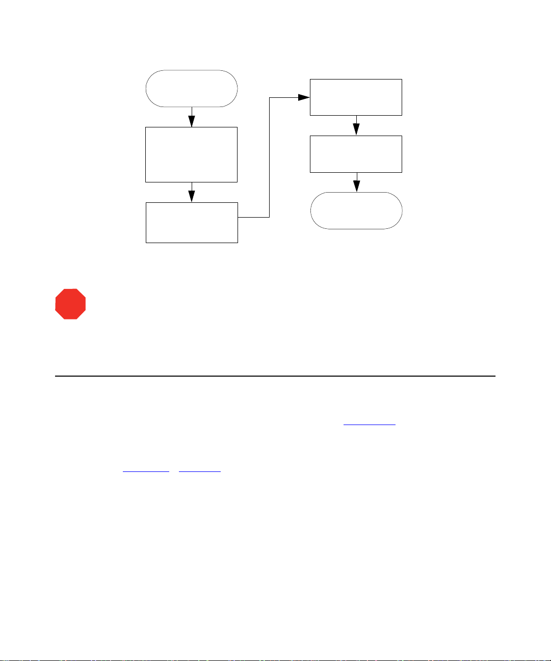
1.5 Preparing the 2790 for Operation
This section outlines in flowchart form the steps to prepare the 2790 for oper ation starting
from three different conditions:
• New or dry
• Powered off or left idle with no solvent flow
• Changing solvents (for example, from a buffered to an organic solvent)
The priming, purging, equilibrating, and other procedures outlined here are described in
detail in Section 2.1,
Accessing Direct Functions.
Figure 1-18
outlines how to prepare a new or dry 2790 for operation.
34 Introduction
Page 35

Start
Fill the Solvent
Reservoirs with Fresh
Solv ent Filtered and
Degasse d b y Vacuu m
Filtration
(Section 1.3.2
a
)
Prime the
Plunger-Seal-Wash
Pump (Section 1.3.3
If Running a Gradient
(for Example, A:B), Set
the A an d B
Composition Fields in
the Status Screen to
50%
)
, Then Wet P rime
for 2 min. at
5.00
mL/min.
(Section 2.2.2
)
Set the Degasser to
Continuous (See
“
Equilibrating Solvents
in the Vacuum
Degasser” in
Section 2.2.2
)
Perform a Dry Prime to
Fill Each Solvent Line
and
Degasser Chamber
(Section 2.2.1
)
Equilibrate the Solvent
in the De gasser
Chamber for 5 min at
a Flow Rate of
mL/min
“
Equilibrating Solvents
a
(See
0.000
in the Vacuum
Degasser” in
Section 2.2.2
b
)
Perform a Wet Prime
(for One of the
5.00
10
mL/min
min at
)
Solvents) for
(Section 2.2.2
Prime the Needle -
Wash Pump
(Section 1.4.1
)
Repeat th e Wet Prim e
at the Same Rate and
Time for Each of the
Remaining Sol vents
Set the Degasser to
Normal
(See “
Equilibrating
Solvents in the
Vacuum Degasser” in
Section 2.2.2
)
Equilibrate for a
Minimum of 10 Col umn
Volumes
(Section 2.2.5
)
Refr esh the S yringe f or
a Minimu m of
80
Cycle s and a
Replacement Volume
600
of
(Section 1.4.2
µL
)
System Is Ready
a. To maximize degasser efficiency, Wate rs recommends tha t all four solvent reservoirs be filled (the
fou rth chamber i s used for degassing the purge solvent). If you choose wat er as an “unused”
solvent, change the water weekly to pre vent bacterial contamination.
b. Except for the bri ef period of time required to equilibrate solvents in the degasser, do no t run the
degasser without solvent flow. Refer to the
Waters 2790 Separ ations Module Operator’s Guide
,
Section 1.2.2, the “In-Line Vacuum Degasser” discussion.
Figure 1-18 Preparing a New or Dry 2790 for Operation
Preparing the 2790 for Operation 35
Page 36

Figure 1-19 outlines how t o prepare fo r operation a 2790 t hat is po wer ed off or i s idle with
no solvent flow.
Start
Set the Degasser to
Continuous
“
Equilibrating
(See
Solv ents in the
Va cu um De ga sse r”
Section 2.2.2
Perform a Wet Prime
(for One of the
Solvents) for
7.500
mL/min
(Section 2.2.2
Repeat the Wet Prime
at the Same R at e an d
Time f or Each Solv ent
2
in
)
min at
)
Equilibrate* the
Solvent in the
Degasser Chamber
for 5 min. at a Flow
0.000
Rate of
(See
Solvents in the
V acu um Dega ss er”
Section 2.2.2
If You Are Runn ing a
Gradient (for Example,
A:B), Set the A and B
Composition Fields in
the Status Screen to
50%
, Then Wet Prime
for 3 min at
mL/min (Section 2.2.2
mL/min
“
Equilibrating
5.00
in
)
Set the Degasser to
Normal
“
Equilibrating Solvents
in the Vacuum
Equilibrate for a
Minimum o f 10 Col umn
(Section 2.2.5
Refresh the Syringe for
a Minimu m of
)
Replac ement Volume
(Section 1.4.2
System Is Ready
(See
Degasser”
Section 2.2.2
Cycle s and a
of
volumes
600
µL
in
)
)
12
)
* Except for the brief period of time re quired to equilibrate solvents in the degasser, do not run the degasser
without solvent flow. Refer to the
“In-L ine Vacuum Degasser” discussion, and Section 1.3.2
Waters 2790 Separations Module Operator’s Guide
in this guide for more details.
, Section 1.2.2, the
Figure 1-19 Preparing an Idle or Powered-Off 2790 for Operation
36 Introduction
Page 37

Figure 1-20 outlines how to change from a buffered solvent to an organic solvent.
Start
Remove the S olvent
Line from the
Reservoir with the
Buffer ed Solve nt
Remove the Solvent
Line from the
HPLC-Grade Water
STOP
Using a Flow Rate of
2.000
mL/min, Perform
a Wet Prime Until Air
Begins to Enter the Line
Place the Previously
Removed Solvent Line
Prime for 10 min. at
Attention:
(Section 2.2.2
into Filter ed
HPLC-Grade Water
and Perform a Wet
mL/min.
(Section 2.2.2
To avoid precipitating salts in the 2790, use an intermediate solvent
)
5
)
such as water when you change from buffers to high-organic-content solvents.
Fill a Clean Solvent
Reservoir with the
Organi c Solvent and
Plac e th e S olv e nt L in e
in the Reservoir
Perform the Steps in
Figure 1-19
For more information, refer to the Waters 2790 Separations Module Operator’s
Guide, Section D.3, Solvent Miscibility.
* Except for the brief period of time required to equilibrate solvents in the degass er, do not run the degasser
in Continuous mode without solvent flow. Refer to the
Section 1.2.2, the “In-Line Vacuum Degasser ” discussion, an d Section 1.3.2
Wa ters 2790 Separ ations Module Operator’s Guide
in this guide for more details.
Figure 1-20 Changing from a Buffered Solvent to an Organic Solvent
,
Preparing the 2790 for Operation 37
Page 38

2
Performing Direct Functions
You can perform many functions through the front panel controls when the 2790 is in
System Controller mode or No Interaction mode (see the
Module Operator’s Guide,
Section 3.2.3, Configuring the Operating Mode).
Waters 2790 Separations
You perform
functions be performed automatically as par t of a separation method (see the
2790 Separations Module Operator’s Guide
Separation Methods).
Direct functions are:
• Dry pr iming (Section 2.2.1
• Wet priming (Section 2.2.2
• Refreshing the syringe (Section 1.4.2
• Purging the 410 or 2410 (if RI detector is installed) (Section 2 .2.3
• Washing the needle (Section 2.2.4
• Equilibrating the system (Section 2.2.5
• Conditioning the column (Section 2.2.6
• Injecting samples (Section 2.2.7
Figure 2-1
functions.
To perform direct functions when the 2790 is controlled by the MassLynx software,
Note:
you need to exit MassLynx control and configure the 2790 for No Interaction mode (see
the Waters 2790 Separations Module Operator’s Guide, Section3.2.3, Configuring the
Operating Mode).
dire ct fun c ti ons
outlines the procedure for using the 2790 front panel to perform direct
as needed during operation. You can also specify these
Waters
, Section 5.1, Creating and Editing
)
)
)
)
)
)
)
)
For information on configuri ng the MassLynx software, see the
Data Acquisition
38 Performing Direct Functions
or the
Waters Alliance LC/ M S S y ste m Qu ick St art Gu ide
MassLynx NT Guide to
.
Page 39
Menu/
Press
Status
Key
Select Separat ion
Method, or Enter
Parameter Values in
the Status Screen
Direct
Press
Function
Select the Direct
Function to Perform
Enter the Function
Parameters
The Function
Begins to Run
Figure 2-1 Steps to Setting Up a Direct Function Control Run
If you make any changes to an existing separation method in the Status
STOP
Attention:
screen, the Method field changes to <direct>, the separation method name in the banner
area is enclosed within brackets (< >), and the current isocratic conditions (with no timed
events) are applied.
2.1 Accessing Direct Functions
To access direct functions:
1. Press
Menu/Status
2. S elect an existing separation method or enter parameter values.
3. P ress the
(Figure 2-2
Direct Function
). Table 2-1 describes the direct functions.
to display the Status screen (Figure 1-14
screen key. A list of direct functions appears
).
Accessing Direct Functions 39
Page 40

Figure 2-2 Direct Functions List
4. S elect a function, then press
described in the following sections. See the
Operator’s Guide
, Section 3.1.2, Using the Keypad, the “Entering and Editing
. Follow the instructions for each function, as
Enter
Waters 2790 Separations Module
Values” discussion, if necessary.
Ta ble 2-1 Direct Functions
Direct Fu nct i on Description Reference
Dry Prime Opens the fluidic path (from the selected
solvent reservoir to the prime/vent valve)
Section 2.2.1, Dry
Priming
to replace air with solvent, t hen performs
a prime.
We t P rim e Replaces solvent in the fluidic path from
the reservoirs through the Prime port of
Section 2.2.2, Wet
Priming
the inject valve to waste. Use to change
the solvent(s) in the system.
Refresh Syringe Refills the syringe with fresh, degassed,
purge solvent.
Section 1.4.2,
Refreshing the
Syringe
40 Performing Direct Functions
Page 41

Table 2-1 Direct Functions (Continued)
Direct Fu nct i on Description Reference
Purge 410/2410
(if applicable)
Wash Needle Washes both the outside and inside of
Equilibrate Selects a column position (if applicable)
Condition Column Selects a column position (if applicable)
Inject Samples Injects a sample one or more times from
Purges the Waters 410 or 2410 RI
detector reference cell.
the needle using wash solvent.
and specifies the system equilibration
time.
and delivers mobile phase using the
gradient table specified in the current
separation method.
the specified well(s) using the selected
method.
2.2 Performing Direct Functions
Section 2.2.3, Purging
the 410 or 2410
Reference Cell
Section 2.2.4,
Washing the Needle
Section 2.2.5,
Equilibrat ing th e
System
Section 2.2.6,
Conditioning the
Column
Section 2.2.7,
Injecting Samples
2.2.1 Dry Priming
Use the dry prime option to prime the system when the fluidic path in the solvent
management system is filled with air.
Required Materials
You need a 30-mL syringe (startup kit).
To perform a dry pri me:
1. Set up the reservoirs as described in Section 1.3.1,
2. I nsert the solvent tubing into the appropriate reservoir(s). Be sure the detector
waste line and the sample loop waste line drain into an appropriate container.
3. Gently shake the filters in the reservoirs to remove any bubbles that may be
trapped.
Preparing Solvent Reservoirs.
Performing Direct Functions 41
Page 42

4. A ttach an empty syringe to the prime/vent valve, as shown in Figure 2-3, then
open the valve by turning it counterclockwise 1/2-turn.
5. Press
Menu/Status
The syringe does not lock onto the prime/vent valve; hold it in place while you
Note:
pull on the plunger.
to display the Status screen (Figure 1-14
TP1359A
TP01359A
Figure 2-3 Prime/Vent Valve with Syringe
).
6. P ress the
(Figure 2-2
7. Select
(Figure 2-4
42 Performing Direct Functions
Direct Function
).
Dry Prime
).
screen key. The Direct Functions list appears
, then press
. The Dry Prime dialog box appears
Enter
Page 43
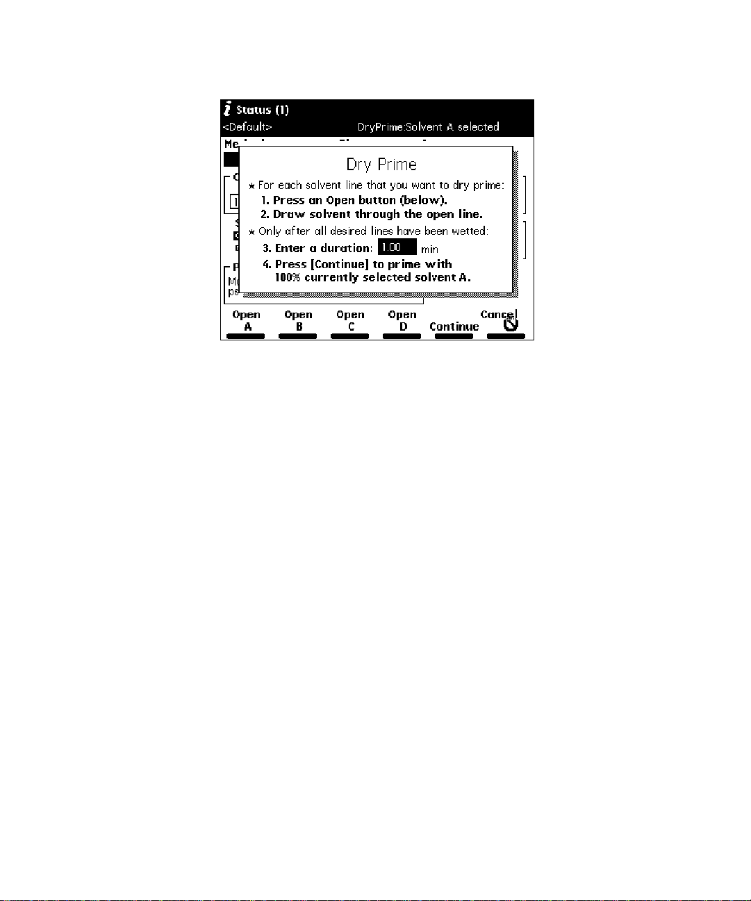
Figure 2-4 Dry Prime Dialog Box
8. P ress the s creen key corresponding to the solvent line you want to prime.
9. Withdraw the syringe plunger to pull solvent through the t ubi ng. You may need t o
exert force to pull the air and solvent through the system. Continue until you pull
all the air through the solvent line into the syringe.
10. Repeat steps 7 to 9 for each solvent line you want to prime, then close the
prime/vent valve.
11. Press a screen key corresponding to the solvent line with which you want to
prime the system.
Waters recommends that you prime using the solvent with the lowest
Note:
viscosity to help purge air from the lines, especially if the in-line vacuum degasser is
installed.
12. Enter the length of time (in minutes) to prime the solvent management system in
the Enter a duration field. Start with a value of 5 minutes. Press the
screen key.
The solvent management system starts the prim ing function. At the end of the
priming period, the solvent management system turns off and the 2790 enters
the Idle mode.
13. Perform a wet prime, as described below.
Continue
Performing Direct Functions 43
Page 44

2.2.2 Wet Priming
STOP
STOP
Attention:
To avoid damaging the plunger seals, perform a wet prime only when there is
solvent in the solvent management system fluidic path.
Perform a wet prime:
• When you want to change reservoirs or solvents
• If the 2790 has been idle for some time
• If you have just completed a dry prim e
The wet prime replaces solvent in the path from the reservoirs through the Prime position
of the inject valve to waste. If the solvent lines are dry, perform the dry prime procedure
before continuing (see Section 2.2.1,
Attention:
To avoid having salts precipitate in the 2790, use an intermediate solvent such
Dry Priming).
as water when you change from buffers to high-organic-content solvents. Refer to the
Waters 2790 Separations Module Operator’s Guide, Section D.3, Solvent Miscibility, for
information on solvent miscibility.
To perform a wet prime:
1. Press
2. I n the Composition field, enter
Menu/Status
priming.
to display the Status screen (Figure 1-14).
% for the solvent you want to use for wet
100
Waters recommends that you star t the wet prime using the solvent with the
Note:
lowest viscosity to help purge air from the lines.
3. Press the
(Figure 2-2
4. Select
(Figure 2-5
44 Performing Direct Functions
Direct Function
).
Wet Prime
).
screen key. The Direct Functions list appears
, then press
. The Wet Prime dialog box appears
Enter
Page 45
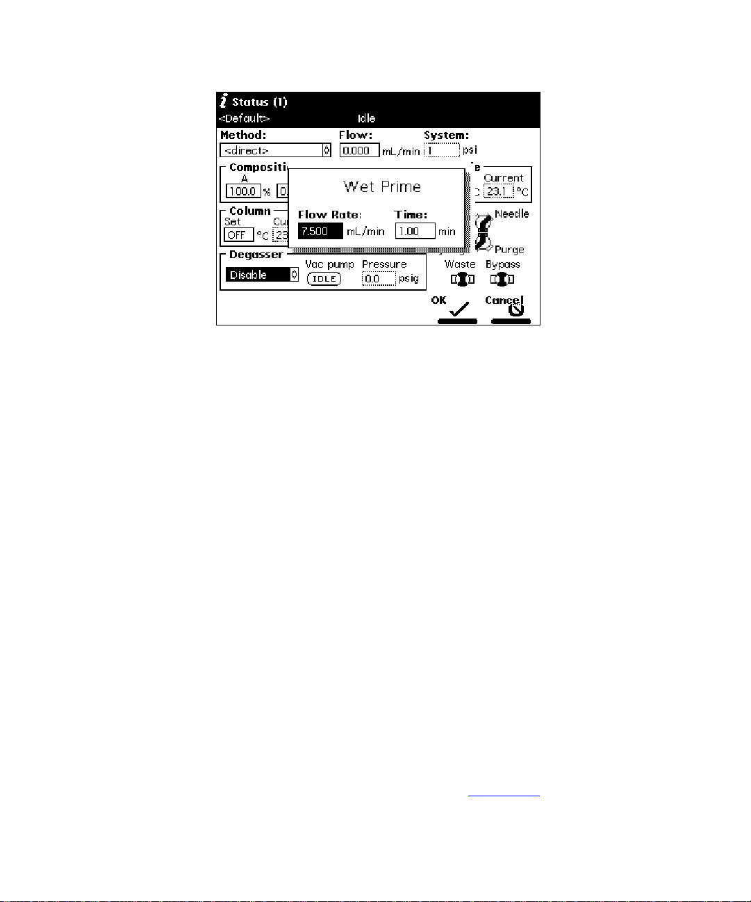
Figure 2-5 Wet Prime Dialog Box
5. Gently shake the filters in the reservoirs to remove any bubbles that may have
formed.
6. Enter the flow rate and time (duration) to prime (using the composition entered in
the Status screen), then press the
system begins the priming function.
At the end of the time period you specify, the solvent management system
returns to the previous conditions, and the 2790 enters the Idle mode.
7. Repeat steps 1 to 5 for each solvent, as appropriate.
screen key. The solvent management
OK
Equilibrating Solvents in the Vacuum Degasser
Wet priming occurs at flow rates that do not allow for thorough solvent degassing.
Therefore, after you perform a wet prime, the solvent remaining in the degasser chamber
lines needs to be degassed before solvent flow resumes. This is accomplished by setting a
zero flow rate for a short time period.
For more information on vacuum degassing, refer to the
Operator’s Guide
Vacuum Degasser” discussion.
To equilibrate solvents in the in-line vacuum degasser after you have wet primed the
system:
1. Press
2. E nter the initial solvent composition for the run.
, Section 1.2.2, Solvent Management System Features, the “In-Line
Menu/Status
to display the Status screen (Figure 1-14
Waters 2790 Separations Module
).
Performing Direct Functions 45
Page 46

3. S et the Degasser Mode parameter to
Normal
or
Continuous
.
4. P ress the
(Figure 2-2
5. Select
(Figure 2-5
6. Enter a flow rate of
key. At the end of the time per iod, the solvents are degassed and the 2790
enters the Idle mode.
The solvents in the in-line vacuum degasser are now equilibrated and the 2790 is
prepared to run.
Direct Function
).
Wet Prime
).
, then press
0.000
screen key. The Direct Functions list appears
. The Wet Prime dialog box appears
Enter
mL/min. and time of 5 min, then press the
2.2.3 Purging the 410 or 2410 Reference Cell
Purge the 410 or 2410 RI detector reference cell (and fluidic path) when you change
solvents or experience an unexpected loss in sensitivity due to excess noise or drift.
To purge the 410 or 2410 reference cell:
1. Press
2. E nter the flow rate and composition with which to purge the 410 or 2410
3. P ress the
Menu/Status
reference cell.
Direct Function
(Figure 2-2
).
to display the Status screen (Figure 1-14
screen key. The Direct Functions list appears
screen
OK
).
4. Select
appears (Figure 2-6
5. E nter the am ount of time (in minutes) to pump fresh solvent through the
reference cell, then press the OK screen key. The timer counts down as the
solvent is pumped through the detector reference cell.
46 Performing Direct Functions
Purge 410/2410
, then press
).
. The Purge 410/2410 dialog box
Enter
Page 47

Figure 2-6 Purge 410/2410 Dialog Box
2.2.4 Washing the Needle
The Wash Needle f unct ion:
• Washes the inject port and the interior and exterior of the needle
• Flushes the wash solvent out of the needle and inject port and replaces it with
degassed purge solvent
Use the Wash Needle function to:
• Ensure that the needle and inject por t are clean before the start of a new method
• V erify that the needle-wash system is primed and operating properly by checking for
flow through the waste tube
If the 2790 does not detect that a needle wash was performed since the last time
Note:
the 2790 was powered on, it performs an automatic needle wash before beginning any
injections, either those specified in a sample set or by using the Inject Samples direct
function.
Waters recommends using a high percentage organic wash solvent that is
Note:
compatible with your mobile phase and sample diluent, such as methanol or acetonitrile.
See Tab le 1-4.
STOP
Attention:
wash (see Section 1.4.1,
Make sure the needle-wash solvent line is primed before you perform a needle
Priming the Needle-Wash Pump).
Performing Direct Functions 47
Page 48

To wash the needle:
1. Press
Menu/Status
2. Press the
(Figure 2-2
3. Select
Wash Needle
(Figure 2-7
to display the Status screen (Figure 1-14
Direct Function
screen key. The Direct Functions list appears
).
, then press
Enter
).
Figure 2-7 Wash Needle Dialog Box
).
. The Wash Needle dialog box appears
4. E nter the number of wash cycles in the Wash cycles field (the default is 1).
5. E nter the am ount of time (in seconds) to wash the inject port and the needle
exterior in the appropriate fields.
6. Enter the replacement volume of degassed solvent in the appropriate field. Start
with
7. P ress the
µ
L replacement volume.
600
screen key. The Wash Needle cycle begins.
OK
If necessary, press the
suspend the wash cycle. When solvent flow stops, press the
screen key to end the Wash Needle cycle.
At the end of the final wash cycle, the Wash Needle function automatically flushes out the
needle-wash solvent and replaces it with degassed purge solvent.
48 Performing Direct Functions
Stop WashNdl
screen key or the
Stop Flow
key to
Abort WashNdl
Page 49

2.2.5 Equilibrating the System
During equilibration of the HPLC or LC/MS system, the 2790 delivers solvents and
maintains separation parameters (such as sample and column temperature, degasser
operation, and so on) at the conditions shown in the Status screen. The time needed to
equilibrate the system depends on environmental and application-specific factors.
To equilibrate the system:
1. Press
2. E nter the desired initial conditions. Alternatively, in the Method field, select the
3. P ress the
4. Select
Menu/Status
separation method that contains the initial conditions for equilibration.
Direct Function
(Figure 2-2
(Figure 2-8
).
Equilibrate
).
to display the Status screen (Figure 1-14
screen key. The Direct Functions list appears
, then press
. The Equilibrate dialog box appears
Enter
).
Figure 2-8 Equilibrate Dialog Box
5. E nter the am ount of time to equilibrate the system and the column position to
equilibrate (if applicable).
6. P ress the OK screen key. When the equilibration period ends, the 2790 enters
the Idle state. The flow rate remains at the value in the Flow field in the Status
screen.
Performing Direct Functions 49
Page 50

2.2.6 Conditioning the Column
Conditioning the column involves running a solvent gradient through the column without
injecting samples or running the Events table. You select a separation method (see the
Waters 2790 Separations Module Operator’s Guide
Separation Methods and Sample Sets) that contains the gradient parameters you want to
use, then the 2790 runs the gradient.
, Chapter 5, Creating and Editing
To run timed events without injecting a sample, select the
Note:
Inject Samples
option
from the Direct Functions list and enter an injection volume of 0 (see Section 2.2.7,
Injec ting Samples).
To condition the column:
1. Press
2. I n the Method drop-down list, select the separation method with the gradient
3. P ress the
4. Select
Menu/Status
parameters you want to use to condition the column, then press
Direct Function
(Figure 2-2
appears (Figure 2-9
).
Condition Column
to display the Status screen.
screen key. The Direct Functions list appears
, then press
).
. The Condition Column dialog box
Enter
Enter
.
Figure 2-9 Condition Column Dialog Box
5. I n the Column field, enter the column position to condition (if applicable).
50 Performing Direct Functions
Page 51

6. I n the Time f ield, enter the amount of time to c ondition the column. Ensure that
the time is equal to or greater than the time for the gradient defined in the
selected separation method plus any reequilibration time.
7. P ress the OK screen key. The solvent management system r uns the column
conditioning procedure for the specified time.
2.2.7 Injecting Samples
Using the front panel, you can inject one or more samples from one or more wells in a
sample plate. If no separation method is selected, the 2790 uses the instrument conditions
displayed in the Status screen. You c an use gradients and timed events by selecting a
separation method in the Method field. The current separation method is displayed in the
banner area.
STOP
Attention:
If you make any changes to an existing method in the Status screen, the
Method field changes to <direct>, the separation method name in the banner area is
enclosed within angle brackets (< >), and the current isocratic conditions (with no timed
events) are applied.
To inject a sa mp l e :
1. Place the prepared sample(s) or vial(s) into a plate, then insert the plate in the
sample compartment (see the
Section 3.4.3, Loading the Sample Plates).
2. Close t he sample compar t ment door.
3. Press
4. E nter the initial conditions. Alternatively, you can select
5. P ress the
6. Select
Menu/Status
separation method that contains the conditions to perform the injection.
Direct Function
(Figure 2-2
(Figure 2-10
in the Inject Samples dialog box.
).
Inject Samples
), displaying six parameter fields. Table 2-2 descri bes the parameters
to display the Status screen (Figure 1-14
, then press
Waters 2790 Separations Module Operator’s Guide
).
Method
screen key. The Direct Functions list appears
. The Inject Samples dialog box appears
Enter
, then select the
,
Performing Direct Functions 51
Page 52

Figure 2-10 Inject Samples Dialog Box
7. E nter a value in each field, then press
Enter
.
8. P ress the OK screen key to begin the injection(s), or press
the previous screen without injecting any samples.
Cancel
to re tu rn to
52 Performing Direct Functions
Page 53

Table 2-2 Inject Samples Dialog Box Parameters
Parameter Description Value Range
Location Specifies the plate carrier location. 1 to 4
Type Specifies the plate type. One of up to 15 (see
Section 1.2.5, Configuring Plate
Types)
Well(s) Specifies the well number or range
from which you want to make
injections.
Alternatively, you can press the
screen key to select one or more
wells using the Well Selector (see
Section 2.2.8,
Making Injections).
When entering a well range, use the •
key to separate entries. For example,
to inject samples from wells 1 through
20, enter
Inject(s) Specifies the number of injections per
well.
Volume Specifies the volume for each
injection. See the
Selecting Wells for
.
1.20
Waters 2790
Plate
Separations Module Operator’s
Guide
, Section 5.3.7, Setting Sample
Set Parameter Values, the “Injection
Volume” discussion.
Depending on plate type,
1 to 24, 48, 96, or 384
1 to 99
Maximum injection volum e
depends on the size of the
sample loop or 60% of syringe
volume, whichever is smaller.
If the most recently
Note:
applied separation method
specifies a Full Loop, then the
Volume field is not editable. See
the Waters 2790 Separations
Module Operator’s Guide,
Section 5.1, Creating and
Editing Separation Methods.
Run time Specifies the run time for each
injection
0 to 999.99 in minutes
Performing Direct Functions 53
Page 54

2.2.8 Selecting Wells for Making Injections
You can specify the well(s) from which to make injections by using the Well Selector
function. This function is available from any screen that displays the Plate screen key
(Configuration, Sample Set, and Run Samples screens).
To access the Well Selector when you are performing an Inject Samples direct function
(Figure 2-10
), press the
screen key. The Well Selector is displayed (Figure 2-11).
Plate
Well Location
(Plate Logic)
Well Locati on
(Numeric Identifier)
Number of W ells
Selected
Range of
Selected Wells
Sequential
Reference
To select the plate type:
1. Press the
screen key, then select from the drop-down list of available plate
Type
types.
2. Press
to accept the selected plate, or press the
Enter
return to the Well Selector without making a selection.
To select a single well:
1. Press the
Set by Number
can use the arrow keys to move to the specific well you want to specify.
2. Press • to set the selected well, or press
switch a well to its opposite state (selected to deselected or vice versa), press
.
Enter
To select all the wells on the selected plate, press the
name changes to
54 Performing Direct Functions
Clear All
Figure 2-11 Well Selector
Cancel
screen key to
screen key, then enter the well number. Alternatively, you
to clear the selected well. To
Clear
Select All
screen key. The key
.
Page 55

To deselect all selected wells on the selected plate, press the
key name changes to
To select a group of wells (two or more) in a rectangular area of the selected plate:
Select All
.
Clear All
screen key. The
1. Press the
2. Us e the arrow keys to outline the group of wells.
3. Press • to set all the selected wells, or press
switch each well in a group to its opposite state (selected to deselected or vice
versa), press
Press the
Press the OK screen key after you have selected a group of wells to return to the Inject
Samples dialog box or the sample set table, or press the
the Inject Samples dialog box without specifying one or more wells graphically .
When a collection contains noncontiguous wells, the wells are indicated in the
Note:
Start Group
Enter
screen key to print the Well Selector page currently displayed.
Print
screen key.
.
to clear the selected wells. To
Clear
Cancel
screen key to return to
Well(s) field of the Inject Samples dialog box or the Sample Set table by the total number
of wells in square brackets ([…]). See the Waters 2790 Separations Module Operator’s
Guide, Section 5.3, Creating and Editing Sample Sets, for more information.
The 2790 provides predefined as well as custom plate types. For more information,
Note:
see Section 1.2.5 ,
Configuring Plate Types.
Performing Direct Functions 55
Page 56

3
Creating Meth ods
This section provides an overview of creating methods when the 2790 is in a standalone
mode (System Controller or No Interaction). To create methods when the 2790 is under
control of the MassLynx software, refer to the
Waters Alliance LC/ M S Quick Star t Guide
.
The term
chromatographically separated. There are two kinds of methods:
For complete information on creating and editing separation method s and sample sets,
see the
Editing Separation Methods and Sample Sets.
method
•
Separat i on m et h od
influence the separation.
•
Sample set
separation methods.
Waters 2790 Separations Module Operator’s Guide
refers to the instructions that define how your samples are
– A set of time-based and nontime-based conditions that
– A set of instructions in table format that applies functions to
, Chapter 5, Creating and
Separation Methods
Some of the conditions you can specify in a separation method are:
• Mobile phase composition and flow rate
• Sample temperature
• Column temperature
• I/O parameters
• Column selection
• Normal or high-throughput injection modes
• Autosampler parameters
• Full and partial loop control
56 Creating Methods
Page 57

Sample Sets
A sample set applies the following functions to a separation method:
• Inject samples or standards
• Auto standards
• Refresh syringe
•Prime
• Condition column
• Equilibrate
• Wash needle
• Pool
• Auto add
The Pool and Auto Add functions are available only when the 2790 is configured in
Note:
a standalone mode (System Controller or No Interaction).
You can use multiple separation methods in a sample set.
You create and edit separation methods and sampl e sets using the Meth ods screen
(Figure 3-1
identified by a chromatogram icon and sample sets are identified by a multiple vial
icon .
) and six associated screens. In the Methods screen, separation methods are
Figure 3-1 Methods Screen
Performing Direct Functions 57
Page 58

3.1 Creating Sep aration Methods
To create a separation method using the 2790 front panel:
1. Press the
appears (Figure 3-1
2. P ress the
3. P ress the c hromatogram icon (separation method) screen key. The
Separation Method Name dialog box appears (Figure 3-3
Develop Methods
).
screen key. The New Method dialog box appears (Figure 3-2
New
Figure 3-2 New Method Dialog Box
screen key in the Main screen. The Methods screen
).
).
58 Creating Methods
Page 59

Figure 3-3 Separation Method Name Dialog Box
4. Us e the s creen keys to enter a name of up to 30 characters (see the
2790 Separations Module Operator’s Guide
, Section 3.1.2, Using the Keypad,
the “Entering an Alphanumeric String” discussion).
5. Press
. The Mobile Phase screen appears (Figure 3-4
Enter
). This screen is one
of six parameter screens. The other five parameter screens are Sample,
Autosampler, Column, I/O, and Detectors.
Figure 3-4 Mobile Phase Screen
Waters
Creating Separation Methods 59
Page 60

6. S elect values for the parameter fields in the Mobile Phase screen, using the
arrow keys to move between fields (see the
Operator’s Guide
, Section 5.2, Setting Separation Method Parameters).
Waters 2790 Separations Module
7. P ress the
parameter screens.
8. Select values for the par ameter fields in each of the other five separation method
parameter screens. Refer to the
Guide
, Section 5.2, Setting Separation Method Parameters, for details on
specifying parameter values in separation methods.
9. To save the new method, press
screen key.
Next
or
Previous
screen key to navigate among the six method
3.2 Creating Sample S ets
To create a sample set:
1. Press the
appears (Figure 3-1
2. P ress the
3. P ress the multiple vial icon
dialog box appears.
4. E nter a name of up to 30 characters (see the
Operator’s Guide
5. Press
Develop Methods
).
screen key. The New Method dialog box appears (Figure 3-2
New
, Section 3.1.2, Using the Keypad).
. The Sample Set screen appears (Figure 3-5
Enter
screen key in the Main screen. The Methods screen
Waters 2790 Separations Module Operator’s
. When prompted to save, press the
Exit
(sample set) screen ke y. The Sample Set Name
Yes
).
Waters 2790 Separations Module
).
When the Sample Set screen appears initially, it is in the Functional View (see the
Note:
Waters 2790 Separations Module Operator’s Guide, Section 5.3.6, Viewing Sample Sets).
60 Creating Methods
Page 61

Plate Position
Injections
per Well
Volume per
Injecti on
Well Range
or Collection
Figure 3-5 Sample Set Screen (Functional View)
6. E nter parameter values in the sample set table as appropriate (see the
2790 Separations Module Operator’s Guide
, Sectio n 5.3.7, Settin g Sample Se t
Parameter Values, and Section 5.3.8, Setting Sample Set Functions).
7. When you finish entering values and functions in the sample set table, press
, then press the
Exit
To exit without saving the sample set, press the
screen key to save the sample set.
Yes
No
screen key.
To return to the sample set without entering any changes, press the
screen key.
Run
Time
Cancel
Waters
Creating Sample Sets 61
Page 62
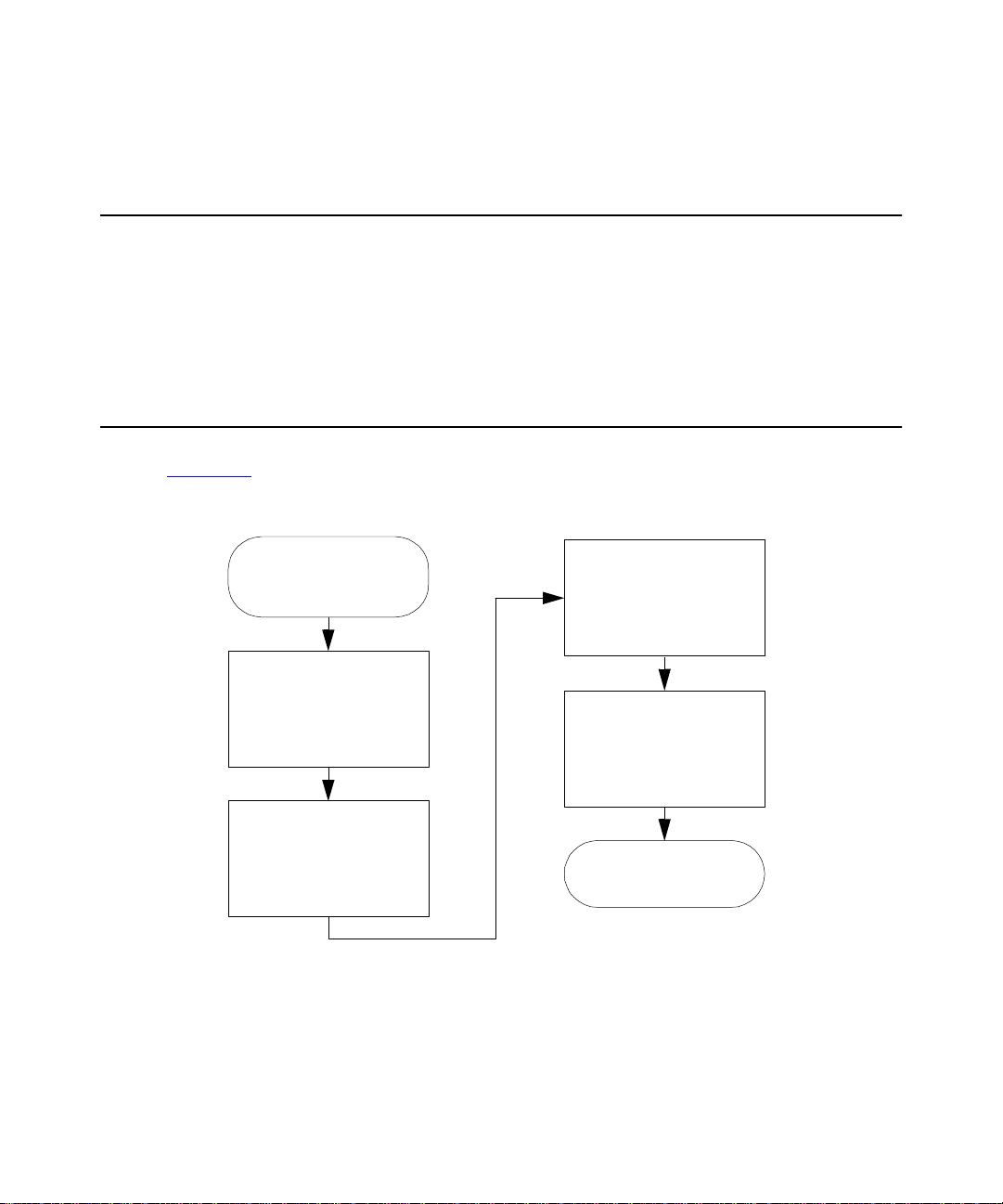
4
Making Automatic Runs
This section provides an overview of the steps to running methods and sample sets,
performing preventive maintenance, and powering off the 2790. For information on
high-throughput applications, see the
Section 6.2, Using the 2790 High-Throughput Capabilities.
4.1 Making Automatic Runs in a Stand-Alone Mode
Figure 4-1 summarizes the steps for making an automatic run in a stand-alone mode
(System Controller or No Interaction).
Run Samples
Press
in the Main Screen
Waters 2790 Separations Module Operator’ s Guide
Enter the Appropriate
Information to Complete
the Sample Set
Operating Condi tions
,
Select the Separation
Method or Sample Set
to Run
Run
Press
Conditions
Solvent Management
Figure 4-1 Making an Automatic Run in a Stand-Alone Mode
62 Making Automatic Runs
to Proceed,
or Press
to Start the
System
Initial
Press the
Screen K ey to Begin
The R u n E nds as
Routine
the Run
Programmed
Page 63

4.1.1 Running a Sample Set
Refer to the Waters 2790 Separations Module Operator’s Guide, Chapter 5,
Note:
Creating and Editing Separation Methods and Sample Sets, for information on creating,
storing, and importing separation methods and sample sets.
To run a sample set in a stand-alone (System Controller or No Interaction) mode:
1. Press the
appears (Figure 4-2
2. S elect a sample set or separation method, then press one of the following
screen keys (or press the
sample set from a floppy disk):
Run Samples
screen key in the Main screen. The Run Samples screen
), listing the available separation methods and sample sets.
Figure 4-2 Run Samples Screen
Import
screen key to import a separation method or
•
Initial Conds
specified in the first line of the sample s et and begins equilib rating th e
temperature in the sample heater/cooler and column heater. When the system
is equilibrated, press the
•
– Displays the selected sample set table (to view or edit) as show n in
Run
Figure 4-3
– Starts the solvent management system at the initial conditions
screen key.
Run
. Use the screen keys to modify the table.
Making Automati c Runs in a Stand-Alone Mode 63
Page 64

Figure 4-3 Run Samples Screen (Functional View)
You can modify the sample set before you press the
Note:
3. Load the samples into the plate(s), according to the locations specified in the
sample set (see Section 1.4.3,
Loading, and Plate Loading views to view the sample set (see the
Separations Module Operator’s Guide
If necessary, modify the sample set. Press the
the modified sample set as a new method.
You can edit a sample set only in the Functional view.
Note:
4. P ress the
Check that the information in this screen is correct.
5. I f a printer is connected to your system, press the
contents of the Requirements screen and a listing of the injections.
6. P ress the
key to make a STAT run.
To make a STAT run, or to modify a run in progress, refer to Section 4.1.2,
Modifying a Sample Set During a Run.
screen key. The Requirements screen appears (Figure 4-4).
Start
Routine
screen key to start a normal run, or press the
Loading the Sample Plates). Use the Injection,
, Section 5.3.6, Viewing Sample Sets).
Save Method
screen key to print the
Print
screen key.
Start
Waters 2790
screen key to save
STAT
screen
64 Making Automatic Runs
Page 65

Figure 4-4 Requirements Screen
4.1.2 Modifying a Sample Set During a Run
You can modify operating conditions during a run in a stand-alone mode by:
• Performing a STAT run
• Editing the separation method
Performing a STAT Run
Use the STAT run function to interrupt a run in progress, perform one or more injections
after the current injection is done, then continue with the scheduled run. Performing a
STA T run is most useful when the separation methods for the STAT run and the scheduled
run use identical solvents and temperatures.
STOP
Attention:
you start a STAT run, the plate carrier cannot move and a warning message is displayed if
a plate position change is specified. Wait for the sample injection to finish before
continuing.
To perform a STAT run while a samp le set is running:
1. Load the ST AT run samples into the sample plate, then place the plate in the sample
2. P ress the
If the 2790 sample management system is drawing or injecting a sample when
compar t men t and close the sample com partment door.
Run Samples
screen appears (Figure 4-2
screen key in the Main screen. The Run Samples
).
Making Automati c Runs in a Stand-Alone Mode 65
Page 66

3. S elect the separation method or sampl e set to use for the STAT run, then press
the
4. E nter the well position(s) and other parameters in the appropriate fields.
5. P ress the
Check that all information in this screen is correct.
screen key.
Run
screen key. The Requirements screen appears (Figure 4-4
Start
).
6. P ress the
After the STAT run is complete, the original run resumes imm ediately.
STAT
screen key.
Modifying a Separation Method During a Run
You can modify a separation method while a sample set is running.
If the separation method you are modifying is being used for the current injection, the
current injection is not affected by the changes. You need to save the changes to the
separation method before you can apply the modified separation method to any
subsequent injections. Use the procedures in the
Operator’s Guide
separation method.
, Section 5.1.2, Editing Separation Methods, to modify and save the
4.1.3 Stopping a Run
To stop a run in progress, press one of the following keys in the Status screen:
•
Stop (Function)
screen keys to
•
Hold (Function)
operation of subsequent functions, and displays screen keys that allow you to abort
or resume the sample set.
•
Hold Gradient
allows you to resume the gradient.
screen key – Stops the current function and changes the Status
and
Abort
screen key – Allows the current function to finish, suspends
screen key – Maintains the current gradient conditions. A screen key
Resume
Waters 2790 Separations Module
(see below).
•
Stop Flow
current function, and displays screen keys that allow you to abort or resume the
function.
If any alarm condition specified in the separation method or sample set is set to “Stop
Function” or “Stop Flow” and the alarm condition occurs, a dialog box appears indicating
the alarm condition and displaying the following screen keys:
•
Abort
•
Resume
66 Making Automatic Runs
keypad key – Stops the flow of solvent, suspends operation of the
– Cancels the current function
– Resumes the current function
Page 67

4.2 Performing Preventive Maintenance
To assess the need for preventive maintenance on your 2790:
1. Press the
(Figure 4-5
• Transducers fields – Display the current pressure readings for the two
transducers.
• Lifetime Counters fields – Display total values for the volume of eluent and the
number of injections.
Use this information to assess the requirements for pre v entive maintenance (see
the
Waters 2790 Separations Module Operator’s G uide
Maintenance Considerations, the “Recommended Preventive Maintenance
Schedule” discussion).
screen key in the Main screen. The Diagnostics screen appears
Diag
) with the following fields:
, Section 7.1,
C99SM9000N
Figure 4-5 Diagnostics Screen
2. P ress the s creen key corresponding to the par t of the 2790 you want to
troubleshoot.
Performing Preventive Maintenance 67
Page 68

4.3 Powering Off the 2790
Before Powering Off
Before you power off the 2790 for more than a few days, remove any buffered mobile
phase present in the fluidic path.
Attention:
STOP
following procedure.
To remove buffered mobile phase from the fluidic path:
P o w e ring Off
To power off the 2790:
To avoid damaging the column, remove the column before performing the
1. Replace the buffered mobile phase with HPLC-quality water and wet prime the
system for 10 minutes a t 3 mL/min (see Section 2.2.2,
2. Replace the water in the fluidic path with a solution of 90% water:10% methanol,
and flush the system for 10 minutes at 3 mL/m in .
1. Ensure that the system has been flushed (see the “
above).
2. Press the power switch to t he (Off) 0 position. The time and dat e of the power-off
are entered in the log file.
Wet Priming).
Before Powering Off” discus sion
68 Making Automatic Runs
 Loading...