

Page 1

Waters 2410
Differential Refractometer
Operator’s Guide
34 Maple Street
Milford, MA 01757
71500241002, Revision 3
Page 2

NOTICE
The information in this document is subject to change without notice and should not be construed
as a commitment by Waters® Corporation. Waters Corporation assumes no responsibility for any
errors that may appear in this document. This guide is believed to be complete and accurate at the
time of publication. In no event shall Waters Corporation be liable for incidental or consequential
damages in connection with or arising from the use of this guide.
2001 WATERS CORPORATION. PRINTED IN THE UNITED STATES OF AMERICA.
ALL RIGHTS RESERVED. THIS DOCUMENT OR PARTS THEREOF MAY NOT BE
REPRODUCED IN ANY FORM WITHOUT THE WRITTEN PERMISSION OF THE
PUBLISHER.
Millennium® PIC and Waters are registered trademarks, and busLAC/E and PowerStation are trademarks of
Waters Corporation.
Micromass is a registered trademark and MassLynx is a trademark of Micromass Ltd.
All other trademarks or registered trademarks are the sole property of their respective owners.
Page 3

Note
: When you use the instrument, follow generally accepted procedures for quality
control and methods development.
If you observe a change in the retention of a particular compound, in the resolution
between two compounds, or in peak shape, immediately take steps to determine the
reason for the changes. Until you determine the cause of a change, do not rely upon the
results of the separations.
Note:
The installation category (Overvoltage Category) for this instrument is Level II. The
Level II category pertains to equipment that receives its electrical power from a local lev el,
such as an electrical wall outlet.
STOP
Attention:
responsible for compliance could void the user’s authority to operate the equipment.
Important:
par l’autorité résponsable de la conformité à la réglementation peut annuler de droit de
l’utilisateur à exploiter l’équipement.
Achtung
ausdrückliche Genehmigung der für die ordnungsgemäße Funktionstüchtigkeit
verantwortlichen Personen kann zum Entzug der Bedienungsbefugnis des Systems
führen.
Avvertenza:
espressamente approvate da un ente responsabile per la conformità annulleranno
l’autorità dell’utente ad operare l’apparecchiatura.
Atención
expresamente aprobado por la parte responsable del cumplimiento puede anular la
autorización de la que goza el usario para utizar el equipo.
Changes or modifications to this unit not expressly approved by the party
Toute modefication sur cette unité n’ayant pas été expressément approuvée
: Jedewede Änderungen oder Modifikationen an dem Gerät ohne die
eventuali modifiche o alterazioni apportate a questa unità e non
: cualquier cambio o modificación realizado a esta unidad que no haya sido
Page 4

Caution:
Use caution when working with any polymer tubing under pressure:
• Always wear eye protection when near pressurized polymer tubing.
• Extinguish all nearby flames.
• Do not use Tefzel tubing that has been severely stressed or kinked.
• Do not use Tefzel tubing with tetrahydrofuran (THF) or concentrated nitric or
sulfuric acids.
• Be aware that methylene chloride and dimethyl sulfoxide cause Tefzel tubing to
swell, which greatly reduces the rupture pressure of the tubing.
Attention
pression:
Vorsicht
angebracht:
: soyez très prudent en travaillant avec des tuyaux de polymères sous
• Portez toujours des lunettes de protection quand vous vous trouvez à proximité
de tuyaux de polymères.
• Eteignez toutes les flammes se trouvant à proximité.
• N'utilisez pas de tuyau de Tefzel fortement abîmé ou déformé.
• N'utilisez pas de tuyau de Tefzel avec de l'acide sulfurique ou nitrique, ou du
tétrahydrofurane (THT).
• Sachez que le chlorure de méthylène et le sulfoxyde de diméthyle peuvent
provoquer le gonflement des tuyaux de Tefzel, diminuant ainsi fortement leur
pression de rupture.
: Bei der Arbeit mit Polymerschläuchen unter Druck ist besondere Vorsicht
• In der Nähe von unter Druck stehenden Polymerschläuchen stets Schutzbrille
tragen.
• Alle offenen Flammen in der Nähe löschen.
• Keine Tefzel-Schläuche verwenden, die stark geknickt oder überbeansprucht
sind.
• Tefzel-Schläuche nicht für Tetrahydrofuran (THF) oder konzentrierte Salpeteroder Schwefelsäure verwenden.
• Durch Methylenchlorid und Dimethylsulfoxid können Tefzel-Schläuche quellen;
dadurch wird der Berstdruck des Schlauches erheblich reduziert.
Page 5

Precauzione
pressione:
• Indossare sempre occhiali da lavoro protettivi nei pressi di tubi di polimero
pressurizzati.
• Estinguere ogni fonte di ignizione circostante.
• Non utilizzare tubi Tefzel soggetti a sollecitazioni eccessive o incurvati.
• Non utilizzare tubi Tefzel contenenti tetraidrofurano (THF) o acido solforico o
nitrico concentrato.
• Tenere presente che il cloruro di metilene e il dimetilsolfossido provocano
rigonfiamento nei tubi Tefzel, che riducono notevolmente il limite di pressione di
rottura dei tubi stessi.
: prestare attenzione durante le operazioni con i tubi di polimero sotto
Advertencia:
• Protegerse siempre los ojos a proximidad de tubos de polimero bajo presión.
• Apagar todas las llamas que estén a proximidad.
• No utilizar tubos Tefzel que hayan sufrido tensiones extremas o hayan sido
• doblados.
• No utilizar tubos Tefzel con tetrahidrofurano o ácidos nítrico o sulfúrico
concentrados.
• No olvidar que el cloruro de metileno y el óxido de azufre dimetilo inflan los tubos
Tefzel lo que reduce en gran medida la presión de ruptura de los tubos.
manipular con precaución los tubos de polimero bajo presión:
Page 6

Caution:
specified by the manufacturer, the protection provided by the equipment may be
impaired.
The user shall be made aware that if the equipment is used in a manner not
Attention:
spécifiée par le fabricant, la protection assurée par le matériel risque d’être
défectueuses.
Vorsicht:
Verwenddung des Gerätes unter Umständen nicht ordnungsgemäß funktionieren.
Precauzione:
usta in un modo specificato dal produttore, la protezione fornita dall’apparecchiatura
potrà essere invalidata.
Advertencia:
especificada por el fabricante, las medidas de protección del equipo podrían ser
insuficientes.
Caution:
rating.
Attention:
puissance afin d’éviter tout risque d’incendie.
Vorsicht:
gleichen Typs und Nennwertes ersetzen.
Precauzione:
con altri dello stesso tipo e amperaggio.
L’utilisateur doit être informé que si le matériel est utilisé d’une façon non
Der Benutzer wird darauf aufmerksam gemacht, dass bei unsachgemäßer
l’utente deve essere al corrente del fatto che, se l’apparecchiatura viene
El usuario deberá saber que si el equipo se utiliza de forma distinta a la
To protect against fire hazard, replace fuses with those of the same type and
Remplacez toujours les fusibles par d’autres du même type et de la même
Zum Schutz gegen Feuergefahr die Sicherungen nur mit Sicherungen des
per una buona protezione contro i rischi di incendio, sostituire i fusibili
Precaución:
el riesgo de incendio.
sustituya los fusibles por otros del mismo tipo y características para evitar
Page 7

Caution:
power cord before servicing the instrument.
To avoid possible electrical shock, power off the instrument and disconnect the
Attention:
l’instrument et débranchez le cordon d’alimentation de la prise avant d’effectuer la
maintenance de l’instrument.
Vorsicht:
abgeschaltet und vom Netz getrennt werden.
Precauzione:
il cavo di alimentazione prima di svolgere la manutenzione dello strumento.
Precaución:
de alimentación antes de realizar cualquier reparación en el instrumento.
Afin d’éviter toute possibilité de commotion électrique, mettez hors tension
Zur Vermeidung von Stromschlägen sollte das Gerät vor der Wartung
per evitare il rischio di scossa elettrica, spegnere lo strumento e scollegare
para evitar choques eléctricos, apague el instrumento y desenchufe el cab le
Page 8

Commonly Used Symbols
Direct current
Courant continu
Gleichstrom
Corrente continua
Corriente continua
Alternating current
Courant alternatif
Wechs el s t r om
Corrente alternata
Corriente alterna
Protective conductor terminal
Borne du conducteur de protection
Schutzleiteranschluss
Terminale di conduttore con protezione
Borne del conductor de tierra
Frame or chassis terminal
Borne du cadre ou du châssis
Rahmen- oder Chassisanschluss
Terminale di struttura o telaio
Borne de la estructura o del chasis
Caution or refer to manual
Attention ou reportez-vous au guide
Vorsicht, oder lesen Sie das Handbuch
Prestare attenzione o fare riferimento alla guida
Actúe con precaución o consulte la guía
Page 9

Commonly Used Symbols
Caution, hot surface or high temperature
Attention, surface chaude ou température élevée
Vorsicht, heiße Oberfläche oder hohe Temperatur
Precauzione, superficie calda o elevata temperatura
Precaución, superficie caliente o temperatura elevada
Caution, risk of electric shock (high voltage)•Attention,
risque de commotion électrique (haute tension)
Vorsicht, Elektroschockgefahr (Hochspannung)
Precauzione, rischio di scossa elettrica (alta tensione)
Precaución, peligro de descarga eléctrica (alta tensión)
Caution, risk of needle-stick puncture
Attention, risques de perforation de la taille d’une aiguille
Vorsicht, Gefahr einer Spritzenpunktierung
Precauzione, rischio di puntura con ago
Precaución, riesgo de punción con aguja
(Continued)
Caution, ultraviolet light
Attention, rayonnement ultrviolet
Vorsicht, Ultraviolettes Licht
Precauzione, luce ultravioletta
Precaución, emisiones de luz ultravioleta
Page 10

Waters 2410 Differential Refractometer Information
Intended Use
The W aters® 2410 Differential Refractometer can be used for in-vitro diagnostic testing to analyze
many compounds, including diagnostic indicators and therapeutically monitoredcompounds. When
you develop methods, follow the “Protocol for the Adoption ofAnalytical Methods in the Clinical
Chemistry Laboratory,” American Journal ofMedical Technology, 44, 1, pages 30–37 (1978). This
protocol covers good operatingprocedures and techniques necessary to validate system and method
performance.
Biological Hazard
When you analyze physiological fluids, take all necessary precautions and treat all specimens as
potentially infectious. Precautions are outlined in “CDC Guidelines on Specimen Handling,” CDC
– NIH Manual, 1984.
Calibration
Follow acceptable methods of calibration with pure standards to calibrate methods. Use a minimum
of five standards to generate a standard curve. The concentration range should cover the entire
range of quality-control samples, typical specimens, and atypical specimens.
Quality Control
Routinely run three quality-control samples. Quality-control samples should represent subnormal,
normal, and above-normal levels of a compound. Ensure that quality-control sample results are
within an acceptable range, and evaluate precision from day to day and run to run. Data collected
when quality-control samples are out of range may not be valid. Do not report this data until you
ensure that chromatographic system performance is acceptable.
Page 11

Table of Contents
How to Use This Guide
Chapter 1
Waters 2410 Theory of Operation
1.1 Overview.........................................................................................................1-1
1.2 Theory of Operation........................................................................................ 1-2
1.2.1 Optical Refraction .............................................................................1-2
1.2.2 Differential Refractometry ................................................................1-7
1.2.3 Common RI Detection Problems ...................................................... 1-9
1.3 Principles of Operation.................................................................................. 1-10
1.3.1 Fluidics............................................................................................. 1-10
1.3.2 Optics .............................................................................................. 1-14
1.3.3 Electronics .......................................................................................1-15
Chapter 2
Installing the 2410 Refractometer
2.1 Introduction.....................................................................................................2-1
2.2 Site Selection and Power Requirements.......................................................... 2-2
2.3 Unpacking and Inspection............................................................................... 2-4
2.4 Making Electrical Power Connections............................................................ 2-5
2.5 Making Fluidic Connections...........................................................................2-5
2.5.1 Connecting a Column or Second Detector.........................................2-6
2.5.2 Connecting to Waste ......................................................................... 2-7
2.5.3 Connecting to a Drip Tray .................................................................2-8
Table of Contents xi
Page 12

Chapter 3
Making Signal Connections
3.1 Component Connection Overview.................................................................. 3-1
3.2 Making IEEE-488 Signal Connections ........................................................... 3-3
3.2.1 Connecting to a Waters Data System Using the IEEE-488 Bus ........3-3
3.2.2 Connecting to a Waters PowerLine System Controller ..................... 3-7
3.2.3 Connecting to a Manual Injector .......................................................3-7
3.3 Making Non-IEEE-488 Signal Connections................................................... 3-8
3.3.1 Connecting to a Stand-Alone 2690 Separations Module.................3-10
3.3.2 Connecting to the Waters 745/745B/746 Data Module .................. 3-13
3.3.3 Connecting to a Chart Recorder ...................................................... 3-15
3.3.4 Connecting to the Waters 845/860 ExpertEase System ..................3-16
3.3.5 Connecting Injection Trigger Signals .............................................3-16
3.3.6 Polarity Connections .......................................................................3-18
3.4 Connecting the External Column Heaters..................................................... 3-19
Chapter 4
Preparing Solvents
4.1 Common Solvent Problems............................................................................. 4-1
4.2 Selecting a Solvent.......................................................................................... 4-2
4.3 Solvent Degassing........................................................................................... 4-4
4.3.1 Gas Solubility.....................................................................................4-5
4.3.2 Solvent Degassing Methods .............................................................. 4-5
4.3.3 Solvent Degassing Considerations .................................................... 4-6
Chapter 5
Using the 2410 Refractometer
5.1 Using the Front Panel...................................................................................... 5-1
5.1.1 Keypad Functions .............................................................................. 5-4
5.2 Selecting Parameter Values .............................................................................5-9
xii Table of Contents
Page 13

5.2.1 Sensitivity Guidelines ........................................................................5-9
5.2.2 Scale Factor Guidelines ...................................................................5-10
5.2.3 Time Constant Guidelines ...............................................................5-11
5.2.4 Temperature Guidelines (Ext1 °C, Ext2 °C, Int °C) .......................5-12
5.2.5 Polarity Guidelines ..........................................................................5-13
5.3 Starting Up the 2410 Refractometer..............................................................5-13
5.4 Shutting Down the 2410 Refractometer........................................................5-15
Chapter 6
Maintenance Procedures
6.1 Cleaning the Fluidic Path.................................................................................6-1
6.2 Replacing Fuses...............................................................................................6-3
Chapter 7
Troubleshooting
7.1 Troubleshooting Overvie w ..............................................................................7-1
7.2 Chromatography Troubleshooting...................................................................7-2
7.2.1 Abnormal Baseline.............................................................................7-3
7.2.2 Erratic or Incorrect Retention Times .................................................7-7
7.2.3 Poor Peak Resolution ........................................................................7-9
7.2.4 Incorrect Qualitative/Quantitative Results ......................................7-11
7.3 Diagnostics ....................................................................................................7-13
7.3.1 Operating the Startup Diagnostics....................................................7-13
7.3.2 Operating the User-Initiated Diagnostics ........................................7-13
7.4 Hardware Troubleshooting ............................................................................7-16
Chapter Appendix A
Specifications
Chapter Appendix B
Spare Parts/Accessories
Table of Contents xiii
Page 14

Appendix C
Warranty Information
C.1 Limited Express Warranty...............................................................................C-1
C.2 Shipments, Damages, Claims, and Returns.....................................................C-4
Index
xiv Table of Contents
Page 15

Figures
1-1 Waters 2410 Differential Refractometer..................................................1-1
1-2 Effect of Density on RI............................................................................ 1-4
1-3 Refraction of Light................................................................................... 1-5
1-4 Presence of Sample Changes the Photodiode Signal...............................1-6
1-5 How Refraction Changes
1-6 Waters 2410 Refractometer Fluidics...................................................... 1-11
1-7 Waters 2410 Refractometer Fluidic Paths..............................................1-13
1-8 Waters 2410 Differential Refractometer Optics Bench
Assembly Light Path..............................................................................1-15
2-1 Major Steps in Installing the 2410 Differential Refractometer................2-1
2-2 Dimensions of the 2410 Refractometer ................................................... 2-2
2-3 Waters 2410 Refractometer Rear Panel ...................................................2-4
2-4 Fluidic Connections.................................................................................2-6
2-5 Ferrule and Compression Screw Assembly ............................................. 2-7
f
.......................................................................1-8
3-1 Waters 2410 Differential Refractometer Rear Panel................................ 3-2
3-2 Overview of Connecting Components to the
2410 Differential Refractometer.............................................................. 3-3
3-3 Waters Millennium System IEEE-488 Connections................................ 3-4
3-4 Waters 845/860 System IEEE-488 Connections......................................3-4
3-5 Waters Alliance System IEEE-488 Connections .....................................3-5
3-6 Waters PowerLine System Controller IEEE-488 Connections................ 3-7
3-7 Waters 2410 Rear Panel Analog-Out/Event-In Connectors.....................3-9
3-8 Auto Zero Connections Between the 2690 Separations Module
and the 2410 Refractometer................................................................... 3-11
3-9 Chart Mark Connections Between the 2690 Separations Module
and the 2410 Refractometer................................................................... 3-12
3-10 Chart Mark and Auto Zero Connections Between
the 2690 Separations Module and the 2410 Refractometer................... 3-13
Table of Contents xv
Page 16

3-11 Connections to a Waters 745/745B/746 Data Module........................... 3-14
3-12 Analog Output Connections to a Chart Recorder .................................. 3-15
3-13 Analog Output Connections to the Bus SAT/IN Module....................... 3-16
3-14 Auto Zero Connectionto a Manual Injector...........................................3-17
3-15 Chart Mark Connections to a Manual Injector ...................................... 3-18
3-16 2410 Refractometer External Column Heater Ports ..............................3-20
5-1 Display, LED Indicators, and Keypad......................................................5-2
5-2 Effects of Sensitivity Settings................................................................5-10
5-3 Effects of Filter Time Constant Settings................................................5-12
6-1 Removing and Replacing Fuses...............................................................6-4
xvi Table of Contents
Page 17

Tables
1-1 Fluidic Line Inner Diameters............................................................ 1-12
2-1 Installation Site Requirements.................................................................2-3
3-1 Component Connection Summary...........................................................3-1
3-2 Waters 2410 Refractometer Inject Start Connections........................ 3-6
3-3 Waters 2410 Connections to a Manual Injector ................................ 3-7
3-4 Waters 2410 Analog-Out/Event-In Connections............................... 3-9
3-5 Auto Zero Connections Between the 2690 Separations Module
3-6 Chart Mark Connections Between the 2690 Separations Module
3-7 Chart Mark and Auto Zero Connections Between the
3-8 Analog Output Connections to a 745/745B/746 Data Module ........ 3-13
3-9 Analog Output Connections to a Chart Recorder............................ 3-15
and the 2410 Refractometer ........................................................... 3-10
and the 2410 Refractometer ........................................................... 3-11
2690 Separations Module and the 2410 Refractometer................... 3-12
3-10 Analog Output Connections to the Bus SAT/IN Module................. 3-16
3-11 Auto Zero Connections to a Manual Injector.................................. 3-17
3-12 Chart Mark Connections to a Manual Injector ................................ 3-18
3-13 Polarity Options............................................................................. 3-19
4-1 Refractive Indices of Common Solvents..................................................4-3
5-1 Indicator LED Functions..........................................................................5-3
5-2 Keypad Functions............................................................................ 5-4
6-1 Voltage and Fuse Requirements...............................................................6-4
7-1 Abnormal Baseline Troubleshooting................................................ 7-4
7-2 Retention Time Troubleshooting...................................................... 7-7
Table of Contents xvii
Page 18

7-3 Resolution Troubleshooting ........................................................... 7-10
7-4 Incorrect Results Troubleshooting.................................................. 7-12
7-5 User Diagnostics............................................................................ 7-14
7-6 Waters 2410 Hardware Troubleshooting ......................................... 7-16
A-1 Operational Specifications...................................................................... A-1
A-2 Integrator Output..............................................................................A-2
A-3 Optical Component Specifications....................................................A-2
A-4 Environmental Specifications...........................................................A-2
A-5 Dimensions ......................................................................................A-3
A-6 Electrical Specifications...................................................................A-3
A-7 Power Source Specification..............................................................A-3
B-1 Recommended Spare Parts ...............................................................B-1
C-1 Waters 2410 Warranty Periods.................................................................C-4
xviii Table of Contents
Page 19

How to Use This Guide
Purpose of This Guide
The
Waters 2410 Differential Refractometer Operator’ s Guide
Waters® 2410 Differential Refractometer and provides installation and maintenance procedures.
Audience
This guide is intended for use by anyone interested in installing, using, maintaining, and
troubleshooting the 2410 differential refractometer.
Structure of This Guide
The
Waters 2410 Differential Refractometer Operator’s Guide
appendixes. Each page is marked with a tab and a footer to facilitate access to information within
the chapter or appendix.
The table below describes the material covered in each chapter and appendix.
describes the features and use of the
is divided into chapters and
Chapter 1, Waters 2410
Theory of Operation
Chapter 2, Installing the
2410 Refractometer
Chapter 3, Making
Signal Connections
Chapter 4, Preparing
Solvents
Chapter 5, Using the
2410 Refractometer
Chapter 6, Maintenance
Procedures
Chapter 7,
Troubleshooting
Describes the product and the principles of differential
refractometry and 2410 differential refractometer operation.
Describes the 2410 differential refractometer installation
procedures.
Describes how to connect other components of your
chromatography system to the 2410 differential refractometer.
Discusses the importance of filtering and degassing solvents for
effective operation.
Describes how to power on and off and operate the 2410
differential refractometer.
Describes maintenance and parts replacement procedures for the
2410 differential refractometer.
Provides tables describing symptoms, possible causes, and
corrective actions for 2410 differential refractometer operational
problems.
xix
Page 20

Appendix A,
Specifications
Provides specifications for the 2410 differential refractometer.
Appendix B, Spare
Parts/Accessories
Appendix C, Warranty
Information
Lists the recommended spare parts for the 2410 differential
refractometer.
Includes warranty and service information for the 2410 differential
refractometer.
Related Documents
The following table lists other documents related to the operation of the Waters 2410 Differential
Refractometer.
W aters 2690 Separ ations Module
Operator’s Guide
Waters 600E Multisolvent
Delivery System User’s Guide
Waters Bus SAT/IN Module
Installation Guide
Millennium Software User’s
Guide, Vol. I and Vol. II
Describes the procedures for unpacking, installing, using,
maintaining, and troubleshooting the Waters 2690
Separations Module.
Describes the procedures for installing, using, maintaining,
and troubleshooting the Waters 600E Multisolvent Delivery
System.
Provides the procedures for installing the Waters Bus
SAT/IN Module.
Describes the Millennium Chromatography Manager
software used in both the Millennium 2010 workstation and
the Millennium 2020 client/server system.
xx
Page 21

Conventions Used in This Guide
This guide uses the following conventions to make text easier to understand.
•
Bold
text indicates user action. For example:
Press 0, then press
•
Italic
text denotes new or important words, and is also used for emphasis. For example:
An
instrument method
• Instructions to click a specific icon include the icon in the left column of the page. For
example:
Click the Projects view icon. The Projects vie w appears with all e xisting project folders.
Notes, Attentions, and Cautions
• Notes call out information that is important to the operator. For example:
Note:
Record your results before you proceed to the next step.
• Attentions provide information about preventing possible damage to the system or
equipment. For example:
Enter
for the remaining fields.
tells the software how to acquire data.
STOP
Attention:
window.
• Cautions provide information essential to the safety of the operator. For example:
Caution:
practices when operating the system.
Caution:
and unplug the power cord before you perform maintenance procedures.
Caution:
before removing it for replacement or adjustment.
To avoid damaging the detector flow cell, do not touch the flow cell
To avoid chemical or electrical hazards, always observe safe laboratory
To avoid the possibility of electrical shock, always power off the detector
To avoid the possibility of burns, power off the lamp at least 30 minutes
xxi
Page 22

xxii
Page 23

Chapter 1
Waters 2410 Theory of Operation
1.1 Overview ........................................................... 1-1
1.2 Theory of Operation.......................................... 1-2
1.3 Principles of Operation.................................... 1-10
Page 24

Page 25

1
Waters 2410 Theory of
Operation
This chapter introduces you to the Waters® 2410 Differential Refractometer. It summarizes the
2410 differential refractometer features and the principles of differential refractometry, and
describes the theory and principles of operation.
Refer to Appendix A, Specifications, for system specifications, and to
Solvents
1.1 Overview
The Waters 2410 Differential Refractometer, shown in Figure 1-1, is a differential refractive index
detector designed for high performance liquid chromatography applications. It can operate as a
stand-alone unit with an integrator or chart recorder, or with a Waters system controller or Waters
data system.
, for solvent considerations.
1
Chapter 4, Preparing
Waters 2410
Differential Refractometer Detector
TP01531
Figure 1-1 Waters 2410 Differential Refractometer
Overview 1-1
Page 26

1
Range and Sensitivity
The 2410 detector functions with solvents with refractive indices between 1.00 and 1.75. The
measurement range of the instrument is 5 × 10⁻⁸ to 5 × 10⁻³ refractive index units full scale
(RIUFS).
Features
Features of the 2410 differential refractometer include:
• Patented countercurrent heat exchanger and temperature-controlled cell for stable operation
under varying conditions
• Auto zero and auto purge for automated operation
• Built-in pressure relief to protect flow cell
• Auto diagnostics
• Two external column heater controls
• Battery backup to retain parameter settings when the detector is powered off or during power
interruptions
• Long-life LED light source
1.2 Theory of Operation
The W aters 2410 Dif ferential Refractometer uses optical refraction to monitor the concentrations of
sample components in your eluent. This section describes:
• Optical refraction
• Differential refractometry
• Common problems in refractometry
1.2.1 Optical Refraction
When a beam of light passes from one medium into another, it changes its speed. If the light enters
the second medium at an angle that is not perpendicular to the medium’s surface, the light is bent
(refracted).
The extent to which a medium refracts light is its
velocity of light in a vacuum to the velocity of light in the medium. It is a physical property of the
medium, with a dimensionless integer value represented by the letter n.
This section discusses:
• Factors that affect RI
1-2 Waters 2410 Theory of Operation
refractive inde x
(RI), calculated as the ratio of the
Page 27

• Measuring refraction
• Using changes in RI for sample detection
Factors That Affect RI
The refractive index of a medium is solely dependent on the speed of light in the medium. The
speed of light in a medium is constant for a given wa velength of light at a specified temperature and
pressure.
Wavelength
The refractive index of a medium has a specific value that changes with the wavelength of the
incident light beam. Since the 2410 differential refractometer uses monochromatic light at a fixed
wavelength, the effect of different wavelengths of light on RI is not discussed in this guide.
Density
The density of the medium also affects its RI. At a fixed wavelength, the relationship between the
density of a medium and its RI is generally, but not necessarily, linear. The most important of the
factors that affect the density of a medium are:
• Composition
• Temperature
• Pressure
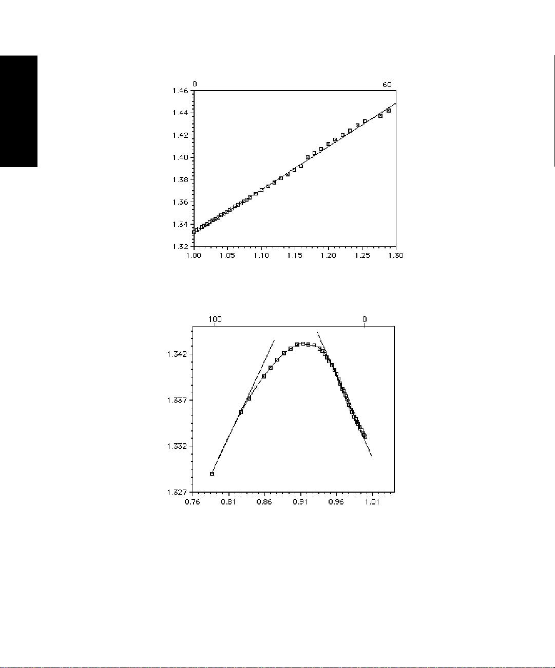
Figure 1-2 illustrates the effect of density on the RI of two solutions. The refractive index of a
sucrose solution changes linearly with concentration over this range of compositions, but a
methanol solution exhibits a nonlinear region between concentrations of 45 and 55 percent.
1
Theory of Operation 1-3
Page 28
1
Weight Percent Sucrose in Water
Refractive Index
Density (g/mL)
Weight Percent Methanol in Water
Refractive Index
Figure 1-2 Effect of Density on RI
1-4 Waters 2410 Theory of Operation
Density (g/mL)
Page 29

Measuring Refraction
The extent to which a beam of light is refracted when it enters a medium depends on two factors:
• The angle at which the light enters the new medium (the
• The refractive indices of the new media
angle of incidence
)
1
The angle of a refracted light beam through the new medium is its
angle of refraction
.
Figure 1-3 illustrates the relationship between angle of incidence, angle of refraction, and refractive
index.
Incoming Light Beam Perpendicular to Surface
Angle of Incidence
Medium 1, RI = n
Medium 2, RI = n
Refracted Light Beam
θ
2
1
2
Angle of Refraction
θ
1
Figure 1-3 Refraction of Light
The relationship between the refractive indices of the two media and the angles of incidence and
refraction is described by Snell’s Law:
n1(sin
θ
where:
θ
= Angle of incidence
1
θ
= Angle of refraction
2
n
= RI of medium 1
1
n
= RI of medium 2
2
) = n2(sin
1
θ
)
2
Theory of Operation 1-5
Page 30

You can use Snell’s Law to calculate the RI of a sample solution from the angle of incidence, the RI
of the solvent, and the angle of refraction.
1
Using Changes in RI for Sample Detection
As the separated components of a sample pass through the refractometer flow cell:
• The composition of the sample solution in the flow cell changes.
• The RI of the solution changes.
• The light beam passing through the solution is refracted.
The refractometer detects the position of the refracted light beam, creating a signal that differs from
the baseline signal.
Figure 1-4 shows how refraction by the sample in the flow cell changes the proportion of light on
each element of the photodiode.
Dual Element
Dual-Element
Photodiode
Photodiode
Collimating
Collimating
Lens
Lens
Sample Side
Sample Side
of Flow Cell
of Flow Cell
Sample in
Sample in
Sample Side
Sample Side
of Flow Cell
of Flow Cell
Reference
Reference Side
of Flow Cell
Side of
Flow Cell
Figure 1-4 Presence of Sample Changes the Photodiode Signal
1-6 Waters 2410 Theory of Operation
Incident Light
Reference Side
of Flow Cell
Reference Side
of Flow Cell
Page 31

By keeping wavelength, temperature, and pressure constant, the changes in RI measured by the
refractometer are due only to changing sample concentration. A solution with a high concentration
of a solute refracts a beam of light more than a dilute solution. Therefore, high concentrations of
sample yield large peaks.
1.2.2 Differential Refractometry
The 2410 differential refractometer can measure extremely small changes in refractive index to
detect the presence of sample. The small difference in RI between a reference solution and a sample
solution is referred to as ∆n. ∆n is expressed in refractive index units (RIU).
The 2410 differential refractometer measures ∆n values as small as 5 × 10⁻⁸ RIU by detecting the
difference in the amount of light falling upon each of the elements of the dual-element photodiode
(see Figure 1-4).
External Angle of Deflection
The amount of light falling upon the elements of the photodiode is determined by the external
angle of deflection (φ), as shown in Figure 1-5. The φ determines the magnitude of the shift (∆x) of
the image cast on the photodiode by the light beam.
Figure 1-5 illustrates the external angle of deflection (φ) and its dependence on the difference in RIs
between the reference and sample sides of the flow cell.
1
Theory of Operation 1-7
Page 32
1
θ
Reference Side
of Flow Cell
θ
n
n
n + ∆n
n
Y
φ
Y
Sample Side
of Flow Cell
φ
= ∆x
Figure 1-5 How Refraction Changes
Effect of Refraction on
As the beam of light moves along the light path to the photodiode, it encounters and is refracted by
the air in the optics bench assembly, the fused quartz walls of the flow cell, the solvent in the
reference side of the flow cell, and the solution in the sample side of the flow cell.
Of these refractors, only the solution in the sample side of the flow cell changes over the course of a
run. As a result, the reference external angle of deflection (φ) does not change until a change in the
RI of the sample causes the light beam to be refracted from its zero position.
1-8 Waters 2410 Theory of Operation
φ
φ
Page 33

The relationship between the external angle of deflection (φ) and the RI of the sample solution is
expressed as:
∆n ≅ φ/tan
where: ∆n =Difference in RI between the solvent and the solvent-sample solution
φ
=External angle of deflection (in radians)
θ
=Angle of incidence (in radians)
θ
Effect of Refraction on the Photodiode Signal
The change in φ determines the shift (∆x) of the light beam on the photodiode. Because the 2410
differential refractometer uses a dual-pass optics bench assembly , the light beam passes through the
flow cell twice before reaching the photodiode, doubling the image shift.
The relationship between the image shift (∆x) at the 2410 detector photodiode and the change in RI
of the solution is expressed as:
∆x = 2Y(tanθ) ∆n
where: ∆x = Distance of the image shift at the photodiode
Y = Distance from the flow cell to the photodiode
θ
=Angle of incidence
∆n =Difference in RI between solvent and sample solution
The angle of incidence (θ) and the distance to the photodiode (Y) are fixed in the refractometer, so
the equation becomes:
1
∆x = C ∆n
Where: C = A constant representing the fixed values
By detecting how far the image shifts (∆x), the refractometer measures the difference in RI (∆n)
between the solvent-sample solution and the solvent alone.
The shift in the amount of the light beam striking each element of the dual-element photodiode
results in a change in the output voltage from the 2410 detector. The integrator or chart recorder
registers the changes in output voltage as peaks in your chromatogram.
1.2.3 Common RI Detection Problems
Changes in solution density caused by factors other than sample concentration are the most
common source of problems in RI detection. Changes in solution density can be due to:
• Environmental factors such as changes in temperature or pressure
• Inhomogeneities in the solution
Theory of Operation 1-9
Page 34

1
Environmental Factors
Even small changes in ambient temperature can cause baseline drift. Backpressure pulses from a
dripping waste tube can cause short-term baseline cycling. Refer to Chapter 7, T roubleshooting, for
more information.
Inhomogeneities in Solution
The differential refractometer measures the difference in refraction between a pure reference
solvent and a homogeneous sample solution within a chromatographic band. If the sample solution
is not homogeneous, the light passing through the sample may be absorbed, scattered, or refracted
unpredictably. This can result in shifts in retention time and broad, tailing peaks. Most common
inhomogeneity problems are due to improper solvent preparation. See Chapter 4, Preparing
Solvents, for more information.
1.3 Principles of Operation
This section describes the design of the 2410 refractometer and its principles of operation,
including:
• Fluidics
• Optics
• Electronics
1.3.1 Fluidics
The fluidic path of the 2410 refractometer includes the following components, some of which are
shown in Figure 1-6:
• Countercurrent heat exchanger
• Flow cell, with sample and reference sides
• Solenoid valve
• Pressure relief valve
• Inlet and outlet tubing
1-10 Waters 2410 Theory of Operation
Page 35

Pressure Relief
Valve
Solenoid
Valve
Outlet T ubing
(Blue)
Inlet Tubing (Red)
TP01532
Figure 1-6 Waters 2410 Refractometer Fluidics
Countercurrent Heat Exchanger
The 2410 refractometer uses a patented countercurrent heat exchanger to minimize temperature
fluctuations in the sample stream. In the countercurrent heat exchanger, the sample and reference
inlet and outlet lines run adjacent to each other. All four lines are copper-coated to facilitate heat
exchange.
1
Flow Cell
The flow cell consists of two fused quartz hollow prisms. Each has an inlet and outlet. One of the
prisms is the sample side of the flow cell through which a constant flow of eluent passes during
analysis.
The other prism is the reference side of the flow cell. It is filled with clean solvent when you purge
the 2410 refractometer during equilibration. When you switch from purge to normal operation, the
solenoid valve opens and the pressure relief valve shuts, stopping the flow of solvent through the
reference prism but leaving the cell filled with solvent.
Principles of Operation 1-11
Page 36

1
Solenoid V alve
During normal operation, the solenoid valve remains open. Fluid that passes through the sample
side of the flow cell flows through the solenoid v alv e and out through the outlet tubing (blue) to the
waste reservoir.
When you purge the 2410 refractometer, the solenoid valve closes, causing fluid passing through
the sample side of the flow cell to flow out through the reference side of the flow cell, through the
purge outlet tubing (blue).
Pressure Relief Valve
During normal operation, the pressure relief valve is closed, opening only if the pressure gets too
high. This protects the flow cell, which has a maximum pressure rating of 100 psi.
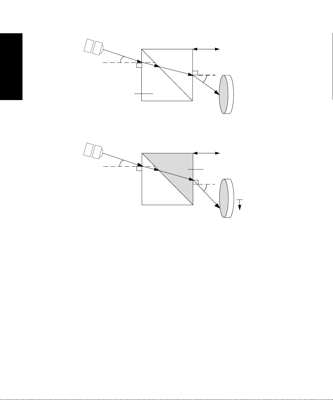
During purging, fluid moving through the sample and reference sides of the flow cell goes out
through the pressure relief valve to the waste reserv oir . Figure 1-7 indicates the paths of solvent and
sample in the 2410 refractometer during normal operation and during a purge. Table 1-1 provides
the inner diameters of the sample and reference fluidic lines.
Table 1-1 luidic Line Inner Diameters
Fluidic Line
Sample In 0.009
Sample Out 0.040
Reference In 0.020
Reference Out 0.040
Inner Diameter
(inches)
1-12 Waters 2410 Theory of Operation
Page 37

Pressure
Relief
Valve
Flow Cell
Reference
Side
T Block
Sample
Side
Solenoid
Heat ExchangerHeat Exchanger
1
Valve
= normal flow path
= purge flow path
Purge Out Out Port In Port
Figure 1-7 Waters 2410 Refractometer Fluidic Paths
from Columnto Waste to Waste
(red) (blue)(blue)
Fluidic Path During Analysis
During analysis, the solvent-sample:
1. Flows in through the inlet tubing port.
2. Passes through the Sample In tube of the countercurrent heat exchanger.
3. Flows through the sample side of the flow cell.
4. Flows out though the Sample Out tube of the countercurrent heat exchanger.
5. Passes through the solenoid valve to the outlet tubing port.
Fluidic Path During Purge
When you purge the 2410 refractometer fluidic path, solvent:
1. Flows in through inlet tubing port.
2. Passes through the Sample In tube of the countercurrent heat exchanger.
Principles of Operation 1-13
Page 38

1
3. Flows through the sample side of the flow cell.
4. Flows out through the Sample Out tube of the countercurrent heat exchanger to the
closed solenoid valve.
5. Passes through the Reference In tube of the countercurrent heat exchanger.
6. Flows through the reference side of the flow cell.
7. Flows out through the Reference Out tube of the countercurrent heat exchanger.
8. Flows out through the pressure relief valve to the purge outlet tubing port.
1.3.2 Optics
The 2410 refractometer optics bench assembly (Figure 1-8) consists of the following components:
• LED source lamp
• LED lens mask
• LED lens
• Flow cell, with sample and reference sides
• Mirror
• Collimating lens
• Dual-element photodiode
Figure 1-8 shows the path of the light beam as it passes through the components in the optics bench
assembly.
As shown in Figure 1-8:
1. Light from the LED is focused by the focusing lens through the aperture and collimating
lens to form a beam.
2. The light beam passes through the sample and reference sides of the flow cell to the
mirror.
3. The light beam is reflected back through both sides of the flow cell and the collimating
lens to the dual-element photodiode.
The difference in the amount of light striking the elements of the photodiode (because of sample
refraction) results in a deflection from the baseline on the chromatogram.
1-14 Waters 2410 Theory of Operation
Page 39

Collimating Lens
LED Lens
Figure 1-8 Waters 2410 Differential Refractometer Optics Bench Assembly Light Path
Dual-Element
Photodiode
LED
Lens
Mask
Flow Cell
MirrorHeat Exchanger CoilsLED
1.3.3 Electronics
1
TP01536
The 2410 refractometer has both analog and digital components, and includes hardware such as the
front panel keyboard and printed circuit (PC) boards and their interconnections. The following PC
boards are included in the 2410 refractometer electronics.
• CPU Board – Provides the interface between the analog input signals from the optics and
the microprocessor, for further signal conditioning. Generates analog output signals, drives
the LED, Auto Zero, and signal compensation electronics, and stores and executes input
from the front panel keypad and the rear panel contact closures. Provides communication
between the 2410 refractometer and external devices through the IEEE-488 interface and
terminal strip input/output connections.
• Front Panel Board – Controls the keypad, indicators, and display.
• Power Distribution Board – Distributes DC voltages to the CPU board, fan, and heaters.
Provides the electronic switching for control of the oven compartment.
Principles of Operation 1-15
Page 40

1
1-16 Waters 2410 Theory of Operation
Page 41

Chapter 2
Installing the 2410
Refractometer
2.1 Introduction....................................................... 2-1
2.2 Site Selection and Power Requirements............ 2-2
2.3 Unpacking and Inspection................................. 2-4
2.4 Making Electrical Power Connections .............. 2-5
2.5 Making Fluidic Connections............................. 2-5
Page 42

Page 43
2
Installing the 2410 Refractometer
This chapter describes the procedures for selecting the site for installing the Waters 2410
Differential Refractometer, unpacking and inspecting the instrument, installing fuses, and making
fluidic connections. For information on connecting the 2410 refractometer to other devices, see
Chapter 3.
2.1 Introduction
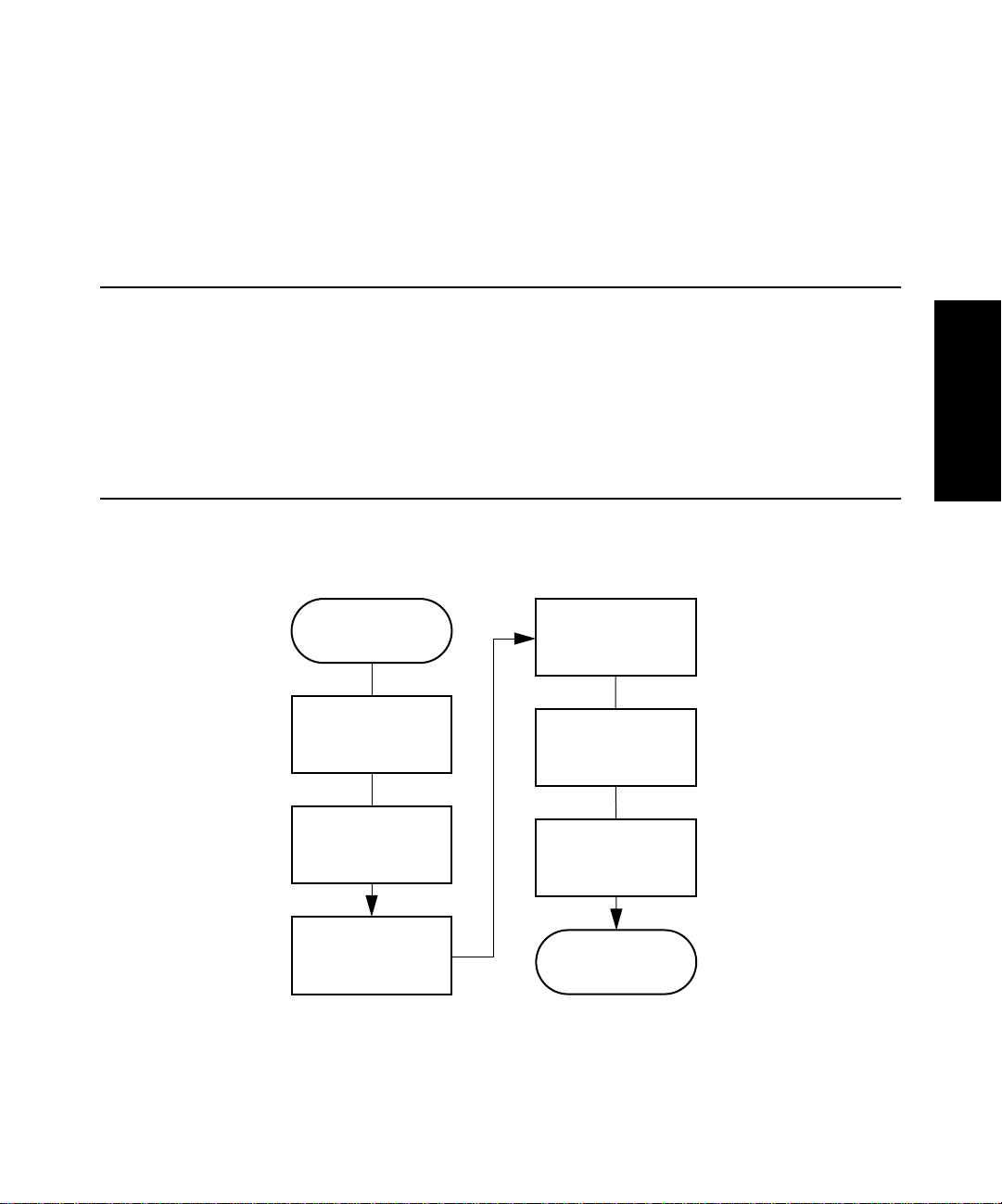
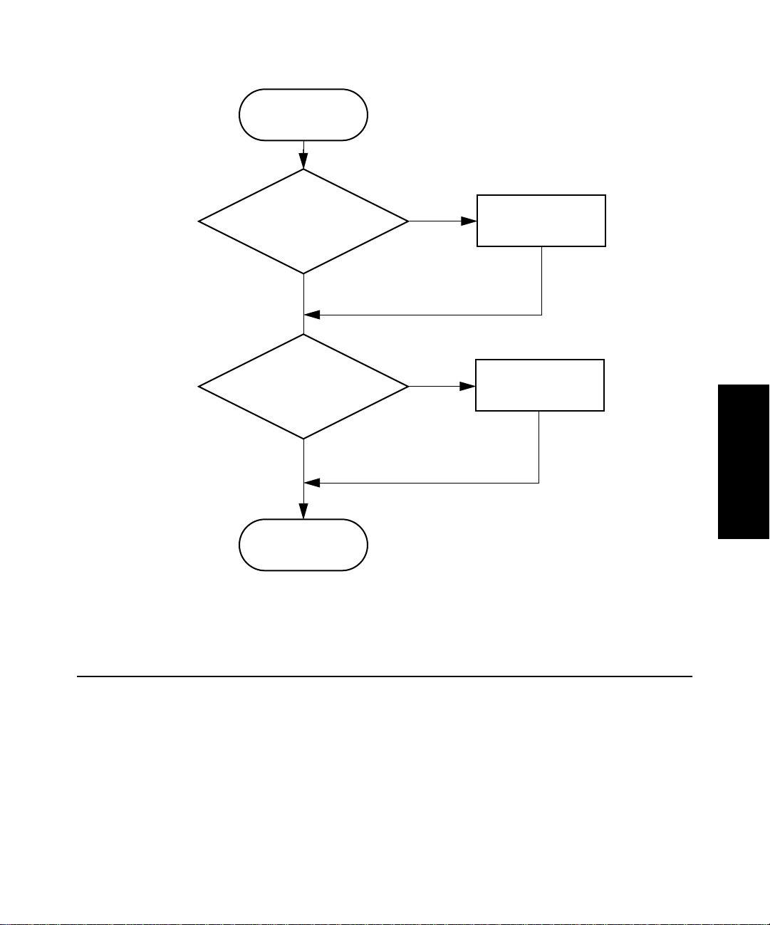
Figure 2-1 shows the major steps in installing the Waters 2410 Differential Refractometer.
2
Start installation
procedure.
Select appropriate
site.
Unpack and
inspect.
Install 2410
refractometer.
Figure 2-1 Major Steps in Installing the 2410 Differential Refractometer
Make power
connections.
Make fluidic
connections.
Make signal
connections to
other devices.
Installation
complete.
Introduction 2-1
Page 44
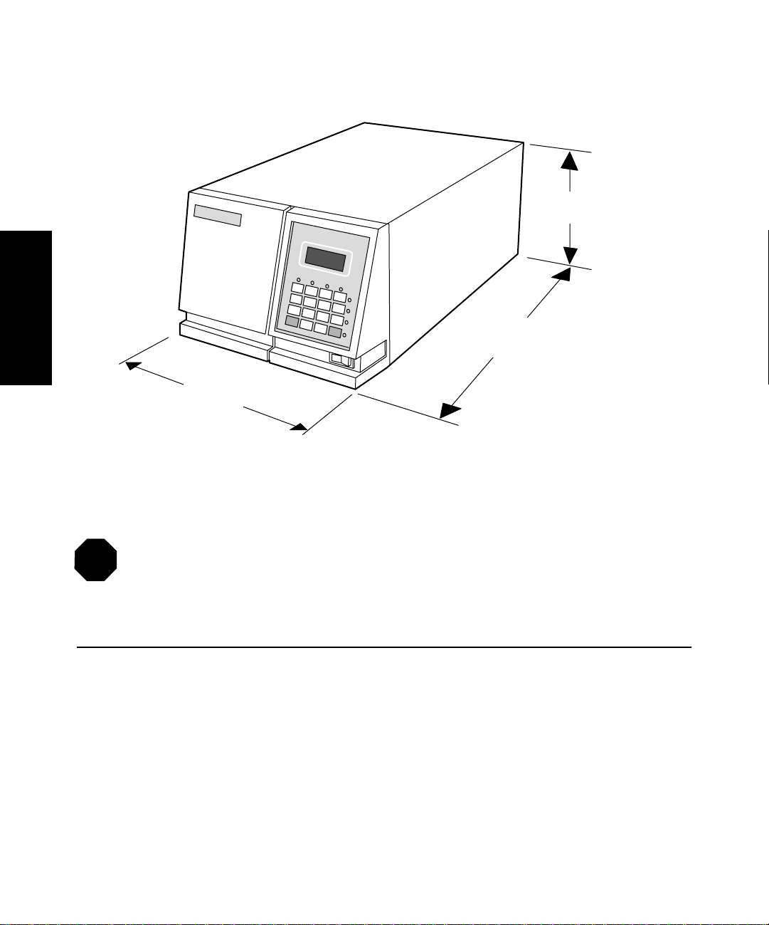
Figure 2-2 shows the dimensions of the 2410 refractometer.
2
STOP
Waters 2410
Differential Refractometer Detector
19.8 inches (50.3 cm)
11.2 inches (28.4 cm)
Figure 2-2 Dimensions of the 2410 Refractometer
Attention: Access to the instrument inside the top cover is not required. All required
access is through the left front panel where the fluidic connections are located (see
Section 2.5, Making Fluidic Connections).
8.2 inches (20.8 cm)
TP01530
2.2 Site Selection and Power Requirements
Reliable operation of your 2410 refractometer depends on a proper installation site and a suitable
power supply.
Site Selection Requirements
Install the Waters 2410 Differential Refractometer in an area that meets the requirements listed in
Table 2-1.
2-2 Installing the 2410 Refractometer
Page 45

Table 2-1 Installation Site Requirements
Parameter Requirement
Operating temperature range +15 °C to +32.2 °C (59 °F to 90 °F); avoid direct
exposure to sunlight and heating/cooling vents.
Storage temperature range –40 °C to 70 °C (–104 °F to 158 °F)
Relative humidity 20% to 80%, noncondensing
Storage humidity range 0% to 90%, noncondensing
Bench space At least 11.2 in. (28.4 cm) wide × 24.8 in. (63 cm)
deep × 8.2 in. (20.8 cm) high (includes 5 in. [12.7
cm] clearance at rear)
Static electricity < 8 kV contact
Power Grounded ac, 100/240 Vac, 50/60 Hz
Surface orientation Level (ensures proper drip tray function)
Power Requirements
2
The 2410 refractometer, which operates over the range 100 Vac to 240 Vac, is shipped from the
factory with two 2.0 A fuses.
Caution: To avoid electrical shock, power off the 2410 refractometer and unplug the
power cord from the rear panel receptacle before you replace a fuse.
Caution: T o reduce the risk of fire hazard, alwa ys replace the fuse with the same type and
rating.
The two fuses are located above the power input receptacle within the power input module on the
rear panel (Figure 2-3).
Site Selection and Power Requirements 2-3
Page 46

Inputs
and Outputs
AB
2
Ext. 2
Ext. 1
Fuse Holder
Figure 2-3 Waters 2410 Refractometer Rear Panel
To replace a fuse in the 2410 refractometer, see Section 6.2, Replacing Fuses.
2.3 Unpacking and Inspection
The Waters 2410 refractometer shipping carton contains:
• Certificate of Structural Validation
• Waters 2410 Differential Refractometer
• Startup Kit
• Waters 2410 Differential Refractometer Operator’s Guide
• Release Notes
IEEE-488
Interface
Connection
Power Input
Receptacle
TP01531
To unpack the 2410 refractometer:
1. Check the contents of the shipping carton against the packing list to ensure you have
received all items.
2. Save the shipping carton for future transport or shipment.
2-4 Installing the 2410 Refractometer
Page 47

If you see any damage or discrepancy when you inspect the contents of the carton, immediately
contact the shipping agent. U.S. and Canadian customers only , also contact W aters T echnical Service
at (800) 252-4752. Other customers, call your local W aters subsidiary or your local W aters T echnical
Service Representative, or call Waters corporate headquarters for assistance at (508) 478-2000 (U.S.).
Note: Make sure the instrument serial number on the rear panel nameplate or inside the
left front panel corresponds to the number on the instrument validation certificate.
For more information about shipments, damages, and claims, see Appendix C, Warranty
Information.
2.4 Making Electrical Power Connections
To connect the 2410 refractometer to the ac power supply:
1. Plug the receptacle end of the power cord into the ac power input receptacle on the rear panel
of the detector (Figure 2-3).
2. Plug the other end of the power cord into a properly grounded ac power source.
For information about the remaining rear panel electrical connections, see Chapter 3, Making
Signal Connections.
2.5 Making Fluidic Connections
Caution: To avoid chemical hazards, always observe good laboratory practices when
handling solvents. Refer to the Material Safety Data Sheets for solvents in use.
This section describes the procedures for connecting the 2410 refractometer to:
• A column or another detector
• A waste container
• The drip tray
2
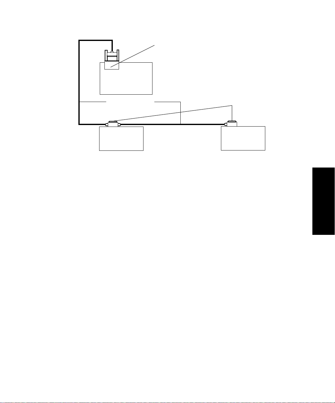
The fluidic connections for the 2410 refractometer are located to the left of the keypad on the front
panel (Figure 2-4).
Making Electrical Power Connections 2-5
Page 48

Pressure Relief
Valve
Solenoid Valv e
2
Outlet Tubing
(blue)
Drip Tray Fitting
(under oven)
Inlet Tubing (red)
Figure 2-4 Fluidic Connections
2.5.1 Connecting a Column or Second Detector
Note: If you are using more than one detector in your system, the W aters 2410 Diff erential
Refractometer must be connected as the last detector in line.
Required Materials
• 1/16-inch stainless steel tubing, 0.009-inch ID (from Startup kit)
• Waters 1/16-inch stainless steel tubing cutter or file
• Pliers, cloth-covered
• Two compression fittings and ferrules (from Startup kit)
• 5/16-inch open-end wrench
TP01532
To connect a column or other detector to the 2410 refractometer:
1. Measure the minimum length of tubing needed to connect the column or other detector
outlet to the inlet tubing port.
2-6 Installing the 2410 Refractometer
Page 49

2. Cut the tubing to the required length.
a. Use the stainless steel tubing cutter or a file with a cutting edge to scribe the
circumference of the tubing at the desired end point.
b. Grasp the tubing on both sides of the scribed mark with cloth-covered pliers (to prevent
marring the surface) and gently work the tubing back and forth until it separates.
c. File the ends smooth and straight for maximum column efficiency, and remove all
burrs.
3. Slide a compression screw and ferrule over one end of the tubing, as shown in
Figure 2-5.
Compression
Screw
Tube
Distance (determined by
TP01139
Figure 2-5 Ferrule and Compression Screw Assembly
4. Bottom the tubing in the inlet tubing port fitting of the refractometer, then seat the
ferrule by tightening the compression screw 3/4-turn past finger-tight with the 5/16-inch
open-end wrench.
5. Repeat steps 3 and 4 to connect the tubing to the outlet fitting of the column or another
detector.
each application, such as
union or column fitting)
2.5.2 Connecting to Waste
Because the 2410 refractometer flow cell is very sensitive to backpressure, be sure to use waste
tubing that is 0.040-inch ID and that is no more than 18 to 24 inches (45 to 60 cm) long.
Ferrule
2
Tubing End (straight and
smooth to achieve maximum
column efficiency)
Required Materials
• 1/16-inch stainless steel tubing, 0.040-inch ID (from Startup kit)
• Waters 1/16-inch stainless steel tubing cutter or file
• One compression fitting and ferrule (from Startup kit)
Making Fluidic Connections 2-7
Page 50

2
• 5/16-inch open-end wrench
• Waste container
To connect the 2410 refractometer to waste:
1. Cut the minimum length of tubing needed, as described in Section 2.5.1, Connecting a
Column or Second Detector.
2. Slide the compression fitting and ferrule over one end of the 0.040-inch tubing, as
shown in Figure 2-5.
3. Bottom the tubing in the outlet tubing port fitting of the refractometer, then seat the
ferrule by tightening the compression screw 3/4-turn past finger-tight with the 5/16-inch
open-end wrench.
4. Place the waste container lower than, or at the same level as, the 2410 refractometer.
5. Place the free end of the tubing in the waste container.
STOP
Attention: The maximum pressure for the 2410 refractometer flow cell is 100 psi. The
flow cell could be damaged if this pressure is exceeded.
2.5.3 Connecting to a Drip Tray
The 2410 refractometer contains a drip tray underneath the flow cell behind the front panel to direct
solvent leaks to the front of the unit.
Connecting the drip tray is usually unnecessary, but, if you connect it, be sure to position the waste
container below the drip tray outlet.
Required Materials
• PTFE tubing, 0.063-inch ID (from the Startup kit)
• Razor blade
To connect the drip tray:
1. Cut a length of PTFE tubing sufficient to reach between the drip tray and the waste
container.
2. Connect the tubing to the white plastic fitting located under the oven of the 2410
refractometer (see Figure 2-4).
3. Insert the other end of the tubing into the waste container.
2-8 Installing the 2410 Refractometer
Page 51

Chapter 3
Making Signal
Connections
3.1 Component Connection Overview .................... 3-1
3.2 Making IEEE-488 Signal Connections ............. 3-3
3.3 Making Non-IEEE-488 Signal Connections..... 3-8
3.4 Connecting the External Column Heaters....... 3-19
Page 52

Page 53

3
Making Signal Connections
This chapter describes procedures for making signal connections between the Waters 2410
Differential Refractometer and other HPLC system components.
3.1 Component Connection Overview
Table 3-1 summarizes the signal connections needed to connect the 2410 refractometer to other
HPLC system components.
Table 3-1 Component Connection Summary
Connector Type Component
IEEE-488 Connections
IEEE-488 Connector • Millennium Chromatography Manager
through the busLAC/E card
• Waters 845/860 Data System through
the LAC/E or busSAT/IN Module
• Waters PowerLine™ System Controller
• Waters 2690 Separations Module
Non-IEEE-488 Connections
Analog outputs • 745/745B/746 Data Module (integrator
or data system using the A/D interface)
• Chart recorder
• Compressed data output
Event inputs • System controller (used with the Waters
2690 Separations Module and the 600
Series solvent delivery system)
• Waters 700 series or a non-Waters
autosampler
• Waters or non-Waters manual injector
9-Pin DIN • Waters or non-Waters manual injector
• Two optional external column heaters
3
Component Connection Overview 3-1
Page 54

Figure 3-1 shows the rear panel locations of the connectors used to operate the 2410 refractometer
with external devices.
AB
Analog-Out
and Event-In
Connectors
3
9-Pin DIN
Connectors (for
External Column
Heaters)
Fuse Holder
IEEE-488 Interface
Power Input
Figure 3-1 Waters 2410 Differential Refractometer Rear Panel
The signal connections you need to make to your 2410 refractometer depend on the signal
connections available on the other instruments in your HPLC system.
Figure 3-2 provides an overview of the steps to follow to connect the 2410 refractometer to other
instruments in your HPLC system.
TP01531
3-2 Making Signal Connections
Page 55
Start Signal
Connection Procedure
Connect to
IEEE-488
Bus?
No
No
Connect
to Non-IEEE
Instrument, Such as Integrator,
Chart Recorder,
bus SAT/IN,
etc.
No
Signal Connections
Complete
Yes
Yes
Install IEEE-488
Cable
Install Event and I/O
Cable(s)
Figure 3-2 Overview of Connecting Components to the 2410 Differential Refractometer
3
3.2 Making IEEE-488 Signal Connections
You can use the IEEE-488 bus to connect the 2410 refractometer to Waters or third-party data
systems.
3.2.1 Connecting to a Waters Data System Using the IEEE-488 Bus
You can use the IEEE-488 bus to connect the 2410 refractometer to a W aters data system in an y one
of the following configurations (see Figure 3-3, Figure 3-4, and Figure 3-5):
• Millennium Chromatography Manager through the busLAC/E™ card installed on the
computer (Figure 3-3)
Making IEEE-488 Signal Connections 3-3
Page 56

3
• Waters 845 or 860 system through a LAC/E module (Figure 3-4)
• Waters 2690 Separations Module as part of an Alliance system (Figure 3-5).
Bus LAC/E or Network LAC/E Card
Millennium
Chromatography
Manager
IEEE-488 Cables
IEEE-488
Connector
600 Series
Pump
717plus
Autosampler
2410
Refractometer
Figure 3-3 Waters Millennium System IEEE-488 Connections
IEEE-488 Connector
IEEE-488
Cable
IEEE-802.3
Ethernet Connector
Thin Wire
Ethernet Cable
600 Series
Pump
IEEE-488
Cables
717plus
Autosampler
Figure 3-4 Waters 845/860 System IEEE-488 Connections
3-4 Making Signal Connections
LAC/E Module
ExpertEase 845/860
Workstation
2410
Refractometer
Page 57
Millennium
Chromatography
Manager
Bus LAC/E or Network LAC/E Card
IEEE-488 Cables
2690
Separations
Module
Figure 3-5 Waters Alliance System IEEE-488 Connections
IEEE-488 Connectors
2410
Refractometer
Setting the IEEE-488 Address
Like all other IEEE-488 devices, the 2410 refractometer requires a unique IEEE-488 address to be
recognized by an IEEE-488 controller, such as a Millennium Chromatography Manager , b usLA C/E
module, or an Alliance™ or PowerLine™ System Controller.
The factory-set default IEEE-488 address for the 2410 differential refractometer is 10. To change
the IEEE-488 address:
1. Press 2nd Func, Clear, Clear, then press Enter. The value diag is displayed.
2. Press 2nd Func, 6, Enter.
3. Enter the number corresponding to the desired IEEE-488 address, then press Enter.
Note: IEEE-488 addresses must be unique for each instrument in an HPLC system and
must be between 2 and 29. Your HPLC system may require that the IEEE-488 address for
the 2410 refractometer be greater than that for other devices in the system. Consult your
data system or controller operator's manual for more information on IEEE-488
communications.
3
4. To exit the diagnostic functions, press 2nd Func, Clear, then press Enter.
Making Inject Start Signal Connections
When you are using an IEEE-488 data system with the 2410 differential refractometer, the data
system or controller must receive an inject start signal from the autosampler or manual injector to
initiate the data collection and time-based programs.
Making IEEE-488 Signal Connections 3-5
Page 58

Note: Depending on your system configuration, the inject start signal can be transmitted
through the IEEE-488 interface or the analog-out/event-in connectors on the 2410
refractometer rear panel. For information on non-IEEE-488 connections, see Section 3.3,
Making Non-IEEE-488 Signal Connections.
Table 3-2 summarizes the inject start connections for different system configurations.
Note: If multiple devices in your system require an inject start signal, connect trigger wires
from the same (inject out) terminal on the injector to each device.
Table 3-2 Waters 2410 Refractometer Inject Start Connections
3
Inject Start Output Source
Waters 715, 717, and 717plus,
and 2690 Separations Module, on
the IEEE-488 bus
W aters 715, 717, and 717plus not
on the IEEE-488 bus
W aters 2690 Separations Module
not on the IEEE-488 bus
Waters 712 Autosampler Chart Mark and Ground
Waters manual injector, or
third-party manual injector or
autosampler
IEEE-488 interface (see Section 3.2.1, Connecting to a
Waters Data System Using the IEEE-488 Bus)
Note: If you are using the Waters 845 or 860 Data
System, you must program the multi-method to Start
By LAC/E (refer to the ExpertEase Reference Guide
for details).
Chart Mark and Ground
Chart Mark and Ground or Auto Zero and Ground
Chart Mark and Ground
Inject Start Input Connection
(on the 2410 Refractometer)
3-6 Making Signal Connections
Page 59
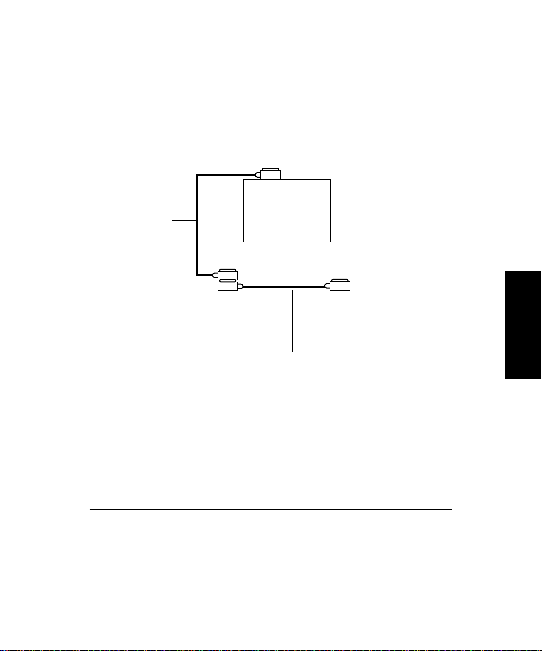
3.2.2 Connecting to a Waters PowerLine System Controller
To connect the 2410 refractometer to a Waters PowerLine system controller, use the IEEE-488
interface cables as shown in Figure 3-6.
Each fluid-handling unit is configured with either of the following:
• Integrated manual injector (built in as part of the drawer or shelf unit)
• Externally connected manual injector or autosampler
PowerLine
Controller
(600 Series Solvent
IEEE-488
Cable
Delivery System or
2690 Separations
Module)
717plus
Autosampler
Figure 3-6 Waters PowerLine System Controller IEEE-488 Connections
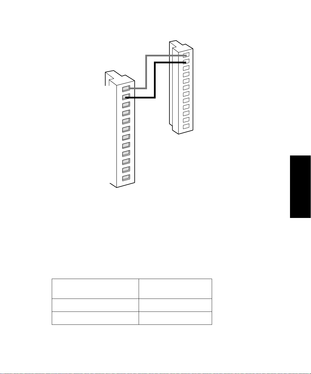
3.2.3 Connecting to a Manual Injector
If you are using a manual injector with your IEEE-488 system, connect the signal cables from the
rear panel connector on the 2410 refractometer to the injector as indicated in Table 3-3.
Table 3-3 Waters 2410 Connections to a Manual Injector
2410 Refractometer
(Connector B)
Chart Mark + (red) One set of spade lug Chart Mark terminals
(the Waters injector includes two pairs of
Chart Mark – (black)
For information on injection trigger signals from a manual injector, see Section 3.3.5, Connecting
Injection Trigger Signals.
cables that are functionally identical)
2410
Refractometer
Manual Injector
3
Making IEEE-488 Signal Connections 3-7
Page 60

3
3.3 Making Non-IEEE-488 Signal Connections
To connect the 2410 refractometer to instruments that lack an IEEE-488 bus, you use the
analog-out/event-in (I/O) connectors on the rear panel (Figure 3-7). Figure 3-7 shows the two I/O
connectors (and their corresponding pin-outs) on the 2410 refractometer rear panel. Table 3-4
describes the functions of each connector.
This section describes signal connections between the 2410 refractometer rear panel
analog-out/event-in connectors and the following:
• Waters 2690 Separations Module (used independently of the IEEE-488 interface)
• Waters 745/745B/746 Integrator
• Chart recorder
• Waters SAT/IN module
• Waters or other manual injector
• Other manufacturer’s integrator or A/D interface device
Caution: To avoid electrical shock, power off the 2410 refractometer before making any
electrical connections.
Attention: To meet the regulatory requirements of immunity from external electrical
STOP
disturbances that may affect the performance of this instrument, do not use cables longer
than 9.8 feet (3 meters) when you make connections to the analog-out/event-in
connectors. In addition, ensure you always connect the shield of the cable to ground at
one instrument only.
3-8 Making Signal Connections
Page 61

A (Inputs and Outputs)
B (Inputs and Outputs)
1 Auto Zero +
2 Auto Zero –
3 Chassis Ground
4 Purge In +
5 Purge In –
6 Chassis Ground
7 Recorder Out +
8 Recorder Out –
9 Chassis Ground
10 Compressed Out +
11 Compressed Out –
12 Chassis Ground
1 Chart Mark +
2 Chart Mark –
3 Chassis Ground
4 Polarity 1 +
5 Polarity 1 –
6 Chassis Ground
7 Polarity 2 +
8 Polarity 2 –
9 Chassis Ground
10 Integrator Out +
11 Integrator Out –
12 Chassis Ground
Figure 3-7 Waters 2410 Rear Panel Analog-Out/Event-In Connectors
Table 3-4 describes the functions of the 2410 refractometer analog-out/event-in connectors.
Table 3-4 Waters 2410 Analog-Out/Event-In Connections
3
Signal Connections Description
Chart Mark
Polarity 1 and 2
Accept TTL-level (0 to +5 V) or contact closure
signals from an external instrument
Auto Zero
Purge
Recorder Out Sends a ±2 V (full scale) signal to a chart recorder
Integrator Out Sends a ±2 V (full scale) signal to an integrator or
computer
Compressed Out Sends a compressed (logarithmic) 0 to +10 mV
maximum output signal to a chart recorder or
integrator
Making Non-IEEE-488 Signal Connections 3-9
Page 62

3
3.3.1 Connecting to a Stand-Alone 2690 Separations Module
Note: When you use the 2690 Separations Module as the system controller on the
IEEE-488 bus, follow the instructions for connecting to a Waters PowerLine system
(see Section 3.2.2, Connecting to a Waters PowerLine System Controller).
When you use the 2690 Separations Module as a stand-alone controller (not on the IEEE-488 bus
or under Millennium software control), you can make the following signal connections using the
2410 refractometer analog-out/event-in connectors:
• Auto zero on inject
• Chart mark on inject
• Both chart mark and auto zero on inject
Generating Auto Zero on Inject
To generate the auto zero function on the 2410 refractometer at the start of an injection from the
2690 Separations Module, make the connections shown in Table 3-5 and Figure 3-8.
Table 3-5 Auto Zero Connections Between the 2690 Separations Module
and the 2410 Refractometer
2690 Separations Module
(Connector B)
Pin 1 Inject Start Pin 1 Auto Zero +
Pin 2 Inject Start Pin 2 Auto Zero –
3-10 Making Signal Connections
2410 Refractometer
(Connector A)
Page 63
Waters 2410 Refractometer
Connector A
Waters 2690
Connector B
Inject Start
Inject Start
Ground
Stop Flow+
Stop Flow–
Hold Inject 1+
Hold Inject 1–
Hold Inject 2+
Hold Inject 2–
Ground
Chart Out+
Chart Out–
Red
Black
1
2
3
4
5
6
7
8
9
10
11
12
1 Auto Zero+
2 Auto Zero–
3 Chassis Ground
4 Purge In+
5 Purge In–
6 Chassis Ground
7 Recorder Out+
8 Recorder Out–
9 Chassis Ground
10 Compressed Out+
11 Compressed Out–
12 Chassis Ground
TP01527
Figure 3-8 Auto Zero Connections Between the 2690 Separations Module
and the 2410 Refractometer
3
Generating Chart Mark on Inject
To generate the chart mark function on the 2410 refractometer at the start of an injection from the
2690 Separations Module, make the connections shown in Table 3-6 and Figure 3-9.
Table 3-6 Chart Mark Connections Between the 2690 Separations Module and the
2410 Refractometer
2690 Separations Module
(Connector B)
Pin 1 Inject Start Pin 1 Chart Mark +
Pin 2 Inject Start Pin 2 Chart Mark –
2410 Refractometer
(Connector B)
Making Non-IEEE-488 Signal Connections 3-11
Page 64

Waters 2410 Refractometer
Connector B
3
Waters 2690
Connector B
Inject Start
Inject Start
Ground
Stop Flow+
Stop Flow–
Hold Inject 1+
Hold Inject 1–
Hold Inject 2+
Hold Inject 2–
Ground
Chart Out+
Chart Out–
10
11
12
Red
1
2
3
4
5
6
7
8
9
Black
1 Chart Mark+
2 Chart Mark–
3 Chassis Ground
4 Polarity 1+
5 Polarity 1–
6 Chassis Ground
7 Polarity 2+
8 Polarity 2–
9 Chassis Ground
10 Integrator Out+
11 Integrator Out–
12 Chassis Ground
TP01527
Figure 3-9 Chart Mark Connections Between the 2690 Separations Module
and the 2410 Refractometer
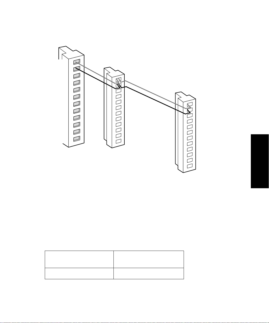
Generating Chart Mark and Auto Zero
To generate both a chart mark and an auto zero signal from the 2690 Separations Module to the
2410 refractometer, make the connections shown in Table 3-7 and Figure 3-10.
Table 3-7 Chart Mark and Auto Zero Connections Between the 2690 Separations Module
and the 2410 Refractometer
2690 Separations
Module
(Connector B)
Pin 1 Inject Start Pin 1 Auto Zero + Pin 1 Chart Mark +
Pin 2 Inject Start Pin 2 Auto Zero – Pin 2 Chart Mark –
3-12 Making Signal Connections
2410 Refractometer
(Connector A)
2410 Refractometer
(Connector B)
Page 65
Waters 2690
Connector B
Inject Start
Inject Start
Ground
Stop Flow+
Stop Flow–
Hold Inject 1+
Hold Inject 1–
Hold Inject 2+
Hold Inject 2–
Ground
Chart Out+
Chart Out–
10
11
12
Waters 2410 Refractometer
1
2
3
4
5
6
7
8
9
Red
Black
Connector A
1 Auto Zero+
2 Auto Zero–
3 Chassis Ground
4 Purge In+
5 Purge In–
6 Chassis Ground
7 Recorder Out+
8 Recorder Out–
9 Chassis Ground
10 Compressed Out+
11 Compressed Out –
12 Chassis Ground
Waters 2410 Refractometer
Connector B
Figure 3-10 Chart Mark and Auto Zero Connections Between
the 2690 Separations Module and the 2410 Refractometer
1 Chart Mark+
2 Chart Mark–
3 Chassis Ground
4 Polarity 1+
5 Polarity 1–
6 Chassis Ground
7 Polarity 2+
8 Polarity 2–
9 Chassis Ground
10 Integrator Out+
11 Integrator Out–
12 Chassis Ground
TP01527B
3
3.3.2 Connecting to the Waters 745/745B/746 Data Module
To send an integrator analog output signal (–2V to +2V) from the 2410 refractometer to the
Waters 745/745B/746 Data Module, make the connections shown in Table 3-8 and Figure 3-11.
Table 3-8 Analog Output Connections to a 745/745B/746 Data Module
745/745B/746 Rear Panel
Connectors
CHA (+) Pin 10 Integrator Out+ (red)
2410 Refractometer
(Connector B)
Making Non-IEEE-488 Signal Connections 3-13
Page 66

Table 3-8 Analog Output Connections to a 745/745B/746 Data Module (Continued)
3
745/745B/746 Rear Panel
Connectors
2410 Refractometer
(Connector B)
CHA (–) Pin 11 Integrator Out– (black)
Shield not used; tape back to prevent shorting.
Note: If you use the Waters 745/745B/746 with a chart recorder, use separate channels
for plotting and integration. Otherwise, changes in chart recorder attenuation may affect
the integration of the peaks.
Note: If you use another manufacturer’s integrator or A/D device, you may need to
connect the Chassis Ground (pin 12) to the 2410 detector’s Integr ator Out– (blac k lead) or
an equivalent connection.
Waters 2410 Refractometer
Connector B
Red
Black
+ –
CHA
Waters 745/745B/746
Connector or Other
A/D Interface Device
1 Chart Mark+
2 Chart Mark–
3 Chassis Ground
4 Polarity 1+
5 Polarity 1–
6 Chassis Ground
7 Polarity 2+
8 Polarity 2–
9 Chassis Ground
10 Integrator Out+
11 Integrator Out–
12 Chassis Ground
Figure 3-11 Connections to a Waters 745/745B/746 Data Module
3-14 Making Signal Connections
TP01486
Page 67
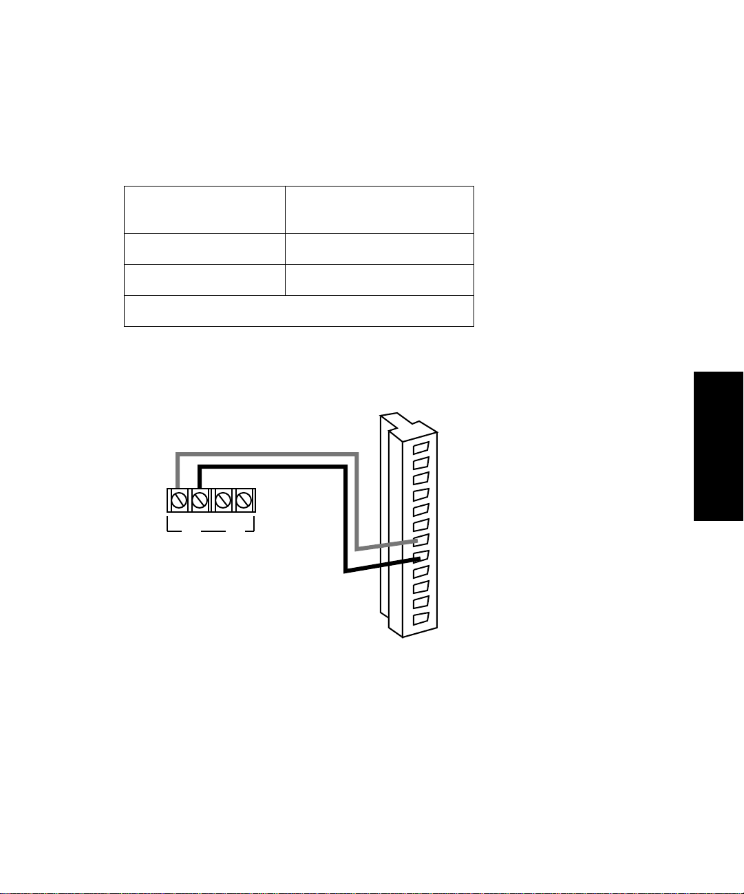
3.3.3 Connecting to a Chart Recorder
To send an analog output signal from the 2410 refractometer to a chart recorder, make the
connections shown in Table 3-9 and Figure 3-12.
Table 3-9 Analog Output Connections to a Chart Recorder
Chart Recorder
Connectors
2410 Refractometer
(Connector A)
Pen 1 (+) Pin 7 Recorder Out + (red)
Pen 1 (–) Pin 8 Recorder Out – (black)
Shield not used; tape back to prevent shorting.
Waters 2410 Refractometer
Connector A
Red
Black
Y1
+
Y2
+ – –
Chart Recorder
Connectors
Auto Zero +
1
Auto Zero –
2
Chassis Gnd
3
Purge In +
4
5
Purge In –
Chassis Gnd
6
Recorder Out +
7
8
Recorder Out –
9
Chassis Gnd
10
Compressed Out +
11
Compressed Out –
12
Chassis Gnd
3
TP01488
Figure 3-12 Analog Output Connections to a Chart Recorder
Performing Chart Mark with the Chart Recorder
If you are controlling the 2410 refractometer from the 745/745B/746 data module and you want to
send a chart mark pulse to the chart recorder at the start of each run, connect the external device
(system controller, autosampler, or manual injector) to the 2410 refractometer Chart Mark screw
terminals, as described in Section 3.3.2, Connecting to the Waters 745/745B/746 Data Module.
Making Non-IEEE-488 Signal Connections 3-15
Page 68

3.3.4 Connecting to the Waters 845/860 ExpertEase System
T o send an inte grator analog output signal (–2V to +2V) from the 2410 refractometer to an 845/860
ExpertEase System (through a two-channel SAT/IN module), make the connections shown in
Table 3-10 and Figure 3-13.
Table 3-10 Analog Output Connections to the Bus SAT/IN Module
3
SAT/IN Module
Connector
CHANNEL 1 or
CHANNEL 2
2410 Refractometer
(Connector B)
Pin 10 Integrator Out + (white)
Pin 11 Integrator Out – (black)
See Section 3.2.1, Connecting to a Waters Data System Using the IEEE-488 Bus, Figure 3-4, for
information on connecting the remaining components of the 845/860 Data System.
Waters 2410 Refractometer
Connector B (Inputs and Outputs)
1 Chart Mark +
1
2
2 Chart Mark –
3
3 Chassis Gnd
4
4 Polarity 1 +
5
5 Polarity 1 –
6
Waters Bus SAT/IN Module
CHANNEL 1 CHANNEL 2
EVENTS
CH1
CH2
IN INOUT OUT
+ – + – + – + –
1 2 3 4 5 6 7 8
CH1CH
Red
White
2
Black
6 Chassis Gnd
7
7 Polarity 2 +
8
8 Polarity 2 –
9
9 Chassis Gnd
10
10 Int Out +
11
11 Int Out –
12
12 Chassis Gnd
TP01484
Figure 3-13 Analog Output Connections to the Bus SAT/IN Module
3.3.5 Connecting Injection Trigger Signals
The 2410 refractometer accepts the following injection trigger signals from a manual injector:
• Auto zero signal to automatically adjust the zero offset of the 2410 refractometer each time
the injector makes an injection
• Chart mark (inject start) signal from a contact closure signal with each injection
3-16 Making Signal Connections
Page 69

Each time the 2410 refractometer receives a signal from a manual injector, it performs the
corresponding auto zero or chart mark function.
To send an auto zero or chart mark signal from a manual injector to the 2410 refractometer, make
the connections shown in Table 3-11 and Figure 3-14 and Table 3-12 and Figure 3-15.
Table 3-11 Auto Zero Connections to a Manual Injector
2410 Refractometer
(Connector A)
Manual Injector Connector
Pin 1, Auto Zero + (red) Two spade lug terminal connectors
(both cables may be functionally
Pin 2, Auto Zero – (black)
Waters 2410 Refractometer
Connector A
1 Auto Zero +
2 Auto Zero –
3 Chassis Ground
4 Purge In +
5 Purge In –
6 Chassis Ground
7 Recorder Out +
8 Recorder Out –
9 Chassis Ground
10 Compressed Out +
11 Compressed Out –
12 Chassis Ground
identical) or similar connectors.
Manual
Injector
3
Figure 3-14 Auto Zero Connectionto a Manual Injector
Making Non-IEEE-488 Signal Connections 3-17
Page 70
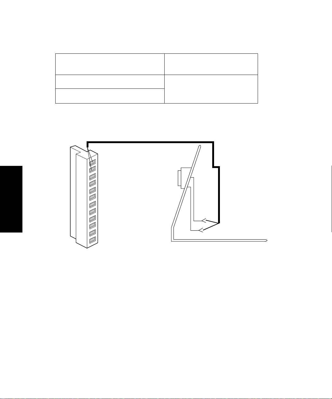
Table 3-12 Chart Mark Connections to a Manual Injector
3
2410 Refractometer
(Connector B)
Manual Injector Connector
Pin 1, Chart Mark + (red) Two spade lug terminal connectors
(both cables may be functionally
Pin 2, Chart Mark – (black)
Waters 2410 Refractometer
Connector B
1 Chart Mark+
2 Chart Mark–
3 Chassis Ground
4 Polarity 1+
5 Polarity 1–
6 Chassis Ground
7 Polarity 2+
8 Polarity 2–
9 Chassis Ground
10 Integrator Out+
11 Integrator Out–
12 Chassis Ground
identical) or similar connectors.
Manual
Injector
Figure 3-15 Chart Mark Connections to a Manual Injector
3.3.6 Polarity Connections
The Polarity 1 and 2 contact closures on the rear panel of the 2410 refractometer determine the
peak polarity of the output signal according to the following conditions (negati v e polarity results in
negative, or inverted, peaks):
• Polarity 1 serves as a positive/negative input
• Polarity 2 serves as an external input (Polarity 1) enable
• When Polarity 2 is open (not connected), the +/– key on the 2410 front panel or an IEEE-488
connected data system (such as the Millennium Chromatography Manager or PowerLine)
determines the polarity (see Section 5.2.5, Polarity Guidelines).
3-18 Making Signal Connections
Page 71

• When Polarity 2 is closed (connected to an instrument), Polarity 1 determines peak polarity.
Polarity 1 open (disconnected) generates negative polarity. Polarity 1 closed (connected)
generates positive polarity.
Table 3-13 summarizes the polarity options.
Table 3-13 Polarity Options
Polarity 2 Polarity 1 Recorder Polarity
Open Open No Effect
Open Closed No Effect
Closed Open Negative (Inverted)
Closed Closed Unchanged
3.4 Connecting the External Column Heaters
The W aters 2410 Dif ferential Refractometer can control up to two optional e xternal column heaters
through the EXT 1 and EXT 2 ports l on the rear panel of the detector (Figure 3-16). The ports are
standard 9-pin DIN connectors.
3
Connecting the External Column Heaters 3-19
Page 72

Waters 2410 Refractometer
Rear Panel
External
Column
Heater
Ports
AB
EXT 2 EXT 1
3
Figure 3-16 2410 Refractometer External Column Heater Ports
3-20 Making Signal Connections
Page 73

Chapter 4
Preparing Solvents
4.1 Common Solvent Problems............................... 4-1
4.2 Selecting a Solvent ............................................ 4-2
4.3 Solvent Degassing ............................................. 4-4
Page 74

Page 75

4
Preparing Solvents
Proper solvent selection and preparation are critical in differential refractometry to prev ent baseline
changes such as drift, noise, or an erratic baseline. This chapter presents information on:
• Common solvent problems
• Selecting a solvent
• Solvent degassing
Caution: To avoid chemical hazards, always observe good laboratory practices when
handling solvents. Refer to the Material Safety Data Sheets shipped with solvents for
handling information.
4.1 Common Solvent Problems
The 2410 refractometer measures changes in the concentration of the solution flowing through the
sample side of the flow cell (see Section 1.2, Theory of Operation). Howe v er, factors other than the
presence of dissolved sample molecules can affect a solution’s refractive index. Common problems
include:
• Changes in temperature
• Changes in pressure
• Contaminants
• Separation of mixed solvents
• Outgassing of dissolved gases
4
Common Solvent Problems 4-1
Page 76

4.2 Selecting a Solvent
An ideal solvent for your analysis:
• Has good solubility characteristics for your application
• Has a significantly different refractive index (RI) than the sample components
• Gives satisfactory baseline noise performance
• Provides optimum optical sensitivity characteristics
Solvent Quality
Use spectral-grade or HPLC-grade solvents to ensure:
• Reproducible results
• Operation with minimal instrument maintenance
• Minimal optical interference
A dirty or impure solvent can cause:
• Baseline noise and drift
• Plugged columns
• Blockages in the fluidic path
Preparation Checklist
4
The following solvent preparation guidelines help to ensure stable baselines and good resolution:
• Filter solvents with a 0.45-µm filter.
• Degas and/or sparge the solvent.
• Stir the solvent.
• Keep solvents in a place free from drafts and shock.
Water
Use water only from a high-quality water purification system. If the water system does not provide
filtered water, filter it through a 0.45-µm membrane filter before use.
Buffers
When you use buffers, dissolve salts first, adjust the pH, then filter to remove undissolved material.
4-2 Preparing Solvents
Page 77
Tetrahydrofuran (THF)
When you use unstabilized THF, ensure that your solvent is fresh. Previously opened bottles of
THF contain peroxide contaminants, which cause baseline drift.
Caution: THF contaminants (peroxides) are potentially explosive if concentrated or taken
to dryness.
Refractive Indices of Common Solvents
Table 4-1 lists the refractive indices for some common chromatographic solvents. Use this table to
verify that the solvent you intend to use for your analysis has an RI significantly different from the
sample components.
Table 4-1 Refractive Indices of Common Solvents
Solvent RI Solvent RI
Fluoroalkanes 1.25 Tetrahydrofuran (THF) 1.408
Hexafluoroisopropanol (HFIP) 1.2752 Amyl alcohol 1.410
Methanol 1.329 Diisobutylene 1.411
Water 1.33 n-Decane 1.412
Acetonitrile 1.344 Amyl chloride 1.413
Ethyl ether 1.353 Dioxane 1.422
n-Pentane 1.358 Ethyl bromide 1.424
Acetone 1.359 Methylene chloride 1.424
Ethanol 1.361 Cyclohexane 1.427
Methyl acetate 1.362 Ethylene glycol 1.427
Isopropyl ether 1.368 N,N-dimethyl formamide
(DMF)
Ethyl acetate 1.370 N,N-dimethyl acetamide
(DMAC)
1-Pentene 1.371 Ethyl sulfide 1.442
Selecting a Solvent 4-3
1.428
1.438
4
Page 78

Table 4-1 Refractive Indices of Common Solvents (Continued)
Solvent RI Solvent RI
Acetic acid 1.372 Chloroform 1.443
Isopropyl chloride 1.378 Ethylene dichloride 1.445
Isopropanol 1.38 Carbon tetrachloride 1.466
n-Propanol 1.38 Dimethyl sulfoxide (DMSO) 1.477
Methylethylketone 1.381 Toluene 1.496
Diethyl amine 1.387 Xylene ~1.50
n-Propyl chloride 1.389 Benzene 1.501
Methylisobutylketone 1.394 Pyridine 1.510
Nitromethane 1.394 Chlorobenzene 1.525
1-Nitropropane 1.400 o-Chlorophenol 1.547
Isooctane 1.404 Aniline 1.586
4
Cyclopentane 1.406 Carbon disulfide 1.626
4.3 Solvent Degassing
Using degassed solvents is the most important step in solvent preparation. Degassing provides:
• Stable baselines and enhanced sensitivity
• Reproducible retention times
• Stable pump or solvent delivery system operation
This section presents information on the solubility of gases, solvent degassing methods, and solvent
degassing considerations.
4-4 Preparing Solvents
Page 79

4.3.1 Gas Solubility
The amount of gas that can dissolve in a given volume of liquid depends on:
• The chemical affinity of the gas for the liquid
• The temperature of the liquid
• The pressure applied to the liquid
Changes in the composition, temperature, or pressure of the mobile phase can lead to outgassing.
Effects of Intermolecular Forces
Nonpolar gases (N2, O2, CO2, He) are more soluble in nonpolar solvents than in polar solvents.
Generally, a g as is most soluble in a solv ent with intermolecular attracti v e forces similar to those in
the gas (“like dissolves like”).
Effects of Temperature
T emperature af fects the solubility of gases. If the dissolution is e xothermic, the solubility of the gas
decreases when you heat the solvent. If the dissolution is endothermic, the solubility increases
when you heat the solvent. For example, the solubility of He in H
temperature, but the solubility of He in benzene increases with an increase in temperature.
Effects of Partial Pressure
The mass of gas dissolved in a given v olume of solvent is proportional to the partial pressure of the
gas in the vapor phase of the solvent. If you decrease the partial pressure of the gas, the amount of
that gas in solution also decreases.
O decreases with an increase in
2
4.3.2 Solvent Degassing Methods
Solvent degassing helps you attain a stable baseline and also improves reproducibility and pump
performance.
There are three common methods used to degas solvents:
• Sparging with helium
• Reducing pressure by vacuum
• Sonication
These methods may be used individually or in combination. Vacuum sonication followed by
sparging is the most effective technique for most solvents.
4
Solvent Degassing 4-5
Page 80

Sparging
Sparging removes gases from solution by displacing dissolved gases in the solvent with a less
soluble gas, usually helium. Well-sparged solvent improves pump performance. Helium sparging
brings the solvent to a state of equilibrium, which may be maintained by slow sparging or by
keeping a blanket of helium over the solvent. Blanketing inhibits reabsorption of atmospheric
gases.
Note: Sparging may change the composition of mixed solvents.
Vacuum Degassing
The in-line vacuum degasser operates on the principle of Henry’s Law to remove dissolved gases
from the solvent. Henry’s Law states that the mole fraction of a gas dissolved in liquid is
proportional to the partial pressure of that gas in the vapor phase above the liquid. If the partial
pressure of a gas on the surface of the liquid is reduced, for example, by evacuation, then a
proportional amount of that gas comes out of solution.
Note: Vacuum degassing may change the composition of mixed solvents.
Sonication
Sonication with high energy sound waves drives energy into the solvent and causes the
submicron-sized “bubbles” of gas to aggregate. As the gas bubbles aggregate, they become large
enough to float out of the solvent and dissipate. Sonication alone degasses 4 liters of solvent in
approximately 22 minutes.
4
4.3.3 Solvent Degassing Considerations
Select the most efficient degassing operation for your application. To remove dissolved gas
quickly, consider the following:
Sparging
Helium sparging results in a more stable detector baseline and better detector sensitivity than
sonication, and prevents reabsorption of atmospheric gases. Use this method to retard oxidation
when you are using THF or other peroxide-forming solvents.
4-6 Preparing Solvents
Page 81

Vacuum Degassing
The longer a solvent is exposed to the vacuum, the more dissolved gases are removed. Two factors
affect the amount of time the solvent is exposed to the vacuum:
• Flow rate – At low flow rates, most of the dissolved gas is removed as the solvent passes
through the vacuum chamber. At higher flow rates, lesser amounts of gas per unit volume of
solvent are removed.
• Surface area of the degassing membrane – The length of the degassing membrane is fixed
in each vacuum chamber. To increase the length of membrane, you can connect two or more
vacuum chambers in series.
The in-line degasser is available as an option or factory-installed in the Waters® 2690 Separations
Module, XE model.
When you are using the 2690 Separations Module with the 2410 refractometer, set the in-line
degasser to “continuous” degas mode.
Select the most efficient degassing operation for your application. To remove dissolved gas quickly,
consider the following degassing considerations.
Sonication Plus Vacuum
Sonication combined with vacuum degasses solvent very quickly. This technique is less likely to
change the composition of mixed solvents because the mixed solvents are held under vacuum for
only a short time (less than a minute is usually sufficient).
Caution: Do not apply vacuum to the brown glass bottles in which solvent is shipped.
There is a high risk of implosion under these conditions. Use a thick-walled container
designed for vacuum applications.
Solvent Degassing 4-7
4
Page 82

4
4-8 Preparing Solvents
Page 83

Chapter 5
Using the 2410 Refractometer
5.1 Using the Front Panel........................................ 5-1
5.2 Selecting Parameter Values................................ 5-9
5.3 Starting Up the 2410 Refractometer................ 5-13
5.4 Shutting Down the 2410 Refractometer .......... 5-15
Page 84

Page 85

5
Using the 2410 Refractometer
This chapter covers:
• Using the Front Panel
• Selecting Parameters
• Routine Startup
• Powering Off
Stand-Alone Mode
You can use the Waters 2410 Differential Refractometer as a stand-alone module in conjunction
with a pump, injector, column, and a recorder or integrator. In this configuration, you control the
2410 refractometer from its front panel. To use the 2410 refractometer in this way, follow the
instructions provided in this chapter.
Remote Control Mode
You can use the 2410 refractometer as part of a system configured and controlled by a Waters data
system, such as the Millennium Chromatography Manager, or a Waters PowerLine system
controller (including the 2690 Separations Module). If you set up the 2410 refractometer in this
way, follow the instructions in the appropriate data system or controller operator’s guide to set
parameters and to control the 2410 refractometer. When the 2410 refractometer is operating in
remote control mode, you can continue to run diagnostics from the front panel (see Section 7.3,
Diagnostics).
Note: Read Chapter 4, Preparing Solvents, before using the 2410 refractometer.
5.1 Using the Front Panel
The 2410 refractometer front panel consists of a four-character LED display, eight LED parameter
indicators, and a keypad (Figure 5-1).
5
Using the Front Panel 5-1
Page 86

Four-Character LED Display
The four-character LED display shows parameter and input values. To display the value of a
parameter, press the appropriate parameter key (Figure 5-1 and Table 5-1). The parameter is
displayed (in the four-character LED), and its corresponding indicator remains illuminated until
you select another parameter.
Four-Character
LED Display
Parameter
Indicator
LEDs
°
C Int °C
Ext 1
°
C
1
Ext 2
2
3
Remote
% Full Scale
5
°
C
Set
4
Mark Purge
7
2nd
Function
Filter
5
+/−
8
0 Clear
Auto Zero
6
9
Sens
Scale
Factor
Enter
Figure 5-1 Display, LED Indicators, and Keypad
5-2 Using the 2410 Refractometer
Page 87

LED Parameter Indicators
Eight parameter indicator LEDs are located above and to the right of the numeric keypad
(Figure 5-1). When you select a parameter from those described in Table 5-1, the corresponding
LED illuminates.
Table 5-1 Indicator LED Functions
Parameter Indicator Description
Ext 1 °C
Ext 2 °C
Int °C Illuminates when the temperature of the internal oven is
Remote Illuminates when the 2410 refractometer is under the control
% Full Scale Illuminates when the chart recorder output of the 2410
Sens Illuminates when the current sensitivity setting is displayed in
Scale Factor Illuminates when the current scale factor setting is displayed
2nd Func Illuminates when the 2nd Func key is activated (after
Illuminates when the current settings for the external column
heaters are displayed in the four-character LED; also
illuminates when you are changing the settings for the
external column heaters.
displayed in the four-character LED; also illuminates when
you are changing the temperature.
of a remote controller.
differential refractometer (as a percent referenced to 10 mV)
is displayed in the four-character LED.
the four-character LED; also illuminates when you are
changing the sensitivity.
in the four-character LED; also illuminates when you are
changing the scale factor.
pressing the 2nd Func key); stays illuminated for five
seconds, waiting for you to press the key whose secondary
function you want to access.
Using the Front Panel 5-3
5
Page 88

5.1.1 Keypad Functions
You use the keypad (see Figure 5-1) to:
• View the current settings or values of parameters
• Select or enter new parameter settings
• Activate specific operational functions
• Perform diagnostic tests
Some keys scroll through a series of available values. To scroll through the values, you press the
key repeatedly until the desired value appears, then release the key and press Enter.
Primary and Secondary Functions
Each key is labeled with a primary function. When you press a key, the function named on the key
is performed. For example, press the Sens key and you are prompted to enter a sensitivity value.
Most keys also have a secondary function, shown in smaller type (on the key) above the primary
function or number. To use a secondary function, press the 2nd Func key, then the k ey labeled with
the secondary function. For example, press 2nd Func, then Purge to set the 2410 refractometer to
purge mode.
Table 5-2 describes how to use the primary and secondary functions.
Table 5-2 Keypad Functions
5
Key Description
Remote
% Full Scale
5-4 Using the 2410 Refractometer
Primary
% Full Scale – Displays the chart recorder (REC) output (in millivolts) of
the 2410 refractometer as a percent referenced to 10 mV. When the display
reads 0001, the output is 1 percent of 10 mV, or 0.1 mV. A value of 0100
means that the output is 100 percent, or 10.0 mV.
Secondary
Remote – When the 2410 refractometer is under active control by a data
system or system controller through the IEEE-488 interface, the Remote
indicator is illuminated.
Page 89

Table 5-2 Keypad Functions (Continued)
Key Description
Sens
Scale
Factor
Enter
Clear
2nd
Func
0-9
Sens – Displays the current or selects a new sensitivity value. Repeated
pressing of the key scrolls through the allowable values between 1 (least
sensitive) and 1024 (most sensitive); or, you can enter a numeric value (only
powers of 2 are allowed, such as 2, 4, 8, 16, 32, and so on). The def ault value
is 4. For more information, see Section 5.2.1, Sensitivity Guidelines.
Scale Factor – Selects a scale factor, with allowable values between
1 and 100. The default value is 20.
Scale factor affects the magnitude of the peaks on the chart recorder output
only. Scale factor does not affect integrator or IEEE-488 data output; it
functions as an attenuator for the chart recorder output.
See Section 5.2.2, Scale Factor Guidelines, for more information.
Enter – Saves parameter settings in the memory of the 2410 refractometer.
Clear – Erases unsaved parameter entries.
2nd Func – Accesses secondary functions. Pressing the 2nd Func key
activates secondary functions. Stays active for five seconds during which the
indicator LED located to the right of the Enter key is illuminated.
Primary
0-9 – Used to enter values for parameters. After entering a numeric value,
press Enter.
Using the Front Panel 5-5
5
Page 90

Table 5-2 Keypad Functions (Continued)
Key Description
Ext 1 °C
1
Ext 2 °C
2
Int °C
3
Secondary
Ext1 °C and Ext2 °C – Display the temperature setting of a selected
external column heater in degrees Celsius.
To change the temperature of a column heater:
1. Press 2nd Func followed by Ext1 °C or Ext2 °C. The current
temperature setting of the column heater appears in the display, and the
corresponding indicator lights up.
2. Press 2nd Func, Set °C, enter the new temperature (ambient to 150 °C),
then press Enter.
3. Press Clear to disable.
The value of 245.7 appears when no column heater is connected.
Int °C –Displays the current temperature of the internal oven. This is the
value that flashes on startup. Press Clear to stop it from flashing.
To change the temperature:
1. Press 2nd Func followed by Int °C. The temperature of the internal
oven appears in the display, and the corresponding indicator lights up.
2. Press 2nd Func, Set °C, enter the new temperature (30 °C to 50 °C),
then press Enter.
Note: It tak es several hours for the optics bench assembly to stabilize
at the new temperature. Do not make a run until the temperature has
stabilized; the changing temperature causes baseline drift.
5
Set °C
4
Set °C – Sets the temperature of a column heater or the internal oven. The
range of allowable values (“set points”) for the internal oven is 30 to 50 °C;
for the column heaters, it is 0 to 150 °C.
Note: The minimum stable set point is 5 °C above the ambient
temperature.
To power off the column heater or internal oven:
1. Press 2nd Func followed by Ext1 °C, Ext2 °C, or Int °C (for either
column heater or for the internal oven). The temperature of the column
heater or oven appears in the display, and the corresponding indicator
lights up.
2. Press 2nd Func, Set °C, Clear, then press Enter.
5-6 Using the 2410 Refractometer
Page 91

Table 5-2 Keypad Functions (Continued)
Key Description
Filter
5
Auto Zero
6
Mark
7
+/–
8
Purge
9
Filter – Adjusts the time constant of the noise filter to achieve the optimum
signal-to-noise ratio. Repeated pressing of the Filter key scrolls through the
values 0.2, 1, 3, and 10. Press Enter when you reach the value you want. The
default value is 1. For more information, see Section 5.2.3, Time Constant
Guidelines.
Auto Zero – Adjusts the zero offset of the analog output to compensate for
changes in baseline position. Use Auto Zero at any time, for example, before
beginning a new run.
Mark – Sends a chart mark signal to the recorder or data module. The chart
mark is always a 10 percent (of full scale) deflection in the positive direction,
regardless of chart polarity.
+/– : Changes the chart polarity . Pressing the +/– key once shows the current
setting in the four-character LED. Keeping the +/– key pressed alternates
through + (POS) and – (NEG). When the display shows the polarity you
want, press Enter.
Purge – Purges the reference and sample sides of the fluidic path with fresh
solvent. Purging requires pressing Purge twice, once to start and then once to
finish the purge. During the purge, the display shows the letters PgE.
Purge the fluidic path whenever you change solvents or experience an
unexpected loss in sensitivity due to excess noise or drift.
Viewing Parameter Values
To view the current value for a primary function parameter, press the key for the parameter whose
value you want to see. To view the current value for a secondary function parameter, press 2nd
Func, then press the key for the secondary function value you want to view.
Changing the Sensitivity or Scale Factor
To change a value for the Sens (sensitivity) or Scale Factor:
1. Press the key for the parameter whose value you want to change.
2. Select a new value by scrolling (Sens only) or by entering the value using the numeric
keys.
Using the Front Panel 5-7
5
Page 92

3. Press Enter to save the new value. If you enter an unacceptable value, the 2410
refractometer beeps and returns to the previous value.
Changing the Filter Value
To change the value for the filter:
1. Press the 2nd Func key.
2. Press the Filter key to view the current value.
3. Press the Filter key repeatedly to scroll to a new value.
4. Press Enter to save the new value. If you do not press Enter within 5 seconds or if you
enter an unacceptable value, the 2410 refractometer beeps and returns to the previous
value.
Changing the Oven or Column Heater Temperature
To change the temperature settings for the oven or the external column heaters:
1. Press the 2nd Func key, then press the key for the unit whose temperature you want to
change (Ext 1 °C, Ext 2 °C, or Int °C).
2. Press the 2nd Func key, then press the Set °C key.
3. Enter a new temperature from the numeric keys (pressing Clear powers off the internal
oven or column heater).
4. Press Enter to save the new temperature. If you enter an invalid temperature, the 2410
refractometer beeps and returns to the previous value.
5
Changing Polarity
To change output polarity:
1. Press the 2nd Func key, then press the +/– key.
2. Press the +/– key again to reverse the polarity.
3. Press Enter to save the new value.
Using Auto Zero, Mark, and Purge
To use Auto Zero, Mark, or Purge:
1. Press the 2nd Func key, then press the key for the function you want to access (Auto Zero,
Mark, or Purge).
5-8 Using the 2410 Refractometer
Page 93

2. Press Enter.
When you perform the Auto Zero command, the letters AX appear on the display.
When you perform the Mark command, the letters CH appear on the display.
When you perform the Purge command, the letters PgE appear on the display.
To stop purging, press 2nd Func, Purge, then press Enter. The display returns to the function it
displayed before the purge began.
5.2 Selecting Parameter Values
You can adjust the noise level, peak height, peak direction, and the temperatures of the internal
oven and column heaters to optimize the performance of the 2410 refractometer. This section
provides guidelines and considerations for selecting parameter values that are best suited to your
application. The parameters are:
• Sensitivity (Sens key)
• Scale factor
• Time constant (Filter key)
• Temperature (Ext1 °C, Ext2 °C, Int °C, Set °C keys)
• Polarity (+/– key)
5.2.1 Sensitivity Guidelines
Sensitivity affects the magnitude of the output signal to an integrator or a recorder. Increasing the
sensitivity (Sens) setting increases the resulting peak areas, but it also increases baseline noise and
the response to environmental fluctuations. In addition, an increase in sensitivity reduces the
dynamic range over which the refractometer output is useful. Refer to Figure 5-2 for examples of
the effects of varying the Sens setting on a chromatogram.
5
Selecting Parameter Values 5-9
Page 94

5
Figure 5-2 Effects of Sensitivity Settings
5.2.2 Scale Factor Guidelines
At high sensitivities, the height of some peaks may be too great to fit on a chart recorder. You can
use the scale factor to reduce the plot proportionally. The scale factor affects the refractometer
output only to the recorder.
A high scale factor setting results in a large plot, which may cause some peaks to go offscale. A
small scale factor setting reduces the height and width of the plot, so small peaks may not be well
defined.
Scale factor settings:
• Reduce large peaks to fit the chart recorder scale, but reduce smaller peaks as well.
• Have no effect on peak resolution, only amplitude.
To calculate an appropriate scale factor setting, use the equation:
where: %FS = the % Full Scale value displayed in the four-character LED display when the 2410
refractometer detects the largest peak (the % Full Scale display reads 100 for a 10 mV signal at the
chart recorder output).
SF
10 000,
----------------- -=
% FS
Sens = 4Sens = 16
5-10 Using the 2410 Refractometer
Page 95

Integrator Output Considerations
The relationship between the sensitivity (Sens) setting (S), change in refractive index (∆n), and
integrator output voltage (V) is expressed by the equation:
Integrator Out V() 200 S ∆n××=
The maximum change in refractive index (∆n) that the 2410 refractometer can optically measure is
5 × 10⁻³ RIU. The integrator output range is limited to ± 2 V full scale.
Chart Recorder Output Considerations
Use of the 2410 refractometer with both a an integrator and a chart recorder is possible because you
can program the 2410 refractometer with an offset from 0 to 50 mV. The maximum voltage on the
recorder output is always 2 V regardless of the sensitivity or scale factor setting; a display of 100%
Full Scale on the 2410 front panel is equal to 10 mV.
When the detector output is through the recorder output terminals, you can adjust your plot with the
2410 refractometer scale factor function.
The relationship between the chart recorder output (in millivolts) to the difference in refractive
index (∆n), the sensitivity setting (S), and the scale factor (SF) is expressed by the equation:
Recorder Output mV()2000 SF S ∆n×××=
Chart recorder output is limited to ±2 V full scale.
5.2.3 Time Constant Guidelines
The Filter parameter specifies the filter time constant, which adjusts the response time of the noise
filter. Adjusting the noise filter (time) allows you to achieve an optimum signal-to-noise ratio by
reducing short-time noise.
Low filter time constant settings:
• Produce narrower peaks with minimum peak distortion and time delay
• Increase baseline noise
High filter time constant settings:
• Shorten and broaden peaks
• Decrease baseline noise
The default filter time constant setting of 1.0 second is appropriate for most applications.
5
Selecting Parameter Values 5-11
Page 96

You can calculate an appropriate filter time constant using the equation:
TC = 0.2 × PW
where: TC = Time constant setting
PW = Peak width in seconds at half height of the narrowest peak
Figure 5-3 illustrates the effects of the time constant (Filter) settings on the signal.
Low Filter High Filter
Time Constant
Setting
Time Constant
Setting
5
Figure 5-3 Effects of Filter Time Constant Settings
5.2.4 Temperature Guidelines (Ext1 °C, Ext2 °C, Int °C)
The 2410 refractometer permits temperature ranges of 30 to 50 °C for the internal oven (Int °C
key), and from 0 to 150 °C for the two external column heaters (Ext1 °C, Ext2 °C). The general
operating temperature for the internal oven should be set about 5 °C above the ambient temperature
for room temperature applications. This guards against drift caused by variations in the ambient
temperature.
Be aware that higher temperature settings generally:
• Reduce the viscosity of the mobile phase
• Increase the solubility of the sample
• Increase mass transfer rates, improving column efficiency
• Decrease retention times
5-12 Using the 2410 Refractometer
Page 97

• Make the system less susceptible to fluctuations in ambient temperature
• Cause dissolved gases to come out of poorly degassed solvents, resulting in bubbles
Internal oven temperatures of 30 to 35 °C are satisfactory for most room-temperature applications.
For best performance, the external column heater and the 2410 refractometer oven should be set to
the same temperature.
5.2.5 Polarity Guidelines
The polarity key (+/–) inverts the direction of peaks. Samples detected with the 2410 refractometer
can yield positive or negative peaks, depending on whether their RIs are greater than or less than
the RI of the mobile phase. Polarity affects data sent over the analog output channels and the
IEEE-488 interface. Polarity does not affect the % Full Scale display.
The default polarity setting is positive, that is, the polarity is unchanged.
See also Section 3.3.6, Polarity Connections.
5.3 Starting Up the 2410 Refractometer
To start up the 2410 refractometer:
1. Press the On/Off switch located on the lower front right corner of the unit. While the 2410
refractometer performs internal tests, the four-character LED display flashes all 8’s, goes
blank for eight seconds, then displays a flashing “–” in the rightmost slot of the
four-character display.
2. If the startup diagnostics fail, one of the following is displayed in the four-character
LED display:
• All blank, indicating that the 2410 refractometer has halted operation during diagnostic
testing. Restart the instrument. If the instrument continues to fail, contact Waters Technical
Service.
• An “E” in the leftmost slot, indicating an error condition. Contact Waters Technical Service
3. If the startup diagnostics are successful, the 2410 refractometer checks the integrity of
the parameter values stored in battery-backed RAM. If the values are valid, the 2410
refractometer flashes the internal oven setpoint stored in the RAM in the four-character
LED display. The 2410 refractometer startup code calibrates its internal sensors while
illuminating each LED indicator once in succession. When this calibration is finished,
the 2410 refractometer begins to regulate the internal oven and external column heater
temperatures to their setpoints, and flashes the current internal oven temperature in the
four-character LED display.
Starting Up the 2410 Refractometer 5-13
5
Page 98

4. At this point, the startup sequence has run successfully, and the 2410 refractometer is
ready for operation.
Note: Pressing Clear does not stop the four-character LED display from flashing
while the calibration sequence is in progress.
5. If the battery-backed RAM fails the integrity check (because of a low battery), the
software resets the stored parameters to their default values. While the 2410
refractometer calibrates its internal sensors, the “–” continues to flash in the
four-character LED display and each LED indicator is illuminated once in succession.
When the calibration completes, the % Full Scale parameter is activated and displayed,
non-flashing, on the four-character LED display, and the 2410 refractometer is ready for
operation.
6. Once the 2410 refractometer startup diagnostics and tests are complete, power on any
peripheral equipment.
7. Allow the 2410 refractometer to warm up for 24 hours before operating it.
Remote Mode
The 2410 refractometer operates in remote mode when it is under active control by a system
controller through the IEEE-488 interface. You can configure remote control of the 2410
refractometer with Waters systems such as the:
• Millennium Chromatography Manager (see Section 3.2.1, Connecting to a Waters Data
System Using the IEEE-488 Bus)
• 600E Multisolvent Delivery System (see Section 3.2.2, Connecting to a Waters PowerLine
System Controller)
• 745/745B/746 Data Module (see Section 3.3.2, Connecting to the Waters 745/745B/746
Data Module)
• 845/860 Data Control System (see Section 3.3.4, Connecting to the Waters 845/860
ExpertEase System)
• 2690 Separations Module (see Section 3.3.1, Connecting to a Stand-Alone 2690 Separations
Module).
5
Changing Solvents
Caution: To avoid chemical hazards, always observe safe laboratory practices when you
are operating your system. Refer to the Material Safety Data Sheets shipped with solv ents
for handling information.
5-14 Using the 2410 Refractometer
Page 99

When you change solvents, be aware that:
• Changes involving two miscible solvents may be made directly. Changes involving two
solvents that are not totally miscible (for example, from chloroform to water), require an
intermediate solvent (such as isopropanol).
• Temperature affects solvent miscibility. If you are running a high-temperature application,
consider the effect of the higher temperature on solvent solubility.
• Buffers dissolved in water may precipitate when mixed with organic solvents.
When you switch from a strong buffer to an org anic solv ent, flush the buffer out of the system with
distilled water before you add the organic solvent.
To change solvents:
1. Make sure the 2410 refractometer Purge Out line goes to waste.
2. To prevent backpressure in the column, replace the column with a union.
3. Set the pump or solvent delivery system flow rate to 5 mL/min.
4. Press 2nd Func, then Purge.
5. Let the 2410 refractometer purge for a minimum of 5 minutes.
6. Press 2nd Func, then Purge to stop purging.
7. Follow steps 1 through 5 to purge the 2410 refractometer with 10 percent
methanol-water before storing it.
5.4 Shutting Down the 2410 Refractometer
Note: Do not power off the 2410 refractometer unless you are storing it.
If you are not storing the 2410 refractometer, set the flow rate to 0.1 mL/min and keep the pump or
solvent delivery system operating. This minimizes the amount of time the 2410 refractometer needs
for reequilibration when you use it again.
Do not leave buffers in the system after use. Flush the lines first with HPLC-grade water and then
with a suitable solvent (Waters recommends HPLC-grade methanol).
STOP
Attention If your storage solvent is incompatible with your column, remove the column
before flushing.
Power off peripheral devices before shutting down the 2410 refractometer. To power off the 2410
refractometer, press the ON/OFF switch located at the lower right front corner of the unit.
Shutting Down the 2410 Refractometer 5-15
5
Page 100

5
5-16 Using the 2410 Refractometer
 Loading...