

Water Factory Systems SQC Pro User Manual

SQC Pro
Owner's Manual
This Manual is for the Installation, Operation,
and Maintenance of the
™
WATER FACTORY SYSTEMS
SQC Series
Reverse Osmosis (RO) Drinking Water Appliance
98-91220 1009
Installer: Leave with Homeowner.

INTRODUCTION
This manual explains the installation, operation and maintenance of the Water Factory Systems™SQC
Series Reverse Osmosis (RO) Drinking Water Appliances. Please read each section of this manual carefully. The specific model chosen should be appropriate for the local water conditions and the customer's
needs. Check the Performance Data Sheet for the performance characteristics and the conditions of use.
The Water Factory Systems undercounter RO drinking water appliances are designed to connect permanently to a home plumbing system. To ensure that the installation conforms to your state and local
plumbing codes, it is recommended that the installation be performed by a qualified installation specialist
for RO drinking water appliances or a licensed plumber. Failure to install the system as instructed will
VOID the warranty.
Caution: The RO membrane cartridge is shipped with a preservative solution inside.
Make sure to flush it thoroughly as directed before the first use.
TABLE OF CONTENTS
I. Installation Instructions
A. Determine the appliance location....................................................................................3
B. Prepare the area for installation ......................................................................................
C. Prepare the appliance for installation ..............................................................................4
D. Make the faucet mounting hole ......................................................................................4
E. Mount the faucet..............................................................................................................5
F. Install the feed water tapping valve and tubing ..............................................................6
G. Prefill and sanitize the storage tank................................................................................7
H. Install the drain connection ............................................................................................7
I. Install the purification assembly and storage tank ..........................................................8
J. Make the tubing connections ..........................................................................................8
K. Install the icemaker hookup (optional) ............................................................................8
L. Start up the appliance .................................................................................................... 9
M. Flush the appliance of the preservative and check the operation ..................................9
N. Cleanup and paperwork ..................................................................................................9
O. Appendix for basement installations ..............................................................................10
P. Installation troubleshooting..............................................................................................11
3
II. Operation & Maintenance Instructions
A. Important water quality assurance requirements ............................................................12
B. Replacing the filter cartridges..........................................................................................12
C. Replacing the RO membrane cartridge ..........................................................................13
D. Sanitizing the RO appliance............................................................................................13
E. Long term non-use ..........................................................................................................14
A. DETERMINE THE APPLIANCE LOCATION
neatly away from the working area. Arrange a light for the work
If a basement installation is called for, determine where the
Special mounting brackets and hardware may be necessary to
It is a good idea at this time to check the condition of the
I. Installation Instructions
The appliance can be located under a sink or in a basement
depending on space availability and the customer's preference. If
a basement installation is selected, additional tubing, hardware
and fittings may be needed and a hole will have to be made from
inside the cabinet, through the floor, to the basement. Never
install it in an area of the home where the temperature may drop
to freezing, because damage to the appliance may occur. It will
be important that appropriate, protected, electrical service be
available at the appliance location. If not already available, make
sure to contract the necessary work prior to appliance installation.
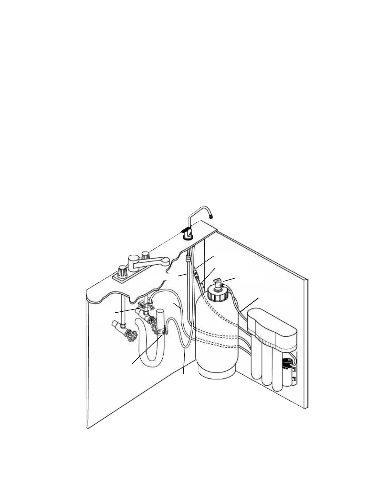
The exact placement of the various components of the
appliance will vary from installation to installation. The
installer, in conjunction with the customer, must decide on
where to place the faucet, tank and purification assembly by
balancing the homeowner's convenience with ease of installation and servicing. (See Fig. 1 & 7). A nearby electrical outlet
will also be required for proper installation of this device.
Considerations for an icemaker or other remote hookup
should be predetermined, including routing and any additional
tools, fittings, and tubing that may be required.
B. PREPARE THE AREA FOR INSTALLATION
Remove supplies from under the sink and stack them
area, if necessary.
components will be located and how they will be mounted.
secure the appliance to a wall or ceiling joists.
Inspect the cold water supply line and determine if any
special fittings, in addition to what is included in the kit, are
required.
NOTE:
undercounter plumbing for any existing or potential leaks. Any
items of concern should be repaired prior to installation of the
drinking water device.
Feedwater
Tapping
Valve
Drain Saddle
3/8” Blue Tubing
1/4” Orange
Sink Drain
Tubing
1/4” Green Tubing
Red SFC Tubing
Storage Tank
Valve
3/8” Yellow
Tubing
Storage Tank
3/8” Black
Tubing
Purification Assembly
* 110/60 (220/50) Electrical Connection
Necessary at This Location
Fig. 1
3

C.
PREPARE THE APPLIANCE FOR
INSTALLATION
Procedure:
Set up the chassis punch per the instructions and tighten the
-
Form a shallow putty dam around the hole area and fill it
Carefully drill a pilot hole through the porcelain/enamel and
Important:
Insert the pilot tip of the spring-loaded porcelain cutter into
porcelain cutter, making certain a complete ring has been
pressure, cut away the inner porcelain/enamel disc down
touch the outer rim of the cut porcelain/enamel. Continue
that it is always in a sharpened condition. Dull cutters are
Open the shipping carton and remove the components.
Check to see that all of the installation parts are present. They
should include the purification assembly, storage tank, faucet,
installation hardware, RO membrane cartridge and tubing.
Check to see that the air supply in the empty tank is approximately 7 psi (48 kPa). Adjust it if necessary. If an optional
percent rejection monitor is selected, the probes should be
installed at this time. Follow the instruction that came with the
monitor. To ensure you the highest level of purity, the RO
membrane cartridge has been shipped separately in a sealed
plastic bag. Follow the steps below to install the RO membrane cartridge.
STEP 1: Cut open the sealed plastic bag and remove the RO
membrane cartridge.
STEP 2: Remove the white plug from the fitting at the bottom
of the cartridge by pushing in the small gray collet and pulling
out the plug simultaneously. (See figure 6.)
STEP 3: Remove the red plastic cap from the top of the cartridge.
STEP 4: Connect the red SFC reject tubing by inserting the
open end into the fitting at the bottom of the RO membrane
cartridge as far as it will go. Take note of the tag attached to
the SFC tube which indicates the outlet end.
STEP 5: Line up the cartridge ears (Fig. 9), insert the cartridge
and push it into the head until it is fully seated. Twist the cartridge 1/4 turn counterclockwise to lock it into place. The final
orientation should be such that the cartridge label faces
towards the front and the fitting is located towards the rear.
D. MAKE THE FAUCET MOUNTING HOLE
A wide variety of RO faucet mounting situations may be
encountered. The most common are stainless steel or ceramic
on metal sinks. Consult your dealer for any other materials
which may be encountered.
The faucet should be positioned so that it empties into the
sink and the spout swivels freely for convenience.
If the sink already has a hole provided that can accommodate the RO faucet, then no drilling is required.
1) Center punch a small indent at the center of the desired
faucet location.
2) Slowly drill the required pilot hole for the chassis punch.
3)
nut to cut the desired hole size.
4) Clean up all sharp edges with a file if necessary.
Porcelain/Enamel/Ceramic sink on sheet metal or cast iron
base; air gap or non air gap faucet.
Recommended tools:
• Variable speed drill
• Relton 7/8" porcelain cutter tool set (alternate 9/16"
porcelain bit may be used for a non-air gap faucet)
• Plumber's putty
It is important to understand what is involved in this proce
dure. First, the glassy layer of porcelain must be penetrated
through to the base metal. Second, a center disc of porcelain
must be removed while protecting the surrounding porcelain
against chipping or fracturing. Third, the base metal must be
drilled through to complete the hole.
Procedure:
1) Mark the center for the 7/8" hole.
2)
with enough water to lubricate the carbide drill bit.
3)
the base metal using a carbide type pilot drill.
Always operate the drill with light pressure at a slow
speed (300-400 rpm).
4)
the pilot hole.
5) Drill the porcelain/enamel using the spring-loaded
cut through the porcelain/enamel to the metal base.
6) Change to the metal cutter. With a slow speed and light
to the base metal. Make certain that the cutter does not
NOTE: Sprayers can be disconnected to provide a suitable
mounting hole for the RO faucet. A pipe cap or plug will be
required to seal the sprayer connection.
IMPORTANT: It is mandatory that safety glasses by worn during the sink hole drilling operations in order to prevent eye injury.
Before drilling the hole, always check underneath the sink to
ensure that nothing will interfere with mounting the faucet such
as reinforcing ribs, support brackets or the cabinet construction.
Stainless steel sink, air gap or non-air gap faucet.
Recommended tools:
• Center punch
• Variable speed drill and high speed drill bits
• Greenlee 7/8" chassis punch (alternate 9/16" may be used
for a non-air gap faucet)
• Protective gloves
with this bit to cut completely through the metal.
IMPORTANT: When using a porcelain cutter it is critical
known to chip sinks.
4
E.
MOUNT THE FAUCET
Undercounter installations generally require that the
3)
Connect the 1/4" green tubing supplied in the installation
Connect the 3/8" black tubing to the larger barb on the air
and the threaded nipple through the faucet mounting hole
washer (open side toward the air gap tubes) between the
After rechecking the faucet orientation, tighten the hex nut
From above the sink, make any minor orientation corrections
faucet's built-in air gap be used. In basement installations, the
built-in air gap does not have to be used if one is provided
elsewhere on the drain line.
For Basement Installations Without An Air Gap Module
See Installation Instructions O.
IMPORTANT: The Uniform Plumbing Code dictates that there
must be an air gap between the RO reject line and the waste
drain. An optional non-air gap faucet, which requires a smaller
9/16" mounting hole, is available to make basement installations easier.
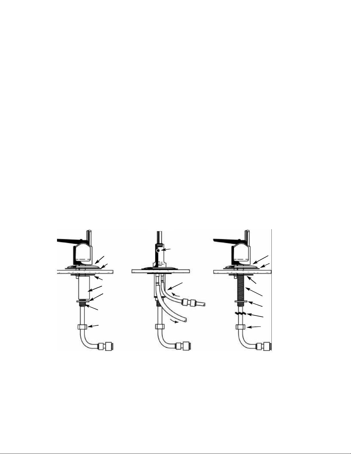
Undercounter Installation With An Air Gap Faucet:
1) Familiarize yourself with all of the components shown in
the air gap faucet diagram. (See Fig. 2)
2) Remove the hardware from the threaded nipple of the
faucet, except for the chrome base plate and the rubber
washer. The rubber washer may be replaced with a bead of
plumber's putty for a neater appearance.
kit to the smaller barb on the air gap faucet. Push it on
firmly until it seats.
4)
gap faucet. Push it on firmly until it seats.
5) From above the sink counter-top, feed the air gap tubing
and position the faucet spout over the sink.
6) From below the sink/countertop, install the white spacer
(open side toward the air gap tubing), flat washer and hex
nut onto the threaded nipple and tighten it by hand.
7) Back off on the hex nut just enough to slide the slotted
white spacer and the underside of the sink/countertop.
8)
with a 9/16" wrench until the faucet feels secure.
9)
by turning the faucet on its flats with a padded adjustable
wrench. Use care so as not to mar the chrome finish.
Faucet with Air Gap
Side View
Chrome base plate
Slotted washer
Spacer
Flat washer
Threaded nipple
Hex nut
Rubber washer
Blue 3/8” Product
water tubing
Back View
Air Gap hole
1/4” Standard
green tubing
Faucet without Air Gap
Side View
Special red “SFC”
tube from RO
Black 3/8” Reject
tubing to drain
Blue 3/8” Product
water tubing
Chrome base plate
Rubber washer
Plastic bottom washer
Threaded nipple
Flat washer
Star washer
Hex nut
Blue 3/8” Product
water tubing
Fig. 2
5
 Loading...