Water Boss 700, 900, 550 User Manual
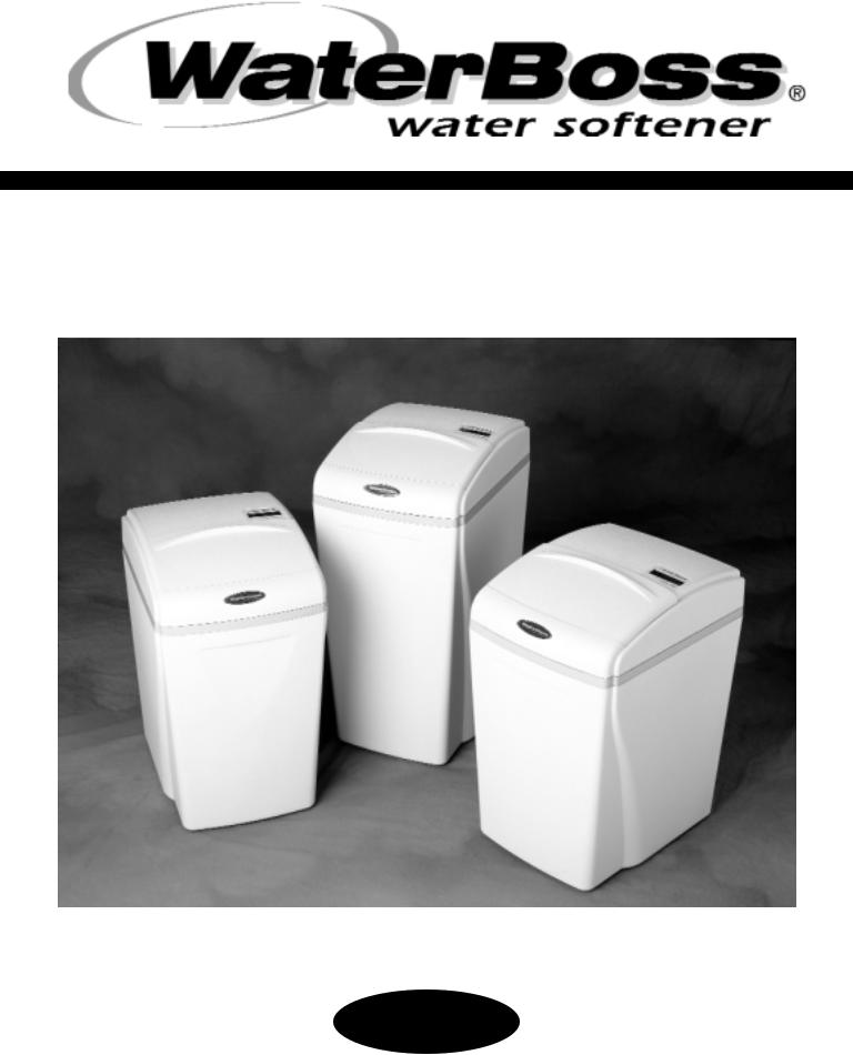
INSTALLATION AND SERVICE MANUAL
Model 550, 700 and 900 Water Softeners
Version 4
WaterBoss® 4343 S. Hamilton Road, Groveport, Ohio 43125

Table of Contents
QUESTIONS? ................................................................................................................. |
1 |
GETTING MAXIMUM EFFICIENCY FROM YOUR APPLIANCE ..................................... |
2 |
CHECKLIST BEFORE INSTALLATION............................................................................. |
3 |
DO'S AND DON’TS ......................................................................................................... |
4 |
REFERENCE ILLUSTRATIONS ....................................................................................... |
5 |
CYCLES .......................................................................................................................... |
10 |
INSTALLATION AND START-UP PROCEDURES .......................................................... |
11 |
SETTING THE 4 BUTTON CONTROLLER ..................................................................... |
13 |
ADVANCED SETTINGS FOR THE 4 BUTTON CONTROLLER ...................................... |
14 |
CARE, MAINTENANCE AND PARTS ............................................................................. |
16 |
SPECIFICATIONS/CAPACITY CHART ........................................................................... |
25 |
TROUBLESHOOTING ..................................................................................................... |
26 |
LIMITED WARRANTY ..................................................................................................... |
28 |
NOTES ............................................................................................................................. |
29 |
When calling the HelpLine, please have this guide and the serial number available. From 8 am to 5 pm EST, call 1-800-437-8993.
Your serial number may be found on top of your valve assembly.

Questions
From 8 am to 5 pm EST, use the 800 HelpLine: 1-800-437-8993
The HelpLine is available to help answer questions about specific water problems, appliance installation and operation. When calling the HelpLine, please have this guide and the serial number of your appliance available. Your serial number may be found on top of your valve assembly (See figures 2-3.)
Date of Installation: __________________________________
Model Number: _____________________________________
Serial Number: ______________________________________
Returned Limited warranty Card Date: ___________________
When calling the HelpLine, please have this guide and the serial number available. From 8 am to 5 pm EST, call 1-800-437-8993.
Your serial number may be found on top of your valve assembly.
1

How To Get The Maximum Efficiency From Your Appliance
1.Fill salt cabinet when water level is above salt level. DO NOT MIX DIFFERENT TYPES OF SALT.
If iron is present in your water, use a salt with an iron-cleaning additive to help keep resin clean. You may also use a resin cleaner on a monthly basis in place of salt with cleaning additives. If iron is not present in your water, a clean pellet, solar or cube type salt is recommended. The use of rock salt is not recommended because it contains impurities that can plug up the injector assembly.
2.You may use a salt substitute (such as potassium chloride) in place of water conditioner salt. If you start with water conditioner salt, you can switch to a salt substitute at any time - or vice versa. If potassium chloride is used in place of nugget or pellet salt, increase your hardness setting by 12% (multiply by 1.12). Do not use Potassium Chloride if there is iron in your water.
3.Should your electricity be turned off for any reason you must reset the time of day if you programmed your appliance for delayed regeneration.* (see page 14)
4.Protect your appliance from freezing, including drain line.
5.By-pass the appliance when servicing the well, plumbing, or pump. When work is completed, turn on the nearest cold water tap until water runs clear before putting appliance back in service. See figures 4 - 5 - 6.
6.Install after the pressure tank.
When calling the HelpLine, please have this guide and the serial number available. From 8 am to 5 pm EST, call 1-800-437-8993.
Your serial number may be found on top of your valve assembly.
2

Checklist Before Installation
1.Water Pressure - Not less than 20 psi constant for softeners.
2.Double check hardness - of water with test strips provided to verify that your appliance is right for the job.
Model 550 FOR MUNICIPALLY-SUPPLIED WATER is for water without iron and up to 25 grains of hardness per gallon.
Model 700 for up to 70 grains hardness per gallon.
Model 900 for up to 90 grains hardness per gallon. (See specifications, page 30.)
3.Water Supply Flow Rate - 5 gallons per minute is recommended as minimum.
4.Drain - Drain appliance to floor drain or washer drain. To prevent back-siphoning, the installer must provide an adequate air gap or a siphon break. See figure 1.
5.Electricity - The transformer supplied is a standard 120 volt, 60 cycle A.C. for USA or
220 volt, 50 cycle A.C. for outside the USA. See figure 8.
6.Water Quality - If the water supply contains sulfur, bacteria, iron bacteria, tannins, algae, oil, acid or other unusual substances, then unless the appliance is represented as being capable of treating these contaminants in the specifications, other special treatment of the water supply must be used to remove these contaminants before they enter this product.
If you have any questions call our HelpLine!
When calling the HelpLine, please have this guide and the serial number available. From 8 am to 5 pm EST, call 1-800-437-8993.
Your serial number may be found on top of your valve assembly.
3

Do’s And Don’ts
SOME DO'S
1.Do comply with all local plumbing and electrical codes.
2.Do install pressure-reducing valve if inlet pressure exceeds 90 psi.
3.Do install gravity drain on salt storage cabinet. See figure 7.
4.Do secure drain line on appliance and at drain outlet. See figure 3.
5.Do allow a minimum of 8 to 10 feet of 3/4” pipe from the outlet of the water conditioner to the inlet of the water heater. See figure 1.
SOME DON’TS
1.Do not install if checklist items are not satisfactory.
2.Do not install if incoming or outlet piping water temperature exceeds
120 degrees Fahrenheit. Please see specification on page 25.
3.Do not allow soldering torch heat to be transferred to valve components or plastic parts. See Installation Tip, page 6.
4.Do not overtighten plastic fittings.
5.Do not place appliance right up against a wall which would deny access to plumbing. See figure 1.
6.Do not install the appliance backwards. Follow arrows on inlet/outlet.
See figure 2.
7.Do not plug the transformer into an outlet that is activated by an on/off switch.
See figure 8.
8.Do not connect the drain and the overflow (gravity drain) together.
See figure 1.
When calling the HelpLine, please have this guide and the serial number available. From 8 am to 5 pm EST, call 1-800-437-8993.
Your serial number may be found on top of your valve assembly.
4
Reference Illustrations
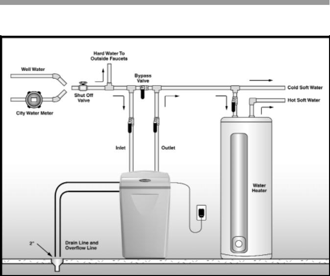
Figure 1 - Installation Guide
Use this diagram as a location and installation guide for your Model 550 , Model 700, and Model 900, water conditioners. This diagram applies to all types of installations
(i.e. basement, slab, crawl space, outside).
Bypass Valves. To simplify installation and servicing, a one-piece or a three way bypass valve appliance is recommended when installing your appliance. A bypass appliance also provides access to untreated water when required (i.e. for lawn and gardening purposes.)
Also, see figures 4 through 6.
Caution: If less than 10 feet of pipe connect the water treatment appliance(s), to the water heater, then a Check Valve must be installed between the water treatment appliance and the water heater. Install the Check Valve as close to the water heater as possible.
When calling the HelpLine, please have this guide and the serial number available. From 8 am to 5 pm EST, call 1-800-437-8993.
Your serial number may be found on top of your valve assembly.
5
Reference Illustrations
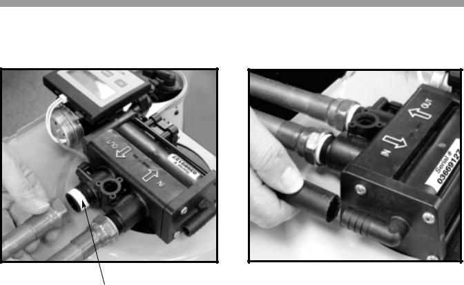
Figure 2
PLUMBING CONNECTIONS
Teflon® Tape
INSTALLATION TIP
Figure 3
CONNECTING DRAIN LINE
CAUTION! The drain line must not be kinked, crimped or restricted in any way.
The drain line should be a minimum 1/2" inside diameter and cannot be reduced in size.
When preparing the male threaded fittings of the I/O adapter, follow the guidelines to avoid damage to the plastic pipe threads.
1.For best results, use 1/2” wide Teflon® tape and wrap the threads three times with each consecutive wrap on top of the previous wrap. To prevent tearing of the the tape, use Teflon® paste on the first two threads only. This lubricates the tape and fills the small void areas that may exist between the threads. When the joint is complete, there will be a small bead of sealant at the fitting interface indicating a properly joined connection.
2.When preparing copper fittings, it is always advisable to use a union where there is a threaded connection to facilitate repairing a potential leak in one of your soldered joints.
3.To prevent heat damage to the plastic pipe threads of the adapter, prepare the copper tail assemblies ahead of time so they can cool down before final assembly. The copper tube length should be a minimum of 3-1/2” long. To prevent cross threading, turn the fitting counterclockwise until you feel the threads engage, then tighten. Do not overtighten the fittings.
CAUTION NOTE: To avoid damage, do not allow heat from the torch to be transferred to the plastic valve component.
6
Reference Illustrations
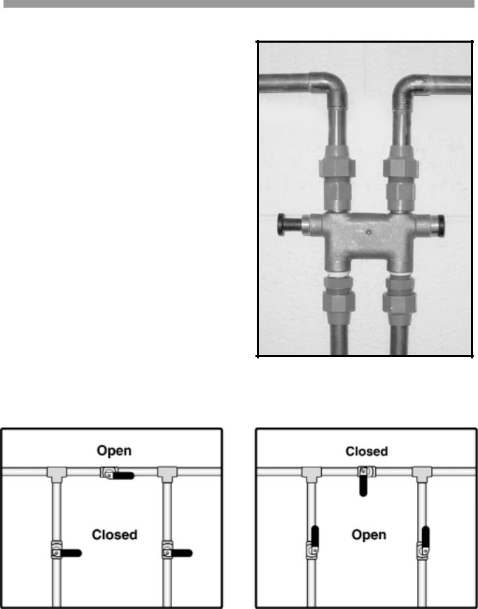
Figure 4 - Bypass Valve
Optional Bypass Valve Part #93884 may be available through your local hardware store, plumber or call our HelpLine 1-800-437-8993 From 8 am to 5 pm EST. to order.
< p u s h / p u l l >
for service or bypass.
Figure 5 - |
Figure 6 - |
In Bypass Position |
In Service Position |
7
Reference Illustrations
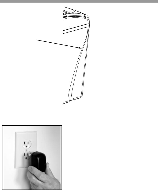
Figure 7
OVERFLOW
CONNECTION (1/2” I.D.)
Figure 8
PLUGGING IN TRANSFORMER
Do not plug transformer into an outlet that is controlled by on/off switch.
When calling the HelpLine, please have this guide and the serial number available. From 8 am to 5 pm EST, call 1-800-437-8993.
Your serial number may be found on top of your valve assembly.
8
 Loading...