

Page 1
Document revision: E
Page 2

Important Notice
Copyright © 2017 Enforcement Video, L.L.C. (dba WatchGuard Video). All rights reserved. This
document and supporting data are the exclusive property of Enforcement Video, L.L.C. and
may not be copied and/or reproduced without permission.
Firmware updates
WatchGuard Video is committed to the continual testing and improvement of our firmware. As
new firmware revisions become available, these updates will be made available to your agency;
fees may apply depending on your licensing agreement.
Manufacturer contact information
WatchGuard Video
Attn: Customer Service Department
415 Century Parkway
Allen, Texas 75013
800-605-6734
customerservice@watchguardvideo.com
Send us your suggestions
We want to hear from you. Tell us about your experience and how you are using the VISTA
Wearable Camera. We will do our best to accommodate any suggestions you may have in
future revisions.
For U.S. customers, call Customer Service at 800-605-6734 or email us at
customerservice@watchguardvideo.com with your comments, questions, and concerns.
International customers, please contact your local distributor.
Trademark notice
Microsoft, Windows, Windows Server, SQL Server, Active Directory, Exchange, .Net, and
Internet Explorer are trademarks or registered trademarks of Microsoft Corporation in the
United States and/or other countries.
VELCRO® is a registered trademark of Velcro Industries B. V.
RAM® is a registered trademark of National Products Inc. in the United States and/or other
countries.
iPhone® is a trademark of Apple Inc., registered in the U.S. and other countries.
Wi-Fi® is a registered trademark of Wi-Fi Alliance.
All other marks, names, and logos mentioned herein are the property of their respective
owners.
ii
VISTA Wearable Camera
WGD00120 Revision E
Page 3

Contents
Contents
Introduction 9
About this document 9
Related documents and information 10
What's new for version 2 10
Using VISTA 13
Overview 14
Basic VISTA workflow 14
Docking VISTA 15
Docking VISTA in a USB Base 15
Undocking VISTA from the USB Base 16
Docking VISTA in a VISTA Transfer Station 17
VISTA WiFi: Docking VISTA WiFi in a VISTA WiFi Base 18
Provisioning 20
VISTA configuration 20
Uploading 21
Record-After-the-Fact® events 22
Clearing video out of VISTA storage 22
Updating firmware 23
Charging 24
VISTA WiFi: Associating with a recording group 25
Wearing VISTA 26
Using the rotatable shirt clip and duty belt clip 26
Using the locking chest mount 27
Using the MOLLE vest loop mount 28
Powering On and Off 30
Powering on 30
Powering off 30
Forcing power off 31
Starting and Stopping a Recorded Event 31
Starting a recorded event manually 31
VISTA Wearable Camera
WGD00120 Revision E
iii
Page 4

Contents
Stopping a recorded event manually 32
Muting the Audio During a Recorded Event 33
Muting VISTA audio 33
Categorizing a Recorded Event 34
Categorizing a recorded event on VISTA 34
About VISTA 35
Overview 36
Video, Audio, and Subtitle Evidence 36
Video 37
Audio 37
Subtitles 37
Camera Components 38
Camera sensor and lens 39
Microphone 39
Buttons 39
Power button 39
Record Start/Stop button 40
Display Backlight button 40
LCD Display 40
Feedback indicators 42
Storage 42
Battery 43
LOW BATT message 44
LOW BASE message 44
VISTA WiFi: Wi-Fi 44
VISTA WiFi: GPS 45
GPS signal status 45
Quick mounting latch 46
Available Mounts 47
Rotatable shirt clip 47
Locking chest mount 48
Duty belt clip 48
MOLLE vest loop mount 49
Other mounts 49
iv
VISTA Wearable Camera
WGD00120 Revision E
Page 5

Contents
About the USB Base 50
Setting up the VISTA USB Base 50
About the VISTA Transfer Station 51
Setting up the VISTA Transfer Station 52
VISTA WiFi: About the VISTA WiFi Base 52
Setting up the VISTA WiFi Base 54
VISTASpecial Features 55
Overview 56
Recording special features 56
Battery and storage saving special features 56
Covert Mode 57
Pre-Event Capture 57
Audio 57
Record-After-the-Fact® 58
Generating an RATF event 58
Storage 58
Audio 59
Force Microphone On 59
Sleep Power State 60
Sleep warning period 60
Exiting Sleep state 60
Automatic Off 61
Maximum Recorded Event Time 61
Maximum Recorded Event Time warning period 61
Recording Reminder Alert 62
Covert Mode 62
VISTA WiFi: Using VISTAWiFi with a Recording Group 63
Overview 64
Recording groups 65
Members of the recording group 65
Smart Power Switch 66
4RE DVR 66
VISTA WiFi Base 67
VISTA WiFi 67
VISTA Wearable Camera
WGD00120 Revision E
v
Page 6

Contents
Other devices in the system 68
Group recordings 69
VISTA WiFi behavior during a group recording 69
Appendix A: Using VISTA SmartConnect 71
Overview 72
Activating the VISTA WiFi hotspot 72
Connecting to VISTA SmartConnect 73
Connecting VISTA WiFi to SmartConnect for the first time 73
Connecting VISTA WiFi to SmartConnect after the first time 75
Reviewing VISTAWiFi Recorded Events with SmartConnect 76
Capturing snapshots 77
Categorizing Recorded Events Using SmartConnect 78
Live Streaming VISTAWiFi with SmartConnect 79
Other features 80
Starting and Stopping Recorded Events Using SmartConnect 81
SmartConnect Settings 82
Camera Settings 83
Camera Data 83
Appendix B: VISTA Transfer Station Setup 85
Overview 86
VISTA Transfer Station Hardware 87
Setting up the hardware 87
VISTATransfer Station Configuration 89
Transfer Station Settings 89
Static IP 89
DHCP and Date/Time Settings 90
VISTASettings 90
DHCP 90
Static IP 91
Transfer Station administrative functions 91
Upgrading the Transfer Station software or firmware 91
Changing the login credentials for the Transfer Station configuration page 92
Disabling the configuration page 92
Restarting the Transfer Station 93
vi
VISTA Wearable Camera
WGD00120 Revision E
Page 7

Contents
Configuring the Transfer Station 93
Index 97
VISTA Wearable Camera
WGD00120 Revision E
vii
Page 8

Contents
This page intentionally left blank.
viii
VISTA Wearable Camera
WGD00120 Revision E
Page 9

Introduction
Introduction
Welcome to the WatchGuard® Video VISTA HD Wearable Camera User Guide. This guide is
designed to walk you through the basics of using your VISTA™ Wearable Camera to collect
quality video evidence.
About this document
The VISTA HD Wearable Camera User Guide covers the basic components and operation of
VISTA and VISTA WiFi including:
l Docking, charging, provisioning, and uploading
l Associating with a recording group (VISTA WiFi only)
l Powering on and off
l Wearing VISTA
l Recording evidence
l Categorizing events
This guide includes a section on VISTA special features:
l Pre-event and Record-After-the-Fact® (RATF)
l Automatic sleep and power off to help you save battery
l Maximum recording length and periodic recording alerts to help you save storage space
l Covert Mode
This guide also includes a section on recording groups and how VISTA WiFi and the WiFi Base
work within a local recording group network.
Two appendices to the guide contain:
l Instructions for using the VISTA SmartConnect smartphone app with VISTA WiFi
l Instructions for setting up the VISTA Transfer Station
Note: This user guide covers the basic use of the VISTA Wearable Camera. It is
not a comprehensive manual for every possible action or situation you could
experience when using VISTA. If you have a question about VISTA that is not
covered in the user guide, contact your WatchGuard Video representative.
VISTA Wearable Camera
WGD00120 Revision E
9
Page 10

Introduction
Related documents and information
For subjects related to the WatchGuard Video video evidence system that are not covered by
the VISTA HD Wearable Camera User Guide, see the following documents:
l VISTA HD Wearable Camera Quick Start Guide
l Evidence Library 4 Web User Guide
l Evidence Library Express User Guide
l 4RE In-Car Video User Guide
l 4RE Vehicle Installation Instructions
What's new for version 2
The following features are new for version 2 of the WatchGuard Video VISTA Wearable Camera:
l Optional Wi-Fi™ (page 44) and GPS (page 45) (VISTA WiFi only)
Version 2 gives you the option of adding 802.11n Wi-Fi and GPS date/time and location
information to the VISTA Wearable Camera. Wi-Fi allows the VISTA WiFi camera to participate
in group recordings and provide an access point (hotspot) for the VISTA SmartConnect
smartphone application. GPS date and time allows your Evidence Library software to
synchronize playback of recorded events.
l Support for recording groups/group recordings (Distributed Multi-Peer
Recording™) (VISTA WiFi only) (page 63)
o
Evidence Library software configuration items (page 20)
o
Pairing with VISTA WiFi Base (page 25)
Version 2, VISTA WiFi option, gives you the ability to associate your VISTA WiFi cameras with
local recording group networks to create group recordings.
l Support for the VISTA SmartConnect iPhone® application (VISTA WiFi only) (page
71)
Version 2 gives you the ability to set up VISTA WiFi to connect to and interact with the VISTA
SmartConnect iPhone application.
l Support for additional VISTAconfiguration options, including:
o
Muting recorded event audio (page 33)
o
Recorded event stop confirmation (page 32)
o
Wireless event upload to Evidence Library 4 Web (EL4 Web) through the VISTA
WiFi Base (page 21)
Version 2 gives you the ability to apply the additional VISTA configuration options and features
offered with Evidence Library Express, version 3.5 or Evidence Library 4 Web, version 4.1.
l Improved Sleep power state (page 60)
Version 2 allows VISTA to remain in its Sleep state longer and exit its Sleep state significantly
faster than previous versions.
10
VISTA Wearable Camera
WGD00120 Revision E
Page 11

What's new for version 2
The following products are new in support of version 2 of the VISTA Wearable Camera:
l VISTA WiFi Base (page 52)
The VISTA WiFi Base functions as an 802.11n Wi-Fi access point (hotspot) for VISTA WiFi. The
WiFi Base pairs with VISTA WiFi, allowing the camera to associate with the local recording group
network.
l Smart Power Switch (page 66)
The Smart Power Switch functions as the central connection point for the local recording group
network that includes VISTA WiFi.
l VISTA SmartConnect iPhone application (page 71)
The VISTA SmartConnect app, when connected to VISTA WiFi, makes additional VISTA WiFi
functionality available on your iPhone.
VISTA Wearable Camera
WGD00120 Revision E
11
Page 12

Introduction
This page intentionally left blank.
12
VISTA Wearable Camera
WGD00120 Revision E
Page 13

Using VISTA
In this section...
l Basic VISTA workflow (page 14)
l Docking VISTA (page 15)
o
In the USB base (page 15)
o
In the VISTA Transfer Station (page 17)
o
In the VISTA WiFi Base (page 18)
o
Provisioning the camera (page 20)
o
Uploading recorded events from camera storage (page 21)
o
Updating the camera's firmware (page 23)
o
Charging the camera's battery (page 24)
o
VISTA WiFi: Associating with a recording group (page 25)
Using VISTA
l Wearing VISTA (page 26)
l Powering VISTA on and off (page 30)
l Recording evidence (page 31)
l Categorizing a recorded event (page 34)
VISTA Wearable Camera
WGD00120 Revision E
13
Page 14
Using VISTA
Overview
You use the VISTA Wearable Camera as a DVR (digital video recorder) to capture, process, and
store video and audio evidence. You connect VISTA with your Evidence Library software to
provision it as well as to upload its video for evidence management.
If your agency is using VISTA WiFi, you can pair VISTA WiFi with a WiFi Base that is associated
with a 4RE DVR. The devices together form a recording group.
Note: Not all VISTA Wearable Cameras or VISTA bases have the Wi-Fi® feature.
If you are not sure whether your equipment has the Wi-Fi feature, contact your
WatchGuard Video representative.
Basic VISTA workflow
The following steps make up a basic workflow for using VISTA during your shift:
1. Provision VISTA and then check it out using your Evidence Library software. (page 20)
2. Undock VISTA.
3. (VISTA WiFi only) Dock VISTA WiFi in the VISTA WiFi Base (WiFi Base). (page 25)
This action pairs the camera with the base and associates VISTA WiFi with the local recording
group.
4. (VISTA WiFi only) Undock VISTA WiFi after it has paired with the VISTA WiFi Base.
5. Attach VISTA securely to your clothing. (page 26)
6. Start and stop recorded events. (page 31)
7. Categorize recorded events. (page 34)
8. Power VISTA off or on, as needed. (page 30)
9. Dock VISTA to upload recorded events (page 21) and charge its battery (page 24).
14
VISTA Wearable Camera
WGD00120 Revision E
Page 15
Docking VISTA
Docking VISTA
Docking the VISTA Wearable Camera allows you to perform a number of tasks with the camera.
WatchGuard Video offers three different bases where you can dock your VISTA camera:
l USB Base (below)
l VISTA Transfer Station (page 17)
l VISTA WiFi Base (page 18)
You can dock VISTA in any of the three available bases, but each base functions a little
differently from the others.
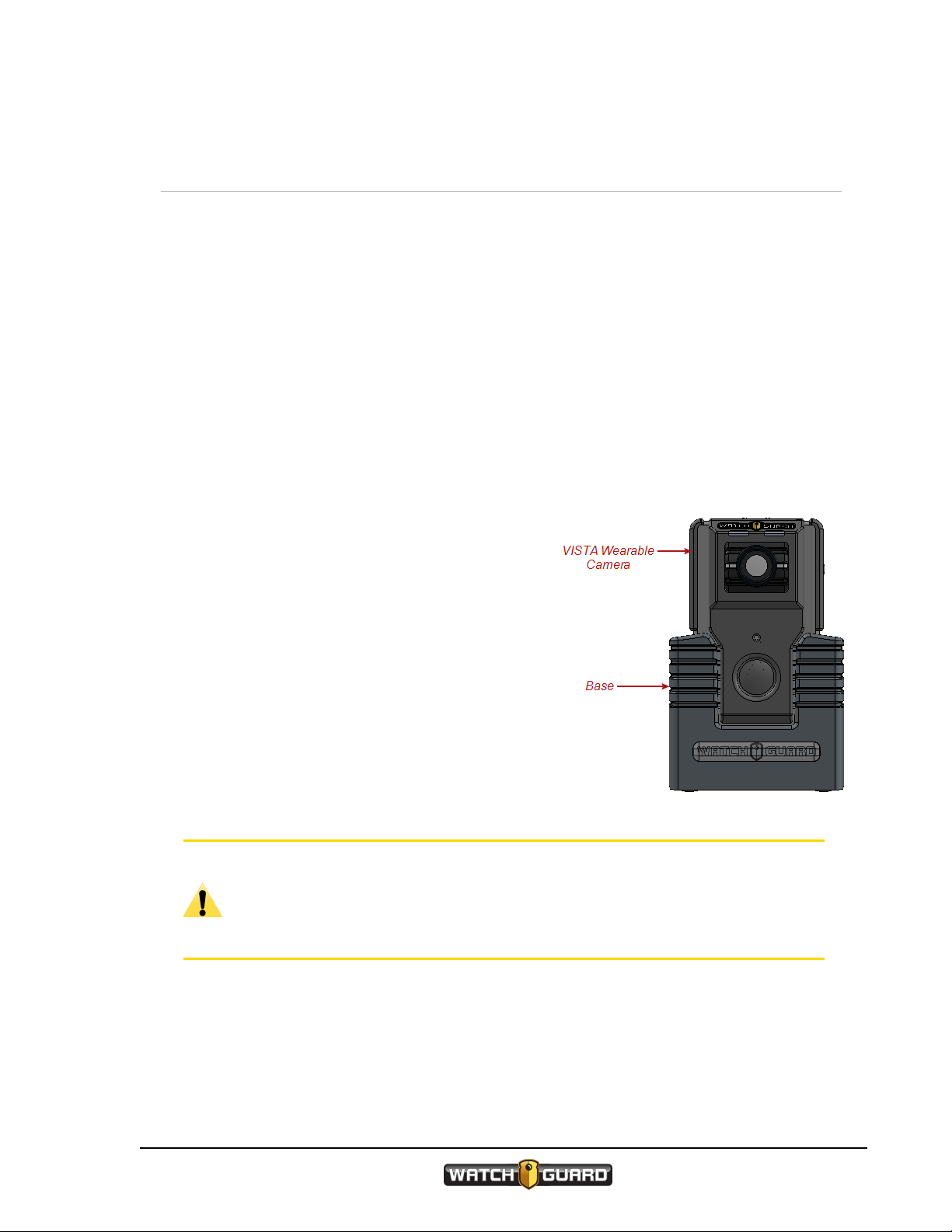
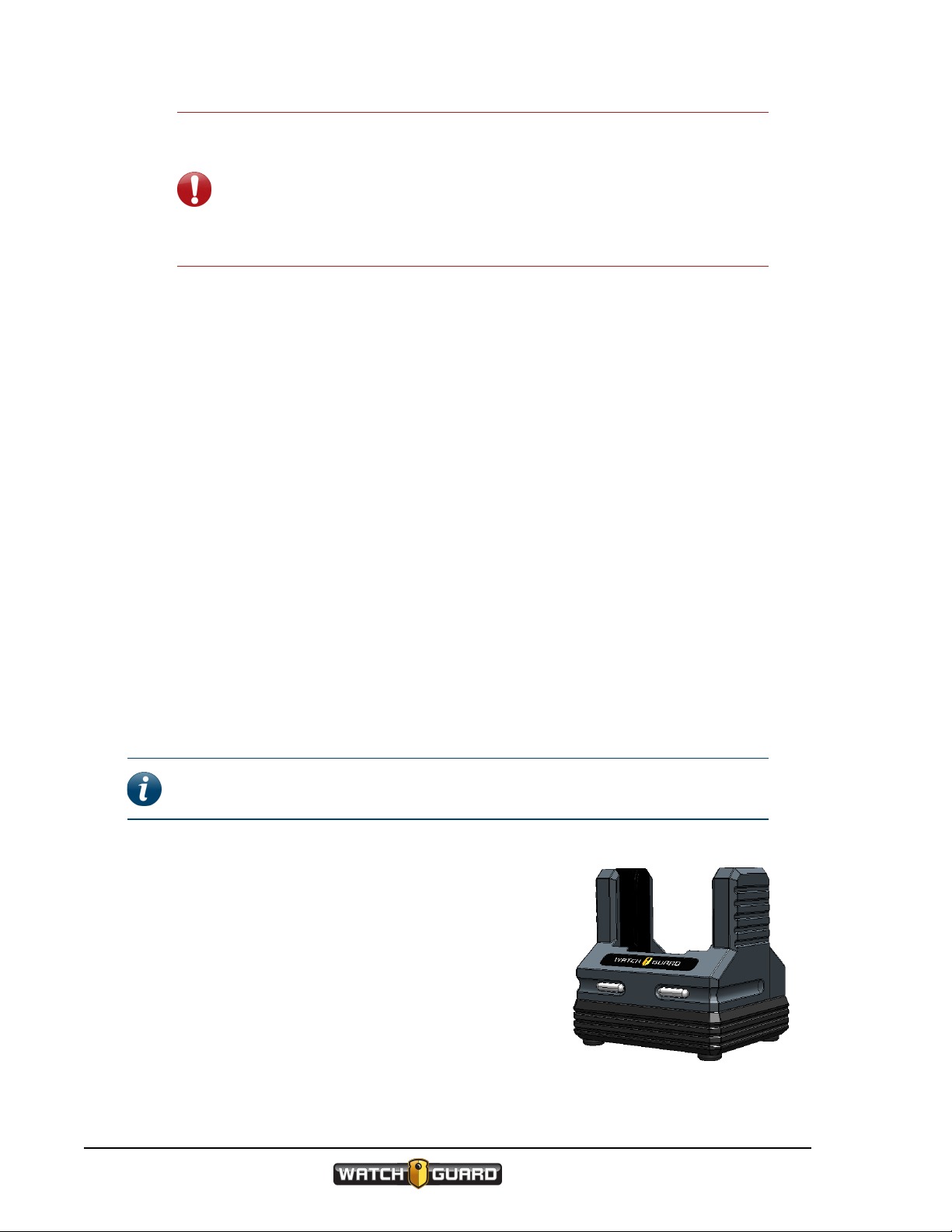
Docking VISTA in a USB Base
Docking the VISTA Wearable Camera in a USB Base allows you to perform the following tasks:
l Provision the camera (page 20)
l Upload recorded events from camera storage
(page 21)
l Update the camera's firmware (page 23)
l Charge the camera's battery (page 24)
l Define a Record-After-the-Fact
event (page 22)
l Request a state capture for troubleshooting
®
(RATF)
VISTA needs to interact with Evidence Library
software to be customized for your agency. For that
interaction to take place, VISTA must be docked in a
VISTA USB Base (or Transfer Station) connected to
your Evidence Library software.
Caution: Some computers can be damaged when the USB Base is plugged into
an electrical outlet for power then directly into the computer using the USB cable.
To prevent this from happening, connect the USB Base to the computer through
the approved USB hub (Sabrent 7-Port USB 2.0 Hub, WatchGuard Video part
number WGP02364).
VISTA Wearable Camera
WGD00120 Revision E
15
Page 16

Using VISTA
When you dock VISTA in a USB Base connected to Evidence Library software:
l VISTA's battery begins to charge, if needed
l VISTA's time and date synchronize with the Evidence Library system, if needed (VISTA without
Wi-Fi® and GPS only)
Important! VISTA cameras without Wi-Fi and GPS set their internal
date and time from the date and time on your Evidence Library software's
computer. If the computer's date and time is set incorrectly, VISTA's date
and time will be set incorrectly, and your video evidence will be marked
with the incorrect date and time.
VISTA WiFi (VISTA with Wi-Fi and GPS) sets its own date and time.
l VISTA's firmware updates, if a firmware update has been staged on the camera
l VISTA communicates to the Evidence Library software that it has recorded events to upload, if
applicable
l Recorded events are uploaded to the Evidence Library software
l Evidence Library software sends commands and/or requests to VISTA:
o
Mark any imported recorded events as import confirmed
The events confirmed as imported are no longer protected once VISTA is undocked.
o
Update the configuration, if applicable
The configuration is updated after VISTA is undocked.
o
Stage a firmware update, if applicable
The firmware update is staged on VISTA immediately, and then updated the next time
VISTA is docked.
o
Generate an RATF event, if applicable
The RATF event is generated after VISTA is undocked.
o
Generate a state capture, if applicable
The state capture is generated after VISTA is undocked.
When you undock VISTA from the USB Base, it processes any Evidence Library software
commands and requests before it is ready for normal operation.
Undocking VISTA from the USB Base
When VISTA is docked in the USB Base, Evidence Library software commands and requests are
not applied until VISTA is undocked. When you undock VISTA, it processes the Evidence Library
software's commands and requests in the following order, as applicable:
1. Performs a state capture.
The LCD Display reads STATE CAPTURE.
2. Updates the configuration.
The LCD Display reads CONFIG. The configuration update alert sounds when the update is
finished.
16
VISTA Wearable Camera
WGD00120 Revision E
Page 17
Docking VISTA in a VISTA Transfer Station
3. Generates an RATF event.
The LCD Display reads CREATING RATF.
Note: After the RATF event has been generated, VISTA starts the event
categorization sequence for the RATF event if it is configured to require
event categorization. For instructions how to categorize an event on
VISTA, see Categorizing a Recorded Event on page 34.
4. Unprotects the recorded events confirmed as imported. This makes the storage space available
to be reused as needed.
5. Stages the firmware update to perform the next time it is docked.
Once all the commands and/or requests are processed, VISTA is ready for normal operation.
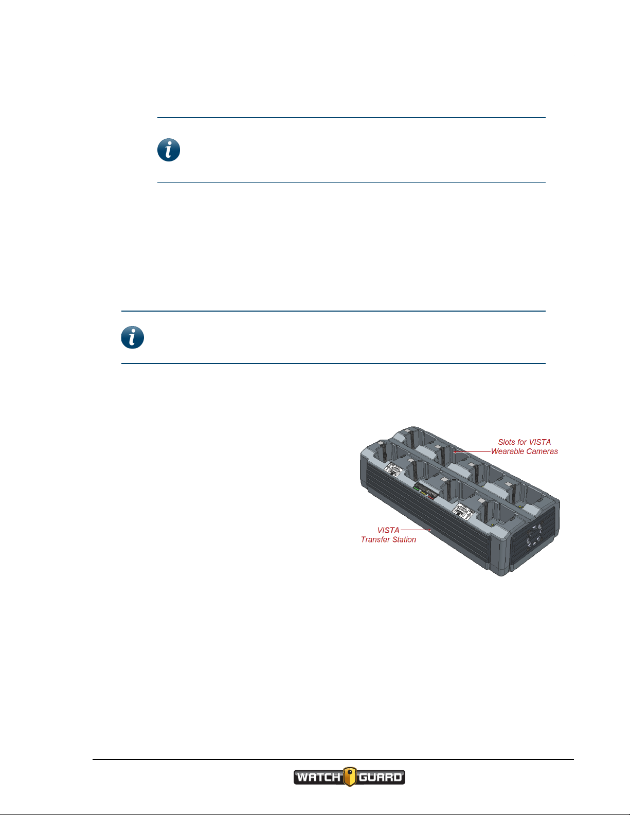
Docking VISTA in a VISTA Transfer Station
Note: The VISTA Transfer Station must be set up and configured to be used with
your Evidence Library software. For instructions how to set up the Transfer
Station, see Appendix B: VISTA Transfer Station Setup on page 85.
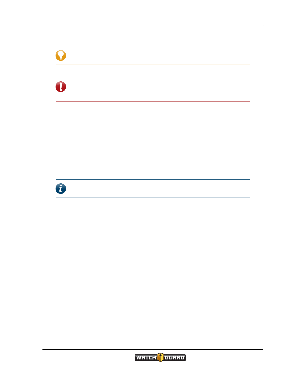
Docking the VISTA Wearable Camera in a VISTA Transfer Station allows you to perform the
following tasks:
l Provision the camera (page 20)
l Upload recorded events from camera
storage (page 21)
l Update the camera's firmware (page 23)
l Charge the camera's battery (page 24)
VISTA needs to interact with Evidence Library
software to be customized for your agency. For
that interaction to take place, VISTA must be
docked in a VISTA Transfer Station (or USB Base)
connected to your Evidence Library software.
When you dock VISTA in a Transfer Station
connected to Evidence Library software:
l VISTA's battery begins to charge, if needed
l VISTA's time and date synchronize with the Evidence Library system, if needed (VISTA without
Wi-Fi® and GPS only)
VISTA Wearable Camera
WGD00120 Revision E
17
Page 18
Using VISTA
Important! VISTA cameras without Wi-Fi and GPS set their internal
date and time from the date and time on your Evidence Library software's
computer. If the computer's date and time is set incorrectly, VISTA's date
and time will be set incorrectly, and your video evidence will be marked
with the incorrect date and time.
VISTA WiFi (VISTA with Wi-Fi and GPS) sets its own date and time.
l VISTA's firmware updates, if a firmware update has been staged on the camera
l VISTA communicates to the Evidence Library software that it has recorded events to upload, if
applicable
l Recorded events are uploaded to the Evidence Library software
l Evidence Library software sends commands and/or requests to VISTA:
o
Mark any imported recorded events as import confirmed
The events confirmed as imported are immediately unprotected. This makes the storage
space available to be reused as needed.
o
Update the configuration, if applicable
If the configuration is manually pushed to VISTA (through the Evidence Library
checkout process), the configuration is updated immediately.
If the configuration is automatically pushed to VISTA, the configuration is updated
after VISTA is undocked.
o
Stage a firmware update, if applicable
The firmware update is staged on VISTA immediately, and then is updated the next time
VISTA is docked.
When you undock VISTA from the Transfer Station, it is ready for normal operation.
VISTA WiFi: Docking VISTA WiFi in a VISTA WiFi Base
Note: Not all VISTA Wearable Cameras or VISTA bases have the Wi-Fi® feature.
For more information, contact your WatchGuard Video representative.
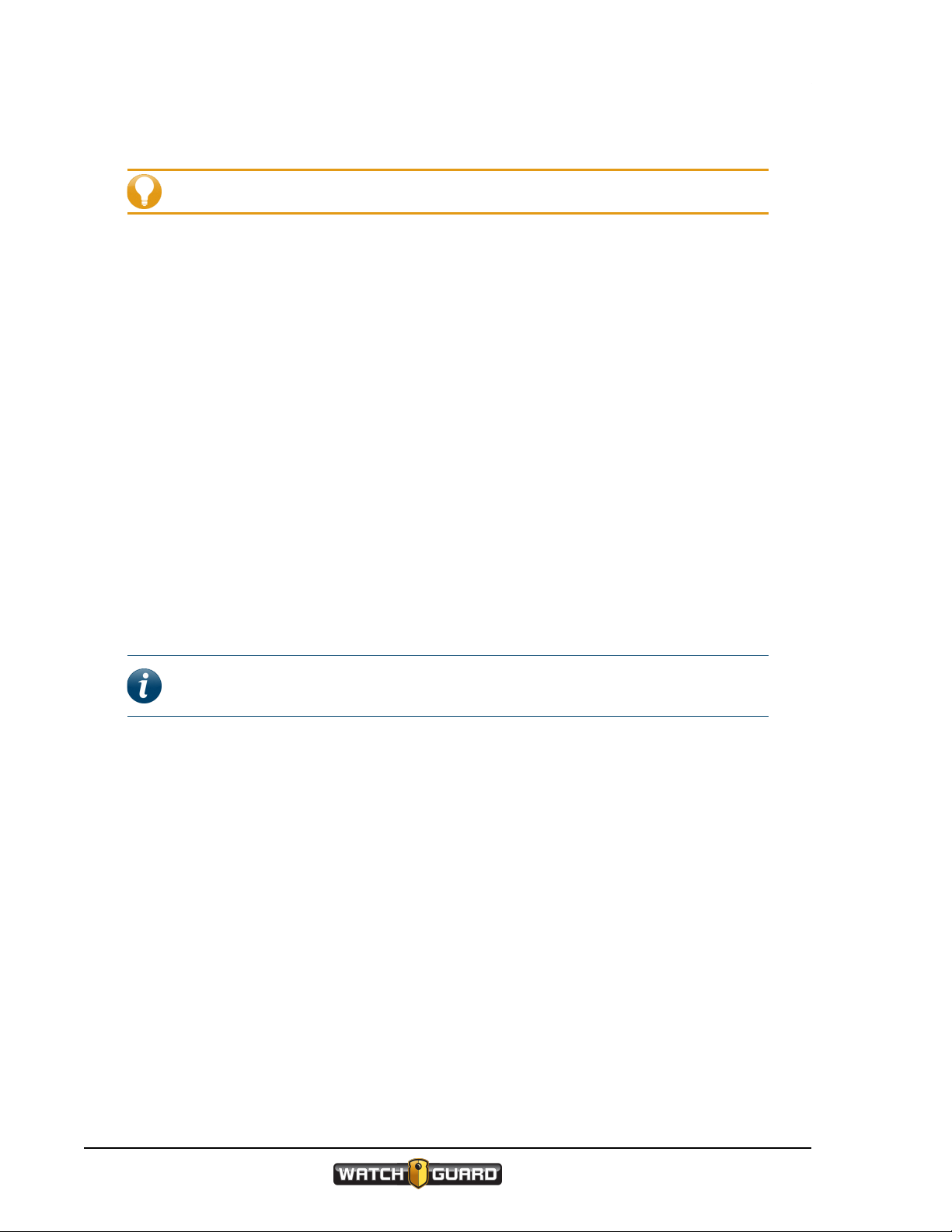
Docking VISTA WiFi in a VISTA WiFi Base allows you to perform
the following tasks:
l Associate with a recording group that can include a 4RE
DVR and other VISTA cameras (page 25)
l Update the camera's firmware (page 23)
l Upload recorded events from the camera's storage
(page 21)
l Charge the camera's battery (page 24)
You should only use the WiFi Base for incidental charging
during your shift. Charging in a vehicle base can impact
18
VISTA Wearable Camera
WGD00120 Revision E
Page 19
VISTA WiFi: Docking VISTA WiFi in a VISTA WiFi Base
the vehicle battery and can slow down significantly in warmer temperatures.
Tip: Use the USB Base or the Transfer Station inside your agency when fully
charging the VISTA battery.
Important! VISTA WiFi needs to interact with Evidence Library software to be
customized for your agency. For that interaction to take place, VISTA WiFi must
initially be docked in a VISTA USB Base or Transfer Station connected to your
Evidence Library software.
When you dock VISTA WiFi in a WiFi Base:
l VISTA WiFi's battery begins to charge, if needed
l VISTA WiFi's firmware updates, if a firmware update has been staged on the camera
l VISTA WiFi pairs with the WiFi Base; when it does, it becomes associated with the local
recording group
When VISTA WiFi becomes associated with the local recording group, it is disassociated from
any other recording group.
When you dock VISTA WiFi in a WiFi Base that is connected (wired or wirelessly) to an Evidence
Library 4 Web upload server:
Note: WatchGuard Video recommends that you use version 4.1 (or higher) of
EL4 Web for the best experience.
l VISTA WiFi communicates to EL4 Web that it has recorded events to upload, if applicable
VISTA WiFi must be configured to upload events directly to EL4 Web from the WiFi Base.
l Recorded events are uploaded to EL4 Web, if applicable
l EL4 Web sends commands and/or requests to VISTA WiFi:
o
Mark any imported recorded events as import confirmed
The events confirmed as imported are immediately unprotected. This makes the storage
space available to be reused as needed.
o
Stage a firmware update, if applicable
The firmware update is staged on VISTA WiFi immediately. The firmware is updated the
next time VISTA WiFi is docked.
When you undock VISTA WiFi from the WiFi Base, it is ready for normal operation.
For more information about...
The VISTA WiFi Base, see VISTA WiFi: About the VISTA WiFi Base on page 52.
Recording groups, see VISTA WiFi: Using VISTAWiFi with a Recording Group on page 63.
VISTA Wearable Camera
WGD00120 Revision E
19
Page 20
Using VISTA
Provisioning
Tip: Before using VISTA for the first time, fully charge and provision it.
You provision your VISTA Wearable Camera while it is docked in a USB Base or VISTA Transfer
Station. When you provision VISTA, you use your WatchGuard Video Evidence Library software
to assign a configuration and an officer name.
Depending on how your agency assigns its VISTA cameras, you may need to provision and
check out VISTA each time you use it (for example, from a pool of VISTA cameras) or only rarely
as its configuration needs to be updated (for example, if a VISTA camera has been assigned to
you long-term).
To provision VISTA:
1. Dock VISTA in the USB Base or Transfer Station connected to your Evidence Library software.
2. Using Evidence Library software, create and/or assign a configuration and an officer to the
docked VISTA.
For instructions how to assign a configuration and officer to VISTA, see your Evidence Library
software documentation.
During the provisioning process, VISTA must remain docked.
VISTA configuration
You can only create a VISTA configuration in your Evidence Library software.
Note: For specific instructions how to create and set up a configuration for
VISTA, see your Evidence Library software documentation.
Some of the configuration properties you can set up for VISTA in your Evidence Library software
include:
l Agency or department name
l Time zone where the agency or department is located
l Officer name and badge ID
l VISTA device ID
l Event tags including a list of possible event categories (page 34)
l Officer preferences for indicators, including (page 42)
o
Alert preference (none, tone, vibration, or tone and vibration together)
o
LED brightness
o
Tone volume
l VISTA WiFi behaviors, including
o
Recording group interactions (page 63)
o
Allow connection to the VISTA SmartConnect smartphone app (page 71)
20
VISTA Wearable Camera
WGD00120 Revision E
Page 21

l Network preferences, including
o
Allow VISTA to upload to Evidence Library 4 Web (EL4 Web) when docked in VISTA WiFi
Base (EL4 Web only)
o
Maximum wireless upload time (EL4 Web only)
l Recording preferences, including
o
Video quality and frame rate
o
Enable Record-After-the-Fact®(RATF) (page 58)
o
Force microphone on all the time (page 59)
o
Enable pre-event capture (page 57)
o
Enable split events
o
Allow audio muting (page 33)
o
Require confirmation of recorded event stop
l Power- and storage-saving preferences, including
o
Allow sleep (page 60)
o
Allow automatic power off (page 61)
o
Enable maximum recorded event time (page 61)
o
Enable recording reminder alerts (page 62)
Uploading
Uploading
You can upload recorded events from your VISTA Wearable Camera while it is docked in any of
the three bases:
l USB Base
You can upload recorded events automatically or manually from a VISTA in a USB Base,
depending on the settings in your Evidence Library software.
l VISTA Transfer Station
Events upload automatically from a VISTA in the VISTA Transfer Station.
l VISTA WiFi Base
Events upload from a VISTA (typically VISTA WiFi) in the WiFi Base, ONLYIF the WiFi Base is
connected (wired or wirelessly) to an Evidence Library 4 Web (EL4 Web) upload server. The
events upload automatically.
Note: VISTA must be configured to upload events to EL4 Web from the
WiFi Base.
You use your WatchGuard Video Evidence Library software to manage all aspects of the upload
and import.
VISTA Wearable Camera
WGD00120 Revision E
21
Page 22

Using VISTA
To upload recorded events from VISTA:
1. Dock VISTA in a base or Transfer Station connected to your Evidence Library software.
The Evidence Library software automatically detects that VISTA is docked in a USB
Base or VISTA Transfer Station and that it has events to upload. The events begin to
upload automatically if applicable.
EL4 Web automatically detects that VISTA WiFi is docked in a WiFi Base and that it has
events to upload. The events begin to upload automatically if applicable.
2. Follow any prompts in the Evidence Library software to upload video from VISTA and import it
to evidence storage.
For instructions how to import video from VISTA to your evidence storage, see your Evidence
Library software documentation.
During the upload process, VISTA must remain docked in the base or Transfer Station.
Record-After-the-Fact®events
If VISTA is configured with Record-After-the-Fact (RATF) enabled and it is docked in a USB Base,
you can use the Evidence Library software to define and request an RATF event from VISTA.
(An RATF event usually consists of video that was not originally part of a recorded event.) VISTA
generates the RATF event after you undock it, then uploads the RATF event the next time you
dock for upload.
For more information about...
VISTA and RATF events, see Record-After-the-Fact® on page 58.
Recorded events, see Video, Audio, and Subtitle Evidence on page 36.
How to define and request an RATF event from VISTA, see your Evidence Library software
documentation.
Clearing video out of VISTA storage
Once VISTA has successfully uploaded its recorded events to evidence storage using Evidence
Library software, VISTA no longer protects that storage space. It can then be used for future
recorded events.
22
VISTA Wearable Camera
WGD00120 Revision E
Page 23
Updating firmware
Updating firmware
While the VISTA Wearable Camera is docked, your Evidence Library software determines
whether the camera's firmware needs to be updated. If VISTA needs an update, the Evidence
Library software can push the new firmware to the camera.
You can push new firmware to your VISTA Wearable Camera while it is docked in any of the
three bases:
l USB Base
You can push a firmware update to VISTA automatically or manually when it is docked in a USB
Base, depending on the settings in your Evidence Library software.
l VISTA Transfer Station
You can push a firmware update to VISTA automatically when it is docked in a VISTA Transfer
Station.
l VISTA WiFi Base
You can push a firmware update to VISTA (typically VISTA WiFi) when it is docked in a VISTA
WiFi Base, ONLYIF the WiFi Base is connected (wired or wirelessly) to an Evidence Library 4
Web (EL4 Web) upload server. The firmware update is pushed automatically.
When new firmware is pushed to VISTA, the firmware is staged on the camera, then the next
time the camera is docked, the firmware is updated.
To update VISTA's firmware:
1. Dock VISTA in a base or Transfer Station connected to your Evidence Library software.
The Evidence Library software automatically detects that VISTA is docked and that its
firmware needs to be updated.
2. Using Evidence Library software, make sure the new firmware is pushed to VISTA.
Note: Evidence Library software can be set up to push firmware
manually or automatically to VISTA. For instructions how to push new
firmware manually and/or automatically to VISTA, see your Evidence
Library software documentation.
The new firmware is staged on the VISTA camera.
3. The next time you dock the camera, the firmware is updated.
The camera cannot perform any other function, including uploading video, while it is updating
its firmware. While the firmware is updating, UPDATING DO NOTINTERRUPT shows in the
LCD Display.
Warning! DONOT REMOVE VISTA from the dock while its firmware is
updating. Removing VISTA from the dock during the firmware update
can cause the camera to stop functioning.
When the firmware update has finished, VISTA sounds the camera ready alert (depending on
your alert notification selections).
VISTA Wearable Camera
WGD00120 Revision E
23
Page 24
Using VISTA
Charging
Tip: Before using VISTA for the first time, fully charge and provision it.
The VISTA Wearable Camera charges any time it is docked, if it needs to charge. The VISTA
battery can fully charge in 3 to 5 hours.
Tip: WatchGuard Video recommends that you use the USB Base or the Transfer
Station inside your agency when fully charging the VISTA battery. Charging in a
vehicle base can impact the vehicle battery and can slow down significantly in
warmer temperatures.
To fully charge VISTA:
n Dock VISTA in either the USB Base or the Transfer Station inside your agency.
VISTA can charge in a USB Base connected to the USBport on a computer, depending on the
voltage provided by the USB port. The camera charges significantly faster when docked in a USB
Base that is plugged into an electrical outlet or in a VISTA Transfer Station.
Caution: Some computers can be damaged when the USB Base is plugged into
an electrical outlet for power then directly into the computer using the USB cable.
To prevent this from happening, connect the USB Base to the computer through
the approved USB hub (Sabrent 7-Port USB 2.0 Hub, WatchGuard Video part
number WGP02364).
While VISTAis charging, the Battery Charge icon on the display animates and the green LED
blinks. The LCD Display alternates between CHARGING and the VISTA Device ID.
When VISTA is fully charged, the green LED lights steadily and two tones sound. The
LCDDisplay scrolls CHARGE COMPLETE once, then continuously shows the VISTA Device
ID.
Note: VISTA may or may not sound tones, depending on your alert notification
selections.
For more information about the VISTA battery, see Battery on page 43.
24
VISTA Wearable Camera
WGD00120 Revision E
Page 25
VISTA WiFi: Associating with a recording group
VISTA WiFi: Associating with a recording group
When you dock VISTA WiFi in a VISTA WiFi Base, the camera pairs with the WiFi Base. This
pairing allows the camera to associate with the local recording group that includes the WiFi
Base. The recording group can also include other VISTA WiFi cameras and the local 4RE DVR. A
recording group is typically linked to a vehicle.
Note: You can pair more than one VISTA WiFi camera with the same WiFi Base.
When VISTA WiFi is associated with a recording group, it can participate in group recordings. A
group recording is multiple devices collaborating to start and stop their recorded events
together. When a group recording is uploaded, each device's event is linked to the other group
members' events.
To associate VISTA WiFi with a recording group:
n Dock VISTA WiFi in a VISTA WiFi Base that is connected to a local recording group.
The VISTA WiFi green LED blinks three times when it has successfully paired with the WiFi
Base. The VISTA WiFi LCD Display shows signal bars when the camera is paired with and in
range of the WiFi Base.
Once the camera is paired with the base, it is also associated with the local recording group.
Note: When VISTA WiFi becomes associated with the local recording group, it is
disassociated from any other recording group.
For more information on recording groups, see VISTA WiFi: Using VISTAWiFi with a Recording
Group on page 63.
VISTA Wearable Camera
WGD00120 Revision E
25
Page 26
Using VISTA
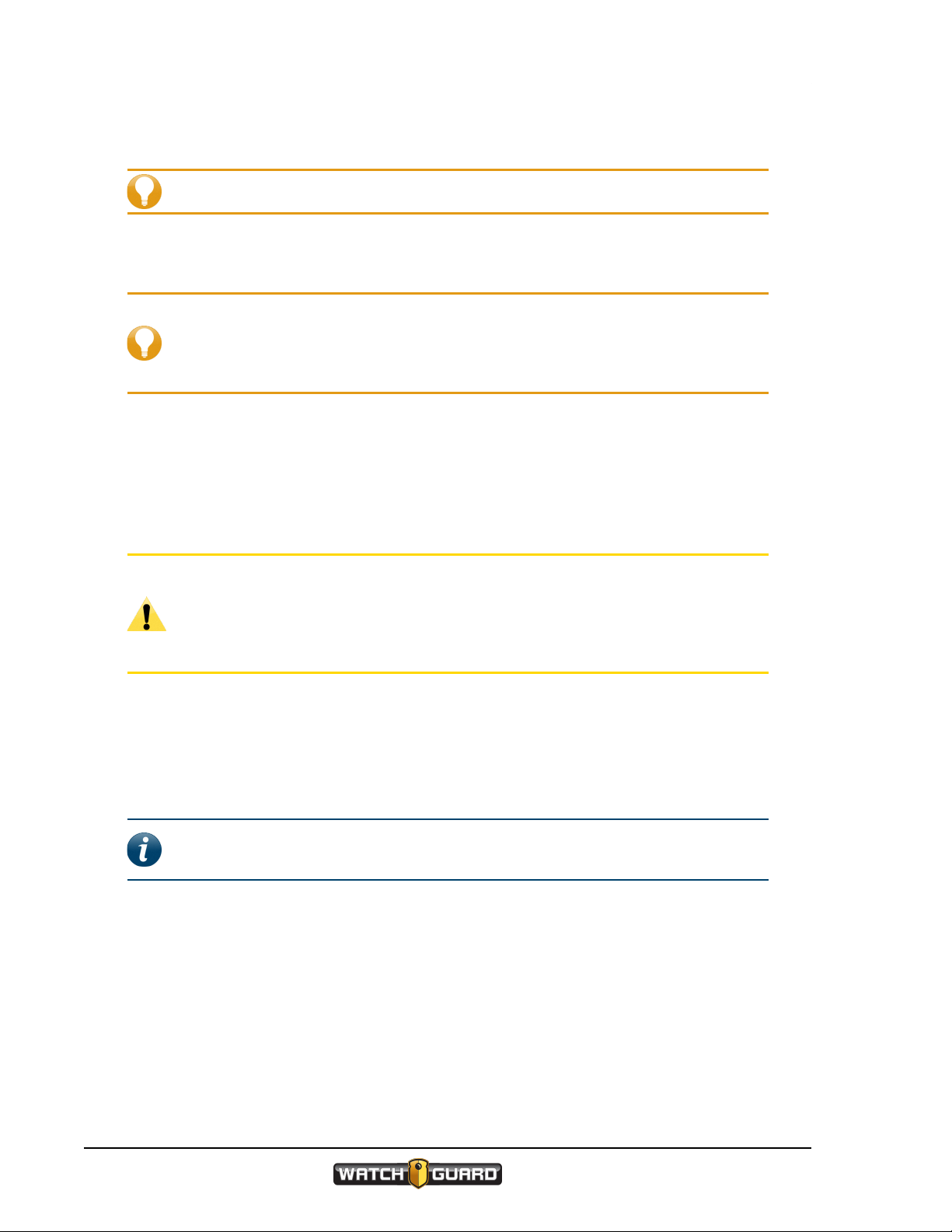
Wearing VISTA
The VISTA Wearable Camera has four main mounting options:
l Rotatable shirt clip (included with the standard battery version) (below)
l Duty belt clip (below)
l Locking chest mount (included with the extended battery version) (page 27)
Warning! The chest mount uses magnets to hold the VISTA camera in
place. Do not wear the chest mount near sensitive medical equipment or
implants such as pacemakers or other magnetically programmable
medical devices.
l MOLLE vest loop mount (page 28)
Wear VISTA on your clothing where it is most comfortable, convenient, and secure for you.
Make sure that the lens is not obstructed and that it is aimed at the horizon.
The quick mounting latch on VISTA attaches to any of the mounting options.
Using the rotatable shirt clip and duty belt clip
The rotatable clip mount uses a heavy-duty
alligator clip that rotates and slides to make it
more convenient for you to secure VISTA
where you want to wear it.
The belt clip mount uses an alligator clip with a hook at
the bottom to securely clip VISTA to your duty belt.
Both clips connect to VISTA the same way.
26
VISTA Wearable Camera
WGD00120 Revision E
Page 27
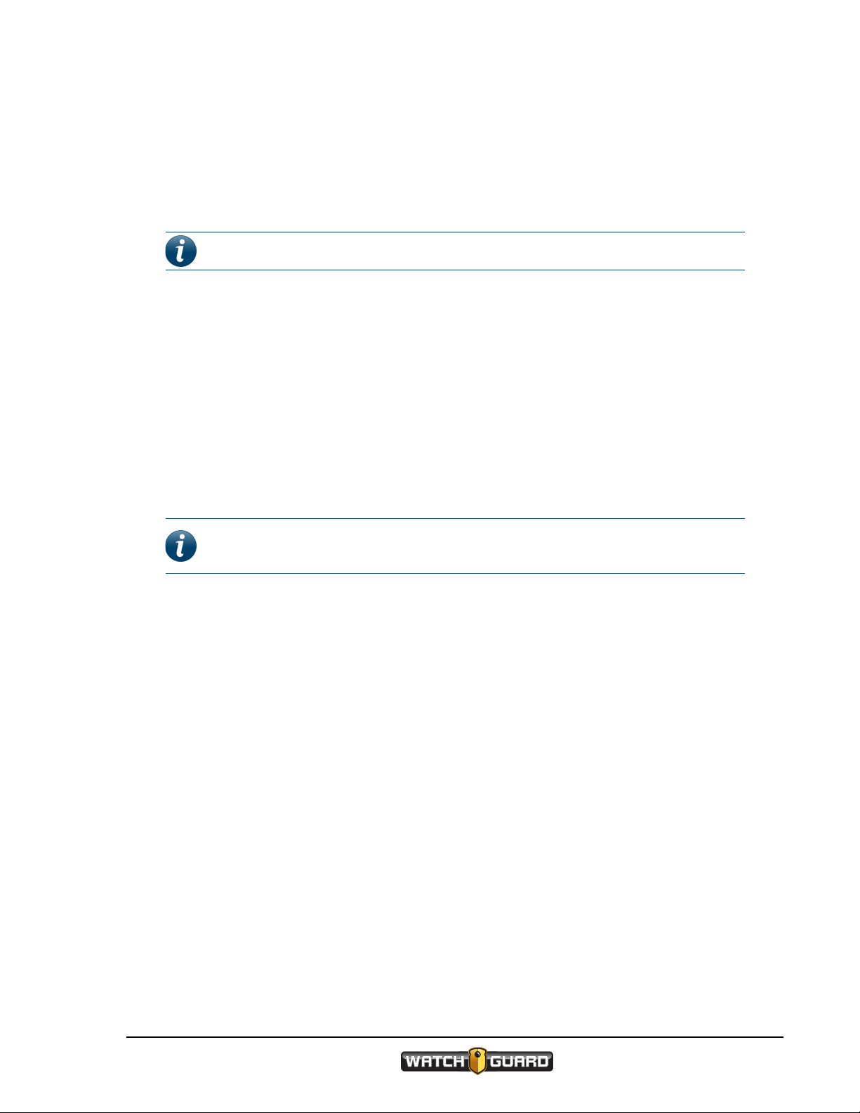
To connect VISTA to either clip:
1. Match the anchor tab on the back of the clip with the
slot on the back of VISTA.
2. Match the mounting tab on the clip with the quick
mounting latch on VISTA, then slide the latch over
the tab.
3. Attach the clip to your clothing or your belt where
you want to wear VISTA.
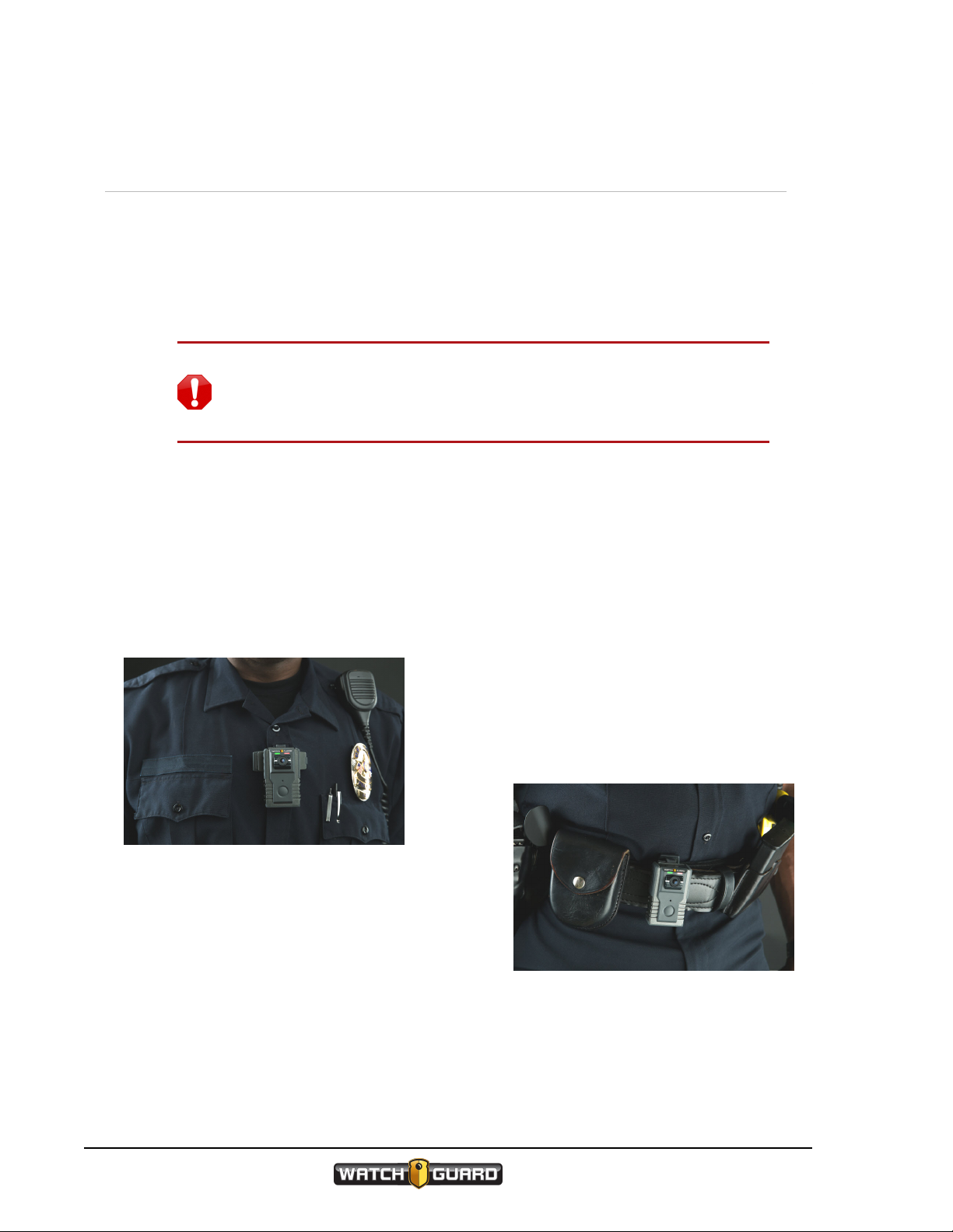
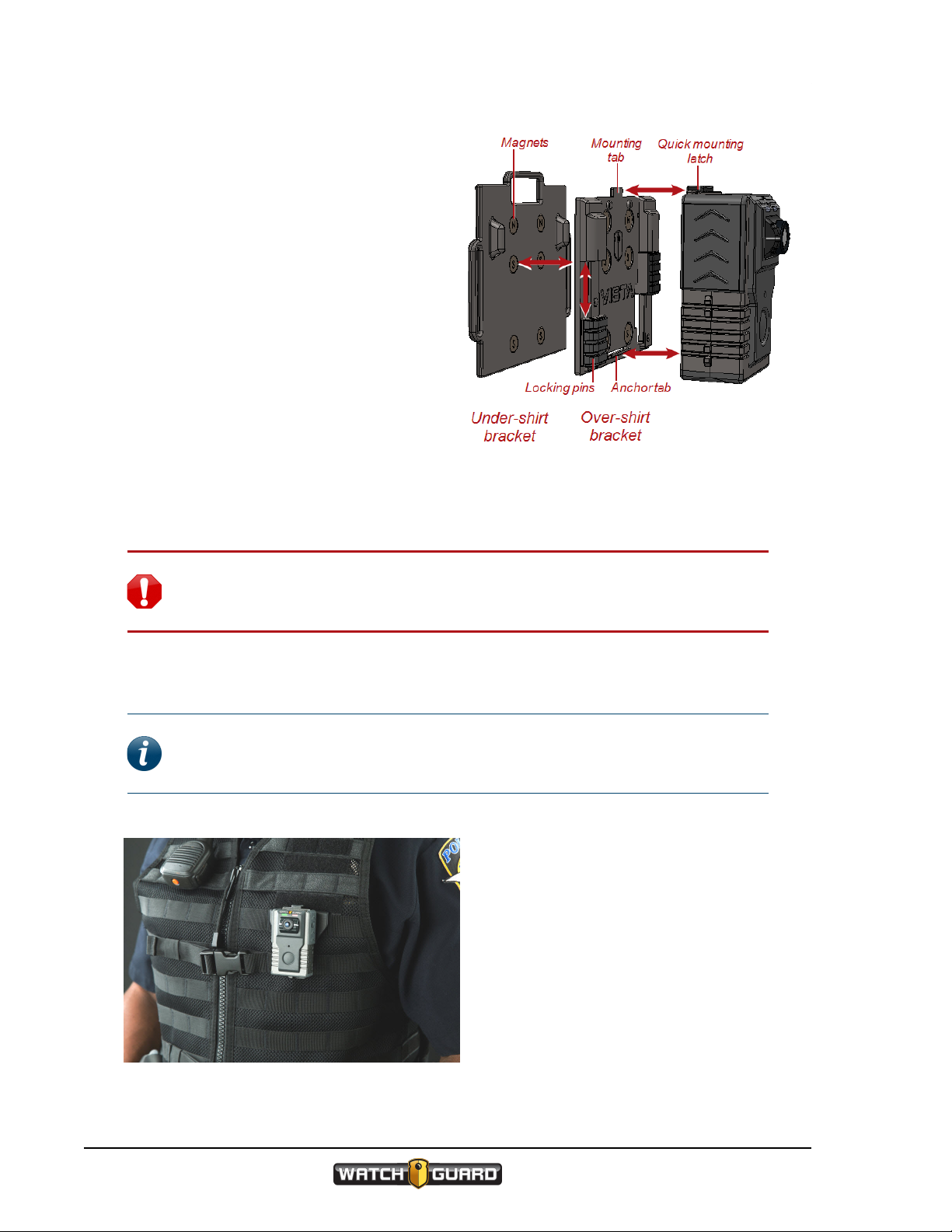
Using the locking chest mount
Warning! The chest mount uses magnets to hold the VISTA camera in place.
Do not wear the chest mount near sensitive medical equipment or implants such
as pacemakers or other magnetically programmable medical devices.
Using the locking chest mount
The chest mount uses magnets and
locking pins to secure the mount to
your clothing. When you wear the
chest mount, one bracket goes under
your shirt, the other goes over your
shirt.
Important! Because of the strength of the magnets, separating the brackets
requires some effort. Realigning the brackets causes them to snap together
forcefully.
VISTA Wearable Camera
WGD00120 Revision E
27
Page 28
Using VISTA
To use the chest mount:
1. Separate the under-shirt bracket from
the over-shirt bracket.
2. Match the anchor tab on the over-shirt
bracket with the slot on the back of
VISTA.
3. Match the mounting tab on the overshirt bracket with the quick mounting
latch on VISTA, then slide the latch over
the tab.
4. Place the under-shirt bracket under your
shirt where you want to wear VISTA.
5. Place the over-shirt bracket, with VISTA
attached, against the under-shirt
bracket, with your shirt between them.
The magnets on both brackets line up
automatically, securing the mount to
your shirt.
6. To lock the mount in place, slide both of the locking pins up into their safety housings.
Warning! The chest mount uses magnets to hold the VISTA camera in place.
Do not wear the chest mount near sensitive medical equipment or implants such
as pacemakers or other magnetically programmable medical devices.
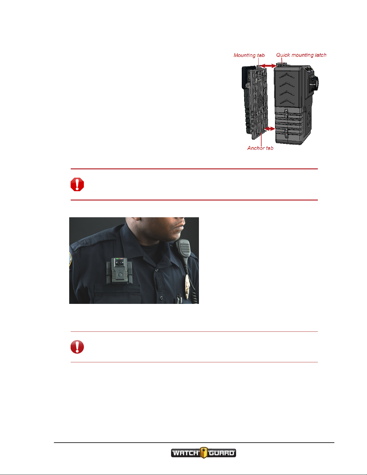
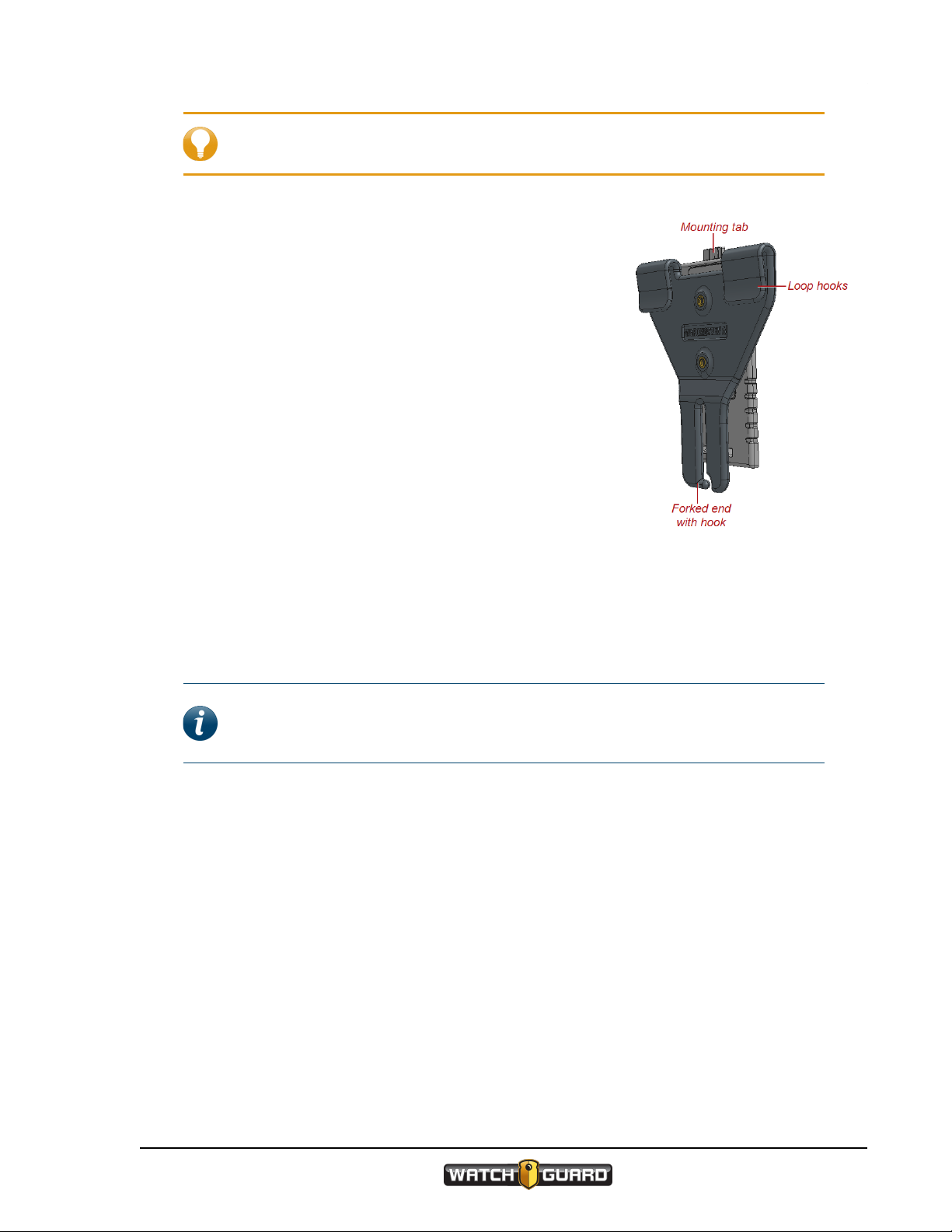
Using the MOLLE vest loop mount
Note: Some of the earliest versions of the VISTA Wearable Camera do not
connect to the MOLLE vest mount. Please consult with your WatchGuard Video
representative for more information.
The MOLLE vest mount uses hooks to
anchor VISTA over two rows of loops
on the MOLLE vest.
28
VISTA Wearable Camera
WGD00120 Revision E
Page 29
Tip: Install the mount on the MOLLE vest before you connect VISTA to the
mount.
To use the MOLLE vest mount with VISTA:
1. Determine which two rows of loops on the MOLLE vest
you want to use to mount the VISTA Wearable Camera.
2. On the lower of the two rows, slide the forked end down
over the sewn seam between two loops until the hook is
engaged below the seam.
You may need to slightly twist the mount to help the
hook slide over the seam.
3. Slightly fold the fabric between the two rows so that the
upper loop hooks engage two loops on the upper row of
loops.
4. Slide the upper loop hooks down over the two loops,
straightening the fabric between the rows, to fully seat
the mount.
Using the MOLLE vest loop mount
The forked end should be fully engaged with the seam on
the lower row of loops. The loop hooks should be fully
engaged with two loops on the upper row of loops.
5. Match the anchor tab on the bottom of the outward-facing plate of the MOLLE vest mount with
the bottom slot on the back of VISTA.
6. Match the mounting tab on the top of the mount with the quick mounting latch on VISTA,
then slide the latch over the tab.
Note: VISTA connects to the MOLLE vest mount in the same way it connects to
the shirt or belt clip. For more information, see Using the rotatable shirt clip and
duty belt clip on page 26.
VISTA Wearable Camera
WGD00120 Revision E
29
Page 30
Using VISTA
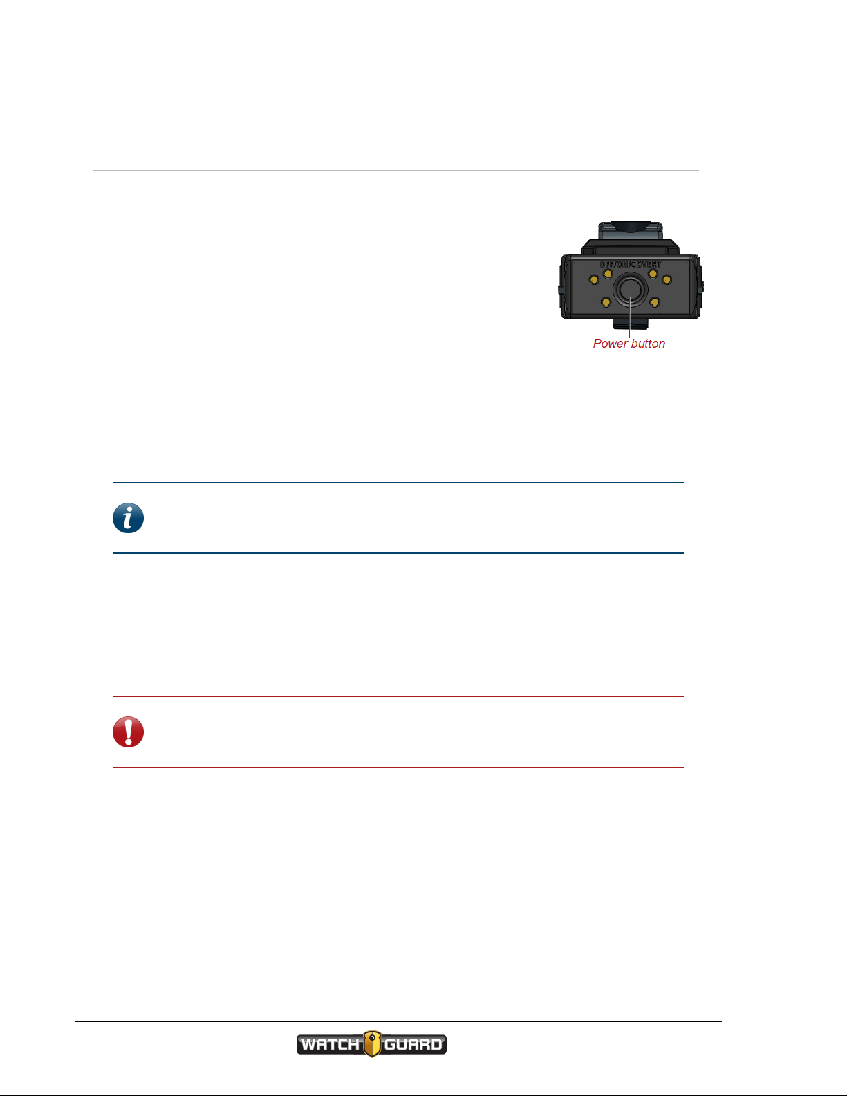
Powering On and Off
You use the Power button to power VISTA on and off. The Power
button is on the bottom of the VISTA Wearable Camera.
Powering on
To power VISTA on:
n With the power off, press and release the Power button.
VISTA goes through its booting sequence. When it is ready to use, the
LCD Display reads READY and the green LED lights steadily. Three
ascending tones sound (depending on your alert notification selections).
Powering off
Note: VISTA can be configured to power off automatically if it is left idle (no
movement and/or button presses) for a period of time. For more information, see
Automatic Off on page 61.
To power VISTA off:
n With the power on, press and release the Power button two times within 5 seconds.
After you press and release the Power button the first time, the LCDDisplay reads OFF? 2X
asking for confirmation that you want to power VISTA off. Pressing the Power button the
second time confirms to VISTA that you want to power it off.
Important! If you do not press the Power button the second time within 5
seconds, the LCD Display clears, and you will need to start the power off
sequence again.
Once you press the Power button the second time, the LCD Display scrolls SHUTTING
DOWN and the green LED turns off. Three descending tones sound (depending on your alert
notification selections).
30
VISTA Wearable Camera
WGD00120 Revision E
Page 31

Forcing power off
Forcing power off
In the rare case where VISTA stops responding to commands (or if WatchGuard Video Technical
Services instructs you to), you can force VISTA to power off.
Warning! Avoid forcing VISTA to power off, if at all possible. Forcing VISTA's
power off can, in rare cases, result in data corruption.
To force VISTA to power off:
n Press and hold the Power button until VISTA powers off, about 15 seconds.
Note: If you have forced VISTA's power off, WatchGuard Video recommends
that you dock VISTA in a USBBase as soon as it is feasible. Docking the camera in
a USB Base allows VISTA to repair itself.
Starting and Stopping a Recorded Event
Typically, you use the Record Start/Stop button to start or
stop a recorded event on the VISTA Wearable Camera. The
Record Start/Stop button is on the front of the VISTA camera.
If your VISTA WiFi is a member of a recording group,
VISTA WiFi can start or stop a recorded event automatically
when alerted by another group member that the other group
member has started or stopped an event. For more information
on recording groups, see VISTA WiFi: Using VISTAWiFi with a
Recording Group on page 63.
If your VISTA WiFi is connected to the VISTA
SmartConnect smartphone app, you can start or stop a
recorded event using SmartConnect. For more information on
using the smartphone app, see Starting and Stopping Recorded
Events Using SmartConnect on page 81.
Starting a recorded event manually
To manually start a recorded event on VISTA:
n Press the Record Start/Stop button.
The LCD Display shows the REC icon
(lREC) and the recording length, and the red LED lights steadily. Two ascending tones sound
with a vibration (depending on your alert notification selections).
VISTA Wearable Camera
WGD00120 Revision E
31
Page 32

Using VISTA
Note: A VISTA WiFi that has automatically started an event behaves in the
same way.
As the recorded event continues, the LCD Display shows the current recorded event length
increasing every second and the storage indicators updating as needed.
Stopping a recorded event manually
Note: VISTA can be configured to NOT allow manual event stop. If you cannot
manually stop the VISTA camera, when you press the Record Start/Stop
button, two low tones sound with a vibration (depending on your alert
notification selections) and the LCD Display reads IGNORED for 3 seconds.
To manually stop a recorded event on VISTA:
n Press the Record Start/Stop button.
Important! You may need to press the Record Start/Stop button a second
time within 5 seconds to confirm the event stop, depending on your VISTA
configuration.
The REC icon (lREC) turns off on the LCDDisplay and the red LED turns off. Two descending
tones sound with a vibration (depending on your alert notification selections).
Note: A VISTA WiFi that has automatically stopped an event behaves in the
same way.
After a recorded event has stopped, if event categorization is required as part of VISTA's
configuration, the event categorization sequence starts. For instructions how to categorize a
VISTA recorded event, see Categorizing a Recorded Event on page 34.
VISTA can be configured to stop a recorded event automatically after a period of time. For more
information, see Maximum Recorded Event Time on page 61.
Tip: Even if VISTA WiFi is NOT configured to require an event-stop confirmation
(second press of the Record Start/Stop button within 5 seconds), you need to
confirm an event stop in the following scenario:
VISTA WiFi automatically starts an event because a member of the local
recording group reports that it started a recorded event. You immediately (within
10 seconds) press the Record Start/Stop button to STOP the recorded event
because you do not want VISTA WiFi to record it. VISTA WiFi requests that you
press the Record Start/Stop button again to confirm that you want to STOP
the recorded event. If you do not press the button a second time within 5
seconds, VISTA WiFi continues to record the event.
32
VISTA Wearable Camera
WGD00120 Revision E
Page 33

Muting the Audio During a Recorded Event
Muting the Audio During a Recorded Event
Note: The ability to mute a VISTA Wearable Camera during a recorded event is
set up as part of a configuration in WatchGuard Video Evidence Library software.
You may or may not be able to mute your VISTA depending on the options
selected in the configuration assigned to your camera.
You can use the Display Backlight button on VISTA to mute the
audio during a recorded event. The Display Backlight button is on
the right side as you look at the front of VISTA.
If VISTA is configured to allow muting, when you press and hold
down the Display Backlight button during an event, VISTA mutes
the event audio. As long as you continue to hold the Display
Backlight button, the audio is muted. When you release the button,
the event audio continues normally.
Muting VISTA audio
To mute VISTA audio during a recorded event:
1. Press and hold down the Display Backlight button.
2. Continue to hold down the Display Backlight button as long as you want the event audio to
remain muted.
The LCD Display reads MUTED while you hold down the Display Backlight button.
VISTA audio unmutes when you release the Display Backlight button.
Tip: You cannot mute the audio while you are categorizing a recorded event on
VISTA. Selecting a category requires that you hold down the same button
(Display Backlight) you hold down for muting. Once you have finished
categorizing, you can again mute VISTA audio. For information on categorizing a
recorded event on VISTA, see Categorizing a Recorded Event on page 34.
VISTA Wearable Camera
WGD00120 Revision E
33
Page 34

Using VISTA
Categorizing a Recorded Event
Note: Event categorization is set up as part of a configuration in WatchGuard
Video Evidence Library software. You may or may not need to categorize a
recorded event depending on the configuration assigned to your VISTA Wearable
Camera.
You use the Display Backlight button on the VISTA Wearable
Camera to select a category to apply to a recorded event. The
Display Backlight button is on the right side as you look at the
front of VISTA.
If VISTA is configured to require categorization, when you stop an
event, the LCD Display immediately prompts you to select an event
category.
If your VISTA WiFi is a member of a recording group, VISTA
WiFi can automatically accept an event category from the 4RE DVR
group member as its own category. However, any category selected
directly on VISTA WiFi overrides the 4RE category. For more
information on recording groups, see VISTA WiFi: Using VISTAWiFi
with a Recording Group on page 63.
If your VISTA WiFi is connected to the VISTA SmartConnect smartphone app, you
can categorize an event using SmartConnect. Any category selected on SmartConnect
overrides a 4RE category. If you categorize an event on both the VISTA WiFi camera and the
smartphone app, the last selected category, regardless of the device, will be applied to the
event. For more information on using the smartphone app, see Categorizing Recorded Events
Using SmartConnect on page 78.
Categorizing a recorded event on VISTA
To categorize a recorded event:
1. Stop the event manually or allow VISTA WiFi to stop the event automatically.
The LCDDisplay shows the event categorization prompt (the prompt default is CATEGORY).
2. Press and release the Display Backlight button as many times as needed to move through
the list of available event categories, one at a time.
3. Press and hold the Display Backlight button for at least 2 seconds when the event category
you want to select shows on the LCD Display.
The LCD Display reads SAVED and shows you which category you selected. One long tone
sounds with a vibration (depending on your alert notification selections).
If another recorded event starts (manually or automatically) while VISTA is in the middle of the
event categorization sequence, VISTA aborts the sequence and starts the new event. You will
be able to categorize the recorded event later in your Evidence Library software, if necessary.
34
VISTA Wearable Camera
WGD00120 Revision E
Page 35

About VISTA
In this section...
l Video, audio, and subtitle evidence (page 36)
l Camera components (page 38)
l Available mounts (page 47)
l Function of the bases
o
USB Base (page 50)
o
VISTA Transfer Station (page 51)
o
VISTA WiFi Base (page 52)
About VISTA
VISTA Wearable Camera
WGD00120 Revision E
35
Page 36

About VISTA
Overview
The VISTA Wearable Camera:
l Captures, processes, and stores video and audio evidence (below)
l Functions as a camera and DVR (digital video recorder) combination (page 38)
l Includes mounts to help you wear it on your clothing (page 47)
l Comes with a USB Base for charging, provisioning, and uploading (page 50)
l Can be docked in a VISTA Transfer Station for charging, provisioning, and uploading (page 51)
l VISTA WiFi: Can be paired with a VISTA WiFi Base for charging, uploading, and associating with
a recording group (page 52)
Video, Audio, and Subtitle Evidence
The VISTA Wearable Camera works as a DVR and camera combination to collect evidence in the
form of recorded events. A recorded event is a unique, protected segment of recorded:
l Video (page 37)
l Audio (page 37)
l Subtitles (page 37)
When you press the Record Start/Stop button to start and then stop a recording, VISTA
protects the video/audio segment between the two button presses as a recorded event.
If your VISTA WiFi is a member of a recording group, VISTA WiFi can also start or stop
a recorded event automatically when alerted by another group member that the other group
member has started or stopped an event. VISTA WiFi protects the segment between the
automatic start and stop in the same way it protects the segment between the manual button
presses. Both protected segments are recorded events.
Note: Not all VISTA Wearable Cameras are VISTA WiFi cameras. If you are not
sure whether your equipment has the Wi-Fi® feature, contact your WatchGuard
Video representative.
Depending on the configuration applied to VISTA, the camera may be capturing video all the
time or only during a recorded event. If the camera is capturing video all the time (RecordAfter-the-Fact®(RATF) is enabled), only the protected segment (between the manual or
automatic start and stop) is considered a recorded event.
36
Tip: If VISTA is configured with RATF enabled, you may be able to use your
Evidence Library software to send a manual request to the camera to retrieve an
RATF event: video that was not originally part of a recorded event. For more
information about retrieving an RATF event from VISTA, see your Evidence
Library software user guide.
VISTA Wearable Camera
WGD00120 Revision E
Page 37

If VISTA is configured to enable pre-event video, a recorded event also includes that pre-event
time.
Normally, only recorded events are uploaded to your Evidence Library software.
Video
VISTA records one stream of video and compresses it using h.264 high-profile compression.
Depending on the configuration applied to VISTA, the video quality can be:
l High definition (HD), 720p, at a frame rate of 5, 10, 15, or 30 frames per second
or
l Standard definition (SD), 480p, at a frame rate of 5, 10, 15, or 30 frames per second
Audio
VISTA records CD quality audio with minimal distortion and wind noise. Depending on the
configuration applied to VISTA, the camera can:
l Continuously record audio (default setting)
or
Video
l Only record audio during recorded events
Subtitles
Subtitles are the text information that can be overlaid on the video. VISTA includes the
following subtitles:
l Officer name
l Date and time
l VISTA device ID
l Microphone on or off
l GPS location (VISTA WiFi only)
Tip: The subtitles are always included with the video and audio in a recorded
event, but using your Evidence Library software, you can turn them off or on, if
needed.
For more information about...
The VISTA RATF special feature, see Record-After-the-Fact® on page 58.
Pre-event video, see Pre-Event Capture on page 57.
Provisioning VISTAwith a configuration, see Provisioning on page 20.
Importing VISTA recorded events to Evidence Library software, see Uploading on page 21.
Recording groups, see VISTA WiFi: Using VISTAWiFi with a Recording Group on page 63.
VISTA Wearable Camera
WGD00120 Revision E
37
Page 38

About VISTA
Camera Components
The VISTA Wearable Camerafunctions as a camera and DVR (digital video recorder)
combination.
VISTA components include:
l Camera sensor and lens (page 39)
l Microphone (page 39)
l Buttons (page 39)
o
Power
o
Record Start/Stop
o
Display Backlight
l LCD Display (page 40)
l Feedback indicators (page 42)
o
Tones
o
Vibration
o
LEDs
l Storage (page 42)
l Battery (page 43)
l Wi-Fi (VISTA WiFi only) (page 44)
l GPS (VISTA WiFi only) (page 45)
l Quick mounting latch (page 43)
Note: Not all VISTA Wearable Cameras are VISTA WiFi cameras. If you are not
sure whether your equipment has the Wi-Fi feature, contact your WatchGuard
Video representative.
38
VISTA Wearable Camera
WGD00120 Revision E
Page 39

Camera sensor and lens
Camera sensor and lens
VISTA's camera sensor is an ultra-wide dynamic range (U-WDR) image sensor. This sensor:
l Maintains rich colors at all light levels
l Increases low-light sensitivity
The 130-degree wide-angle lens rotates vertically +/-20 degrees. WatchGuard Video
recommends that you position the lens aiming at the horizon.
Microphone
VISTA uses a digital microphone to record CD quality sound with minimal distortion and wind
noise.
Depending on the configuration applied to VISTA, the microphone:
l Continuously records audio (default setting)
or
l Only records audio when you press the Record Start/Stop button
You can mute the VISTA microphone, depending on VISTA's configuration, using the Display
Backlight button. For more information, see Muting the Audio During a Recorded Event on
page 33.
Buttons
VISTA has three buttons that control the camera's functionality:
l Power button
l Record Start/Stop button
l Display Backlight button
Power button
You use the Power button to power VISTA on or off as
well as place it in Covert Mode. The Power button is on
the bottom of the camera.
For instructions how to power VISTA on and off, see
Powering On and Off on page 30. For more information
about placing VISTA in Covert Mode, see Covert Mode on
page 62.
VISTA Wearable Camera
WGD00120 Revision E
39
Page 40

About VISTA
Record Start/Stop button
You use the Record Start/Stop button to start or
stop a recorded event on VISTA. The Record
Start/Stop button is on the front of the camera.
For instructions how to start and stop a recorded
event on VISTA, see Starting and Stopping a
Recorded Event on page 31.
Display Backlight button
You use the Display Backlight button for multiple functions, including:
l Turning on the backlight for VISTA's LCD Display
l Showing VISTA's status on the LCD Display
l Aborting the sequence of status information on the display
l Muting the audio during a recording (see Muting the Audio During a
Recorded Event on page 33)
l Selecting an event category to assign to a recording (see Categorizing a
Recorded Event on page 34)
l Turning on VISTA WiFi's access point (hotspot) for the SmartConnect
smartphone application (see Appendix A: Using VISTA SmartConnect on
page 71)
l Canceling the sleep warning period (see Sleep Power State on page 60)
l Canceling the maximum recording time warning period (see Maximum
Recorded Event Time on page 61)
The Display Backlight button is on the right side as you look at the front of
the camera.
LCD Display
The LCD Display shows a number of icons and messages to indicate the status of the camera.
The icons show in the top half of the display; the messages show in the 8-character area on the
bottom half of the display. If a message is longer than 8 characters, the message scrolls. The
LCD Display is on the top of the camera.
40
VISTA Wearable Camera
WGD00120 Revision E
Page 41

The LCDDisplay informs you of:
l Assigned officer name
l Available event categories
Each category shows in the 8-character area as
you cycle through the list, for example,
DOMESTIC. If the item is longer than 8
characters, the item scrolls. The list of categories is
configured in your Evidence Library software (see
Categorizing a Recorded Event on page 34).
l Battery status
As the charge level decreases, the number of bars
in the Battery Charge icon decreases (see Battery
on page 43).
l Current date and time
The date shows as an abbreviation for the month
with a 1- or 2-digit day of the month, for example,
NOV 3.
l Current recording length
LCD Display
The recording length shows in the form HH:MM:SS,
for example, 1:23:59, and includes any configured
pre-event time (see Pre-Event Capture on page 57).
l Number of recorded events in storage
l Recording status
The REC icon (lREC) shows whether VISTA is currently recording.
l Saved storage total
The saved storage total shows as a decimal value in GB, for example, 11.07 GB.
l Storage status
As VISTA storage fills, the Storage Used meter fills with bars and the Storage Percentage
increases (see Storage on page 42).
l Upload status, if docked in the VISTA Transfer Station or the VISTA WiFi Base
The upload status shows the number of events uploaded out of the total number of events to
upload (see Uploading on page 21).
l Wi-Fi or GPS signal status (VISTA WiFi only)
Most of the time, the Wi-Fi Signal Strength icon shows the status of VISTA WiFi's Wi-Fi
connection with the WiFi Base (see VISTA WiFi: About the VISTA WiFi Base on page 52).
During the status information sequence (shows on the LCD Display when you press the
Display Backlight button), the Wi-Fi Signal Strength icon shows the status of the GPS
signal (see GPS signal status on page 45).
When VISTA is not recording, the default message shown on the LCD Display is the number of
recorded events in storage. When VISTA is not recording, but it is in Covert Mode, the default
shown on the display is COVERT. When the camera is recording, the default shown is the
current recording length.
VISTA Wearable Camera
WGD00120 Revision E
41
Page 42

About VISTA
Feedback indicators
Apart from the LCD Display, VISTA can also provide feedback on its status using:
l Tones
l Vibration
l Red and green LEDs
All of these feedback indicators are configurable in your Evidence Library software. You can set
up the tones and vibration to alert with:
l Tone only
l Vibration only
l Tone and vibration together
l No tone or vibration
You can configure the brightness level of the LEDs or set them to adjust automatically
depending on the time of day.
Note: If you place VISTA in Covert Mode, no tones sound and the LEDs do not
light. For information about placing the camera in Covert Mode, see Covert Mode
on page 62.
Storage
The VISTA Wearable Camera can store about 10 hours of the highest quality HD (high
definition) video.
VISTA's LCDDisplay shows a Storage Used meter and a Storage Percentage to
indicate how much of the storage has been used for protected video/audio
(recorded events). As VISTA records events and its storage fills, the Storage Used
meter fills with bars and the Storage Percentage number increases. For
information about protected video/audio, see Video, Audio, and Subtitle Evidence on page 36.
When the meter shows bars, video evidence has been saved in storage. The Storage
Percentage number shows the corresponding percentage of storage used.
When the Storage Used meter shows all ten bars, storage is more than 90
percent full (the Storage Percentage number will show 91% or higher). You
should dock VISTA to import video to your Evidence Library software as soon as
possible.
VISTA offers some special features to help you conserve storage space. For more information,
see Battery and storage saving special features on page 56.
When VISTA is about 10 minutes away from running out of storage space, the camera alerts
you with:
l Two short tones and/or a vibration (depending on VISTA's alert configuration settings)
l Slow-blinking red LED and Storage Used meter on the LCD Display
42
VISTA Wearable Camera
WGD00120 Revision E
Page 43

Battery
When VISTA storage is full, the camera alerts you again with an error condition alert:
l Fast-blinking red LED
l Three short tones and/or a vibration (depending on VISTA's alert configuration settings)
l Error message on the LCD Display
Warning! If storage fills completely, VISTA stops recording new video.
To free up storage space on VISTA, you must upload recorded events from VISTA to your
Evidence Library software. For information about uploading events to Evidence Library, see
Uploading on page 21.
Battery
The VISTA Wearable Camera uses a lithium-polymer (LiPo) battery. The battery charges in 3 to
5 hours when docked in a VISTA USB Base connected to an electrical outlet or in a VISTA
Transfer Station.
Caution: Some computers can be damaged when the USB Base is plugged into
an electrical outlet for power then directly into the computer using the USB cable.
To prevent this from happening, connect the USB Base to the computer through
the approved USB hub (Sabrent 7-Port USB 2.0 Hub, WatchGuard Video part
number WGP02364).
Tip: WatchGuard Video recommends that you use the USB Base or the Transfer
Station inside your agency when fully charging the VISTA battery. Charging in a
vehicle base can impact the vehicle battery and can slow down significantly in
warmer temperatures.
VISTA is available in two battery versions:
l Standard capacity battery
VISTA with the standard capacity battery weighs 4.3 ounces and can continuously record the
highest HD (high definition) quality video for about 6 hours.
l Extended capacity battery
VISTA with the extended capacity battery weighs 5.3 ounces and can continuously record the
highest HD quality video for about 9 hours.
Important! VISTA WiFi is ONLYavailable with the extended capacity battery.
VISTA's LCD Display shows a Battery Charge icon that indicates the charge level of the
battery. When the icon shows the battery with all five bars, the battery is fully charged.
When the icon shows less then five bars, the charge level of the battery is less than fully
charged.
VISTA Wearable Camera
WGD00120 Revision E
43
Page 44

About VISTA
When the Battery Charge icon shows only the outline, the battery charge is less than 10
percent; in this case, you should dock VISTA to charge as soon as possible. For instructions
how to charge the VISTA battery, see Charging on page 24.
When VISTA has nearly run out of battery power (less than 5 percent of full capacity
remaining), the camera alerts you with:
l Two tones and/or a vibration (depending on VISTA's alert configuration settings)
l Slow-blinking red LED and Battery Charge icon on the LCD Display
VISTA offers a number of special features to help you conserve battery power. For more
information, see Battery and storage saving special features on page 56.
LOW BATT message
The LOW BATT message appears on the VISTA LCDDisplay when you push the Power button
to power the camera up, but the battery charge level is so low that VISTA cannot successfully
power up. You should dock VISTA to charge as soon as possible.
LOW BASE message
The LOWBASEmessage appears on the VISTA LCDDisplay when VISTA is docked in a
USBBase, but the base is not providing enough power to charge the camera.
VISTA can charge in a USB Base connected to the USBport on a computer, depending on the
voltage provided by the USB port. The camera charges significantly faster when docked in a USB
Base plugged into an electrical outlet or in a VISTA Transfer Station.
Caution: Some computers can be damaged when the USB Base is plugged into
an electrical outlet for power then directly into the computer using the USB cable.
To prevent this from happening, connect the USB Base to the computer through
the approved USB hub (Sabrent 7-Port USB 2.0 Hub, WatchGuard Video part
number WGP02364).
VISTA WiFi: Wi-Fi
Note: Not all VISTA Wearable Cameras or VISTA bases have the Wi-Fi® feature.
If you are not sure whether your equipment has the Wi-Fi feature, contact your
WatchGuard Video representative.
The VISTA WiFi Wearable Camera adds built-in Wi-Fi (802.11n) to the existing VISTA Wearable
Camera.
Note: VISTA WiFi also adds GPS to the existing VISTA feature set. For more
information, see VISTA WiFi: GPS on page 45.
44
VISTA Wearable Camera
WGD00120 Revision E
Page 45

VISTA WiFi: GPS
The Wi-Fi feature allows VISTA WiFi to pair with the WiFi Base. Once the camera and the base
are paired, VISTA WiFi is associated with the local recording group. For more information about
pairing VISTA WiFi with the WiFi Base, see VISTA WiFi: Associating with a recording group on
page 25.
When VISTA WiFi is paired with the base, the camera LCD Display shows a Wi-Fi
Signal Strength icon that indicates the strength of the Wi-Fi signal coming from the
WiFi Base.
Because of the Wi-Fi feature, VISTA WiFi can also operate as a Wi-Fi access point
(hotspot) for the VISTA SmartConnect smartphone application. For more information on
connecting SmartConnect with VISTA WiFi, see Appendix A: Using VISTA SmartConnect on
page 71.
For more information about...
Recording groups, see VISTA WiFi: Using VISTAWiFi with a Recording Group on page 63.
VISTA WiFi: GPS
The VISTA WiFi Wearable Camera adds built-in GPS (Global Positioning System) to the existing
VISTA Wearable Camera.
Note: VISTA WiFi also adds Wi-Fi to the existing VISTA feature set. For more
information, see VISTA WiFi: Wi-Fi on page 44.
VISTA WiFi uses the GPS feature to apply:
l Accurate timestamps to recorded events
These timestamps allow your Evidence Library software to synchronize playback between
events (video and/or audio) from VISTA WiFi cameras and/or 4RE DVRs.
l GPS location coordinates to VISTA WiFi recorded events
Both the timestamps and the location coordinates are included in the subtitles during playback
in your Evidence Library software.
When the VISTA WiFi GPS finds its first fix, the camera LCD Display shows GPS Lock for 5
seconds.
Note: The GPS feature can be disabled for VISTA WiFi in your Evidence Library
software configuration, if you need to conserve power.
GPS signal status
If GPS is enabled on VISTA WiFi, you can see the status of a VISTA WiFi's GPS signal during the
status information sequence. The information sequence shows on the LCD Display when you
press the Display Backlight button.
VISTA Wearable Camera
WGD00120 Revision E
45
Page 46

About VISTA
During the information sequence, VISTA WiFi uses the bars of the Wi-Fi Signal Strength icon
to communicate the camera's GPS lock status:
l 0 bars: GPS has never locked since the camera's last reboot
l 1 bar: GPS has locked at least one time since the camera's last reboot, but is NOT currently
locked
l 5 bars: GPS is actively locked
Quick mounting latch
The quick mounting latch on VISTA attaches to the mounting
tab on any of the mount options; slide the latch over the tab on
the mount to attach or release VISTA.
For more information about mounting options and wearing
VISTA, see Available Mounts on page 47.
46
VISTA Wearable Camera
WGD00120 Revision E
Page 47

Available Mounts
Available Mounts
WatchGuard Video offers multiple mounting options for the VISTA Wearable Camera. The
following mounts are the most common:
l Rotatable shirt clip (below)
l Locking chest mount (page 48)
Warning! The chest mount uses magnets to hold the VISTA camera in
place. Do not wear the chest mount near sensitive medical equipment or
implants such as pacemakers or other magnetically programmable
medical devices.
l Duty belt clip (page 48)
l MOLLE vest loop mount (page 49)
The quick mounting latch (page 46) on VISTA attaches to the mounting tab on any of the
mounts.
Wear VISTA on your clothing where it is most comfortable, convenient, and secure for you.
Make sure that the lens is not obstructed and that it is aimed at the horizon.
Rotatable shirt clip
The rotatable clip mount uses a heavy-duty alligator clip that
rotates to make it more convenient for you to secure VISTA
where you want to wear it.
For instructions how to connect the rotatable clip to your
clothing, see Using the rotatable shirt clip and duty belt clip
on page 26.
VISTA Wearable Camera
WGD00120 Revision E
47
Page 48

About VISTA
Locking chest mount
Warning! The chest mount uses magnets to hold the VISTA camera in place.
Do not wear the chest mount near sensitive medical equipment or implants such
as pacemakers or other magnetically programmable medical devices.
The chest mount uses magnets
and locking pins to secure the
mount to your clothing. When you
wear the chest mount, one
bracket goes under your shirt, the
other goes over your shirt.
For instructions how to connect
the magnetic chest mount to your
clothing, see Using the locking
chest mount on page 27.
48
Duty belt clip
The belt clip mount uses the combination of an alligator clip
with a hook at the bottom to securely clip VISTA to your duty
belt.
Important! Make sure that VISTA's lens is not
obstructed if it is clipped to your belt; you should
aim the lens at the horizon.
For instructions how to connect the belt clip to your clothing,
see Using the rotatable shirt clip and duty belt clip on page
26.
VISTA Wearable Camera
WGD00120 Revision E
Page 49

MOLLE vest loop mount
MOLLE vest loop mount
The MOLLE vest mount uses hooks to anchor VISTA
to loops on the MOLLE vest.
For instructions how to connect the MOLLE vest loop
mount to your clothing, see Using the MOLLE vest
loop mount on page 28.
Other mounts
Other mount options include:
l VELCRO® plate mount: Works with externally-worn vests with VELCRO surfaces
l Klick Fast mount: Works with UK-style Klick Fast receivers
l Tripod mount: Works on standard mounts with 1/4″-20 threads
l RAM® mount: Includes a 1-inch ball for RAM accessories
Contact your WatchGuard Video representative for information.
VISTA Wearable Camera
WGD00120 Revision E
49
Page 50

About VISTA
About the USB Base
The VISTA Wearable Camera can use the USB Base for charging as
well as interacting with Evidence Library software for:
l Uploading evidence
l Provisioning
l Updating firmware
l Defining a Record-After-the-Fact
l Requesting a state capture for troubleshooting
®
(RATF) event
The heavy-duty USB Base has connections for both a
power cable and a USB cable. For instructions how to set
up the VISTA USB Base, see Setting up the VISTA USB
Base below.
When you dock VISTA in its USB Base, it automatically
starts charging, if needed, and initiates an evidence
upload, if applicable.
For more information about using VISTA with the USB
Base, see Docking VISTA in a USB Base on page 15.
Setting up the VISTA USB Base
To set up the USB Base to use with a VISTA Wearable Camera and your Evidence Library
software:
Caution: Some computers can be damaged when the USB Base is plugged into
an electrical outlet for power then directly into the computer using the USB cable.
To prevent this from happening, connect the USB Base to the computer through
the approved USB hub (Sabrent 7-Port USB 2.0 Hub, WatchGuard Video part
number WGP02364).
1. Set up the approved USB hub and connect it to the computer where your Evidence Library
software is located.
2. Plug the power cable for the USB Base into an electrical outlet.
3. Connect the power cable to the USBBase.
4. Connect the USB cable to the USBBase and then into the approved USB hub.
50
VISTA Wearable Camera
WGD00120 Revision E
Page 51

About the VISTA Transfer Station
About the VISTA Transfer Station
The VISTA Wearable Camera can use the VISTA Transfer Station for charging as well as
interacting with Evidence Library software for:
l Uploading evidence
l Provisioning
l Updating firmware automatically
The VISTA Transfer Station allows your agency's Evidence Library software to interact with
multiple VISTA cameras simultaneously. You can connect multiple Transfer Stations to one
instance of Evidence Library software.
Each Transfer Station has eight slots for VISTA cameras.
Three LEDs on the Transfer Station
show power and connection status:
l Green, left position: When lit,
indicates that the Transfer
Station is powered on
l Amber, center position:
When lit, indicates that the
Transfer Station is connected to
Evidence Library software;
when blinking, indicates data is
being transferred
l Red, right position: When lit,
indicates an error condition
The Transfer Station has connections
for both a power cable and an Ethernet cable. You power the Transfer Station off and on using
the power switch.
When you dock VISTA in a Transfer Station, it automatically starts charging, if needed, and
initiates an evidence upload, if applicable.
VISTA Wearable Camera
WGD00120 Revision E
51
Page 52

About VISTA
For more information about using VISTA with the Transfer Station, see Docking VISTA in a
VISTA Transfer Station on page 17.
Setting up the VISTA Transfer Station
For instructions how to set up the VISTA Transfer Station, see Appendix B: VISTA Transfer
Station Setup on page 85.
VISTA WiFi: About the VISTA WiFi Base
Note: Not all VISTA Wearable Cameras or VISTA bases have the Wi-Fi® feature.
If you are not sure whether your equipment has the Wi-Fi feature, contact your
WatchGuard Video representative.
The VISTA WiFi Wearable Camera can use the
VISTA WiFi Base to
l Associate with a local recording group
The WiFi Base acts as the Wi-Fi access point
(802.11n hotspot) for VISTA WiFi to
connect to the local recording group
network. The WiFi Base broadcasts over an
approximate range of 300 feet, line-ofsight.
l Update the camera's firmware
l Upload recorded events from the camera's
storage (only with an Evidence Library 4
Web connection)
l Charge the camera's battery
You should only use the WiFi Base for incidental charging during your shift. Charging in a
vehicle base can impact the vehicle battery and can slow down significantly in warmer
temperatures.
Tip: Use the USB Base or the Transfer Station inside your agency when fully
charging the VISTA battery.
52
VISTA Wearable Camera
WGD00120 Revision E
Page 53

VISTA WiFi: About the VISTA WiFi Base
Two bi-color LEDs on the front of the WiFi Base show power and connection status. The left
LEDis either red or green.
Left LED (red/green)
LED state VISTAWiFi Base state
Off Powered off
Red Undefined
Green Powered on
Blinking red Error condition
Blinking green In shutdown or wireless upload timeout
period
The left LED on the WiFi Base blinks green three times when it successfully pairs with a VISTA
WiFi camera. The left LED blinks red three times if the pairing was not successful.
The right LED is either green or amber.
Right LED (green/amber)
LED state VISTA WiFi docked state VISTAWiFi Base state
Off --- Not connected to VISTA WiFi or
upload server
Amber Docked Connected to upload server
Green Not docked Connected to VISTA WiFi (Wi-
Fi connection)
Blinking amber Docked Activity with upload server
Blinking green Not docked Activity with VISTAWiFi (Wi-Fi
connection)
If two VISTA WiFi cameras are paired with the same VISTA WiFi Base, and one is docked, the
WiFi Base LEDs show the state of the DOCKED camera and WiFi Base pair.
The WiFi Base has connections for a Wi-Fi antenna
cable and a WatchGuard-provided custom power/data
cable on the back.
The WiFi Base power/data cable must connect to the
Smart Power Switch. For more information about the
WiFi Base as part of the local recording group network,
see VISTA WiFi: Using VISTAWiFi with a Recording
Group on page 63.
VISTA Wearable Camera
WGD00120 Revision E
When you dock VISTA WiFi in the WiFi Base, the
camera pairs with the base. VISTA WiFi begins to
charge, if needed, and initiates an evidence upload, if
applicable.
53
Page 54

About VISTA
Once VISTA WiFi is paired with the WiFi Base, VISTA WiFi is associated with the local recording
group that includes the WiFi Base.
For more information about using VISTA WiFi with the WiFi Base, see VISTA WiFi: Docking
VISTA WiFi in a VISTA WiFi Base on page 18.
Setting up the VISTA WiFi Base
Typically, the VISTA WiFi Base, its windshield antenna, and the Smart Power Switch are
installed in the vehicle by your agency's installation technicians. For more information about
installing the VISTA WiFi system equipment in the vehicle, see the 4RE Vehicle Installation
Instructions.
54
VISTA Wearable Camera
WGD00120 Revision E
Page 55

VISTASpecial Features
In this section...
l Pre-Event Capture (page 57)
l Record-After-the-Fact
l Force Microphone On (page 59)
l Sleep power state (page 60)
l Automatic Off (page 61)
l Maximum Recorded Event Time (page 61)
l Recording Reminder Alert (page 62)
l Covert Mode (page 62)
®
(page 58)
VISTASpecial Features
VISTA Wearable Camera
WGD00120 Revision E
55
Page 56

VISTASpecial Features
Overview
The VISTA Wearable Camera has a number of special features that give you more recording
options and can help you save battery power and storage. VISTA also has a Covert Mode that
turns off the camera tones and LEDs.
Recording special features
VISTA has the following special features related to recording:
l Pre-Event Capture: Enable this feature to allow VISTA to capture and save up to two minutes
of additional video prior to a recorded-event start (page 57)
l Record-After-the-Fact
save video that can generate a Record-After-the-Fact (RATF) event (page 58)
l Force Microphone On: Enable this feature to allow VISTA to capture audio whenever it is
capturing and saving video (page 59)
®
: Enable this feature to allow VISTA to continuously capture and
Note: All of the recording special features are configured in your Evidence
Library software.
Battery and storage saving special features
VISTA has the following special features related to saving battery power and storage space:
l Sleep power state: Enable this feature to allow VISTA to enter a low power state after a
period of time with no activity (page 60)
This feature can help save battery power.
l Automatic Off: Enable this feature to allow VISTA to turn itself off after a period of time with
no activity (page 61)
This feature can help save battery power.
l Maximum Recorded Event Time: Enable this feature to allow VISTA to automatically stop a
recorded event when it reaches a specified duration (page 61)
This feature can help save storage space.
l Recording Reminder Alert: Enable this feature to allow VISTA to notify you at regular
intervals that it is still capturing a recorded event (page 62)
This feature can help save storage space.
56
Note: All of the battery and storage saving special features are configured in
your Evidence Library software.
VISTA Wearable Camera
WGD00120 Revision E
Page 57

Covert Mode
Covert Mode
With Covert Mode enabled, VISTA sounds no tones, lights no LEDs, and only lights the Display
Backlight on demand. For instructions how to enable Covert Mode on VISTA, see Covert Mode
on page 62.
Pre-Event Capture
The Pre-Event Capture feature on the VISTA Wearable Camera allows you to capture and save
up to two minutes of additional video prior to a recorded-event start. You configure the PreEvent Capture feature in your Evidence Library software.
If the Pre-Event Capture feature is enabled, VISTA is continuously capturing and saving video
whenever it is powered on and not asleep. When an event is started, manually or
automatically, up to two minutes of that saved video is added to the recorded event prior to the
event start time.
Note: VISTA WiFi can start a recorded event automatically when associated with
a recording group. For more information about starting events, see Starting and
Stopping a Recorded Event on page 31.
For example, you start a recorded event (by pressing Record Start/Stop) at 2:15 PM and stop
it (again pressing Record Start/Stop) at 2:35 PM. With a Pre-Event Capture time configured
for one minute, the recorded event includes video recorded from 2:14 PM to 2:35 PM.
For the Pre-Event Capture feature, in your Evidence Library software, you configure how much
pre-event time you want captured, from none up to two minutes.
Audio
Audio is NOT typically included with pre-event video. Typically, VISTA only begins to record
audio when you start a recorded event.
You can include audio whenever VISTA is recording if you enable the Force Microphone On
feature. For information about this feature, see Force Microphone On on page 59.
For more information about...
Recorded events, see Video, Audio, and Subtitle Evidence on page 36.
Recording groups, see VISTA WiFi: Using VISTAWiFi with a Recording Group on page 63.
VISTA Wearable Camera
WGD00120 Revision E
57
Page 58

VISTASpecial Features
®
Record-After-the-Fact
The Record-After-the-Fact (RATF) feature on the VISTA Wearable Camera allows you to
continuously capture and save video you can use to generate an RATF event. You enable the
RATF feature in your Evidence Library software.
VISTA works as a DVR and camera combination to collect evidence in the form of recorded
events. When a recording is started and then stopped, automatically or manually, VISTA
protects the segment between the recording start and stop as a recorded event.
Note: VISTA WiFi can start and stop a recorded event automatically when
associated with a recording group. For more information about starting and
stopping events, see Starting and Stopping a Recorded Event on page 31.
When you enable the RATF feature on VISTA, the camera captures and stores video whenever
it is powered on and not asleep; however, only the protected segment between the event start
and stop (automatic or manual) is considered a recorded event. Typically, only recorded events
are uploaded to your Evidence Library software.
For the RATF feature, in your Evidence Library software, you configure whether you want
VISTA to continuously capture and save video or not.
Generating an RATF event
If VISTA has the RATF feature enabled, you can use your Evidence Library software to send a
manual request to the camera to generate and retrieve an RATF event. An RATF event typically
consists of video that was not originally part of a recorded event. For more information about
generating and retrieving an RATF event from VISTA, see your Evidence Library software user
guide.
Note: The Evidence Library software can only send an RATF event request to a
VISTA docked in the USBbase.
Storage
When RATF is enabled, VISTA overwrites the oldest unprotected (non-recorded event) area in
storage with any newly captured video or recorded events. This process can continue until
VISTA storage is filled with recorded events (protected recordings). Then you must upload
recorded events to your Evidence Library software to free up storage space before you can
continue to use VISTA.
58
VISTA Wearable Camera
WGD00120 Revision E
Page 59

Audio
Audio is NOT typically included in the saved video when RATF is enabled. Typically, VISTA only
begins to record audio when a recorded event is started. This means that audio is NOT typically
included with RATF video that was not originally part of a recorded event (protected recording).
You can include audio whenever VISTA is capturing and saving video if you enable the Force
Microphone On feature. For information about this feature, see Force Microphone On below.
For more information about...
Recorded events, see Video, Audio, and Subtitle Evidence on page 36.
Recording groups, see VISTA WiFi: Using VISTAWiFi with a Recording Group on page 63.
Force Microphone On
The Force Microphone On feature of the VISTA Wearable Camera allows you to capture audio
whenever the camera is capturing and saving video. You enable the Force Microphone On
feature in your Evidence Library software.
Audio
Typically, audio is only captured during a recorded event. This means that even though VISTA
may be configured to capture video all the time, if a recorded event is not started, automatically
or manually, VISTAdoes not record audio. (Audio is NOT typically included in pre-event video or
Record-After-the-Fact®(RATF) events.)
Note: VISTA WiFi can start and stop a recorded event automatically when
associated with a recording group. For more information about starting and
stopping events, see Starting and Stopping a Recorded Event on page 31.
When you enable the Force Microphone On feature, VISTA captures audio with the video
whenever it is capturing and saving video. This means that audio IS included with both preevent video and RATF events.
For the Force Microphone On feature, in your Evidence Library software, you configure whether
you want VISTA to capture audio whenever it is capturing and saving video or not.
For more information about...
Recorded events, see Video, Audio, and Subtitle Evidence on page 36.
Pre-event video, see Pre-Event Capture on page 57.
RATF events, see Record-After-the-Fact® on page 58.
Recording groups, see VISTA WiFi: Using VISTAWiFi with a Recording Group on page 63.
VISTA Wearable Camera
WGD00120 Revision E
59
Page 60

VISTASpecial Features
Sleep Power State
The Sleep power state on the VISTA Wearable Camera allows the camera to go into a low-power
state designed to help you conserve battery power. You configure the Sleep state in your
Evidence Library software.
When VISTA is configured for Sleep state, after a period of time with no movement and/or
button presses, VISTA enters a low power state where it cannot capture any video or audio.
From Sleep state, VISTA is ready to record in approximately 1 second.
The Sleep power state provides a significant reduction in power consumption. Starting with a
fully charged battery, VISTA can remain in its Sleep power state for more than 30 hours before
powering off due to a discharged battery.
For Sleep state, in your Evidence Library software you configure:
l Whether VISTA will sleep or not
l What makes VISTA sleep (lack of movement and/or button presses)
l How much time must elapse with no activity before VISTA goes to sleep
When VISTA is asleep, the LCD Display reads SLEEP and the green LED blinks slowly. The
display continues to show battery and storage status indicators.
Sleep warning period
About 15 seconds before it goes to sleep, VISTA warns you that it is about to go into Sleep
state:
l Five descending tones sound with vibration (depending on the configured alert notification
options)
l SLEEP blinks on the LCD Display
You can press the Display Backlight button or the Record Start/Stop button at any time to
keep VISTA from going to sleep.
Exiting Sleep state
VISTAexits Sleep state when you move it or press a button. From Sleep state, the camera is
ready to record in about 1 second.
60
VISTA Wearable Camera
WGD00120 Revision E
Page 61

Automatic Off
Automatic Off
The Automatic Off feature on the VISTA Wearable Camera allows the camera to turn itself off
after a period of time with no activity. You configure the Automatic Off feature in your Evidence
Library software.
If the Automatic Off feature is enabled, after a period of time with no movement and/or button
presses, VISTA powers off. From a powered off state, VISTA can be ready to record in
approximately 11 seconds.
For the Automatic Off feature, in your Evidence Library software you configure:
l Whether VISTA will power off automatically or not
l What makes VISTA power off (lack of movement and/or button presses)
l How much time must elapse with no activity before VISTA powers off
As VISTA powers down, the LCD Display scrolls SHUTTING DOWN, the green LED turns off,
and three descending tones sound (depending on the configured alert notification options).
Maximum Recorded Event Time
The Maximum Recorded Event Time feature on the VISTA Wearable Camera allows the camera
to automatically stop a recorded event when it reaches a specified duration. You configure the
Maximum Recorded Event Time feature in your Evidence Library software.
If the Maximum Recorded Event Time feature is enabled, when a recorded event reaches the
specified duration, VISTA automatically stops the recorded event.
For the Maximum Recorded Event Time feature, in your Evidence Library software you
configure:
l Whether VISTA will have a Maximum Recorded Event Time or not
l How long a recorded event can be before VISTA automatically stops it
Maximum Recorded Event Time warning period
Two minutes before it reaches the specified Maximum Recorded Event Time, VISTA warns you
that it is about to stop the recorded event:
l Two tones sound with a vibration (depending on the configured alert notification options)
l AUTOSTOP shows on the LCD Display
l For the rest of the two-minute warning period, on the LCD Display, AUTOSTOP alternates with
the time remaining before the recorded event stops
VISTA Wearable Camera
WGD00120 Revision E
61
Page 62

VISTASpecial Features
You can press the Display Backlight button to abort the warning period and keep VISTA from
stopping the recorded event. In this case, VISTA continues recording for at least another
Maximum Recorded Event Time period.
You can also press the Record Start/Stop button to manually stop the recorded event and
abort the warning period.
Recording Reminder Alert
The Recording Reminder Alert feature on the VISTA Wearable Camera allows the camera to
notify you at regular intervals that it is still capturing a recorded event. You configure the
Recording Reminder Alert feature in your Evidence Library software.
If the Recording Reminder Alert feature is enabled, VISTA notifies you periodically that it is
actively capturing a recorded event:
l Two tones sound with a vibration (depending on the configured alert notification options)
l The current recording duration blinks on the LCD Display with the tones/vibration, then
remains on the display
For the Recording Reminder Alert feature, in your Evidence Library software, you configure:
l Whether VISTA will notify you regularly that it is still recording or not
l How often VISTA notifies you that it is still capturing a recorded event
Covert Mode
Covert Mode on the VISTA Wearable Camera means that the camera sounds no tones, lights no
LEDs, and only lights the Display Backlight on demand. VISTA can still vibrate in Covert Mode
(depending on the configured alert notification options). All VISTA functions operate the same
way in Covert Mode as they do in normal mode.
To place VISTA into Covert Mode:
n Press and hold the Power button for more than 2 seconds but less than 15 seconds.
VISTA vibrates and the LCD Display shows READY, then COVERT.
Note: If VISTA goes to sleep while in Covert Mode, when the camera wakes up, it
is still in Covert Mode. For more information on Sleep state, see Sleep Power
State on page 60.
To exit Covert Mode:
n Press and hold the Power button for more than 2 seconds but less than 15 seconds.
62
VISTA Wearable Camera
WGD00120 Revision E
Page 63

VISTA WiFi: Using VISTAWiFi with a Recording Group
VISTA WiFi: Using VISTAWiFi with a
Recording Group
In this section...
l Distributed Multi-Peer Recording™ (page 64)
l Recording group members and functions (page 65)
o
Smart Power Switch (page 66)
o
4RE DVR (page 66)
o
VISTA WiFi Base (page 67)
o
VISTA WiFi (page 67)
o
Other devices (page 68)
l Group recordings (page 69)
o
VISTA WiFi behavior (page 69)
VISTA Wearable Camera
WGD00120 Revision E
63
Page 64

VISTA WiFi: Using VISTAWiFi with a Recording Group
Overview
When you dock VISTA WiFi in a VISTA WiFi Base, the camera pairs with the WiFi Base. This
pairing allows the camera to associate with the local recording group (page 65).
The association of devices in a local recording group enables the 4RE DVR and VISTAWiFi
systems to collaborate in a group recording: the recording of a single incident by multiple
devices (page 69).
The decision whether to create an event for the group recording is made by each device in the
local recording group network, according to their individual configurations. This is called
Distributed Multi-Peer Recording™. Starting a recorded event on one device alerts the other
devices in the group that there has been a change in recording status on that device. In
response, the other devices in the group start recording an event, each according to its own
configuration.
When VISTA WiFi is associated with a recording group, it can participate in group recordings.
Note: Not all VISTA Wearable Cameras or VISTA bases have the Wi-Fi® feature.
If you are not sure whether your equipment has the Wi-Fi feature, contact your
WatchGuard Video representative.
64
VISTA Wearable Camera
WGD00120 Revision E
Page 65

Recording groups
Recording groups
A recording group consists of a network of devices communicating with each other whenever
one of them changes its recording status. A recording group is typically linked to a vehicle.
Members of the recording group
A local recording group includes the following members, joined together with either wired or
wireless connections:
l Smart Power Switch (page 66)
l 4RE DVR (page 66)
l VISTA WiFi Base (page 67)
l One or more VISTA WiFi cameras (page 67)
For information about installing the equipment for the recording group in a vehicle, see the 4RE
Vehicle Installation Instructions.
VISTA Wearable Camera
WGD00120 Revision E
65
Page 66

VISTA WiFi: Using VISTAWiFi with a Recording Group
Smart Power Switch
As part of the local recording group network, the Smart Power Switch:
l Functions as the central connection point
The Smart Power Switch functions as the central wired connection point for a recording group.
Through the switch, the devices connect together to form a network, allowing the 4RE and
VISTA WiFi group members to communicate with each other.
l Intelligently manages power
The switch connects to the power source (for example, the vehicle battery) and intelligently
manages that power within the local recording group network. The Smart Power Switch can
detect the status of the devices in the network, whether they are powered on or have powered
themselves off after finishing event upload or charging. When the switch detects that the
devices in the local recording group network no longer need power, it shuts down any
remaining devices connected to the local network, including itself.
l Functions as the local network DHCP server
The Smart Power Switch can also function as the DHCPserver for the local recording group
network and other devices connected to it (for example, wireless radio).
The Smart Power Switch is REQUIRED to form a recording group. There can only be one Smart
Power Switch in a recording group.
4RE DVR
As part of the local recording group network, the 4RE DVR:
l Initiates group recordings
The 4RE uses the recording group network to inform the other group members when it starts a
recorded event. The other group members can then join in the group recording by starting their
own recorded events.
For more information on group recordings, see Group recordings on page 69.
l Stops group recordings
The 4RE uses the recording group network to inform the other group members when it stops a
recorded event. The other group members then stop their own recorded events.
Only the 4RE DVR can stop a group recording. The other group members can stop their own
individual recorded events; but, only the 4RE can stop all of the members' recorded events that
are part of the group recording at the same time.
l Responds to group-recording starts by other group members
Through the recording group network, the 4RE is informed by other group members when they
start recorded events. 4RE can then join the group recording by starting its own recorded
event.
l Passes on its event categorization to other members' recorded events in the group recording
The category you assign on the 4RE to a recorded event that is part of a group recording is
passed on to other group members' recorded events that are part of the same group recording.
The other group members can choose to categorize their own recorded events, overriding any
category passed to them by the 4RE.
66
VISTA Wearable Camera
WGD00120 Revision E
Page 67

VISTA WiFi Base
The 4RE DVR connects to the recording group network with a wired connection into the Smart
Power Switch. It also connects (wired connection) to the power source (vehicle battery).
The 4RE DVR is REQUIRED to form a recording group. There can only be one 4RE DVR in a
recording group.
For more information about the 4RE DVR, see the 4RE In-Car Video User Guide.
VISTA WiFi Base
As part of the local recording group network, the VISTA WiFi Base:
l Pairs with VISTA WiFi
When you dock VISTA WiFi in the VISTA WiFi Base, the camera pairs with the base. The pairing
associates VISTA WiFi with the local recording group.
For more information about docking VISTA WiFi in a WiFi Base, see VISTA WiFi: Docking VISTA
WiFi in a VISTA WiFi Base on page 18.
l Acts as a Wi-Fi® access point (hotspot) to VISTA WiFi
The VISTA WiFi Base acts as an 802.11n Wi-Fi hotspot for VISTA WiFi cameras that have paired
with it.
l Notifies the recording group that a VISTA WiFi camera has started a recorded event
The WiFi Base uses the recording group network to notify the other group members when one
of its paired VISTA WiFi cameras has started a recorded event.
l Notifies VISTA WiFi that a group recording has started or stopped
Through the recording group network, the WiFi Base is notified by other group members when
they start or stop a group recording. The base then notifies VISTA WiFi, and VISTA WiFi can
start or stop its own recorded event with the recording group.
For more information on group recordings, see Group recordings on page 69.
The VISTA WiFi Base connects to the recording group network with a wired connection into the
Smart Power Switch. It also connects (wired connection) to a windshield antenna that allows it
to connect wirelessly with VISTA WiFi.
The VISTA WiFi Base is REQUIREDto form a recording group. There can only be one VISTA WiFi
Base in a recording group.
For more information about the VISTA WiFi Base, see VISTA WiFi: About the VISTA WiFi Base
on page 52.
VISTA WiFi
As part of the local recording group network, the VISTA WiFi camera:
l Pairs with the VISTA WiFi Base
When you dock VISTA WiFi in the VISTA WiFi Base, the camera pairs with the base. The pairing
associates VISTA WiFi with the local recording group.
For more information about docking VISTA WiFi in a WiFi Base, see VISTA WiFi: Docking VISTA
WiFi in a VISTA WiFi Base on page 18.
VISTA Wearable Camera
WGD00120 Revision E
67
Page 68

VISTA WiFi: Using VISTAWiFi with a Recording Group
l Initiates group recordings
VISTA WiFi notifies the WiFi Base that it has started a recorded event. The WiFi Base then uses
the recording group network to notify the other group members that VISTA WiFi has started an
event. The other group members can then join in the group recording by starting their own
recorded events.
For more information on group recordings, see Group recordings on page 69.
l Responds to group-recording starts or stops by other group members
Through the recording group network, the WiFi Base is notified by other group members when
they start or stop a group recording. The base then notifies VISTA WiFi, and VISTA WiFi can
start or stop its own recorded event with the recording group.
Tip: If the 4RE DVR and VISTA WiFi are members of the same recording
group, you can use the 4RE to control VISTA WiFi's recorded event starts,
stops, and categorizations. In this case, VISTA WiFi functions like another
camera connected to the 4REDVR.
VISTA WiFi connects to the recording group network with a wireless connection to the VISTA
WiFi Base.
Important! If VISTA WiFi has moved out of range of its associated recording
group network, it does not receive notifications of group recording starts and
stops until it is back in range. VISTA WiFi does not receive any 4RE event
categorization notifications that are sent while it is out of range. For more
information, see VISTA WiFi behavior during a group recording on page 69.
VISTA WiFi can also provide a wireless access point (hotspot) for the VISTASmartConnect
smartphone application. For information about connecting the VISTA SmartConnect application
with VISTA WiFi, see Appendix A: Using VISTA SmartConnect on page 71.
There can be multiple VISTA WiFi cameras in a recording group.
Other devices in the system
l Radio
If present in the system, the wireless radio connects to the Smart Power Switch.
The 4RE DVR and VISTA WiFi (through the VISTA WiFi Base) can use the radio to interact with
Evidence Library 4 Web (EL4 Web) through an agency network access point. The connection
between the wireless radio and the agency network (EL4 Web) is independent of the local
recording group network.
l MDC/laptop
If present in the system, the MDC (mobile data computer) or other laptop computer connects
to the Smart Power Switch.
The computer only connects into the system through the Smart Power Switch; it is not
powered through the switch. If the computer is configured to be a DHCP client, it can also get
its network address from the Smart Power Switch.
68
VISTA Wearable Camera
WGD00120 Revision E
Page 69

Group recordings
l VISTA SmartConnect smartphone application
If present in the system, SmartConnect connects wirelessly to VISTA WiFi. VISTA WiFi acts as
an 802.11n Wi-Fi access point (hotspot) for the smartphone.
For information about connecting the VISTA SmartConnect application to VISTA WiFi, see
Appendix A: Using VISTA SmartConnect on page 71.
Group recordings
When 4RE and VISTA WiFi are associated with each other in a recording group, the devices
collaborate to start and stop their recorded events together. This collaboration creates a group
recording: multiple devices in the same recording group creating individual recorded events of
the same incident. Combined into the group recording, the individual events from different
perspectives create a more comprehensive view of the incident.
For more information on recording groups and individual group members, see Recording groups
on page 65.
When you upload a group recording to your Evidence Library software, the individual events are
automatically linked together as a group recording. When you play back the events from the
group recording, your Evidence Library software can play back one or more of them
synchronized in time. For example, you can play back video from the 4RE DVR while hearing
the audio from one of the VISTA WiFi cameras in the group.
For information about synchronized playback of group recordings, see your Evidence Library
software documentation.
VISTA WiFi behavior during a group recording
Any DVR device (4RE or VISTA WiFi) in the recording group can start a recorded event. The
other DVR devices in the group are informed of that change in recording status, so they can join
in the group recording.
For more information on the VISTA WiFi camera's role in a recording group, see VISTA WiFi on
page 67.
What happens when:
l You try to manually start a recorded event on VISTA WiFi just after it has automatically started
an event as part of a group recording?
If you have pressed the Record Start/Stop button within 10 seconds of the automatic group
recording start, VISTA WiFi asks you to confirm that you want to STOP the recorded event with
your Record Start/Stop button press. If you do not press the Record Start/Stop button
again within 5 seconds, VISTA WiFi continues recording the event as part of the group
recording.
If you press the button a second time within 5 seconds, VISTA WiFi stops recording the event.
VISTA Wearable Camera
WGD00120 Revision E
69
Page 70

VISTA WiFi: Using VISTAWiFi with a Recording Group
Because VISTA WiFi is connected to the recording group with a Wi-Fi connection (through the
WiFi Base), VISTA WiFi can move into and out of the recording group range.
What happens when:
l The VISTA WiFi that INITIATED the group recording moves out of range during the group
recording?
All the devices in the recording group keep recording until the 4RE stops the group recording or
each individual member stops its own event. The initiating device moving out of range does not
affect the other devices' ability to start, stop, and categorize their own events.
The VISTA WiFi that went out of range keeps recording the event until it is manually stopped. A
device moving out of range does not affect its ability to start, stop, and categorize its own
events.
l A VISTA WiFi that is part of a group recording moves out of range during the group recording?
The VISTA WiFi keeps recording the event until it is manually stopped. A device moving out of
range does not affect its ability to start, stop, and categorize its own events.
l The group recording is stopped while a VISTA WiFi that is part of that group recording is out of
range?
The out-of-range VISTA WiFi keeps recording the event until it is manually stopped OR moves
back into range of the group network.
When the VISTA WiFi that is still recording moves back into range, it is informed that its
associated group has stopped the group recording. It then stops its own event.
l A VISTA WiFi that is not currently recording an event walks into range of an associated
recording group network during a group recording?
When the VISTA WiFi moves into range, it is informed that its associated group has started a
group recording. It then begins its own event to join the group recording.
l A VISTA WiFi that is currently recording an event walks into range of an associated recording
group network that is NOT in a group recording?
When the VISTA WiFi moves into range, it informs its associated group that it is recording an
event. The other devices in the group begin their own events to create a group recording.
For more information about...
Docking VISTA WiFi in the VISTA WiFi Base, see VISTA WiFi: Docking VISTA WiFi in a VISTA WiFi
Base on page 18.
Associating VISTA WiFi with a recording group, see VISTA WiFi: Associating with a recording
group on page 25.
Installing VISTA WiFi equipment in the vehicle, see the 4RE Vehicle Installation Instructions.
70
VISTA Wearable Camera
WGD00120 Revision E
Page 71

Appendix A: Using VISTA SmartConnect
Appendix A: Using VISTA SmartConnect
In this section...
l Connecting VISTA WiFi to VISTA SmartConnect (page 73)
l Reviewing recorded event video (page 76)
l Categorizing recorded events (page 78)
l Live streaming the current VISTA view (page 79)
l Starting and stopping recorded events (page 81)
l SmartConnect settings (page 82)
VISTA Wearable Camera
WGD00120 Revision E
71
Page 72

Appendix A: Using VISTA SmartConnect
Overview
Note: Only the Wi-Fi® version of VISTA (VISTA WiFi™) can connect to the
VISTA SmartConnect™ smartphone application.
If configured to do so, VISTA WiFi can serve as a Wi-Fi access point (hotspot) for the VISTA
SmartConnect smartphone application. You set up the camera-to-smartphone Wi-Fi®
connection credentials when you check out your VISTA WiFi camera from your Evidence Library
software. For instructions how to connect VISTA SmartConnect to VISTA WiFi, see Connecting
to VISTA SmartConnect on page 73.
The VISTA SmartConnect app, when connected to VISTA WiFi, makes VISTA WiFi functionality
available on your smartphone:
l Reviewing recorded events (page 76)
l Categorizing recorded events (page 78)
l Live streaming the current VISTA view (page 79)
l Starting and stopping recorded events (page 81)
From a settings screen, you can adjust your camera's LEDs or alert levels, enable Covert Mode,
or view data about your VISTA WiFi camera. (page 82)
Note: Currently, WatchGuard Video only supports using VISTA SmartConnect
on an iPhone®.
Activating the VISTA WiFi hotspot
VISTA WiFi can provide a hotspot for connecting to VISTA SmartConnect, if configured to do so
in your agency's Evidence Library software. The VISTA WiFi hotspot can only be used to connect
the camera with SmartConnect.
You must activate VISTA WiFi's hotspot to connect VISTA WiFi with SmartConnect. To activate
the hotspot:
n Press the Display Backlight button on the VISTA WiFi camera.
Two ascending tones sound (depending on VISTA WiFi's alert configuration settings).
If you do not connect the SmartConnect app to the VISTA WiFi hotspot within two minutes, the
hotspot deactivates. When the hotspot deactivates, two descending tones sound.
72
VISTA Wearable Camera
WGD00120 Revision E
Page 73

Connecting to VISTA SmartConnect
Connecting to VISTA SmartConnect
Note: Only the Wi-Fi® version of VISTA (VISTA WiFi™) can connect to the
VISTA SmartConnect™ smartphone application.
If your agency configures its VISTA WiFi cameras to work with the VISTA SmartConnect
smartphone application, you set up the camera-to-smartphone Wi-Fi® connection credentials
when you check out your VISTA WiFi camera from your Evidence Library software.
At checkout, your Evidence Library software assigns you an SSID and you select a password.
This SSID/password combination is what you enter in the Wi-Fi settings on your smartphone to
connect the SmartConnect app with VISTA WiFi. For information on getting your
SSID/password combination at VISTA checkout, see your Evidence Library software
documentation.
You only have to enter the SSID and password the first time you connect VISTA WiFi with
the SmartConnect application. (below)
Important! If you ever change the password associated with your SSID, you
must use the steps to connect VISTA WiFi with SmartConnect for the first time.
After the first time, connecting VISTA WiFi with SmartConnect is simpler. (page 75)
Connecting VISTA WiFi to SmartConnect for the first time
Before you start the connection process, have the following items ready to use:
l Your checked-out VISTA WiFi, powered ON
l Your smartphone, powered ON (currently iPhone only)
l The SSID and password that your Evidence Library software assigned to you when you checked
out your VISTA WiFi
To connect VISTA WiFi with VISTA SmartConnect for the first time:
1. If you have not already done so, download VISTA SmartConnect to your smartphone from
your smartphone application store.
Tip: For best results, do not open the VISTA SmartConnect app until
instructed to do so.
VISTA Wearable Camera
WGD00120 Revision E
73
Page 74

Appendix A: Using VISTA SmartConnect
2. On your smartphone, navigate to your Wi-Fi Settings, locate the link that allows you to add a
network (Other on an iPhone), then touch the link to open the popup where you can add a WiFi® network.
Note: The link to add a network may be available from a menu or as the
last item in the list of Wi-Fi networks.
Important! For security purposes, the VISTA WiFi hotspot network
does not appear on the list of available Wi-Fi networks until you connect
to it the first time.
a. Enter the SSID that your Evidence Library software assigned to you when you checked
out your VISTA WiFi camera.
b. Select WPA2 as your security level.
Note: If you have a choice between WPA2 Personal and WPA2
Enterprise, select WPA2 Personal.
c. Enter the Password that you selected when you checked out your VISTA WiFi camera,
but DONOT accept or save the settings yet.
3. On your VISTA WiFi, press the Display Backlight button to activate the VISTA WiFi hotspot.
(page 72)
VISTA WiFi sounds two ascending tones (depending on VISTA WiFi's alert configuration
settings).
Tip: The Display Backlight button is on the right side as you look at the
front of the VISTA WiFi camera.
4. On your smartphone, on the popup where you just entered the SSIDand Password, touch
the button to save your settings or join the network.
It may take a few seconds for your smartphone to connect to VISTA WiFi's hotspot.
5. Once they are connected, on your smartphone, open the VISTA SmartConnect app.
It may take a few seconds for the app and VISTA WiFi to recognize each other. When they do,
the Available Cameras screen opens.
74
VISTA Wearable Camera
WGD00120 Revision E
Page 75

Connecting VISTA WiFi to SmartConnect after the first time
6. Touch the item showing your camera.
The initial pairing screen opens.
7. On your VISTA WiFi, press the Display Backlight button again to pair the app with the camera.
In SmartConnect, the Recorded Events screen opens showing a list of events saved on your
VISTA WiFi.
8. Use SmartConnect to work with your VISTA WiFi as needed.
Connecting VISTA WiFi to SmartConnect after the first time
Before you start the connection process, have the following items ready to use:
l Your checked-out VISTA WiFi, powered ON
l Your smartphone, powered ON (currently iPhone only)
To connect VISTA WiFi with VISTA SmartConnect after the first time:
1. On your VISTA WiFi, press the Display Backlight button to activate the VISTA WiFi hotspot.
(page 72)
VISTA WiFi sounds two ascending tones (depending on VISTA WiFi's alert configuration
settings).
Tip: The Display Backlight button is on the right side as you look at the
front of the VISTA WiFi camera.
2. On your smartphone, open the VISTA SmartConnect app.
VISTA Wearable Camera
WGD00120 Revision E
75
Page 76

Appendix A: Using VISTA SmartConnect
It may take a few seconds for the app and VISTA WiFi to recognize each other. When they do,
the Available Cameras screen opens.
3. Touch the item showing your camera.
The Recorded Events screen opens showing a list of events saved on your VISTA WiFi.
4. Use SmartConnect to work with your VISTA WiFi as needed.
Reviewing VISTAWiFi Recorded Events with
SmartConnect
You can use the VISTA SmartConnect smartphone application to review the recorded event
video currently on your VISTA WiFi camera:
1. Connect your VISTA WiFi to VISTA SmartConnect on your smartphone. (page 73)
The Recorded Events screen opens listing the events currently on your VISTA WiFi.
76
VISTA Wearable Camera
WGD00120 Revision E
Page 77

2. Touch the thumbnail for the event whose video you want to review.
The event you selected starts playing back.
Capturing snapshots
Capturing snapshots
If snapshots are enabled for SmartConnect in your Evidence Library software:
n
Touch the camera icon ( ) to save a snapshot of the current frame to your phone's photo
gallery.
If enabled, the snapshot camera icon is in the Recorded Events review playback bar, next to
the playback progress indicator.
Warning! Capturing snapshots of video from the VISTASmartConnect app and
saving them to the smartphone's photo gallery potentially makes the phone part
of the chain of evidence.
VISTA Wearable Camera
WGD00120 Revision E
77
Page 78

Appendix A: Using VISTA SmartConnect
Categorizing Recorded Events Using SmartConnect
You can use the VISTA SmartConnect smartphone application to categorize a recorded event
currently on your VISTA WiFi camera:
1. Connect your VISTA WiFi to VISTA SmartConnect on your smartphone. (page 73)
The Recorded Events screen opens listing the events currently on your VISTA WiFi.
2.
Touch the arrow ( ) for the event that you want to categorize.
The Edit Event Tags screen opens for the event you selected.
78
VISTA Wearable Camera
WGD00120 Revision E
Page 79

Live Streaming VISTAWiFi with SmartConnect
3.
Touch the arrow ( ) for the Category event tag.
The Set Category screen opens.
4. Touch the category you want to apply to the recorded event.
Note: If there are secondary event tags assigned to your VISTA WiFi
configuration, you can answer those event tags as well from the Edit Event
Tags screen in the VISTA SmartConnect app.
Live Streaming VISTAWiFi with SmartConnect
You can use the VISTA SmartConnect smartphone application to live stream the current view
from your VISTA WiFi camera:
1. Connect your VISTA WiFi to VISTA SmartConnect on your smartphone. (page 73)
The Recorded Events screen opens.
2. On the bottom of the Recorded Events screen, touch the Live View icon.
The VISTA Live View screen opens showing an inactive player.
VISTA Wearable Camera
WGD00120 Revision E
79
Page 80

Appendix A: Using VISTA SmartConnect
3. Touch the play icon to start live streaming from VISTA WiFi.
When VISTA begins live streaming, three ascending tones sound on the camera.
Other features
Also available from the VISTA Live View screen:
l Enable Covert Mode on VISTA WiFi
Near the bottom of the screen, touch or slide the Covert Mode switch until its background
turns green.
l Capture a snapshot of the current video frame
If snapshots are enabled for SmartConnect in your Evidence Library software, touch the
camera icon ( ) to save a snapshot of the current frame to your phone's photo gallery. If
enabled, the snapshot camera icon is in the Live View playback bar, opposite the play/pause
icon.
Warning! Capturing snapshots of video from the VISTASmartConnect
app and saving them to the smartphone's photo gallery potentially makes
the phone part of the chain of evidence.
80
VISTA Wearable Camera
WGD00120 Revision E
Page 81

Starting and Stopping Recorded Events Using SmartConnect
Starting and Stopping Recorded Events Using
SmartConnect
You can use the VISTA SmartConnect smartphone application to start or stop a recorded event
on your VISTA WiFi camera:
1. Connect your VISTA WiFi to VISTA SmartConnect on your smartphone. (page 73)
The Recorded Events screen opens.
2. On the bottom of the Recorded Events screen, touch the Live View icon.
The VISTA Live View screen opens.
VISTA Wearable Camera
WGD00120 Revision E
81
Page 82

Appendix A: Using VISTA SmartConnect
3. Touch REC to start recording an event.
VISTA WiFi starts recording. SmartConnect shows that VISTA is recording with the red bar at
the top of the app.
4. Touch STOP to stop recording an event.
SmartConnect Settings
You can access the SmartConnect Camera Settings (below) and Camera Data (page 83)
screens using the Settings icon ( ) near the top of the Recorded Event or Live View
screens. To access the SmartConnect settings:
n Touch the Settings icon.
82
VISTA Wearable Camera
WGD00120 Revision E
Page 83

Camera Settings
The Camera Settings screen allows you to:
l Access the Camera Data screen (below)
l Enable (or disable) Covert Mode for your VISTA WiFi
l Change the Camera LED brightness
l Change the Alert Notification level
l Enable (or disable) vibration for Alert Notifications
l Disconnect your VISTA WiFi from the SmartConnect app
Camera Data
The Camera Data screen provides the following information about
your VISTA WiFi:
Camera Settings
l Camera Name: Unique device ID assigned to the connected
VISTA WiFi the first time it was checked out from your agency's
Evidence Library software
l Camera Model: Type of camera connected to SmartConnect
l Serial Number: Factory-assigned serial number of the
connected VISTA WiFi
l Firmware Version: Current version of firmware loaded on the
connected VISTA WiFi
l Agency Name: Name of the agency that owns the connected
VISTA WiFi
l Officer Name: Name of the officer who checked out the
connected VISTA WiFi
l Memory usage: Percentage of filled storage for the connected
VISTA WiFi
l Battery usage: Percentage of remaining battery charge for the
connected VISTA WiFi
You can also request that your VISTA WiFi perform a state capture and save it for use by
WatchGuard Video Technical Services, as needed.
VISTA Wearable Camera
WGD00120 Revision E
83
Page 84

Appendix A: Using VISTA SmartConnect
This page intentionally left blank.
84
VISTA Wearable Camera
WGD00120 Revision E
Page 85

Appendix B: VISTA Transfer Station Setup
Appendix B: VISTA Transfer Station Setup
In this section...
l Setting up the VISTA Transfer Station hardware (page 87)
l Configuring the VISTA Transfer Station for use with Evidence Library software (page 89)
VISTA Wearable Camera
WGD00120 Revision E
85
Page 86

Appendix B: VISTA Transfer Station Setup
Overview
The VISTA Transfer Station allows your agency to upload video evidence to its WatchGuard
Video Evidence Library software from multiple VISTA cameras simultaneously. Each VISTA
Transfer Station has eight slots for VISTA cameras. You can connect multiple Transfer Stations
to one instance of Evidence Library software, but you must set up and configure each Transfer
Station separately.
Important! To use the VISTA Transfer Station to upload video to your system,
your VISTAcameras must be at version 1.1 or above, and your Evidence Library
software must be Evidence Library 4 Web.
When you set up the VISTA Transfer Station, you connect it to power and to the network
containing your agency's instance of Evidence Library software. To set up the VISTA Transfer
Station:
1. Set up the Transfer Station hardware. (page 87)
2. Configure the Transfer Station so the VISTA cameras docked in it will upload to your Evidence
Library software. (page 89)
Important! To set up the VISTA Transfer Station, WatchGuard Video
recommends that you be an IT administrator or have your IT administrator oncall. Although this setup guide can be used by anyone, it assumes an
understanding of some IT concepts that could make following the process difficult
for a non-IT administrator.
86
VISTA Wearable Camera
WGD00120 Revision E
Page 87

VISTA Transfer Station Hardware
VISTA Transfer Station Hardware
When you set up the VISTA Transfer Station hardware, you connect the power cable and the
Ethernet cable to the Transfer Station. You can add labels to the Transfer Station slots as well, if
desired.
Note: WatchGuard Video offers rack options for mounting multiple Transfer
Stations in the same location. For more information, contact your WatchGuard
Video representative.
Included with the VISTA Transfer Station:
l Power cable
l Ethernet cable
l Sheet of Station ID/Slot # labels
Setting up the hardware
To set up the VISTA Transfer Station hardware:
1. If desired, use the provided Station ID/Slot # stickers to label the Transfer Station slots.
Tip: The provided labels assume an alphabetic Station ID, for example,
B, then slot numbers 1 through 8; so, in this example, for the Transfer
Station with the Station ID of B, you use the labels B1, B2, B3, B4,
B5, B6, B7, and B8.
VISTA Wearable Camera
WGD00120 Revision E
87
Page 88

Appendix B: VISTA Transfer Station Setup
Important! You must enter the Station ID that you selected when
you configure the Transfer Station for use with Evidence Library software
(see page 93). The Station ID combined with the Location (also
entered during Transfer Station configuration) indicate a specific Transfer
Station to Evidence Library.
2. Connect the power cable to the power connector on the bottom of the Transfer Station, plug
the power cable into an electrical outlet, then power the Transfer Station ON.
3. Connect the Ethernet cable to the Ethernet connector on the back of the Transfer Station.
4. Connect the other end of the Ethernet cable to a computer that you have set up to access the
Transfer Station's factory default configuration web page.
Tip: You access the default configuration web page using the Transfer
Station factory default IP address: 192.168.2.20. The computer you use
must have access to this network.
To continue setting up the VISTA Transfer Station, follow the instructions on page 93 to
configure the Transfer Station to work with your Evidence Library software.
88
VISTA Wearable Camera
WGD00120 Revision E
Page 89

VISTATransfer Station Configuration
VISTATransfer Station Configuration
You configure each VISTA Transfer Station individually using a web page specific to that
Transfer Station. When you configure the VISTA Transfer Station, you configure:
l Transfer Station Settings (below)
l VISTA Settings (page 90)
The configuration web page also allows you to perform some non-configuration administrative
functions for the Transfer Station (page 91).
You access the VISTA Transfer Station's configuration web page using your web browser.
For step-by-step instructions how to configure a VISTA Transfer Station, see Configuring the
Transfer Station on page 93.
Transfer Station Settings
When you configure the Transfer Station Settings, you assign the Transfer Station a
Location name and Station ID. You either assign it a Static IP Address or let your DHCP
server assign its IP address. You can set a date and time for the Transfer Station as well, if
desired.
Note: WatchGuard Video recommends that you set up a pool of static IP
addresses that you assign to your VISTA Transfer Stations.
The Location and Station ID (along with the Slot # from the VISTA Settings section) are
used by the Evidence Library software to indicate to an officer which VISTA camera he is
checking out.
Note: The Location and Station ID fields each have a 32-character limit.
Static IP
VISTA Wearable Camera
WGD00120 Revision E
89
Page 90

Appendix B: VISTA Transfer Station Setup
DHCP and Date/Time Settings
VISTASettings
When you configure the VISTA Settings, you set the Upload Server IP address and Port, indicating the Evidence Library server where your VISTA cameras should upload video evidence.
Tip: The upload server for Evidence Library can also be called the Wireless
Import Service.
You either let your DHCP server assign IP addresses to the VISTA camera slots or you assign a
Static IP Address to each slot individually.
Note: WatchGuard Video recommends that you let your DHCP server assign the
slot IP addresses.
DHCP
90
VISTA Wearable Camera
WGD00120 Revision E
Page 91

Static IP
Static IP
Transfer Station administrative functions
You can perform a number of administrative tasks for the Transfer Station from the
configuration page, including:
l Upgrading the Transfer Station software or firmware (below)
l Changing the login credentials for the Transfer Station configuration page (page 92)
l Disabling the configuration page (page 92)
l Restarting the Transfer Station (page 93)
Upgrading the Transfer Station software or firmware
n Click the Choose File button for the upgrade you want to perform, navigate to and select the
appropriate software (.hex file) or firmware (.bit file) upgrade file, then click the appropriate
Upgrade button.
Important! After you have upgraded the Transfer Station, you must power the
Transfer Station off and then on again for VISTA to recognize the upgrade.
VISTA Wearable Camera
WGD00120 Revision E
91
Page 92

Appendix B: VISTA Transfer Station Setup
Changing the login credentials for the Transfer Station configuration page
The first time you log in to the Transfer Station configuration page, use the default user name,
Admin, and password, V1$T@xfr.
Note: WatchGuard Video recommends that you change the user name and
password from the default values the first time you log in to the Transfer Station
configuration page.
To change the Username and Password:
n Enter the new credentials in the fields, then click Save Changes.
The system logs you out of the Transfer Station configuration page and asks you to log back in
using the new credentials.
Disabling the configuration page
The Disable feature can function as another level of security. Disabling the configuration page
(web server) after you have finished configuring the Transfer Station prevents others from
accessing the configuration page to make unauthorized changes.
When you disable the configuration page, however, you also prevent authorized administrators
from making changes as needed.
Warning! Disabling the configuration page prevents anyone, including
authorized administrators, from making changes to the VISTA Transfer Station
configuration.
To disable the current VISTA Transfer Station's configuration page (web server):
n Click Disable.
Once you disable the configuration page for the current Transfer Station, you cannot change
any configuration settings or configure the current Transfer Station at all UNLESS you reset the
Transfer Station to factory default. If you reset a Transfer Station back to factory default, all
current settings are lost and you must start the configuration process again from the
beginning.
92
VISTA Wearable Camera
WGD00120 Revision E
Page 93

Restarting the Transfer Station
Warning! Resetting a VISTA Transfer Station to factory default reverts any
values you set on the Transfer Station's configuration page back to the default
values.
To reset the VISTA Transfer Station back to factory default:
n Using a pin or a paper clip, press and hold (for at least 7 seconds) the Reset button on the
bottom of the Transfer Station.
Note: The Reset button is located near the power cable connector on the
bottom of the Transfer Station.
Restarting the Transfer Station
The Restart feature functions as a soft restart of the Transfer Station. To perform a soft restart
of the VISTA Transfer Station:
n Click Restart.
Configuring the Transfer Station
To configure a VISTA Transfer Station:
1. Set up a computer to access a VISTA Transfer Station's factory default configuration web page
at its default IP address, 192.168.2.20.
2. If not already done, connect the Ethernet cable from the Transfer Station to the computer.
3. Open your web browser, enter the Transfer Station default IP address in the browser address
field, and press Enter.
The Secure Sign In screen opens for the connected Transfer Station.
VISTA Wearable Camera
WGD00120 Revision E
93
Page 94

Appendix B: VISTA Transfer Station Setup
4. Enter the default Username and Password (Admin, V1$T@xfr), then click Login.
Note: WatchGuard Video recommends that you change the default
Username and Password the first time you log in. For more
information, see Transfer Station administrative functions on page 91.
The Transfer Station Configuration page opens showing the default settings.
5. In the Transfer Station Settings section, enter the Location (32-character limit) where
the current Transfer Station will be used, for example, Building 415.
For more information about the Transfer Station Settings section, see Transfer Station
Settings on page 89.
6. Enter the Station ID (32-character limit) that identifies the current Transfer Station, for
example, B.
Note: WatchGuard Video provides labels that assume an alphabetic
Station ID, for example, B, combined with slot numbers 1 through 8.
7. Select the IP Config type you want to assign to the Transfer Station, either Static or DHCP.
Note: WatchGuard Video recommends the Static IP Config type for
the Transfer Station.
8. If you selected the Static IP Config type, enter the static IP Address, the Subnet Mask,
and the Gateway that you want to assign to the current Transfer Station.
If you selected the DHCP IP Config type, go to the next step.
9. If desired, click Date/Time Settings and set the date and time local to the Transfer Station.
10. Click Save Settings.
The system logs you out. The default configuration web page is no longer valid for the
connected Transfer Station because the Transfer Station IP address has changed.
11. Enter the new IP address for the connected Transfer Station in your browser address field, then
press Enter.
94
VISTA Wearable Camera
WGD00120 Revision E
Page 95

Configuring the Transfer Station
The configuration page opens showing the information you just entered.
12. In the VISTA Settings section, enter the Upload Server IP address.
For more information about the VISTA Settings section, see VISTASettings on page 90.
Note: The upload server is the Evidence Library location where the
VISTA cameras will upload their video evidence. The upload server for
Evidence Library can also be called the Wireless Import Service.
13. Verify that the Upload Server Port is set to 5001.
Warning! Changing the Upload Server Port to something other than
5001 can cause the VISTA Transfer Station to stop working. If you have
questions about the assigned port, contact WatchGuard Video Technical
Services.
14. Select the VISTA IP Config type you want to assign to the VISTA slots, either Static or
DHCP.
Note: WatchGuard Video recommends that you let your DHCP server
assign the slot IP addresses.
15. If you selected the DHCP VISTA IP Config type, go to the next step.
If you selected the Static VISTA IP Config type, enter the VISTA slot Subnet Mask and
Gateway, then an individual static IP Address for each of the eight slots.
16. Click Save VISTA Settings.
When the Transfer Station has made a successful connection with the upload server, the
amber (center) LED lights up.
Repeat this procedure to set up each VISTA Transfer Station you want to use in your
WatchGuard Video system.
VISTA Wearable Camera
WGD00120 Revision E
95
Page 96

Appendix B: VISTA Transfer Station Setup
This page intentionally left blank.
96
VISTA Wearable Camera
WGD00120 Revision E
Page 97

Index
4
4RE DVR, recording groups, 66
A
aborting status sequence, 40
access point, 40, 45, 68-69, 72
alerts, 42
battery low, 44
periodic, 62
storage full, 42
amber LED
Transfer Station, 51
WiFi Base, 53
assigning a c onfiguration, 20
associating with recording groups, 25, 65
audio
always on, 59
muting, 33, 40
pre-event, 57
quality, 37
Record After the Fact, 59
auto off, 61, 66-68
automatic
event categorization, 34
event start and stop, 31, 36
B
base connectors
Transfer Station, 51
USB Base, 50
WiFi Base, 53
bases
Transfer Station, 51
setting up, 52, 86
USB, 50
setting up, 50
Wi-Fi, 52
setting up, 54
battery, 43
alert, 44
charging, 15, 17-18, 24, 50-52
extended capacity, 43
saving, 56, 60-61
Index
standard capacity, 43
status, 41
Battery Charge icon, 43
battery low alert, 44
belt clip, 26, 48
buttons
display light, 33-34, 40
power, 30, 39
record, 31, 40
C
cables
Transfer Station, 87
USB Base, 50
WiFi Base, 53
camera components, 38
battery, 43
buttons, 39
display, 40
GPS, 45
indicators, 42
lens, 39
microphone, 39
mounting latch, 46
sensor, 39
storage, 42
Wi-Fi, 44
camera icon, SmartConnect, 80
canceling
maximum recording time warning, 40,
62
sleep warning, 40, 60
capacity
battery, 43
storage, 42
capturing evidence, 36
categorizing events, 32, 34, 41
automatic, 34
group recording, 66
selecting categories, 34, 40
SmartConnect, 34, 78
using 4RE, 66
charge time, 24, 43
charging battery, 15, 17-18, 24
chest mount, locking, 27, 48
clearing storage, 22
clips, mounting, 26, 47-48
configuring
tones and vibrations, 42
VISTA Wearable Camera
WGD00120 Revision E
97
Page 98

Index
Transfer Station, 89, 93
VISTA, 20
confirmations
powering off, 30
record stop, 32
connecting to SmartConnect
after first time, 75
first time, 73
continuous video capture, 36, 58
Covert Mode, 62, 80
customizing VISTA, 15, 17, 19-20
D
date/time, 41, 45
DHCP-assigned, Transfer Station, 89-90
display, 40
Display Backlight button, 33-34, 40
Distributed Multi-Peer Recording, 64
docking, 15
associating with recording groups, 25
charging, 24
provisioning, 20
Transfer Station, 17, 51
updating firmware, 23
uploading events, 21
USB Base, 15-16, 50
WiFi Base, 18-19, 52
E
emptying storage, 22
Ethernet, cable c onnector, 51, 87
event categorizing, 32, 34, 41
automatic, 34
group recording, 66
selecting categories, 34, 40
SmartConnect, 34
using 4RE, 66
evidence capture, 36
exiting sleep, 60
extended capacity battery, 43
F
firmware, updating, 23
Transfer Station, 91
VISTA, 23
forcing microphone on, 59
forcing power off, 31
frame rate, 37
G
GPS, 45
green LED
Transfer Station, 51
VISTA, 42
WiFi Base, 53
group recordings, 25, 69
moving out of range, 68, 70
VISTA WiFi behavior, 69
H
hotspot, 40, 45, 68-69, 72
hub, USB, 15, 24, 43-44, 50
I
importing events, 21
indicators
Transfer Station, 51
VISTA, 42
WiFi Base, 53
L
laptop, 68
latch, mounting, 26, 46-47
LCD Display, 40
LEDs
Transfer Station, 51
VISTA, 42
WiFi Base, 53
lens, 39
live streaming, SmartConnect, 79
location information, 45
locking chest mount, 27, 48
LOW BASE message, 44
LOW BATT message, 44
M
magnetic mount, 27, 48
manual event r equest, 58
maximum recording time, 61
canceling warning, 40, 62
warning, 61
MDC, 68
microphone, 39
forcing on, 59
muting, 33
MOLLE vest mount, 28, 49
mounting latch, 26, 46-47
mounts, 26, 47
belt clip, 26, 48
locking chest mount, 27, 48
MOLLE vest, 28, 49
other, 49
98
VISTA Wearable Camera
WGD00120 Revision E
Page 99

Index
shirt clip, 26, 47
muting audio, 33, 40
N
new features and produc ts, 10-11
notifications, 42
battery low, 44
periodic, 62
storage full, 42
O
orange LED
Transfer Station, 51
WiFi Base, 53
out of range, recording groups, 70
P
pairing, WiFi Base, 25, 67
password, SmartConnect, 73
periodic recording alerts, 62
playback, SmartConnect, 76
power
cable connector
Transfer Station, 51
USB Base, 50
WiFi Base, 53
saving, 56, 60-61
Power button, 30, 39
power/data connector, 53
powering off, 30
automatically, 61
confirmation, 30
forcing, 31
powering on, 30
pre-event, 57
protected video, 36
provisioning, 20
R
radio, 68
RATF, 22, 36, 58
Record After the Fact, 22, 36, 58
Record Start/Stop button, 31, 40
record stop confir mation, 32
record time, 42
recorded events
alerts, 62
definition, 36
group recordings, 69
starting automatically, 31, 64, 66, 68
starting manually, 31
stopping automatically, 31, 61, 68
stopping manually, 32
uploading, 37
recording
alerts, 62
audio, 59
length, 41
status, 41
recording groups, 65
associating, 25
members, 65
4RE DVR, 66
Smart Power Switch, 66
VISTA WiFi, 67
WiFi Base, 67
moving out of range, 70
red LED
Transfer Station, 51
VISTA, 42
WiFi Base, 53
reviewing video, SmartConnect, 76
rotatable clip, 26, 47
S
saved storage total, 41
sensor, 39
settings, SmartConnect, 82
shirt clip, 47
signal strength, 41, 45
Sleep power state, 60
sleep warning, canceling, 40, 60
slot stickers, 87
Smart Power Switch, 66
SmartConnect, 68-69, 72-73, 75
categorizing events, 34, 78
live streaming, 79
settings, 82
starting and stopping events, 31, 81
snapshots, SmartConnect, 77, 80
software, Transfer Station, 89
special features, 56
battery and storage saving, 56
Covert Mode, 57
recording, 56
SSID, SmartConnect, 73
staging firmware, 23
standard capacity battery, 43
starting recorded events, 31
automatic, 31, 36, 66, 68
VISTA Wearable Camera
WGD00120 Revision E
99
Page 100

Index
manual, 31, 68
recording groups, 64
SmartConnect, 31, 81
static IP, Transfer Station, 89-90
status
aborting sequence, 40
battery, 41
recording, 41
showing, 40
storage, 41
upload, 41
Wi-Fi signal strength, 41
stickers, Tr ansfer Station, 87
stopping recorded events
4RE DVR, 66
automatic, 31, 36, 61, 68
manual, 32
SmartConnect, 31, 81
storage, 42
clearing, 22, 58
filled, 58
Record After the Fact, 58
saving, 41, 56, 61-62
status, 41
storage-full alert, 42
Storage Percentage number, 42
Storage Used meter, 42
subtitles, 37
synchronizing playback, 45, 69
T
tagging event, 34
text overlay, 37
time/date, 41
timestamps, 45
tones and vibrations, 42
Transfer Station
cable connectors, 51
configuring, 93
docking VISTA, 17
functions, 51
LEDs, 51
setting up, 52, 86
hardware, 87
software, 89
slot stickers, 87
updating VISTA firmware from, 23
upgrading, 91
uploading from, 21
Transfer Station Settings, 89
turning on hotspot, 40
U
undocking
Transfer Station, 18
USB Base, 16
WiFi Base, 19
upgrading
Transfer Station, 91
VISTA, 23
upload status, 41
uploading recorded events, 21, 37
recording group, 68
Transfer Station, 21
USB Base, 21
WiFi Base, 21
USB
cable connector, 50
hub, 15, 24, 43-44, 50
USB Base, 50
docking VISTA, 15-16
setting up, 50
undocking VISTA, 16
updating VISTA firmware, 23
uploading from, 21
V
vest mount, 49
vibrations and tones, 42
video
continuous capture, 58
pre-event, 57
protected, 36
quality, 37
reviewing, SmartConnect, 76
VISTA Settings, Transfer Station, 90
W
warnings
canceling, 40
forcing power off, 31
maximum recording time, 61
sleep, 60
wearing VISTA, 26, 47
clips, 27
locking chest mount, 28
MOLLE vest mount, 29
other mounts, 49
100
VISTA Wearable Camera
WGD00120 Revision E
 Loading...