

Watchguard N517Series II User Manual
Watchguard
Home Alarm
System
Series II
Document: Watch Guard V2.2.doc
Release: 27 February 2007
Instructions
Designed in Australia and Manufactured in Taiwan by
N517

2
Contents
Contents ........................................................................................................................... 2
1. Introduction ................................................................................................................. 4
1.1. The Passive Infrared Detector .............................................................................. 5
1.2. What You Get ....................................................................................................... 6
2. Installation ................................................................................................................... 7
2.1. Planning the Installation ....................................................................................... 7
2.2. The Main Unit ...................................................................................................... 8
2.3. The Screamer ........................................................................................................ 9
2.4. The Power Supply .............................................................................................. 10
2.5. The Detectors ..................................................................................................... 10
2.5.1. Tips for positioning ..................................................................................... 11
2.5.2. Powering the detector .................................................................................. 12
2.5.3. Warm up period ........................................................................................... 12
3. Operation ................................................................................................................... 13
3.0. Master Keyswitch ............................................................................................... 13
3.1. Remote Control Functions ................................................................................. 13
3.2. AWAY Mode ..................................................................................................... 14
3.3. STAY Mode ....................................................................................................... 14
3.4. DISARMING ..................................................................................................... 14
3.5. PANIC Mode ...................................................................................................... 15
3.6. Low Battery Reporting ....................................................................................... 15
3.7. Supervision Reporting ........................................................................................ 16
3.8. The Passive Infrared Detectors .......................................................................... 16
3.8.1. Test Mode for the Passive Infrared detectors .............................................. 16
3.8.2. Intelligent Power Saving and Normal Operation ........................................ 17
3.8.3. Adjusting the sensitivity .............................................................................. 17
3.8.4. Dual Edge Sensing (DES) technology ‘explained’ ..................................... 18
3.8.5. The Tamper Switch ..................................................................................... 20
3.8.6. Low Battery Warning .................................................................................. 21
3.8.7. Supervision .................................................................................................. 21
4. Programming ............................................................................................................. 22
4.1. Adding New Remotes ........................................................................................ 23
4.2. Safety Lock ......................................................................................................... 24
4.3. Adding a Detector .............................................................................................. 25
4.4. Deleting a Detector ............................................................................................. 27
4.5. Walk Test Mode ................................................................................................. 28
4.6. Alarm Memory ................................................................................................... 29
4.7. Stay Mode Entry Guard Sound .......................................................................... 30
4.8. Arm / Disarm Beeps ........................................................................................... 32
4.9. Resetting the System .......................................................................................... 33
5. Maintainance ............................................................................................................. 34
5.1. The Backup Battery ............................................................................................ 34

3
5.2. The Remote Control ........................................................................................... 35
5.3. The Detector ....................................................................................................... 35
5.3.1. Replacing the batteries ................................................................................ 35
5.3.2. Cleaning the pyro detector .......................................................................... 36
5.3.3. Cleaning the case and lense ........................................................................ 36
6. Warranty .................................................................................................................... 37
6.1. Warning Limitations & Warranty ...................................................................... 37

4
1. Introduction
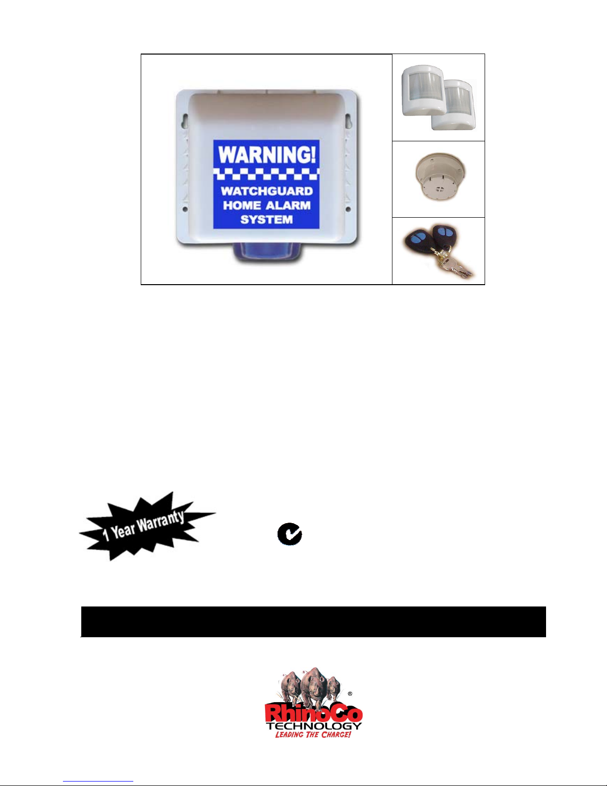
Your Watchguard Home Alarm System is a state-of-the-art wireless security system,
specifically designed for simple DIY installation (Do It Yourself). It is suitable for
use in homes or offices where the owner wishes an external & internal siren to trigger
if there is unauthorized entry into the premises.
Main Features include:
• Simple Installation
• Code Hopping Remote Control Technology (remotes can not be copied by
scanning or code grabbing).
• Remote Functions include arm, disarm, stay mode and panic.
• Ability to add or erase detectors from your system.
• 8 Wireless detector zones available
• Low Battery Warning & Supervision
• Detector 24 hour Tamper Alarm
• Protects your family and property
• Suitable for home and office
• Powerful external siren with flashing blue strobe
• Back up battery and main power adaptor
• High frequency internal siren to repel intruders
• Latest technology
• Wireless detectors available include Passive Infrared detectors, Reed Switches,
Shock detectors & Smoke detectors

5
1.1. The Passive Infrared Detector
The detector is a high quality infrared body movement detector, which is battery
operated and communicates with the Watchguard Home Alarm System via radio
frequency (RF) transmission. This detector is easy to install, provides excellent
detection sensitivity and has a long battery life (approximately 3 years). This detector
transmits four different codes to the main unit:
• Alarm – sent when a valid movement is detected
• Tamper – sent when the detector case is opened
• Supervision – sent every 2.5 hours to the main unit
• Low Battery – sent when the batteries need replacing
IMPORTANT NOTES
• NEVER
touch the pyro detector with your fingers
• During the warm up period, (first 3 minutes after installing the batteries) the
detector will not respond to the tamper switch or to movement in front of the
detector. You must wait 3 minutes before it will respond properly.
• This detector has Intelligent Power Saving (IPS). This means that in normal
operation the lights will not flash every time you move in front of the detector.
When the red light flashes on for 1 second, this means that the detector has
picked up and validated body movement (or an intruder) and an alarm code is
transmitted. The detector will now go into IPS mode for approximately 3
minutes. During this time the detector will not trigger and no lights will turn on
(see section 3.8.2. for more information).
• The wire, which runs around the edge of the detector, is the antenna. Do not
touch, remove or cut this wire
6
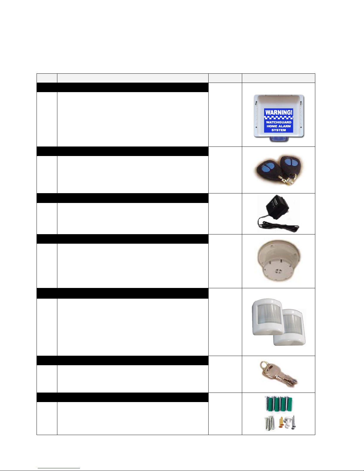
1.2. What You Get
Below is a list of parts included with system.
Item Description Quantity Image
1. Main control unit
1
The unit incorporates a powerful siren, flashing blue
strobe & backup battery to run the system in case of mains
power failure. There is also a tamper button. The system
has mains connection via a low voltage plug pack that is
supplied with the unit. For manual override of the system
there is a keyswitch on the main unit.
2. Remote controls
2
2 x High Security Code Hopping Remote Controls. These
allow you to easily arm & disarm the system from
anywhere in your home. In case of duress, you can trigger
the alarm at any time from the remote control.
3. Power Supply (plug pack)
1
The main unit requires a regular mains power supply.
The Watchguard is supplied with a 9V AC plug pack that
connects to the main unit.
4. Screamer
1
This high frequency siren generates an intolerable noise to
the human ear, and is designed to help repel intruders from
within your home. It mounts easily to the roof of one of
your rooms, and is simply cabled back to the main control
unit (10m of cable is provided).
5. Passive Infrared Detectors
2
Designed to detect the body movement of an intruder
inside your premises. These intelligent devices allow
simple installation, as no cable is required between the
main unit and the detectors. The long life lithium batteries
will last for up to 3 years, and the system will
automatically let you know when the batteries need
replacing.
6. High Security – Override keys
2
Used for manually overriding the system if both remote
controls are lost and also when the system is not being
used (in storage).
7. Mounting Material & Screws
4 large pan head screws, 4 green star plugs (for main unit),
4 medium counter sunk gyprock screws (for screamer), 2
wall plugs, 2 small counter sunk self tapping screws and
mounting brackets (for detectors).
7
2. Installation
2.1. Planning the Installation
Each separate component of the Watchguard Home Alarm System should be placed in
strategic locations. Below is a guide to where you should place the main unit, the
detectors and the screamer.
It is important that you take into account that the maximum range without any
obstructions between the main unit and each detector is no further than 50 metres.
Typically the range inside your house will be around 20-50 metres depending on the
construction of the house.
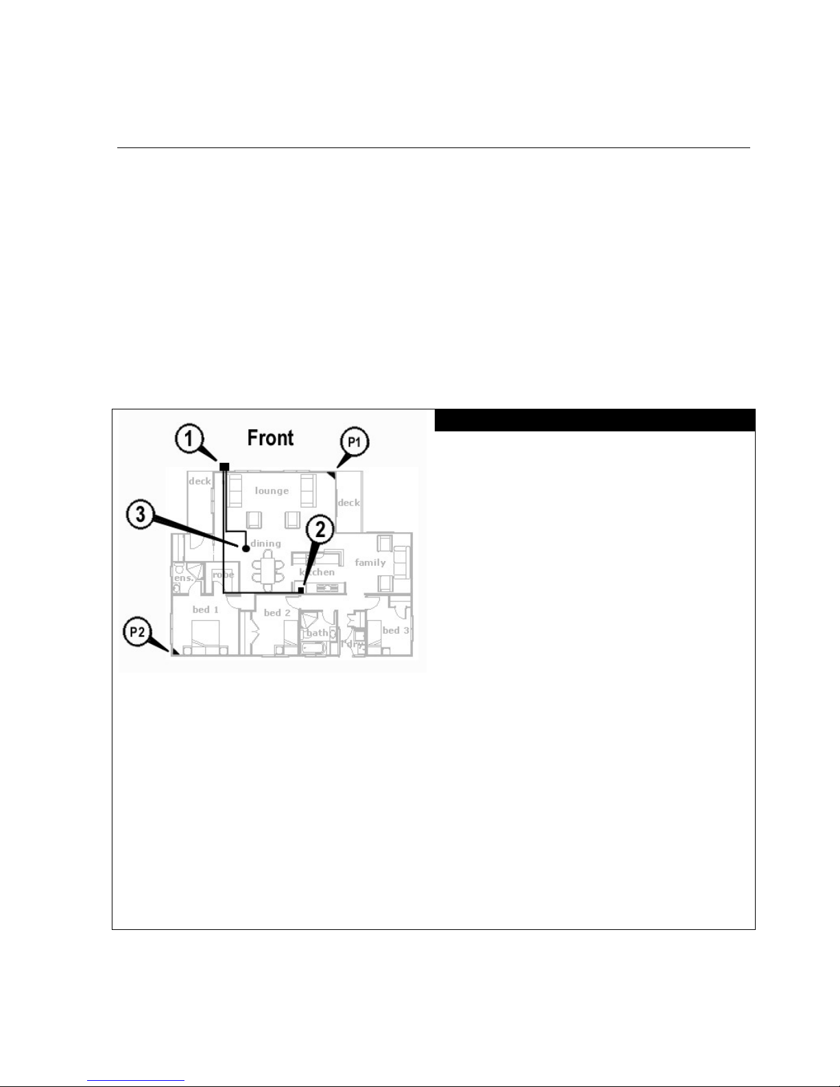
Planning and Wire Routing
1- The Watchguard main unit should
be located high on the front or front
side of the building under an eave
of covering. (See Section 2.2)
2- Route the white-white/black wire
(2 core-figure 8 cable) from the
main unit through the ceiling to
connect with the plug pack
connector. Another suitable
location for the power supply is on
an available power point at the rear
of the fridge in the kitchen. (See
Section 2.4)
3- Route the red-red/black wire (2
core-figure 8 cable) from the main
unit through the ceiling to connect
with the screamer connector. (See
Section 2.3)
P1- Location of passive infrared
detector zone 1. (Example only)
P2- Location of passive infrared
detector zone 2. (Example only)
Figure 1
8
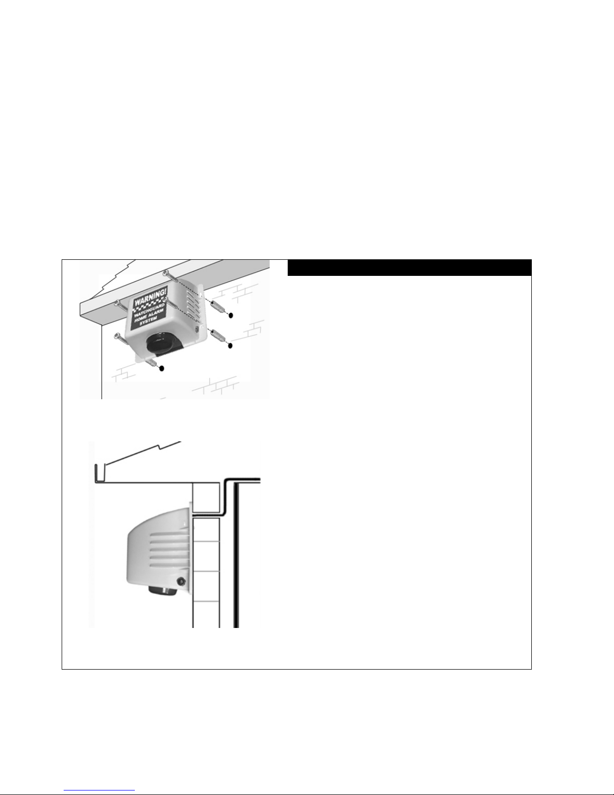
2.2. The Main Unit
Mount the Watchguard main unit at the front or front side of the building. The
mounting position should be under an eave or out of direct contact with rain or other
water sources. The position should allow line of sight viewing from both the street (for
visual deterrent) and from your main point of entry (for visual confirmation of
arming/disarming).
Use the wall plugs and screws provided if suitable for your particular building
construction.
Installing the main unit
1. Drill mounting holes (7mm diameter,
25mm minimum in depth) into the
chosen wall.
2. Use the green star plug. Press each
one into the 4 main mounting holes.
3. Make a hole and push the wires
through the wall and up into the
ceiling.
4. Screw the top 2 screws half way in.
5. Place the unit to support itself from
the top 2 screws through the key
shape holes at the top of the main
unit
6. Screw in and tighten the bottom two
mounting screws then tighten the top
two screws.
Figure 2
Figure 3
9
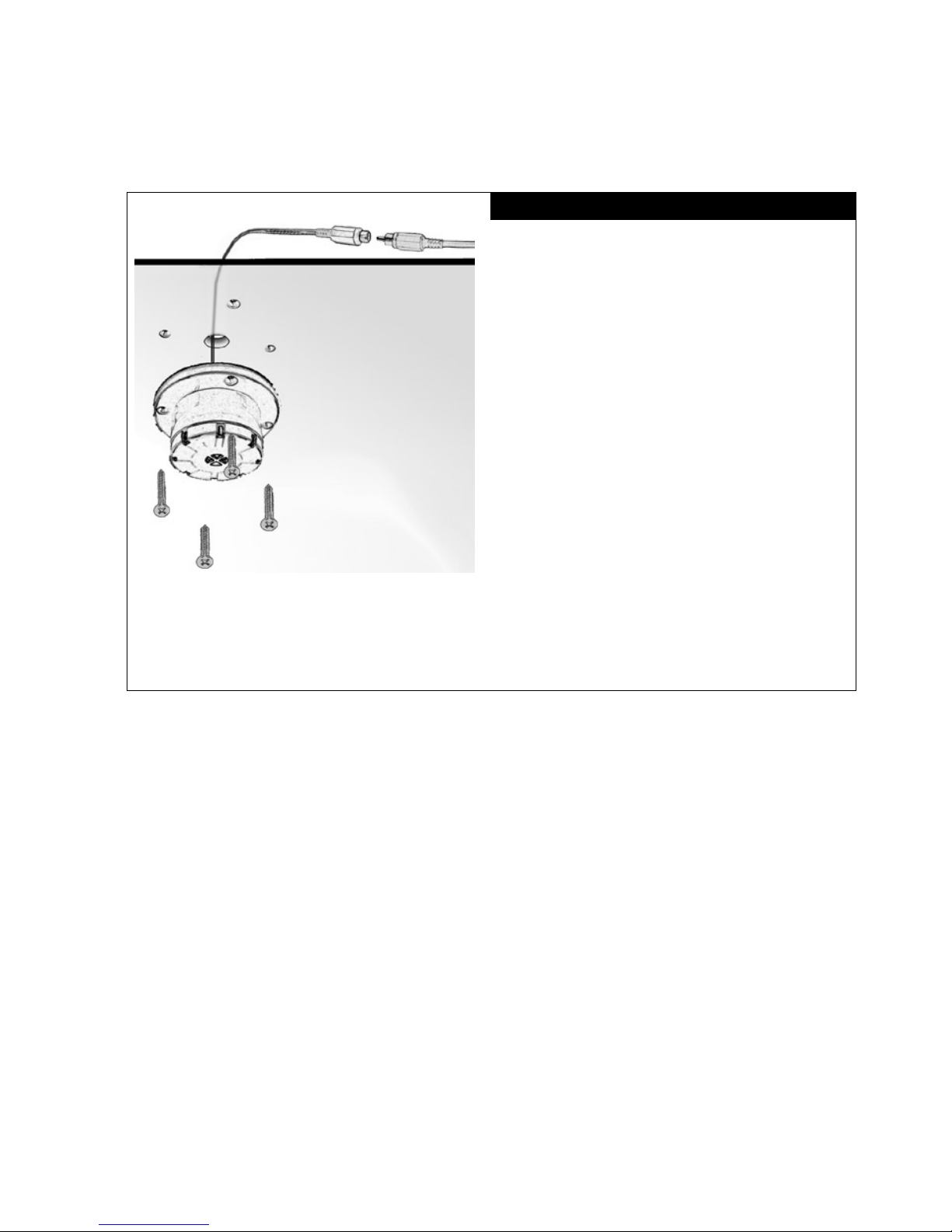
2.3. The Screamer
Inside Roof
Ceiling
Mounting the Screamer
1. Drill a hole (15mm diameter) into
the ceiling where you want to
mount the screamer. Pick a position
where there is no stud/framework
above the ceiling, preferably in a
corridor or hallway.
2. Feed the wire coming from the
screamer up through the 15mm hole
into the ceiling where it will join
the wire from the main unit.
3. Push the screamer on to the ceiling
aligning the hole with the wire
coming out of the screamer.
4. Place the self-tapping screws into
the mounting holes on the screamer
then screw them into the ceiling.
5. Connect the (red) female RCA plug
into the (red) male RCA plug.
Figure 4
10
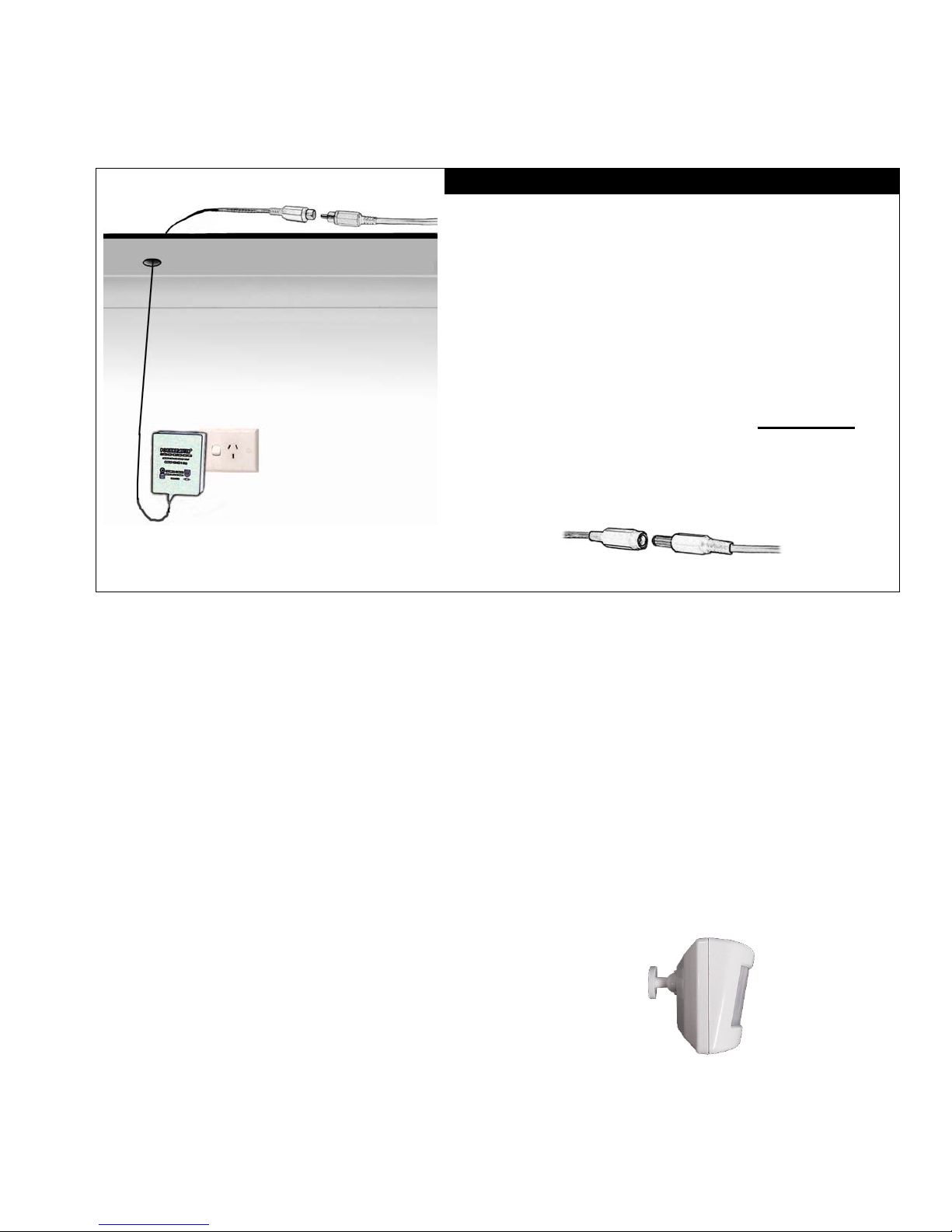
2.4. The Power Supply
Inside Roof
Wall
Power Supply Mounting
1. Drill a small hole (15mm diameter) into the
ceiling where the wire can go through to be
connected to the wire from the main unit.
2. Feed the wire through the hole in the ceiling
and up to where it will join the wire from the
main unit.
3. Connect the (black) female RCA connector
from the power supply into the (black) male
RCA plug from the main unit. Please note
that
the female RCA connector and the male RCA
plug set may be supplied as a (black) inline
DC socket and plug set as shown below.
Figure 5
For a truly secure and professional looking installation have a power point
installed in the ceiling by a qualified electrician so that the power supply (plug
pack) is hidden and unable to be accessed easily. Another location for the power
supply would be on an available power point at the rear of the fridge in the
kitchen.
2.5. The Detectors
Firstly, the mounting bracket must be fixed to the wall using the self-tapping screw
and other accessories supplied. Mounting must be at a minimum height of 1.2 metres
and maximum of 2.1 metres (lower is better).
Drill a 5mm diameter hole (at least 30mm deep) into the
gyprock for mounting the detector bracket/socket base.
Push the wall plug into the hole then screw in the
mounting bracket. It will clip into the base. The detector
can now be slid onto the swivel bracket. See diagram
below.
Approx mounting angle
at 2.1m
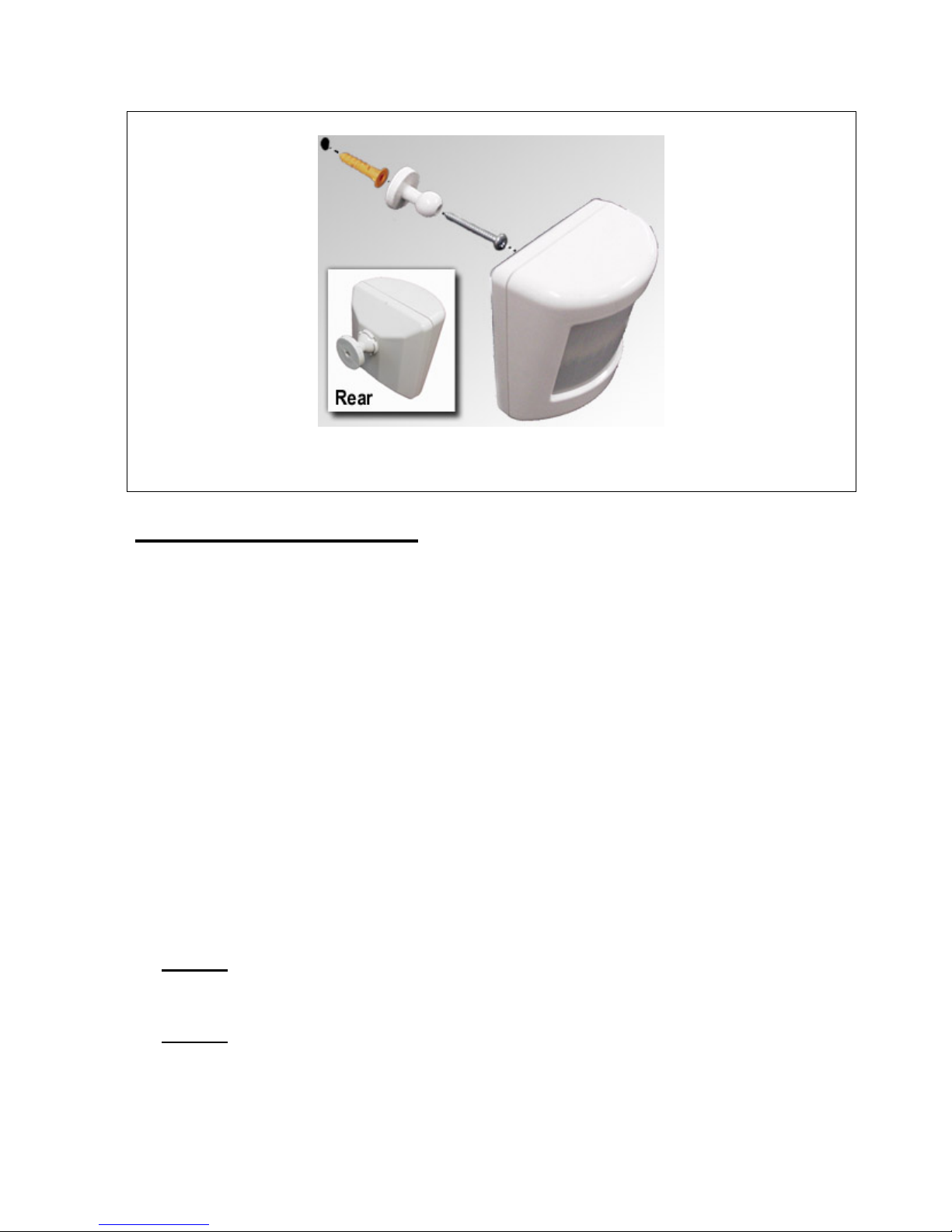
11
Figure 6
2.5.1. Tips for positioning
• This detector utilises the very latest in detection processing technology to reduce
the possibility of false alarms. However, correct mounting of the detector is critical
to ensure best detection or "catch" performance. You cannot just screw the detector
directly to a wall up high in a corner and expect best performance. Thoroughly
walk test each detector, and if detection is not acceptable in the location you have
chosen, adjust the angle of the detector slightly & re-test. You will find that a slight
up/down angle change may improve catch performance significantly.
• Mount the detector on your wall using the swivel mount provided at a minimum
height of 1.2 metres and maximum of 2.1 metres (lower is better). Make sure the
detector is a minimum of 5 metres away from your main unit so it doesn’t swamp
the receiver with a signal that is too strong to decode.
• Always mount your PIRW so that an intruder has to walk across its zones, i.e. walk
past the detector, not towards it.
• DON’T
mount detectors facing glass doors or windows. Always mount above
windows and doors to look inside.
• DON’T
mount detector facing hot areas or areas where the temperature may
change suddenly, e.g. open fire places, direct sunlight or air conditioning vents.
• Select a location where the detector can provide the best detecting range. Always
ensure that you do not cover an area with multiple detectors, so as to avoid

12
simultaneous transmission back to the receiver in your Watchguard Home Alarm
System. The receiver can only decode one coded signal at any given time.
• If the unit is mounted close to metal frames or doors, this may reduce the radio
transmitting range.
• The detector is not waterproof and is designed for indoor use only.
2.5.2. Powering the detector
When you first remove the detector from the box it is not
powered, although the batteries are in place. To turn the
detector on, pull the piece of plastic from beneath one of the
battery terminals (in the direction indicated in figure 8). As
soon as the plastic is removed the red and green lights will
flash for a few seconds.
If they do not flash, the plastic has not been removed
properly. You may need to clear any excess plastic from
under the battery terminal. If all plastic has been cleared and
the detector is still not responding then remove the batteries,
which the plastic was covering. Lift the bottom terminals and
push down the top terminals for tighter battery connections.
Slide the batteries back into their original position. If after
this you still don’t have any response from the detector then
the batteries may be flat.
IMPORTANT
2.5.3. Warm up period
You must wait approximately 3 minutes for the detector to
warm up after connecting the batteries. This time starts from
when the detector starts flashing both red and green lights
after removing the piece of plastic from under one of the
battery terminals. During this period the detector will not
respond and should be left untouched until the 3 minute
period is up. 3 minutes after power up, the green and red
lights will flash together 6 times to indicate the detector is
exiting test mode. The detector will now automatically enter
Intelligent Power Saving (IPS) mode (see section 3.8.2).
Figure 7
Unclip the front cover
as shown
Figure 8
 Loading...