

WATANABE WPMZ-5, WPMZ-6, MAX Induction SM-261R, MAX Induction SM-263R, MAX Induction SM-263RU Instruction Manual
...Page 1

WPMZ series
Modbus communication
instruction manual
Supported module type
WPMZ-5/6
Ver.1.30
Instruction manual number IM-0862-02
Page 2

WPMZ Series Modbus communication instruction manual
IM-0862-02
Number of pages:109
1
Table of contents
INTRODUCTION ....................................................................................................................................... 2
1. OVERVIEW ............................................................................................................................................ 3
2. MODULE COMMUNICATION SPECIFICATION ................................................................................ 4
2-1. SUPPORTED MODULES ............................................................................................................................ 4
2-2. MODULE COMMUNICATION SPECIFICATION ............................................................................................. 4
2-3. MODULE WIRING (RS-485 COMMUNICATION OPTION) ............................................................................. 5
2-3-1. Wiring method ................................................................................................................................ 5
2-3-2. Connection terminal ....................................................................................................................... 5
2-3-3. Configuration diagram example .................................................................................................... 6
2-4. MODULE WIRING (RS-232C COMMUNICATION OPTION) .......................................................................... 8
2-4-1. Connection terminal ....................................................................................................................... 8
2-4-2. Configuration diagram example .................................................................................................... 8
3. MODBUS COMMUNICATION SPECIFICATION .................................................................................................... 9
3-1. COMMUNICATION PROCEDURE ................................................................................................................ 9
3-2. TRANSMISSION SWITCHING TIME ............................................................................................................ 9
3-3. MESSAGE ............................................................................................................................................... 10
3-3-1. Composition of messages ............................................................................................................. 10
3-3-2. Message Contents ......................................................................................................................... 10
3-3-3. Types of data ................................................................................................................................. 10
3-3-4. Slave ID ......................................................................................................................................... 10
3-3-5. Function code ................................................................................................................................. 11
3-3-6. Format Details ............................................................................................................................... 11
3-4. ERROR DETECTION ................................................................................................................................ 17
3-4-1. CRC-16 .......................................................................................................................................... 17
3-4-2. Calculation of CRC-16 .................................................................................................................. 17
3-5. ERROR MESSAGE ................................................................................................................................... 20
4. COMMUNICATION EXAMPLE .......................................................................................................... 21
4-1. WPMZ-5/6 ............................................................................................................................................ 21
4-1-1. Acquire measurement data .......................................................................................................... 21
4-1-2. Change control parameters .......................................................................................................... 22
4-1-3. Change setting parameters .......................................................................................................... 23
5. ADDRESS MAP .................................................................................................................................... 26
5-1. WPMZ-5/6 ............................................................................................................................................ 26
5-1-1. Setting and control parameters ................................................................................................... 26
5-1-2. Measurement data...................................................................................................................... 105
6. TROUBLESHOOTING........................................................................................................................ 108
6-1. ABOUT COMMUNICATION ..................................................................................................................... 108
6-1-1. Communication abnormal .......................................................................................................... 108
6-1-2. The acquired data is abnormal .................................................................................................. 108
Modbus is a registered trademark of Modicon Inc. (AEG Schneider Automation International S.A.S.).
Page 3
WPMZ Series Modbus communication instruction manual
IM-0862-02
Number of pages:109
2
Introduction
This instruction manual explains notes, information and setting method when using Modbus communication of
WPMZ series.
Please observe the following in order to use the product correctly and safely.
○ Please read this instruction manual thoroughly before use and use it properly.
○ Before constructing the system, carefully read the Modbus compatible products and other equipment 's
instruction manuals to be used, and use them correctly.
○ After reading, carefully keep it and read it when you need it.
Usage restrictions
● Please note that the contents of this manual may be changed without notice.
We will not be held responsible in any case for special damages, indirect
damages, losses caused by this manual.
In this operation manual, hexadecimal data is indicated by appending "H" after the numerical value. Nothing is
appended to decimal data.
Example) Hexadecimal number: 123H, decimal number: 123
Page 4

WPMZ Series Modbus communication instruction manual
IM-0862-02
Number of pages:109
3
1. Overview
We will explain the specification of Modbus communication of WPMZ series.
This manual is intended for engineers who connect from Modbus Master to Modbus compatible products and
create processing to collect settings and data.
As a Modbus master, it is assumed to be a PC or Programmable Logic Controller (PLC). Please
prepare equipment to be used for Modbus master in advance.
First, refer to "2. Module communication specification" and set the module (WPMZ - 5/6) connected to
the Modbus master so that it conforms to the communication specifications.
Then refer to "5. Address Map" of the corresponding module according to "3. Modbus communication
specification" and set and read the necessary items.
Page 5
WPMZ Series Modbus communication instruction manual
IM-0862-02
Number of pages:109
4
2. Module communication specification
2-1. Supported Modules
The corresponding modules assumed in this manual are as follows.
WPMZ-5
WPMZ-6
2-2. Module communication specification
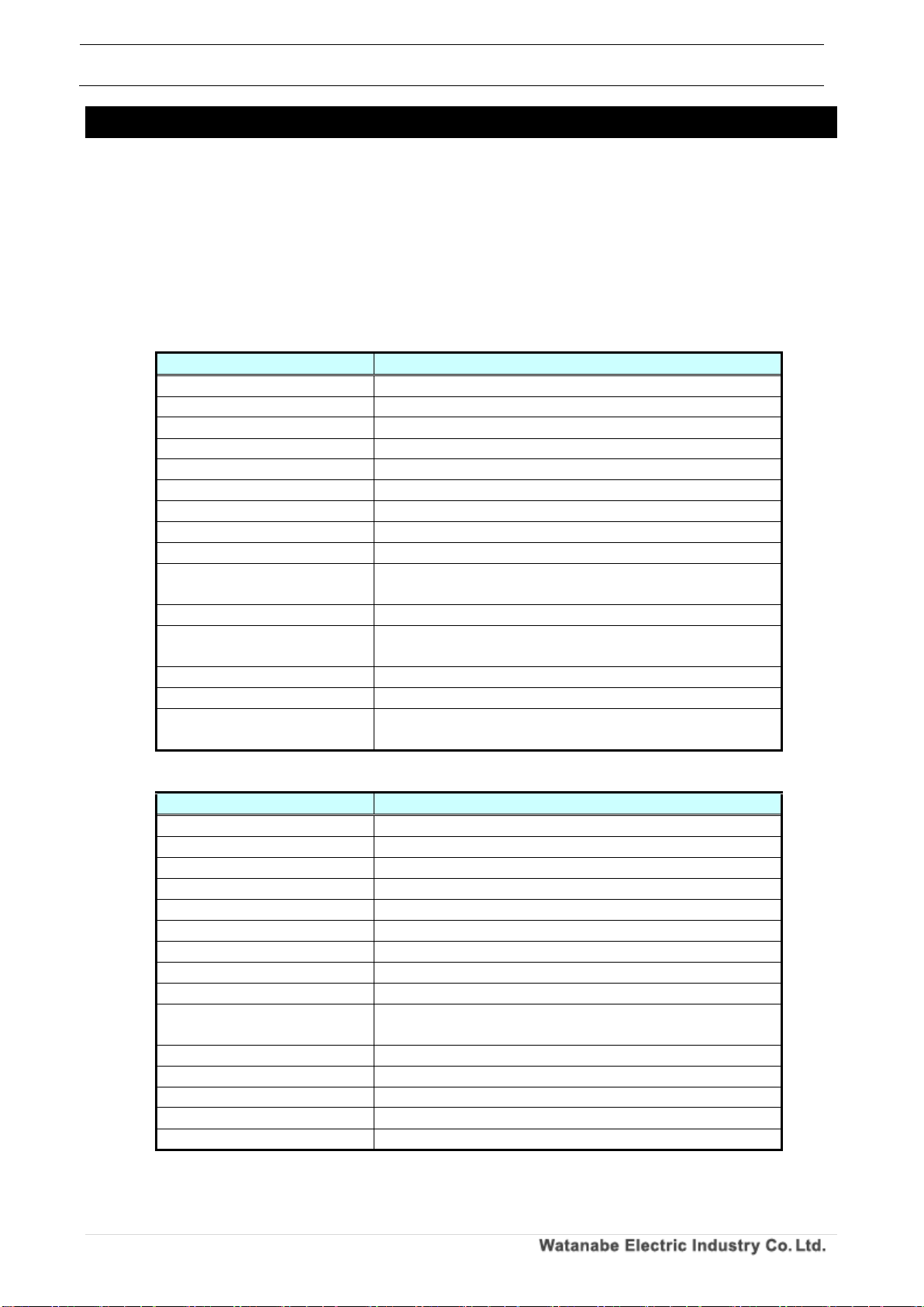
The communication specifications when connecting to each module are as shown in the table below.
Table 2.1 Communication specification of module (RS-485 communication option)
WPMZ-5/6
Standard
RS-485 compliant
Protocol
Modbus(RTU)
Synchronous mode
Asynchronous type
Communication method
2-wire half-duplex
Error detection method
CRC-16
communication speed
9600bps、19200bps、38400bps
Data length
8 (fixed)
Start bit
1(fixed)
Parity bit
Selection from eve, odd, none
Stop bit
1、2
(Stop bit 2 can be set only when there is no parity)
Signal name used
Non-inverted (+), inverted (-)
Terminating resistance
Approximately 120 Ω (Connected by short-circuiting TERM
terminals)
Number of connected units
31 (number of slave devices)
Configurable address
1~31 (0 can not be used)
Transmission distance (total)
1.2km
※For CE mark conformance, less than 30 m
Table 2.2 Module communication specification (RS-232C communication option)
WPMZ-5/6
Standard
RS-232C compliant
Protocol
Modbus(RTU)
Synchronous mode
Asynchronous type
Communication method
Full duplex
Error detection method
CRC-16
communication speed
9600bps、19200bps、38400bps
Data length
8 (fixed)
Start bit
1(fixed)
Parity bit
Selection from eve, odd, none
Stop bit
1、2
(Stop bit 2 can be set only when there is no parity)
Signal name used
TXD、RXD、SG
Terminating resistance
-
Number of connected units
1 (number of slave devices)
Configurable address
1 only (0 can not be used)
Transmission distance (total)
15m
Page 6
WPMZ Series Modbus communication instruction manual
IM-0862-02
Number of pages:109
5
2-3. Module wiring (RS-485 communication option)
2-3-1. Wiring method
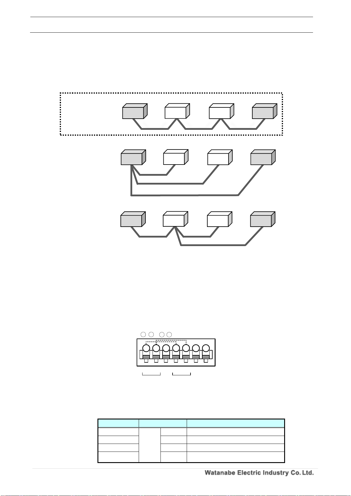
The Modbus communication wiring is wired in a daisy chain (daisy chaining).
If there are multiple branches from the star wiring or module, it may not be able to communicate
properly.
2-3-2. Connection terminal
This section describes the Modbus (RS485) connection terminals of the module.
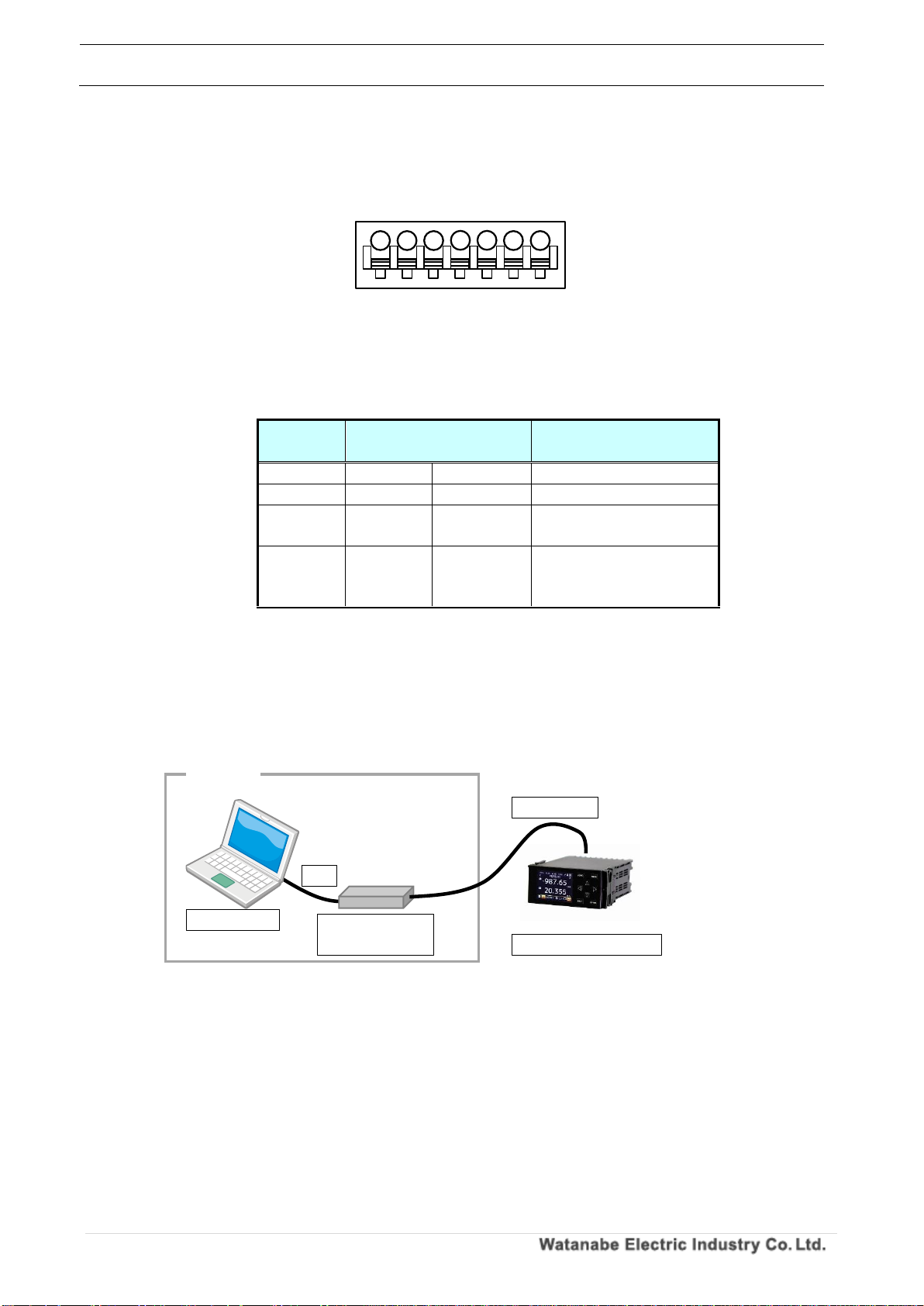
1. WPMZ-5/6
Modbus (RS485) connection terminal of WPMZ-5/6 is as shown below.
28 and 31, 29 and 32 are conducting inside the equipment respectively.
(Since the connector inside does not have continuity, communication lines and remove the connector
will be disconnected.)
Table 2.3 Connector contents
Symbol
Contents
28,31
RS485
+
Non-inverting signal
29,32
-
Inverting signal
30
SG
Signal ground
33,34
Terminal resistance (120Ω)terminals
* Short 33 and 34 to be enable the resistance.
Figure 2.1 Wiring of Modbus communication
terminal
terminal
terminal
terminal
terminal
terminal
Correct wiring
(Daisy chain)
Incorrect wiring
(Star wiring)
Incorrect wiring
(There is a branch
on the way)
Figure 2.2 Modbus communication wiring
+
RS-485
TERM
TERM
SG
-
+
RS-485
-
34
28 29
30
31
32
33
* 、 & 、 :connected internally
28 31
29 32
Suitable wire:AWG24 to 16
Master
Master
Master
Page 7
WPMZ Series Modbus communication instruction manual
IM-0862-02
Number of pages:109
6
2-3-3. Configuration diagram example
The configuration example of WPMZ - 5/6 is shown below.
1. About communication cable
Please use a shielded cable that meets the following specifications.
Table 2.4 Communication cable specification
Product name
Size
Total cable extension
WPMZ-5/6
AWG24~16
1.2km or less
2. About connection of terminating resistor
Up to 31 slaves (modules) can be connected.
At that time, please set the terminating resistor for the module which becomes the terminal equipment
of the line.
In the case of WPMZ-5/6, connect the TERM terminals together.
If this product is not a terminal equipment of the line, please do not set the termination resistor.
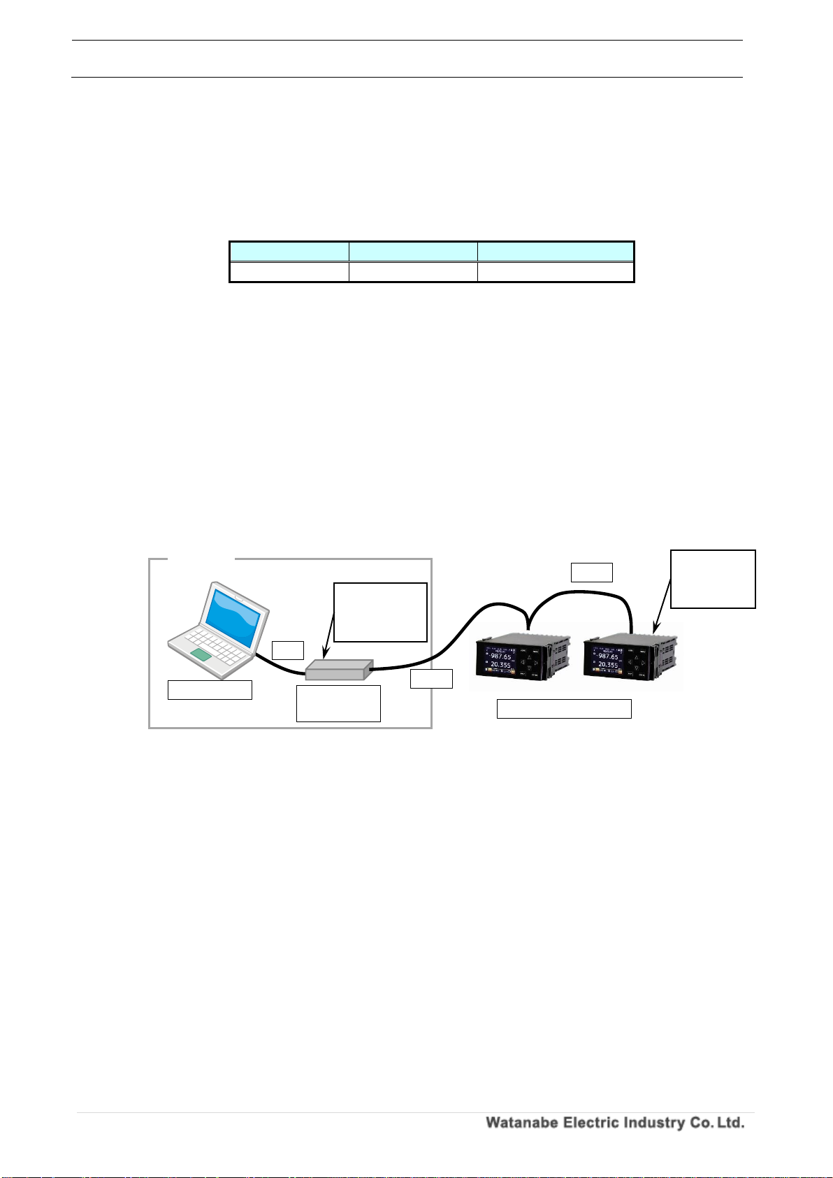
When connecting via Modbus using the USB - RS 485 converter, even if the master is a personal
computer, set the terminating resistor in the USB - RS 485 converter. (See the figure below)
Note: Do not configure multiple masters to connect to the same slave (module).
Communication may not be performed correctly and data may not be taken.
Figure 2.3 Terminating resistance when USB-RS 485 converter is used
Master
Set the
terminating
resistance
Set the
terminating
resistance
USB-RS485
converter
Computer
Slave (module)
USB
RS485
RS485
Page 8
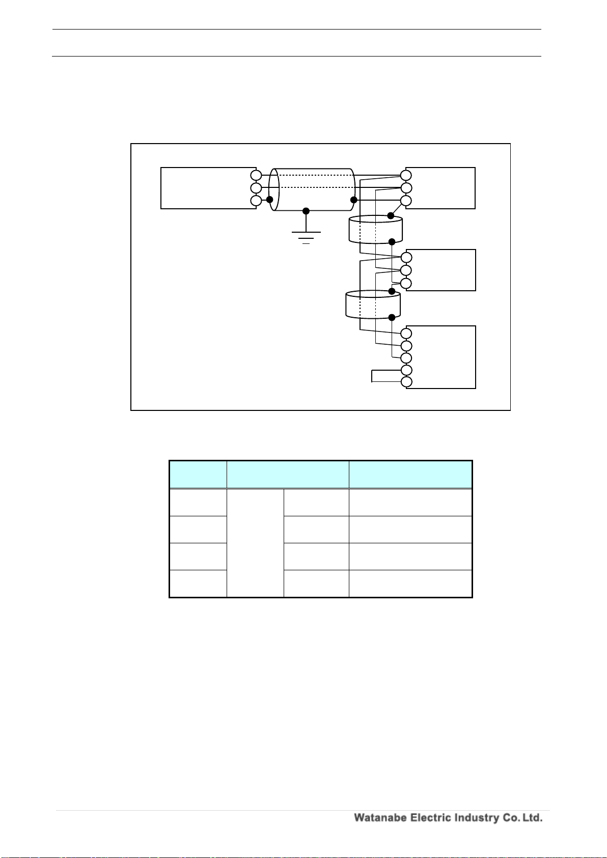
WPMZ Series Modbus communication instruction manual
IM-0862-02
Number of pages:109
7
3. Connection diagram
The Modbus connection of WPMZ - 5/6 is shown below.
Please set the terminating resistance to the master and slave at the final end (WPMZ in the figure
below).
Table 2.5 Modbus connection terminal (WPMZ - 5/6)
Terminal
number
symbol
Contents
28,31
RS485
+
Communication plus
terminal
29,32
-
Communication minus
terminal
30
SG
Communication SG
terminal
33,34
TERM (※)
Terminal resistor terminal
(120 Ω)
※ When connecting the TERM terminals to each other, the terminating resistance becomes
effective.
Figure 2.4 Modbus connection of WPMZ-5/6
With
terminating
resistance
Shield cable
Shield cable
※ When WPMZ - 5/6 is
terminated, connect the
TERM terminals together.
Twisted pair wire
WPMZ-5/6:AWG24~16
Slave
Slave
WPMZ
Master
SG
SG
+
+
+
+
SG
S
T
T
Shield cable
Page 9
WPMZ Series Modbus communication instruction manual
IM-0862-02
Number of pages:109
8
2-4. Module wiring (RS-232C communication option)
2-4-1. Connection terminal
The figure below shows the RS - 232C connection terminal of WPMZ - 5/6.
Table 2.6 Connector contents
Terminal
number
symbol
Contents
28 RXD
Receive terminal
29 TXD
Transmission terminal
30 SG
Common terminal of
communication function
31~34
NC
Not connected ※ Please
do not use as relay
terminal.
2-4-2. Configuration diagram example
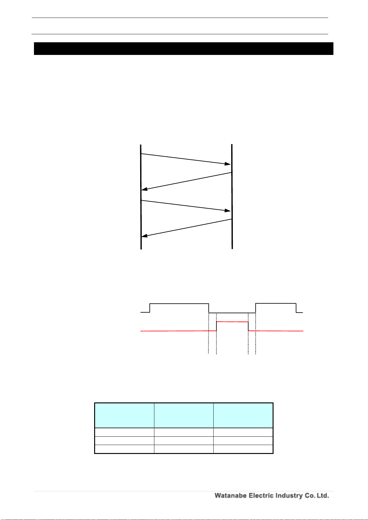
The configuration example of WPMZ - 5/6 is shown below.
Master and slave (module) are connected 1: 1.
Specify "1" for the slave address of the Modbus protocol.
Figure 2.5 Wiring of RS-232C communication
Figure 2.6 When USB-RS232C converter is used
マスター
USB RS-232C
converter
computer
Slave (module)
USB
RS-232C
RXD
TXD
SG
NC
NC
NC
NC
34
28 29 30
31
32
33
Suitable wire:AWG24 to 16
Page 10
WPMZ Series Modbus communication instruction manual
IM-0862-02
Number of pages:109
9
3. Modbus communication specification
Modbus is a single master / multislave system.
A message is sent from one Modbus master to the slave (module). The message is sent to the specified slave
(module).
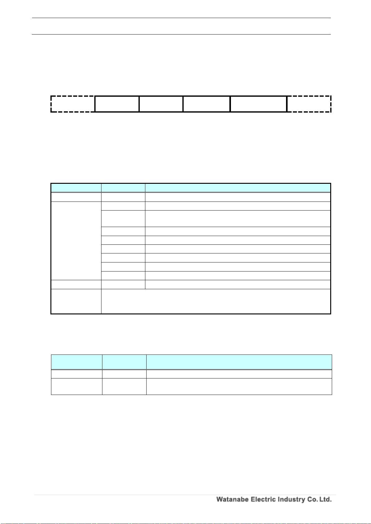
3-1. Communication procedure
When the master sends a command message, the slave (module) sends a response message to the
contents of the message.
The operations of the master side message and the slave side message are as follows.
3-2. Transmission Switching Time
In communication between master and slave, idle time for 3.5 characters is required for transmission /
reception switching.
Please refer to the table below for the idle time for 3.5 characters.
In the WPMZ-5/6 series, the communication speed and parity setting can be changed.
Table 3.1 3.5 character idle time (reference value)
communication
speed
With parity
(Even number, odd
number)
No parity
9600bps
4.01ms
3.65ms
19200bps
2.01ms
1.82ms
38400bps
1.00ms
0.91ms
Master
Slave
(module)
Command
message
Response
message
Command
message
Response
message
Figure 3.1 Communication procedure
Master side message
transmission
Slave side message
response
Idle time
Idle time
Page 11
WPMZ Series Modbus communication instruction manual
IM-0862-02
Number of pages:109
10
3-3. Message
3-3-1. Composition of messages
After securing an idle interval of 3.5 character transmission time or longer, it transmits a communication
message and ends after an idle time of 3.5 character transmission time or more.
Id l e 3. 5
ch a r a ct e r s
Sl a ve I D
Fu n c t i o n
co d e
Th e d a t a
Er r or c h e c k
CRC-16
Id l e 3. 5
ch a r a ct e r s
1b y te
1b y te
2~ 250b y t e
(v a r i ab l e
le n g t h )
2b y te
3-3-2. Message Contents
In the structure of the above message, descriptions of data and contents that can be set are shown in
the table below.
Table 3.2 Message contents
item
Setting data
Contents
Slave ID
01~1FH
Slave ID (maximum number of connected units is 31)
Function code
03H
Read held register
04H
Read input register
(Read only address)
06H
Hold register 1 word write
08H
Diagnosis
0BH
Read event counter
0CH
Read event log
10H
Holding register Continuous write
11H
Read slave information
The data
-
Data (variable length by command)
Error check
(CRC-16)
Calculate CRC-16 from the slave ID to the last byte of the data and add CRC-16 (2
bytes) of the operation result to the data in the order of the lower byte and the
upper byte.
3-3-3. Types of data
Modbus data has two input register and holding register.
Table 3.3 Types of data
Types of data
Reading and
writing
Details
Input register
Read only
It is used to acquire the information in the slave.
Holding register
Reading and
writing
It is used to acquire and set slave control information / setting
information.
3-3-4. Slave ID
It returns a response message only when the received message matches the ID value set in the
module.
If they do not match, no response message is returned.
Page 12
WPMZ Series Modbus communication instruction manual
IM-0862-02
Number of pages:109
11
3-3-5. Function code
The function code is a code that specifies the operation to be made slave, and it is included in the
message sent from the master to the slave.
The function codes described in this manual are shown in the table below.
Table 3.4 Function code list
Function
code
Feature Description
03H
Read held register
04H
Read input register
(Read only address)
06H
Hold register 1 word write
08H
Diagnosis
10H
Holding register Continuous write
3-3-6. Format Details
Explain the detailed format for each function code.
Caution
Please be aware that the error checking CRC in each format is added in order of lower byte and higher byte.
1. Function code 03H (Read held register)
Read the parameter value of the specified address.
Tran s miss i on a nd rece p tion for m at
◎Transmission data (master → slave (module))
Table 3.5 Function code 03H Transmission format
na m e
Tr a n s mi tt e d da ta
Sl a ve I D
01 ~ F F H
Fu n c t io n c o d e
03H
Ad d re s s
Up p e r
0000 ~ 27 0F H
Lo w er
Nu m be r o f w o r d s t o be
re a d( D a t a le n g th ÷ 2 )
Up p e r
0001 ~ 00 7D H
Lo w er
Er r or c h e c k
(CRC- 16)
Up p e r
0000 ~ FF F F H
Lo w er
※Specify the number of read words in units of data length for each address.
◎Received data (slave (module) → master)
Table 3.6 Function code 03H Reception format
na m e
Re c e i ve d d a t a
Sl a ve I D
01 ~ F F H
Fu n c t io n c o d e
03H
Nu m be r o f by te s r ea d
2 × n u mb e r of r e a d w or d s
Fi r s t w o r d d a t a
Up p e r
0000 ~ FF F F H
Lo w er
Ne x t w o r d da ta
Up p e r
0000 ~ FF F F H
Lo w er
~
~
~
Th e l as t w or d d a t a
Up p e r
0000 ~ FF F F H
Lo w er
Er r or c h e c k
(CRC- 16)
Lo w er
0000 ~ FF F F H
Up p e r
Page 13
WPMZ Series Modbus communication instruction manual
IM-0862-02
Number of pages:109
12
2. Function code 04H (Read input register [Read only address])
Read the measurement value of the specified read-only address.
Tran s miss i on a nd r ece p tion form a t
◎Transmission data (master → slave (module))
Table 3.7 Function code 04H Transmission format
na m e
Tr a n s mi tt e d da ta
Sl a ve I D
01 ~ F F H
Fu n c t io n c o d e
04H
Ad d re s s
Up p e r
0000 ~ 27 0F H
Lo w er
Nu m be r o f w o r d s t o be
re a d( D a t a le n g th ÷ 2 )
Up p e r
0001 ~ 00 7D H
Lo w er
Er r or c h e c k
(CRC- 16)
Lo w er
0000 ~ FF F F H
Up p e r
※Specify the number of read words in units of data length for each address.
◎Received data (slave (module) → master)
Table 3.8 Function code 04H Reception format
na m e
Re c e i ve d d a t a
Sl a ve I D
01 ~ F F H
Fu n c t io n c o d e
04H
Nu m be r o f by te s r ea d
2 × n u mb e r of r e a d w or d s
Fi r s t w o r d d a t a
Up p e r
0000 ~ FF F F H
Lo w er
Ne x t w o r d da ta
Up p e r
0000 ~ FF F F H
Lo w er
~
~
~
Th e l as t w or d d a t a
Up p e r
0000 ~ FF F F H
Lo w er
Er r or c h e c k
(CRC- 16)
Lo w er
0000 ~ FF F F H
Up p e r
Page 14

WPMZ Series Modbus communication instruction manual
IM-0862-02
Number of pages:109
13
3. Function code 06H (Write 1 word of holding register)
Writes 1 word (2 bytes) of data to the specified writable address.
Tran s miss i on a nd r ece p tion form a t
◎Transmission data (master → slave (module))
Table 3.9 Function code 06H Transmission format
na m e
Tr a n s mi tt e d da ta
Sl a ve I D
01 ~ F F H
Fu n c t io n c o d e
06H
Ad d re s s
Up p e r
0000 ~ 27 0F H
Lo w er
Wr i te w o r d d a t a
Up p e r
0000 ~ FF F F H
Lo w er
Er r or c h e c k
(CRC- 16)
Lo w er
0000 ~ FF F F H
Up p e r
◎Received data (slave (module) → master)
Table 3.10 Function code 06H Reception format
na m e
Re c e i ve d d a t a
Sl a ve I D
01 ~ F F H
Fu n c t io n c o d e
06H
Ad d re s s
Up p e r
0000 ~ 27 0F H
Lo w er
Wr i te w o r d d a t a
Up p e r
0000 ~ FF F F H
Lo w er
Er r or c h e c k
(CRC- 16)
Lo w er
0000 ~ FF F F H
Up p e r
Page 15

WPMZ Series Modbus communication instruction manual
IM-0862-02
Number of pages:109
14
Fun c tion code 08H ( dia g n osi s )
It is a communication that diagnoses the communication between the master and the slave and
diagnoses the module.
Tran s miss i on a nd r e cep t i on f orma t
◎Transmission data (master → slave (module))
Table 3.11 Function code 08H Transmission format
na m e
Tr a n s mi tt e d da ta
Sl a ve I D
01 ~ F F H
Fu n c t io n c o d e
08 H
Di a g n os t i c s u b c o d e
Up p e r
0000 ~ 0012H
Lo w er
Da t a f i e l d
Up p e r
0000 ~ FF F F H
Lo w er
Er r or c h e c k
(CRC- 16)
Lo w er
0000 ~ FF F F H
Up p e r
◎Received data (slave (module) → master)
Table 3.12 Function code 08H Reception format
na m e
Re c e i ve d d a t a
Sl a ve I D
01 ~ F F H
Fu n c t io n c o d e
08H
Di a g n os t i c s u b c o d e
Up p e r
0000 ~ 0015H
Lo w er
Da t a f i e l d
Up p e r
0000 ~ FF F F H
Lo w er
Er r or c h e c k
(CRC- 16)
Lo w er
0000 ~ FF F F H
Up p e r
Dia g n osti c su b cod e an d dia g nost i c c o nten t
The corresponding diagnostic subcode is shown in the table below.
Table 3.13 Corresponding diagnostic subcode
Diagnostic
subcode
Diagnostic name
Diagnosis contents
00H
Return Query Data
It returns the data of the transmitted data field as it
is.
01H
Restart Communications Option
Restart communication.
02H
Return Diagnostics Register
Returns diagnostic register (fixed as 0 because it is
not used).
04H
Force Listen Only Mode
Set the slave to receive only mode.
0AH
Clear Counters and Diagnostic Register
Clear all counters and diagnostic registers.
0BH
Return Bus Message Count
Returns the total of messages detected by the slave.
0CH
Return Bus Communication Error Count
Returns the total of CRC errors detected by the
slave.
0DH
Return Bus Exception Error Count
Returns the sum of exception responses of Modbus
returned by the specified slave.
0EH
Return Server Message Count
Returns the total of messages received by the
specified slave.
0FH
Return Server No Response Count
Returns the total of messages for which the
specified slave did not respond.
10H
Return Server NAK Count
Returns the total of messages that the specified
slave returned NAK.
Page 16
WPMZ Series Modbus communication instruction manual
IM-0862-02
Number of pages:109
15
11H
Return Server Busy Count
Returns the number of times slave, busy, exception
response returned by the specified slave.
12H
Return Bus Character Overrun Count
Returns the number of times a character overrun
error occurred on the specified slave.
Dia g n osti c fu n cti o n co m muni cati o n exam p le
Communication is performed with the diagnosis subcode 00H (Return Query Data) for the module
with slave ID 01H.
An example of specifying 55AAH for write word data is shown below.
・Transmission data (master → slave (module))
Table 3.14 Function code 08H Transmission data
na m e
Tr a n s mi tt e d
da t a
Sl a ve I D
01H
Fu n c t io n c o d e
08H
Di a g n os t i c s u b c o d e
Up p e r
00H
Lo w er
00H
Da t a f i e l d
Up p e r
55H
Lo w er
AA H
Er r or c h e c k
(CRC- 16)
Lo w er
5F H
Up p e r
24H
・Received data (slave (module) → master)
Table 3.15 Function code 08H Receive data
na m e
Re c e i ve d
da t a
Sl a ve I D
01H
Fu n c t io n c o d e
08H
Di a g n os t i c s u b c o d e
Up p e r
00H
Lo w er
00H
Da t a f i e l d
Up p e r
55H
Lo w er
AA H
Er r or c h e c k
(CRC- 16)
Lo w er
5F H
Up p e r
24H
Page 17
WPMZ Series Modbus communication instruction manual
IM-0862-02
Number of pages:109
16
4. Function code 10H (hold register consecutive write)
Writes contiguous data to the specified writable address.
Tran s miss i on a nd r e cep t i on f orma t
◎Transmission data (master → slave (module))
Table 3.16 Function code 10H Transmission format
na m e
Tr a n s mi tt e d da ta
Sl a ve I D
01 ~ F F H
Fu n c t io n c o d e
10H
St a rt a d d r es s
Up p e r
0000 ~ 27 0F H
Lo w er
Th e n um b e r o f d a t a
Up p e r
0002 ~ 0 1 FE H
Lo w er
Nu m be r o f by te s
01 ~ F F H
Fi r s t w r i t e w o r d da ta
Up p e r
0000 ~ FF F F H
Lo w er
Ne x t w r i t e w or d d at a
Up p e r
0000 ~ FF F F H
Lo w er
~
~
~
La s t wr i t e w o r d d a t a
Up p e r
0000 ~ FF F F H
Lo w er
Er r or c h e c k
(CRC- 16)
Lo w er
0000 ~ FF F F H
Up p e r
◎Received data (slave (module) → master)
Table 3.17 Function code 10H Reception format
na m e
Re c e i ve d d a t a
Sl a ve I D
01 ~ F F H
Fu n c t io n c o d e
10H
St a rt a d d r es s
Up p e r
0000 ~ 27 0F H
Lo w er
デー タ 数
Up p e r
0002 ~ 0 1 FE H
Lo w er
Er r or c h e c k
(CRC- 16)
Lo w er
0000 ~ FF F F H
Up p e r
Page 18

WPMZ Series Modbus communication instruction manual
IM-0862-02
Number of pages:109
17
3-4. Error detection
3-4-1. CRC-16
CRC - 16 is 2 - byte error check data. The calculation range is from the slave ID at the head of the
message to the end of the data part.
The slave (module) calculates the CRC of the received message, and if it does not match the received
CRC code, it becomes no response and the function is not executed.
3-4-2. Calculation of CRC-16
To calculate the CRC, divide the transmission data by the generator polynomial (X16 + X15 + X2 + X0)
and set the remainder in the order of the lower byte and upper byte in the error check.
The following is an example of generating with command data from the master device.
① Area initialization: Substitute FFFFH for 【CRC - 16】.
② Assign the calculated value of 【CRC - 16】 XOR 【first data (here, slave ID data)】 to 【CRC -
16】.
③ Assign [CRC - 16] to the right by one bit shifted to [CRC - 16].
④ If CF (carry flag) = 1, substitute the calculated value of [CRC - 16] XOR A 001 H into [CRC -
16] according to 3) above. (CF shifts to the right when shifting right one bit when the least
significant bit is 1).
⑤ Repeat ③ and ④ above 8 times. After the end of 8 times, go to ⑥.
⑥ If the last data has been completed, add [CRC - 16] as a calculation result to the message and
exit. If not finished, go to ⑦.
⑦ Assign the calculated value of 【CRC - 16】 XOR 【next data】 to 【CRC - 16】 and go to ③.
Page 19
WPMZ Series Modbus communication instruction manual
IM-0862-02
Number of pages:109
18
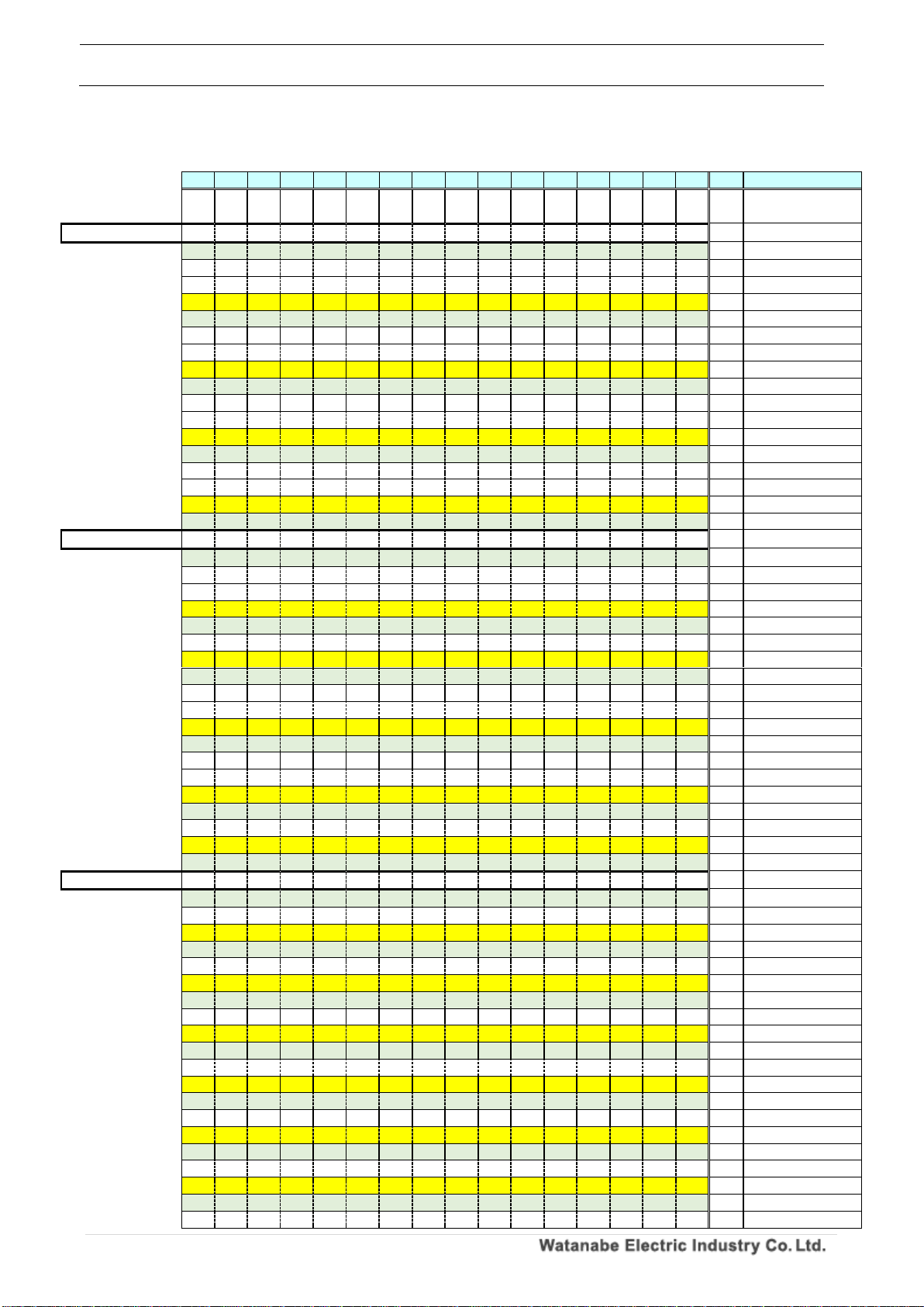
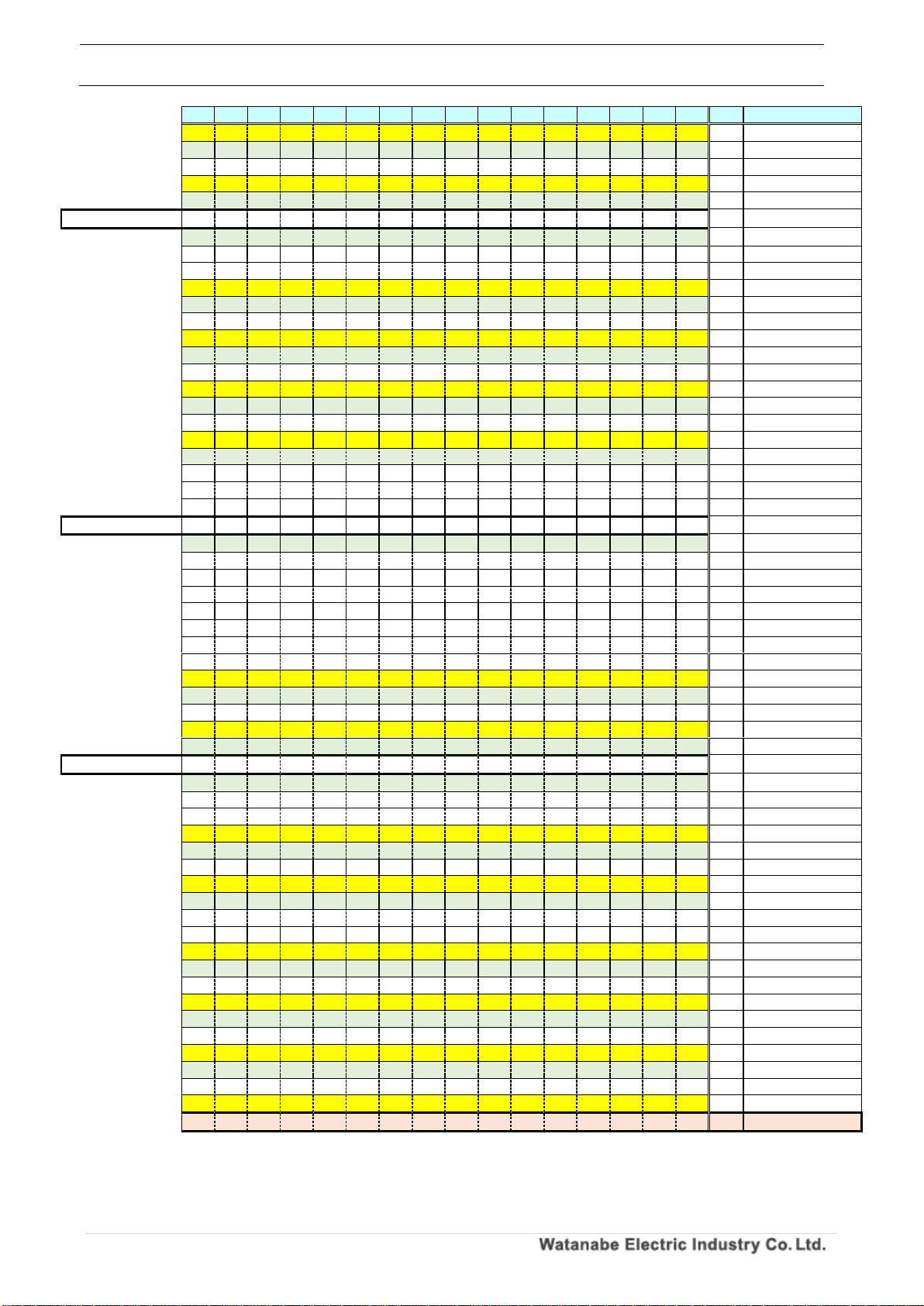
Calc ulat i on e x ampl e : P e rfor m CRC cal c ulat i on o f 01 0 4000 0 0002 .
Table 3.18 Calculated data example: 010400000002 (6 bytes data)
16
15
14
13
12
11
10 9 8 7 6 5 4 3 2 1 CF
説明
1 1 1 1 1 1 1 1 1 1 1 1 1 1 1
1
-
FFFFH
(initialization)
01 (1st byte)
0 0 0 0 0 0 0 0 0 0 0 0 0 0 0
1 -
1 1 1 1 1 1 1 1 1 1 1 1 1 1 1
0 - XOR top two rows
right shift 1st
0 1 1 1 1 1 1 1 1 1 1 1 1 1 1
1 0
right shift 2nd
0 0 1 1 1 1 1 1 1 1 1 1 1 1 1
1 1 CF became 1
1 0 1 0 0 0 0 0 0 0 0 0 0 0 0
1 - A001H 1 0 0 1 1 1 1 1 1 1 1 1 1 1 1 0 - XOR top two rows
right shift 3rd
0 1 0 0 1 1 1 1 1 1 1 1 1 1 1
1 0
right shift 4th
0 0 1 0 0 1 1 1 1 1 1 1 1 1 1
1 1 CF became 1
1 0 1 0 0 0 0 0 0 0 0 0 0 0 0
1 - A001H
1 0 0 0 0 1 1 1 1 1 1 1 1 1 1
0 - XOR top two rows
right shift 5th
0 1 0 0 0 0 1 1 1 1 1 1 1 1 1
1 0
right shift 6th
0 0 1 0 0 0 0 1 1 1 1 1 1 1 1
1 1 CF became 1
1 0 1 0 0 0 0 0 0 0 0 0 0 0 0
1 - A001H 1 0 0 0 0 0 0 1 1 1 1 1 1 1 1 0 - XOR top two rows
right shift 7th
0 1 0 0 0 0 0 0 1 1 1 1 1 1 1
1 0
right shift 8th
0 0 1 0 0 0 0 0 0 1 1 1 1 1 1
1 1 CF became 1
1 0 1 0 0 0 0 0 0 0 0 0 0 0 0
1 - A001H
1 0 0 0 0 0 0 0 0 1 1 1 1 1 1
0 - XOR top two rows
04 (2nd byte)
0 0 0 0 0 0 0 0 0 0 0 0 0 1 0
0 - 1 0 0 0 0 0 0 0 0 1 1 1 1 0 1 0 - XOR top two rows
right shift 1st
0 1 0 0 0 0 0 0 0 0 1 1 1 1 0
1 0
right shift 2nd
0 0 1 0 0 0 0 0 0 0 0 1 1 1 1
0 1 CF became 1
1 0 1 0 0 0 0 0 0 0 0 0 0 0 0
1 - A001H
1 0 0 0 0 0 0 0 0 0 0 1 1 1 1
1 - XOR top two rows
right shift 3rd
0 1 0 0 0 0 0 0 0 0 0 0 1 1 1
1 1 CF became 1
1 0 1 0 0 0 0 0 0 0 0 0 0 0 0
1 - A001H
1 1 1 0 0 0 0 0 0 0 0 0 1 1 1
0 - XOR top two rows
right shift 4th
0 1 1 1 0 0 0 0 0 0 0 0 0 1 1
1 0
right shift 5th
0 0 1 1 1 0 0 0 0 0 0 0 0 0 1
1 1 CF became 1
1 0 1 0 0 0 0 0 0 0 0 0 0 0 0
1 - A001H
1 0 0 1 1 0 0 0 0 0 0 0 0 0 1 0 - XOR top two rows
right shift 6th
0 1 0 0 1 1 0 0 0 0 0 0 0 0 0
1 0
right shift 7th
0 0 1 0 0 1 1 0 0 0 0 0 0 0 0
0 1 CF became 1
1 0 1 0 0 0 0 0 0 0 0 0 0 0 0
1 - A001H
1 0 0 0 0 1 1 0 0 0 0 0 0 0 0
1 - XOR top two rows
right shift 8th
0 1 0 0 0 0 1 1 0 0 0 0 0 0 0
0 1 CF became 1
1 0 1 0 0 0 0 0 0 0 0 0 0 0 0
1 - A001H
1 1 1 0 0 0 1 1 0 0 0 0 0 0 0
1 - XOR top two rows
00 (3rd byte)
0 0 0 0 0 0 0 0 0 0 0 0 0 0 0
0 - 1 1 1 0 0 0 1 1 0 0 0 0 0 0 0 1 - XOR top two rows
right shift 1st
0 1 1 1 0 0 0 1 1 0 0 0 0 0 0
0 1 CF became 1
1 0 1 0 0 0 0 0 0 0 0 0 0 0 0
1 - A001H
1 1 0 1 0 0 0 1 1 0 0 0 0 0 0
1 - XOR top two rows
right shift 2nd
0 1 1 0 1 0 0 0 1 1 0 0 0 0 0
0 1 CF became 1
1 0 1 0 0 0 0 0 0 0 0 0 0 0 0
1 - A001H
1 1 0 0 1 0 0 0 1 1 0 0 0 0 0
1 - XOR top two rows
right shift 3rd
0 1 1 0 0 1 0 0 0 1 1 0 0 0 0
0 1 CF became 1
1 0 1 0 0 0 0 0 0 0 0 0 0 0 0
1 - A001H
1 1 0 0 0 1 0 0 0 1 1 0 0 0 0
1 - XOR top two rows
right shift 4th
0 1 1 0 0 0 1 0 0 0 1 1 0 0 0
0 1 CF became 1
1 0 1 0 0 0 0 0 0 0 0 0 0 0 0
1 - A001H 1 1 0 0 0 0 1 0 0 0 1 1 0 0 0 1 - XOR top two rows
right shift 5th
0 1 1 0 0 0 0 1 0 0 0 1 1 0 0
0 1 CF became 1
1 0 1 0 0 0 0 0 0 0 0 0 0 0 0
1 - A001H
1 1 0 0 0 0 0 1 0 0 0 1 1 0 0
1 - XOR top two rows
right shift 6th
0 1 1 0 0 0 0 0 1 0 0 0 1 1 0
0 1 CF became 1
1 0 1 0 0 0 0 0 0 0 0 0 0 0 0
1 - A001H
1 1 0 0 0 0 0 0 1 0 0 0 1 1 0
1 - XOR top two rows
right shift 7th
0 1 1 0 0 0 0 0 0 1 0 0 0 1 1
0 1 CF became 1
Page 20
WPMZ Series Modbus communication instruction manual
IM-0862-02
Number of pages:109
19
16
15
14
13
12
11
10 9 8 7 6 5 4 3 2 1 CF
説明 1 0 1 0 0 0 0 0 0 0 0 0 0 0 0 1 - A001H 1 1 0 0 0 0 0 0 0 1 0 0 0 1 1 1 - XOR top two rows
right shift 8th
0 1 1 0 0 0 0 0 0 0 1 0 0 0 1
1 1 CF became 1
1 0 1 0 0 0 0 0 0 0 0 0 0 0 0
1 - A001H
1 1 0 0 0 0 0 0 0 0 1 0 0 0 1
0 - XOR top two rows
00 (4th byte)
0 0 0 0 0 0 0 0 0 0 0 0 0 0 0
0 - 1 1 0 0 0 0 0 0 0 0 1 0 0 0 1 0 - XOR top two rows
right shift 1st
0 1 1 0 0 0 0 0 0 0 0 1 0 0 0
1 0
right shift 2nd
0 0 1 1 0 0 0 0 0 0 0 0 1 0 0
0 1 CF became 1
1 0 1 0 0 0 0 0 0 0 0 0 0 0 0
1 - A001H
1 0 0 1 0 0 0 0 0 0 0 0 1 0 0
1 - XOR top two rows
right shift 3rd
0 1 0 0 1 0 0 0 0 0 0 0 0 1 0
0 1 CF became 1
1 0 1 0 0 0 0 0 0 0 0 0 0 0 0
1 - A001H
1 1 1 0 1 0 0 0 0 0 0 0 0 1 0
1 - XOR top two rows
right shift 4th
0 1 1 1 0 1 0 0 0 0 0 0 0 0 1
0 1 CF became 1
1 0 1 0 0 0 0 0 0 0 0 0 0 0 0
1 - A001H 1 1 0 1 0 1 0 0 0 0 0 0 0 0 1 1 - XOR top two rows
right shift 5th
0 1 1 0 1 0 1 0 0 0 0 0 0 0 0
1 1 CF became 1
1 0 1 0 0 0 0 0 0 0 0 0 0 0 0
1 - A001H
1 1 0 0 1 0 1 0 0 0 0 0 0 0 0
0 - XOR top two rows
right shift 6th
0 1 1 0 0 1 0 1 0 0 0 0 0 0 0
0 0
right shift 7th
0 0 1 1 0 0 1 0 1 0 0 0 0 0 0
0 0
right shift 8th
0 0 0 1 1 0 0 1 0 1 0 0 0 0 0
0 0
00 (5th byte)
0 0 0 0 0 0 0 0 0 0 0 0 0 0 0
0 - 0 0 0 1 1 0 0 1 0 1 0 0 0 0 0 0 - XOR top two rows
right shift 1st
0 0 0 0 1 1 0 0 1 0 1 0 0 0 0
0 0
right shift 2nd
0 0 0 0 0 1 1 0 0 1 0 1 0 0 0
0 0
right shift 3rd
0 0 0 0 0 0 1 1 0 0 1 0 1 0 0
0 0
right shift 4th
0 0 0 0 0 0 0 1 1 0 0 1 0 1 0
0 0
right shift 5th
0 0 0 0 0 0 0 0 1 1 0 0 1 0 1
0 0
right shift 6th
0 0 0 0 0 0 0 0 0 1 1 0 0 1 0
1 0
right shift 7th
0 0 0 0 0 0 0 0 0 0 1 1 0 0 1
0 1 CF became 1
1 0 1 0 0 0 0 0 0 0 0 0 0 0 0
1 - A001H
1 0 1 0 0 0 0 0 0 0 1 1 0 0 1
1 - XOR top two rows
right shift 8th
0 1 0 1 0 0 0 0 0 0 0 1 1 0 0
1 1 CF became 1
1 0 1 0 0 0 0 0 0 0 0 0 0 0 0
1 - A001H
1 1 1 1 0 0 0 0 0 0 0 1 1 0 0
0 - XOR top two rows
02 (6th byte)
0 0 0 0 0 0 0 0 0 0 0 0 0 0 1
0 - 1 1 1 1 0 0 0 0 0 0 0 1 1 0 1 0 - XOR top two rows
right shift 1st
0 1 1 1 1 0 0 0 0 0 0 0 1 1 0
1 0
right shift 2nd
0 0 1 1 1 1 0 0 0 0 0 0 0 1 1
0 1 CF became 1
1 0 1 0 0 0 0 0 0 0 0 0 0 0 0
1 - A001H
1 0 0 1 1 1 0 0 0 0 0 0 0 1 1
1 - XOR top two rows
right shift 3rd
0 1 0 0 1 1 1 0 0 0 0 0 0 0 1
1 1 CF became 1
1 0 1 0 0 0 0 0 0 0 0 0 0 0 0
1 - A001H 1 1 1 0 1 1 1 0 0 0 0 0 0 0 1 0 - XOR top two rows
right shift 4th
0 1 1 1 0 1 1 1 0 0 0 0 0 0 0
1 0
right shift 5th
0 0 1 1 1 0 1 1 1 0 0 0 0 0 0
0 1 CF became 1
1 0 1 0 0 0 0 0 0 0 0 0 0 0 0
1 - A001H 1 0 0 1 1 0 1 1 1 0 0 0 0 0 0
1 - XOR top two rows
right shift 6th
0 1 0 0 1 1 0 1 1 1 0 0 0 0 0
0 1 CF became 1
1 0 1 0 0 0 0 0 0 0 0 0 0 0 0
1 - A001H
1 1 1 0 1 1 0 1 1 1 0 0 0 0 0
1 - XOR top two rows
right shift 7th
0 1 1 1 0 1 1 0 1 1 1 0 0 0 0
0 1 CF became 1
1 0 1 0 0 0 0 0 0 0 0 0 0 0 0
1 - A001H
1 1 0 1 0 1 1 0 1 1 1 0 0 0 0
1 - XOR top two rows
right shift 8th
0 1 1 0 1 0 1 1 0 1 1 1 0 0 0
0 1 CF became 1
1 0 1 0 0 0 0 0 0 0 0 0 0 0 0
1 - A001H
1 1 0 0 1 0 1 1 0 1 1 1 0 0 0
1 - XOR top two rows
The result of this CRC calculation is 1100101101110001. (Last line)
Displayed in hexadecimal notation is CB71H. (When you incorporate it into messages, it will be in
order from lowest to highest)
Page 21
WPMZ Series Modbus communication instruction manual
IM-0862-02
Number of pages:109
20
3-5. Error Message
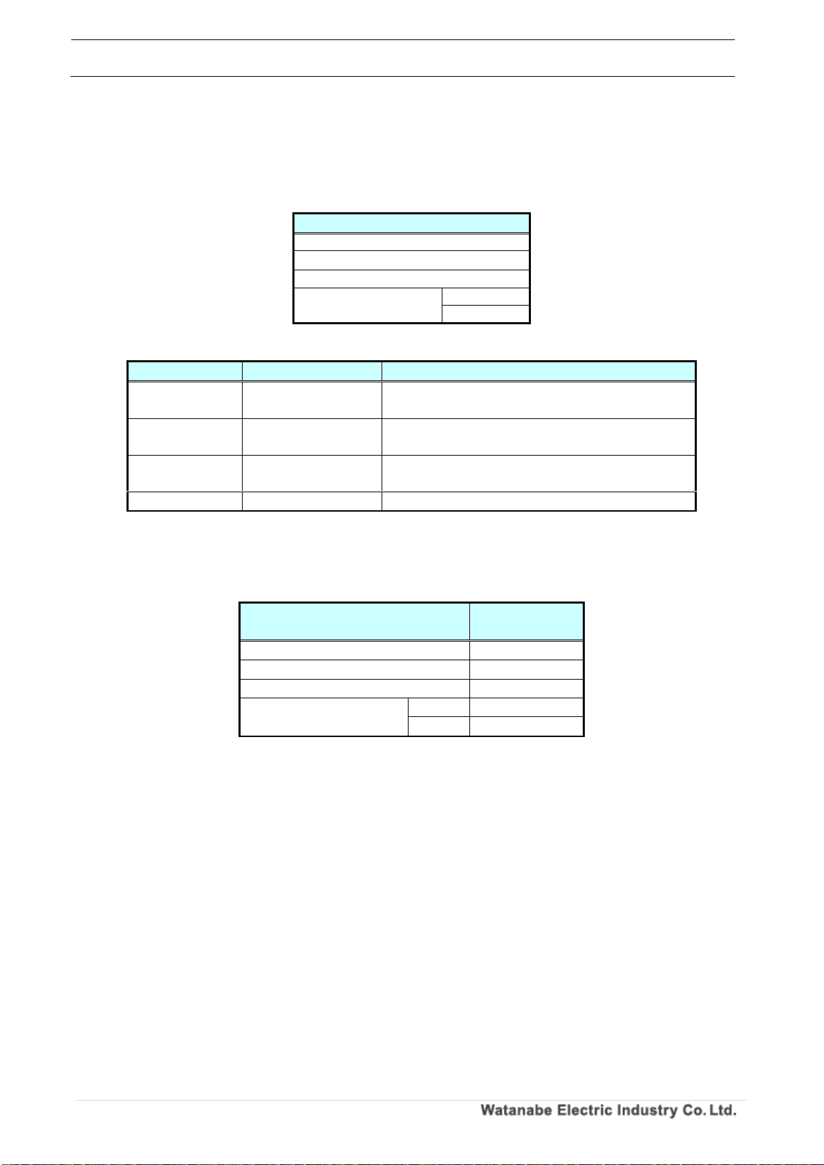
If there is an error in the message sent from the master, an error message is returned from the slave
(module).
When an error message is returned, check the transmission data.
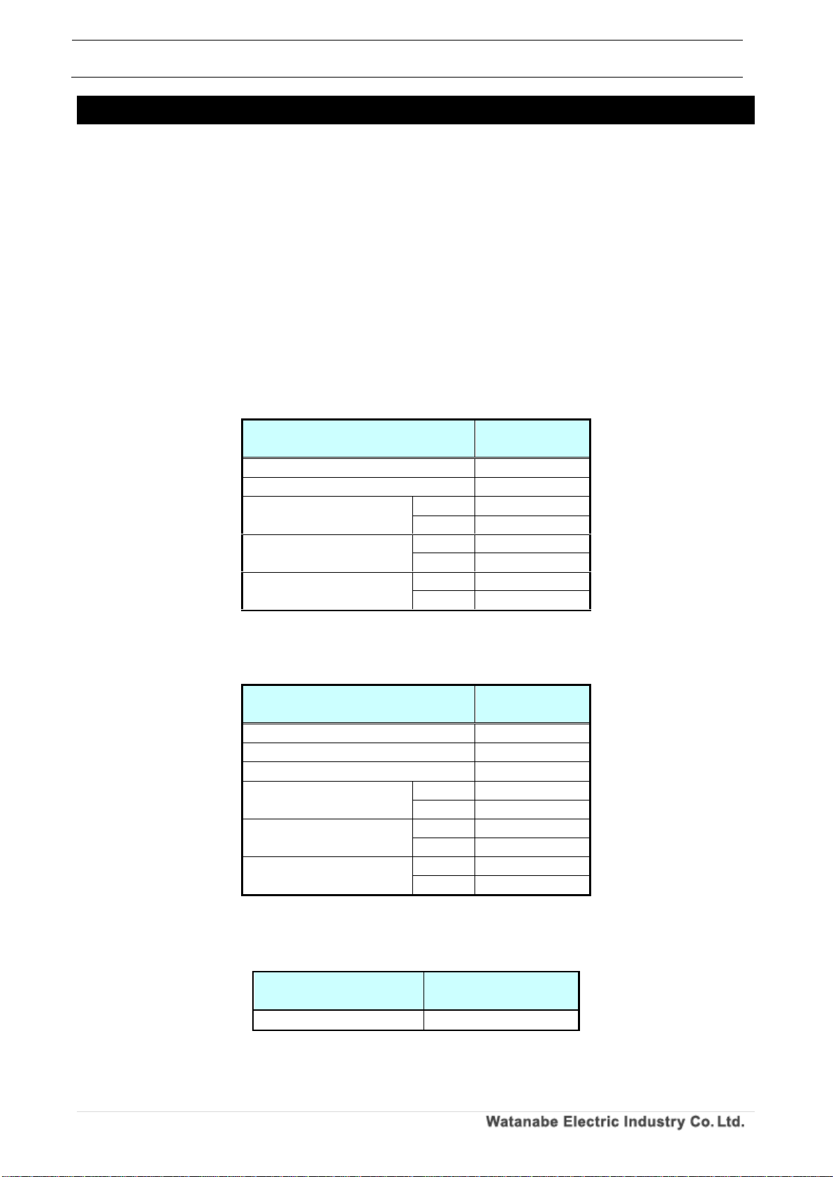
Table 3.19 Contents of error message (slave (module) → master)
na m e
Sl a ve I D
Re c ei ve d fu n ct io n c o d e + 8 0 H
Er r or c od e ( se e ta b le b e l ow )
Er r or c h e c k
(CRC- 16)
Lo w er
Up p e r
Table 3.20 Error code contents
Er r or c od e
Con te nt s
De s cr ip ti o n
01H
Fu n c t io n c o d e
de f ec t
Th e m od ul e r ec ei ve d a f un ct i o n c od e th a t
doe s no t c o r re sp on d.
02H
Ad d re ss p r o b le m
Th e m od ul e r ec ei ve d a n on - co m p l i a nt
ad d re ss .
03H
Nu m be r of d a t a
er r or s
Th e s pe ci f ie d nu mb e r o f d at a is t o o la rg e .
06H
Sl a ve b us y
Th e m od ul e i s bu sy .
◎Error example
Response in case an address error occurs in the function code 04H from the module with the slave ID
01H
Table 3.21 Example of received data in case of error
na m e
Re c e i ve d
da t a
Sl a ve I D
01H
Fu n c t io n c o d e
84H
Er r or c o de
02H
Er r or c h e c k
(CRC- 16)
Lo w er
C2 H
Up p e r
C1 H
Page 22
WPMZ Series Modbus communication instruction manual
IM-0862-02
Number of pages:109
21
4. Communication example
The actual communication example of each message is shown below.
4-1. WPMZ-5/6
4-1-1. Acquire measurement data
When acquiring measurement data, it is as follows.
1. Data acquisition communication
Here is an example of obtaining the instantaneous display value of pulse input A.
Pulse input A instantaneous display value is defined in the input register, so 04 H (input register
readout [read only address]) is used as the function code.
Puls e in p ut A inst a nta n eous disp l ay v alue acq u i siti on (a ddre ss: 0 1 91 H )
First, send a message from the master to the slave (module).
Since the data size is 4 bytes, the number of read words is 2.
Table 4.1 Pulse input A Acquire instantaneous display value [Send]
na m e
Tr a n s mi tt e d
da t a
Sl a ve I D
01H
Fu n c t io n c o d e
04H
Ad d re s s
Up p e r
01 H
Lo w er
91H
Nu m be r of w o r d s to
be re ad
Up p e r
00H
Lo w er
02 H
Er r or c h e c k
(CRC- 16)
Lo w er
21H
Up p e r
DAH
After that, 2 words of data are returned from the slave (module) to the master.
Table 4.2 Pulse input A Acquire instantaneous display value [Receive]
na m e
Re c e i ve d
da t a
Sl a ve I D
01H
Fu n c t io n c o d e
04H
Nu m be r o f by te s r ea d
04H
Da t a of t he fi rs t
wor d
Up p e r
00H
Lo w er
01 H
Da t a of t h e se co nd
wor d
Up p e r
E2H
Lo w er
40H
Er r or c h e c k
(CRC- 16)
Lo w er
E3 H
Up p e r
14H
The acquired data is continued for two words, and it is as follows.
Table 4.3 Acquired data
Read value
(hexadecimal number)
Decimal number
0001E240H
123456
Page 23
WPMZ Series Modbus communication instruction manual
IM-0862-02
Number of pages:109
22
4-1-2. Change control parameters
The simulation input / output control of the module is as follows.
1. Control parameter change communication
This example shows simulated output of the comparison output AL1.
Since the simulation output instruction of the comparison output AL1 is defined in the holding register,
10H (hold register consecutive writing) is used as the function code.
Comp a rat i ve o u tpu t AL1 simu l ated out p u t ( a ddre s s: 0 3 E8H )
First, send a message from the master to the slave (module).
Data write AL1 simulation output instruction: valid (0001H), indicated value: ON (0001H).
Since the number of words to be written is 2, the number of bytes to be written is 4.
Table 4.4 Comparative output AL1 simulated output [Send]
na m e
Tr a n s mi tt e d
da t a
Sl a ve I D
01H
Fu n c t io n c o d e
10H
St a rt a d d r es s
Up p e r
03 H
Lo w er
E8H
Th e n um be r o f da ta
Up p e r
00 H
Lo w er
02H
Nu m be r of b y te s
04H
Da t a of t he fi rs t
wor d
Up p e r
00H
Lo w er
01H
Da t a of t h e se co nd
wor d
Up p e r
00H
Lo w er
01 H
Er r or c h e c k
(CRC- 16)
Lo w er
78H
Up p e r
B1H
Then the slave (module) will respond to the master.
Table 4.5 Comparative output AL1 simulated output [Receive]
na m e
Re c e i ve d
da t a
Sl a ve I D
01H
Fu n c t io n c o d e
10H
Ad d re ss
Up p e r
03H
Lo w er
E8H
Th e n um be r o f da ta
Up p e r
00H
Lo w er
02 H
Er r or c h e c k
(CRC- 16)
Lo w er
C1H
Up p e r
B8H
Page 24
WPMZ Series Modbus communication instruction manual
IM-0862-02
Number of pages:109
23
4-1-3. Change setting parameters
To change the setting parameters, follow the steps below.
1. Setting permission communication
To change the setting value (address 0BC2H or later of the holding register), first specify setting
permission.
Function code is 10H (hold register consecutive writing) is used.
Sett i ng p ermi s sion ins t r uct i on ( a ddre s s: 0 BB8 H )
First, send a message from the master to the slave (module).
Data write setting permission (3333 CCCCH).
Since the number of words to be written is 2, the number of bytes to be written is 4.
Table 4.6 Setting permission instruction [transmission]
na m e
Tr a n s mi tt e d
da t a
Sl a ve I D
01H
Fu n c t io n c o d e
10H
St a rt a d d r es s
Up p e r
0B H
Lo w er
B8H
Th e n um be r o f da ta
Up p e r
00 H
Lo w er
02H
Nu m be r of b y te s
04H
Da t a of t h e fi rs t
wor d
Up p e r
33H
Lo w er
33H
Da t a of t h e se co nd
wor d
Up p e r
CCH
Lo w er
CCH
Er r or c h e c k
(CRC- 16)
Lo w er
20H
Up p e r
53H
Then the slave (module) will respond to the master.
When the following response is returned, the module is in the setting enable state.
Table 4.7 Setting permission instruction [reception]
名称
Re c e i ve d
da t a
Sl a ve I D
01H
Fu n c t io n c o d e
10H
Ad d re s s
Up p e r
0BH
Lo w er
B8H
Th e n um be r o f da ta
Up p e r
00H
Lo w er
02 H
Er r or c h e c k
(CRC- 16)
Lo w er
C3H
Up p e r
C9H
Page 25
WPMZ Series Modbus communication instruction manual
IM-0862-02
Number of pages:109
24
2. Setting value write communication
An example of changing "pulse input A pattern 1 input type" is shown below.
The function code is 06H (1-word holding register hold) or 10H (hold register continuous write).
Puls e in p ut A pat t ern 1 In put t y pe c han g e (a d d res s : 0B C 2H)
First, send a message from the master to the slave (module).
Below is an example of setting logic (0001H) for pulse input A pattern 1 input type.
Since the number of write words is 1, the write byte count is 2.
Table 4.8 Pulse input A pattern 1 input type write [transmit]
na m e
Tr a n s mi tt e d
da t a
Sl a ve I D
01H
Fu n c t io n c o d e
10H
St a rt a d d r es s
Up p e r
0B H
Lo w er
C2H
Th e n um be r o f da ta
Up p e r
00 H
Lo w er
01H
Nu m be r of b yt e s
02 H
Da t a of t h e fi rs t
wor d
Up p e r
00H
Lo w er
01H
Er r or c h e c k
(CRC- 16)
Lo w er
CDH
Up p e r
B2H
Then the slave (module) will respond to the master.
If you specify a value outside the range or there is an error in the address, it will be an error
response here, so you will need to redo the setting permission communication again.
Table 4.9 Pulse input A pattern 1 input type write [receive]
na m e
Re c e i ve d
da t a
Sl a ve I D
01H
Fu n c t io n c o d e
10H
Ad d re s s
Up p e r
0B H
Lo w er
C2H
Th e n um be r o f da ta
Up p e r
00 H
Lo w er
01H
Er r or c h e c k
(CRC- 16)
Lo w er
A2H
Up p e r
11H
Page 26
WPMZ Series Modbus communication instruction manual
IM-0862-02
Number of pages:109
25
3. Setting save communication
When saving the changed setting value, it instructs save setting.
Function code is 10H (hold register consecutive writing) is used.
Sett i ng s a ve i nst r ucti o n (a d d res s : 0B B 8H)
First, send a message from the master to the slave (module).
Write setting permission (00000000H) for data.
Since the number of words to be written is 2, the number of bytes to be written is 4.
Table 4.10 Setting save instruction [Send]
na m e
Tr a n s mi tt e d
da t a
Sl a ve I D
01H
Fu n c t io n c o d e
10H
St a rt a d d r es s
Up p e r
0B H
Lo w er
B8H
Th e n um be r o f da ta
Up p e r
00 H
Lo w er
02H
Nu m be r of b y te s
04 H
Da t a of t h e f i r s t
wor d
Up p e r
00H
Lo w er
00H
Da t a of t h e se co nd
wor d
Up p e r
00H
Lo w er
00H
Er r or c h e c k
(CRC- 16)
Lo w er
8AH
Up p e r
4DH
Then the slave (module) will respond to the master.
If it is not an error response, the setting value is updated normally.
In the case of an error response, it is necessary to redo the setting permission communication
again.
Table 4.11 Setting save instruction [reception]
na m e
Re c e i ve d
da t a
Sl a ve I D
01H
Fu n c t io n c o d e
10H
Ad d re s s
Up p e r
0B H
Lo w er
B8H
Th e n um be r o f da ta
Up p e r
00 H
Lo w er
02H
Er r or c h e c k
(CRC- 16)
Lo w er
C3H
Up p e r
C9H
Page 27
WPMZ Series Modbus communication instruction manual
IM-0862-02
Number of pages:109
26
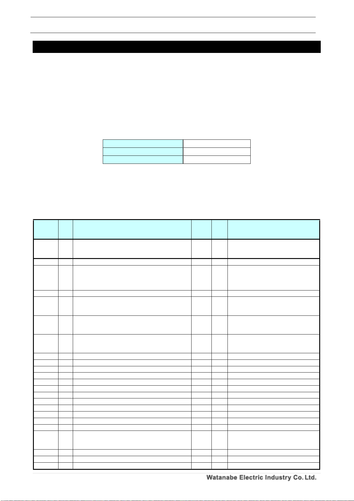
5. Address Map
Write the address map of each model.
5-1. WPMZ-5/6
This section describes the WPM-5/6 of the address map.
5-1-1. Setting and control parameters
1. Holding register
The hold register command is shown in the table below.
Table 5.1 Holding register command
Read command
03H
Write command
06H
Continuous write command
10H
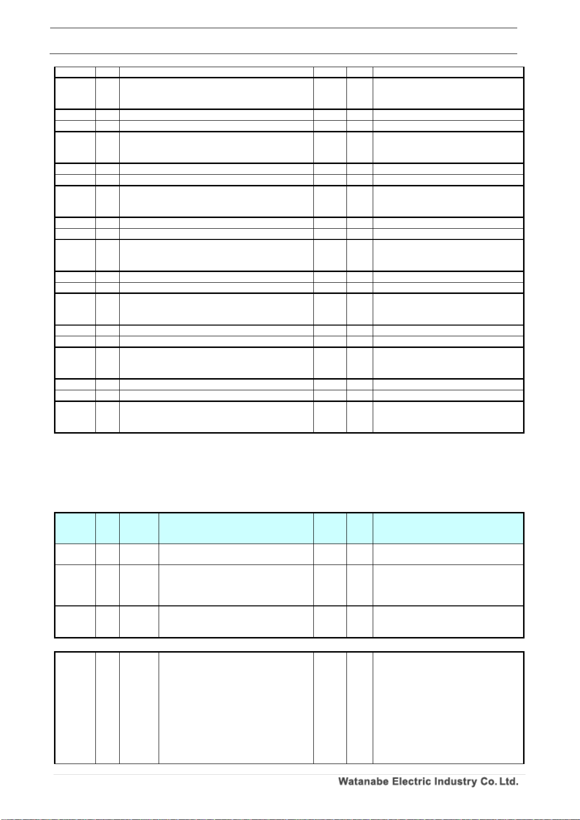
Con t r ol p a ram e ter s
The control parameters are as follows.
Please refer to "4-1-2. Change control parameters" when making mock input / output instruction
from control parameters.
Table 5.2 Control parameters
Communi
cation
address
CH
Contents
size
(byte)
R/W
The data
0000H
~
0065H
~
Reserve
~ ~
0066H
-
Pattern select indication
2
R/W
0000H:Disable、0001H:Enable
0067H
-
Pattern select indication value
2
R/W
0000H:pattern 1、0001H:pattern 2、
0002H:pattern 3、0003H:pattern 4、
0004H:pattern 5、0005H:pattern 6、
0006H:pattern 7、0007H:pattern 8
0068H
-
Relay reset indication
2
R/W
0000H:Disable、0001H:Enable
0069H
-
Integration reset A indication
2
R/W
0000H:Disable、0001H:Enable
※Automatically return to 0000H after
execution
006AH
-
Integration reset B indication
2
R/W
0000H:Disable、0001H:Enable
※Automatically return to 0000H after
execution
006BH
-
Integration reset A & B instruction
2
R/W
0000H:Disable、0001H:Enable
※Automatically return to 0000H after
execution
006CH
-
Measurement prohibited A indication
2
R/W
0000H:Disable、0001H:Enable
006DH
-
Measurement prohibited B indication
2
R/W
0000H:Disable、0001H:Enable
006EH
-
Measurement prohibited A & B indication
2
R/W
0000H:Disable、0001H:Enable
006FH
-
Present value holding A indication
2
R/W
0000H:Disable、0001H:Enable
0070H
-
Present value holding B indication
2
R/W
0000H:Disable、0001H:Enable
0071H
-
Current value holding A & B instruction
2
R/W
0000H:Disable、0001H:Enable
0072H
-
Maximum value holding A indication
2
R/W
0000H:Disable、0001H:Enable
0073H
-
Maximum value holding B indication
2
R/W
0000H:Disable、0001H:Enable
0074H
-
Maximum value holding A & B instruction
2
R/W
0000H:Disable、0001H:Enable
0075H
-
Minimum value holding A indication
2
R/W
0000H:Disable、0001H:Enable
0076H
-
Minimum value holding B indication
2
R/W
0000H:Disable、0001H:Enable
0077H
-
Minimum value holding A & B instruction
2
R/W
0000H:Disable、0001H:Enable
0078H
-
Display switching instruction
2
R/W
0000H:Disable、0001H:Enable
※Automatically return to 0000H after
execution
0079H
-
Trend holding instruction
2
R/W
0000H:Disable、0001H:Enable
007AH
-
Digital zero A instruction
2
R/W
0000H:Disable、0001H:Enable
007BH
-
Digital zero B instruction
2
R/W
0000H:Disable、0001H:Enable
Page 28
WPMZ Series Modbus communication instruction manual
IM-0862-02
Number of pages:109
27
007CH
-
Digital zero A & B instruction
2
R/W
0000H:Disable、0001H:Enable
007DH
~
03E7H
~
Reserve
~ ~
03E8H
AL1
Compare output instruction
2
R/W
0000H:Disable、0001H:Enable
03E9H
AL1
Comparative output indication value
2
R/W
0000H:OFF、0001H:ON
03EAH
~
0419H
~
Reserve
~ ~
041AH
AL2
Compare output instruction
2
R/W
※AL1 reference
041BH
AL2
Comparative output indication value
2
R/W
※AL1 reference
041CH
~
044BH
~
Reserve
~ ~
044CH
AL3
Compare output instruction
2
R/W
※AL1 reference
044DH
AL3
Comparative output indication value
2
R/W
※AL1 reference
044EH
~
047DH
~
Reserve
~ ~
047EH
AL4
Compare output instruction
2
R/W
※AL1 reference
047FH
AL4
Comparative output indication value
2
R/W
※AL1 reference
0480H
~
0513H
~
Reserve
~ ~
0514H
A
Pulse output indication
2
R/W
0000H:Disable、0001H:Enable
0515H
A
Pulse output indication value
2
R/W
0000H:OFF、0001H:ON
0516H
~
0545H
~
Reserve
~ ~
0546H
B
Pulse output indication
2
R/W
※Pulse output A reference
0547H
B
Pulse output indication value
2
R/W
※Pulse output A reference
0548H
~
0BB7H
~
Reserve
~ ~
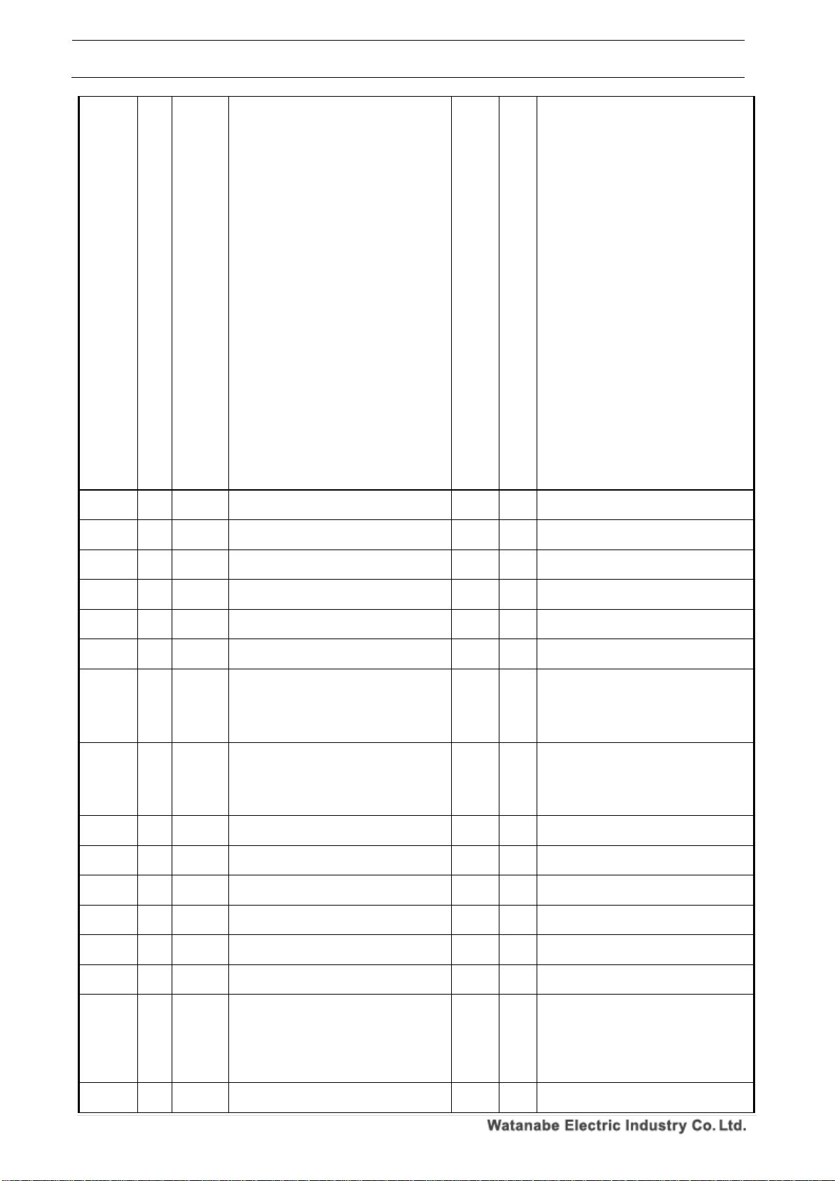
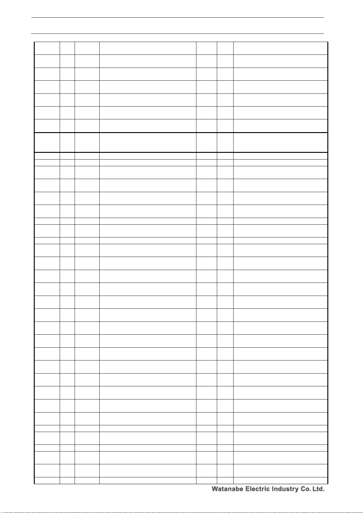
Sett i ng p aram e ter s
The setting parameters are as follows.
Refer to "4-1-3. Change setting parameters" when changing the setting parameters.
Table 5.3 Setting parameters
Communi
cation
address
CH
Pattern
Contents
size
(byte)
R/W
The data
0BB8H - -
Setting permission / save instruction
4
W
3333 CCCCH:Setting permission、
0000 0000H:Save instruction
0BBAH - -
Setting error contents
2
R
0000H: No error,
Other than 0000H: There is an error
※Error code Refer to "Table 5.4 reference
" for details
0BBBH
~
0BC1H
~ ~ Reserve
~ ~
-
0BC2H A 1
Pulse Input, input type
2
R/W
In case of general purpose pulse input type
0000H:Open collector、
0001H:Logic、
0002H: Zero cross,
0003 H: 2 Wire,
0004H: 2-PhaseOpen Collector * 1, 2,
0005H: 2-Phase Logic * 1, 2,
0006H: 2-Phase 2 Wire* 1, 2
In case of line driver pulse input type
0000H:Line driver
*1 It can not be set when the input B
Page 29

WPMZ Series Modbus communication instruction manual
IM-0862-02
Number of pages:109
28
model is "None".
*2 It can be set only when the series
model is "WPMZ - 6" and both input type
of A/B are [general purpose pulse input].
0BC3H A 1
Pulse input, input filter
2
R/W
In case of general purpose pulse input type
0000H: None, 0001H: 30 Hz,
0002 H: 1.5 kHz, 0003 H: 15 kHz
In case of line driver pulse input type
0000H: No filter
0BC4H A 1
Sensor power supply for general purpose
pulse input type
2
R/W
0000H:12V、0001H:24V
0BC5H A 1
Sensor power supply for line driver input
type
2
R/W
0000H:5V
0BC6H A 1
Pulse input, mantissa part of instantaneous
value display coefficient
4
R/W
0~999,999
0BC8H A 1
Pulse input, exponent part of instantaneous
value display coefficient
2
R/W
-9~9
0BC9H A 1
Pulse input, instantaneous unit time.
2
R/W
0000 H: Second,
0001 H: Minute,
0002 H: Hour
0BCAH A 1
Pulse input, instantaneous value Decimal
point position
2
R/W
0000H:None,
0001H:The lower right of the 2nd digit,
0002H:The lower right of the 3rd digit,
0003H:The lower right of the 4th digit,
0004H:The lower right of the 5th digit,
0005H:The lower right of the 6th digit
0BCBH A 1
Pulse input, instantaneous value display unit
2
R/W
0000H:None、
0002H:mA、
0004H:kA、
0006H:mV、
0008H:kV、
000AH:W、
000CH:MW、
000EH:mm、
0010H:m、
0012H:kΩ、
0014H:g、
0016H:N、
0018H:MN、
001AH:khan、
001CH:hPa、
001EH:kJ、
0020H:Hz、
0022H:MHz、
0024H:mm/s、
0026H:cm/min、
0028H:m/min、
002AH:m/s2、
002CH:m3/min、
002EH:kg/h、
0030H:kg/m3、
0032H:ℓ、
0034H:ℓ/min、
0036H:%、
0038H:%RH、
003AH:ph、
003CH:rpm、
003EH:inch、
0001H:µA、
0003H:A、
0005H:µV、
0007H:V、
0009H:VA、
000BH:kW、
000DH:µm、
000FH:cm、
0011H:Ω、
0013H:MΩ、
0015H:kg、
0017H:kN、
0019H:Pa、
001BH:Mpa、
001DH:J、
001FH:MJ、
0021H:kHz、
0023H:m3、
0025H:mm/min、
0027H:m/s、
0029H:m/h
002BH:m3/s、
002DH:m3/h、
002FH:kg/m2、
0031H:N/m2、
0033H:ℓ/s、
0035H:ℓ/h、
0037H:‰、
0039H:℃、
003BH:ppm、
003DH:t、
003FH:Custom unit
0BCCH A 1
Pulse input, instantaneous value display
Custom unit 1st character
2
R/W
0000H:None、
0002H:b、
0004H:d、
0006H:f、
0008H:h、
000AH:j、
000CH:l、
000EH:n、
0010H:p、
0012H:r、
0014H:t、
0001H:a、
0003H:c、
0005H:e、
0007H:g、
0009H:i、
000BH:k、
000DH:m、
000FH:o、
0011H:q、
0013H:s、
0015H:u、
Page 30
WPMZ Series Modbus communication instruction manual
IM-0862-02
Number of pages:109
29
0016H:v、
0018H:x、
001AH:z、
001CH:B、
001EH:D、
0020H:F、
0022H:H、
0024H:J、
0026H:L、
0028H:N、
002AH:P、
002CH:R、
002EH:T、
0030H:V、
0032H:X、
0034H:Z、
0036H:]、
0038H:)、
003AH:2、
003CH:1、
003EH:3、
0040H:µ、
0042H:g、
0044H:/、
0046H:%、
0048H:°、
004AH:”
0017H:w、
0019H:y、
001BH:A、
001DH:C、
001FH:E、
0021H:G、
0023H:I、
0025H:K、
0027H:M、
0029H:O
002BH:Q、
002DH:S、
002FH:U、
0031H:W、
0033H:Y、
0035H:[、
0037H:(、
0039H:1、
003BH:3、
003DH:2、
003FH:-、
0041H:Ω、
0043H:・、
0045H:ℓ、
0047H:‰、
0049H:’、
0BCDH A 1
Pulse input, instantaneous value display
Custom unit 2nd character
2
R/W
※Refer to "Pulse input, instantaneous
value display custom unit first character"
0BCEH A 1
Pulse input, instantaneous value display
Custom unit 3rd character
2
R/W
※Refer to "Pulse input, instantaneous
value display custom unit first character"
0BCFH A 1
Pulse input, instantaneous value display
Custom unit 4th character
2
R/W
※Refer to "Pulse input, instantaneous
value display custom unit first character"
0BD0H A 1
Pulse input, instantaneous value display
Custom unit 5th character
2
R/W
※Refer to "Pulse input, instantaneous
value display custom unit first character"
0BD1H A 1
Pulse input, instantaneous value display
Custom unit 6th character
2
R/W
※Refer to "Pulse input, instantaneous
value display custom unit first character"
0BD2H A 1
Pulse input, instantaneous value auto zero
time
2
R/W
0~9999[×0.01 Seconds]
0BD3H A 1
Pulse input, instantaneous value moving
average
2
R/W
0000 H: None, 0001 H: 2 times,
0002 H: 3 times, 0003 H: 4 times,
0004 H: 5 times, 0005 H: 6 times,
0006 H: 7 times, 0007 H: 8 times,
0008 H: 9 times
0BD4H A 1
Pulse input, instantaneous value simple
average
2
R/W
0000 H: None, 0001 H: 2 times,
0002 H: 4 times, 0003 H: 8 times,
0004 H: 16 times, 0005 H: 32 times,
0006 H: 64 times, 0007 H: 128 times,
0008 H: 256 times
0BD5H A 1
Pulse input, instantaneous value display
step
2
R/W
0000H: None, 0001H: 5 steps,
0002H: 10 steps
0BD6H A 1
Pulse input, mantissa part of totalized value
display coefficient
4
R/W
0~999,999
0BD8H A 1
Pulse input, mantissa part of totalized value
display value coefficient
2
R/W
-9~9
0BD9H A 1
Pulse input, mantissa part of totalized value
default value
4
R/W
-999,999~999,999
0BDBH A 1
Pulse input, exponent part of totalized value
default value
2
R/W
-9~9
0BDCH A 1
Pulse input, total calculation direction
2
R/W
0000H: AddToDefault,
0001H: SubFromDefault
0BDDH A 1
Pulse input, totalized value Decimal point
position
2
R/W
0000H:None,
0001H:The lower right of the 2nd digit,
0002H:The lower right of the 3rd digit,
0003H:The lower right of the 4th digit,
0004H:The lower right of the 5th digit,
0005H:The lower right of the 6th digit
0BDEH A 1
Pulse input, totalized value display unit
2
R/W
※Refer to "Pulse input, instantaneous
value display unit"
Page 31
WPMZ Series Modbus communication instruction manual
IM-0862-02
Number of pages:109
30
0BDFH A 1
Pulse input, totalized value display Custom
unit 1st character
2
R/W
※Refer to "Pulse input, instantaneous
value display Custom unit first character"
0BE0H A 1
Pulse input, totalized value display Custom
unit 2nd character
2
R/W
※Refer to "Pulse input, instantaneous
value display Custom unit first character"
0BE1H A 1
Pulse input, totalized value display Custom
unit 3rd character
2
R/W
※Refer to "Pulse input, instantaneous
value display Custom unit first character"
0BE2H A 1
Pulse input, totalized value display Custom
unit 4th character
2
R/W
※Refer to "Pulse input, instantaneous
value display Custom unit first character"
0BE3H A 1
Pulse input, totalized value display Custom
unit 5th character
2
R/W
※Refer to "Pulse input, instantaneous
value display Custom unit first character"
0BE4H A 1
Pulse input, totalized value display Custom
unit 6th character
2
R/W
※Refer to "Pulse input, instantaneous
value display Custom unit first character"
0BE5H A 1
Pulse input, totalized value overrun count
2
R/W
0000 H: None, 0001 H: 999 times,
0002 H: Endless
0BE6H
~
0BF3H
~ ~ Reserve
~ ~
0BF4H A 2
Pulse Input, input type
2
R/W
※Refer to Pattern1
0BF5H A 2
Pulse input, input filter
2
R/W
※Refer to Pattern1
0BF6H A 2
Sensor power supply for general purpose
pulse input type
2
R/W
※Refer to Pattern1
0BF7H A 2
Sensor power supply for line driver input
type
2
R/W
※Refer to Pattern1
0BF8H A 2
Pulse input, mantissa part of instantaneous
value display coefficient
4
R/W
※Refer to Pattern1
0BFAH A 2
Pulse input, exponent part of instantaneous
value display coefficient
2
R/W
※Refer to Pattern1
0BFBH A 2
Pulse input, instantaneous unit time.
2
R/W
※Refer to Pattern1
0BFCH A 2
Pulse input, instantaneous value Decimal
point position
2
R/W
※Refer to Pattern1
0BFDH A 2
Pulse input, instantaneous value display unit
2
R/W
※Refer to Pattern1
0BFEH A 2
Pulse input, instantaneous value display
Custom unit 1st character
2
R/W
※Refer to Pattern1
0BFFH A 2
Pulse input, instantaneous value display
Custom unit 2nd character
2
R/W
※Refer to Pattern1
0C00H A 2
Pulse input, instantaneous value display
Custom unit 3rd character
2
R/W
※Refer to Pattern1
0C01H A 2
Pulse input, instantaneous value display
Custom unit 4th character
2
R/W
※Refer to Pattern1
0C02H A 2
Pulse input, instantaneous value display
Custom unit 5th character
2
R/W
※Refer to Pattern1
0C03H A 2
Pulse input, instantaneous value display
Custom unit 6th character
2
R/W
※Refer to Pattern1
0C04H A 2
Pulse input, instantaneous value auto zero
time
2
R/W
※Refer to Pattern1
0C05H A 2
Pulse input, instantaneous value moving
average
2
R/W
※Refer to Pattern1
0C06H A 2
Pulse input, instantaneous value simple
average
2
R/W
※Refer to Pattern1
0C07H A 2
Pulse input, instantaneous value display
step
2
R/W
※Refer to Pattern1
0C08H A 2
Pulse input, mantissa part of totalized value
display coefficient
4
R/W
※Refer to Pattern1
0C0AH A 2
Pulse input, mantissa part of totalized value
display value coefficient
2
R/W
※Refer to Pattern1
0C0BH A 2
Pulse input, mantissa part of totalized value
default value
4
R/W
※Refer to Pattern1
0C0DH A 2
Pulse input, exponent part of totalized value
default value
2
R/W
※Refer to Pattern1
0C0EH A 2
Pulse input, total calculation direction
2
R/W
※Refer to Pattern1
0C0FH A 2
Pulse input, totalized value Decimal point
position
2
R/W
※Refer to Pattern1
0C10H A 2
Pulse input, totalized value display unit
2
R/W
※Refer to Pattern1
0C11H A 2
Pulse input, totalized value display Custom
unit 1st character
2
R/W
※Refer to Pattern1
0C12H A 2
Pulse input, totalized value display Custom
unit 2nd character
2
R/W
※Refer to Pattern1
0C13H A 2
Pulse input, totalized value display Custom
2
R/W
※Refer to Pattern1
Page 32
WPMZ Series Modbus communication instruction manual
IM-0862-02
Number of pages:109
31
unit 3rd character
0C14H A 2
Pulse input, totalized value display Custom
unit 4th character
2
R/W
※Refer to Pattern1
0C15H A 2
Pulse input, totalized value display Custom
unit 5th character
2
R/W
※Refer to Pattern1
0C16H A 2
Pulse input, totalized value display Custom
unit 6th character
2
R/W
※Refer to Pattern1
0C17H A 2
Pulse input, totalized value overrun count
2
R/W
※Refer to Pattern1
0C18H
~
0C25H
~ ~ Reserve
~
~
0C26H A 3
Pulse Input, input type
2
R/W
※Refer to Pattern1
0C27H A 3
Pulse input, input filter
2
R/W
※Refer to Pattern1
0C28H A 3
Sensor power supply for general purpose
pulse input type
2
R/W
※Refer to Pattern1
0C29H A 3
Sensor power supply for line driver input
type
2
R/W
※Refer to Pattern1
0C2AH A 3
Pulse input, mantissa part of instantaneous
value display coefficient
4
R/W
※Refer to Pattern1
0C2CH A 3
Pulse input, exponent part of instantaneous
value display coefficient
2
R/W
※Refer to Pattern1
0C2DH A 3
Pulse input, instantaneous unit time.
2
R/W
※Refer to Pattern1
0C2EH A 3
Pulse input, instantaneous value Decimal
point position
2
R/W
※Refer to Pattern1
0C2FH A 3
Pulse input, instantaneous value display unit
2
R/W
※Refer to Pattern1
0C30H A 3
Pulse input, instantaneous value display
Custom unit 1st character
2
R/W
※Refer to Pattern1
0C31H A 3
Pulse input, instantaneous value display
Custom unit 2nd character
2
R/W
※Refer to Pattern1
0C32H A 3
Pulse input, instantaneous value display
Custom unit 3rd character
2
R/W
※Refer to Pattern1
0C33H A 3
Pulse input, instantaneous value display
Custom unit 4th character
2
R/W
※Refer to Pattern1
0C34H A 3
Pulse input, instantaneous value display
Custom unit 5th character
2
R/W
※Refer to Pattern1
0C35H A 3
Pulse input, instantaneous value display
Custom unit 6th character
2
R/W
※Refer to Pattern1
0C36H A 3
Pulse input, instantaneous value auto zero
time
2
R/W
※Refer to Pattern1
0C37H A 3
Pulse input, instantaneous value moving
average
2
R/W
※Refer to Pattern1
0C38H A 3
Pulse input, instantaneous value simple
average
2
R/W
※Refer to Pattern1
0C39H A 3
Pulse input, instantaneous value display
step
2
R/W
※Refer to Pattern1
0C3AH A 3
Pulse input, mantissa part of totalized value
display coefficient
4
R/W
※Refer to Pattern1
0C3CH A 3
Pulse input, mantissa part of totalized value
display value coefficient
2
R/W
※Refer to Pattern1
0C3DH A 3
Pulse input, mantissa part of totalized value
default value
4
R/W
※Refer to Pattern1
0C3FH A 3
Pulse input, exponent part of totalized value
default value
2
R/W
※Refer to Pattern1
0C40H A 3
Pulse input, total calculation direction
2
R/W
※Refer to Pattern1
0C41H A 3
Pulse input, totalized value Decimal point
position
2
R/W
※Refer to Pattern1
0C42H A 3
Pulse input, totalized value display unit
2
R/W
※Refer to Pattern1
0C43H A 3
Pulse input, totalized value display Custom
unit 1st character
2
R/W
※Refer to Pattern1
0C44H A 3
Pulse input, totalized value display Custom
unit 2nd character
2
R/W
※Refer to Pattern1
0C45H A 3
Pulse input, totalized value display Custom
unit 3rd character
2
R/W
※Refer to Pattern1
0C46H A 3
Pulse input, totalized value display Custom
unit 4th character
2
R/W
※Refer to Pattern1
0C47H A 3
Pulse input, totalized value display Custom
unit 5th character
2
R/W
※Refer to Pattern1
0C48H A 3
Pulse input, totalized value display Custom
2
R/W
※Refer to Pattern1
Page 33
WPMZ Series Modbus communication instruction manual
IM-0862-02
Number of pages:109
32
unit 6th character
0C49H A 3
Pulse input, totalized value overrun count
2
R/W
※Refer to Pattern1
0C50H
~
0C57H
~ ~ Reserve
~
~
0C58H A 4
Pulse Input, input type
2
R/W
※Refer to Pattern1
0C59H A 4
Pulse input, input filter
2
R/W
※Refer to Pattern1
0C5AH A 4
Sensor power supply for general purpose
pulse input type
2
R/W
※Refer to Pattern1
0C5BH A 4
Sensor power supply for line driver input
type
2
R/W
※Refer to Pattern1
0C5CH A 4
Pulse input, mantissa part of instantaneous
value display coefficient
4
R/W
※Refer to Pattern1
0C5EH A 4
Pulse input, exponent part of instantaneous
value display coefficient
2
R/W
※Refer to Pattern1
0C5FH A 4
Pulse input, instantaneous unit time.
2
R/W
※Refer to Pattern1
0C60H A 4
Pulse input, instantaneous value Decimal
point position
2
R/W
※Refer to Pattern1
0C61H A 4
Pulse input, instantaneous value display unit
2
R/W
※Refer to Pattern1
0C62H A 4
Pulse input, instantaneous value display
Custom unit 1st character
2
R/W
※Refer to Pattern1
0C63H A 4
Pulse input, instantaneous value display
Custom unit 2nd character
2
R/W
※Refer to Pattern1
0C64H A 4
Pulse input, instantaneous value display
Custom unit 3rd character
2
R/W
※Refer to Pattern1
0C65H A 4
Pulse input, instantaneous value display
Custom unit 4th character
2
R/W
※Refer to Pattern1
0C66H A 4
Pulse input, instantaneous value display
Custom unit 5th character
2
R/W
※Refer to Pattern1
0C67H A 4
Pulse input, instantaneous value display
Custom unit 6th character
2
R/W
※Refer to Pattern1
0C68H A 4
Pulse input, instantaneous value auto zero
time
2
R/W
※Refer to Pattern1
0C69H A 4
Pulse input, instantaneous value moving
average
2
R/W
※Refer to Pattern1
0C6AH A 4
Pulse input, instantaneous value simple
average
2
R/W
※Refer to Pattern1
0C6BH A 4
Pulse input, instantaneous value display
step
2
R/W
※Refer to Pattern1
0C6CH A 4
Pulse input, mantissa part of totalized value
display coefficient
4
R/W
※Refer to Pattern1
0C6EH A 4
Pulse input, mantissa part of totalized value
display value coefficient
2
R/W
※Refer to Pattern1
0C6FH A 4
Pulse input, mantissa part of totalized value
default value
4
R/W
※Refer to Pattern1
0C71H A 4
Pulse input, exponent part of totalized value
default value
2
R/W
※Refer to Pattern1
0C72H A 4
Pulse input, total calculation direction
2
R/W
※Refer to Pattern1
0C73H A 4
Pulse input, totalized value Decimal point
position
2
R/W
※Refer to Pattern1
0C74H A 4
Pulse input, totalized value display unit
2
R/W
※Refer to Pattern1
0C75H A 4
Pulse input, totalized value display Custom
unit 1st character
2
R/W
※Refer to Pattern1
0C76H A 4
Pulse input, totalized value display Custom
unit 2nd character
2
R/W
※Refer to Pattern1
0C77H A 4
Pulse input, totalized value display Custom
unit 3rd character
2
R/W
※Refer to Pattern1
0C78H A 4
Pulse input, totalized value display Custom
unit 4th character
2
R/W
※Refer to Pattern1
0C79H A 4
Pulse input, totalized value display Custom
unit 5th character
2
R/W
※Refer to Pattern1
0C7AH A 4
Pulse input, totalized value display Custom
unit 6th character
2
R/W
※Refer to Pattern1
0C7BH A 4
Pulse input, totalized value overrun count
2
R/W
※Refer to Pattern1
0C7CH
~
0C8BH
~ ~ Reserve
~
~
Page 34
WPMZ Series Modbus communication instruction manual
IM-0862-02
Number of pages:109
33
0C8AH A 5
Pulse Input, input type
2
R/W
※Refer to Pattern1
0C8BH A 5
Pulse input, input filter
2
R/W
※Refer to Pattern1
0C8CH A 5
Sensor power supply for general purpose
pulse input type
2
R/W
※Refer to Pattern1
0C8DH A 5
Sensor power supply for line driver input
type
2
R/W
※Refer to Pattern1
0C8EH A 5
Pulse input, mantissa part of instantaneous
value display coefficient
4
R/W
※Refer to Pattern1
0C90H A 5
Pulse input, exponent part of instantaneous
value display coefficient
2
R/W
※Refer to Pattern1
0C91H A 5
Pulse input, instantaneous unit time.
2
R/W
※Refer to Pattern1
0C92H A 5
Pulse input, instantaneous value Decimal
point position
2
R/W
※Refer to Pattern1
0C93H A 5
Pulse input, instantaneous value display unit
2
R/W
※Refer to Pattern1
0C94H A 5
Pulse input, instantaneous value display
Custom unit 1st character
2
R/W
※Refer to Pattern1
0C95H A 5
Pulse input, instantaneous value display
Custom unit 2nd character
2
R/W
※Refer to Pattern1
0C96H A 5
Pulse input, instantaneous value display
Custom unit 3rd character
2
R/W
※Refer to Pattern1
0C97H A 5
Pulse input, instantaneous value display
Custom unit 4th character
2
R/W
※Refer to Pattern1
0C98H A 5
Pulse input, instantaneous value display
Custom unit 5th character
2
R/W
※Refer to Pattern1
0C99H A 5
Pulse input, instantaneous value display
Custom unit 6th character
2
R/W
※Refer to Pattern1
0C9AH A 5
Pulse input, instantaneous value auto zero
time
2
R/W
※Refer to Pattern1
0C9BH A 5
Pulse input, instantaneous value moving
average
2
R/W
※Refer to Pattern1
0C9CH A 5
Pulse input, instantaneous value simple
average
2
R/W
※Refer to Pattern1
0C9DH A 5
Pulse input, instantaneous value display
step
2
R/W
※Refer to Pattern1
0C9EH A 5
Pulse input, mantissa part of totalized value
display coefficient
4
R/W
※Refer to Pattern1
0CA0H A 5
Pulse input, mantissa part of totalized value
display value coefficient
2
R/W
※Refer to Pattern1
0CA1H A 5
Pulse input, mantissa part of totalized value
default value
4
R/W
※Refer to Pattern1
0CA3H A 5
Pulse input, exponent part of totalized value
default value
2
R/W
※Refer to Pattern1
0CA4H A 5
Pulse input, total calculation direction
2
R/W
※Refer to Pattern1
0CA5H A 5
Pulse input, totalized value Decimal point
position
2
R/W
※Refer to Pattern1
0CA6H A 5
Pulse input, totalized value display unit
2
R/W
※Refer to Pattern1
0CA7H A 5
Pulse input, totalized value display Custom
unit 1st character
2
R/W
※Refer to Pattern1
0CA8H A 5
Pulse input, totalized value display Custom
unit 2nd character
2
R/W
※Refer to Pattern1
0CA9H A 5
Pulse input, totalized value display Custom
unit 3rd character
2
R/W
※Refer to Pattern1
0CAAH A 5
Pulse input, totalized value display Custom
unit 4th character
2
R/W
※Refer to Pattern1
0CABH A 5
Pulse input, totalized value display Custom
unit 5th character
2
R/W
※Refer to Pattern1
0CACH A 5
Pulse input, totalized value display Custom
unit 6th character
2
R/W
※Refer to Pattern1
0CADH A 5
Pulse input, totalized value overrun count
2
R/W
※Refer to Pattern1
0CAEH
~
0CBBH
~ ~ Reserve
~
~
0CBCH A 6
Pulse Input, input type
2
R/W
※Refer to Pattern1
0CBDH A 6
Pulse input, input filter
2
R/W
※Refer to Pattern1
0CBEH A 6
Sensor power supply for general purpose
pulse input type
2
R/W
※Refer to Pattern1
0CBFH A 6
Sensor power supply for line driver input
2
R/W
※Refer to Pattern1
Page 35
WPMZ Series Modbus communication instruction manual
IM-0862-02
Number of pages:109
34
type
0CC0H A 6
Pulse input, mantissa part of instantaneous
value display coefficient
4
R/W
※Refer to Pattern1
0CC2H A 6
Pulse input, exponent part of instantaneous
value display coefficient
2
R/W
※Refer to Pattern1
0CC3H A 6
Pulse input, instantaneous unit time.
2
R/W
※Refer to Pattern1
0CC4H A 6
Pulse input, instantaneous value Decimal
point position
2
R/W
※Refer to Pattern1
0CC5H A 6
Pulse input, instantaneous value display unit
2
R/W
※Refer to Pattern1
0CC6H A 6
Pulse input, instantaneous value display
Custom unit 1st character
2
R/W
※Refer to Pattern1
0CC7H A 6
Pulse input, instantaneous value display
Custom unit 2nd character
2
R/W
※Refer to Pattern1
0CC8H A 6
Pulse input, instantaneous value display
Custom unit 3rd character
2
R/W
※Refer to Pattern1
0CC9H A 6
Pulse input, instantaneous value display
Custom unit 4th character
2
R/W
※Refer to Pattern1
0CCAH A 6
Pulse input, instantaneous value display
Custom unit 5th character
2
R/W
※Refer to Pattern1
0CCBH A 6
Pulse input, instantaneous value display
Custom unit 6th character
2
R/W
※Refer to Pattern1
0CCCH A 6
Pulse input, instantaneous value auto zero
time
2
R/W
※Refer to Pattern1
0CCDH A 6
Pulse input, instantaneous value moving
average
2
R/W
※Refer to Pattern1
0CCEH A 6
Pulse input, instantaneous value simple
average
2
R/W
※Refer to Pattern1
0CCFH A 6
Pulse input, instantaneous value display
step
2
R/W
※Refer to Pattern1
0CD0H A 6
Pulse input, mantissa part of totalized value
display coefficient
4
R/W
※Refer to Pattern1
0CD2H A 6
Pulse input, mantissa part of totalized value
display value coefficient
2
R/W
※Refer to Pattern1
0CD3H A 6
Pulse input, mantissa part of totalized value
default value
4
R/W
※Refer to Pattern1
0CD5H A 6
Pulse input, exponent part of totalized value
default value
2
R/W
※Refer to Pattern1
0CD6H A 6
Pulse input, total calculation direction
2
R/W
※Refer to Pattern1
0CD7H A 6
Pulse input, totalized value Decimal point
position
2
R/W
※Refer to Pattern1
0CD8H A 6
Pulse input, totalized value display unit
2
R/W
※Refer to Pattern1
0CD9H A 6
Pulse input, totalized value display Custom
unit 1st character
2
R/W
※Refer to Pattern1
0CDAH A 6
Pulse input, totalized value display Custom
unit 2nd character
2
R/W
※Refer to Pattern1
0CDBH A 6
Pulse input, totalized value display Custom
unit 3rd character
2
R/W
※Refer to Pattern1
0CDCH A 6
Pulse input, totalized value display Custom
unit 4th character
2
R/W
※Refer to Pattern1
0CDDH A 6
Pulse input, totalized value display Custom
unit 5th character
2
R/W
※Refer to Pattern1
0CDEH A 6
Pulse input, totalized value display Custom
unit 6th character
2
R/W
※Refer to Pattern1
0CDFH A 6
Pulse input, totalized value overrun count
2
R/W
※Refer to Pattern1
0CE0H
~
0CEDH
~ ~ Reserve
~ ~ ※Refer to Pattern1
0CEEH A 7
Pulse Input, input type
2
R/W
※Refer to Pattern1
0CEFH A 7
Pulse input, input filter
2
R/W
※Refer to Pattern1
0CF0H A 7
Sensor power supply for general purpose
pulse input type
2
R/W
※Refer to Pattern1
0CF1H A 7
Sensor power supply for line driver input
type
2
R/W
※Refer to Pattern1
0CF2H A 7
Pulse input, mantissa part of instantaneous
value display coefficient
4
R/W
※Refer to Pattern1
0CF4H A 7
Pulse input, exponent part of instantaneous
value display coefficient
2
R/W
※Refer to Pattern1
0CF5H A 7
Pulse input, instantaneous unit time.
2
R/W
※Refer to Pattern1
Page 36
WPMZ Series Modbus communication instruction manual
IM-0862-02
Number of pages:109
35
0CF6H A 7
Pulse input, instantaneous value Decimal
point position
2
R/W
※Refer to Pattern1
0CF7H A 7
Pulse input, instantaneous value display unit
2
R/W
※Refer to Pattern1
0CF8H A 7
Pulse input, instantaneous value display
Custom unit 1st character
2
R/W
※Refer to Pattern1
0CF9H A 7
Pulse input, instantaneous value display
Custom unit 2nd character
2
R/W
※Refer to Pattern1
0CFAH A 7
Pulse input, instantaneous value display
Custom unit 3rd character
2
R/W
※Refer to Pattern1
0CFBH A 7
Pulse input, instantaneous value display
Custom unit 4th character
2
R/W
※Refer to Pattern1
0CFCH A 7
Pulse input, instantaneous value display
Custom unit 5th character
2
R/W
※Refer to Pattern1
0CFDH A 7
Pulse input, instantaneous value display
Custom unit 6th character
2
R/W
※Refer to Pattern1
0CFEH A 7
Pulse input, instantaneous value auto zero
time
2
R/W
※Refer to Pattern1
0CFFH A 7
Pulse input, instantaneous value moving
average
2
R/W
※Refer to Pattern1
0D00H A 7
Pulse input, instantaneous value simple
average
2
R/W
※Refer to Pattern1
0D01H A 7
Pulse input, instantaneous value display
step
2
R/W
※Refer to Pattern1
0D02H A 7
Pulse input, mantissa part of totalized value
display coefficient
4
R/W
※Refer to Pattern1
0D04H A 7
Pulse input, mantissa part of totalized value
display value coefficient
2
R/W
※Refer to Pattern1
0D05H A 7
Pulse input, mantissa part of totalized value
default value
4
R/W
※Refer to Pattern1
0D07H A 7
Pulse input, exponent part of totalized value
default value
2
R/W
※Refer to Pattern1
0D08H A 7
Pulse input, total calculation direction
2
R/W
※Refer to Pattern1
0D09H A 7
Pulse input, totalized value Decimal point
position
2
R/W
※Refer to Pattern1
0D0AH A 7
Pulse input, totalized value display unit
2
R/W
※Refer to Pattern1
0D0BH A 7
Pulse input, totalized value display Custom
unit 1st character
2
R/W
※Refer to Pattern1
0D0CH A 7
Pulse input, totalized value display Custom
unit 2nd character
2
R/W
※Refer to Pattern1
0D0DH A 7
Pulse input, totalized value display Custom
unit 3rd character
2
R/W
※Refer to Pattern1
0D0EH A 7
Pulse input, totalized value display Custom
unit 4th character
2
R/W
※Refer to Pattern1
0D0FH A 7
Pulse input, totalized value display Custom
unit 5th character
2
R/W
※Refer to Pattern1
0D10H A 7
Pulse input, totalized value display Custom
unit 6th character
2
R/W
※Refer to Pattern1
0D11H A 7
Pulse input, totalized value overrun count
2
R/W
※Refer to Pattern1
0D12H
~
0D1FH
~ ~ Reserve
~
~
0D20H A 8
Pulse Input, input type
2
R/W
※Refer to Pattern1
0D21H A 8
Pulse input, input filter
2
R/W
※Refer to Pattern1
0D22H A 8
Sensor power supply for general purpose
pulse input type
2
R/W
※Refer to Pattern1
0D23H A 8
Sensor power supply for line driver input
type
2
R/W
※Refer to Pattern1
0D24H A 8
Pulse input, mantissa part of instantaneous
value display coefficient
4
R/W
※Refer to Pattern1
0D26H A 8
Pulse input, exponent part of instantaneous
value display coefficient
2
R/W
※Refer to Pattern1
0D27H A 8
Pulse input, instantaneous unit time.
2
R/W
※Refer to Pattern1
0D28H A 8
Pulse input, instantaneous value Decimal
point position
2
R/W
※Refer to Pattern1
0D29H A 8
Pulse input, instantaneous value display unit
2
R/W
※Refer to Pattern1
0D2AH A 8
Pulse input, instantaneous value display
Custom unit 1st character
2
R/W
※Refer to Pattern1
0D2BH A 8
Pulse input, instantaneous value display
2
R/W
※Refer to Pattern1
Page 37
WPMZ Series Modbus communication instruction manual
IM-0862-02
Number of pages:109
36
Custom unit 2nd character
0D2CH A 8
Pulse input, instantaneous value display
Custom unit 3rd character
2
R/W
※Refer to Pattern1
0D2DH A 8
Pulse input, instantaneous value display
Custom unit 4th character
2
R/W
※Refer to Pattern1
0D2EH A 8
Pulse input, instantaneous value display
Custom unit 5th character
2
R/W
※Refer to Pattern1
0D2FH A 8
Pulse input, instantaneous value display
Custom unit 6th character
2
R/W
※Refer to Pattern1
0D30H A 8
Pulse input, instantaneous value auto zero
time
2
R/W
※Refer to Pattern1
0D31H A 8
Pulse input, instantaneous value moving
average
2
R/W
※Refer to Pattern1
0D32H A 8
Pulse input, instantaneous value simple
average
2
R/W
※Refer to Pattern1
0D33H A 8
Pulse input, instantaneous value display
step
2
R/W
※Refer to Pattern1
0D34H A 8
Pulse input, mantissa part of totalized value
display coefficient
4
R/W
※Refer to Pattern1
0D36H A 8
Pulse input, mantissa part of totalized value
display value coefficient
2
R/W
※Refer to Pattern1
0D37H A 8
Pulse input, mantissa part of totalized value
default value
4
R/W
※Refer to Pattern1
0D39H A 8
Pulse input, exponent part of totalized value
default value
2
R/W
※Refer to Pattern1
0D3AH A 8
Pulse input, total calculation direction
2
R/W
※Refer to Pattern1
0D3BH A 8
Pulse input, totalized value Decimal point
position
2
R/W
※Refer to Pattern1
0D3CH A 8
Pulse input, totalized value display unit
2
R/W
※Refer to Pattern1
0D3DH A 8
Pulse input, totalized value display Custom
unit 1st character
2
R/W
※Refer to Pattern1
0D3EH A 8
Pulse input, totalized value display Custom
unit 2nd character
2
R/W
※Refer to Pattern1
0D3FH A 8
Pulse input, totalized value display Custom
unit 3rd character
2
R/W
※Refer to Pattern1
0D40H A 8
Pulse input, totalized value display Custom
unit 4th character
2
R/W
※Refer to Pattern1
0D41H A 8
Pulse input, totalized value display Custom
unit 5th character
2
R/W
※Refer to Pattern1
0D42H A 8
Pulse input, totalized value display Custom
unit 6th character
2
R/W
※Refer to Pattern1
0D43H A 8
Pulse input, totalized value overrun count
2
R/W
※Refer to Pattern1
0D44H
~
0D51H
~ ~ Reserve
~
~
0D52H B 1
Pulse Input, input type
2
R/W
In case of general purpose pulse input type
0000H: Open collector,
0001H: Logic,
0002H: Zero cross,
0003 H: 2 Wire
In case of line driver pulse input type
0000H: Line driver
0D53H B 1
Pulse input, input filter
2
R/W
※Refer to “Pulse input A pattern 1”
0D54H B 1
Sensor power supply for general purpose
pulse input type
2
R/W
※Refer to “Pulse input A pattern 1”
0D55H B 1
Sensor power supply for line driver input
type
2
R/W
※Refer to “Pulse input A pattern 1”
0D56H B 1
Pulse input, mantissa part of instantaneous
value display coefficient
4
R/W
※Refer to “Pulse input A pattern 1”
0D58H B 1
Pulse input, exponent part of instantaneous
value display coefficient
2
R/W
※Refer to “Pulse input A pattern 1”
0D59H B 1
Pulse input, instantaneous unit time.
2
R/W
※Refer to “Pulse input A pattern 1”
0D5AH B 1
Pulse input, instantaneous value Decimal
point position
2
R/W
※Refer to “Pulse input A pattern 1”
0D5BH B 1
Pulse input, instantaneous value display unit
2
R/W
※Refer to “Pulse input A pattern 1”
0D5CH B 1
Pulse input, instantaneous value display
2
R/W
※Refer to “Pulse input A pattern 1”
Page 38
WPMZ Series Modbus communication instruction manual
IM-0862-02
Number of pages:109
37
Custom unit 1st character
0D5DH B 1
Pulse input, instantaneous value display
Custom unit 2nd character
2
R/W
※Refer to “Pulse input A pattern 1”
0D5EH B 1
Pulse input, instantaneous value display
Custom unit 3rd character
2
R/W
※Refer to “Pulse input A pattern 1”
0D5FH B 1
Pulse input, instantaneous value display
Custom unit 4th character
2
R/W
※Refer to “Pulse input A pattern 1”
0D60H B 1
Pulse input, instantaneous value display
Custom unit 5th character
2
R/W
※Refer to “Pulse input A pattern 1”
0D61H B 1
Pulse input, instantaneous value display
Custom unit 6th character
2
R/W
※Refer to “Pulse input A pattern 1”
0D62H B 1
Pulse input, instantaneous value auto zero
time
2
R/W
※Refer to “Pulse input A pattern 1”
0D63H B 1
Pulse input, instantaneous value moving
average
2
R/W
※Refer to “Pulse input A pattern 1”
0D64H B 1
Pulse input, instantaneous value simple
average
2
R/W
※Refer to “Pulse input A pattern 1”
0D65H B 1
Pulse input, instantaneous value display
step
2
R/W
※Refer to “Pulse input A pattern 1”
0D66H B 1
Pulse input, mantissa part of totalized value
display coefficient
4
R/W
※Refer to “Pulse input A pattern 1”
0D68H B 1
Pulse input, mantissa part of totalized value
display value coefficient
2
R/W
※Refer to “Pulse input A pattern 1”
0D69H B 1
Pulse input, mantissa part of totalized value
default value
4
R/W
※Refer to “Pulse input A pattern 1”
0D6BH B 1
Pulse input, exponent part of totalized value
default value
2
R/W
※Refer to “Pulse input A pattern 1”
0D6CH B 1
Pulse input, total calculation direction
2
R/W
※Refer to “Pulse input A pattern 1”
0D6DH B 1
Pulse input, totalized value Decimal point
position
2
R/W
※Refer to “Pulse input A pattern 1”
0D6EH B 1
Pulse input, totalized value display unit
2
R/W
※Refer to “Pulse input A pattern 1”
0D6FH B 1
Pulse input, totalized value display Custom
unit 1st character
2
R/W
※Refer to “Pulse input A pattern 1”
0D70H B 1
Pulse input, totalized value display Custom
unit 2nd character
2
R/W
※Refer to “Pulse input A pattern 1”
0D71H B 1
Pulse input, totalized value display Custom
unit 3rd character
2
R/W
※Refer to “Pulse input A pattern 1”
0D72H B 1
Pulse input, totalized value display Custom
unit 4th character
2
R/W
※Refer to “Pulse input A pattern 1”
0D73H B 1
Pulse input, totalized value display Custom
unit 5th character
2
R/W
※Refer to “Pulse input A pattern 1”
0D74H B 1
Pulse input, totalized value display Custom
unit 6th character
2
R/W
※Refer to “Pulse input A pattern 1”
0D75H B 1
Pulse input, totalized value overrun count
2
R/W
※Refer to “Pulse input A pattern 1”
0D75H
~
0D83H
~ ~ Reserve
~
~
0D84H B 2
Pulse Input, input type
2
R/W
※Refer to “Pattern 1”
0D85H B 2
Pulse input, input filter
2
R/W
※Refer to “Pattern 1”
0D86H B 2
Sensor power supply for general purpose
pulse input type
2
R/W
※Refer to “Pattern 1”
0D87H B 2
Sensor power supply for line driver input
type
2
R/W
※Refer to “Pattern 1”
0D88H B 2
Pulse input, mantissa part of instantaneous
value display coefficient
4
R/W
※Refer to “Pattern 1”
0D8AH B 2
Pulse input, exponent part of instantaneous
value display coefficient
2
R/W
※Refer to “Pattern 1”
0D8BH B 2
Pulse input, instantaneous unit time.
2
R/W
※Refer to “Pattern 1”
0D8CH B 2
Pulse input, instantaneous value Decimal
point position
2
R/W
※Refer to “Pattern 1”
0D8DH B 2
Pulse input, instantaneous value display unit
2
R/W
※Refer to “Pattern 1”
0D8EH B 2
Pulse input, instantaneous value display
Custom unit 1st character
2
R/W
※Refer to “Pattern 1”
0D8FH B 2
Pulse input, instantaneous value display
Custom unit 2nd character
2
R/W
※Refer to “Pattern 1”
0D90H B 2
Pulse input, instantaneous value display
Custom unit 3rd character
2
R/W
※Refer to “Pattern 1”
0D91H B 2
Pulse input, instantaneous value display
2
R/W
※Refer to “Pattern 1”
Page 39
WPMZ Series Modbus communication instruction manual
IM-0862-02
Number of pages:109
38
Custom unit 4th character
0D92H B 2
Pulse input, instantaneous value display
Custom unit 5th character
2
R/W
※Refer to “Pattern 1”
0D93H B 2
Pulse input, instantaneous value display
Custom unit 6th character
2
R/W
※Refer to “Pattern 1”
0D94H B 2
Pulse input, instantaneous value auto zero
time
2
R/W
※Refer to “Pattern 1”
0D95H B 2
Pulse input, instantaneous value moving
average
2
R/W
※Refer to “Pattern 1”
0D96H B 2
Pulse input, instantaneous value simple
average
2
R/W
※Refer to “Pattern 1”
0D97H B 2
Pulse input, instantaneous value display
step
2
R/W
※Refer to “Pattern 1”
0D98H B 2
Pulse input, mantissa part of totalized value
display coefficient
4
R/W
※Refer to “Pattern 1”
0D9AH B 2
Pulse input, mantissa part of totalized value
display value coefficient
2
R/W
※Refer to “Pattern 1”
0D9BH B 2
Pulse input, mantissa part of totalized value
default value
4
R/W
※Refer to “Pattern 1”
0D9DH B 2
Pulse input, exponent part of totalized value
default value
2
R/W
※Refer to “Pattern 1”
0D9EH B 2
Pulse input, total calculation direction
2
R/W
※Refer to “Pattern 1”
0D9FH B 2
Pulse input, totalized value Decimal point
position
2
R/W
※Refer to “Pattern 1”
0DA0H B 2
Pulse input, totalized value display unit
2
R/W
※Refer to “Pattern 1”
0DA1H B 2
Pulse input, totalized value display Custom
unit 1st character
2
R/W
※Refer to “Pattern 1”
0DA2H B 2
Pulse input, totalized value display Custom
unit 2nd character
2
R/W
※Refer to “Pattern 1”
0DA3H B 2
Pulse input, totalized value display Custom
unit 3rd character
2
R/W
※Refer to “Pattern 1”
0DA4H B 2
Pulse input, totalized value display Custom
unit 4th character
2
R/W
※Refer to “Pattern 1”
0DA5H B 2
Pulse input, totalized value display Custom
unit 5th character
2
R/W
※Refer to “Pattern 1”
0DA6H B 2
Pulse input, totalized value display Custom
unit 6th character
2
R/W
※Refer to “Pattern 1”
0DA7H B 2
Pulse input, totalized value overrun count
2
R/W
※Refer to “Pattern 1”
0DA8H
~
0DB5H
~ ~ Reserve
~
~
0DB6H B 3
Pulse Input, input type
2
R/W
※Refer to “Pattern 1”
0DB7H B 3
Pulse input, input filter
2
R/W
※Refer to “Pattern 1”
0DB8H B 3
Sensor power supply for general purpose
pulse input type
2
R/W
※Refer to “Pattern 1”
0DB9H B 3
Sensor power supply for line driver input
type
2
R/W
※Refer to “Pattern 1”
0DBAH B 3
Pulse input, mantissa part of instantaneous
value display coefficient
4
R/W
※Refer to “Pattern 1”
0DBCH B 3
Pulse input, exponent part of instantaneous
value display coefficient
2
R/W
※Refer to “Pattern 1”
0DBDH B 3
Pulse input, instantaneous unit time.
2
R/W
※Refer to “Pattern 1”
0DBEH B 3
Pulse input, instantaneous value Decimal
point position
2
R/W
※Refer to “Pattern 1”
0DBFH B 3
Pulse input, instantaneous value display unit
2
R/W
※Refer to “Pattern 1”
0DC0H B 3
Pulse input, instantaneous value display
Custom unit 1st character
2
R/W
※Refer to “Pattern 1”
0DC1H B 3
Pulse input, instantaneous value display
Custom unit 2nd character
2
R/W
※Refer to “Pattern 1”
0DC2H B 3
Pulse input, instantaneous value display
Custom unit 3rd character
2
R/W
※Refer to “Pattern 1”
0DC3H B 3
Pulse input, instantaneous value display
Custom unit 4th character
2
R/W
※Refer to “Pattern 1”
0DC4H B 3
Pulse input, instantaneous value display
Custom unit 5th character
2
R/W
※Refer to “Pattern 1”
0DC5H B 3
Pulse input, instantaneous value display
Custom unit 6th character
2
R/W
※Refer to “Pattern 1”
0DC6H B 3
Pulse input, instantaneous value auto zero
2
R/W
※Refer to “Pattern 1”
Page 40
WPMZ Series Modbus communication instruction manual
IM-0862-02
Number of pages:109
39
time
0DC7H B 3
Pulse input, instantaneous value moving
average
2
R/W
※Refer to “Pattern 1”
0DC8H B 3
Pulse input, instantaneous value simple
average
2
R/W
※Refer to “Pattern 1”
0DC9H B 3
Pulse input, instantaneous value display
step
2
R/W
※Refer to “Pattern 1”
0DCAH B 3
Pulse input, mantissa part of totalized value
display coefficient
4
R/W
※Refer to “Pattern 1”
0DCCH B 3
Pulse input, mantissa part of totalized value
display value coefficient
2
R/W
※Refer to “Pattern 1”
0DCDH B 3
Pulse input, mantissa part of totalized value
default value
4
R/W
※Refer to “Pattern 1”
0DCFH B 3
Pulse input, exponent part of totalized value
default value
2
R/W
※Refer to “Pattern 1”
0DD0H B 3
Pulse input, total calculation direction
2
R/W
※Refer to “Pattern 1”
0DD1H B 3
Pulse input, totalized value Decimal point
position
2
R/W
※Refer to “Pattern 1”
0DD2H B 3
Pulse input, totalized value display unit
2
R/W
※Refer to “Pattern 1”
0DD3H B 3
Pulse input, totalized value display Custom
unit 1st character
2
R/W
※Refer to “Pattern 1”
0DD4H B 3
Pulse input, totalized value display Custom
unit 2nd character
2
R/W
※Refer to “Pattern 1”
0DD5H B 3
Pulse input, totalized value display Custom
unit 3rd character
2
R/W
※Refer to “Pattern 1”
0DD6H B 3
Pulse input, totalized value display Custom
unit 4th character
2
R/W
※Refer to “Pattern 1”
0DD7H B 3
Pulse input, totalized value display Custom
unit 5th character
2
R/W
※Refer to “Pattern 1”
0DD8H B 3
Pulse input, totalized value display Custom
unit 6th character
2
R/W
※Refer to “Pattern 1”
0DD9H B 3
Pulse input, totalized value overrun count
2
R/W
※Refer to “Pattern 1”
0DDAH
~
0DE7H
~ ~ Reserve
~
~
0DE8H B 4
Pulse Input, input type
2
R/W
※Refer to “Pattern 1”
0DE9H B 4
Pulse input, input filter
2
R/W
※Refer to “Pattern 1”
0DEAH B 4
Sensor power supply for general purpose
pulse input type
2
R/W
※Refer to “Pattern 1”
0DEBH B 4
Sensor power supply for line driver input
type
2
R/W
※Refer to “Pattern 1”
0DECH B 4
Pulse input, mantissa part of instantaneous
value display coefficient
4
R/W
※Refer to “Pattern 1”
0DEEH B 4
Pulse input, exponent part of instantaneous
value display coefficient
2
R/W
※Refer to “Pattern 1”
0DEFH B 4
Pulse input, instantaneous unit time.
2
R/W
※Refer to “Pattern 1”
0DF0H B 4
Pulse input, instantaneous value Decimal
point position
2
R/W
※Refer to “Pattern 1”
0DF1H B 4
Pulse input, instantaneous value display unit
2
R/W
※Refer to “Pattern 1”
0DF2H B 4
Pulse input, instantaneous value display
Custom unit 1st character
2
R/W
※Refer to “Pattern 1”
0DF3H B 4
Pulse input, instantaneous value display
Custom unit 2nd character
2
R/W
※Refer to “Pattern 1”
0DF4H B 4
Pulse input, instantaneous value display
Custom unit 3rd character
2
R/W
※Refer to “Pattern 1”
0DF5H B 4
Pulse input, instantaneous value display
Custom unit 4th character
2
R/W
※Refer to “Pattern 1”
0DF6H B 4
Pulse input, instantaneous value display
Custom unit 5th character
2
R/W
※Refer to “Pattern 1”
0DF7H B 4
Pulse input, instantaneous value display
Custom unit 6th character
2
R/W
※Refer to “Pattern 1”
0DF8H B 4
Pulse input, instantaneous value auto zero
time
2
R/W
※Refer to “Pattern 1”
0DF9H B 4
Pulse input, instantaneous value moving
average
2
R/W
※Refer to “Pattern 1”
0DFAH B 4
Pulse input, instantaneous value simple
average
2
R/W
※Refer to “Pattern 1”
0DFBH B 4
Pulse input, instantaneous value display
2
R/W
※Refer to “Pattern 1”
Page 41
WPMZ Series Modbus communication instruction manual
IM-0862-02
Number of pages:109
40
step
0DFCH B 4
Pulse input, mantissa part of totalized value
display coefficient
4
R/W
※Refer to “Pattern 1”
0DFEH B 4
Pulse input, mantissa part of totalized value
display value coefficient
2
R/W
※Refer to “Pattern 1”
0DFFH B 4
Pulse input, mantissa part of totalized value
default value
4
R/W
※Refer to “Pattern 1”
0E01H B 4
Pulse input, exponent part of totalized value
default value
2
R/W
※Refer to “Pattern 1”
0E02H B 4
Pulse input, total calculation direction
2
R/W
※Refer to “Pattern 1”
0E03H B 4
Pulse input, totalized value Decimal point
position
2
R/W
※Refer to “Pattern 1”
0E04H B 4
Pulse input, totalized value display unit
2
R/W
※Refer to “Pattern 1”
0E05H B 4
Pulse input, totalized value display Custom
unit 1st character
2
R/W
※Refer to “Pattern 1”
0E06H B 4
Pulse input, totalized value display Custom
unit 2nd character
2
R/W
※Refer to “Pattern 1”
0E07H B 4
Pulse input, totalized value display Custom
unit 3rd character
2
R/W
※Refer to “Pattern 1”
0E08H B 4
Pulse input, totalized value display Custom
unit 4th character
2
R/W
※Refer to “Pattern 1”
0E09H B 4
Pulse input, totalized value display Custom
unit 5th character
2
R/W
※Refer to “Pattern 1”
0E0AH B 4
Pulse input, totalized value display Custom
unit 6th character
2
R/W
※Refer to “Pattern 1”
0E0BH B 4
Pulse input, totalized value overrun count
2
R/W
※Refer to “Pattern 1”
0E0CH
~
0E19H
~ ~ Reserve
~ ~
0E1AH B 5
Pulse Input, input type
2
R/W
※Refer to “Pattern 1”
0E1BH B 5
Pulse input, input filter
2
R/W
※Refer to “Pattern 1”
0E1CH B 5
Sensor power supply for general purpose
pulse input type
2
R/W
※Refer to “Pattern 1”
0E1DH B 5
Sensor power supply for line driver input
type
2
R/W
※Refer to “Pattern 1”
0E1EH B 5
Pulse input, mantissa part of instantaneous
value display coefficient
4
R/W
※Refer to “Pattern 1”
0E20H B 5
Pulse input, exponent part of instantaneous
value display coefficient
2
R/W
※Refer to “Pattern 1”
0E21H B 5
Pulse input, instantaneous unit time.
2
R/W
※Refer to “Pattern 1”
0E22H B 5
Pulse input, instantaneous value Decimal
point position
2
R/W
※Refer to “Pattern 1”
0E23H B 5
Pulse input, instantaneous value display unit
2
R/W
※Refer to “Pattern 1”
0E24H B 5
Pulse input, instantaneous value display
Custom unit 1st character
2
R/W
※Refer to “Pattern 1”
0E25H B 5
Pulse input, instantaneous value display
Custom unit 2nd character
2
R/W
※Refer to “Pattern 1”
0E26H B 5
Pulse input, instantaneous value display
Custom unit 3rd character
2
R/W
※Refer to “Pattern 1”
0E27H B 5
Pulse input, instantaneous value display
Custom unit 4th character
2
R/W
※Refer to “Pattern 1”
0E28H B 5
Pulse input, instantaneous value display
Custom unit 5th character
2
R/W
※Refer to “Pattern 1”
0E29H B 5
Pulse input, instantaneous value display
Custom unit 6th character
2
R/W
※Refer to “Pattern 1”
0E2AH B 5
Pulse input, instantaneous value auto zero
time
2
R/W
※Refer to “Pattern 1”
0E2BH B 5
Pulse input, instantaneous value moving
average
2
R/W
※Refer to “Pattern 1”
0E2CH B 5
Pulse input, instantaneous value simple
average
2
R/W
※Refer to “Pattern 1”
0E2DH B 5
Pulse input, instantaneous value display
step
2
R/W
※Refer to “Pattern 1”
0E2EH B 5
Pulse input, mantissa part of totalized value
display coefficient
4
R/W
※Refer to “Pattern 1”
0E30H B 5
Pulse input, mantissa part of totalized value
display value coefficient
2
R/W
※Refer to “Pattern 1”
0E31H B 5
Pulse input, mantissa part of totalized value
4
R/W
※Refer to “Pattern 1”
Page 42
WPMZ Series Modbus communication instruction manual
IM-0862-02
Number of pages:109
41
default value
0E33H B 5
Pulse input, exponent part of totalized value
default value
2
R/W
※Refer to “Pattern 1”
0E34H B 5
Pulse input, total calculation direction
2
R/W
※Refer to “Pattern 1”
0E35H B 5
Pulse input, totalized value Decimal point
position
2
R/W
※Refer to “Pattern 1”
0E36H B 5
Pulse input, totalized value display unit
2
R/W
※Refer to “Pattern 1”
0E37H B 5
Pulse input, totalized value display Custom
unit 1st character
2
R/W
※Refer to “Pattern 1”
0E38H B 5
Pulse input, totalized value display Custom
unit 2nd character
2
R/W
※Refer to “Pattern 1”
0E39H B 5
Pulse input, totalized value display Custom
unit 3rd character
2
R/W
※Refer to “Pattern 1”
0E3AH B 5
Pulse input, totalized value display Custom
unit 4th character
2
R/W
※Refer to “Pattern 1”
0E3BH B 5
Pulse input, totalized value display Custom
unit 5th character
2
R/W
※Refer to “Pattern 1”
0E3CH B 5
Pulse input, totalized value display Custom
unit 6th character
2
R/W
※Refer to “Pattern 1”
0E3DH B 5
Pulse input, totalized value overrun count
2
R/W
※Refer to “Pattern 1”
0E3EH
~
0E4BH
~ ~ Reserve
~ ~
0E4CH B 6
Pulse Input, input type
2
R/W
※Refer to “Pattern 1”
0E4DH B 6
Pulse input, input filter
2
R/W
※Refer to “Pattern 1”
0E4EH B 6
Sensor power supply for general purpose
pulse input type
2
R/W
※Refer to “Pattern 1”
0E4FH B 6
Sensor power supply for line driver input
type
2
R/W
※Refer to “Pattern 1”
0E50H B 6
Pulse input, mantissa part of instantaneous
value display coefficient
4
R/W
※Refer to “Pattern 1”
0E52H B 6
Pulse input, exponent part of instantaneous
value display coefficient
2
R/W
※Refer to “Pattern 1”
0E53H B 6
Pulse input, instantaneous unit time.
2
R/W
※Refer to “Pattern 1”
0E54H B 6
Pulse input, instantaneous value Decimal
point position
2
R/W
※Refer to “Pattern 1”
0E55H B 6
Pulse input, instantaneous value display unit
2
R/W
※Refer to “Pattern 1”
0E56H B 6
Pulse input, instantaneous value display
Custom unit 1st character
2
R/W
※Refer to “Pattern 1”
0E57H B 6
Pulse input, instantaneous value display
Custom unit 2nd character
2
R/W
※Refer to “Pattern 1”
0E58H B 6
Pulse input, instantaneous value display
Custom unit 3rd character
2
R/W
※Refer to “Pattern 1”
0E59H B 6
Pulse input, instantaneous value display
Custom unit 4th character
2
R/W
※Refer to “Pattern 1”
0E5AH B 6
Pulse input, instantaneous value display
Custom unit 5th character
2
R/W
※Refer to “Pattern 1”
0E5BH B 6
Pulse input, instantaneous value display
Custom unit 6th character
2
R/W
※Refer to “Pattern 1”
0E5CH B 6
Pulse input, instantaneous value auto zero
time
2
R/W
※Refer to “Pattern 1”
0E5DH B 6
Pulse input, instantaneous value moving
average
2
R/W
※Refer to “Pattern 1”
0E5EH B 6
Pulse input, instantaneous value simple
average
2
R/W
※Refer to “Pattern 1”
0E5FH B 6
Pulse input, instantaneous value display
step
2
R/W
※Refer to “Pattern 1”
0E60H B 6
Pulse input, mantissa part of totalized value
display coefficient
4
R/W
※Refer to “Pattern 1”
0E62H B 6
Pulse input, mantissa part of totalized value
display value coefficient
2
R/W
※Refer to “Pattern 1”
0E63H B 6
Pulse input, mantissa part of totalized value
default value
4
R/W
※Refer to “Pattern 1”
0E65H B 6
Pulse input, exponent part of totalized value
default value
2
R/W
※Refer to “Pattern 1”
0E66H B 6
Pulse input, total calculation direction
2
R/W
※Refer to “Pattern 1”
0E67H B 6
Pulse input, totalized value Decimal point
position
2
R/W
※Refer to “Pattern 1”
Page 43
WPMZ Series Modbus communication instruction manual
IM-0862-02
Number of pages:109
42
0E68H B 6
Pulse input, totalized value display unit
2
R/W
※Refer to “Pattern 1”
0E69H B 6
Pulse input, totalized value display Custom
unit 1st character
2
R/W
※Refer to “Pattern 1”
0E6AH B 6
Pulse input, totalized value display Custom
unit 2nd character
2
R/W
※Refer to “Pattern 1”
0E6BH B 6
Pulse input, totalized value display Custom
unit 3rd character
2
R/W
※Refer to “Pattern 1”
0E6CH B 6
Pulse input, totalized value display Custom
unit 4th character
2
R/W
※Refer to “Pattern 1”
0E6DH B 6
Pulse input, totalized value display Custom
unit 5th character
2
R/W
※Refer to “Pattern 1”
0E6EH B 6
Pulse input, totalized value display Custom
unit 6th character
2
R/W
※Refer to “Pattern 1”
0E6FH B 6
Pulse input, totalized value overrun count
2
R/W
※Refer to “Pattern 1”
0E70H
~
0E7DH
~ ~ Reserve
~ ~
0E7EH B 7
Pulse Input, input type
2
R/W
※Refer to “Pattern 1”
0E7FH B 7
Pulse input, input filter
2
R/W
※Refer to “Pattern 1”
0E80H B 7
Sensor power supply for general purpose
pulse input type
2
R/W
※Refer to “Pattern 1”
0E81H B 7
Sensor power supply for line driver input
type
2
R/W
※Refer to “Pattern 1”
0E82H B 7
Pulse input, mantissa part of instantaneous
value display coefficient
4
R/W
※Refer to “Pattern 1”
0E84H B 7
Pulse input, exponent part of instantaneous
value display coefficient
2
R/W
※Refer to “Pattern 1”
0E85H B 7
Pulse input, instantaneous unit time.
2
R/W
※Refer to “Pattern 1”
0E86H B 7
Pulse input, instantaneous value Decimal
point position
2
R/W
※Refer to “Pattern 1”
0E87H B 7
Pulse input, instantaneous value display unit
2
R/W
※Refer to “Pattern 1”
0E88H B 7
Pulse input, instantaneous value display
Custom unit 1st character
2
R/W
※Refer to “Pattern 1”
0E89H B 7
Pulse input, instantaneous value display
Custom unit 2nd character
2
R/W
※Refer to “Pattern 1”
0E8AH B 7
Pulse input, instantaneous value display
Custom unit 3rd character
2
R/W
※Refer to “Pattern 1”
0E8BH B 7
Pulse input, instantaneous value display
Custom unit 4th character
2
R/W
※Refer to “Pattern 1”
0E8CH B 7
Pulse input, instantaneous value display
Custom unit 5th character
2
R/W
※Refer to “Pattern 1”
0E8DH B 7
Pulse input, instantaneous value display
Custom unit 6th character
2
R/W
※Refer to “Pattern 1”
0E8EH B 7
Pulse input, instantaneous value auto zero
time
2
R/W
※Refer to “Pattern 1”
0E8FH B 7
Pulse input, instantaneous value moving
average
2
R/W
※Refer to “Pattern 1”
0E90H B 7
Pulse input, instantaneous value simple
average
2
R/W
※Refer to “Pattern 1”
0E91H B 7
Pulse input, instantaneous value display
step
2
R/W
※Refer to “Pattern 1”
0E92H B 7
Pulse input, mantissa part of totalized value
display coefficient
4
R/W
※Refer to “Pattern 1”
0E94H B 7
Pulse input, mantissa part of totalized value
display value coefficient
2
R/W
※Refer to “Pattern 1”
0E95H B 7
Pulse input, mantissa part of totalized value
default value
4
R/W
※Refer to “Pattern 1”
0E97H B 7
Pulse input, exponent part of totalized value
default value
2
R/W
※Refer to “Pattern 1”
0E98H B 7
Pulse input, total calculation direction
2
R/W
※Refer to “Pattern 1”
0E99H B 7
Pulse input, totalized value Decimal point
position
2
R/W
※Refer to “Pattern 1”
0E9AH B 7
Pulse input, totalized value display unit
2
R/W
※Refer to “Pattern 1”
0E9BH B 7
Pulse input, totalized value display Custom
unit 1st character
2
R/W
※Refer to “Pattern 1”
0E9CH B 7
Pulse input, totalized value display Custom
unit 2nd character
2
R/W
※Refer to “Pattern 1”
0E9DH B 7
Pulse input, totalized value display Custom
2
R/W
※Refer to “Pattern 1”
Page 44
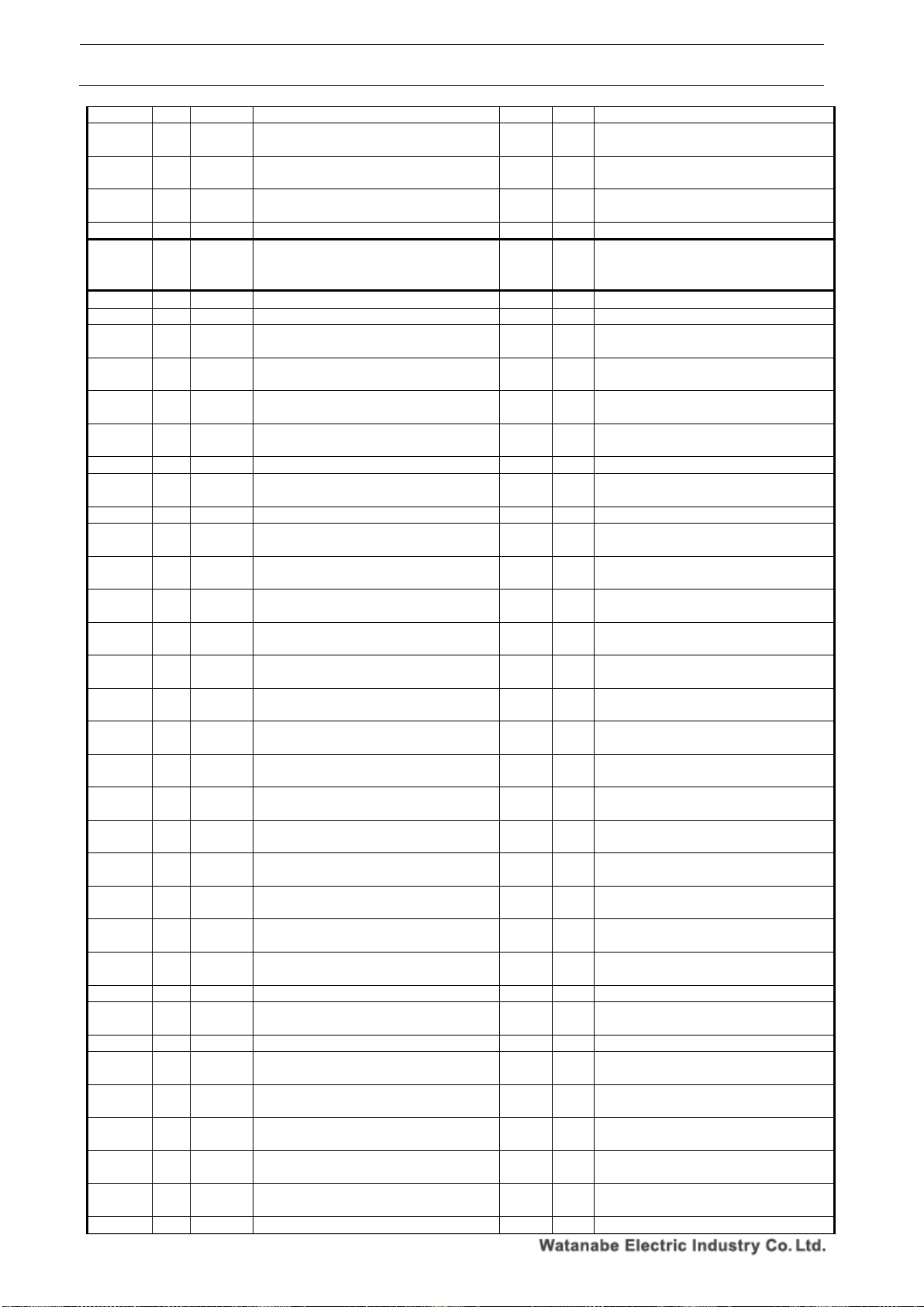
WPMZ Series Modbus communication instruction manual
IM-0862-02
Number of pages:109
43
unit 3rd character
0E9EH B 7
Pulse input, totalized value display Custom
unit 4th character
2
R/W
※Refer to “Pattern 1”
0E9FH B 7
Pulse input, totalized value display Custom
unit 5th character
2
R/W
※Refer to “Pattern 1”
0EA0H B 7
Pulse input, totalized value display Custom
unit 6th character
2
R/W
※Refer to “Pattern 1”
0EA1H B 7
Pulse input, totalized value overrun count
2
R/W
※Refer to “Pattern 1”
0EA2H
~
0EAFH
~ ~ Reserve
~ ~
0EB0H B 8
Pulse Input, input type
2
R/W
※Refer to “Pattern 1”
0EB1H B 8
Pulse input, input filter
2
R/W
※Refer to “Pattern 1”
0EB2H B 8
Sensor power supply for general purpose
pulse input type
2
R/W
※Refer to “Pattern 1”
0EB3H B 8
Sensor power supply for line driver input
type
2
R/W
※Refer to “Pattern 1”
0EB4H B 8
Pulse input, mantissa part of instantaneous
value display coefficient
4
R/W
※Refer to “Pattern 1”
0EB6H B 8
Pulse input, exponent part of instantaneous
value display coefficient
2
R/W
※Refer to “Pattern 1”
0EB7H B 8
Pulse input, instantaneous unit time.
2
R/W
※Refer to “Pattern 1”
0EB8H B 8
Pulse input, instantaneous value Decimal
point position
2
R/W
※Refer to “Pattern 1”
0EB9H B 8
Pulse input, instantaneous value display unit
2
R/W
※Refer to “Pattern 1”
0EBAH B 8
Pulse input, instantaneous value display
Custom unit 1st character
2
R/W
※Refer to “Pattern 1”
0EBBH B 8
Pulse input, instantaneous value display
Custom unit 2nd character
2
R/W
※Refer to “Pattern 1”
0EBCH B 8
Pulse input, instantaneous value display
Custom unit 3rd character
2
R/W
※Refer to “Pattern 1”
0EBDH B 8
Pulse input, instantaneous value display
Custom unit 4th character
2
R/W
※Refer to “Pattern 1”
0EBEH B 8
Pulse input, instantaneous value display
Custom unit 5th character
2
R/W
※Refer to “Pattern 1”
0EBFH B 8
Pulse input, instantaneous value display
Custom unit 6th character
2
R/W
※Refer to “Pattern 1”
0EC0H B 8
Pulse input, instantaneous value auto zero
time
2
R/W
※Refer to “Pattern 1”
0EC1H B 8
Pulse input, instantaneous value moving
average
2
R/W
※Refer to “Pattern 1”
0EC2H B 8
Pulse input, instantaneous value simple
average
2
R/W
※Refer to “Pattern 1”
0EC3H B 8
Pulse input, instantaneous value display
step
2
R/W
※Refer to “Pattern 1”
0EC4H B 8
Pulse input, mantissa part of totalized value
display coefficient
4
R/W
※Refer to “Pattern 1”
0EC6H B 8
Pulse input, mantissa part of totalized value
display value coefficient
2
R/W
※Refer to “Pattern 1”
0EC7H B 8
Pulse input, mantissa part of totalized value
default value
4
R/W
※Refer to “Pattern 1”
0EC9H B 8
Pulse input, exponent part of totalized value
default value
2
R/W
※Refer to “Pattern 1”
0ECAH B 8
Pulse input, total calculation direction
2
R/W
※Refer to “Pattern 1”
0ECBH B 8
Pulse input, totalized value Decimal point
position
2
R/W
※Refer to “Pattern 1”
0ECCH B 8
Pulse input, totalized value display unit
2
R/W
※Refer to “Pattern 1”
0ECDH B 8
Pulse input, totalized value display Custom
unit 1st character
2
R/W
※Refer to “Pattern 1”
0ECEH B 8
Pulse input, totalized value display Custom
unit 2nd character
2
R/W
※Refer to “Pattern 1”
0ECFH B 8
Pulse input, totalized value display Custom
unit 3rd character
2
R/W
※Refer to “Pattern 1”
0ED0H B 8
Pulse input, totalized value display Custom
unit 4th character
2
R/W
※Refer to “Pattern 1”
0ED1H B 8
Pulse input, totalized value display Custom
unit 5th character
2
R/W
※Refer to “Pattern 1”
0ED2H B 8
Pulse input, totalized value display Custom
2
R/W
※Refer to “Pattern 1”
Page 45
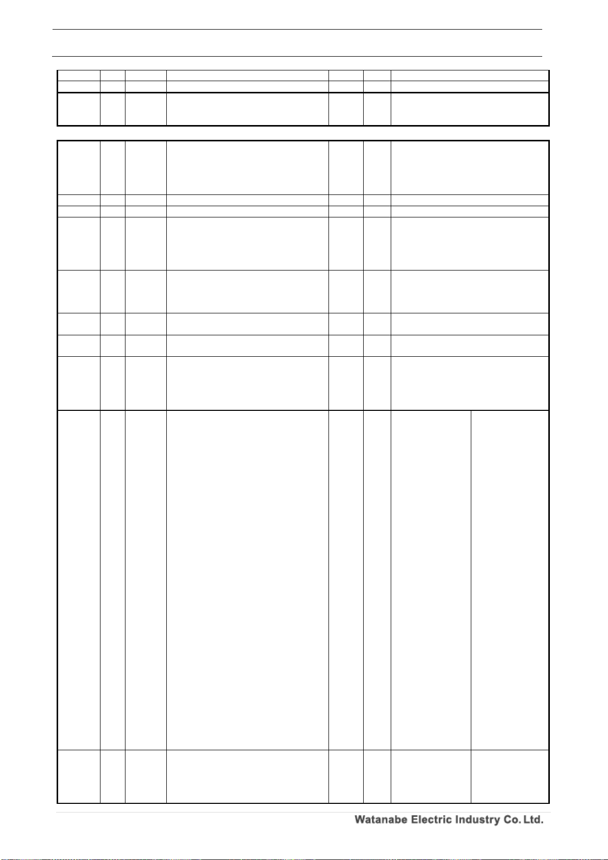
WPMZ Series Modbus communication instruction manual
IM-0862-02
Number of pages:109
44
unit 6th character
0ED3H B 8
Pulse input, totalized value overrun count
2
R/W
※Refer to “Pattern 1”
0ED4H
~
0EE1H
~ ~ Reserve
~ ~
-
0EE2H A 1
Analog input, input range
2
R/W
0000H:0~5V、
0001H:1~5V、
0002H:0~10V、
0003H:0~20mA、
0004H:4~20mA
0EE3H A 1
Analog input, sensor power supply
2
R/W
0000H:12V、0001H:24V
0EE4H A 1
Analog input, Low cut% value
4
R/W
0~99,999 [x0.001%]
0EE6 A 1
Analog input, simple average
2
R/W
0000H: None, 0001H: 2 times,
0002H: 4 times, 0003H: 8 times,
0004H: 16 times, 0005H: 32 times,
0006H: 64 times, 0007H: 128 times,
0008H: 256 times
0EE7H A 1
Analog input, moving average
2
R/W
0000H: None, 0001H: 2 times,
0002H: 4 times, 0003H: 8 times,
0004H: 16 times, 0005H: 32 times,
0006H: 64 times
0EE8H A 1
Analog input, mantissa part of
instantaneous value display coefficient
4
R/W
0~999,999
0EEAH A 1
Analog input, exponent part of
instantaneous value indication coefficient
2
R/W
-5~5
0EEBH A 1
Analog input, Instantaneous value Decimal
point position
2
R/W
0000H:None,
0001H:The lower right of the 2nd digit,
0002H:The lower right of the 3rd digit,
0003H:The lower right of the 4th digit,
0004H:The lower right of the 5th digit
0EECH A 1
Analog input, instantaneous value display
unit
2
R/W
0000H:None、
0002H:mA、
0004H:kA、
0006H:mV、
0008H:kV、
000AH:W、
000CH:MW、
000EH:mm、
0010H:m、
0012H:kΩ、
0014H:g、
0016H:N、
0018H:MN、
001AH:kPa、
001CH:hPa、
001EH:kJ、
0020H:Hz、
0022H:MHz、
0024H:mm/s、
0026H:cm/min、
0028H:m/min、
002AH:m/s2、
002CH:m3/min、
002EH:kg/h、
0030H:kg/m3、
0032H:ℓ、
0034H:ℓ/min、
0036H:%、
0038H:%RH、
003AH:ph、
003CH:rpm、
003EH:inch、
0001H:µA、
0003H:A、
0005H:µV、
0007H:V、
0009H:VA、
000BH:kW、
000DH:µm、
000FH:cm、
0011H:Ω、
0013H:MΩ、
0015H:kg、
0017H:kN、
0019H:Pa、
001BH:Mpa、
001DH:J、
001FH:MJ、
0021H:kHz、
0023H:m3、
0025H:mm/min、
0027H:m/s、
0029H:m/h
002BH:m3/s、
002DH:m3/h、
002FH:kg/m2、
0031H:N/m2、
0033H:ℓ/s、
0035H:ℓ/h、
0037H:‰、
0039H:℃、
003BH:ppm、
003DH:t、
003FH:Custom unit
0EEDH A 1
Analog input, instantaneous value display
Custom unit 1st character
2
R/W
0000H:None、
0002H:b、
0004H:d、
0006H:f、
0008H:h、
0001H:a、
0003H:c、
0005H:e、
0007H:g、
0009H:i、
Page 46
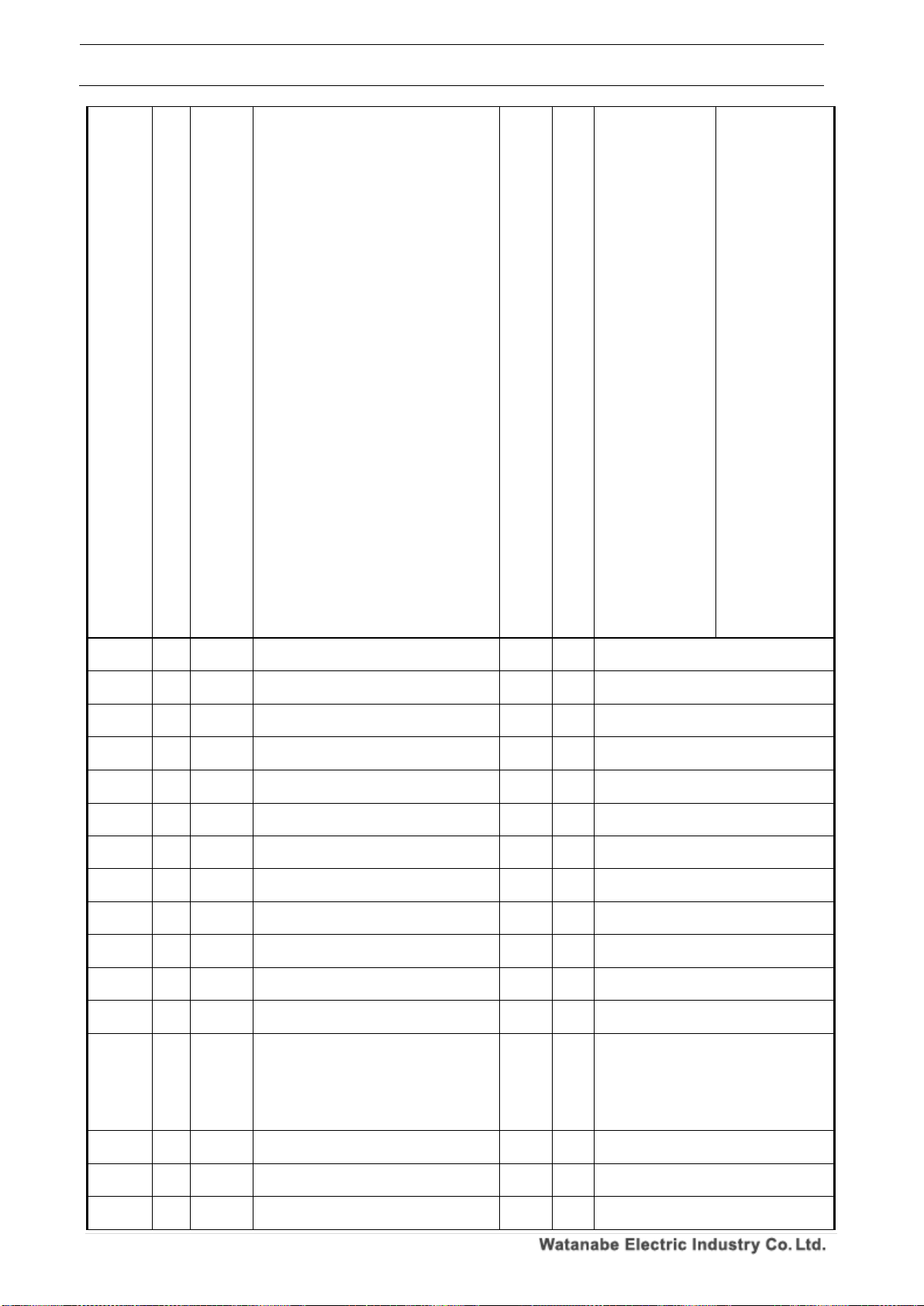
WPMZ Series Modbus communication instruction manual
IM-0862-02
Number of pages:109
45
000AH:j、
000CH:l、
000EH:n、
0010H:p、
0012H:r、
0014H:t、
0016H:v、
0018H:x、
001AH:z、
001CH:B、
001EH:D、
0020H:F、
0022H:H、
0024H:J、
0026H:L、
0028H:N、
002AH:P、
002CH:R、
002EH:T、
0030H:V、
0032H:X、
0034H:Z、
0036H:]、
0038H:)、
003AH:2、
003CH:1、
003EH:3、
0040H:µ、
0042H:g、
0044H:/、
0046H:%、
0048H:°、
004AH:”
000BH:k、
000DH:m、
000FH:o、
0011H:q、
0013H:s、
0015H:u、
0017H:w、
0019H:y、
001BH:A、
001DH:C、
001FH:E、
0021H:G、
0023H:I、
0025H:K、
0027H:M、
0029H:O
002BH:Q、
002DH:S、
002FH:U、
0031H:W、
0033H:Y、
0035H:[、
0037H:(、
0039H:1、
003BH:3、
003DH:2、
003FH:-、
0041H:Ω、
0043H:・、
0045H:ℓ、
0047H:‰、
0049H:’、
0EEEH A 1
Analog input, instantaneous value display
Custom unit 2nd character
2
R/W
※Refer to “Analog input, instantaneous
value display Custom unit 1st character”
0EEFH A 1
Analog input, instantaneous value display
Custom unit 3rd character
2
R/W
※Refer to “Analog input, instantaneous
value display Custom unit 1st character”
0EF0H A 1
Analog input, instantaneous value display
Custom unit 4th character
2
R/W
※Refer to “Analog input, instantaneous
value display Custom unit 1st character”
0EF1H A 1
Analog input, instantaneous value display
Custom unit 5th character
2
R/W
※Refer to “Analog input, instantaneous
value display Custom unit 1st character”
0EF2H A 1
Analog input, instantaneous value display
Custom unit 6th character
2
R/W
※Refer to “Analog input, instantaneous
value display Custom unit 1st character”
0EF3H A 1
Analog input, instantaneous value display
step
2
R/W
0000H:None、0001H:5 steps、
0002H:10 steps
0EF4H A 1
Analog input, mantissa part of totalized
value display coefficient
4
R/W
0~999,999
0EF6H A 1
Analog input, exponent part of totalized
value display coefficient
2
R/W
-9~9
0EF7H A 1
Analog input, time unit of totalized unit time.
2
R/W
0000 H: Second, 0001 H: Minute,
0002 H: Hour
0EF8H A 1
Analog input, mantissa part of integration
initial value
4
R/W
-999,999~999,999
0EFAH A 1
Analog input, exponent part of integration
initial value
2
R/W
-9~9
0EFBH A 1
Analog input, total calculation direction
2
R/W
0000H: AddToDefault,
0001H: SubFromDefault
0EFCH A 1
Analog input, totalized value Decimal point
position
2
R/W
0000H:None,
0001H:The lower right of the 2nd digit,
0002H:The lower right of the 3rd digit,
0003H:The lower right of the 4th digit,
0004H:The lower right of the 5th digit,
0005H:The lower right of the 6th digit
0EFDH A 1
Analog input, totalized value display unit
2
R/W
※Refer to “Analog input, instantaneous
value display unit”
0EFEH A 1
Analog input, totalized value display Custom
unit 1st character
2
R/W
※Refer to “Analog input, instantaneous
value display Custom unit 1st character”
0EFFH A 1
Analog input, totalized value display Custom
unit 2nd character
2
R/W
※Refer to “Analog input, instantaneous
value display Custom unit 1st character”
Page 47
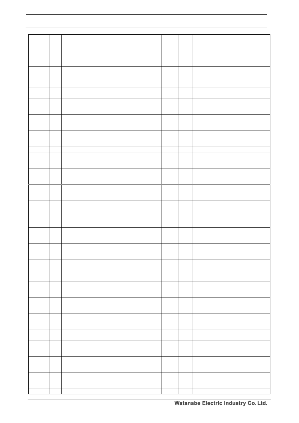
WPMZ Series Modbus communication instruction manual
IM-0862-02
Number of pages:109
46
0F00H A 1
Analog input, totalized value display Custom
unit 3rd character
2
R/W
※Refer to “Analog input, instantaneous
value display Custom unit 1st character”
0F01H A 1
Analog input, totalized value display Custom
unit 4th character
2
R/W
※Refer to “Analog input, instantaneous
value display Custom unit 1st character”
0F02H A 1
Analog input, totalized value display Custom
unit 5th character
2
R/W
※Refer to “Analog input, instantaneous
value display Custom unit 1st character”
0F03H A 1
Analog input, totalized value display Custom
unit 6th character
2
R/W
※Refer to “Analog input, instantaneous
value display Custom unit 1st character”
0F04H A 1
Analog input, totalized over operation
2
R/W
0000H:None、0001H:999 times、
0002H:Endless
0F05H A 1
Analog input, linearize function
2
R/W
0000H:None、0001H:Linearize、
0002H:Square root
0F06H A 1
Analog input, linearize 1st point input value
4
R/W
0~100,000 [x0.001%]
0F08H A 1
Analog input, linearize 1st point output
value
4
R/W
0~100,000 [x0.001%]
0F0AH A 1
Analog input, linearize 2nd point input value
4
R/W
0~100,000 [x0.001%]
0F0CH A 1
Analog input, linearize 2nd point output
value
4
R/W
0~100,000 [x0.001%]
0F0EH A 1
Analog input, linearize 3rd point input value
4
R/W
0~100,000 [x0.001%]
0F10H A 1
Analog input, linearize 3rd point output
value
4
R/W
0~100,000 [x0.001%]
0F12H A 1
Analog input, linearize 4th point input value
4
R/W
0~100,000 [x0.001%]
0F14H A 1
Analog input, linearize 4th point output
value
4
R/W
0~100,000 [x0.001%]
0F16H A 1
Analog input, linearize 5th point input value
4
R/W
0~100,000 [x0.001%]
0F18H A 1
Analog input, linearize 5th point output
value
4
R/W
0~100,000 [x0.001%]
0F1AH A 1
Analog input, linearize 6th point input value
4
R/W
0~100,000 [x0.001%]
0F1CH A 1
Analog input, linearize 6th point output
value
4
R/W
0~100,000 [x0.001%]
0F1EH A 1
Analog input, linearize 7th point input value
4
R/W
0~100,000 [x0.001%]
0F20H A 1
Analog input, linearize 7th point output
value
4
R/W
0~100,000 [x0.001%]
0F22H A 1
Analog input, linearize 8th point input value
4
R/W
0~100,000 [x0.001%]
0F24H A 1
Analog input, linearize 8th point output
value
4
R/W
0~100,000 [x0.001%]
0F26H A 1
Analog input, linearize 9th point input value
4
R/W
0~100,000 [x0.001%]
0F28H A 1
Analog input, linearize 9th point output
value
4
R/W
0~100,000 [x0.001%]
0F2AH A 1
Analog input, linearize 10th point input value
4
R/W
0~100,000 [x0.001%]
0F2CH A 1
Analog input, linearize 10th point output
value
4
R/W
0~100,000 [x0.001%]
0F2EH A 1
Analog input, linearize 11th point input value
4
R/W
0~100,000 [x0.001%]
0F30H A 1
Analog input, linearize 11th point output
value
4
R/W
0~100,000 [x0.001%]
0F32H A 1
Analog input, linearize 12th point input value
4
R/W
0~100,000 [x0.001%]
0F34H A 1
Analog input, linearize 12th point output
value
4
R/W
0~100,000 [x0.001%]
0F36H A 1
Analog input, linearize 13th point input value
4
R/W
0~100,000 [x0.001%]
0F38H A 1
Analog input, linearize 13th point output
value
4
R/W
0~100,000 [x0.001%]
0F3AH A 1
Analog input, linearize 14th point input value
4
R/W
0~100,000 [x0.001%]
0F3CH A 1
Analog input, linearize 14th point output
value
4
R/W
0~100,000 [x0.001%]
0F3EH A 1
Analog input, linearize 15th point input value
4
R/W
0~100,000 [x0.001%]
0F40H A 1
Analog input, linearize 15th point output
value
4
R/W
0~100,000 [x0.001%]
0F42H A 1
Analog input, linearize 16th point input value
4
R/W
0~100,000 [x0.001%]
0F44H A 1
Analog input, linearize 16th point output
value
4
R/W
0~100,000 [x0.001%]
0F46H A 1
Analog input, linearize 17th point input value
4
R/W
0~100,000 [x0.001%]
0F48H A 1
Analog input, linearize 17th point output
value
4
R/W
0~100,000 [x0.001%]
0F4AH A 1
Analog input, linearize 18th point input value
4
R/W
0~100,000 [x0.001%]
0F4CH A 1
Analog input, linearize 18th point output
value
4
R/W
0~100,000 [x0.001%]
0F4EH A 1
Analog input, linearize 19th point input value
4
R/W
0~100,000 [x0.001%]
Page 48
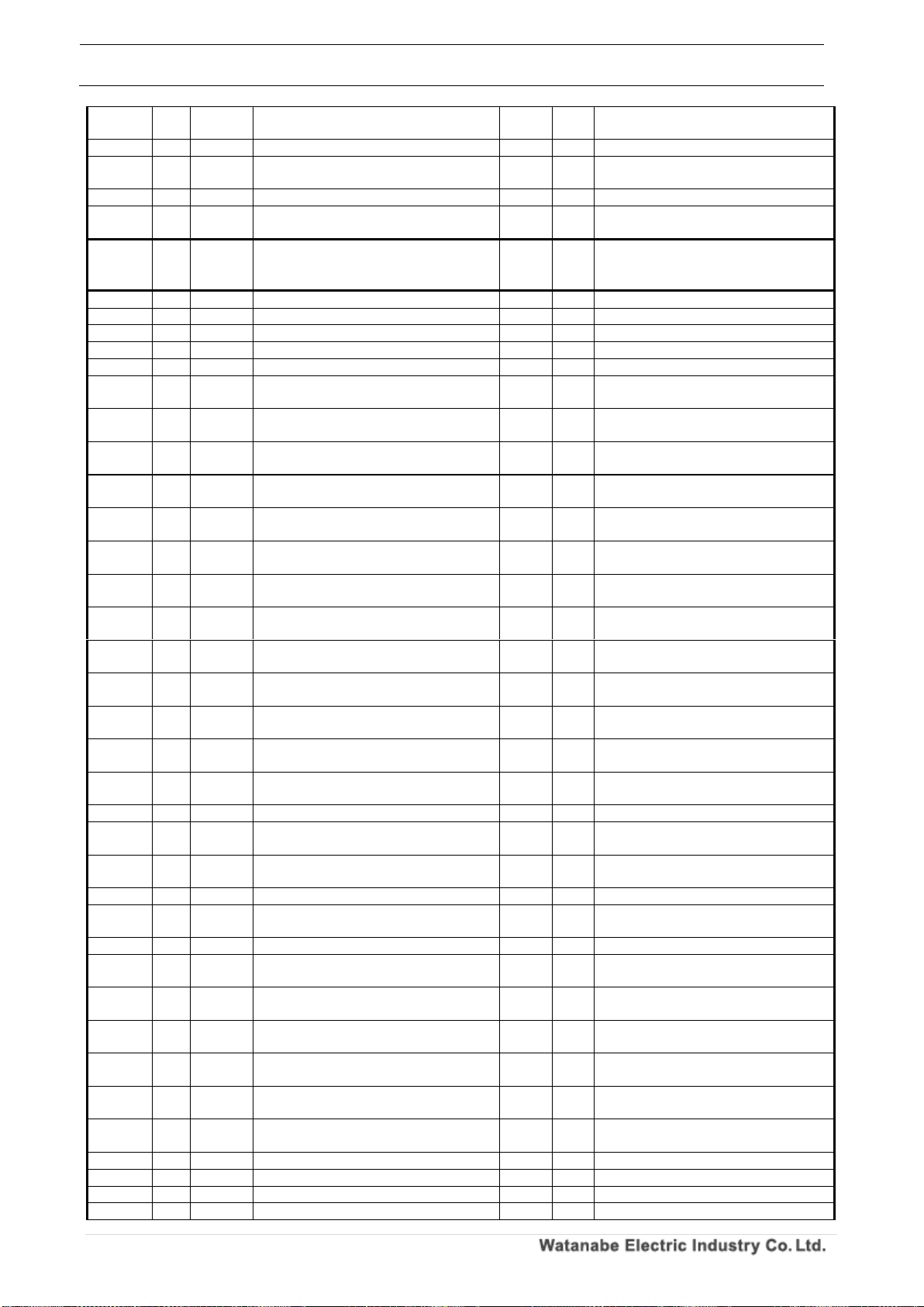
WPMZ Series Modbus communication instruction manual
IM-0862-02
Number of pages:109
47
0F50H A 1
Analog input, linearize 19th point output
value
4
R/W
0~100,000 [x0.001%]
0F52H A 1
Analog input, linearize 20th point input value
4
R/W
0~100,000 [x0.001%]
0F54H A 1
Analog input, linearize 20th point output
value
4
R/W
0~100,000 [x0.001%]
0F56H A 1
Analog input, linearize 21st point input value
4
R/W
0~100,000 [x0.001%]
0F58H A 1
Analog input, linearize 21st point output
value
4
R/W
0~100,000 [x0.001%]
0F5AH
~
0F63H
~ ~ Reserve
~ ~
F64 H A 2
Analog input, input range
2
R/W
※Refer to “Pattern 1”
F65 H A 2
Analog input, sensor power supply
2
R/W
※Refer to “Pattern 1”
F66 H A 2
Analog input, Low cut% value
4
R/W
※Refer to “Pattern 1”
F68 H A 2
Analog input, simple average
2
R/W
※Refer to “Pattern 1”
F69 H A 2
Analog input, moving average
2
R/W
※Refer to “Pattern 1”
F6A H A 2
Analog input, mantissa part of
instantaneous value display coefficient
4
R/W
※Refer to “Pattern 1”
F6C H A 2
Analog input, exponent part of
instantaneous value indication coefficient
2
R/W
※Refer to “Pattern 1”
F6D H A 2
Analog input, Instantaneous value Decimal
point position
2
R/W
※Refer to “Pattern 1”
F6E H A 2
Analog input, instantaneous value display
unit
2
R/W
※Refer to “Pattern 1”
F6F H A 2
Analog input, instantaneous value display
Custom unit 1st character
2
R/W
※Refer to “Pattern 1”
F70 H A 2
Analog input, instantaneous value display
Custom unit 2nd character
2
R/W
※Refer to “Pattern 1”
F71 H A 2
Analog input, instantaneous value display
Custom unit 3rd character
2
R/W
※Refer to “Pattern 1”
F72 H A 2
Analog input, instantaneous value display
Custom unit 4th character
2
R/W
※Refer to “Pattern 1”
F73 H A 2
Analog input, instantaneous value display
Custom unit 5th character
2
R/W
※Refer to “Pattern 1”
F74 H A 2
Analog input, instantaneous value display
Custom unit 6th character
2
R/W
※Refer to “Pattern 1”
F75 H A 2
Analog input, instantaneous value display
step
2
R/W
※Refer to “Pattern 1”
F76 H A 2
Analog input, mantissa part of totalized
value display coefficient
4
R/W
※Refer to “Pattern 1”
F78 H A 2
Analog input, exponent part of totalized
value display coefficient
2
R/W
※Refer to “Pattern 1”
F79 H A 2
Analog input, time unit of totalized unit time.
2
R/W
※Refer to “Pattern 1”
F7A H A 2
Analog input, mantissa part of integration
initial value
4
R/W
※Refer to “Pattern 1”
F7C H A 2
Analog input, exponent part of integration
initial value
2
R/W
※Refer to “Pattern 1”
F7D H A 2
Analog input, total calculation direction
2
R/W
※Refer to “Pattern 1”
F7E H A 2
Analog input, totalized value Decimal point
position
2
R/W
※Refer to “Pattern 1”
F7F H A 2
Analog input, totalized value display unit
2
R/W
※Refer to “Pattern 1”
F80 H A 2
Analog input, totalized value display Custom
unit 1st character
2
R/W
※Refer to “Pattern 1”
F81 H A 2
Analog input, totalized value display Custom
unit 2nd character
2
R/W
※Refer to “Pattern 1”
F82 H A 2
Analog input, totalized value display Custom
unit 3rd character
2
R/W
※Refer to “Pattern 1”
F83 H A 2
Analog input, totalized value display Custom
unit 4th character
2
R/W
※Refer to “Pattern 1”
F84 H A 2
Analog input, totalized value display Custom
unit 5th character
2
R/W
※Refer to “Pattern 1”
F85 H A 2
Analog input, totalized value display Custom
unit 6th character
2
R/W
※Refer to “Pattern 1”
F86 H A 2
Analog input, totalized over operation
2
R/W
※Refer to “Pattern 1”
F87 H A 2
Analog input, linearize function
2
R/W
※Refer to “Pattern 1”
F88 H A 2
Analog input, linearize 1st point input value
4
R/W
※Refer to “Pattern 1”
F8A H A 2
Analog input, linearize 1st point output
4
R/W
※Refer to “Pattern 1”
Page 49
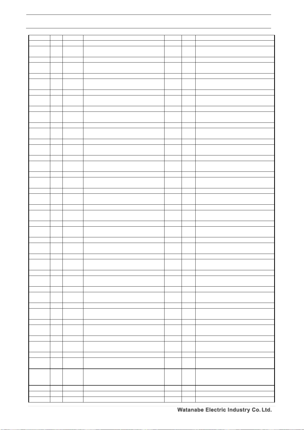
WPMZ Series Modbus communication instruction manual
IM-0862-02
Number of pages:109
48
value
F8C H A 2
Analog input, linearize 2nd point input value
4
R/W
※Refer to “Pattern 1”
F8E H A 2
Analog input, linearize 2nd point output
value
4
R/W
※Refer to “Pattern 1”
F90 H A 2
Analog input, linearize 3rd point input value
4
R/W
※Refer to “Pattern 1”
F92 H A 2
Analog input, linearize 3rd point output
value
4
R/W
※Refer to “Pattern 1”
F94 H A 2
Analog input, linearize 4th point input value
4
R/W
※Refer to “Pattern 1”
F96 H A 2
Analog input, linearize 4th point output
value
4
R/W
※Refer to “Pattern 1”
F98 H A 2
Analog input, linearize 5th point input value
4
R/W
※Refer to “Pattern 1”
F9A H A 2
Analog input, linearize 5th point output
value
4
R/W
※Refer to “Pattern 1”
F9C H A 2
Analog input, linearize 6th point input value
4
R/W
※Refer to “Pattern 1”
F9E H A 2
Analog input, linearize 6th point output
value
4
R/W
※Refer to “Pattern 1”
FA0 H A 2
Analog input, linearize 7th point input value
4
R/W
※Refer to “Pattern 1”
FA2 H A 2
Analog input, linearize 7th point output
value
4
R/W
※Refer to “Pattern 1”
FA4 H A 2
Analog input, linearize 8th point input value
4
R/W
※Refer to “Pattern 1”
FA6 H A 2
Analog input, linearize 8th point output
value
4
R/W
※Refer to “Pattern 1”
FA8 H A 2
Analog input, linearize 9th point input value
4
R/W
※Refer to “Pattern 1”
FAA H A 2
Analog input, linearize 9th point output
value
4
R/W
※Refer to “Pattern 1”
FAC H A 2
Analog input, linearize 10th point input value
4
R/W
※Refer to “Pattern 1”
FAE H A 2
Analog input, linearize 10th point output
value
4
R/W
※Refer to “Pattern 1”
FB0 H A 2
Analog input, linearize 11th point input value
4
R/W
※Refer to “Pattern 1”
FB2 H A 2
Analog input, linearize 11th point output
value
4
R/W
※Refer to “Pattern 1”
FB4 H A 2
Analog input, linearize 12th point input value
4
R/W
※Refer to “Pattern 1”
FB6 H A 2
Analog input, linearize 12th point output
value
4
R/W
※Refer to “Pattern 1”
FB8 H A 2
Analog input, linearize 13th point input value
4
R/W
※Refer to “Pattern 1”
FBA H A 2
Analog input, linearize 13th point output
value
4
R/W
※Refer to “Pattern 1”
FBC H A 2
Analog input, linearize 14th point input value
4
R/W
※Refer to “Pattern 1”
FBE H A 2
Analog input, linearize 14th point output
value
4
R/W
※Refer to “Pattern 1”
FC0 H A 2
Analog input, linearize 15th point input value
4
R/W
※Refer to “Pattern 1”
FC2 H A 2
Analog input, linearize 15th point output
value
4
R/W
※Refer to “Pattern 1”
FC4 H A 2
Analog input, linearize 16th point input value
4
R/W
※Refer to “Pattern 1”
FC6 H A 2
Analog input, linearize 16th point output
value
4
R/W
※Refer to “Pattern 1”
FC8 H A 2
Analog input, linearize 17th point input value
4
R/W
※Refer to “Pattern 1”
FCA H A 2
Analog input, linearize 17th point output
value
4
R/W
※Refer to “Pattern 1”
FCC H A 2
Analog input, linearize 18th point input value
4
R/W
※Refer to “Pattern 1”
FCE H A 2
Analog input, linearize 18th point output
value
4
R/W
※Refer to “Pattern 1”
FD0 H A 2
Analog input, linearize 19th point input value
4
R/W
※Refer to “Pattern 1”
FD2 H A 2
Analog input, linearize 19th point output
value
4
R/W
※Refer to “Pattern 1”
FD4 H A 2
Analog input, linearize 20th point input value
4
R/W
※Refer to “Pattern 1”
FD6 H A 2
Analog input, linearize 20th point output
value
4
R/W
※Refer to “Pattern 1”
FD8 H A 2
Analog input, linearize 21st point input value
4
R/W
※Refer to “Pattern 1”
FDA H A 2
Analog input, linearize 21st point output
value
4
R/W
※Refer to “Pattern 1”
FDC H
~
0FE5H
~ ~ Reserve
~ ~
FE6 H A 3
Analog input, input range
2
R/W
※Refer to “Pattern 1”
FE7 H A 3
Analog input, sensor power supply
2
R/W
※Refer to “Pattern 1”
FE8 H A 3
Analog input, Low cut% value
4
R/W
※Refer to “Pattern 1”
Page 50
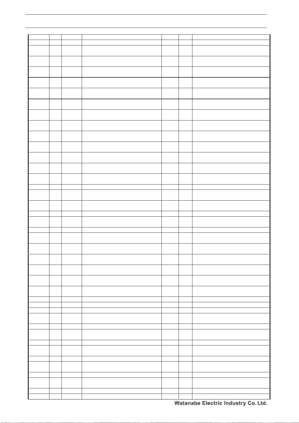
WPMZ Series Modbus communication instruction manual
IM-0862-02
Number of pages:109
49
FEA H A 3
Analog input, simple average
2
R/W
※Refer to “Pattern 1”
FEB H A 3
Analog input, moving average
2
R/W
※Refer to “Pattern 1”
FEC H A 3
Analog input, mantissa part of
instantaneous value display coefficient
4
R/W
※Refer to “Pattern 1”
FEE H A 3
Analog input, exponent part of
instantaneous value indication coefficient
2
R/W
※Refer to “Pattern 1”
FEF H A 3
Analog input, Instantaneous value Decimal
point position
2
R/W
※Refer to “Pattern 1”
FF0 H A 3
Analog input, instantaneous value display
unit
2
R/W
※Refer to “Pattern 1”
FF1 H A 3
Analog input, instantaneous value display
Custom unit 1st character
2
R/W
※Refer to “Pattern 1”
FF2 H A 3
Analog input, instantaneous value display
Custom unit 2nd character
2
R/W
※Refer to “Pattern 1”
FF3 H A 3
Analog input, instantaneous value display
Custom unit 3rd character
2
R/W
※Refer to “Pattern 1”
FF4 H A 3
Analog input, instantaneous value display
Custom unit 4th character
2
R/W
※Refer to “Pattern 1”
FF5 H A 3
Analog input, instantaneous value display
Custom unit 5th character
2
R/W
※Refer to “Pattern 1”
FF6 H A 3
Analog input, instantaneous value display
Custom unit 6th character
2
R/W
※Refer to “Pattern 1”
FF7 H A 3
Analog input, instantaneous value display
step
2
R/W
※Refer to “Pattern 1”
FF8 H A 3
Analog input, mantissa part of totalized
value display coefficient
4
R/W
※Refer to “Pattern 1”
FFA H A 3
Analog input, exponent part of totalized
value display coefficient
2
R/W
※Refer to “Pattern 1”
FFB H A 3
Analog input, time unit of totalized unit time.
2
R/W
※Refer to “Pattern 1”
FFC H A 3
Analog input, mantissa part of integration
initial value
4
R/W
※Refer to “Pattern 1”
FFE H A 3
Analog input, exponent part of integration
initial value
2
R/W
※Refer to “Pattern 1”
FFF H A 3
Analog input, total calculation direction
2
R/W
※Refer to “Pattern 1”
1000 H A 3
Analog input, totalized value Decimal point
position
2
R/W
※Refer to “Pattern 1”
1001 H A 3
Analog input, totalized value display unit
2
R/W
※Refer to “Pattern 1”
1002 H A 3
Analog input, totalized value display Custom
unit 1st character
2
R/W
※Refer to “Pattern 1”
1003 H A 3
Analog input, totalized value display Custom
unit 2nd character
2
R/W
※Refer to “Pattern 1”
1004 H A 3
Analog input, totalized value display Custom
unit 3rd character
2
R/W
※Refer to “Pattern 1”
1005 H A 3
Analog input, totalized value display Custom
unit 4th character
2
R/W
※Refer to “Pattern 1”
1006 H A 3
Analog input, totalized value display Custom
unit 5th character
2
R/W
※Refer to “Pattern 1”
1007 H A 3
Analog input, totalized value display Custom
unit 6th character
2
R/W
※Refer to “Pattern 1”
1008 H A 3
Analog input, totalized over operation
2
R/W
※Refer to “Pattern 1”
1009 H A 3
Analog input, linearize function
2
R/W
※Refer to “Pattern 1”
100A H A 3
Analog input, linearize 1st point input value
4
R/W
※Refer to “Pattern 1”
100C H A 3
Analog input, linearize 1st point output
value
4
R/W
※Refer to “Pattern 1”
100E H A 3
Analog input, linearize 2nd point input value
4
R/W
※Refer to “Pattern 1”
1010 H A 3
Analog input, linearize 2nd point output
value
4
R/W
※Refer to “Pattern 1”
1012 H A 3
Analog input, linearize 3rd point input value
4
R/W
※Refer to “Pattern 1”
1014 H A 3
Analog input, linearize 3rd point output
value
4
R/W
※Refer to “Pattern 1”
1016 H A 3
Analog input, linearize 4th point input value
4
R/W
※Refer to “Pattern 1”
1018 H A 3
Analog input, linearize 4th point output
value
4
R/W
※Refer to “Pattern 1”
101A H A 3
Analog input, linearize 5th point input value
4
R/W
※Refer to “Pattern 1”
101C H A 3
Analog input, linearize 5th point output
value
4
R/W
※Refer to “Pattern 1”
101E H A 3
Analog input, linearize 6th point input value
4
R/W
※Refer to “Pattern 1”
1020 H A 3
Analog input, linearize 6th point output
4
R/W
※Refer to “Pattern 1”
Page 51
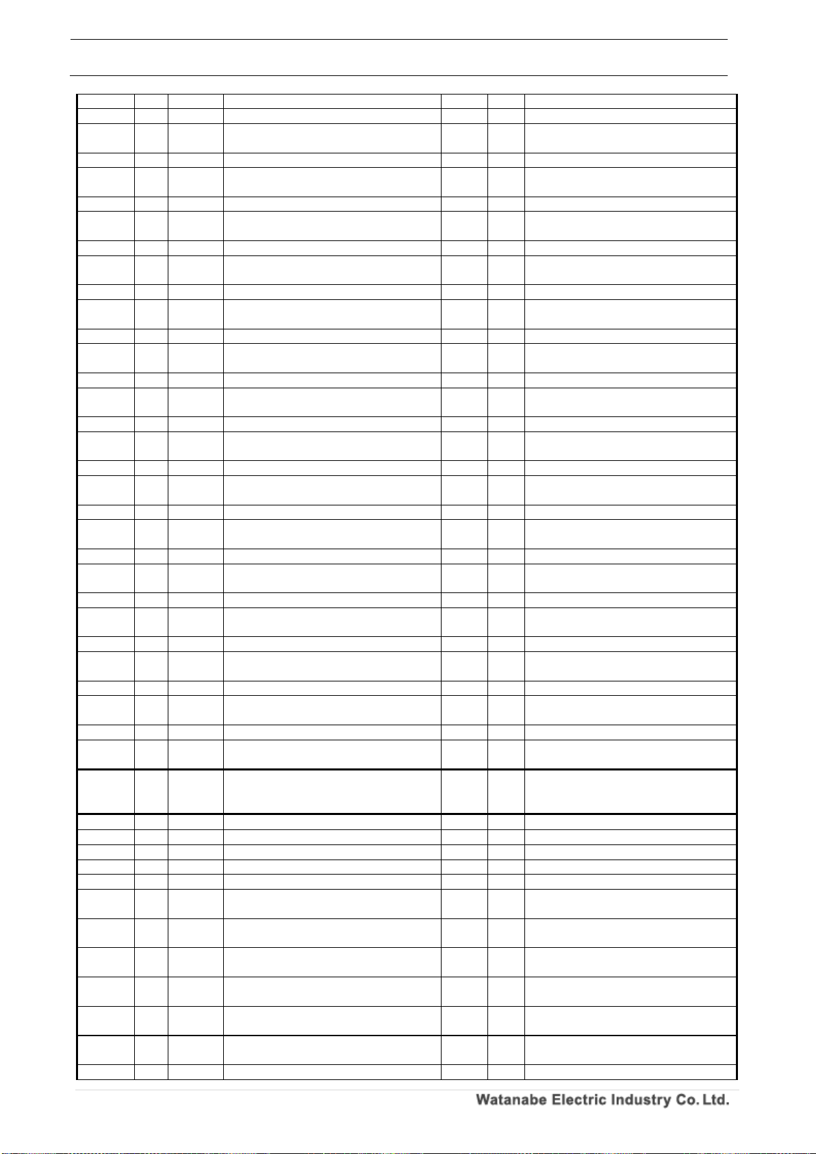
WPMZ Series Modbus communication instruction manual
IM-0862-02
Number of pages:109
50
value
1022 H A 3
Analog input, linearize 7th point input value
4
R/W
※Refer to “Pattern 1”
1024 H A 3
Analog input, linearize 7th point output
value
4
R/W
※Refer to “Pattern 1”
1026 H A 3
Analog input, linearize 8th point input value
4
R/W
※Refer to “Pattern 1”
1028 H A 3
Analog input, linearize 8th point output
value
4
R/W
※Refer to “Pattern 1”
102A H A 3
Analog input, linearize 9th point input value
4
R/W
※Refer to “Pattern 1”
102C H A 3
Analog input, linearize 9th point output
value
4
R/W
※Refer to “Pattern 1”
102E H A 3
Analog input, linearize 10th point input value
4
R/W
※Refer to “Pattern 1”
1030 H A 3
Analog input, linearize 10th point output
value
4
R/W
※Refer to “Pattern 1”
1032 H A 3
Analog input, linearize 11th point input value
4
R/W
※Refer to “Pattern 1”
1034 H A 3
Analog input, linearize 11th point output
value
4
R/W
※Refer to “Pattern 1”
1036 H A 3
Analog input, linearize 12th point input value
4
R/W
※Refer to “Pattern 1”
1038 H A 3
Analog input, linearize 12th point output
value
4
R/W
※Refer to “Pattern 1”
103A H A 3
Analog input, linearize 13th point input value
4
R/W
※Refer to “Pattern 1”
103C H A 3
Analog input, linearize 13th point output
value
4
R/W
※Refer to “Pattern 1”
103E H A 3
Analog input, linearize 14th point input value
4
R/W
※Refer to “Pattern 1”
1040 H A 3
Analog input, linearize 14th point output
value
4
R/W
※Refer to “Pattern 1”
1042 H A 3
Analog input, linearize 15th point input value
4
R/W
※Refer to “Pattern 1”
1044 H A 3
Analog input, linearize 15th point output
value
4
R/W
※Refer to “Pattern 1”
1046 H A 3
Analog input, linearize 16th point input value
4
R/W
※Refer to “Pattern 1”
1048 H A 3
Analog input, linearize 16th point output
value
4
R/W
※Refer to “Pattern 1”
104A H A 3
Analog input, linearize 17th point input value
4
R/W
※Refer to “Pattern 1”
104C H A 3
Analog input, linearize 17th point output
value
4
R/W
※Refer to “Pattern 1”
104E H A 3
Analog input, linearize 18th point input value
4
R/W
※Refer to “Pattern 1”
1050 H A 3
Analog input, linearize 18th point output
value
4
R/W
※Refer to “Pattern 1”
1052 H A 3
Analog input, linearize 19th point input value
4
R/W
※Refer to “Pattern 1”
1054 H A 3
Analog input, linearize 19th point output
value
4
R/W
※Refer to “Pattern 1”
1056 H A 3
Analog input, linearize 20th point input value
4
R/W
※Refer to “Pattern 1”
1058 H A 3
Analog input, linearize 20th point output
value
4
R/W
※Refer to “Pattern 1”
105A H A 3
Analog input, linearize 21st point input value
4
R/W
※Refer to “Pattern 1”
105C H A 3
Analog input, linearize 21st point output
value
4
R/W
※Refer to “Pattern 1”
105E H
~
1067 H
~ ~ Reserve
~ ~
1068 H A 4
Analog input, input range
2
R/W
※Refer to “Pattern 1”
1069 H A 4
Analog input, sensor power supply
2
R/W
※Refer to “Pattern 1”
106A H A 4
Analog input, Low cut% value
4
R/W
※Refer to “Pattern 1”
106C H A 4
Analog input, simple average
2
R/W
※Refer to “Pattern 1”
106D H A 4
Analog input, moving average
2
R/W
※Refer to “Pattern 1”
106E H A 4
Analog input, mantissa part of
instantaneous value display coefficient
4
R/W
※Refer to “Pattern 1”
1070 H A 4
Analog input, exponent part of
instantaneous value indication coefficient
2
R/W
※Refer to “Pattern 1”
1071 H A 4
Analog input, Instantaneous value Decimal
point position
2
R/W
※Refer to “Pattern 1”
1072 H A 4
Analog input, instantaneous value display
unit
2
R/W
※Refer to “Pattern 1”
1073 H A 4
Analog input, instantaneous value display
Custom unit 1st character
2
R/W
※Refer to “Pattern 1”
1074 H A 4
Analog input, instantaneous value display
Custom unit 2nd character
2
R/W
※Refer to “Pattern 1”
1075 H A 4
Analog input, instantaneous value display
2
R/W
※Refer to “Pattern 1”
Page 52
WPMZ Series Modbus communication instruction manual
IM-0862-02
Number of pages:109
51
Custom unit 3rd character
1076 H A 4
Analog input, instantaneous value display
Custom unit 4th character
2
R/W
※Refer to “Pattern 1”
1077 H A 4
Analog input, instantaneous value display
Custom unit 5th character
2
R/W
※Refer to “Pattern 1”
1078 H A 4
Analog input, instantaneous value display
Custom unit 6th character
2
R/W
※Refer to “Pattern 1”
1079 H A 4
Analog input, instantaneous value display
step
2
R/W
※Refer to “Pattern 1”
107A H A 4
Analog input, mantissa part of totalized
value display coefficient
4
R/W
※Refer to “Pattern 1”
107C H A 4
Analog input, exponent part of totalized
value display coefficient
2
R/W
※Refer to “Pattern 1”
107D H A 4
Analog input, time unit of totalized unit time.
2
R/W
※Refer to “Pattern 1”
107E H A 4
Analog input, mantissa part of integration
initial value
4
R/W
※Refer to “Pattern 1”
1080 H A 4
Analog input, exponent part of integration
initial value
2
R/W
※Refer to “Pattern 1”
1081 H A 4
Analog input, total calculation direction
2
R/W
※Refer to “Pattern 1”
1082 H A 4
Analog input, totalized value Decimal point
position
2
R/W
※Refer to “Pattern 1”
1083 H A 4
Analog input, totalized value display unit
2
R/W
※Refer to “Pattern 1”
1084 H A 4
Analog input, totalized value display Custom
unit 1st character
2
R/W
※Refer to “Pattern 1”
1085 H A 4
Analog input, totalized value display Custom
unit 2nd character
2
R/W
※Refer to “Pattern 1”
1086 H A 4
Analog input, totalized value display Custom
unit 3rd character
2
R/W
※Refer to “Pattern 1”
1087 H A 4
Analog input, totalized value display Custom
unit 4th character
2
R/W
※Refer to “Pattern 1”
1088 H A 4
Analog input, totalized value display Custom
unit 5th character
2
R/W
※Refer to “Pattern 1”
1089 H A 4
Analog input, totalized value display Custom
unit 6th character
2
R/W
※Refer to “Pattern 1”
108A H A 4
Analog input, totalized over operation
2
R/W
※Refer to “Pattern 1”
108B H A 4
Analog input, linearize function
2
R/W
※Refer to “Pattern 1”
108C H A 4
Analog input, linearize 1st point input value
4
R/W
※Refer to “Pattern 1”
108E H A 4
Analog input, linearize 1st point output
value
4
R/W
※Refer to “Pattern 1”
1090 H A 4
Analog input, linearize 2nd point input value
4
R/W
※Refer to “Pattern 1”
1092 H A 4
Analog input, linearize 2nd point output
value
4
R/W
※Refer to “Pattern 1”
1094 H A 4
Analog input, linearize 3rd point input value
4
R/W
※Refer to “Pattern 1”
1096 H A 4
Analog input, linearize 3rd point output
value
4
R/W
※Refer to “Pattern 1”
1098 H A 4
Analog input, linearize 4th point input value
4
R/W
※Refer to “Pattern 1”
109A H A 4
Analog input, linearize 4th point output
value
4
R/W
※Refer to “Pattern 1”
109C H A 4
Analog input, linearize 5th point input value
4
R/W
※Refer to “Pattern 1”
109E H A 4
Analog input, linearize 5th point output
value
4
R/W
※Refer to “Pattern 1”
10A0 H A 4
Analog input, linearize 6th point input value
4
R/W
※Refer to “Pattern 1”
10A2 H A 4
Analog input, linearize 6th point output
value
4
R/W
※Refer to “Pattern 1”
10A4 H A 4
Analog input, linearize 7th point input value
4
R/W
※Refer to “Pattern 1”
10A6 H A 4
Analog input, linearize 7th point output
value
4
R/W
※Refer to “Pattern 1”
10A8 H A 4
Analog input, linearize 8th point input value
4
R/W
※Refer to “Pattern 1”
10AA H A 4
Analog input, linearize 8th point output
value
4
R/W
※Refer to “Pattern 1”
10AC H A 4
Analog input, linearize 9th point input value
4
R/W
※Refer to “Pattern 1”
10AE H A 4
Analog input, linearize 9th point output
value
4
R/W
※Refer to “Pattern 1”
10B0 H A 4
Analog input, linearize 10th point input value
4
R/W
※Refer to “Pattern 1”
10B2 H A 4
Analog input, linearize 10th point output
value
4
R/W
※Refer to “Pattern 1”
10B4 H A 4
Analog input, linearize 11th point input value
4
R/W
※Refer to “Pattern 1”
Page 53
WPMZ Series Modbus communication instruction manual
IM-0862-02
Number of pages:109
52
10B6 H A 4
Analog input, linearize 11th point output
value
4
R/W
※Refer to “Pattern 1”
10B8 H A 4
Analog input, linearize 12th point input value
4
R/W
※Refer to “Pattern 1”
10BA H A 4
Analog input, linearize 12th point output
value
4
R/W
※Refer to “Pattern 1”
10BC H A 4
Analog input, linearize 13th point input value
4
R/W
※Refer to “Pattern 1”
10BE H A 4
Analog input, linearize 13th point output
value
4
R/W
※Refer to “Pattern 1”
10C0 H A 4
Analog input, linearize 14th point input value
4
R/W
※Refer to “Pattern 1”
10C2 H A 4
Analog input, linearize 14th point output
value
4
R/W
※Refer to “Pattern 1”
10C4 H A 4
Analog input, linearize 15th point input value
4
R/W
※Refer to “Pattern 1”
10C6 H A 4
Analog input, linearize 15th point output
value
4
R/W
※Refer to “Pattern 1”
10C8 H A 4
Analog input, linearize 16th point input value
4
R/W
※Refer to “Pattern 1”
10CA H A 4
Analog input, linearize 16th point output
value
4
R/W
※Refer to “Pattern 1”
10CC H A 4
Analog input, linearize 17th point input value
4
R/W
※Refer to “Pattern 1”
10CE H A 4
Analog input, linearize 17th point output
value
4
R/W
※Refer to “Pattern 1”
10D0 H A 4
Analog input, linearize 18th point input value
4
R/W
※Refer to “Pattern 1”
10D2 H A 4
Analog input, linearize 18th point output
value
4
R/W
※Refer to “Pattern 1”
10D4 H A 4
Analog input, linearize 19th point input value
4
R/W
※Refer to “Pattern 1”
10D6 H A 4
Analog input, linearize 19th point output
value
4
R/W
※Refer to “Pattern 1”
10D8 H A 4
Analog input, linearize 20th point input value
4
R/W
※Refer to “Pattern 1”
10DA H A 4
Analog input, linearize 20th point output
value
4
R/W
※Refer to “Pattern 1”
10DC H A 4
Analog input, linearize 21st point input value
4
R/W
※Refer to “Pattern 1”
10DE H A 4
Analog input, linearize 21st point output
value
4
R/W
※Refer to “Pattern 1”
10E0 H
~
10E9H
~ ~ Reserve
~ ~
10EA H A 5
Analog input, input range
2
R/W
※Refer to “Pattern 1”
10EB H A 5
Analog input, sensor power supply
2
R/W
※Refer to “Pattern 1”
10EC H A 5
Analog input, Low cut% value
4
R/W
※Refer to “Pattern 1”
10EE H A 5
Analog input, simple average
2
R/W
※Refer to “Pattern 1”
10EF H A 5
Analog input, moving average
2
R/W
※Refer to “Pattern 1”
10F0 H A 5
Analog input, mantissa part of
instantaneous value display coefficient
4
R/W
※Refer to “Pattern 1”
10F2 H A 5
Analog input, exponent part of
instantaneous value indication coefficient
2
R/W
※Refer to “Pattern 1”
10F3 H A 5
Analog input, Instantaneous value Decimal
point position
2
R/W
※Refer to “Pattern 1”
10F4 H A 5
Analog input, instantaneous value display
unit
2
R/W
※Refer to “Pattern 1”
10F5 H A 5
Analog input, instantaneous value display
Custom unit 1st character
2
R/W
※Refer to “Pattern 1”
10F6 H A 5
Analog input, instantaneous value display
Custom unit 2nd character
2
R/W
※Refer to “Pattern 1”
10F7 H A 5
Analog input, instantaneous value display
Custom unit 3rd character
2
R/W
※Refer to “Pattern 1”
10F8 H A 5
Analog input, instantaneous value display
Custom unit 4th character
2
R/W
※Refer to “Pattern 1”
10F9 H A 5
Analog input, instantaneous value display
Custom unit 5th character
2
R/W
※Refer to “Pattern 1”
10FA H A 5
Analog input, instantaneous value display
Custom unit 6th character
2
R/W
※Refer to “Pattern 1”
10FB H A 5
Analog input, instantaneous value display
step
2
R/W
※Refer to “Pattern 1”
10FC H A 5
Analog input, mantissa part of totalized
value display coefficient
4
R/W
※Refer to “Pattern 1”
10FE H A 5
Analog input, exponent part of totalized
value display coefficient
2
R/W
※Refer to “Pattern 1”
10FF H A 5
Analog input, time unit of totalized unit time.
2
R/W
※Refer to “Pattern 1”
Page 54
WPMZ Series Modbus communication instruction manual
IM-0862-02
Number of pages:109
53
1100 H A 5
Analog input, mantissa part of integration
initial value
4
R/W
※Refer to “Pattern 1”
1102 H A 5
Analog input, exponent part of integration
initial value
2
R/W
※Refer to “Pattern 1”
1103 H A 5
Analog input, total calculation direction
2
R/W
※Refer to “Pattern 1”
1104 H A 5
Analog input, totalized value Decimal point
position
2
R/W
※Refer to “Pattern 1”
1105 H A 5
Analog input, totalized value display unit
2
R/W
※Refer to “Pattern 1”
1106 H A 5
Analog input, totalized value display Custom
unit 1st character
2
R/W
※Refer to “Pattern 1”
1107 H A 5
Analog input, totalized value display Custom
unit 2nd character
2
R/W
※Refer to “Pattern 1”
1108 H A 5
Analog input, totalized value display Custom
unit 3rd character
2
R/W
※Refer to “Pattern 1”
1109 H A 5
Analog input, totalized value display Custom
unit 4th character
2
R/W
※Refer to “Pattern 1”
110A H A 5
Analog input, totalized value display Custom
unit 5th character
2
R/W
※Refer to “Pattern 1”
110B H A 5
Analog input, totalized value display Custom
unit 6th character
2
R/W
※Refer to “Pattern 1”
110C H A 5
Analog input, totalized over operation
2
R/W
※Refer to “Pattern 1”
110D H A 5
Analog input, linearize function
2
R/W
※Refer to “Pattern 1”
110E H A 5
Analog input, linearize 1st point input value
4
R/W
※Refer to “Pattern 1”
1110 H A 5
Analog input, linearize 1st point output
value
4
R/W
※Refer to “Pattern 1”
1112 H A 5
Analog input, linearize 2nd point input value
4
R/W
※Refer to “Pattern 1”
1114 H A 5
Analog input, linearize 2nd point output
value
4
R/W
※Refer to “Pattern 1”
1116 H A 5
Analog input, linearize 3rd point input value
4
R/W
※Refer to “Pattern 1”
1118 H A 5
Analog input, linearize 3rd point output
value
4
R/W
※Refer to “Pattern 1”
111A H A 5
Analog input, linearize 4th point input value
4
R/W
※Refer to “Pattern 1”
111C H A 5
Analog input, linearize 4th point output
value
4
R/W
※Refer to “Pattern 1”
111E H A 5
Analog input, linearize 5th point input value
4
R/W
※Refer to “Pattern 1”
1120 H A 5
Analog input, linearize 5th point output
value
4
R/W
※Refer to “Pattern 1”
1122 H A 5
Analog input, linearize 6th point input value
4
R/W
※Refer to “Pattern 1”
1124 H A 5
Analog input, linearize 6th point output
value
4
R/W
※Refer to “Pattern 1”
1126 H A 5
Analog input, linearize 7th point input value
4
R/W
※Refer to “Pattern 1”
1128 H A 5
Analog input, linearize 7th point output
value
4
R/W
※Refer to “Pattern 1”
112A H A 5
Analog input, linearize 8th point input value
4
R/W
※Refer to “Pattern 1”
112C H A 5
Analog input, linearize 8th point output
value
4
R/W
※Refer to “Pattern 1”
112E H A 5
Analog input, linearize 9th point input value
4
R/W
※Refer to “Pattern 1”
1130 H A 5
Analog input, linearize 9th point output
value
4
R/W
※Refer to “Pattern 1”
1132 H A 5
Analog input, linearize 10th point input value
4
R/W
※Refer to “Pattern 1”
1134 H A 5
Analog input, linearize 10th point output
value
4
R/W
※Refer to “Pattern 1”
1136 H A 5
Analog input, linearize 11th point input value
4
R/W
※Refer to “Pattern 1”
1138 H A 5
Analog input, linearize 11th point output
value
4
R/W
※Refer to “Pattern 1”
113A H A 5
Analog input, linearize 12th point input value
4
R/W
※Refer to “Pattern 1”
113C H A 5
Analog input, linearize 12th point output
value
4
R/W
※Refer to “Pattern 1”
113E H A 5
Analog input, linearize 13th point input value
4
R/W
※Refer to “Pattern 1”
1140 H A 5
Analog input, linearize 13th point output
value
4
R/W
※Refer to “Pattern 1”
1142 H A 5
Analog input, linearize 14th point input value
4
R/W
※Refer to “Pattern 1”
1144 H A 5
Analog input, linearize 14th point output
value
4
R/W
※Refer to “Pattern 1”
1146 H A 5
Analog input, linearize 15th point input value
4
R/W
※Refer to “Pattern 1”
1148 H A 5
Analog input, linearize 15th point output
value
4
R/W
※Refer to “Pattern 1”
Page 55
WPMZ Series Modbus communication instruction manual
IM-0862-02
Number of pages:109
54
114A H A 5
Analog input, linearize 16th point input value
4
R/W
※Refer to “Pattern 1”
114C H A 5
Analog input, linearize 16th point output
value
4
R/W
※Refer to “Pattern 1”
114E H A 5
Analog input, linearize 17th point input value
4
R/W
※Refer to “Pattern 1”
1150 H A 5
Analog input, linearize 17th point output
value
4
R/W
※Refer to “Pattern 1”
1152 H A 5
Analog input, linearize 18th point input value
4
R/W
※Refer to “Pattern 1”
1154 H A 5
Analog input, linearize 18th point output
value
4
R/W
※Refer to “Pattern 1”
1156 H A 5
Analog input, linearize 19th point input value
4
R/W
※Refer to “Pattern 1”
1158 H A 5
Analog input, linearize 19th point output
value
4
R/W
※Refer to “Pattern 1”
115A H A 5
Analog input, linearize 20th point input value
4
R/W
※Refer to “Pattern 1”
115C H A 5
Analog input, linearize 20th point output
value
4
R/W
※Refer to “Pattern 1”
115E H A 5
Analog input, linearize 21st point input value
4
R/W
※Refer to “Pattern 1”
1160 H A 5
Analog input, linearize 21st point output
value
4
R/W
※Refer to “Pattern 1”
1162 H
~
116BH
~ ~ Reserve
~ ~
116C H A 6
Analog input, input range
2
R/W
※Refer to “Pattern 1”
116D H A 6
Analog input, sensor power supply
2
R/W
※Refer to “Pattern 1”
116E H A 6
Analog input, Low cut% value
4
R/W
※Refer to “Pattern 1”
1170 H A 6
Analog input, simple average
2
R/W
※Refer to “Pattern 1”
1171 H A 6
Analog input, moving average
2
R/W
※Refer to “Pattern 1”
1172 H A 6
Analog input, mantissa part of
instantaneous value display coefficient
4
R/W
※Refer to “Pattern 1”
1174 H A 6
Analog input, exponent part of
instantaneous value indication coefficient
2
R/W
※Refer to “Pattern 1”
1175 H A 6
Analog input, Instantaneous value Decimal
point position
2
R/W
※Refer to “Pattern 1”
1176 H A 6
Analog input, instantaneous value display
unit
2
R/W
※Refer to “Pattern 1”
1177 H A 6
Analog input, instantaneous value display
Custom unit 1st character
2
R/W
※Refer to “Pattern 1”
1178 H A 6
Analog input, instantaneous value display
Custom unit 2nd character
2
R/W
※Refer to “Pattern 1”
1179 H A 6
Analog input, instantaneous value display
Custom unit 3rd character
2
R/W
※Refer to “Pattern 1”
117A H A 6
Analog input, instantaneous value display
Custom unit 4th character
2
R/W
※Refer to “Pattern 1”
117B H A 6
Analog input, instantaneous value display
Custom unit 5th character
2
R/W
※Refer to “Pattern 1”
117C H A 6
Analog input, instantaneous value display
Custom unit 6th character
2
R/W
※Refer to “Pattern 1”
117D H A 6
Analog input, instantaneous value display
step
2
R/W
※Refer to “Pattern 1”
117E H A 6
Analog input, mantissa part of totalized
value display coefficient
4
R/W
※Refer to “Pattern 1”
1180 H A 6
Analog input, exponent part of totalized
value display coefficient
2
R/W
※Refer to “Pattern 1”
1181 H A 6
Analog input, time unit of totalized unit time.
2
R/W
※Refer to “Pattern 1”
1182 H A 6
Analog input, mantissa part of integration
initial value
4
R/W
※Refer to “Pattern 1”
1184 H A 6
Analog input, exponent part of integration
initial value
2
R/W
※Refer to “Pattern 1”
1185 H A 6
Analog input, total calculation direction
2
R/W
※Refer to “Pattern 1”
1186 H A 6
Analog input, totalized value Decimal point
position
2
R/W
※Refer to “Pattern 1”
1187 H A 6
Analog input, totalized value display unit
2
R/W
※Refer to “Pattern 1”
1188 H A 6
Analog input, totalized value display Custom
unit 1st character
2
R/W
※Refer to “Pattern 1”
1189 H A 6
Analog input, totalized value display Custom
unit 2nd character
2
R/W
※Refer to “Pattern 1”
118A H A 6
Analog input, totalized value display Custom
unit 3rd character
2
R/W
※Refer to “Pattern 1”
Page 56
WPMZ Series Modbus communication instruction manual
IM-0862-02
Number of pages:109
55
118B H A 6
Analog input, totalized value display Custom
unit 4th character
2
R/W
※Refer to “Pattern 1”
118C H A 6
Analog input, totalized value display Custom
unit 5th character
2
R/W
※Refer to “Pattern 1”
118D H A 6
Analog input, totalized value display Custom
unit 6th character
2
R/W
※Refer to “Pattern 1”
118E H A 6
Analog input, totalized over operation
2
R/W
※Refer to “Pattern 1”
118F H A 6
Analog input, linearize function
2
R/W
※Refer to “Pattern 1”
1190 H A 6
Analog input, linearize 1st point input value
4
R/W
※Refer to “Pattern 1”
1192 H A 6
Analog input, linearize 1st point output
value
4
R/W
※Refer to “Pattern 1”
1194 H A 6
Analog input, linearize 2nd point input value
4
R/W
※Refer to “Pattern 1”
1196 H A 6
Analog input, linearize 2nd point output
value
4
R/W
※Refer to “Pattern 1”
1198 H A 6
Analog input, linearize 3rd point input value
4
R/W
※Refer to “Pattern 1”
119A H A 6
Analog input, linearize 3rd point output
value
4
R/W
※Refer to “Pattern 1”
119C H A 6
Analog input, linearize 4th point input value
4
R/W
※Refer to “Pattern 1”
119E H A 6
Analog input, linearize 4th point output
value
4
R/W
※Refer to “Pattern 1”
11A0 H A 6
Analog input, linearize 5th point input value
4
R/W
※Refer to “Pattern 1”
11A2 H A 6
Analog input, linearize 5th point output
value
4
R/W
※Refer to “Pattern 1”
11A4 H A 6
Analog input, linearize 6th point input value
4
R/W
※Refer to “Pattern 1”
11A6 H A 6
Analog input, linearize 6th point output
value
4
R/W
※Refer to “Pattern 1”
11A8 H A 6
Analog input, linearize 7th point input value
4
R/W
※Refer to “Pattern 1”
11AA H A 6
Analog input, linearize 7th point output
value
4
R/W
※Refer to “Pattern 1”
11AC H A 6
Analog input, linearize 8th point input value
4
R/W
※Refer to “Pattern 1”
11AE H A 6
Analog input, linearize 8th point output
value
4
R/W
※Refer to “Pattern 1”
11B0 H A 6
Analog input, linearize 9th point input value
4
R/W
※Refer to “Pattern 1”
11B2 H A 6
Analog input, linearize 9th point output
value
4
R/W
※Refer to “Pattern 1”
11B4 H A 6
Analog input, linearize 10th point input value
4
R/W
※Refer to “Pattern 1”
11B6 H A 6
Analog input, linearize 10th point output
value
4
R/W
※Refer to “Pattern 1”
11B8 H A 6
Analog input, linearize 11th point input value
4
R/W
※Refer to “Pattern 1”
11BA H A 6
Analog input, linearize 11th point output
value
4
R/W
※Refer to “Pattern 1”
11BC H A 6
Analog input, linearize 12th point input value
4
R/W
※Refer to “Pattern 1”
11BE H A 6
Analog input, linearize 12th point output
value
4
R/W
※Refer to “Pattern 1”
11C0 H A 6
Analog input, linearize 13th point input value
4
R/W
※Refer to “Pattern 1”
11C2 H A 6
Analog input, linearize 13th point output
value
4
R/W
※Refer to “Pattern 1”
11C4 H A 6
Analog input, linearize 14th point input value
4
R/W
※Refer to “Pattern 1”
11C6 H A 6
Analog input, linearize 14th point output
value
4
R/W
※Refer to “Pattern 1”
11C8 H A 6
Analog input, linearize 15th point input value
4
R/W
※Refer to “Pattern 1”
11CA H A 6
Analog input, linearize 15th point output
value
4
R/W
※Refer to “Pattern 1”
11CC H A 6
Analog input, linearize 16th point input value
4
R/W
※Refer to “Pattern 1”
11CE H A 6
Analog input, linearize 16th point output
value
4
R/W
※Refer to “Pattern 1”
11D0 H A 6
Analog input, linearize 17th point input value
4
R/W
※Refer to “Pattern 1”
11D2 H A 6
Analog input, linearize 17th point output
value
4
R/W
※Refer to “Pattern 1”
11D4 H A 6
Analog input, linearize 18th point input value
4
R/W
※Refer to “Pattern 1”
11D6 H A 6
Analog input, linearize 18th point output
value
4
R/W
※Refer to “Pattern 1”
11D8 H A 6
Analog input, linearize 19th point input value
4
R/W
※Refer to “Pattern 1”
11DA H A 6
Analog input, linearize 19th point output
value
4
R/W
※Refer to “Pattern 1”
11DC H A 6
Analog input, linearize 20th point input value
4
R/W
※Refer to “Pattern 1”
11DE H A 6
Analog input, linearize 20th point output
4
R/W
※Refer to “Pattern 1”
Page 57
WPMZ Series Modbus communication instruction manual
IM-0862-02
Number of pages:109
56
value
11E0 H A 6
Analog input, linearize 21st point input value
4
R/W
※Refer to “Pattern 1”
11E2 H A 6
Analog input, linearize 21st point output
value
4
R/W
※Refer to “Pattern 1”
11E4 H
~
11EDH
~ ~ Reserve
~ ~
11EE H A 7
Analog input, input range
2
R/W
※Refer to “Pattern 1”
11EF H A 7
Analog input, sensor power supply
2
R/W
※Refer to “Pattern 1”
11F0 H A 7
Analog input, Low cut% value
4
R/W
※Refer to “Pattern 1”
11F2 H A 7
Analog input, simple average
2
R/W
※Refer to “Pattern 1”
11F3 H A 7
Analog input, moving average
2
R/W
※Refer to “Pattern 1”
11F4 H A 7
Analog input, mantissa part of
instantaneous value display coefficient
4
R/W
※Refer to “Pattern 1”
11F6 H A 7
Analog input, exponent part of
instantaneous value indication coefficient
2
R/W
※Refer to “Pattern 1”
11F7 H A 7
Analog input, Instantaneous value Decimal
point position
2
R/W
※Refer to “Pattern 1”
11F8 H A 7
Analog input, instantaneous value display
unit
2
R/W
※Refer to “Pattern 1”
11F9 H A 7
Analog input, instantaneous value display
Custom unit 1st character
2
R/W
※Refer to “Pattern 1”
11FA H A 7
Analog input, instantaneous value display
Custom unit 2nd character
2
R/W
※Refer to “Pattern 1”
11FB H A 7
Analog input, instantaneous value display
Custom unit 3rd character
2
R/W
※Refer to “Pattern 1”
11FC H A 7
Analog input, instantaneous value display
Custom unit 4th character
2
R/W
※Refer to “Pattern 1”
11FD H A 7
Analog input, instantaneous value display
Custom unit 5th character
2
R/W
※Refer to “Pattern 1”
11FE H A 7
Analog input, instantaneous value display
Custom unit 6th character
2
R/W
※Refer to “Pattern 1”
11FF H A 7
Analog input, instantaneous value display
step
2
R/W
※Refer to “Pattern 1”
1200 H A 7
Analog input, mantissa part of totalized
value display coefficient
4
R/W
※Refer to “Pattern 1”
1202 H A 7
Analog input, exponent part of totalized
value display coefficient
2
R/W
※Refer to “Pattern 1”
1203 H A 7
Analog input, time unit of totalized unit time.
2
R/W
※Refer to “Pattern 1”
1204 H A 7
Analog input, mantissa part of integration
initial value
4
R/W
※Refer to “Pattern 1”
1206 H A 7
Analog input, exponent part of integration
initial value
2
R/W
※Refer to “Pattern 1”
1207 H A 7
Analog input, total calculation direction
2
R/W
※Refer to “Pattern 1”
1208 H A 7
Analog input, totalized value Decimal point
position
2
R/W
※Refer to “Pattern 1”
1209 H A 7
Analog input, totalized value display unit
2
R/W
※Refer to “Pattern 1”
120A H A 7
Analog input, totalized value display Custom
unit 1st character
2
R/W
※Refer to “Pattern 1”
120B H A 7
Analog input, totalized value display Custom
unit 2nd character
2
R/W
※Refer to “Pattern 1”
120C H A 7
Analog input, totalized value display Custom
unit 3rd character
2
R/W
※Refer to “Pattern 1”
120D H A 7
Analog input, totalized value display Custom
unit 4th character
2
R/W
※Refer to “Pattern 1”
120E H A 7
Analog input, totalized value display Custom
unit 5th character
2
R/W
※Refer to “Pattern 1”
120F H A 7
Analog input, totalized value display Custom
unit 6th character
2
R/W
※Refer to “Pattern 1”
1210 H A 7
Analog input, totalized over operation
2
R/W
※Refer to “Pattern 1”
1211 H A 7
Analog input, linearize function
2
R/W
※Refer to “Pattern 1”
1212 H A 7
Analog input, linearize 1st point input value
4
R/W
※Refer to “Pattern 1”
1214 H A 7
Analog input, linearize 1st point output
value
4
R/W
※Refer to “Pattern 1”
1216 H A 7
Analog input, linearize 2nd point input value
4
R/W
※Refer to “Pattern 1”
1218 H A 7
Analog input, linearize 2nd point output
value
4
R/W
※Refer to “Pattern 1”
Page 58
WPMZ Series Modbus communication instruction manual
IM-0862-02
Number of pages:109
57
121A H A 7
Analog input, linearize 3rd point input value
4
R/W
※Refer to “Pattern 1”
121C H A 7
Analog input, linearize 3rd point output
value
4
R/W
※Refer to “Pattern 1”
121E H A 7
Analog input, linearize 4th point input value
4
R/W
※Refer to “Pattern 1”
1220 H A 7
Analog input, linearize 4th point output
value
4
R/W
※Refer to “Pattern 1”
1222 H A 7
Analog input, linearize 5th point input value
4
R/W
※Refer to “Pattern 1”
1224 H A 7
Analog input, linearize 5th point output
value
4
R/W
※Refer to “Pattern 1”
1226 H A 7
Analog input, linearize 6th point input value
4
R/W
※Refer to “Pattern 1”
1228 H A 7
Analog input, linearize 6th point output
value
4
R/W
※Refer to “Pattern 1”
122A H A 7
Analog input, linearize 7th point input value
4
R/W
※Refer to “Pattern 1”
122C H A 7
Analog input, linearize 7th point output
value
4
R/W
※Refer to “Pattern 1”
122E H A 7
Analog input, linearize 8th point input value
4
R/W
※Refer to “Pattern 1”
1230 H A 7
Analog input, linearize 8th point output
value
4
R/W
※Refer to “Pattern 1”
1232 H A 7
Analog input, linearize 9th point input value
4
R/W
※Refer to “Pattern 1”
1234 H A 7
Analog input, linearize 9th point output
value
4
R/W
※Refer to “Pattern 1”
1236 H A 7
Analog input, linearize 10th point input value
4
R/W
※Refer to “Pattern 1”
1238 H A 7
Analog input, linearize 10th point output
value
4
R/W
※Refer to “Pattern 1”
123A H A 7
Analog input, linearize 11th point input value
4
R/W
※Refer to “Pattern 1”
123C H A 7
Analog input, linearize 11th point output
value
4
R/W
※Refer to “Pattern 1”
123E H A 7
Analog input, linearize 12th point input value
4
R/W
※Refer to “Pattern 1”
1240 H A 7
Analog input, linearize 12th point output
value
4
R/W
※Refer to “Pattern 1”
1242 H A 7
Analog input, linearize 13th point input value
4
R/W
※Refer to “Pattern 1”
1244 H A 7
Analog input, linearize 13th point output
value
4
R/W
※Refer to “Pattern 1”
1246 H A 7
Analog input, linearize 14th point input value
4
R/W
※Refer to “Pattern 1”
1248 H A 7
Analog input, linearize 14th point output
value
4
R/W
※Refer to “Pattern 1”
124A H A 7
Analog input, linearize 15th point input value
4
R/W
※Refer to “Pattern 1”
124C H A 7
Analog input, linearize 15th point output
value
4
R/W
※Refer to “Pattern 1”
124E H A 7
Analog input, linearize 16th point input value
4
R/W
※Refer to “Pattern 1”
1250 H A 7
Analog input, linearize 16th point output
value
4
R/W
※Refer to “Pattern 1”
1252 H A 7
Analog input, linearize 17th point input value
4
R/W
※Refer to “Pattern 1”
1254 H A 7
Analog input, linearize 17th point output
value
4
R/W
※Refer to “Pattern 1”
1256 H A 7
Analog input, linearize 18th point input value
4
R/W
※Refer to “Pattern 1”
1258 H A 7
Analog input, linearize 18th point output
value
4
R/W
※Refer to “Pattern 1”
125A H A 7
Analog input, linearize 19th point input value
4
R/W
※Refer to “Pattern 1”
125C H A 7
Analog input, linearize 19th point output
value
4
R/W
※Refer to “Pattern 1”
125E H A 7
Analog input, linearize 20th point input value
4
R/W
※Refer to “Pattern 1”
1260 H A 7
Analog input, linearize 20th point output
value
4
R/W
※Refer to “Pattern 1”
1262 H A 7
Analog input, linearize 21st point input value
4
R/W
※Refer to “Pattern 1”
1264 H A 7
Analog input, linearize 21st point output
value
4
R/W
※Refer to “Pattern 1”
1266 H
~
126FH
~ ~ Reserve
~ ~
1270 H A 8
Analog input, input range
2
R/W
※Refer to “Pattern 1”
1271 H A 8
Analog input, sensor power supply
2
R/W
※Refer to “Pattern 1”
1272 H A 8
Analog input, Low cut% value
4
R/W
※Refer to “Pattern 1”
1274 H A 8
Analog input, simple average
2
R/W
※Refer to “Pattern 1”
1275 H A 8
Analog input, moving average
2
R/W
※Refer to “Pattern 1”
1276 H A 8
Analog input, mantissa part of
instantaneous value display coefficient
4
R/W
※Refer to “Pattern 1”
Page 59
WPMZ Series Modbus communication instruction manual
IM-0862-02
Number of pages:109
58
1278 H A 8
Analog input, exponent part of
instantaneous value indication coefficient
2
R/W
※Refer to “Pattern 1”
1279 H A 8
Analog input, Instantaneous value Decimal
point position
2
R/W
※Refer to “Pattern 1”
127A H A 8
Analog input, instantaneous value display
unit
2
R/W
※Refer to “Pattern 1”
127B H A 8
Analog input, instantaneous value display
Custom unit 1st character
2
R/W
※Refer to “Pattern 1”
127C H A 8
Analog input, instantaneous value display
Custom unit 2nd character
2
R/W
※Refer to “Pattern 1”
127D H A 8
Analog input, instantaneous value display
Custom unit 3rd character
2
R/W
※Refer to “Pattern 1”
127E H A 8
Analog input, instantaneous value display
Custom unit 4th character
2
R/W
※Refer to “Pattern 1”
127F H A 8
Analog input, instantaneous value display
Custom unit 5th character
2
R/W
※Refer to “Pattern 1”
1280 H A 8
Analog input, instantaneous value display
Custom unit 6th character
2
R/W
※Refer to “Pattern 1”
1281 H A 8
Analog input, instantaneous value display
step
2
R/W
※Refer to “Pattern 1”
1282 H A 8
Analog input, mantissa part of totalized
value display coefficient
4
R/W
※Refer to “Pattern 1”
1284 H A 8
Analog input, exponent part of totalized
value display coefficient
2
R/W
※Refer to “Pattern 1”
1285 H A 8
Analog input, time unit of totalized unit time.
2
R/W
※Refer to “Pattern 1”
1286 H A 8
Analog input, mantissa part of integration
initial value
4
R/W
※Refer to “Pattern 1”
1288 H A 8
Analog input, exponent part of integration
initial value
2
R/W
※Refer to “Pattern 1”
1289 H A 8
Analog input, total calculation direction
2
R/W
※Refer to “Pattern 1”
128A H A 8
Analog input, totalized value Decimal point
position
2
R/W
※Refer to “Pattern 1”
128B H A 8
Analog input, totalized value display unit
2
R/W
※Refer to “Pattern 1”
128C H A 8
Analog input, totalized value display Custom
unit 1st character
2
R/W
※Refer to “Pattern 1”
128D H A 8
Analog input, totalized value display Custom
unit 2nd character
2
R/W
※Refer to “Pattern 1”
128E H A 8
Analog input, totalized value display Custom
unit 3rd character
2
R/W
※Refer to “Pattern 1”
128F H A 8
Analog input, totalized value display Custom
unit 4th character
2
R/W
※Refer to “Pattern 1”
1290 H A 8
Analog input, totalized value display Custom
unit 5th character
2
R/W
※Refer to “Pattern 1”
1291 H A 8
Analog input, totalized value display Custom
unit 6th character
2
R/W
※Refer to “Pattern 1”
1292 H A 8
Analog input, totalized over operation
2
R/W
※Refer to “Pattern 1”
1293 H A 8
Analog input, linearize function
2
R/W
※Refer to “Pattern 1”
1294 H A 8
Analog input, linearize 1st point input value
4
R/W
※Refer to “Pattern 1”
1296 H A 8
Analog input, linearize 1st point output
value
4
R/W
※Refer to “Pattern 1”
1298 H A 8
Analog input, linearize 2nd point input value
4
R/W
※Refer to “Pattern 1”
129A H A 8
Analog input, linearize 2nd point output
value
4
R/W
※Refer to “Pattern 1”
129C H A 8
Analog input, linearize 3rd point input value
4
R/W
※Refer to “Pattern 1”
129E H A 8
Analog input, linearize 3rd point output
value
4
R/W
※Refer to “Pattern 1”
12A0 H A 8
Analog input, linearize 4th point input value
4
R/W
※Refer to “Pattern 1”
12A2 H A 8
Analog input, linearize 4th point output
value
4
R/W
※Refer to “Pattern 1”
12A4 H A 8
Analog input, linearize 5th point input value
4
R/W
※Refer to “Pattern 1”
12A6 H A 8
Analog input, linearize 5th point output
value
4
R/W
※Refer to “Pattern 1”
12A8 H A 8
Analog input, linearize 6th point input value
4
R/W
※Refer to “Pattern 1”
12AA H A 8
Analog input, linearize 6th point output
value
4
R/W
※Refer to “Pattern 1”
12AC H A 8
Analog input, linearize 7th point input value
4
R/W
※Refer to “Pattern 1”
12AE H A 8
Analog input, linearize 7th point output
value
4
R/W
※Refer to “Pattern 1”
Page 60
WPMZ Series Modbus communication instruction manual
IM-0862-02
Number of pages:109
59
12B0 H A 8
Analog input, linearize 8th point input value
4
R/W
※Refer to “Pattern 1”
12B2 H A 8
Analog input, linearize 8th point output
value
4
R/W
※Refer to “Pattern 1”
12B4 H A 8
Analog input, linearize 9th point input value
4
R/W
※Refer to “Pattern 1”
12B6 H A 8
Analog input, linearize 9th point output
value
4
R/W
※Refer to “Pattern 1”
12B8 H A 8
Analog input, linearize 10th point input value
4
R/W
※Refer to “Pattern 1”
12BA H A 8
Analog input, linearize 10th point output
value
4
R/W
※Refer to “Pattern 1”
12BC H A 8
Analog input, linearize 11th point input value
4
R/W
※Refer to “Pattern 1”
12BE H A 8
Analog input, linearize 11th point output
value
4
R/W
※Refer to “Pattern 1”
12C0 H A 8
Analog input, linearize 12th point input value
4
R/W
※Refer to “Pattern 1”
12C2 H A 8
Analog input, linearize 12th point output
value
4
R/W
※Refer to “Pattern 1”
12C4 H A 8
Analog input, linearize 13th point input value
4
R/W
※Refer to “Pattern 1”
12C6 H A 8
Analog input, linearize 13th point output
value
4
R/W
※Refer to “Pattern 1”
12C8 H A 8
Analog input, linearize 14th point input value
4
R/W
※Refer to “Pattern 1”
12CA H A 8
Analog input, linearize 14th point output
value
4
R/W
※Refer to “Pattern 1”
12CC H A 8
Analog input, linearize 15th point input value
4
R/W
※Refer to “Pattern 1”
12CE H A 8
Analog input, linearize 15th point output
value
4
R/W
※Refer to “Pattern 1”
12D0 H A 8
Analog input, linearize 16th point input value
4
R/W
※Refer to “Pattern 1”
12D2 H A 8
Analog input, linearize 16th point output
value
4
R/W
※Refer to “Pattern 1”
12D4 H A 8
Analog input, linearize 17th point input value
4
R/W
※Refer to “Pattern 1”
12D6 H A 8
Analog input, linearize 17th point output
value
4
R/W
※Refer to “Pattern 1”
12D8 H A 8
Analog input, linearize 18th point input value
4
R/W
※Refer to “Pattern 1”
12DA H A 8
Analog input, linearize 18th point output
value
4
R/W
※Refer to “Pattern 1”
12DC H A 8
Analog input, linearize 19th point input value
4
R/W
※Refer to “Pattern 1”
12DE H A 8
Analog input, linearize 19th point output
value
4
R/W
※Refer to “Pattern 1”
12E0 H A 8
Analog input, linearize 20th point input value
4
R/W
※Refer to “Pattern 1”
12E2 H A 8
Analog input, linearize 20th point output
value
4
R/W
※Refer to “Pattern 1”
12E4 H A 8
Analog input, linearize 21st point input value
4
R/W
※Refer to “Pattern 1”
12E6 H A 8
Analog input, linearize 21st point output
value
4
R/W
※Refer to “Pattern 1”
12E8 H
~
12F1H
~ ~ Reserve
~ ~
-
12F2 H B 1
Analog input, input range
2
R/W
※Refer to “Analog input pattern 1”
12F3 H B 1
Analog input, sensor power supply
2
R/W
※Refer to “Analog input pattern 1”
12F4 H B 1
Analog input, Low cut% value
4
R/W
※Refer to “Analog input pattern 1”
12F6 H B 1
Analog input, simple average
2
R/W
※Refer to “Analog input pattern 1”
12F7 H B 1
Analog input, moving average
2
R/W
※Refer to “Analog input pattern 1”
12F8 H B 1
Analog input, mantissa part of
instantaneous value display coefficient
4
R/W
※Refer to “Analog input pattern 1”
12FA H B 1
Analog input, exponent part of
instantaneous value indication coefficient
2
R/W
※Refer to “Analog input pattern 1”
12FB H B 1
Analog input, Instantaneous value Decimal
point position
2
R/W
※Refer to “Analog input pattern 1”
12FC H B 1
Analog input, instantaneous value display
unit
2
R/W
※Refer to “Analog input pattern 1”
12FD H B 1
Analog input, instantaneous value display
Custom unit 1st character
2
R/W
※Refer to “Analog input pattern 1”
12FE H B 1
Analog input, instantaneous value display
Custom unit 2nd character
2
R/W
※Refer to “Analog input pattern 1”
12FF H B 1
Analog input, instantaneous value display
Custom unit 3rd character
2
R/W
※Refer to “Analog input pattern 1”
1300 H B 1
Analog input, instantaneous value display
Custom unit 4th character
2
R/W
※Refer to “Analog input pattern 1”
Page 61
WPMZ Series Modbus communication instruction manual
IM-0862-02
Number of pages:109
60
1301 H B 1
Analog input, instantaneous value display
Custom unit 5th character
2
R/W
※Refer to “Analog input pattern 1”
1302 H B 1
Analog input, instantaneous value display
Custom unit 6th character
2
R/W
※Refer to “Analog input pattern 1”
1303 H B 1
Analog input, instantaneous value display
step
2
R/W
※Refer to “Analog input pattern 1”
1304 H B 1
Analog input, mantissa part of totalized
value display coefficient
4
R/W
※Refer to “Analog input pattern 1”
1306 H B 1
Analog input, exponent part of totalized
value display coefficient
2
R/W
※Refer to “Analog input pattern 1”
1307 H B 1
Analog input, time unit of totalized unit time.
2
R/W
※Refer to “Analog input pattern 1”
1308 H B 1
Analog input, mantissa part of integration
initial value
4
R/W
※Refer to “Analog input pattern 1”
130A H B 1
Analog input, exponent part of integration
initial value
2
R/W
※Refer to “Analog input pattern 1”
130B H B 1
Analog input, total calculation direction
2
R/W
※Refer to “Analog input pattern 1”
130C H B 1
Analog input, totalized value Decimal point
position
2
R/W
※Refer to “Analog input pattern 1”
130D H B 1
Analog input, totalized value display unit
2
R/W
※Refer to “Analog input pattern 1”
130E H B 1
Analog input, totalized value display Custom
unit 1st character
2
R/W
※Refer to “Analog input pattern 1”
130F H B 1
Analog input, totalized value display Custom
unit 2nd character
2
R/W
※Refer to “Analog input pattern 1”
1310 H B 1
Analog input, totalized value display Custom
unit 3rd character
2
R/W
※Refer to “Analog input pattern 1”
1311 H B 1
Analog input, totalized value display Custom
unit 4th character
2
R/W
※Refer to “Analog input pattern 1”
1312 H B 1
Analog input, totalized value display Custom
unit 5th character
2
R/W
※Refer to “Analog input pattern 1”
1313 H B 1
Analog input, totalized value display Custom
unit 6th character
2
R/W
※Refer to “Analog input pattern 1”
1314 H B 1
Analog input, totalized over operation
2
R/W
※Refer to “Analog input pattern 1”
1315 H B 1
Analog input, linearize function
2
R/W
※Refer to “Analog input pattern 1”
1316 H B 1
Analog input, linearize 1st point input value
4
R/W
※Refer to “Analog input pattern 1”
1318 H B 1
Analog input, linearize 1st point output
value
4
R/W
※Refer to “Analog input pattern 1”
131A H B 1
Analog input, linearize 2nd point input value
4
R/W
※Refer to “Analog input pattern 1”
131C H B 1
Analog input, linearize 2nd point output
value
4
R/W
※Refer to “Analog input pattern 1”
131E H B 1
Analog input, linearize 3rd point input value
4
R/W
※Refer to “Analog input pattern 1”
1320 H B 1
Analog input, linearize 3rd point output
value
4
R/W
※Refer to “Analog input pattern 1”
1322 H B 1
Analog input, linearize 4th point input value
4
R/W
※Refer to “Analog input pattern 1”
1324 H B 1
Analog input, linearize 4th point output
value
4
R/W
※Refer to “Analog input pattern 1”
1326 H B 1
Analog input, linearize 5th point input value
4
R/W
※Refer to “Analog input pattern 1”
1328 H B 1
Analog input, linearize 5th point output
value
4
R/W
※Refer to “Analog input pattern 1”
132A H B 1
Analog input, linearize 6th point input value
4
R/W
※Refer to “Analog input pattern 1”
132C H B 1
Analog input, linearize 6th point output
value
4
R/W
※Refer to “Analog input pattern 1”
132E H B 1
Analog input, linearize 7th point input value
4
R/W
※Refer to “Analog input pattern 1”
1330 H B 1
Analog input, linearize 7th point output
value
4
R/W
※Refer to “Analog input pattern 1”
1332 H B 1
Analog input, linearize 8th point input value
4
R/W
※Refer to “Analog input pattern 1”
1334 H B 1
Analog input, linearize 8th point output
value
4
R/W
※Refer to “Analog input pattern 1”
1336 H B 1
Analog input, linearize 9th point input value
4
R/W
※Refer to “Analog input pattern 1”
1338 H B 1
Analog input, linearize 9th point output
value
4
R/W
※Refer to “Analog input pattern 1”
133A H B 1
Analog input, linearize 10th point input value
4
R/W
※Refer to “Analog input pattern 1”
133C H B 1
Analog input, linearize 10th point output
value
4
R/W
※Refer to “Analog input pattern 1”
133E H B 1
Analog input, linearize 11th point input value
4
R/W
※Refer to “Analog input pattern 1”
1340 H B 1
Analog input, linearize 11th point output
value
4
R/W
※Refer to “Analog input pattern 1”
1342 H B 1
Analog input, linearize 12th point input value
4
R/W
※Refer to “Analog input pattern 1”
Page 62
WPMZ Series Modbus communication instruction manual
IM-0862-02
Number of pages:109
61
1344 H B 1
Analog input, linearize 12th point output
value
4
R/W
※Refer to “Analog input pattern 1”
1346 H B 1
Analog input, linearize 13th point input value
4
R/W
※Refer to “Analog input pattern 1”
1348 H B 1
Analog input, linearize 13th point output
value
4
R/W
※Refer to “Analog input pattern 1”
134A H B 1
Analog input, linearize 14th point input value
4
R/W
※Refer to “Analog input pattern 1”
134C H B 1
Analog input, linearize 14th point output
value
4
R/W
※Refer to “Analog input pattern 1”
134E H B 1
Analog input, linearize 15th point input value
4
R/W
※Refer to “Analog input pattern 1”
1350 H B 1
Analog input, linearize 15th point output
value
4
R/W
※Refer to “Analog input pattern 1”
1352 H B 1
Analog input, linearize 16th point input value
4
R/W
※Refer to “Analog input pattern 1”
1354 H B 1
Analog input, linearize 16th point output
value
4
R/W
※Refer to “Analog input pattern 1”
1356 H B 1
Analog input, linearize 17th point input value
4
R/W
※Refer to “Analog input pattern 1”
1358 H B 1
Analog input, linearize 17th point output
value
4
R/W
※Refer to “Analog input pattern 1”
135A H B 1
Analog input, linearize 18th point input value
4
R/W
※Refer to “Analog input pattern 1”
135C H B 1
Analog input, linearize 18th point output
value
4
R/W
※Refer to “Analog input pattern 1”
135E H B 1
Analog input, linearize 19th point input value
4
R/W
※Refer to “Analog input pattern 1”
1360 H B 1
Analog input, linearize 19th point output
value
4
R/W
※Refer to “Analog input pattern 1”
1362 H B 1
Analog input, linearize 20th point input value
4
R/W
※Refer to “Analog input pattern 1”
1364 H B 1
Analog input, linearize 20th point output
value
4
R/W
※Refer to “Analog input pattern 1”
1366 H B 1
Analog input, linearize 21st point input value
4
R/W
※Refer to “Analog input pattern 1”
1368 H B 1
Analog input, linearize 21st point output
value
4
R/W
※Refer to “Analog input pattern 1”
136A H
~
1373H
~ ~ Reserve
~ ~
1374 H B 2
Analog input, input range
2
R/W
※Refer to “Pattern 1”
1375 H B 2
Analog input, sensor power supply
2
R/W
※Refer to “Pattern 1”
1376 H B 2
Analog input, Low cut% value
4
R/W
※Refer to “Pattern 1”
1378 H B 2
Analog input, simple average
2
R/W
※Refer to “Pattern 1”
1379 H B 2
Analog input, moving average
2
R/W
※Refer to “Pattern 1”
137A H B 2
Analog input, mantissa part of
instantaneous value display coefficient
4
R/W
※Refer to “Pattern 1”
137C H B 2
Analog input, exponent part of
instantaneous value indication coefficient
2
R/W
※Refer to “Pattern 1”
137D H B 2
Analog input, Instantaneous value Decimal
point position
2
R/W
※Refer to “Pattern 1”
137E H B 2
Analog input, instantaneous value display
unit
2
R/W
※Refer to “Pattern 1”
137F H B 2
Analog input, instantaneous value display
Custom unit 1st character
2
R/W
※Refer to “Pattern 1”
1380 H B 2
Analog input, instantaneous value display
Custom unit 2nd character
2
R/W
※Refer to “Pattern 1”
1381 H B 2
Analog input, instantaneous value display
Custom unit 3rd character
2
R/W
※Refer to “Pattern 1”
1382 H B 2
Analog input, instantaneous value display
Custom unit 4th character
2
R/W
※Refer to “Pattern 1”
1383 H B 2
Analog input, instantaneous value display
Custom unit 5th character
2
R/W
※Refer to “Pattern 1”
1384 H B 2
Analog input, instantaneous value display
Custom unit 6th character
2
R/W
※Refer to “Pattern 1”
1385 H B 2
Analog input, instantaneous value display
step
2
R/W
※Refer to “Pattern 1”
1386 H B 2
Analog input, mantissa part of totalized
value display coefficient
4
R/W
※Refer to “Pattern 1”
1388 H B 2
Analog input, exponent part of totalized
value display coefficient
2
R/W
※Refer to “Pattern 1”
1389 H B 2
Analog input, time unit of totalized unit time.
2
R/W
※Refer to “Pattern 1”
138A H B 2
Analog input, mantissa part of integration
initial value
4
R/W
※Refer to “Pattern 1”
138C H B 2
Analog input, exponent part of integration
2
R/W
※Refer to “Pattern 1”
Page 63
WPMZ Series Modbus communication instruction manual
IM-0862-02
Number of pages:109
62
initial value
138D H B 2
Analog input, total calculation direction
2
R/W
※Refer to “Pattern 1”
138E H B 2
Analog input, totalized value Decimal point
position
2
R/W
※Refer to “Pattern 1”
138F H B 2
Analog input, totalized value display unit
2
R/W
※Refer to “Pattern 1”
1390 H B 2
Analog input, totalized value display Custom
unit 1st character
2
R/W
※Refer to “Pattern 1”
1391 H B 2
Analog input, totalized value display Custom
unit 2nd character
2
R/W
※Refer to “Pattern 1”
1392 H B 2
Analog input, totalized value display Custom
unit 3rd character
2
R/W
※Refer to “Pattern 1”
1393 H B 2
Analog input, totalized value display Custom
unit 4th character
2
R/W
※Refer to “Pattern 1”
1394 H B 2
Analog input, totalized value display Custom
unit 5th character
2
R/W
※Refer to “Pattern 1”
1395 H B 2
Analog input, totalized value display Custom
unit 6th character
2
R/W
※Refer to “Pattern 1”
1396 H B 2
Analog input, totalized over operation
2
R/W
※Refer to “Pattern 1”
1397 H B 2
Analog input, linearize function
2
R/W
※Refer to “Pattern 1”
1398 H B 2
Analog input, linearize 1st point input value
4
R/W
※Refer to “Pattern 1”
139A H B 2
Analog input, linearize 1st point output
value
4
R/W
※Refer to “Pattern 1”
139C H B 2
Analog input, linearize 2nd point input value
4
R/W
※Refer to “Pattern 1”
139E H B 2
Analog input, linearize 2nd point output
value
4
R/W
※Refer to “Pattern 1”
13A0 H B 2
Analog input, linearize 3rd point input value
4
R/W
※Refer to “Pattern 1”
13A2 H B 2
Analog input, linearize 3rd point output
value
4
R/W
※Refer to “Pattern 1”
13A4 H B 2
Analog input, linearize 4th point input value
4
R/W
※Refer to “Pattern 1”
13A6 H B 2
Analog input, linearize 4th point output
value
4
R/W
※Refer to “Pattern 1”
13A8 H B 2
Analog input, linearize 5th point input value
4
R/W
※Refer to “Pattern 1”
13AA H B 2
Analog input, linearize 5th point output
value
4
R/W
※Refer to “Pattern 1”
13AC H B 2
Analog input, linearize 6th point input value
4
R/W
※Refer to “Pattern 1”
13AE H B 2
Analog input, linearize 6th point output
value
4
R/W
※Refer to “Pattern 1”
13B0 H B 2
Analog input, linearize 7th point input value
4
R/W
※Refer to “Pattern 1”
13B2 H B 2
Analog input, linearize 7th point output
value
4
R/W
※Refer to “Pattern 1”
13B4 H B 2
Analog input, linearize 8th point input value
4
R/W
※Refer to “Pattern 1”
13B6 H B 2
Analog input, linearize 8th point output
value
4
R/W
※Refer to “Pattern 1”
13B8 H B 2
Analog input, linearize 9th point input value
4
R/W
※Refer to “Pattern 1”
13BA H B 2
Analog input, linearize 9th point output
value
4
R/W
※Refer to “Pattern 1”
13BC H B 2
Analog input, linearize 10th point input value
4
R/W
※Refer to “Pattern 1”
13BE H B 2
Analog input, linearize 10th point output
value
4
R/W
※Refer to “Pattern 1”
13C0 H B 2
Analog input, linearize 11th point input value
4
R/W
※Refer to “Pattern 1”
13C2 H B 2
Analog input, linearize 11th point output
value
4
R/W
※Refer to “Pattern 1”
13C4 H B 2
Analog input, linearize 12th point input value
4
R/W
※Refer to “Pattern 1”
13C6 H B 2
Analog input, linearize 12th point output
value
4
R/W
※Refer to “Pattern 1”
13C8 H B 2
Analog input, linearize 13th point input value
4
R/W
※Refer to “Pattern 1”
13CA H B 2
Analog input, linearize 13th point output
value
4
R/W
※Refer to “Pattern 1”
13CC H B 2
Analog input, linearize 14th point input value
4
R/W
※Refer to “Pattern 1”
13CE H B 2
Analog input, linearize 14th point output
value
4
R/W
※Refer to “Pattern 1”
13D0 H B 2
Analog input, linearize 15th point input value
4
R/W
※Refer to “Pattern 1”
13D2 H B 2
Analog input, linearize 15th point output
value
4
R/W
※Refer to “Pattern 1”
13D4 H B 2
Analog input, linearize 16th point input value
4
R/W
※Refer to “Pattern 1”
13D6 H B 2
Analog input, linearize 16th point output
value
4
R/W
※Refer to “Pattern 1”
Page 64
WPMZ Series Modbus communication instruction manual
IM-0862-02
Number of pages:109
63
13D8 H B 2
Analog input, linearize 17th point input value
4
R/W
※Refer to “Pattern 1”
13DA H B 2
Analog input, linearize 17th point output
value
4
R/W
※Refer to “Pattern 1”
13DC H B 2
Analog input, linearize 18th point input value
4
R/W
※Refer to “Pattern 1”
13DE H B 2
Analog input, linearize 18th point output
value
4
R/W
※Refer to “Pattern 1”
13E0 H B 2
Analog input, linearize 19th point input value
4
R/W
※Refer to “Pattern 1”
13E2 H B 2
Analog input, linearize 19th point output
value
4
R/W
※Refer to “Pattern 1”
13E4 H B 2
Analog input, linearize 20th point input value
4
R/W
※Refer to “Pattern 1”
13E6 H B 2
Analog input, linearize 20th point output
value
4
R/W
※Refer to “Pattern 1”
13E8 H B 2
Analog input, linearize 21st point input value
4
R/W
※Refer to “Pattern 1”
13EA H B 2
Analog input, linearize 21st point output
value
4
R/W
※Refer to “Pattern 1”
13EC H
~
13F5H
~ ~ Reserve
~ ~
13F6 H B 3
Analog input, input range
2
R/W
※Refer to “Pattern 1”
13F7 H B 3
Analog input, sensor power supply
2
R/W
※Refer to “Pattern 1”
13F8 H B 3
Analog input, Low cut% value
4
R/W
※Refer to “Pattern 1”
13FA H B 3
Analog input, simple average
2
R/W
※Refer to “Pattern 1”
13FB H B 3
Analog input, moving average
2
R/W
※Refer to “Pattern 1”
13FC H B 3
Analog input, mantissa part of
instantaneous value display coefficient
4
R/W
※Refer to “Pattern 1”
13FE H B 3
Analog input, exponent part of
instantaneous value indication coefficient
2
R/W
※Refer to “Pattern 1”
13FF H B 3
Analog input, Instantaneous value Decimal
point position
2
R/W
※Refer to “Pattern 1”
1400 H B 3
Analog input, instantaneous value display
unit
2
R/W
※Refer to “Pattern 1”
1401 H B 3
Analog input, instantaneous value display
Custom unit 1st character
2
R/W
※Refer to “Pattern 1”
1402 H B 3
Analog input, instantaneous value display
Custom unit 2nd character
2
R/W
※Refer to “Pattern 1”
1403 H B 3
Analog input, instantaneous value display
Custom unit 3rd character
2
R/W
※Refer to “Pattern 1”
1404 H B 3
Analog input, instantaneous value display
Custom unit 4th character
2
R/W
※Refer to “Pattern 1”
1405 H B 3
Analog input, instantaneous value display
Custom unit 5th character
2
R/W
※Refer to “Pattern 1”
1406 H B 3
Analog input, instantaneous value display
Custom unit 6th character
2
R/W
※Refer to “Pattern 1”
1407 H B 3
Analog input, instantaneous value display
step
2
R/W
※Refer to “Pattern 1”
1408 H B 3
Analog input, mantissa part of totalized
value display coefficient
4
R/W
※Refer to “Pattern 1”
140A H B 3
Analog input, exponent part of totalized
value display coefficient
2
R/W
※Refer to “Pattern 1”
140B H B 3
Analog input, time unit of totalized unit time.
2
R/W
※Refer to “Pattern 1”
140C H B 3
Analog input, mantissa part of integration
initial value
4
R/W
※Refer to “Pattern 1”
140E H B 3
Analog input, exponent part of integration
initial value
2
R/W
※Refer to “Pattern 1”
140F H B 3
Analog input, total calculation direction
2
R/W
※Refer to “Pattern 1”
1410 H B 3
Analog input, totalized value Decimal point
position
2
R/W
※Refer to “Pattern 1”
1411 H B 3
Analog input, totalized value display unit
2
R/W
※Refer to “Pattern 1”
1412 H B 3
Analog input, totalized value display Custom
unit 1st character
2
R/W
※Refer to “Pattern 1”
1413 H B 3
Analog input, totalized value display Custom
unit 2nd character
2
R/W
※Refer to “Pattern 1”
1414 H B 3
Analog input, totalized value display Custom
unit 3rd character
2
R/W
※Refer to “Pattern 1”
1415 H B 3
Analog input, totalized value display Custom
unit 4th character
2
R/W
※Refer to “Pattern 1”
1416 H B 3
Analog input, totalized value display Custom
2
R/W
※Refer to “Pattern 1”
Page 65
WPMZ Series Modbus communication instruction manual
IM-0862-02
Number of pages:109
64
unit 5th character
1417 H B 3
Analog input, totalized value display Custom
unit 6th character
2
R/W
※Refer to “Pattern 1”
1418 H B 3
Analog input, totalized over operation
2
R/W
※Refer to “Pattern 1”
1419 H B 3
Analog input, linearize function
2
R/W
※Refer to “Pattern 1”
141A H B 3
Analog input, linearize 1st point input value
4
R/W
※Refer to “Pattern 1”
141C H B 3
Analog input, linearize 1st point output
value
4
R/W
※Refer to “Pattern 1”
141E H B 3
Analog input, linearize 2nd point input value
4
R/W
※Refer to “Pattern 1”
1420 H B 3
Analog input, linearize 2nd point output
value
4
R/W
※Refer to “Pattern 1”
1422 H B 3
Analog input, linearize 3rd point input value
4
R/W
※Refer to “Pattern 1”
1424 H B 3
Analog input, linearize 3rd point output
value
4
R/W
※Refer to “Pattern 1”
1426 H B 3
Analog input, linearize 4th point input value
4
R/W
※Refer to “Pattern 1”
1428 H B 3
Analog input, linearize 4th point output
value
4
R/W
※Refer to “Pattern 1”
142A H B 3
Analog input, linearize 5th point input value
4
R/W
※Refer to “Pattern 1”
142C H B 3
Analog input, linearize 5th point output
value
4
R/W
※Refer to “Pattern 1”
142E H B 3
Analog input, linearize 6th point input value
4
R/W
※Refer to “Pattern 1”
1430 H B 3
Analog input, linearize 6th point output
value
4
R/W
※Refer to “Pattern 1”
1432 H B 3
Analog input, linearize 7th point input value
4
R/W
※Refer to “Pattern 1”
1434 H B 3
Analog input, linearize 7th point output
value
4
R/W
※Refer to “Pattern 1”
1436 H B 3
Analog input, linearize 8th point input value
4
R/W
※Refer to “Pattern 1”
1438 H B 3
Analog input, linearize 8th point output
value
4
R/W
※Refer to “Pattern 1”
143A H B 3
Analog input, linearize 9th point input value
4
R/W
※Refer to “Pattern 1”
143C H B 3
Analog input, linearize 9th point output
value
4
R/W
※Refer to “Pattern 1”
143E H B 3
Analog input, linearize 10th point input value
4
R/W
※Refer to “Pattern 1”
1440 H B 3
Analog input, linearize 10th point output
value
4
R/W
※Refer to “Pattern 1”
1442 H B 3
Analog input, linearize 11th point input value
4
R/W
※Refer to “Pattern 1”
1444 H B 3
Analog input, linearize 11th point output
value
4
R/W
※Refer to “Pattern 1”
1446 H B 3
Analog input, linearize 12th point input value
4
R/W
※Refer to “Pattern 1”
1448 H B 3
Analog input, linearize 12th point output
value
4
R/W
※Refer to “Pattern 1”
144A H B 3
Analog input, linearize 13th point input value
4
R/W
※Refer to “Pattern 1”
144C H B 3
Analog input, linearize 13th point output
value
4
R/W
※Refer to “Pattern 1”
144E H B 3
Analog input, linearize 14th point input value
4
R/W
※Refer to “Pattern 1”
1450 H B 3
Analog input, linearize 14th point output
value
4
R/W
※Refer to “Pattern 1”
1452 H B 3
Analog input, linearize 15th point input value
4
R/W
※Refer to “Pattern 1”
1454 H B 3
Analog input, linearize 15th point output
value
4
R/W
※Refer to “Pattern 1”
1456 H B 3
Analog input, linearize 16th point input value
4
R/W
※Refer to “Pattern 1”
1458 H B 3
Analog input, linearize 16th point output
value
4
R/W
※Refer to “Pattern 1”
145A H B 3
Analog input, linearize 17th point input value
4
R/W
※Refer to “Pattern 1”
145C H B 3
Analog input, linearize 17th point output
value
4
R/W
※Refer to “Pattern 1”
145E H B 3
Analog input, linearize 18th point input value
4
R/W
※Refer to “Pattern 1”
1460 H B 3
Analog input, linearize 18th point output
value
4
R/W
※Refer to “Pattern 1”
1462 H B 3
Analog input, linearize 19th point input value
4
R/W
※Refer to “Pattern 1”
1464 H B 3
Analog input, linearize 19th point output
value
4
R/W
※Refer to “Pattern 1”
1466 H B 3
Analog input, linearize 20th point input value
4
R/W
※Refer to “Pattern 1”
1468 H B 3
Analog input, linearize 20th point output
value
4
R/W
※Refer to “Pattern 1”
146A H B 3
Analog input, linearize 21st point input value
4
R/W
※Refer to “Pattern 1”
146C H B 3
Analog input, linearize 21st point output
4
R/W
※Refer to “Pattern 1”
Page 66
WPMZ Series Modbus communication instruction manual
IM-0862-02
Number of pages:109
65
value
146E H
~
1477H
~ ~ Reserve
~ ~
1478 H B 4
Analog input, input range
2
R/W
※Refer to “Pattern 1”
1479 H B 4
Analog input, sensor power supply
2
R/W
※Refer to “Pattern 1”
147A H B 4
Analog input, Low cut% value
4
R/W
※Refer to “Pattern 1”
147C H B 4
Analog input, simple average
2
R/W
※Refer to “Pattern 1”
147D H B 4
Analog input, moving average
2
R/W
※Refer to “Pattern 1”
147E H B 4
Analog input, mantissa part of
instantaneous value display coefficient
4
R/W
※Refer to “Pattern 1”
1480 H B 4
Analog input, exponent part of
instantaneous value indication coefficient
2
R/W
※Refer to “Pattern 1”
1481 H B 4
Analog input, Instantaneous value Decimal
point position
2
R/W
※Refer to “Pattern 1”
1482 H B 4
Analog input, instantaneous value display
unit
2
R/W
※Refer to “Pattern 1”
1483 H B 4
Analog input, instantaneous value display
Custom unit 1st character
2
R/W
※Refer to “Pattern 1”
1484 H B 4
Analog input, instantaneous value display
Custom unit 2nd character
2
R/W
※Refer to “Pattern 1”
1485 H B 4
Analog input, instantaneous value display
Custom unit 3rd character
2
R/W
※Refer to “Pattern 1”
1486 H B 4
Analog input, instantaneous value display
Custom unit 4th character
2
R/W
※Refer to “Pattern 1”
1487 H B 4
Analog input, instantaneous value display
Custom unit 5th character
2
R/W
※Refer to “Pattern 1”
1488 H B 4
Analog input, instantaneous value display
Custom unit 6th character
2
R/W
※Refer to “Pattern 1”
1489 H B 4
Analog input, instantaneous value display
step
2
R/W
※Refer to “Pattern 1”
148A H B 4
Analog input, mantissa part of totalized
value display coefficient
4
R/W
※Refer to “Pattern 1”
148C H B 4
Analog input, exponent part of totalized
value display coefficient
2
R/W
※Refer to “Pattern 1”
148D H B 4
Analog input, time unit of totalized unit time.
2
R/W
※Refer to “Pattern 1”
148E H B 4
Analog input, mantissa part of integration
initial value
4
R/W
※Refer to “Pattern 1”
1490 H B 4
Analog input, exponent part of integration
initial value
2
R/W
※Refer to “Pattern 1”
1491 H B 4
Analog input, total calculation direction
2
R/W
※Refer to “Pattern 1”
1492 H B 4
Analog input, totalized value Decimal point
position
2
R/W
※Refer to “Pattern 1”
1493 H B 4
Analog input, totalized value display unit
2
R/W
※Refer to “Pattern 1”
1494 H B 4
Analog input, totalized value display Custom
unit 1st character
2
R/W
※Refer to “Pattern 1”
1495 H B 4
Analog input, totalized value display Custom
unit 2nd character
2
R/W
※Refer to “Pattern 1”
1496 H B 4
Analog input, totalized value display Custom
unit 3rd character
2
R/W
※Refer to “Pattern 1”
1497 H B 4
Analog input, totalized value display Custom
unit 4th character
2
R/W
※Refer to “Pattern 1”
1498 H B 4
Analog input, totalized value display Custom
unit 5th character
2
R/W
※Refer to “Pattern 1”
1499 H B 4
Analog input, totalized value display Custom
unit 6th character
2
R/W
※Refer to “Pattern 1”
149A H B 4
Analog input, totalized over operation
2
R/W
※Refer to “Pattern 1”
149B H B 4
Analog input, linearize function
2
R/W
※Refer to “Pattern 1”
149C H B 4
Analog input, linearize 1st point input value
4
R/W
※Refer to “Pattern 1”
149E H B 4
Analog input, linearize 1st point output
value
4
R/W
※Refer to “Pattern 1”
14A0 H B 4
Analog input, linearize 2nd point input value
4
R/W
※Refer to “Pattern 1”
14A2 H B 4
Analog input, linearize 2nd point output
value
4
R/W
※Refer to “Pattern 1”
14A4 H B 4
Analog input, linearize 3rd point input value
4
R/W
※Refer to “Pattern 1”
14A6 H B 4
Analog input, linearize 3rd point output
value
4
R/W
※Refer to “Pattern 1”
Page 67
WPMZ Series Modbus communication instruction manual
IM-0862-02
Number of pages:109
66
14A8 H B 4
Analog input, linearize 4th point input value
4
R/W
※Refer to “Pattern 1”
14AA H B 4
Analog input, linearize 4th point output
value
4
R/W
※Refer to “Pattern 1”
14AC H B 4
Analog input, linearize 5th point input value
4
R/W
※Refer to “Pattern 1”
14AE H B 4
Analog input, linearize 5th point output
value
4
R/W
※Refer to “Pattern 1”
14B0 H B 4
Analog input, linearize 6th point input value
4
R/W
※Refer to “Pattern 1”
14B2 H B 4
Analog input, linearize 6th point output
value
4
R/W
※Refer to “Pattern 1”
14B4 H B 4
Analog input, linearize 7th point input value
4
R/W
※Refer to “Pattern 1”
14B6 H B 4
Analog input, linearize 7th point output
value
4
R/W
※Refer to “Pattern 1”
14B8 H B 4
Analog input, linearize 8th point input value
4
R/W
※Refer to “Pattern 1”
14BA H B 4
Analog input, linearize 8th point output
value
4
R/W
※Refer to “Pattern 1”
14BC H B 4
Analog input, linearize 9th point input value
4
R/W
※Refer to “Pattern 1”
14BE H B 4
Analog input, linearize 9th point output
value
4
R/W
※Refer to “Pattern 1”
14C0 H B 4
Analog input, linearize 10th point input value
4
R/W
※Refer to “Pattern 1”
14C2 H B 4
Analog input, linearize 10th point output
value
4
R/W
※Refer to “Pattern 1”
14C4 H B 4
Analog input, linearize 11th point input value
4
R/W
※Refer to “Pattern 1”
14C6 H B 4
Analog input, linearize 11th point output
value
4
R/W
※Refer to “Pattern 1”
14C8 H B 4
Analog input, linearize 12th point input value
4
R/W
※Refer to “Pattern 1”
14CA H B 4
Analog input, linearize 12th point output
value
4
R/W
※Refer to “Pattern 1”
14CC H B 4
Analog input, linearize 13th point input value
4
R/W
※Refer to “Pattern 1”
14CE H B 4
Analog input, linearize 13th point output
value
4
R/W
※Refer to “Pattern 1”
14D0 H B 4
Analog input, linearize 14th point input value
4
R/W
※Refer to “Pattern 1”
14D2 H B 4
Analog input, linearize 14th point output
value
4
R/W
※Refer to “Pattern 1”
14D4 H B 4
Analog input, linearize 15th point input value
4
R/W
※Refer to “Pattern 1”
14D6 H B 4
Analog input, linearize 15th point output
value
4
R/W
※Refer to “Pattern 1”
14D8 H B 4
Analog input, linearize 16th point input value
4
R/W
※Refer to “Pattern 1”
14DA H B 4
Analog input, linearize 16th point output
value
4
R/W
※Refer to “Pattern 1”
14DC H B 4
Analog input, linearize 17th point input value
4
R/W
※Refer to “Pattern 1”
14DE H B 4
Analog input, linearize 17th point output
value
4
R/W
※Refer to “Pattern 1”
14E0 H B 4
Analog input, linearize 18th point input value
4
R/W
※Refer to “Pattern 1”
14E2 H B 4
Analog input, linearize 18th point output
value
4
R/W
※Refer to “Pattern 1”
14E4 H B 4
Analog input, linearize 19th point input value
4
R/W
※Refer to “Pattern 1”
14E6 H B 4
Analog input, linearize 19th point output
value
4
R/W
※Refer to “Pattern 1”
14E8 H B 4
Analog input, linearize 20th point input value
4
R/W
※Refer to “Pattern 1”
14EA H B 4
Analog input, linearize 20th point output
value
4
R/W
※Refer to “Pattern 1”
14EC H B 4
Analog input, linearize 21st point input value
4
R/W
※Refer to “Pattern 1”
14EE H B 4
Analog input, linearize 21st point output
value
4
R/W
※Refer to “Pattern 1”
14F0 H
~
14F9H
~ ~ Reserve
~ ~
14FA H B 5
Analog input, input range
2
R/W
※Refer to “Pattern 1”
14FB H B 5
Analog input, sensor power supply
2
R/W
※Refer to “Pattern 1”
14FC H B 5
Analog input, Low cut% value
4
R/W
※Refer to “Pattern 1”
14FE H B 5
Analog input, simple average
2
R/W
※Refer to “Pattern 1”
14FF H B 5
Analog input, moving average
2
R/W
※Refer to “Pattern 1”
1500 H B 5
Analog input, mantissa part of
instantaneous value display coefficient
4
R/W
※Refer to “Pattern 1”
1502 H B 5
Analog input, exponent part of
instantaneous value indication coefficient
2
R/W
※Refer to “Pattern 1”
1503 H B 5
Analog input, Instantaneous value Decimal
2
R/W
※Refer to “Pattern 1”
Page 68
WPMZ Series Modbus communication instruction manual
IM-0862-02
Number of pages:109
67
point position
1504 H B 5
Analog input, instantaneous value display
unit
2
R/W
※Refer to “Pattern 1”
1505 H B 5
Analog input, instantaneous value display
Custom unit 1st character
2
R/W
※Refer to “Pattern 1”
1506 H B 5
Analog input, instantaneous value display
Custom unit 2nd character
2
R/W
※Refer to “Pattern 1”
1507 H B 5
Analog input, instantaneous value display
Custom unit 3rd character
2
R/W
※Refer to “Pattern 1”
1508 H B 5
Analog input, instantaneous value display
Custom unit 4th character
2
R/W
※Refer to “Pattern 1”
1509 H B 5
Analog input, instantaneous value display
Custom unit 5th character
2
R/W
※Refer to “Pattern 1”
150A H B 5
Analog input, instantaneous value display
Custom unit 6th character
2
R/W
※Refer to “Pattern 1”
150B H B 5
Analog input, instantaneous value display
step
2
R/W
※Refer to “Pattern 1”
150C H B 5
Analog input, mantissa part of totalized
value display coefficient
4
R/W
※Refer to “Pattern 1”
150E H B 5
Analog input, exponent part of totalized
value display coefficient
2
R/W
※Refer to “Pattern 1”
150F H B 5
Analog input, time unit of totalized unit time.
2
R/W
※Refer to “Pattern 1”
1510 H B 5
Analog input, mantissa part of integration
initial value
4
R/W
※Refer to “Pattern 1”
1512 H B 5
Analog input, exponent part of integration
initial value
2
R/W
※Refer to “Pattern 1”
1513 H B 5
Analog input, total calculation direction
2
R/W
※Refer to “Pattern 1”
1514 H B 5
Analog input, totalized value Decimal point
position
2
R/W
※Refer to “Pattern 1”
1515 H B 5
Analog input, totalized value display unit
2
R/W
※Refer to “Pattern 1”
1516 H B 5
Analog input, totalized value display Custom
unit 1st character
2
R/W
※Refer to “Pattern 1”
1517 H B 5
Analog input, totalized value display Custom
unit 2nd character
2
R/W
※Refer to “Pattern 1”
1518 H B 5
Analog input, totalized value display Custom
unit 3rd character
2
R/W
※Refer to “Pattern 1”
1519 H B 5
Analog input, totalized value display Custom
unit 4th character
2
R/W
※Refer to “Pattern 1”
151A H B 5
Analog input, totalized value display Custom
unit 5th character
2
R/W
※Refer to “Pattern 1”
151B H B 5
Analog input, totalized value display Custom
unit 6th character
2
R/W
※Refer to “Pattern 1”
151C H B 5
Analog input, totalized over operation
2
R/W
※Refer to “Pattern 1”
151D H B 5
Analog input, linearize function
2
R/W
※Refer to “Pattern 1”
151E H B 5
Analog input, linearize 1st point input value
4
R/W
※Refer to “Pattern 1”
1520 H B 5
Analog input, linearize 1st point output
value
4
R/W
※Refer to “Pattern 1”
1522 H B 5
Analog input, linearize 2nd point input value
4
R/W
※Refer to “Pattern 1”
1524 H B 5
Analog input, linearize 2nd point output
value
4
R/W
※Refer to “Pattern 1”
1526 H B 5
Analog input, linearize 3rd point input value
4
R/W
※Refer to “Pattern 1”
1528 H B 5
Analog input, linearize 3rd point output
value
4
R/W
※Refer to “Pattern 1”
152A H B 5
Analog input, linearize 4th point input value
4
R/W
※Refer to “Pattern 1”
152C H B 5
Analog input, linearize 4th point output
value
4
R/W
※Refer to “Pattern 1”
152E H B 5
Analog input, linearize 5th point input value
4
R/W
※Refer to “Pattern 1”
1530 H B 5
Analog input, linearize 5th point output
value
4
R/W
※Refer to “Pattern 1”
1532 H B 5
Analog input, linearize 6th point input value
4
R/W
※Refer to “Pattern 1”
1534 H B 5
Analog input, linearize 6th point output
value
4
R/W
※Refer to “Pattern 1”
1536 H B 5
Analog input, linearize 7th point input value
4
R/W
※Refer to “Pattern 1”
1538 H B 5
Analog input, linearize 7th point output
value
4
R/W
※Refer to “Pattern 1”
153A H B 5
Analog input, linearize 8th point input value
4
R/W
※Refer to “Pattern 1”
153C H B 5
Analog input, linearize 8th point output
value
4
R/W
※Refer to “Pattern 1”
Page 69
WPMZ Series Modbus communication instruction manual
IM-0862-02
Number of pages:109
68
153E H B 5
Analog input, linearize 9th point input value
4
R/W
※Refer to “Pattern 1”
1540 H B 5
Analog input, linearize 9th point output
value
4
R/W
※Refer to “Pattern 1”
1542 H B 5
Analog input, linearize 10th point input value
4
R/W
※Refer to “Pattern 1”
1544 H B 5
Analog input, linearize 10th point output
value
4
R/W
※Refer to “Pattern 1”
1546 H B 5
Analog input, linearize 11th point input value
4
R/W
※Refer to “Pattern 1”
1548 H B 5
Analog input, linearize 11th point output
value
4
R/W
※Refer to “Pattern 1”
154A H B 5
Analog input, linearize 12th point input value
4
R/W
※Refer to “Pattern 1”
154C H B 5
Analog input, linearize 12th point output
value
4
R/W
※Refer to “Pattern 1”
154E H B 5
Analog input, linearize 13th point input value
4
R/W
※Refer to “Pattern 1”
1550 H B 5
Analog input, linearize 13th point output
value
4
R/W
※Refer to “Pattern 1”
1552 H B 5
Analog input, linearize 14th point input value
4
R/W
※Refer to “Pattern 1”
1554 H B 5
Analog input, linearize 14th point output
value
4
R/W
※Refer to “Pattern 1”
1556 H B 5
Analog input, linearize 15th point input value
4
R/W
※Refer to “Pattern 1”
1558 H B 5
Analog input, linearize 15th point output
value
4
R/W
※Refer to “Pattern 1”
155A H B 5
Analog input, linearize 16th point input value
4
R/W
※Refer to “Pattern 1”
155C H B 5
Analog input, linearize 16th point output
value
4
R/W
※Refer to “Pattern 1”
155E H B 5
Analog input, linearize 17th point input value
4
R/W
※Refer to “Pattern 1”
1560 H B 5
Analog input, linearize 17th point output
value
4
R/W
※Refer to “Pattern 1”
1562 H B 5
Analog input, linearize 18th point input value
4
R/W
※Refer to “Pattern 1”
1564 H B 5
Analog input, linearize 18th point output
value
4
R/W
※Refer to “Pattern 1”
1566 H B 5
Analog input, linearize 19th point input value
4
R/W
※Refer to “Pattern 1”
1568 H B 5
Analog input, linearize 19th point output
value
4
R/W
※Refer to “Pattern 1”
156A H B 5
Analog input, linearize 20th point input value
4
R/W
※Refer to “Pattern 1”
156C H B 5
Analog input, linearize 20th point output
value
4
R/W
※Refer to “Pattern 1”
156E H B 5
Analog input, linearize 21st point input value
4
R/W
※Refer to “Pattern 1”
1570 H B 5
Analog input, linearize 21st point output
value
4
R/W
※Refer to “Pattern 1”
1572 H
~
157BH
~ ~ Reserve
~ ~
157C H B 6
Analog input, input range
2
R/W
※Refer to “Pattern 1”
157D H B 6
Analog input, sensor power supply
2
R/W
※Refer to “Pattern 1”
157E H B 6
Analog input, Low cut% value
4
R/W
※Refer to “Pattern 1”
1580 H B 6
Analog input, simple average
2
R/W
※Refer to “Pattern 1”
1581 H B 6
Analog input, moving average
2
R/W
※Refer to “Pattern 1”
1582 H B 6
Analog input, mantissa part of
instantaneous value display coefficient
4
R/W
※Refer to “Pattern 1”
1584 H B 6
Analog input, exponent part of
instantaneous value indication coefficient
2
R/W
※Refer to “Pattern 1”
1585 H B 6
Analog input, Instantaneous value Decimal
point position
2
R/W
※Refer to “Pattern 1”
1586 H B 6
Analog input, instantaneous value display
unit
2
R/W
※Refer to “Pattern 1”
1587 H B 6
Analog input, instantaneous value display
Custom unit 1st character
2
R/W
※Refer to “Pattern 1”
1588 H B 6
Analog input, instantaneous value display
Custom unit 2nd character
2
R/W
※Refer to “Pattern 1”
1589 H B 6
Analog input, instantaneous value display
Custom unit 3rd character
2
R/W
※Refer to “Pattern 1”
158A H B 6
Analog input, instantaneous value display
Custom unit 4th character
2
R/W
※Refer to “Pattern 1”
158B H B 6
Analog input, instantaneous value display
Custom unit 5th character
2
R/W
※Refer to “Pattern 1”
158C H B 6
Analog input, instantaneous value display
Custom unit 6th character
2
R/W
※Refer to “Pattern 1”
Page 70
WPMZ Series Modbus communication instruction manual
IM-0862-02
Number of pages:109
69
158D H B 6
Analog input, instantaneous value display
step
2
R/W
※Refer to “Pattern 1”
158E H B 6
Analog input, mantissa part of totalized
value display coefficient
4
R/W
※Refer to “Pattern 1”
1590 H B 6
Analog input, exponent part of totalized
value display coefficient
2
R/W
※Refer to “Pattern 1”
1591 H B 6
Analog input, time unit of totalized unit time.
2
R/W
※Refer to “Pattern 1”
1592 H B 6
Analog input, mantissa part of integration
initial value
4
R/W
※Refer to “Pattern 1”
1594 H B 6
Analog input, exponent part of integration
initial value
2
R/W
※Refer to “Pattern 1”
1595 H B 6
Analog input, total calculation direction
2
R/W
※Refer to “Pattern 1”
1596 H B 6
Analog input, totalized value Decimal point
position
2
R/W
※Refer to “Pattern 1”
1597 H B 6
Analog input, totalized value display unit
2
R/W
※Refer to “Pattern 1”
1598 H B 6
Analog input, totalized value display Custom
unit 1st character
2
R/W
※Refer to “Pattern 1”
1599 H B 6
Analog input, totalized value display Custom
unit 2nd character
2
R/W
※Refer to “Pattern 1”
159A H B 6
Analog input, totalized value display Custom
unit 3rd character
2
R/W
※Refer to “Pattern 1”
159B H B 6
Analog input, totalized value display Custom
unit 4th character
2
R/W
※Refer to “Pattern 1”
159C H B 6
Analog input, totalized value display Custom
unit 5th character
2
R/W
※Refer to “Pattern 1”
159D H B 6
Analog input, totalized value display Custom
unit 6th character
2
R/W
※Refer to “Pattern 1”
159E H B 6
Analog input, totalized over operation
2
R/W
※Refer to “Pattern 1”
159F H B 6
Analog input, linearize function
2
R/W
※Refer to “Pattern 1”
15A0 H B 6
Analog input, linearize 1st point input value
4
R/W
※Refer to “Pattern 1”
15A2 H B 6
Analog input, linearize 1st point output
value
4
R/W
※Refer to “Pattern 1”
15A4 H B 6
Analog input, linearize 2nd point input value
4
R/W
※Refer to “Pattern 1”
15A6 H B 6
Analog input, linearize 2nd point output
value
4
R/W
※Refer to “Pattern 1”
15A8 H B 6
Analog input, linearize 3rd point input value
4
R/W
※Refer to “Pattern 1”
15AA H B 6
Analog input, linearize 3rd point output
value
4
R/W
※Refer to “Pattern 1”
15AC H B 6
Analog input, linearize 4th point input value
4
R/W
※Refer to “Pattern 1”
15AE H B 6
Analog input, linearize 4th point output
value
4
R/W
※Refer to “Pattern 1”
15B0 H B 6
Analog input, linearize 5th point input value
4
R/W
※Refer to “Pattern 1”
15B2 H B 6
Analog input, linearize 5th point output
value
4
R/W
※Refer to “Pattern 1”
15B4 H B 6
Analog input, linearize 6th point input value
4
R/W
※Refer to “Pattern 1”
15B6 H B 6
Analog input, linearize 6th point output
value
4
R/W
※Refer to “Pattern 1”
15B8 H B 6
Analog input, linearize 7th point input value
4
R/W
※Refer to “Pattern 1”
15BA H B 6
Analog input, linearize 7th point output
value
4
R/W
※Refer to “Pattern 1”
15BC H B 6
Analog input, linearize 8th point input value
4
R/W
※Refer to “Pattern 1”
15BE H B 6
Analog input, linearize 8th point output
value
4
R/W
※Refer to “Pattern 1”
15C0 H B 6
Analog input, linearize 9th point input value
4
R/W
※Refer to “Pattern 1”
15C2 H B 6
Analog input, linearize 9th point output
value
4
R/W
※Refer to “Pattern 1”
15C4 H B 6
Analog input, linearize 10th point input value
4
R/W
※Refer to “Pattern 1”
15C6 H B 6
Analog input, linearize 10th point output
value
4
R/W
※Refer to “Pattern 1”
15C8 H B 6
Analog input, linearize 11th point input value
4
R/W
※Refer to “Pattern 1”
15CA H B 6
Analog input, linearize 11th point output
value
4
R/W
※Refer to “Pattern 1”
15CC H B 6
Analog input, linearize 12th point input value
4
R/W
※Refer to “Pattern 1”
15CE H B 6
Analog input, linearize 12th point output
value
4
R/W
※Refer to “Pattern 1”
15D0 H B 6
Analog input, linearize 13th point input value
4
R/W
※Refer to “Pattern 1”
15D2 H B 6
Analog input, linearize 13th point output
4
R/W
※Refer to “Pattern 1”
Page 71
WPMZ Series Modbus communication instruction manual
IM-0862-02
Number of pages:109
70
value
15D4 H B 6
Analog input, linearize 14th point input value
4
R/W
※Refer to “Pattern 1”
15D6 H B 6
Analog input, linearize 14th point output
value
4
R/W
※Refer to “Pattern 1”
15D8 H B 6
Analog input, linearize 15th point input value
4
R/W
※Refer to “Pattern 1”
15DA H B 6
Analog input, linearize 15th point output
value
4
R/W
※Refer to “Pattern 1”
15DC H B 6
Analog input, linearize 16th point input value
4
R/W
※Refer to “Pattern 1”
15DE H B 6
Analog input, linearize 16th point output
value
4
R/W
※Refer to “Pattern 1”
15E0 H B 6
Analog input, linearize 17th point input value
4
R/W
※Refer to “Pattern 1”
15E2 H B 6
Analog input, linearize 17th point output
value
4
R/W
※Refer to “Pattern 1”
15E4 H B 6
Analog input, linearize 18th point input value
4
R/W
※Refer to “Pattern 1”
15E6 H B 6
Analog input, linearize 18th point output
value
4
R/W
※Refer to “Pattern 1”
15E8 H B 6
Analog input, linearize 19th point input value
4
R/W
※Refer to “Pattern 1”
15EA H B 6
Analog input, linearize 19th point output
value
4
R/W
※Refer to “Pattern 1”
15EC H B 6
Analog input, linearize 20th point input value
4
R/W
※Refer to “Pattern 1”
15EE H B 6
Analog input, linearize 20th point output
value
4
R/W
※Refer to “Pattern 1”
15F0 H B 6
Analog input, linearize 21st point input value
4
R/W
※Refer to “Pattern 1”
15F2 H B 6
Analog input, linearize 21st point output
value
4
R/W
※Refer to “Pattern 1”
15F4 H
~
15FDH
~ ~ Reserve
~ ~
15FE H B 7
Analog input, input range
2
R/W
※Refer to “Pattern 1”
15FF H B 7
Analog input, sensor power supply
2
R/W
※Refer to “Pattern 1”
1600 H B 7
Analog input, Low cut% value
4
R/W
※Refer to “Pattern 1”
1602 H B 7
Analog input, simple average
2
R/W
※Refer to “Pattern 1”
1603 H B 7
Analog input, moving average
2
R/W
※Refer to “Pattern 1”
1604 H B 7
Analog input, mantissa part of
instantaneous value display coefficient
4
R/W
※Refer to “Pattern 1”
1606 H B 7
Analog input, exponent part of
instantaneous value indication coefficient
2
R/W
※Refer to “Pattern 1”
1607 H B 7
Analog input, Instantaneous value Decimal
point position
2
R/W
※Refer to “Pattern 1”
1608 H B 7
Analog input, instantaneous value display
unit
2
R/W
※Refer to “Pattern 1”
1609 H B 7
Analog input, instantaneous value display
Custom unit 1st character
2
R/W
※Refer to “Pattern 1”
160A H B 7
Analog input, instantaneous value display
Custom unit 2nd character
2
R/W
※Refer to “Pattern 1”
160B H B 7
Analog input, instantaneous value display
Custom unit 3rd character
2
R/W
※Refer to “Pattern 1”
160C H B 7
Analog input, instantaneous value display
Custom unit 4th character
2
R/W
※Refer to “Pattern 1”
160D H B 7
Analog input, instantaneous value display
Custom unit 5th character
2
R/W
※Refer to “Pattern 1”
160E H B 7
Analog input, instantaneous value display
Custom unit 6th character
2
R/W
※Refer to “Pattern 1”
160F H B 7
Analog input, instantaneous value display
step
2
R/W
※Refer to “Pattern 1”
1610 H B 7
Analog input, mantissa part of totalized
value display coefficient
4
R/W
※Refer to “Pattern 1”
1612 H B 7
Analog input, exponent part of totalized
value display coefficient
2
R/W
※Refer to “Pattern 1”
1613 H B 7
Analog input, time unit of totalized unit time.
2
R/W
※Refer to “Pattern 1”
1614 H B 7
Analog input, mantissa part of integration
initial value
4
R/W
※Refer to “Pattern 1”
1616 H B 7
Analog input, exponent part of integration
initial value
2
R/W
※Refer to “Pattern 1”
1617 H B 7
Analog input, total calculation direction
2
R/W
※Refer to “Pattern 1”
1618 H B 7
Analog input, totalized value Decimal point
position
2
R/W
※Refer to “Pattern 1”
Page 72
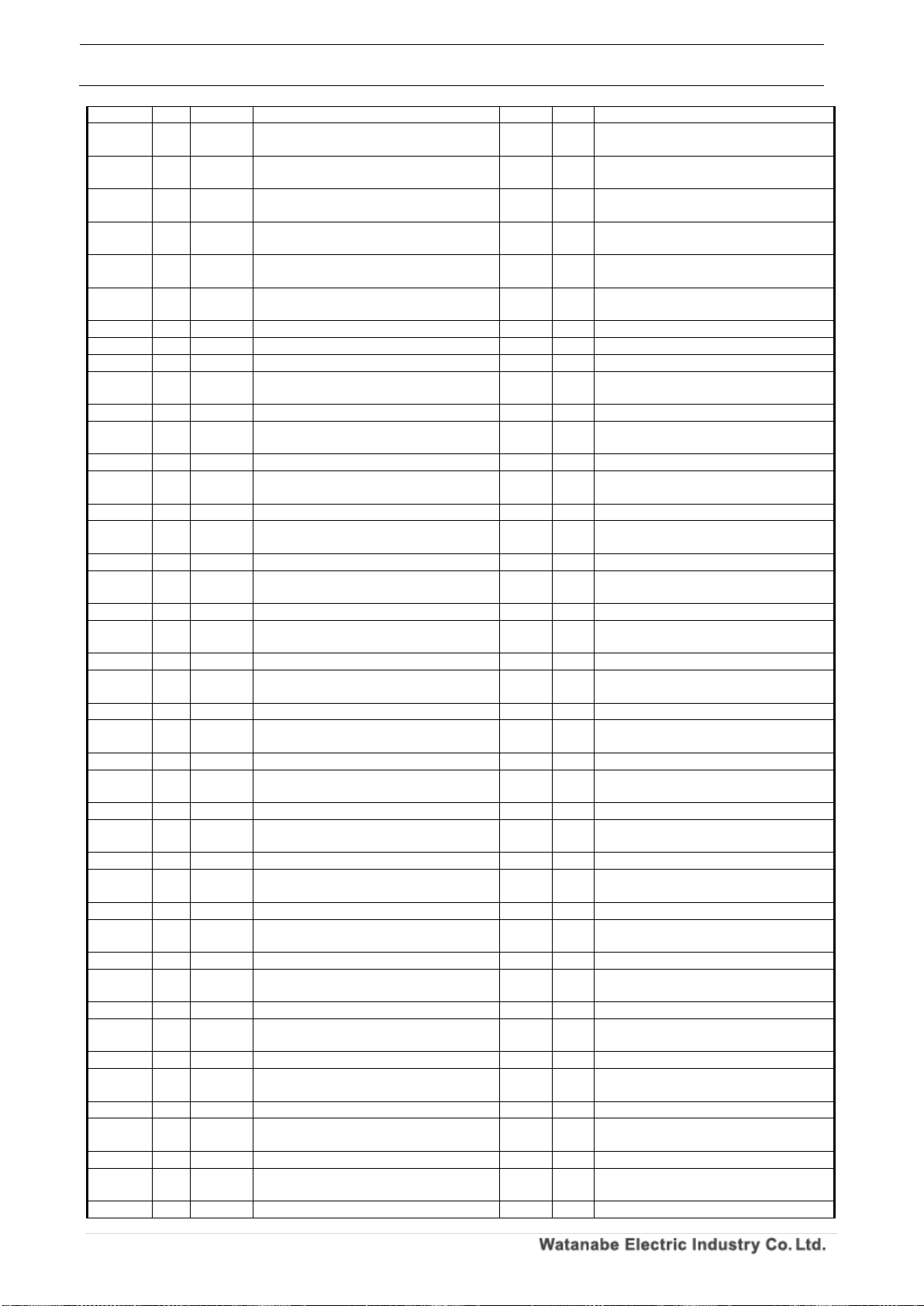
WPMZ Series Modbus communication instruction manual
IM-0862-02
Number of pages:109
71
1619 H B 7
Analog input, totalized value display unit
2
R/W
※Refer to “Pattern 1”
161A H B 7
Analog input, totalized value display Custom
unit 1st character
2
R/W
※Refer to “Pattern 1”
161B H B 7
Analog input, totalized value display Custom
unit 2nd character
2
R/W
※Refer to “Pattern 1”
161C H B 7
Analog input, totalized value display Custom
unit 3rd character
2
R/W
※Refer to “Pattern 1”
161D H B 7
Analog input, totalized value display Custom
unit 4th character
2
R/W
※Refer to “Pattern 1”
161E H B 7
Analog input, totalized value display Custom
unit 5th character
2
R/W
※Refer to “Pattern 1”
161F H B 7
Analog input, totalized value display Custom
unit 6th character
2
R/W
※Refer to “Pattern 1”
1620 H B 7
Analog input, totalized over operation
2
R/W
※Refer to “Pattern 1”
1621 H B 7
Analog input, linearize function
2
R/W
※Refer to “Pattern 1”
1622 H B 7
Analog input, linearize 1st point input value
4
R/W
※Refer to “Pattern 1”
1624 H B 7
Analog input, linearize 1st point output
value
4
R/W
※Refer to “Pattern 1”
1626 H B 7
Analog input, linearize 2nd point input value
4
R/W
※Refer to “Pattern 1”
1628 H B 7
Analog input, linearize 2nd point output
value
4
R/W
※Refer to “Pattern 1”
162A H B 7
Analog input, linearize 3rd point input value
4
R/W
※Refer to “Pattern 1”
162C H B 7
Analog input, linearize 3rd point output
value
4
R/W
※Refer to “Pattern 1”
162E H B 7
Analog input, linearize 4th point input value
4
R/W
※Refer to “Pattern 1”
1630 H B 7
Analog input, linearize 4th point output
value
4
R/W
※Refer to “Pattern 1”
1632 H B 7
Analog input, linearize 5th point input value
4
R/W
※Refer to “Pattern 1”
1634 H B 7
Analog input, linearize 5th point output
value
4
R/W
※Refer to “Pattern 1”
1636 H B 7
Analog input, linearize 6th point input value
4
R/W
※Refer to “Pattern 1”
1638 H B 7
Analog input, linearize 6th point output
value
4
R/W
※Refer to “Pattern 1”
163A H B 7
Analog input, linearize 7th point input value
4
R/W
※Refer to “Pattern 1”
163C H B 7
Analog input, linearize 7th point output
value
4
R/W
※Refer to “Pattern 1”
163E H B 7
Analog input, linearize 8th point input value
4
R/W
※Refer to “Pattern 1”
1640 H B 7
Analog input, linearize 8th point output
value
4
R/W
※Refer to “Pattern 1”
1642 H B 7
Analog input, linearize 9th point input value
4
R/W
※Refer to “Pattern 1”
1644 H B 7
Analog input, linearize 9th point output
value
4
R/W
※Refer to “Pattern 1”
1646 H B 7
Analog input, linearize 10th point input value
4
R/W
※Refer to “Pattern 1”
1648 H B 7
Analog input, linearize 10th point output
value
4
R/W
※Refer to “Pattern 1”
164A H B 7
Analog input, linearize 11th point input value
4
R/W
※Refer to “Pattern 1”
164C H B 7
Analog input, linearize 11th point output
value
4
R/W
※Refer to “Pattern 1”
164E H B 7
Analog input, linearize 12th point input value
4
R/W
※Refer to “Pattern 1”
1650 H B 7
Analog input, linearize 12th point output
value
4
R/W
※Refer to “Pattern 1”
1652 H B 7
Analog input, linearize 13th point input value
4
R/W
※Refer to “Pattern 1”
1654 H B 7
Analog input, linearize 13th point output
value
4
R/W
※Refer to “Pattern 1”
1656 H B 7
Analog input, linearize 14th point input value
4
R/W
※Refer to “Pattern 1”
1658 H B 7
Analog input, linearize 14th point output
value
4
R/W
※Refer to “Pattern 1”
165A H B 7
Analog input, linearize 15th point input value
4
R/W
※Refer to “Pattern 1”
165C H B 7
Analog input, linearize 15th point output
value
4
R/W
※Refer to “Pattern 1”
165E H B 7
Analog input, linearize 16th point input value
4
R/W
※Refer to “Pattern 1”
1660 H B 7
Analog input, linearize 16th point output
value
4
R/W
※Refer to “Pattern 1”
1662 H B 7
Analog input, linearize 17th point input value
4
R/W
※Refer to “Pattern 1”
1664 H B 7
Analog input, linearize 17th point output
value
4
R/W
※Refer to “Pattern 1”
1666 H B 7
Analog input, linearize 18th point input value
4
R/W
※Refer to “Pattern 1”
Page 73
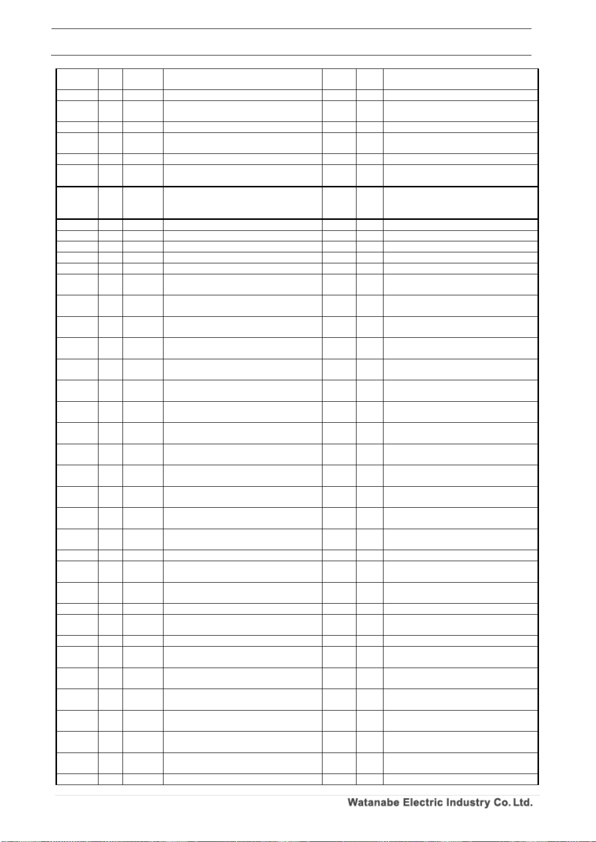
WPMZ Series Modbus communication instruction manual
IM-0862-02
Number of pages:109
72
1668 H B 7
Analog input, linearize 18th point output
value
4
R/W
※Refer to “Pattern 1”
166A H B 7
Analog input, linearize 19th point input value
4
R/W
※Refer to “Pattern 1”
166C H B 7
Analog input, linearize 19th point output
value
4
R/W
※Refer to “Pattern 1”
166E H B 7
Analog input, linearize 20th point input value
4
R/W
※Refer to “Pattern 1”
1670 H B 7
Analog input, linearize 20th point output
value
4
R/W
※Refer to “Pattern 1”
1672 H B 7
Analog input, linearize 21st point input value
4
R/W
※Refer to “Pattern 1”
1674 H B 7
Analog input, linearize 21st point output
value
4
R/W
※Refer to “Pattern 1”
1676 H
~
167FH
~ ~ Reserve
~ ~
1680 H B 8
Analog input, input range
2
R/W
※Refer to “Pattern 1”
1681 H B 8
Analog input, sensor power supply
2
R/W
※Refer to “Pattern 1”
1682 H B 8
Analog input, Low cut% value
4
R/W
※Refer to “Pattern 1”
1684 H B 8
Analog input, simple average
2
R/W
※Refer to “Pattern 1”
1685 H B 8
Analog input, moving average
2
R/W
※Refer to “Pattern 1”
1686 H B 8
Analog input, mantissa part of
instantaneous value display coefficient
4
R/W
※Refer to “Pattern 1”
1688 H B 8
Analog input, exponent part of
instantaneous value indication coefficient
2
R/W
※Refer to “Pattern 1”
1689 H B 8
Analog input, Instantaneous value Decimal
point position
2
R/W
※Refer to “Pattern 1”
168A H B 8
Analog input, instantaneous value display
unit
2
R/W
※Refer to “Pattern 1”
168B H B 8
Analog input, instantaneous value display
Custom unit 1st character
2
R/W
※Refer to “Pattern 1”
168C H B 8
Analog input, instantaneous value display
Custom unit 2nd character
2
R/W
※Refer to “Pattern 1”
168D H B 8
Analog input, instantaneous value display
Custom unit 3rd character
2
R/W
※Refer to “Pattern 1”
168E H B 8
Analog input, instantaneous value display
Custom unit 4th character
2
R/W
※Refer to “Pattern 1”
168F H B 8
Analog input, instantaneous value display
Custom unit 5th character
2
R/W
※Refer to “Pattern 1”
1690 H B 8
Analog input, instantaneous value display
Custom unit 6th character
2
R/W
※Refer to “Pattern 1”
1691 H B 8
Analog input, instantaneous value display
step
2
R/W
※Refer to “Pattern 1”
1692 H B 8
Analog input, mantissa part of totalized
value display coefficient
4
R/W
※Refer to “Pattern 1”
1694 H B 8
Analog input, exponent part of totalized
value display coefficient
2
R/W
※Refer to “Pattern 1”
1695 H B 8
Analog input, time unit of totalized unit time.
2
R/W
※Refer to “Pattern 1”
1696 H B 8
Analog input, mantissa part of integration
initial value
4
R/W
※Refer to “Pattern 1”
1698 H B 8
Analog input, exponent part of integration
initial value
2
R/W
※Refer to “Pattern 1”
1699 H B 8
Analog input, total calculation direction
2
R/W
※Refer to “Pattern 1”
169A H B 8
Analog input, totalized value Decimal point
position
2
R/W
※Refer to “Pattern 1”
169B H B 8
Analog input, totalized value display unit
2
R/W
※Refer to “Pattern 1”
169C H B 8
Analog input, totalized value display Custom
unit 1st character
2
R/W
※Refer to “Pattern 1”
169D H B 8
Analog input, totalized value display Custom
unit 2nd character
2
R/W
※Refer to “Pattern 1”
169E H B 8
Analog input, totalized value display Custom
unit 3rd character
2
R/W
※Refer to “Pattern 1”
169F H B 8
Analog input, totalized value display Custom
unit 4th character
2
R/W
※Refer to “Pattern 1”
16A0 H B 8
Analog input, totalized value display Custom
unit 5th character
2
R/W
※Refer to “Pattern 1”
16A1 H B 8
Analog input, totalized value display Custom
unit 6th character
2
R/W
※Refer to “Pattern 1”
16A2 H B 8
Analog input, totalized over operation
2
R/W
※Refer to “Pattern 1”
Page 74
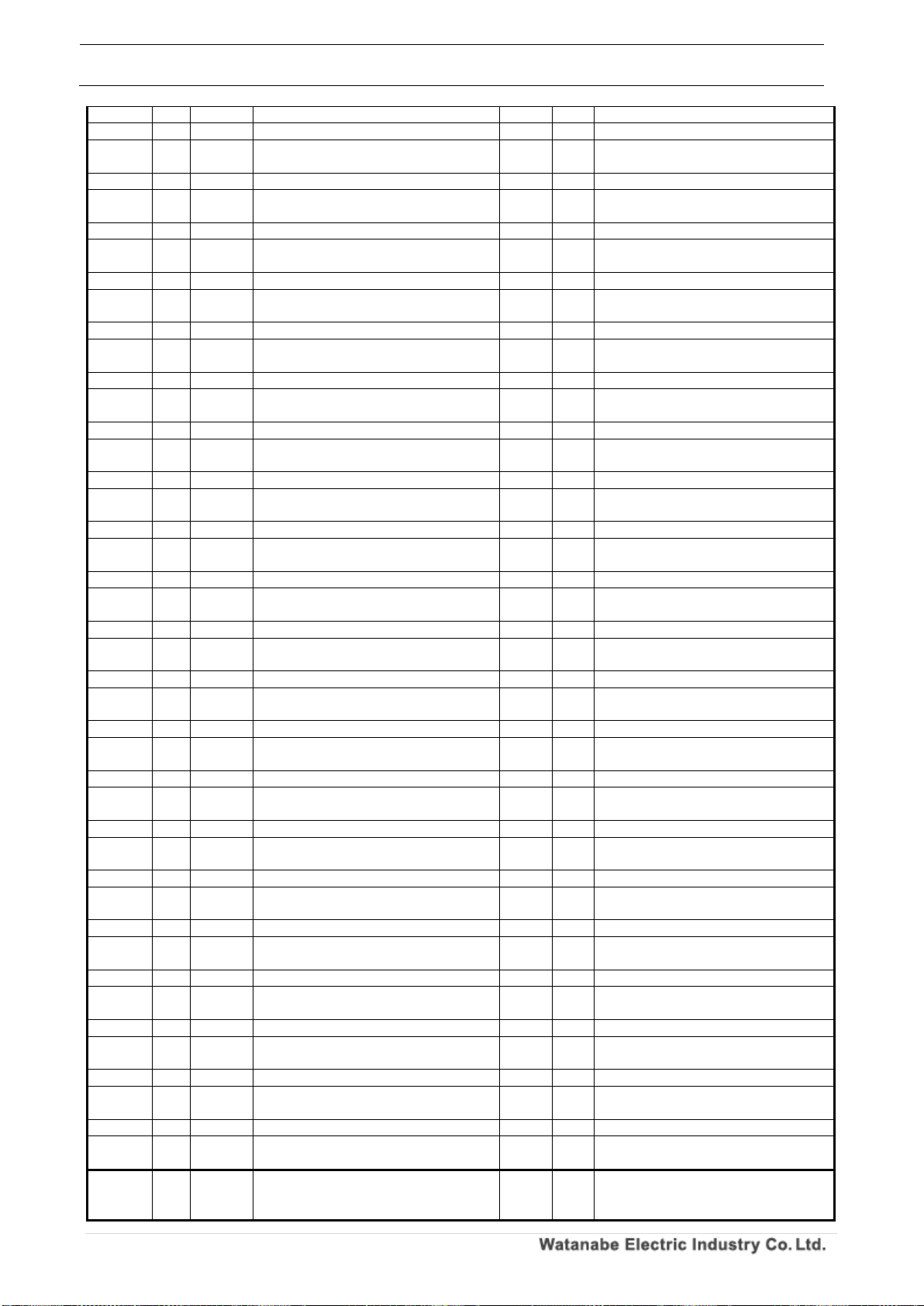
WPMZ Series Modbus communication instruction manual
IM-0862-02
Number of pages:109
73
16A3 H B 8
Analog input, linearize function
2
R/W
※Refer to “Pattern 1”
16A4 H B 8
Analog input, linearize 1st point input value
4
R/W
※Refer to “Pattern 1”
16A6 H B 8
Analog input, linearize 1st point output
value
4
R/W
※Refer to “Pattern 1”
16A8 H B 8
Analog input, linearize 2nd point input value
4
R/W
※Refer to “Pattern 1”
16AA H B 8
Analog input, linearize 2nd point output
value
4
R/W
※Refer to “Pattern 1”
16AC H B 8
Analog input, linearize 3rd point input value
4
R/W
※Refer to “Pattern 1”
16AE H B 8
Analog input, linearize 3rd point output
value
4
R/W
※Refer to “Pattern 1”
16B0 H B 8
Analog input, linearize 4th point input value
4
R/W
※Refer to “Pattern 1”
16B2 H B 8
Analog input, linearize 4th point output
value
4
R/W
※Refer to “Pattern 1”
16B4 H B 8
Analog input, linearize 5th point input value
4
R/W
※Refer to “Pattern 1”
16B6 H B 8
Analog input, linearize 5th point output
value
4
R/W
※Refer to “Pattern 1”
16B8 H B 8
Analog input, linearize 6th point input value
4
R/W
※Refer to “Pattern 1”
16BA H B 8
Analog input, linearize 6th point output
value
4
R/W
※Refer to “Pattern 1”
16BC H B 8
Analog input, linearize 7th point input value
4
R/W
※Refer to “Pattern 1”
16BE H B 8
Analog input, linearize 7th point output
value
4
R/W
※Refer to “Pattern 1”
16C0 H B 8
Analog input, linearize 8th point input value
4
R/W
※Refer to “Pattern 1”
16C2 H B 8
Analog input, linearize 8th point output
value
4
R/W
※Refer to “Pattern 1”
16C4 H B 8
Analog input, linearize 9th point input value
4
R/W
※Refer to “Pattern 1”
16C6 H B 8
Analog input, linearize 9th point output
value
4
R/W
※Refer to “Pattern 1”
16C8 H B 8
Analog input, linearize 10th point input value
4
R/W
※Refer to “Pattern 1”
16CA H B 8
Analog input, linearize 10th point output
value
4
R/W
※Refer to “Pattern 1”
16CC H B 8
Analog input, linearize 11th point input value
4
R/W
※Refer to “Pattern 1”
16CE H B 8
Analog input, linearize 11th point output
value
4
R/W
※Refer to “Pattern 1”
16D0 H B 8
Analog input, linearize 12th point input value
4
R/W
※Refer to “Pattern 1”
16D2 H B 8
Analog input, linearize 12th point output
value
4
R/W
※Refer to “Pattern 1”
16D4 H B 8
Analog input, linearize 13th point input value
4
R/W
※Refer to “Pattern 1”
16D6 H B 8
Analog input, linearize 13th point output
value
4
R/W
※Refer to “Pattern 1”
16D8 H B 8
Analog input, linearize 14th point input value
4
R/W
※Refer to “Pattern 1”
16DA H B 8
Analog input, linearize 14th point output
value
4
R/W
※Refer to “Pattern 1”
16DC H B 8
Analog input, linearize 15th point input value
4
R/W
※Refer to “Pattern 1”
16DE H B 8
Analog input, linearize 15th point output
value
4
R/W
※Refer to “Pattern 1”
16E0 H B 8
Analog input, linearize 16th point input value
4
R/W
※Refer to “Pattern 1”
16E2 H B 8
Analog input, linearize 16th point output
value
4
R/W
※Refer to “Pattern 1”
16E4 H B 8
Analog input, linearize 17th point input value
4
R/W
※Refer to “Pattern 1”
16E6 H B 8
Analog input, linearize 17th point output
value
4
R/W
※Refer to “Pattern 1”
16E8 H B 8
Analog input, linearize 18th point input value
4
R/W
※Refer to “Pattern 1”
16EA H B 8
Analog input, linearize 18th point output
value
4
R/W
※Refer to “Pattern 1”
16EC H B 8
Analog input, linearize 19th point input value
4
R/W
※Refer to “Pattern 1”
16EE H B 8
Analog input, linearize 19th point output
value
4
R/W
※Refer to “Pattern 1”
16F0 H B 8
Analog input, linearize 20th point input value
4
R/W
※Refer to “Pattern 1”
16F2 H B 8
Analog input, linearize 20th point output
value
4
R/W
※Refer to “Pattern 1”
16F4 H B 8
Analog input, linearize 21st point input value
4
R/W
※Refer to “Pattern 1”
16F6 H B 8
Analog input, linearize 21st point output
value
4
R/W
※Refer to “Pattern 1”
16F8 H
~
1701H
~ ~ Reserve
~ ~
Page 75
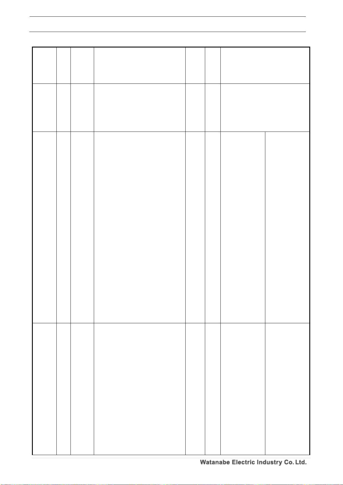
WPMZ Series Modbus communication instruction manual
IM-0862-02
Number of pages:109
74
-
1702H
-
1
2 input calculation, expression for
instantaneous value.
2
R/W
0000H:None、
0001H:AbsRatio (B/A)×100、
0002H:ErrRatio (B/A-1)×100、
0003H:Err B-A、
0004H:Dens (B/(A+B))×100、
0005H:SUM A+B
1703H
-
1
2 input calculation, instantaneous value
decimal point position.
2
R/W
0000H:None,
0001H:The lower right of the 2nd digit,
0002H:The lower right of the 3rd digit,
0003H:The lower right of the 4th digit,
0004H:The lower right of the 5th digit,
0005H:The lower right of the 6th digit ※1
※1 If the input format is "analog input" is,
6 digit of the set are not allowed.
1704H
-
1
2 input calculation, instantaneous value
display unit.
2
R/W
0000H:None、
0002H:mA、
0004H:kA、
0006H:mV、
0008H:kV、
000AH:W、
000CH:MW、
000EH:mm、
0010H:m、
0012H:kΩ、
0014H:g、
0016H:N、
0018H:MN、
001AH:kPa、
001CH:hPa、
001EH:kJ、
0020H:Hz、
0022H:MHz、
0024H:mm/s、
0026H:cm/min、
0028H:m/min、
002AH:m/s2、
002CH:m3/min、
002EH:kg/h、
0030H:kg/m3、
0032H:ℓ、
0034H:ℓ/min、
0036H:%、
0038H:%RH、
003AH:ph、
003CH:rpm、
003EH:inch、
0001H:µA、
0003H:A、
0005H:µV、
0007H:V、
0009H:VA、
000BH:kW、
000DH:µm、
000FH:cm、
0011H:Ω、
0013H:MΩ、
0015H:kg、
0017H:kN、
0019H:Pa、
001BH:Mpa、
001DH:J、
001FH:MJ、
0021H:kHz、
0023H:m3、
0025H:mm/min、
0027H:m/s、
0029H:m/h
002BH:m3/s、
002DH:m3/h、
002FH:kg/m2、
0031H:N/m2、
0033H:ℓ/s、
0035H:ℓ/h、
0037H:‰、
0039H:℃、
003BH:ppm、
003DH:t、
003FH:Custom unit
1705H
-
1
2 input calculation, instantaneous value
display custom unit 1st character.
2
R/W
0000H:None、
0002H:b、
0004H:d、
0006H:f、
0008H:h、
000AH:j、
000CH:l、
000EH:n、
0010H:p、
0012H:r、
0014H:t、
0016H:v、
0018H:x、
001AH:z、
001CH:B、
001EH:D、
0020H:F、
0022H:H、
0024H:J、
0026H:L、
0028H:N、
002AH:P、
0001H:a、
0003H:c、
0005H:e、
0007H:g、
0009H:i、
000BH:k、
000DH:m、
000FH:o、
0011H:q、
0013H:s、
0015H:u、
0017H:w、
0019H:y、
001BH:A、
001DH:C、
001FH:E、
0021H:G、
0023H:I、
0025H:K、
0027H:M、
0029H:O
002BH:Q、
Page 76
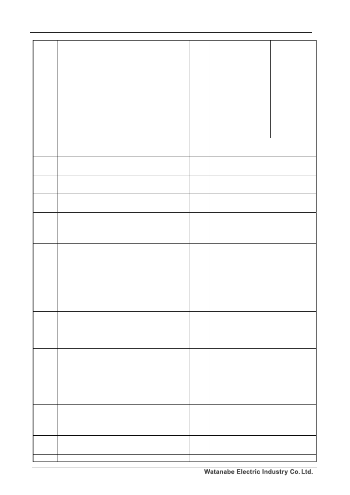
WPMZ Series Modbus communication instruction manual
IM-0862-02
Number of pages:109
75
002CH:R、
002EH:T、
0030H:V、
0032H:X、
0034H:Z、
0036H:]、
0038H:)、
003AH:2、
003CH:1、
003EH:3、
0040H:µ、
0042H:g、
0044H:/、
0046H:%、
0048H:°、
004AH:”
002DH:S、
002FH:U、
0031H:W、
0033H:Y、
0035H:[、
0037H:(、
0039H:1、
003BH:3、
003DH:2、
003FH:-、
0041H:Ω、
0043H:・、
0045H:ℓ、
0047H:‰、
0049H:’、
1706H
-
1
2 input calculation, instantaneous value
display custom unit 2nd character.
2
R/W
※Refer to “2 input calculation,
instantaneous value display custom unit
1st character.”
1707H
-
1
2 input calculation, instantaneous value
display custom unit 3rd character.
2
R/W
※Refer to “2 input calculation,
instantaneous value display custom unit
1st character.”
1708H
-
1
2 input calculation, instantaneous value
display custom unit 4th character.
2
R/W
※Refer to “2 input calculation,
instantaneous value display custom unit
1st character.”
1709H
-
1
2 input calculation, instantaneous value
display custom unit 5th character.
2
R/W
※Refer to “2 input calculation,
instantaneous value display custom unit
1st character.”
170AH
-
1
2 input calculation, instantaneous value
display custom unit 6th character.
2
R/W
※Refer to “2 input calculation,
instantaneous value display custom unit
1st character.”
170BH
-
1
2 input calculation, inistataneous value
display step.
2
R/W
0000H:None、0001H:5 steps、
0002H:10 steps
170CH
-
1
2 input calculation, expression for totalized
value.
2
R/W
0000H:None、
0001H:Add A+B、
0002H:Sub B-A
170DH
-
1
2 input calculation, totalized value decimal
point position.
2
R/W
0000H:None,
0001H:The lower right of the 2nd digit,
0002H:The lower right of the 3rd digit,
0003H:The lower right of the 4th digit,
0004H:The lower right of the 5th digit,
0005H:The lower right of the 6th digit
170EH
-
1
2 input calculation, Totalized value display
unit.
2
R/W
※Refer to “2 input calculation,
instantaneous value display unit.”
170FH - 1
2 input calculation, Totalized value display
custom unit 1st character.
2
R/W
※Refer to “2 input calculation,
instantaneous value display custom unit
1st character.”
1710H - 1
2 input calculation, Totalized value display
custom unit 2nd character.
2
R/W
※Refer to “2 input calculation,
instantaneous value display custom unit
1st character.”
1711H - 1
2 input calculation, Totalized value display
custom unit 3rd character.
2
R/W
※Refer to “2 input calculation,
instantaneous value display custom unit
1st character.”
1712H - 1
2 input calculation, Totalized value display
custom unit 4th character.
2
R/W
※Refer to “2 input calculation,
instantaneous value display custom unit
1st character.”
1713H - 1
2 input calculation, Totalized value display
custom unit 5th character.
2
R/W
※Refer to “2 input calculation,
instantaneous value display custom unit
1st character.”
1714H - 1
2 input calculation, Totalized value display
custom unit 6th character.
2
R/W
※Refer to “2 input calculation,
instantaneous value display custom unit
1st character.”
1715H - 1
2 input calculation, Totalized value overrun
count.
2
R/W
0000H:None、0001H:999 times、
0002H:Endless
1716H
~
171FH
~ ~ Reserve
~ ~ -
1720H
- 2 2 input calculation, expression for
2
R/W
※Refer to “Pattern 1”
Page 77
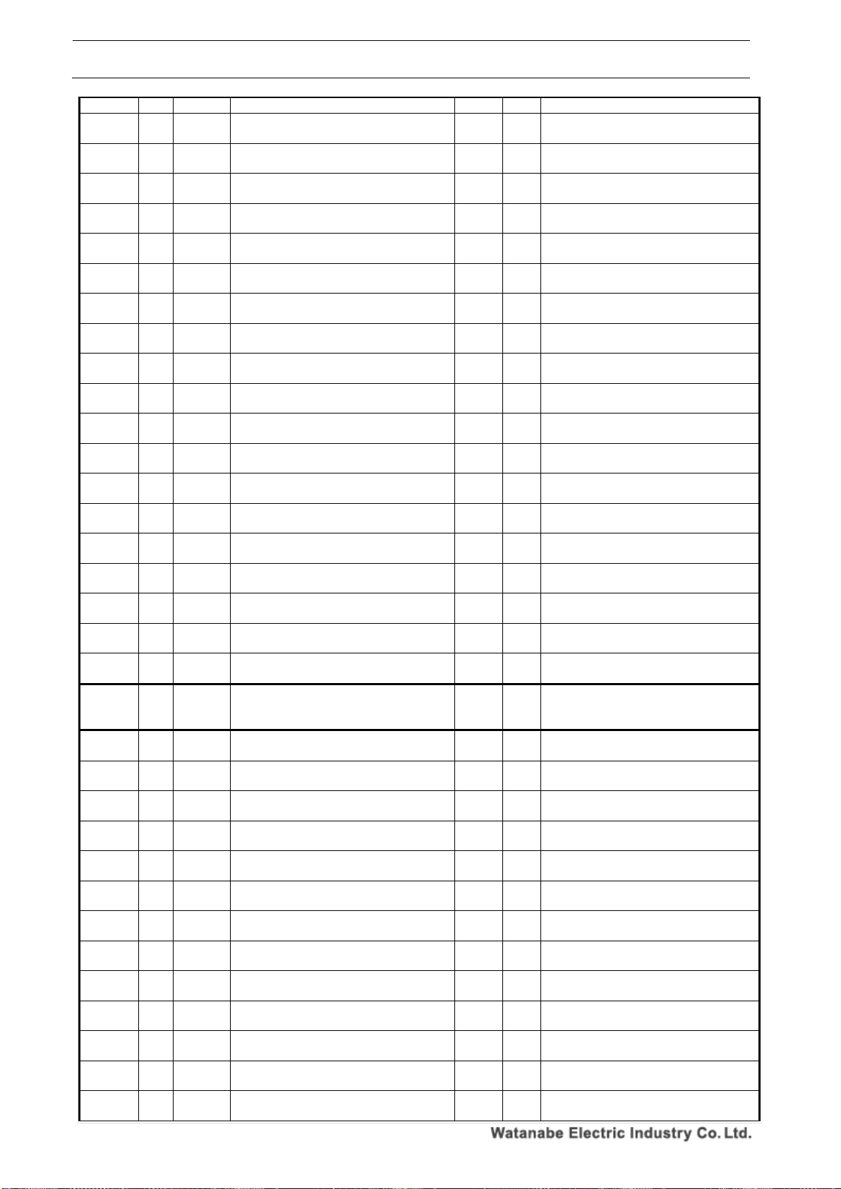
WPMZ Series Modbus communication instruction manual
IM-0862-02
Number of pages:109
76
instantaneous value.
1721H
-
2
2 input calculation, instantaneous value
decimal point position.
2
R/W
※Refer to “Pattern 1”
1722H
-
2
2 input calculation, instantaneous value
display unit.
2
R/W
※Refer to “Pattern 1”
1723H
-
2
2 input calculation, instantaneous value
display custom unit 1st character.
2
R/W
※Refer to “Pattern 1”
1724H
-
2
2 input calculation, instantaneous value
display custom unit 2nd character.
2
R/W
※Refer to “Pattern 1”
1725H
-
2
2 input calculation, instantaneous value
display custom unit 3rd character.
2
R/W
※Refer to “Pattern 1”
1726H
-
2
2 input calculation, instantaneous value
display custom unit 4th character.
2
R/W
※Refer to “Pattern 1”
1727H
-
2
2 input calculation, instantaneous value
display custom unit 5th character.
2
R/W
※Refer to “Pattern 1”
1728H
-
2
2 input calculation, instantaneous value
display custom unit 6th character.
2
R/W
※Refer to “Pattern 1”
1729H
-
2
2 input calculation, inistataneous value
display step.
2
R/W
※Refer to “Pattern 1”
172AH
-
2
2 input calculation, expression for totalized
value.
2
R/W
※Refer to “Pattern 1”
172BH
-
2
2 input calculation, totalized value decimal
point position.
2
R/W
※Refer to “Pattern 1”
172CH
-
2
2 input calculation, Totalized value display
unit.
2
R/W
※Refer to “Pattern 1”
172DH - 2
2 input calculation, Totalized value display
custom unit 1st character.
2
R/W
※Refer to “Pattern 1”
172EH - 2
2 input calculation, Totalized value display
custom unit 2nd character.
2
R/W
※Refer to “Pattern 1”
172FH - 2
2 input calculation, Totalized value display
custom unit 3rd character.
2
R/W
※Refer to “Pattern 1”
1730H - 2
2 input calculation, Totalized value display
custom unit 4th character.
2
R/W
※Refer to “Pattern 1”
1731H - 2
2 input calculation, Totalized value display
custom unit 5th character.
2
R/W
※Refer to “Pattern 1”
1732H - 2
2 input calculation, Totalized value display
custom unit 6th character.
2
R/W
※Refer to “Pattern 1”
1733H - 2
2 input calculation, Totalized value overrun
count.
2
R/W
※Refer to “Pattern 1”
1734H
~
173DH
~ ~ Reserve
~ ~
173EH
-
3
2 input calculation, expression for
instantaneous value.
2
R/W
※Refer to “Pattern 1”
173FH
-
3
2 input calculation, instantaneous value
decimal point position.
2
R/W
※Refer to “Pattern 1”
1740H
-
3
2 input calculation, instantaneous value
display unit.
2
R/W
※Refer to “Pattern 1”
1741H
-
3
2 input calculation, instantaneous value
display custom unit 1st character.
2
R/W
※Refer to “Pattern 1”
1742H
-
3
2 input calculation, instantaneous value
display custom unit 2nd character.
2
R/W
※Refer to “Pattern 1”
1743H
-
3
2 input calculation, instantaneous value
display custom unit 3rd character.
2
R/W
※Refer to “Pattern 1”
1744H
-
3
2 input calculation, instantaneous value
display custom unit 4th character.
2
R/W
※Refer to “Pattern 1”
1745H
-
3
2 input calculation, instantaneous value
display custom unit 5th character.
2
R/W
※Refer to “Pattern 1”
1746H
-
3
2 input calculation, instantaneous value
display custom unit 6th character.
2
R/W
※Refer to “Pattern 1”
1747H
-
3
2 input calculation, inistataneous value
display step.
2
R/W
※Refer to “Pattern 1”
1748H
-
3
2 input calculation, expression for totalized
value.
2
R/W
※Refer to “Pattern 1”
1749H
-
3
2 input calculation, totalized value decimal
point position.
2
R/W
※Refer to “Pattern 1”
174AH
-
3
2 input calculation, Totalized value display
unit.
2
R/W
※Refer to “Pattern 1”
Page 78
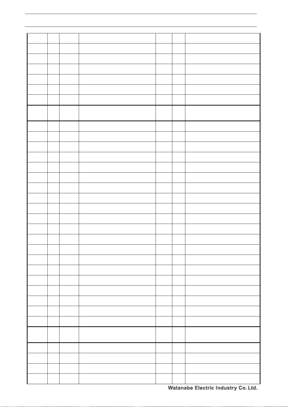
WPMZ Series Modbus communication instruction manual
IM-0862-02
Number of pages:109
77
174BH - 3
2 input calculation, Totalized value display
custom unit 1st character.
2
R/W
※Refer to “Pattern 1”
174CH - 3
2 input calculation, Totalized value display
custom unit 2nd character.
2
R/W
※Refer to “Pattern 1”
174DH - 3
2 input calculation, Totalized value display
custom unit 3rd character.
2
R/W
※Refer to “Pattern 1”
174EH - 3
2 input calculation, Totalized value display
custom unit 4th character.
2
R/W
※Refer to “Pattern 1”
174FH - 3
2 input calculation, Totalized value display
custom unit 5th character.
2
R/W
※Refer to “Pattern 1”
1750H - 3
2 input calculation, Totalized value display
custom unit 6th character.
2
R/W
※Refer to “Pattern 1”
1751H - 3
2 input calculation, Totalized value overrun
count.
2
R/W
※Refer to “Pattern 1”
1752H
~
175BH
~ ~ Reserve
~ ~
175CH
-
4
2 input calculation, expression for
instantaneous value.
2
R/W
※Refer to “Pattern 1”
175DH
-
4
2 input calculation, instantaneous value
decimal point position.
2
R/W
※Refer to “Pattern 1”
175EH
-
4
2 input calculation, instantaneous value
display unit.
2
R/W
※Refer to “Pattern 1”
175FH
-
4
2 input calculation, instantaneous value
display custom unit 1st character.
2
R/W
※Refer to “Pattern 1”
1760H
-
4
2 input calculation, instantaneous value
display custom unit 2nd character.
2
R/W
※Refer to “Pattern 1”
1761H
-
4
2 input calculation, instantaneous value
display custom unit 3rd character.
2
R/W
※Refer to “Pattern 1”
1762H
-
4
2 input calculation, instantaneous value
display custom unit 4th character.
2
R/W
※Refer to “Pattern 1”
1763H
-
4
2 input calculation, instantaneous value
display custom unit 5th character.
2
R/W
※Refer to “Pattern 1”
1764H
-
4
2 input calculation, instantaneous value
display custom unit 6th character.
2
R/W
※Refer to “Pattern 1”
1765H
-
4
2 input calculation, inistataneous value
display step.
2
R/W
※Refer to “Pattern 1”
1766H
-
4
2 input calculation, expression for totalized
value.
2
R/W
※Refer to “Pattern 1”
1767H
-
4
2 input calculation, totalized value decimal
point position.
2
R/W
※Refer to “Pattern 1”
1768H
-
4
2 input calculation, Totalized value display
unit.
2
R/W
※Refer to “Pattern 1”
1769H - 4
2 input calculation, Totalized value display
custom unit 1st character.
2
R/W
※Refer to “Pattern 1”
176AH - 4
2 input calculation, Totalized value display
custom unit 2nd character.
2
R/W
※Refer to “Pattern 1”
176BH - 4
2 input calculation, Totalized value display
custom unit 3rd character.
2
R/W
※Refer to “Pattern 1”
176CH - 4
2 input calculation, Totalized value display
custom unit 4th character.
2
R/W
※Refer to “Pattern 1”
176DH - 4
2 input calculation, Totalized value display
custom unit 5th character.
2
R/W
※Refer to “Pattern 1”
176EH - 4
2 input calculation, Totalized value display
custom unit 6th character.
2
R/W
※Refer to “Pattern 1”
176FH - 4
2 input calculation, Totalized value overrun
count.
2
R/W
※Refer to “Pattern 1”
1770H
~
1779H
~ ~ Reserve
~ ~
177AH
-
5
2 input calculation, expression for
instantaneous value.
2
R/W
※Refer to “Pattern 1”
177BH
-
5
2 input calculation, instantaneous value
decimal point position.
2
R/W
※Refer to “Pattern 1”
177CH
-
5
2 input calculation, instantaneous value
display unit.
2
R/W
※Refer to “Pattern 1”
177DH
-
5
2 input calculation, instantaneous value
display custom unit 1st character.
2
R/W
※Refer to “Pattern 1”
Page 79
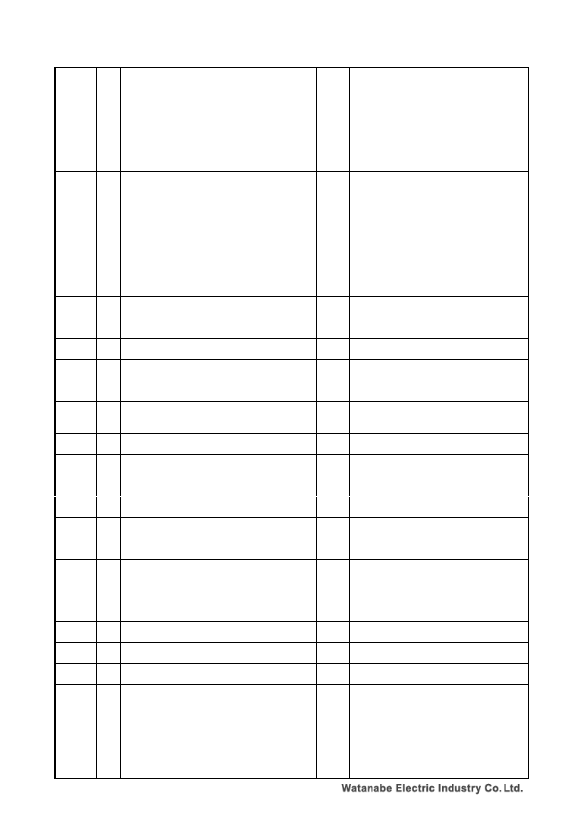
WPMZ Series Modbus communication instruction manual
IM-0862-02
Number of pages:109
78
177EH
-
5
2 input calculation, instantaneous value
display custom unit 2nd character.
2
R/W
※Refer to “Pattern 1”
177FH
-
5
2 input calculation, instantaneous value
display custom unit 3rd character.
2
R/W
※Refer to “Pattern 1”
1780H
-
5
2 input calculation, instantaneous value
display custom unit 4th character.
2
R/W
※Refer to “Pattern 1”
1781H
-
5
2 input calculation, instantaneous value
display custom unit 5th character.
2
R/W
※Refer to “Pattern 1”
1782H
-
5
2 input calculation, instantaneous value
display custom unit 6th character.
2
R/W
※Refer to “Pattern 1”
1783H
-
5
2 input calculation, inistataneous value
display step.
2
R/W
※Refer to “Pattern 1”
1784H
-
5
2 input calculation, expression for totalized
value.
2
R/W
※Refer to “Pattern 1”
1785H
-
5
2 input calculation, totalized value decimal
point position.
2
R/W
※Refer to “Pattern 1”
1786H
-
5
2 input calculation, Totalized value display
unit.
2
R/W
※Refer to “Pattern 1”
1787H - 5
2 input calculation, Totalized value display
custom unit 1st character.
2
R/W
※Refer to “Pattern 1”
1788H - 5
2 input calculation, Totalized value display
custom unit 2nd character.
2
R/W
※Refer to “Pattern 1”
1789H - 5
2 input calculation, Totalized value display
custom unit 3rd character.
2
R/W
※Refer to “Pattern 1”
178AH - 5
2 input calculation, Totalized value display
custom unit 4th character.
2
R/W
※Refer to “Pattern 1”
178BH - 5
2 input calculation, Totalized value display
custom unit 5th character.
2
R/W
※Refer to “Pattern 1”
178CH - 5
2 input calculation, Totalized value display
custom unit 6th character.
2
R/W
※Refer to “Pattern 1”
178DH - 5
2 input calculation, Totalized value overrun
count.
2
R/W
※Refer to “Pattern 1”
178EH
~
1797H
~ ~ Reserve
~ ~
1798H
-
6
2 input calculation, expression for
instantaneous value.
2
R/W
※Refer to “Pattern 1”
1799H
-
6
2 input calculation, instantaneous value
decimal point position.
2
R/W
※Refer to “Pattern 1”
179AH
-
6
2 input calculation, instantaneous value
display unit.
2
R/W
※Refer to “Pattern 1”
179BH
-
6
2 input calculation, instantaneous value
display custom unit 1st character.
2
R/W
※Refer to “Pattern 1”
179CH
-
6
2 input calculation, instantaneous value
display custom unit 2nd character.
2
R/W
※Refer to “Pattern 1”
179DH
-
6
2 input calculation, instantaneous value
display custom unit 3rd character.
2
R/W
※Refer to “Pattern 1”
179EH
-
6
2 input calculation, instantaneous value
display custom unit 4th character.
2
R/W
※Refer to “Pattern 1”
179FH
-
6
2 input calculation, instantaneous value
display custom unit 5th character.
2
R/W
※Refer to “Pattern 1”
17A0H
-
6
2 input calculation, instantaneous value
display custom unit 6th character.
2
R/W
※Refer to “Pattern 1”
17A1H
-
6
2 input calculation, inistataneous value
display step.
2
R/W
※Refer to “Pattern 1”
17A2H
-
6
2 input calculation, expression for totalized
value.
2
R/W
※Refer to “Pattern 1”
17A3H
-
6
2 input calculation, totalized value decimal
point position.
2
R/W
※Refer to “Pattern 1”
17A4H
-
6
2 input calculation, Totalized value display
unit.
2
R/W
※Refer to “Pattern 1”
17A5H - 6
2 input calculation, Totalized value display
custom unit 1st character.
2
R/W
※Refer to “Pattern 1”
17A6H - 6
2 input calculation, Totalized value display
custom unit 2nd character.
2
R/W
※Refer to “Pattern 1”
17A7H - 6
2 input calculation, Totalized value display
custom unit 3rd character.
2
R/W
※Refer to “Pattern 1”
17A8H - 6
2 input calculation, Totalized value display
2
R/W
※Refer to “Pattern 1”
Page 80
WPMZ Series Modbus communication instruction manual
IM-0862-02
Number of pages:109
79
custom unit 4th character.
17A9H - 6
2 input calculation, Totalized value display
custom unit 5th character.
2
R/W
※Refer to “Pattern 1”
17AAH - 6
2 input calculation, Totalized value display
custom unit 6th character.
2
R/W
※Refer to “Pattern 1”
17ABH - 6
2 input calculation, Totalized value overrun
count.
2
R/W
※Refer to “Pattern 1”
17ACH
~
17B5H
~ ~ Reserve
~ ~
17B6H
-
7
2 input calculation, expression for
instantaneous value.
2
R/W
※Refer to “Pattern 1”
17B7H
-
7
2 input calculation, instantaneous value
decimal point position.
2
R/W
※Refer to “Pattern 1”
17B8H
-
7
2 input calculation, instantaneous value
display unit.
2
R/W
※Refer to “Pattern 1”
17B9H
-
7
2 input calculation, instantaneous value
display custom unit 1st character.
2
R/W
※Refer to “Pattern 1”
17BAH
-
7
2 input calculation, instantaneous value
display custom unit 2nd character.
2
R/W
※Refer to “Pattern 1”
17BBH
-
7
2 input calculation, instantaneous value
display custom unit 3rd character.
2
R/W
※Refer to “Pattern 1”
17BCH
-
7
2 input calculation, instantaneous value
display custom unit 4th character.
2
R/W
※Refer to “Pattern 1”
17BDH
-
7
2 input calculation, instantaneous value
display custom unit 5th character.
2
R/W
※Refer to “Pattern 1”
17BEH
-
7
2 input calculation, instantaneous value
display custom unit 6th character.
2
R/W
※Refer to “Pattern 1”
17BFH
-
7
2 input calculation, inistataneous value
display step.
2
R/W
※Refer to “Pattern 1”
17C0H
-
7
2 input calculation, expression for totalized
value.
2
R/W
※Refer to “Pattern 1”
17C1H
-
7
2 input calculation, totalized value decimal
point position.
2
R/W
※Refer to “Pattern 1”
17C2H
-
7
2 input calculation, Totalized value display
unit.
2
R/W
※Refer to “Pattern 1”
17C3H - 7
2 input calculation, Totalized value display
custom unit 1st character.
2
R/W
※Refer to “Pattern 1”
17C4H - 7
2 input calculation, Totalized value display
custom unit 2nd character.
2
R/W
※Refer to “Pattern 1”
17C5H - 7
2 input calculation, Totalized value display
custom unit 3rd character.
2
R/W
※Refer to “Pattern 1”
17C6H - 7
2 input calculation, Totalized value display
custom unit 4th character.
2
R/W
※Refer to “Pattern 1”
17C7H - 7
2 input calculation, Totalized value display
custom unit 5th character.
2
R/W
※Refer to “Pattern 1”
17C8H - 7
2 input calculation, Totalized value display
custom unit 6th character.
2
R/W
※Refer to “Pattern 1”
17C9H - 7
2 input calculation, Totalized value overrun
count.
2
R/W
※Refer to “Pattern 1”
17ACH
~
17D3H
~ ~ Reserve
~ ~
17D4H
-
8
2 input calculation, expression for
instantaneous value.
2
R/W
※Refer to “Pattern 1”
17D5H
-
8
2 input calculation, instantaneous value
decimal point position.
2
R/W
※Refer to “Pattern 1”
17D6H
-
8
2 input calculation, instantaneous value
display unit.
2
R/W
※Refer to “Pattern 1”
17D7H
-
8
2 input calculation, instantaneous value
display custom unit 1st character.
2
R/W
※Refer to “Pattern 1”
17D8H
-
8
2 input calculation, instantaneous value
display custom unit 2nd character.
2
R/W
※Refer to “Pattern 1”
17D9H
-
8
2 input calculation, instantaneous value
display custom unit 3rd character.
2
R/W
※Refer to “Pattern 1”
17DAH
-
8
2 input calculation, instantaneous value
display custom unit 4th character.
2
R/W
※Refer to “Pattern 1”
17DBH
- 8 2 input calculation, instantaneous value
2
R/W
※Refer to “Pattern 1”
Page 81
WPMZ Series Modbus communication instruction manual
IM-0862-02
Number of pages:109
80
display custom unit 5th character.
17DCH
-
8
2 input calculation, instantaneous value
display custom unit 6th character.
2
R/W
※Refer to “Pattern 1”
17DDH
-
8
2 input calculation, inistataneous value
display step.
2
R/W
※Refer to “Pattern 1”
17DEH
-
8
2 input calculation, expression for totalized
value.
2
R/W
※Refer to “Pattern 1”
17DFH
-
8
2 input calculation, totalized value decimal
point position.
2
R/W
※Refer to “Pattern 1”
17E0H
-
8
2 input calculation, Totalized value display
unit.
2
R/W
※Refer to “Pattern 1”
17E1H - 8
2 input calculation, Totalized value display
custom unit 1st character.
2
R/W
※Refer to “Pattern 1”
17E2H - 8
2 input calculation, Totalized value display
custom unit 2nd character.
2
R/W
※Refer to “Pattern 1”
17E3H - 8
2 input calculation, Totalized value display
custom unit 3rd character.
2
R/W
※Refer to “Pattern 1”
17E4H - 8
2 input calculation, Totalized value display
custom unit 4th character.
2
R/W
※Refer to “Pattern 1”
17E5H - 8
2 input calculation, Totalized value display
custom unit 5th character.
2
R/W
※Refer to “Pattern 1”
17E6H - 8
2 input calculation, Totalized value display
custom unit 6th character.
2
R/W
※Refer to “Pattern 1”
17E7H - 8
2 input calculation, Totalized value overrun
count.
2
R/W
※Refer to “Pattern 1”
17E8H
~
17F1H
~ ~ Reserve
~ ~
-
17F2H - -
ExtCtrl1Func
2
R/W
0000H:None、
0001H:CompareReset、
0002H:TotalResetA ※2、
0003H:TotalResetB ※1, 2、
0004H:TotalResetA&B ※1, 2、
0005H:MeasureBlockA、
0006H:MeasureBlockB ※1、
0007H:MeasureBlockA&B ※1、
0008H:DispHoldA、
0009H:DispHoldB ※1、
000AH:DispHoldA&B ※1、
000BH:MaxHoldA、
000CH:MaxHoldB ※1、
000DH:MaxHoldA&B ※1、
000EH:MinHoldA、
000FH:MinHoldB ※1、
0010H:MinHoldA&B ※1、
0011H:MonitorChange、
0012H:TrendHold、
0013H:PatternChange1、
0014H:PatternChange 2、
0015H:PatternChange 3、
0016H:Digital zero A ※3、
0017H:Digital zero B ※1 ※4、
0018H:Digital zero A&B ※1 ※5、
※1 When input Bch is none, the setting is
not available.
※2 In the case of “WPMZ-5”, the setting
is not available.
※3 In case of input Ach is other than
"analog input", the setting is not available
※4 In case of input Bch is other than
"analog input", the setting is not available.
※5 In case of input Ach and Bch are
other than "analog input", the setting is
not available.
17F3H - -
ExtCtrl2Func
2
R/W
※Refer to ExtCtrl1Func
17F4H - -
ExtCtrl3Func
2
R/W
※Refer to ExtCtrl1Func
Page 82
WPMZ Series Modbus communication instruction manual
IM-0862-02
Number of pages:109
81
17F5H - -
ExtCtrl4Func
2
R/W
※Refer to ExtCtrl1Func
17F6H - -
ExtCtrl5Func
2
R/W
※Refer to ExtCtrl1Func
17F7H
~
17FBH
~ ~ Reserve
~ ~
17FCH
AL1 1 OutputDispValue
2
R/W
0000H:None、
0001H:InsA
0002H:InsB ※1、
0003H:InsCalc ※1、
0004H:TotA ※2、
0005H:TotB ※1, 2、
0006H:TotCalc ※1, 2
※1 When input chB is none, the setting
is not available.
※2 In the case of “WPMZ5”, the setting
is not available.
17FDH
AL1 1 CompareMode
2
R/W
0000H:LevelJudge、
0001H:ZoneJudge
17FEH
AL1 1 OnConditions-LevelJudge
2
R/W
0000H:Excess、0001H:LessThan
17FFH
AL1 1 Threshold-LevelJudge
4
R/W
-999,999~999,999
1801H
AL1 1 Hysteresis-LevelJudge
4
R/W
0~999,999
1803H
AL1 1 OnConditions-ZoneJudge
2
R/W
0000H:InTheZone、
0001H:OutsideTheZone
1804H
AL1 1 Zone upper limit-ZoneJudge
4
R/W
-999,999~999,999
1806H
AL1 1 Zone lower limit-ZoneJudge
4
R/W
-999,999~999,999
1808H
AL1 1 Hysteresis-ZoneJudge
4
R/W
0~999,999
180AH
AL1 1 OnDelay
2
R/W
0000H:None、0001H:20ms、
0002H:50ms、0003H:100ms、
0004H:200ms、0005H:500ms、
0006H:1s、0007H:5s、
0008H:10s、0009H:20s
180BH
AL1 1 OffDelay
2
R/W
0000H:None、0001H:20ms、
0002H:50ms、0003H:100ms、
0004H:200ms、0005H:500ms、
0006H:1s、0007H:5s、
0008H:10s、0009H:20s
180CH
AL1 1 OutputMode
2
R/W
0000H:Normal、0001H:Latch、
0002H:OneShot5ms、
0003H:OneShot 10ms、
0004H:OneShot 20ms、
0005H:OneShot 50ms、
0006H:OneShot 0.1s、
0007H:OneShot 0.2s、
0008H:OneShot 0.5s、
0009H:OneShot 1s、
000AH:OneShot 2s
180DH
AL1 1 OutputLogic
2
R/W
0000H:Positive(NC)、0001H:Negative(NO)
(NC/NO are for relay output product)
180EH
AL1 1 OnBgColors
2
R/W
0000H:Black、0001H:Red、
0002H:Yellow、0003H:Green
180FH
~
181BH
~ ~ Reserve
~ ~
181AH
AL1 2 OutputDispValue
2
R/W
※Refer to Pattern1
181BH
AL1 2 CompareMode
2
R/W
※Refer to Pattern1
181CH
AL1 2 OnConditions-LevelJudge
2
R/W
※Refer to Pattern1
181DH
AL1 2 Threshold-LevelJudge
4
R/W
※Refer to Pattern1
181FH
AL1 2 Hysteresis-LevelJudge
4
R/W
※Refer to Pattern1
1821H
AL1 2 OnConditions-ZoneJudge
2
R/W
※Refer to Pattern1
1822H
AL1 2 Zone upper limit-ZoneJudge
4
R/W
※Refer to Pattern1
1824H
AL1 2 Zone lower limit-ZoneJudge
4
R/W
※Refer to Pattern1
1826H
AL1 2 Hysteresis-ZoneJudge
4
R/W
※Refer to Pattern1
1828H
AL1 2 OnDelay
2
R/W
※Refer to Pattern1
1829H
AL1 2 OffDelay
2
R/W
※Refer to Pattern1
182AH
AL1 2 OutputMode
2
R/W
※Refer to Pattern1
182BH
AL1 2 OutputLogic
2
R/W
※Refer to Pattern1
Page 83
WPMZ Series Modbus communication instruction manual
IM-0862-02
Number of pages:109
82
182CH
AL1 2 OnBgColors
2
R/W
※Refer to Pattern1
182DH
~
1837H
~ ~ Reserve
~ ~
1838H
AL1 3 OutputDispValue
2
R/W
※Refer to Pattern1
1839H
AL1 3 CompareMode
2
R/W
※Refer to Pattern1
183AH
AL1 3 OnConditions-LevelJudge
2
R/W
※Refer to Pattern1
183BH
AL1 3 Threshold-LevelJudge
4
R/W
※Refer to Pattern1
183DH
AL1 3 Hysteresis-LevelJudge
4
R/W
※Refer to Pattern1
183FH
AL1 3 OnConditions-ZoneJudge
2
R/W
※Refer to Pattern1
1840H
AL1 3 Zone upper limit-ZoneJudge
4
R/W
※Refer to Pattern1
1842H
AL1 3 Zone lower limit-ZoneJudge
4
R/W
※Refer to Pattern1
1844H
AL1 3 Hysteresis-ZoneJudge
4
R/W
※Refer to Pattern1
1846H
AL1 3 OnDelay
2
R/W
※Refer to Pattern1
1847H
AL1 3 OffDelay
2
R/W
※Refer to Pattern1
1848H
AL1 3 OutputMode
2
R/W
※Refer to Pattern1
1849H
AL1 3 OutputLogic
2
R/W
※Refer to Pattern1
184AH
AL1 3 OnBgColors
2
R/W
※Refer to Pattern1
184BH
~
1855H
~ ~ Reserve
~ ~
1856H
AL1 4 OutputDispValue
2
R/W
※Refer to Pattern1
1857H
AL1 4 CompareMode
2
R/W
※Refer to Pattern1
1858H
AL1 4 OnConditions-LevelJudge
2
R/W
※Refer to Pattern1
1859H
AL1 4 Threshold-LevelJudge
4
R/W
※Refer to Pattern1
185BH
AL1 4 Hysteresis-LevelJudge
4
R/W
※Refer to Pattern1
185DH
AL1 4 OnConditions-ZoneJudge
2
R/W
※Refer to Pattern1
185EH
AL1 4 Zone upper limit-ZoneJudge
4
R/W
※Refer to Pattern1
1860H
AL1 4 Zone lower limit-ZoneJudge
4
R/W
※Refer to Pattern1
1862H
AL1 4 Hysteresis-ZoneJudge
4
R/W
※Refer to Pattern1
1864H
AL1 4 OnDelay
2
R/W
※Refer to Pattern1
1865H
AL1 4 OffDelay
2
R/W
※Refer to Pattern1
1866H
AL1 4 OutputMode
2
R/W
※Refer to Pattern1
1867H
AL1 4 OutputLogic
2
R/W
※Refer to Pattern1
1868H
AL1 4 OnBgColors
2
R/W
※Refer to Pattern1
1867H
~
1873H
~ ~ Reserve
~ ~
1874H
AL1 5 OutputDispValue
2
R/W
※Refer to Pattern1
1875H
AL1 5 CompareMode
2
R/W
※Refer to Pattern1
1876H
AL1 5 OnConditions-LevelJudge
2
R/W
※Refer to Pattern1
1877H
AL1 5 Threshold-LevelJudge
4
R/W
※Refer to Pattern1
1879H
AL1 5 Hysteresis-LevelJudge
4
R/W
※Refer to Pattern1
187BH
AL1 5 OnConditions-ZoneJudge
2
R/W
※Refer to Pattern1
187CH
AL1 5 Zone upper limit-ZoneJudge
4
R/W
※Refer to Pattern1
187EH
AL1 5 Zone lower limit-ZoneJudge
4
R/W
※Refer to Pattern1
1880H
AL1 5 Hysteresis-ZoneJudge
4
R/W
※Refer to Pattern1
1882H
AL1 5 OnDelay
2
R/W
※Refer to Pattern1
1883H
AL1 5 OffDelay
2
R/W
※Refer to Pattern1
1884H
AL1 5 OutputMode
2
R/W
※Refer to Pattern1
1885H
AL1 5 OutputLogic
2
R/W
※Refer to Pattern1
1886H
AL1 5 OnBgColors
2
R/W
※Refer to Pattern1
1887H
~
1891H
~ ~ Reserve
~ ~
1892H
AL1 6 OutputDispValue
2
R/W
※Refer to Pattern1
1893H
AL1 6 CompareMode
2
R/W
※Refer to Pattern1
1894H
AL1 6 OnConditions-LevelJudge
2
R/W
※Refer to Pattern1
1895H
AL1 6 Threshold-LevelJudge
4
R/W
※Refer to Pattern1
1897H
AL1 6 Hysteresis-LevelJudge
4
R/W
※Refer to Pattern1
1899H
AL1 6 OnConditions-ZoneJudge
2
R/W
※Refer to Pattern1
189AH
AL1 6 Zone upper limit-ZoneJudge
4
R/W
※Refer to Pattern1
189CH
AL1 6 Zone lower limit-ZoneJudge
4
R/W
※Refer to Pattern1
189EH
AL1 6 Hysteresis-ZoneJudge
4
R/W
※Refer to Pattern1
18A0H
AL1 6 OnDelay
2
R/W
※Refer to Pattern1
18A1H
AL1 6 OffDelay
2
R/W
※Refer to Pattern1
Page 84
WPMZ Series Modbus communication instruction manual
IM-0862-02
Number of pages:109
83
18A2H
AL1 6 OutputMode
2
R/W
※Refer to Pattern1
18A3H
AL1 6 OutputLogic
2
R/W
※Refer to Pattern1
18A4H
AL1 6 OnBgColors
2
R/W
※Refer to Pattern1
18A5H
~
18AFH
~ ~ Reserve
~ ~
18B0H
AL1 7 OutputDispValue
2
R/W
※Refer to Pattern1
18B1H
AL1 7 CompareMode
2
R/W
※Refer to Pattern1
18B2H
AL1 7 OnConditions-LevelJudge
2
R/W
※Refer to Pattern1
18B3H
AL1 7 Threshold-LevelJudge
4
R/W
※Refer to Pattern1
18B5H
AL1 7 Hysteresis-LevelJudge
4
R/W
※Refer to Pattern1
18B7H
AL1 7 OnConditions-ZoneJudge
2
R/W
※Refer to Pattern1
18B8H
AL1 7 Zone upper limit-ZoneJudge
4
R/W
※Refer to Pattern1
18BAH
AL1 7 Zone lower limit-ZoneJudge
4
R/W
※Refer to Pattern1
18BCH
AL1 7 Hysteresis-ZoneJudge
4
R/W
※Refer to Pattern1
18BEH
AL1 7 OnDelay
2
R/W
※Refer to Pattern1
18BFH
AL1 7 OffDelay
2
R/W
※Refer to Pattern1
18C0H
AL1 7 OutputMode
2
R/W
※Refer to Pattern1
18C1H
AL1 7 OutputLogic
2
R/W
※Refer to Pattern1
18C2H
AL1 7 OnBgColors
2
R/W
※Refer to Pattern1
18C3H
~
18CDH
~ ~ Reserve
~ ~
18CEH
AL1 8 OutputDispValue
2
R/W
※Refer to Pattern1
18CFH
AL1 8 CompareMode
2
R/W
※Refer to Pattern1
18D0H
AL1 8 OnConditions-LevelJudge
2
R/W
※Refer to Pattern1
18D1H
AL1 8 Threshold-LevelJudge
4
R/W
※Refer to Pattern1
18D3H
AL1 8 Hysteresis-LevelJudge
4
R/W
※Refer to Pattern1
18D5H
AL1 8 OnConditions-ZoneJudge
2
R/W
※Refer to Pattern1
18D6H
AL1 8 Zone upper limit-ZoneJudge
4
R/W
※Refer to Pattern1
18D8H
AL1 8 Zone lower limit-ZoneJudge
4
R/W
※Refer to Pattern1
18DAH
AL1 8 Hysteresis-ZoneJudge
4
R/W
※Refer to Pattern1
18DCH
AL1 8 OnDelay
2
R/W
※Refer to Pattern1
18DDH
AL1 8 OffDelay
2
R/W
※Refer to Pattern1
18DEH
AL1 8 OutputMode
2
R/W
※Refer to Pattern1
18DFH
AL1 8 OutputLogic
2
R/W
※Refer to Pattern1
18E0H
AL1 8 OnBgColors
2
R/W
※Refer to Pattern1
18E1H
~
18EBH
~ ~ Reserve
~ ~
-
18ECH
AL2 1 OutputDispValue
2
R/W
※Refer to Pattern1
18EDH
AL2 1 CompareMode
2
R/W
※Refer to Pattern1
18EEH
AL2 1 OnConditions-LevelJudge
2
R/W
※Refer to Pattern1
18EFH
AL2 1 Threshold-LevelJudge
4
R/W
※Refer to Pattern1
18F1H
AL2 1 Hysteresis-LevelJudge
4
R/W
※Refer to Pattern1
18F3H
AL2 1 OnConditions-ZoneJudge
2
R/W
※Refer to Pattern1
18F4H
AL2 1 Zone upper limit-ZoneJudge
4
R/W
※Refer to Pattern1
18F6H
AL2 1 Zone lower limit-ZoneJudge
4
R/W
※Refer to Pattern1
18F8H
AL2 1 Hysteresis-ZoneJudge
4
R/W
※Refer to Pattern1
18FAH
AL2 1 OnDelay
2
R/W
※Refer to Pattern1
18FBH
AL2 1 OffDelay
2
R/W
※Refer to Pattern1
18FCH
AL2 1 OutputMode
2
R/W
※Refer to Pattern1
18FDH
AL2 1 OutputLogic
2
R/W
※Refer to Pattern1
18FEH
AL2 1 OnBgColors
2
R/W
※Refer to Pattern1
18FFH
~
1909H
~ ~ Reserve
~ ~
190AH
AL2 2 OutputDispValue
2
R/W
※Refer to Pattern1
190BH
AL2 2 CompareMode
2
R/W
※Refer to Pattern1
190CH
AL2 2 OnConditions-LevelJudge
2
R/W
※Refer to Pattern1
190DH
AL2 2 Threshold-LevelJudge
4
R/W
※Refer to Pattern1
190FH
AL2 2 Hysteresis-LevelJudge
4
R/W
※Refer to Pattern1
1911H
AL2 2 OnConditions-ZoneJudge
2
R/W
※Refer to Pattern1
1912H
AL2 2 Zone upper limit-ZoneJudge
4
R/W
※Refer to Pattern1
1914H
AL2 2 Zone lower limit-ZoneJudge
4
R/W
※Refer to Pattern1
Page 85
WPMZ Series Modbus communication instruction manual
IM-0862-02
Number of pages:109
84
1916H
AL2 2 Hysteresis-ZoneJudge
4
R/W
※Refer to Pattern1
1918H
AL2 2 OnDelay
2
R/W
※Refer to Pattern1
1919H
AL2 2 OffDelay
2
R/W
※Refer to Pattern1
191AH
AL2 2 OutputMode
2
R/W
※Refer to Pattern1
191BH
AL2 2 OutputLogic
2
R/W
※Refer to Pattern1
191CH
AL2 2 OnBgColors
2
R/W
※Refer to Pattern1
191DH
~
1927H
~ ~ Reserve
~ ~
1928H
AL2 3 OutputDispValue
2
R/W
※Refer to Pattern1
1929H
AL2 3 CompareMode
2
R/W
※Refer to Pattern1
192AH
AL2 3 OnConditions-LevelJudge
2
R/W
※Refer to Pattern1
192BH
AL2 3 Threshold-LevelJudge
4
R/W
※Refer to Pattern1
192DH
AL2 3 Hysteresis-LevelJudge
4
R/W
※Refer to Pattern1
192FH
AL2 3 OnConditions-ZoneJudge
2
R/W
※Refer to Pattern1
1930H
AL2 3 Zone upper limit-ZoneJudge
4
R/W
※Refer to Pattern1
1932H
AL2 3 Zone lower limit-ZoneJudge
4
R/W
※Refer to Pattern1
1934H
AL2 3 Hysteresis-ZoneJudge
4
R/W
※Refer to Pattern1
1936H
AL2 3 OnDelay
2
R/W
※Refer to Pattern1
1937H
AL2 3 OffDelay
2
R/W
※Refer to Pattern1
1938H
AL2 3 OutputMode
2
R/W
※Refer to Pattern1
1939H
AL2 3 OutputLogic
2
R/W
※Refer to Pattern1
193AH
AL2 3 OnBgColors
2
R/W
※Refer to Pattern1
193BH
~
1945H
~ ~ Reserve
~ ~
1946H
AL2 4 OutputDispValue
2
R/W
※Refer to Pattern1
1947H
AL2 4 CompareMode
2
R/W
※Refer to Pattern1
1948H
AL2 4 OnConditions-LevelJudge
2
R/W
※Refer to Pattern1
1949H
AL2 4 Threshold-LevelJudge
4
R/W
※Refer to Pattern1
194BH
AL2 4 Hysteresis-LevelJudge
4
R/W
※Refer to Pattern1
194DH
AL2 4 OnConditions-ZoneJudge
2
R/W
※Refer to Pattern1
194EH
AL2 4 Zone upper limit-ZoneJudge
4
R/W
※Refer to Pattern1
1950H
AL2 4 Zone lower limit-ZoneJudge
4
R/W
※Refer to Pattern1
1952H
AL2 4 Hysteresis-ZoneJudge
4
R/W
※Refer to Pattern1
1954H
AL2 4 OnDelay
2
R/W
※Refer to Pattern1
1955H
AL2 4 OffDelay
2
R/W
※Refer to Pattern1
1956H
AL2 4 OutputMode
2
R/W
※Refer to Pattern1
1957H
AL2 4 OutputLogic
2
R/W
※Refer to Pattern1
1958H
AL2 4 OnBgColors
2
R/W
※Refer to Pattern1
1959H
~
1963H
~ ~ Reserve
~ ~
1964H
AL2 5 OutputDispValue
2
R/W
※Refer to Pattern1
1965H
AL2 5 CompareMode
2
R/W
※Refer to Pattern1
1966H
AL2 5 OnConditions-LevelJudge
2
R/W
※Refer to Pattern1
1967H
AL2 5 Threshold-LevelJudge
4
R/W
※Refer to Pattern1
1969H
AL2 5 Hysteresis-LevelJudge
4
R/W
※Refer to Pattern1
196BH
AL2 5 OnConditions-ZoneJudge
2
R/W
※Refer to Pattern1
196CH
AL2 5 Zone upper limit-ZoneJudge
4
R/W
※Refer to Pattern1
196EH
AL2 5 Zone lower limit-ZoneJudge
4
R/W
※Refer to Pattern1
1970H
AL2 5 Hysteresis-ZoneJudge
4
R/W
※Refer to Pattern1
1972H
AL2 5 OnDelay
2
R/W
※Refer to Pattern1
1973H
AL2 5 OffDelay
2
R/W
※Refer to Pattern1
1974H
AL2 5 OutputMode
2
R/W
※Refer to Pattern1
1975H
AL2 5 OutputLogic
2
R/W
※Refer to Pattern1
1976H
AL2 5 OnBgColors
2
R/W
※Refer to Pattern1
1977H
~
1981H
~ ~ Reserve
~ ~
1982H
AL2 6 OutputDispValue
2
R/W
※Refer to Pattern1
1983H
AL2 6 CompareMode
2
R/W
※Refer to Pattern1
1984H
AL2 6 OnConditions-LevelJudge
2
R/W
※Refer to Pattern1
1985H
AL2 6 Threshold-LevelJudge
4
R/W
※Refer to Pattern1
1987H
AL2 6 Hysteresis-LevelJudge
4
R/W
※Refer to Pattern1
1989H
AL2 6 OnConditions-ZoneJudge
2
R/W
※Refer to Pattern1
Page 86
WPMZ Series Modbus communication instruction manual
IM-0862-02
Number of pages:109
85
198AH
AL2 6 Zone upper limit-ZoneJudge
4
R/W
※Refer to Pattern1
198CH
AL2 6 Zone lower limit-ZoneJudge
4
R/W
※Refer to Pattern1
198EH
AL2 6 Hysteresis-ZoneJudge
4
R/W
※Refer to Pattern1
1990H
AL2 6 OnDelay
2
R/W
※Refer to Pattern1
1991H
AL2 6 OffDelay
2
R/W
※Refer to Pattern1
1992H
AL2 6 OutputMode
2
R/W
※Refer to Pattern1
1993H
AL2 6 OutputLogic
2
R/W
※Refer to Pattern1
1994H
AL2 6 OnBgColors
2
R/W
※Refer to Pattern1
1995H
~
199FH
~ ~ Reserve
~ ~
19A0H
AL2 7 OutputDispValue
2
R/W
※Refer to Pattern1
19A1H
AL2 7 CompareMode
2
R/W
※Refer to Pattern1
19A2H
AL2 7 OnConditions-LevelJudge
2
R/W
※Refer to Pattern1
19A3H
AL2 7 Threshold-LevelJudge
4
R/W
※Refer to Pattern1
19A5H
AL2 7 Hysteresis-LevelJudge
4
R/W
※Refer to Pattern1
19A7H
AL2 7 OnConditions-ZoneJudge
2
R/W
※Refer to Pattern1
19A8H
AL2 7 Zone upper limit-ZoneJudge
4
R/W
※Refer to Pattern1
19AAH
AL2 7 Zone lower limit-ZoneJudge
4
R/W
※Refer to Pattern1
19ACH
AL2 7 Hysteresis-ZoneJudge
4
R/W
※Refer to Pattern1
19AEH
AL2 7 OnDelay
2
R/W
※Refer to Pattern1
19AFH
AL2 7 OffDelay
2
R/W
※Refer to Pattern1
19B0H
AL2 7 OutputMode
2
R/W
※Refer to Pattern1
19B1H
AL2 7 OutputLogic
2
R/W
※Refer to Pattern1
19B2H
AL2 7 OnBgColors
2
R/W
※Refer to Pattern1
19B3H
~
19BDH
~ ~ Reserve
~ ~
19BEH
AL2 8 OutputDispValue
2
R/W
※Refer to Pattern1
19BFH
AL2 8 CompareMode
2
R/W
※Refer to Pattern1
19C0H
AL2 8 OnConditions-LevelJudge
2
R/W
※Refer to Pattern1
19C1H
AL2 8 Threshold-LevelJudge
4
R/W
※Refer to Pattern1
19C3H
AL2 8 Hysteresis-LevelJudge
4
R/W
※Refer to Pattern1
19C5H
AL2 8 OnConditions-ZoneJudge
2
R/W
※Refer to Pattern1
19C6H
AL2 8 Zone upper limit-ZoneJudge
4
R/W
※Refer to Pattern1
19C8H
AL2 8 Zone lower limit-ZoneJudge
4
R/W
※Refer to Pattern1
19CAH
AL2 8 Hysteresis-ZoneJudge
4
R/W
※Refer to Pattern1
19CCH
AL2 8 OnDelay
2
R/W
※Refer to Pattern1
19CDH
AL2 8 OffDelay
2
R/W
※Refer to Pattern1
19CEH
AL2 8 OutputMode
2
R/W
※Refer to Pattern1
19CFH
AL2 8 OutputLogic
2
R/W
※Refer to Pattern1
19D0H
AL2 8 OnBgColors
2
R/W
※Refer to Pattern1
19D1H
~
19DBH
~ ~ Reserve
~ ~
-
19DCH
AL3 1 OutputDispValue
2
R/W
※Refer to Pattern1
19DDH
AL3 1 CompareMode
2
R/W
※Refer to Pattern1
19DEH
AL3 1 OnConditions-LevelJudge
2
R/W
※Refer to Pattern1
19DFH
AL3 1 Threshold-LevelJudge
4
R/W
※Refer to Pattern1
19E1H
AL3 1 Hysteresis-LevelJudge
4
R/W
※Refer to Pattern1
19E3H
AL3 1 OnConditions-ZoneJudge
2
R/W
※Refer to Pattern1
19E4H
AL3 1 Zone upper limit-ZoneJudge
4
R/W
※Refer to Pattern1
19E6H
AL3 1 Zone lower limit-ZoneJudge
4
R/W
※Refer to Pattern1
19E8H
AL3 1 Hysteresis-ZoneJudge
4
R/W
※Refer to Pattern1
19EAH
AL3 1 OnDelay
2
R/W
※Refer to Pattern1
19EBH
AL3 1 OffDelay
2
R/W
※Refer to Pattern1
19ECH
AL3 1 OutputMode
2
R/W
※Refer to Pattern1
19EDH
AL3 1 OutputLogic
2
R/W
※Refer to Pattern1
19EEH
AL3 1 OnBgColors
2
R/W
※Refer to Pattern1
19EFH
~
19F9H
~ ~ Reserve
~ ~
19FAH
AL3 2 OutputDispValue
2
R/W
※Refer to Pattern1
19FBH
AL3 2 CompareMode
2
R/W
※Refer to Pattern1
19FCH
AL3 2 OnConditions-LevelJudge
2
R/W
※Refer to Pattern1
Page 87
WPMZ Series Modbus communication instruction manual
IM-0862-02
Number of pages:109
86
19FDH
AL3 2 Threshold-LevelJudge
4
R/W
※Refer to Pattern1
19FFH
AL3 2 Hysteresis-LevelJudge
4
R/W
※Refer to Pattern1
1A01H
AL3 2 OnConditions-ZoneJudge
2
R/W
※Refer to Pattern1
1A02H
AL3 2 Zone upper limit-ZoneJudge
4
R/W
※Refer to Pattern1
1A04H
AL3 2 Zone lower limit-ZoneJudge
4
R/W
※Refer to Pattern1
1A06H
AL3 2 Hysteresis-ZoneJudge
4
R/W
※Refer to Pattern1
1A08H
AL3 2 OnDelay
2
R/W
※Refer to Pattern1
1A09H
AL3 2 OffDelay
2
R/W
※Refer to Pattern1
1A0AH
AL3 2 OutputMode
2
R/W
※Refer to Pattern1
1A0BH
AL3 2 OutputLogic
2
R/W
※Refer to Pattern1
1A0CH
AL3 2 OnBgColors
2
R/W
※Refer to Pattern1
1A0DH
~
1A17H
~ ~ Reserve
~ ~
1A18H
AL3 3 OutputDispValue
2
R/W
※Refer to Pattern1
1A19H
AL3 3 CompareMode
2
R/W
※Refer to Pattern1
1A1AH
AL3 3 OnConditions-LevelJudge
2
R/W
※Refer to Pattern1
1A1BH
AL3 3 Threshold-LevelJudge
4
R/W
※Refer to Pattern1
1A1DH
AL3 3 Hysteresis-LevelJudge
4
R/W
※Refer to Pattern1
1A1FH
AL3 3 OnConditions-ZoneJudge
2
R/W
※Refer to Pattern1
1A20H
AL3 3 Zone upper limit-ZoneJudge
4
R/W
※Refer to Pattern1
1A22H
AL3 3 Zone lower limit-ZoneJudge
4
R/W
※Refer to Pattern1
1A24H
AL3 3 Hysteresis-ZoneJudge
4
R/W
※Refer to Pattern1
1A26H
AL3 3 OnDelay
2
R/W
※Refer to Pattern1
1A27H
AL3 3 OffDelay
2
R/W
※Refer to Pattern1
1A28H
AL3 3 OutputMode
2
R/W
※Refer to Pattern1
1A29H
AL3 3 OutputLogic
2
R/W
※Refer to Pattern1
1A2AH
AL3 3 OnBgColors
2
R/W
※Refer to Pattern1
1A2BH
~
1A35H
~ ~ Reserve
~ ~
1A36H
AL3 4 OutputDispValue
2
R/W
※Refer to Pattern1
1A37H
AL3 4 CompareMode
2
R/W
※Refer to Pattern1
1A38H
AL3 4 OnConditions-LevelJudge
2
R/W
※Refer to Pattern1
1A39H
AL3 4 Threshold-LevelJudge
4
R/W
※Refer to Pattern1
1A3BH
AL3 4 Hysteresis-LevelJudge
4
R/W
※Refer to Pattern1
1A3DH
AL3 4 OnConditions-ZoneJudge
2
R/W
※Refer to Pattern1
1A3EH
AL3 4 Zone upper limit-ZoneJudge
4
R/W
※Refer to Pattern1
1A40H
AL3 4 Zone lower limit-ZoneJudge
4
R/W
※Refer to Pattern1
1A42H
AL3 4 Hysteresis-ZoneJudge
4
R/W
※Refer to Pattern1
1A44H
AL3 4 OnDelay
2
R/W
※Refer to Pattern1
1A45H
AL3 4 OffDelay
2
R/W
※Refer to Pattern1
1A46H
AL3 4 OutputMode
2
R/W
※Refer to Pattern1
1A47H
AL3 4 OutputLogic
2
R/W
※Refer to Pattern1
1A48H
AL3 4 OnBgColors
2
R/W
※Refer to Pattern1
1A49H
~
1A53H
~ ~ Reserve
~ ~
1A54H
AL3 5 OutputDispValue
2
R/W
※Refer to Pattern1
1A55H
AL3 5 CompareMode
2
R/W
※Refer to Pattern1
1A56H
AL3 5 OnConditions-LevelJudge
2
R/W
※Refer to Pattern1
1A57H
AL3 5 Threshold-LevelJudge
4
R/W
※Refer to Pattern1
1A59H
AL3 5 Hysteresis-LevelJudge
4
R/W
※Refer to Pattern1
1A5BH
AL3 5 OnConditions-ZoneJudge
2
R/W
※Refer to Pattern1
1A5CH
AL3 5 Zone upper limit-ZoneJudge
4
R/W
※Refer to Pattern1
1A5EH
AL3 5 Zone lower limit-ZoneJudge
4
R/W
※Refer to Pattern1
1A60H
AL3 5 Hysteresis-ZoneJudge
4
R/W
※Refer to Pattern1
1A62H
AL3 5 OnDelay
2
R/W
※Refer to Pattern1
1A63H
AL3 5 OffDelay
2
R/W
※Refer to Pattern1
1A64H
AL3 5 OutputMode
2
R/W
※Refer to Pattern1
1A65H
AL3 5 OutputLogic
2
R/W
※Refer to Pattern1
1A66H
AL3 5 OnBgColors
2
R/W
※Refer to Pattern1
1A67H
~
1A71H
~ ~ Reserve
~ ~
1A72H
AL3 6 OutputDispValue
2
R/W
※Refer to Pattern1
Page 88
WPMZ Series Modbus communication instruction manual
IM-0862-02
Number of pages:109
87
1A73H
AL3 6 CompareMode
2
R/W
※Refer to Pattern1
1A74H
AL3 6 OnConditions-LevelJudge
2
R/W
※Refer to Pattern1
1A75H
AL3 6 Threshold-LevelJudge
4
R/W
※Refer to Pattern1
1A77H
AL3 6 Hysteresis-LevelJudge
4
R/W
※Refer to Pattern1
1A79H
AL3 6 OnConditions-ZoneJudge
2
R/W
※Refer to Pattern1
1A7AH
AL3 6 Zone upper limit-ZoneJudge
4
R/W
※Refer to Pattern1
1A7CH
AL3 6 Zone lower limit-ZoneJudge
4
R/W
※Refer to Pattern1
1A7EH
AL3 6 Hysteresis-ZoneJudge
4
R/W
※Refer to Pattern1
1A80H
AL3 6 OnDelay
2
R/W
※Refer to Pattern1
1A81H
AL3 6 OffDelay
2
R/W
※Refer to Pattern1
1A82H
AL3 6 OutputMode
2
R/W
※Refer to Pattern1
1A83H
AL3 6 OutputLogic
2
R/W
※Refer to Pattern1
1A84H
AL3 6 OnBgColors
2
R/W
※Refer to Pattern1
1A85H
~
1A8FH
~ ~ Reserve
~ ~
1A90H
AL3 7 OutputDispValue
2
R/W
※Refer to Pattern1
1A91H
AL3 7 CompareMode
2
R/W
※Refer to Pattern1
1A92H
AL3 7 OnConditions-LevelJudge
2
R/W
※Refer to Pattern1
1A93H
AL3 7 Threshold-LevelJudge
4
R/W
※Refer to Pattern1
1A95H
AL3 7 Hysteresis-LevelJudge
4
R/W
※Refer to Pattern1
1A97H
AL3 7 OnConditions-ZoneJudge
2
R/W
※Refer to Pattern1
1A98H
AL3 7 Zone upper limit-ZoneJudge
4
R/W
※Refer to Pattern1
1A9AH
AL3 7 Zone lower limit-ZoneJudge
4
R/W
※Refer to Pattern1
1A9CH
AL3 7 Hysteresis-ZoneJudge
4
R/W
※Refer to Pattern1
1A9EH
AL3 7 OnDelay
2
R/W
※Refer to Pattern1
1A9FH
AL3 7 OffDelay
2
R/W
※Refer to Pattern1
1AA0H
AL3 7 OutputMode
2
R/W
※Refer to Pattern1
1AA1H
AL3 7 OutputLogic
2
R/W
※Refer to Pattern1
1AA2H
AL3 7 OnBgColors
2
R/W
※Refer to Pattern1
1AA3H
~
1AADH
~ ~ Reserve
~ ~
1AAEH
AL3 8 OutputDispValue
2
R/W
※Refer to Pattern1
1AAFH
AL3 8 CompareMode
2
R/W
※Refer to Pattern1
1AB0H
AL3 8 OnConditions-LevelJudge
2
R/W
※Refer to Pattern1
1AB1H
AL3 8 Threshold-LevelJudge
4
R/W
※Refer to Pattern1
1AB3H
AL3 8 Hysteresis-LevelJudge
4
R/W
※Refer to Pattern1
1AB5H
AL3 8 OnConditions-ZoneJudge
2
R/W
※Refer to Pattern1
1AB6H
AL3 8 Zone upper limit-ZoneJudge
4
R/W
※Refer to Pattern1
1AB8H
AL3 8 Zone lower limit-ZoneJudge
4
R/W
※Refer to Pattern1
1ABAH
AL3 8 Hysteresis-ZoneJudge
4
R/W
※Refer to Pattern1
1ABCH
AL3 8 OnDelay
2
R/W
※Refer to Pattern1
1ABDH
AL3 8 OffDelay
2
R/W
※Refer to Pattern1
1ABEH
AL3 8 OutputMode
2
R/W
※Refer to Pattern1
1ABFH
AL3 8 OutputLogic
2
R/W
※Refer to Pattern1
1AC0H
AL3 8 OnBgColors
2
R/W
※Refer to Pattern1
1AC1H
~
1ACBH
~ ~ Reserve
~ ~
1ACCH
AL4 1 OutputDispValue
2
R/W
※Refer to Pattern1
1ACDH
AL4 1 CompareMode
2
R/W
※Refer to Pattern1
1ACEH
AL4 1 OnConditions-LevelJudge
2
R/W
※Refer to Pattern1
1ACFH
AL4 1 Threshold-LevelJudge
4
R/W
※Refer to Pattern1
1AD1H
AL4 1 Hysteresis-LevelJudge
4
R/W
※Refer to Pattern1
1AD3H
AL4 1 OnConditions-ZoneJudge
2
R/W
※Refer to Pattern1
1AD4H
AL4 1 Zone upper limit-ZoneJudge
4
R/W
※Refer to Pattern1
1AD6H
AL4 1 Zone lower limit-ZoneJudge
4
R/W
※Refer to Pattern1
1AD8H
AL4 1 Hysteresis-ZoneJudge
4
R/W
※Refer to Pattern1
1ADAH
AL4 1 OnDelay
2
R/W
※Refer to Pattern1
1ADBH
AL4 1 OffDelay
2
R/W
※Refer to Pattern1
1ADCH
AL4 1 OutputMode
2
R/W
※Refer to Pattern1
1ADDH
AL4 1 OutputLogic
2
R/W
※Refer to Pattern1
1ADEH
AL4 1 OnBgColors
2
R/W
※Refer to Pattern1
1ADFH ~ ~
Reserve
~ ~
Page 89
WPMZ Series Modbus communication instruction manual
IM-0862-02
Number of pages:109
88
~
1AE9H
1AEAH
AL4 2 OutputDispValue
2
R/W
※Refer to Pattern1
1AEBH
AL4 2 CompareMode
2
R/W
※Refer to Pattern1
1AECH
AL4 2 OnConditions-LevelJudge
2
R/W
※Refer to Pattern1
1AEDH
AL4 2 Threshold-LevelJudge
4
R/W
※Refer to Pattern1
1AEFH
AL4 2 Hysteresis-LevelJudge
4
R/W
※Refer to Pattern1
1AF1H
AL4 2 OnConditions-ZoneJudge
2
R/W
※Refer to Pattern1
1AF2H
AL4 2 Zone upper limit-ZoneJudge
4
R/W
※Refer to Pattern1
1AF4H
AL4 2 Zone lower limit-ZoneJudge
4
R/W
※Refer to Pattern1
1AF6H
AL4 2 Hysteresis-ZoneJudge
4
R/W
※Refer to Pattern1
1AF8H
AL4 2 OnDelay
2
R/W
※Refer to Pattern1
1AF9H
AL4 2 OffDelay
2
R/W
※Refer to Pattern1
1AFAH
AL4 2 OutputMode
2
R/W
※Refer to Pattern1
1AFBH
AL4 2 OutputLogic
2
R/W
※Refer to Pattern1
1AFCH
AL4 2 OnBgColors
2
R/W
※Refer to Pattern1
1AFDH
~
1B07H
~ ~ Reserve
~ ~
1B08H
AL4 3 OutputDispValue
2
R/W
※Refer to Pattern1
1B09H
AL4 3 CompareMode
2
R/W
※Refer to Pattern1
1B0AH
AL4 3 OnConditions-LevelJudge
2
R/W
※Refer to Pattern1
1B0BH
AL4 3 Threshold-LevelJudge
4
R/W
※Refer to Pattern1
1B0DH
AL4 3 Hysteresis-LevelJudge
4
R/W
※Refer to Pattern1
1B0FH
AL4 3 OnConditions-ZoneJudge
2
R/W
※Refer to Pattern1
1B10H
AL4 3 Zone upper limit-ZoneJudge
4
R/W
※Refer to Pattern1
1B12H
AL4 3 Zone lower limit-ZoneJudge
4
R/W
※Refer to Pattern1
1B14H
AL4 3 Hysteresis-ZoneJudge
4
R/W
※Refer to Pattern1
1B16H
AL4 3 OnDelay
2
R/W
※Refer to Pattern1
1B17H
AL4 3 OffDelay
2
R/W
※Refer to Pattern1
1B18H
AL4 3 OutputMode
2
R/W
※Refer to Pattern1
1B19H
AL4 3 OutputLogic
2
R/W
※Refer to Pattern1
1B1AH
AL4 3 OnBgColors
2
R/W
※Refer to Pattern1
1B1BH
~
1B25H
~ ~ Reserve
~ ~
1B26H
AL4 4 OutputDispValue
2
R/W
※Refer to Pattern1
1B27H
AL4 4 CompareMode
2
R/W
※Refer to Pattern1
1B28H
AL4 4 OnConditions-LevelJudge
2
R/W
※Refer to Pattern1
1B29H
AL4 4 Threshold-LevelJudge
4
R/W
※Refer to Pattern1
1B2BH
AL4 4 Hysteresis-LevelJudge
4
R/W
※Refer to Pattern1
1B2DH
AL4 4 OnConditions-ZoneJudge
2
R/W
※Refer to Pattern1
1B2EH
AL4 4 Zone upper limit-ZoneJudge
4
R/W
※Refer to Pattern1
1B30H
AL4 4 Zone lower limit-ZoneJudge
4
R/W
※Refer to Pattern1
1B32H
AL4 4 Hysteresis-ZoneJudge
4
R/W
※Refer to Pattern1
1B34H
AL4 4 OnDelay
2
R/W
※Refer to Pattern1
1B35H
AL4 4 OffDelay
2
R/W
※Refer to Pattern1
1B36H
AL4 4 OutputMode
2
R/W
※Refer to Pattern1
1B37H
AL4 4 OutputLogic
2
R/W
※Refer to Pattern1
1B38H
AL4 4 OnBgColors
2
R/W
※Refer to Pattern1
1B39H
~
1B43H
~ ~ Reserve
~ ~
1B44H
AL4 5 OutputDispValue
2
R/W
※Refer to Pattern1
1B45H
AL4 5 CompareMode
2
R/W
※Refer to Pattern1
1B46H
AL4 5 OnConditions-LevelJudge
2
R/W
※Refer to Pattern1
1B47H
AL4 5 Threshold-LevelJudge
4
R/W
※Refer to Pattern1
1B49H
AL4 5 Hysteresis-LevelJudge
4
R/W
※Refer to Pattern1
1B4BH
AL4 5 OnConditions-ZoneJudge
2
R/W
※Refer to Pattern1
1B4CH
AL4 5 Zone upper limit-ZoneJudge
4
R/W
※Refer to Pattern1
1B4EH
AL4 5 Zone lower limit-ZoneJudge
4
R/W
※Refer to Pattern1
1B50H
AL4 5 Hysteresis-ZoneJudge
4
R/W
※Refer to Pattern1
1B52H
AL4 5 OnDelay
2
R/W
※Refer to Pattern1
1B53H
AL4 5 OffDelay
2
R/W
※Refer to Pattern1
1B54H
AL4 5 OutputMode
2
R/W
※Refer to Pattern1
1B55H
AL4 5 OutputLogic
2
R/W
※Refer to Pattern1
Page 90
WPMZ Series Modbus communication instruction manual
IM-0862-02
Number of pages:109
89
1B56H
AL4 5 OnBgColors
2
R/W
※Refer to Pattern1
1B57H
~
1B61H
~ ~ Reserve
~ ~
1B62H
AL4 6 OutputDispValue
2
R/W
※Refer to Pattern1
1B63H
AL4 6 CompareMode
2
R/W
※Refer to Pattern1
1B64H
AL4 6 OnConditions-LevelJudge
2
R/W
※Refer to Pattern1
1B65H
AL4 6 Threshold-LevelJudge
4
R/W
※Refer to Pattern1
1B67H
AL4 6 Hysteresis-LevelJudge
4
R/W
※Refer to Pattern1
1B69H
AL4 6 OnConditions-ZoneJudge
2
R/W
※Refer to Pattern1
1B6AH
AL4 6 Zone upper limit-ZoneJudge
4
R/W
※Refer to Pattern1
1B6CH
AL4 6 Zone lower limit-ZoneJudge
4
R/W
※Refer to Pattern1
1B6EH
AL4 6 Hysteresis-ZoneJudge
4
R/W
※Refer to Pattern1
1B70H
AL4 6 OnDelay
2
R/W
※Refer to Pattern1
1B71H
AL4 6 OffDelay
2
R/W
※Refer to Pattern1
1B72H
AL4 6 OutputMode
2
R/W
※Refer to Pattern1
1B73H
AL4 6 OutputLogic
2
R/W
※Refer to Pattern1
1B74H
AL4 6 OnBgColors
2
R/W
※Refer to Pattern1
1B75H
~
1B7FH
~ ~ Reserve
~ ~
1B80H
AL4 7 OutputDispValue
2
R/W
※Refer to Pattern1
1B81H
AL4 7 CompareMode
2
R/W
※Refer to Pattern1
1B82H
AL4 7 OnConditions-LevelJudge
2
R/W
※Refer to Pattern1
1B83H
AL4 7 Threshold-LevelJudge
4
R/W
※Refer to Pattern1
1B85H
AL4 7 Hysteresis-LevelJudge
4
R/W
※Refer to Pattern1
1B87H
AL4 7 OnConditions-ZoneJudge
2
R/W
※Refer to Pattern1
1B88H
AL4 7 Zone upper limit-ZoneJudge
4
R/W
※Refer to Pattern1
1B8AH
AL4 7 Zone lower limit-ZoneJudge
4
R/W
※Refer to Pattern1
1B8CH
AL4 7 Hysteresis-ZoneJudge
4
R/W
※Refer to Pattern1
1B8EH
AL4 7 OnDelay
2
R/W
※Refer to Pattern1
1B8FH
AL4 7 OffDelay
2
R/W
※Refer to Pattern1
1B90H
AL4 7 OutputMode
2
R/W
※Refer to Pattern1
1B91H
AL4 7 OutputLogic
2
R/W
※Refer to Pattern1
1B92H
AL4 7 OnBgColors
2
R/W
※Refer to Pattern1
1B93H
~
1B9DH
~ ~ Reserve
~ ~
1B9EH
AL4 8 OutputDispValue
2
R/W
※Refer to Pattern1
1B9FH
AL4 8 CompareMode
2
R/W
※Refer to Pattern1
1BA0H
AL4 8 OnConditions-LevelJudge
2
R/W
※Refer to Pattern1
1BA1H
AL4 8 Threshold-LevelJudge
4
R/W
※Refer to Pattern1
1BA3H
AL4 8 Hysteresis-LevelJudge
4
R/W
※Refer to Pattern1
1BA5H
AL4 8 OnConditions-ZoneJudge
2
R/W
※Refer to Pattern1
1BA6H
AL4 8 Zone upper limit-ZoneJudge
4
R/W
※Refer to Pattern1
1BA8H
AL4 8 Zone lower limit-ZoneJudge
4
R/W
※Refer to Pattern1
1BAAH
AL4 8 Hysteresis-ZoneJudge
4
R/W
※Refer to Pattern1
1BACH
AL4 8 OnDelay
2
R/W
※Refer to Pattern1
1BADH
AL4 8 OffDelay
2
R/W
※Refer to Pattern1
1BAEH
AL4 8 OutputMode
2
R/W
※Refer to Pattern1
1BAFH
AL4 8 OutputLogic
2
R/W
※Refer to Pattern1
1BB0H
AL4 8 OnBgColors
2
R/W
※Refer to Pattern1
1BB1H
~
1BBBH
~ ~ Reserve
~ ~
1BBCH A 1
PulseOutputDispValue
2
R/W
0000H:None、
0001H:TotA、
0002H:TotB ※1、
0003H:TotCalc ※1
※1 When input chB is none, the setting
is not available.
1BBDH A 1
PulseOutputSyncDigit
2
R/W
0000H:1stDigit、0001H:2ndDigit、
0002H:3rdDigit、0003H:4thDigit、
0004H:5thDigit、0005H:6thDigit
1BBEH A 1
OutputPulseWidth
2
R/W
0000H:5ms、0001H:10ms、
Page 91

WPMZ Series Modbus communication instruction manual
IM-0862-02
Number of pages:109
90
0002H:20ms、0003H:50ms、
0004H:100ms、0005H:200ms、
0006H:500ms、0007H:1s、
0008H:2s
1BBFH A 1
PulseOutputLogic
2
R/W
0000H:Positive、0001H:Negative
1BC0H
~
1BC5H
~ ~ Reserve
~ ~
1BC6H A 2
PulseOutputDispValue
2
R/W
※Refer to Pattern1
1BC7H A 2
PulseOutputSyncDigit
2
R/W
※Refer to Pattern1
1BC8H A 2
OutputPulseWidth
2
R/W
※Refer to Pattern1
1BC9H A 2
PulseOutputLogic
2
R/W
※Refer to Pattern1
1BCAH
~
1BCFH
~ ~ Reserve
~ ~
1BD0H A 3
PulseOutputDispValue
2
R/W
※Refer to Pattern1
1BD1H A 3
PulseOutputSyncDigit
2
R/W
※Refer to Pattern1
1BD2H A 3
OutputPulseWidth
2
R/W
※Refer to Pattern1
1BD3H A 3
PulseOutputLogic
2
R/W
※Refer to Pattern1
1BD4H
~
1BD9H
~ ~ Reserve
~ ~
1BDAH A 4
PulseOutputDispValue
2
R/W
※Refer to Pattern1
1BDBH A 4
PulseOutputSyncDigit
2
R/W
※Refer to Pattern1
1BDCH A 4
OutputPulseWidth
2
R/W
※Refer to Pattern1
1BDDH A 4
PulseOutputLogic
2
R/W
※Refer to Pattern1
1BDEH
~
1BE3H
~ ~ Reserve
~ ~
1BE4H A 5
PulseOutputDispValue
2
R/W
※Refer to Pattern1
1BE5H A 5
PulseOutputSyncDigit
2
R/W
※Refer to Pattern1
1BE6H A 5
OutputPulseWidth
2
R/W
※Refer to Pattern1
1BE7H A 5
PulseOutputLogic
2
R/W
※Refer to Pattern1
1BE8H
~
1BEDH
~ ~ Reserve
~ ~
1BEEH A 6
PulseOutputDispValue
2
R/W
※Refer to Pattern1
1BEFH A 6
PulseOutputSyncDigit
2
R/W
※Refer to Pattern1
1BF0H A 6
OutputPulseWidth
2
R/W
※Refer to Pattern1
1BF1H A 6
PulseOutputLogic
2
R/W
※Refer to Pattern1
1BF2H
~
1BF7H
~ ~ Reserve
~ ~
1BF8H A 7
PulseOutputDispValue
2
R/W
※Refer to Pattern1
1BF9H A 7
PulseOutputSyncDigit
2
R/W
※Refer to Pattern1
1BFAH A 7
OutputPulseWidth
2
R/W
※Refer to Pattern1
1BFBH A 7
PulseOutputLogic
2
R/W
※Refer to Pattern1
1BFCH
~
1C01H
~ ~ Reserve
~ ~
1C02H A 8
PulseOutputDispValue
2
R/W
※Refer to Pattern1
1C03H A 8
PulseOutputSyncDigit
2
R/W
※Refer to Pattern1
1C04H A 8
OutputPulseWidth
2
R/W
※Refer to Pattern1
1C05H A 8
PulseOutputLogic
2
R/W
※Refer to Pattern1
1C06H
~
1C0BH
~ ~ Reserve
~ ~
1C0CH B 1
PulseOutputDispValue
2
R/W
※Refer to Pulse OutputA Pattern1
1C0DH B 1
PulseOutputSyncDigit
2
R/W
※Refer to Pulse OutputA Pattern1
1C0EH B 1
OutputPulseWidth
2
R/W
※Refer to Pulse OutputA Pattern1
1C0FH B 1
PulseOutputLogic
2
R/W
※Refer to Pulse OutputA Pattern1
1C10H
~
1C15H
~ ~ Reserve
~ ~
Page 92
WPMZ Series Modbus communication instruction manual
IM-0862-02
Number of pages:109
91
1C16H B 2
PulseOutputDispValue
2
R/W
※Refer to Pulse OutputA Pattern1
1C17H B 2
PulseOutputSyncDigit
2
R/W
※Refer to Pulse OutputA Pattern1
1C18H B 2
OutputPulseWidth
2
R/W
※Refer to Pulse OutputA Pattern1
1C19H B 2
PulseOutputLogic
2
R/W
※Refer to Pulse OutputA Pattern1
1C1AH
~
1C1FH
~ ~ Reserve
~ ~
1C20H B 3
PulseOutputDispValue
2
R/W
※Refer to Pulse OutputA Pattern1
1C21H B 3
PulseOutputSyncDigit
2
R/W
※Refer to Pulse OutputA Pattern1
1C22H B 3
OutputPulseWidth
2
R/W
※Refer to Pulse OutputA Pattern1
1C23H B 3
PulseOutputLogic
2
R/W
※Refer to Pulse OutputA Pattern1
1C24H
~
1C29H
~ ~ Reserve
~ ~
1C2AH B 4
PulseOutputDispValue
2
R/W
※Refer to Pulse OutputA Pattern1
1C2BH B 4
PulseOutputSyncDigit
2
R/W
※Refer to Pulse OutputA Pattern1
1C2CH B 4
OutputPulseWidth
2
R/W
※Refer to Pulse OutputA Pattern1
1C2DH B 4
PulseOutputLogic
2
R/W
※Refer to Pulse OutputA Pattern1
1C2EH
~
1C33H
~ ~ Reserve
~ ~
1C34H B 5
PulseOutputDispValue
2
R/W
※Refer to Pulse OutputA Pattern1
1C35H B 5
PulseOutputSyncDigit
2
R/W
※Refer to Pulse OutputA Pattern1
1C36H B 5
OutputPulseWidth
2
R/W
※Refer to Pulse OutputA Pattern1
1C37H B 5
PulseOutputLogic
2
R/W
※Refer to Pulse OutputA Pattern1
1C38H
~
1C3DH
~ ~ Reserve
~ ~
1C3EH B 6
PulseOutputDispValue
2
R/W
※Refer to Pulse OutputA Pattern1
1C3FH B 6
PulseOutputSyncDigit
2
R/W
※Refer to Pulse OutputA Pattern1
1C40H B 6
OutputPulseWidth
2
R/W
※Refer to Pulse OutputA Pattern1
1C41H B 6
PulseOutputLogic
2
R/W
※Refer to Pulse OutputA Pattern1
1C42H
~
1C47H
~ ~ Reserve
~ ~
1C48H B 7
PulseOutputDispValue
2
R/W
※Refer to Pulse OutputA Pattern1
1C49H B 7
PulseOutputSyncDigit
2
R/W
※Refer to Pulse OutputA Pattern1
1C4AH B 7
OutputPulseWidth
2
R/W
※Refer to Pulse OutputA Pattern1
1C4BH B 7
PulseOutputLogic
2
R/W
※Refer to Pulse OutputA Pattern1
1C4CH
~
1C51H
~ ~ Reserve
~ ~
1C52H B 8
PulseOutputDispValue
2
R/W
※Refer to Pulse OutputA Pattern1
1C53H B 8
PulseOutputSyncDigit
2
R/W
※Refer to Pulse OutputA Pattern1
1C54H B 8
OutputPulseWidth
2
R/W
※Refer to Pulse OutputA Pattern1
1C55H B 8
PulseOutputLogic
2
R/W
※Refer to Pulse OutputA Pattern1
1C56H
~
1CFBH
~ ~ Reserve
~ ~
1CFCH - -
Modbus SlaveAddress
2
R/W
1~31
1CFDH - -
Modbus Baudrate
2
R/W
0000H:9600bps、0001H:19200bps、
0002H:38400bps
1CFEH - -
Modbus Parity
2
R/W
0000H:None、0001H:Even、0002H:Odd
1CFFH
~
1D0FH
~ ~ Reserve
~ ~
1D10H - -
MeasureSelect InsA
2
R/W
0000H:OFF、0001H:ON
1D11H - -
MeasureSelect InsB
2
R/W
0000H:OFF、0001H:ON
※When input chB is none, the setting is
not available.
1D12H - -
MeasureSelect InsCalc
2
R/W
0000H:OFF、0001H:ON
※When input chB is none, the setting is
not available.
Page 93
WPMZ Series Modbus communication instruction manual
IM-0862-02
Number of pages:109
92
1D13H - -
MeasureSelect InsA+InsB
2
R/W
0000H:OFF、0001H:ON
※When input chB is none, the setting is
not available.
1D14H - -
MeasureSelect InsCalc+A+B
2
R/W
0000H:OFF、0001H:ON
※When input chB is none, the setting is
not available.
1D15H - -
MeasureSelect TotA
2
R/W
0000H:OFF、0001H:ON
※ In the case of “WPMZ5”, the setting is
not available.
1D16H - -
MeasureSelect TotB
2
R/W
0000H:OFF、0001H:ON
※When input chB is none, the setting is
not available. In the case of “WPMZ5”, the
setting is not available.
1D17H - -
MeasureSelect TotCalc
2
R/W
0000H:OFF、0001H:ON
※When input chB is none, the setting is
not available. In the case of “WPMZ5”, the
setting is not available.
1D18H - -
MeasureSelect TotA+TotB
2
R/W
0000H:OFF、0001H:ON
※When input chB is none, the setting is
not available. In the case of “WPMZ5”, the
setting is not available.
1D19H - -
MeasureSelect TotCalc+A+B
2
R/W
0000H:OFF、0001H:ON
※When input chB is none, the setting is
not available. In the case of “WPMZ5”, the
setting is not available.
1D1AH - -
MeasureSelect InsA+TotA
2
R/W
0000H:OFF、0001H:ON
※ In the case of “WPMZ5”, the setting is
not available.
1D1BH - -
MeasureSelect InsB+TotB
2
R/W
0000H:OFF、0001H:ON
※When input chB is none, the setting is
not available. In the case of “WPMZ5”, the
setting is not available.
1D1CH - -
MeasureSelect InsCalc+TotCalc
2
R/W
0000H:OFF、0001H:ON
※When input chB is none, the setting is
not available. In the case of “WPMZ5”, the
setting is not available.
1D1DH - -
MeasureSelect InsA + Comp.
2
R/W
0000H:OFF、0001H:ON
1D1EH - -
MeasureSelect InsB + Comp
2
R/W
0000H:OFF、0001H:ON
※When input chB is none, the setting is
not available.
1D1FH - -
MeasureSelect InsCalc + Comp
2
R/W
0000H:OFF、0001H:ON
※When input chB is none, the setting is
not available.
1D20H - -
MeasureSelect TotA + Comp
2
R/W
0000H:OFF、0001H:ON
※ In the case of “WPMZ5”, the setting is
not available.
1D21H - -
MeasureSelect TotB + Comp
2
R/W
0000H:OFF、0001H:ON
※When input chB is none, the setting is
not available. In the case of “WPMZ5”, the
setting is not available.
1D22H - -
MeasureSelect TotCalc + Comp
2
R/W
0000H:OFF、0001H:ON
※When input chB is none, the setting is
not available. In the case of “WPMZ5”, the
setting is not available.
1D23H ~ ~
Reserve
~ ~
1D24H - -
LevelSelect InsA
2
R/W
0000H:OFF、0001H:ON
1D25H - -
LevelSelect InsB
2
R/W
0000H:OFF、0001H:ON
※When input chB is none, the setting is
not available.
1D26H - -
LevelSelect InsCalc
2
R/W
0000H:OFF、0001H:ON
※When input chB is none, the setting is
not available.
1D27H - -
LevelSelect InsA+InsB
2
R/W
0000H:OFF、0001H:ON
※When input chB is none, the setting is
not available.
1D28H - -
LevelSelect TotA
2
R/W
0000H:OFF、0001H:ON
In the case of “WPMZ5”, the setting is not
available.
Page 94
WPMZ Series Modbus communication instruction manual
IM-0862-02
Number of pages:109
93
1D29H - -
LevelSelect TotB
2
R/W
0000H:OFF、0001H:ON
※When input chB is none, the setting is
not available. In the case of “WPMZ5”, the
setting is not available.
1D2AH - -
LevelSelect TotCalc
2
R/W
0000H:OFF、0001H:ON
※When input chB is none, the setting is
not available. In the case of “WPMZ5”, the
setting is not available.
1D2BH - -
LevelSelect TotA+TotB
2
R/W
0000H:OFF、0001H:ON
※When input chB is none, the setting is
not available. In the case of “WPMZ5”, the
setting is not available.
1D2CH - -
LevelSelect InsA+TotA
2
R/W
0000H:OFF、0001H:ON
In the case of “WPMZ5”, the setting is not
available.
1D2DH - -
LevelSelect InsB+TotB
2
R/W
0000H:OFF、0001H:ON
※When input chB is none, the setting is
not available. In the case of “WPMZ5”, the
setting is not available.
1D2EH - -
LevelSelect InsCalc+TotCalc
2
R/W
0000H:OFF、0001H:ON
※When input chB is none, the setting is
not available. In the case of “WPMZ5”, the
setting is not available.
1D2FH
~
1D37H
~ ~ Reserve
~ ~
1D38H - -
TrendSelect InsA
2
R/W
0000H:OFF、0001H:ON
1D39H - -
TrendSelect InsB
2
R/W
0000H:OFF、0001H:ON
※When input chB is none, the setting is
not available.
1D3AH - -
TrendSelect InsCalc
2
R/W
0000H:OFF、0001H:ON
※When input chB is none, the setting is
not available.
1D3BH - -
TrendSelect InsA+InsB
2
R/W
0000H:OFF、0001H:ON
※When input chB is none, the setting is
not available.
1D3CH - -
TrendSelect TotA
2
R/W
0000H:OFF、0001H:ON
In the case of “WPMZ5”, the setting is not
available.
1D3DH - -
TrendSelect TotB
2
R/W
0000H:OFF、0001H:ON
※When input chB is none, the setting is
not available. In the case of “WPMZ5”, the
setting is not available.
1D3EH - -
TrendSelect TotCalc
2
R/W
0000H:OFF、0001H:ON
※When input chB is none, the setting is
not available. In the case of “WPMZ5”, the
setting is not available.
1D3FH - -
TrendSelect TotA+TotB
2
R/W
0000H:OFF、0001H:ON
※When input chB is none, the setting is
not available. In the case of “WPMZ5”, the
setting is not available.
1D40H - -
TrendSelect InsA+TotA
2
R/W
0000H:OFF、0001H:ON
In the case of “WPMZ5”, the setting is not
available.
1D41H - -
TrendSelect InsB+TotB
2
R/W
0000H:OFF、0001H:ON
※When input chB is none, the setting is
not available. In the case of “WPMZ5”, the
setting is not available.
1D42H - -
TrendSelect InsCalc+TotCalc
2
R/W
0000H:OFF、0001H:ON
※When input chB is none, the setting is
not available. In the case of “WPMZ5”, the
setting is not available.
1D43H
~
1D4BH
~ ~ Reserve
~ ~
1D4CH - 1
LevelDisp InsA Scale LowerLimit
4
R/W
-999,999~999,999
1D4EH - 1
LevelDisp InsA Scale UpperLimit
4
R/W
-999,999~999,999
Page 95
WPMZ Series Modbus communication instruction manual
IM-0862-02
Number of pages:109
94
1D50H - 1
LevelDisp InsB Scale LowerLimit
4
R/W
-999,999~999,999
1D52H - 1
LevelDisp InsB Scale UpperLimit
4
R/W
-999,999~999,999
1D54H - 1
LevelDisp InsCalc Scale LowerLimit
4
R/W
-999,999~999,999
1D56H - 1
LevelDisp InsCalc Scale UpperLimit
4
R/W
-999,999~999,999
1D58H - 1
LevelDisp TotA Scale LowerLimit
4
R/W
-999,999~999,999
1D5AH - 1
LevelDisp TotA Scale UpperLimit
4
R/W
-999,999~999,999
1D5CH - 1
LevelDisp TotB Scale LowerLimit
4
R/W
-999,999~999,999
1D5EH - 1
LevelDisp TotB Scale UpperLimit
4
R/W
-999,999~999,999
1D60H - 1
LevelDisp TotCalc Scale LowerLimit
4
R/W
-999,999~999,999
1D62H - 1
LevelDisp TotCalc Scale UpperLimit
4
R/W
-999,999~999,999
1D64H
~
1D69H
~ ~ Reserve
~ ~
1D6AH - 2
LevelDisp InsA Scale LowerLimit
4
R/W
※Refer to Pattern1
1D6CH - 2
LevelDisp InsA Scale UpperLimit
4
R/W
※Refer to Pattern1
1D6EH - 2
LevelDisp InsB Scale LowerLimit
4
R/W
※Refer to Pattern1
1D70H - 2
LevelDisp InsB Scale UpperLimit
4
R/W
※Refer to Pattern1
1D72H - 2
LevelDisp InsCalc Scale LowerLimit
4
R/W
※Refer to Pattern1
1D74H - 2
LevelDisp InsCalc Scale UpperLimit
4
R/W
※Refer to Pattern1
1D76H - 2
LevelDisp TotA Scale LowerLimit
4
R/W
※Refer to Pattern1
1D78H - 2
LevelDisp TotA Scale UpperLimit
4
R/W
※Refer to Pattern1
1D7AH - 2
LevelDisp TotB Scale LowerLimit
4
R/W
※Refer to Pattern1
1D7CH - 2
LevelDisp TotB Scale UpperLimit
4
R/W
※Refer to Pattern1
1D7EH - 2
LevelDisp TotCalc Scale LowerLimit
4
R/W
※Refer to Pattern1
1D80H - 2
LevelDisp TotCalc Scale UpperLimit
4
R/W
※Refer to Pattern1
1D82H
~
1D87H
~ ~ Reserve
~ ~
1D88H - 3
LevelDisp InsA Scale LowerLimit
4
R/W
※Refer to Pattern1
1D8AH - 3
LevelDisp InsA Scale UpperLimit
4
R/W
※Refer to Pattern1
1D8CH - 3
LevelDisp InsB Scale LowerLimit
4
R/W
※Refer to Pattern1
1D8EH - 3
LevelDisp InsB Scale UpperLimit
4
R/W
※Refer to Pattern1
1D90H - 3
LevelDisp InsCalc Scale LowerLimit
4
R/W
※Refer to Pattern1
1D92H - 3
LevelDisp InsCalc Scale UpperLimit
4
R/W
※Refer to Pattern1
1D94H - 3
LevelDisp TotA Scale LowerLimit
4
R/W
※Refer to Pattern1
1D96H - 3
LevelDisp TotA Scale UpperLimit
4
R/W
※Refer to Pattern1
1D98H - 3
LevelDisp TotB Scale LowerLimit
4
R/W
※Refer to Pattern1
1D9AH - 3
LevelDisp TotB Scale UpperLimit
4
R/W
※Refer to Pattern1
1D9CH - 3
LevelDisp TotCalc Scale LowerLimit
4
R/W
※Refer to Pattern1
1D9EH - 3
LevelDisp TotCalc Scale UpperLimit
4
R/W
※Refer to Pattern1
1DA0H
~
1DA5H
~ ~ Reserve
~ ~
1DA6H - 4
LevelDisp InsA Scale LowerLimit
4
R/W
※Refer to Pattern1
1DA8H - 4
LevelDisp InsA Scale UpperLimit
4
R/W
※Refer to Pattern1
1DAAH - 4
LevelDisp InsB Scale LowerLimit
4
R/W
※Refer to Pattern1
1DACH - 4
LevelDisp InsB Scale UpperLimit
4
R/W
※Refer to Pattern1
1DAEH - 4
LevelDisp InsCalc Scale LowerLimit
4
R/W
※Refer to Pattern1
1DB0H - 4
LevelDisp InsCalc Scale UpperLimit
4
R/W
※Refer to Pattern1
1DB2H - 4
LevelDisp TotA Scale LowerLimit
4
R/W
※Refer to Pattern1
1DB4H - 4
LevelDisp TotA Scale UpperLimit
4
R/W
※Refer to Pattern1
1DB6H - 4
LevelDisp TotB Scale LowerLimit
4
R/W
※Refer to Pattern1
1DB8H - 4
LevelDisp TotB Scale UpperLimit
4
R/W
※Refer to Pattern1
1DBAH - 4
LevelDisp TotCalc Scale LowerLimit
4
R/W
※Refer to Pattern1
1DBCH - 4
LevelDisp TotCalc Scale UpperLimit
4
R/W
※Refer to Pattern1
1DBEH
~
1DC3H
~ ~ Reserve
~ ~
1DC4H - 5
LevelDisp InsA Scale LowerLimit
4
R/W
※Refer to Pattern1
1DC6H - 5
LevelDisp InsA Scale UpperLimit
4
R/W
※Refer to Pattern1
1DC8H - 5
LevelDisp InsB Scale LowerLimit
4
R/W
※Refer to Pattern1
1DCAH - 5
LevelDisp InsB Scale UpperLimit
4
R/W
※Refer to Pattern1
1DCCH - 5
LevelDisp InsCalc Scale LowerLimit
4
R/W
※Refer to Pattern1
1DCEH - 5
LevelDisp InsCalc Scale UpperLimit
4
R/W
※Refer to Pattern1
1DD0H - 5
LevelDisp TotA Scale LowerLimit
4
R/W
※Refer to Pattern1
1DD2H - 5
LevelDisp TotA Scale UpperLimit
4
R/W
※Refer to Pattern1
Page 96
WPMZ Series Modbus communication instruction manual
IM-0862-02
Number of pages:109
95
1DD4H - 5
LevelDisp TotB Scale LowerLimit
4
R/W
※Refer to Pattern1
1DD6H - 5
LevelDisp TotB Scale UpperLimit
4
R/W
※Refer to Pattern1
1DD8H - 5
LevelDisp TotCalc Scale LowerLimit
4
R/W
※Refer to Pattern1
1DDAH - 5
LevelDisp TotCalc Scale UpperLimit
4
R/W
※Refer to Pattern1
1DDCH
~
1DE1H
~ ~ Reserve
~ ~
1DE2H - 6
LevelDisp InsA Scale LowerLimit
4
R/W
※Refer to Pattern1
1DE4H - 6
LevelDisp InsA Scale UpperLimit
4
R/W
※Refer to Pattern1
1DE6H - 6
LevelDisp InsB Scale LowerLimit
4
R/W
※Refer to Pattern1
1DE8H - 6
LevelDisp InsB Scale UpperLimit
4
R/W
※Refer to Pattern1
1DEAH - 6
LevelDisp InsCalc Scale LowerLimit
4
R/W
※Refer to Pattern1
1DECH - 6
LevelDisp InsCalc Scale UpperLimit
4
R/W
※Refer to Pattern1
1DEEH - 6
LevelDisp TotA Scale LowerLimit
4
R/W
※Refer to Pattern1
1DF0H - 6
LevelDisp TotA Scale UpperLimit
4
R/W
※Refer to Pattern1
1DF2H - 6
LevelDisp TotB Scale LowerLimit
4
R/W
※Refer to Pattern1
1DF4H - 6
LevelDisp TotB Scale UpperLimit
4
R/W
※Refer to Pattern1
1DF6H - 6
LevelDisp TotCalc Scale LowerLimit
4
R/W
※Refer to Pattern1
1DF8H - 6
LevelDisp TotCalc Scale UpperLimit
4
R/W
※Refer to Pattern1
1DFAH
~
1DFFH
~ ~ Reserve
~ ~
1E00H - 7
LevelDisp InsA Scale LowerLimit
4
R/W
※Refer to Pattern1
1E02H - 7
LevelDisp InsA Scale UpperLimit
4
R/W
※Refer to Pattern1
1E04H - 7
LevelDisp InsB Scale LowerLimit
4
R/W
※Refer to Pattern1
1E06H - 7
LevelDisp InsB Scale UpperLimit
4
R/W
※Refer to Pattern1
1E08H - 7
LevelDisp InsCalc Scale LowerLimit
4
R/W
※Refer to Pattern1
1E0AH - 7
LevelDisp InsCalc Scale UpperLimit
4
R/W
※Refer to Pattern1
1E0CH - 7
LevelDisp TotA Scale LowerLimit
4
R/W
※Refer to Pattern1
1E0EH - 7
LevelDisp TotA Scale UpperLimit
4
R/W
※Refer to Pattern1
1E10H - 7
LevelDisp TotB Scale LowerLimit
4
R/W
※Refer to Pattern1
1E12H - 7
LevelDisp TotB Scale UpperLimit
4
R/W
※Refer to Pattern1
1E14H - 7
LevelDisp TotCalc Scale LowerLimit
4
R/W
※Refer to Pattern1
1E16H - 7
LevelDisp TotCalc Scale UpperLimit
4
R/W
※Refer to Pattern1
1E18H
~
1E1DH
~ ~ Reserve
~ ~
1E1EH - 8
LevelDisp InsA Scale LowerLimit
4
R/W
※Refer to Pattern1
1E20H - 8
LevelDisp InsA Scale UpperLimit
4
R/W
※Refer to Pattern1
1E22H - 8
LevelDisp InsB Scale LowerLimit
4
R/W
※Refer to Pattern1
1E24H - 8
LevelDisp InsB Scale UpperLimit
4
R/W
※Refer to Pattern1
1E26H - 8
LevelDisp InsCalcScale LowerLimit
4
R/W
※Refer to Pattern1
1E28H - 8
LevelDisp InsCalcScale UpperLimit
4
R/W
※Refer to Pattern1
1E2AH - 8
LevelDisp TotA Scale LowerLimit
4
R/W
※Refer to Pattern1
1E2CH - 8
LevelDisp TotA Scale UpperLimit
4
R/W
※Refer to Pattern1
1E2EH - 8
LevelDisp TotB Scale LowerLimit
4
R/W
※Refer to Pattern1
1E30H - 8
LevelDisp TotB Scale UpperLimit
4
R/W
※Refer to Pattern1
1E32H - 8
LevelDisp TotCalcScale LowerLimit
4
R/W
※Refer to Pattern1
1E34H - 8
LevelDisp TotCalcScale UpperLimit
4
R/W
※Refer to Pattern1
1E36H
~
1E1DH
~ ~ Reserve
~ ~
1E3CH - 1
TrendDisp InsA Scale LowerLimit
4
R/W
-999,999~999,999
1E3EH - 1
TrendDisp InsA Scale UpperLimit
4
R/W
-999,999~999,999
1E40H - 1
TrendDisp InsB Scale LowerLimit
4
R/W
-999,999~999,999
1E42H - 1
TrendDisp InsB Scale UpperLimit
4
R/W
-999,999~999,999
1E44H - 1
TrendDisp InsCalcScale LowerLimit
4
R/W
-999,999~999,999
1E46H - 1
TrendDisp InsCalcScale UpperLimit
4
R/W
-999,999~999,999
1E48H - 1
TrendDisp TotA Scale LowerLimit
4
R/W
-999,999~999,999
1E4AH - 1
TrendDisp TotA Scale UpperLimit
4
R/W
-999,999~999,999
1E4CH - 1
TrendDisp TotB Scale LowerLimit
4
R/W
-999,999~999,999
1E4EH - 1
TrendDisp TotB Scale UpperLimit
4
R/W
-999,999~999,999
1E50H - 1
TrendDisp TotCalcScale LowerLimit
4
R/W
-999,999~999,999
1E52H - 1
TrendDisp TotCalcScale UpperLimit
4
R/W
-999,999~999,999
1E54H - 1
TrendDisp TimeAxis
2
R/W
0000H:1s/div、0001H:2s/div、
Page 97
WPMZ Series Modbus communication instruction manual
IM-0862-02
Number of pages:109
96
0002H:5s/div、0003H:10s/div、
0004H:30s/div、0005H:60s/div、
0006H:120s/div
1E55H
~
1E59H
~ ~ Reserve
~ ~
1E5AH - 2
TrendDisp InsA Scale LowerLimit
4
R/W
※Refer to Pattern1
1E5CH - 2
TrendDisp InsA Scale UpperLimit
4
R/W
※Refer to Pattern1
1E5EH - 2
TrendDisp InsB Scale LowerLimit
4
R/W
※Refer to Pattern1
1E60H - 2
TrendDisp InsB Scale UpperLimit
4
R/W
※Refer to Pattern1
1E62H - 2
TrendDisp InsCalcScale LowerLimit
4
R/W
※Refer to Pattern1
1E64H - 2
TrendDisp InsCalcScale UpperLimit
4
R/W
※Refer to Pattern1
1E66H - 2
TrendDisp TotA Scale LowerLimit
4
R/W
※Refer to Pattern1
1E68H - 2
TrendDisp TotA Scale UpperLimit
4
R/W
※Refer to Pattern1
1E6AH - 2
TrendDisp TotB Scale LowerLimit
4
R/W
※Refer to Pattern1
1E6CH - 2
TrendDisp TotB Scale UpperLimit
4
R/W
※Refer to Pattern1
1E6EH - 2
TrendDisp TotCalcScale LowerLimit
4
R/W
※Refer to Pattern1
1E70H - 2
TrendDisp TotCalcScale UpperLimit
4
R/W
※Refer to Pattern1
1E72H - 2
TrendDisp TimeAxis
2
R/W
※Refer to Pattern1
1E73H
~
1E77H
~ ~ Reserve
~ ~
1E78H - 3
TrendDisp InsA Scale LowerLimit
4
R/W
※Refer to Pattern1
1E7AH - 3
TrendDisp InsA Scale UpperLimit
4
R/W
※Refer to Pattern1
1E7CH - 3
TrendDisp InsB Scale LowerLimit
4
R/W
※Refer to Pattern1
1E7EH - 3
TrendDisp InsB Scale UpperLimit
4
R/W
※Refer to Pattern1
1E80H - 3
TrendDisp InsCalcScale LowerLimit
4
R/W
※Refer to Pattern1
1E82H - 3
TrendDisp InsCalcScale UpperLimit
4
R/W
※Refer to Pattern1
1E84H - 3
TrendDisp TotA Scale LowerLimit
4
R/W
※Refer to Pattern1
1E86H - 3
TrendDisp TotA Scale UpperLimit
4
R/W
※Refer to Pattern1
1E88H - 3
TrendDisp TotB Scale LowerLimit
4
R/W
※Refer to Pattern1
1E8AH - 3
TrendDisp TotB Scale UpperLimit
4
R/W
※Refer to Pattern1
1E8CH - 3
TrendDisp TotCalcScale LowerLimit
4
R/W
※Refer to Pattern1
1E8EH - 3
TrendDisp TotCalcScale UpperLimit
4
R/W
※Refer to Pattern1
1E90H - 3
TrendDisp TimeAxis
2
R/W
※Refer to Pattern1
1E91H
~
1E95H
~ ~ Reserve
~ ~
1E96H - 4
TrendDisp InsA Scale LowerLimit
4
R/W
※Refer to Pattern1
1E98H - 4
TrendDisp InsA Scale UpperLimit
4
R/W
※Refer to Pattern1
1E9AH - 4
TrendDisp InsB Scale LowerLimit
4
R/W
※Refer to Pattern1
1E9CH - 4
TrendDisp InsB Scale UpperLimit
4
R/W
※Refer to Pattern1
1E9EH - 4
TrendDisp InsCalcScale LowerLimit
4
R/W
※Refer to Pattern1
1EA0H - 4
TrendDisp InsCalcScale UpperLimit
4
R/W
※Refer to Pattern1
1EA2H - 4
TrendDisp TotA Scale LowerLimit
4
R/W
※Refer to Pattern1
1EA4H - 4
TrendDisp TotA Scale UpperLimit
4
R/W
※Refer to Pattern1
1EA6H - 4
TrendDisp TotB Scale LowerLimit
4
R/W
※Refer to Pattern1
1EA8H - 4
TrendDisp TotB Scale UpperLimit
4
R/W
※Refer to Pattern1
1EAAH - 4
TrendDisp TotCalcScale LowerLimit
4
R/W
※Refer to Pattern1
1EACH - 4
TrendDisp TotCalcScale UpperLimit
4
R/W
※Refer to Pattern1
1EAEH - 4
TrendDisp TimeAxis
2
R/W
※Refer to Pattern1
1EAFH
~
1EB3H
~ ~ Reserve
~ ~
1EB4H - 5
TrendDisp InsA Scale LowerLimit
4
R/W
※Refer to Pattern1
1EB6H - 5
TrendDisp InsA Scale UpperLimit
4
R/W
※Refer to Pattern1
1EB8H - 5
TrendDisp InsB Scale LowerLimit
4
R/W
※Refer to Pattern1
1EBAH - 5
TrendDisp InsB Scale UpperLimit
4
R/W
※Refer to Pattern1
1EBCH - 5
TrendDisp InsCalcScale LowerLimit
4
R/W
※Refer to Pattern1
1EBEH - 5
TrendDisp InsCalcScale UpperLimit
4
R/W
※Refer to Pattern1
1EC0H - 5
TrendDisp TotA Scale LowerLimit
4
R/W
※Refer to Pattern1
1EC2H - 5
TrendDisp TotA Scale UpperLimit
4
R/W
※Refer to Pattern1
1EC4H - 5
TrendDisp TotB Scale LowerLimit
4
R/W
※Refer to Pattern1
1EC6H - 5
TrendDisp TotB Scale UpperLimit
4
R/W
※Refer to Pattern1
1EC8H - 5
TrendDisp TotCalcScale LowerLimit
4
R/W
※Refer to Pattern1
1ECAH - 5
TrendDisp TotCalcScale UpperLimit
4
R/W
※Refer to Pattern1
Page 98
WPMZ Series Modbus communication instruction manual
IM-0862-02
Number of pages:109
97
1ECCH - 5
TrendDisp TimeAxis
2
R/W
※Refer to Pattern1
1ECDH
~
1ED1H
~ ~ Reserve
~ ~
1ED2H - 6
TrendDisp InsA Scale LowerLimit
4
R/W
※Refer to Pattern1
1ED4H - 6
TrendDisp InsA Scale UpperLimit
4
R/W
※Refer to Pattern1
1ED6H - 6
TrendDisp InsB Scale LowerLimit
4
R/W
※Refer to Pattern1
1ED8H - 6
TrendDisp InsB Scale UpperLimit
4
R/W
※Refer to Pattern1
1EDAH - 6
TrendDisp InsCalcScale LowerLimit
4
R/W
※Refer to Pattern1
1EDCH - 6
TrendDisp InsCalcScale UpperLimit
4
R/W
※Refer to Pattern1
1EDEH - 6
TrendDisp TotA Scale LowerLimit
4
R/W
※Refer to Pattern1
1EE0H - 6
TrendDisp TotA Scale UpperLimit
4
R/W
※Refer to Pattern1
1EE2H - 6
TrendDisp TotB Scale LowerLimit
4
R/W
※Refer to Pattern1
1EE4H - 6
TrendDisp TotB Scale UpperLimit
4
R/W
※Refer to Pattern1
1EE6H - 6
TrendDisp TotCalcScale LowerLimit
4
R/W
※Refer to Pattern1
1EE8H - 6
TrendDisp TotCalcScale UpperLimit
4
R/W
※Refer to Pattern1
1EEAH - 6
TrendDisp TimeAxis
2
R/W
※Refer to Pattern1
1EEBH
~
1EEFH
~ ~ Reserve
~ ~
1EF0H - 7
TrendDisp InsA Scale LowerLimit
4
R/W
※Refer to Pattern1
1EF2H - 7
TrendDisp InsA Scale UpperLimit
4
R/W
※Refer to Pattern1
1EF4H - 7
TrendDisp InsB Scale LowerLimit
4
R/W
※Refer to Pattern1
1EF6H - 7
TrendDisp InsB Scale UpperLimit
4
R/W
※Refer to Pattern1
1EF8H - 7
TrendDisp InsCalcScale LowerLimit
4
R/W
※Refer to Pattern1
1EFAH - 7
TrendDisp InsCalcScale UpperLimit
4
R/W
※Refer to Pattern1
1EFCH - 7
TrendDisp TotA Scale LowerLimit
4
R/W
※Refer to Pattern1
1EFEH - 7
TrendDisp TotA Scale UpperLimit
4
R/W
※Refer to Pattern1
1F00H - 7
TrendDisp TotB Scale LowerLimit
4
R/W
※Refer to Pattern1
1F02H - 7
TrendDisp TotB Scale UpperLimit
4
R/W
※Refer to Pattern1
1F04H - 7
TrendDisp TotCalcScale LowerLimit
4
R/W
※Refer to Pattern1
1F06H - 7
TrendDisp TotCalcScale UpperLimit
4
R/W
※Refer to Pattern1
1F08H - 7
TrendDisp TimeAxis
2
R/W
※Refer to Pattern1
1F09H
~
1F0DH
~ ~ Reserve
~ ~
1F0EH - 8
TrendDisp InsA Scale LowerLimit
4
R/W
※Refer to Pattern1
1F10H - 8
TrendDisp InsA Scale UpperLimit
4
R/W
※Refer to Pattern1
1F12H - 8
TrendDisp InsB Scale LowerLimit
4
R/W
※Refer to Pattern1
1F14H - 8
TrendDisp InsB Scale UpperLimit
4
R/W
※Refer to Pattern1
1F16H - 8
TrendDisp InsCalcScale LowerLimit
4
R/W
※Refer to Pattern1
1F18H - 8
TrendDisp InsCalcScale UpperLimit
4
R/W
※Refer to Pattern1
1F1AH - 8
TrendDisp TotA Scale LowerLimit
4
R/W
※Refer to Pattern1
1F1CH - 8
TrendDisp TotA Scale UpperLimit
4
R/W
※Refer to Pattern1
1F1EH - 8
TrendDisp TotB Scale LowerLimit
4
R/W
※Refer to Pattern1
1F20H - 8
TrendDisp TotB Scale UpperLimit
4
R/W
※Refer to Pattern1
1F22H - 8
TrendDisp TotCalcScale LowerLimit
4
R/W
※Refer to Pattern1
1F24H - 8
TrendDisp TotCalcScale UpperLimit
4
R/W
※Refer to Pattern1
1F26H - 8
TrendDisp TimeAxis
2
R/W
※Refer to Pattern1
1F27H
~
1F2BH
~ ~ Reserve
~ ~ 1F2CH - -
Brightness
2
R/W
0000H:5 Bright、0001H:4、
0002H:3、0003H:2、
0004H:1 Dark、0005H:0 Off
1F2DH - -
PowerOnDelay
2
R/W
0000H:None、0001H:2sec、
0002H:5 sec、0003H:10 sec、
0004H:20 sec、0005H:30 sec、
0006H:60 sec
1F2EH - -
PowerSavingTime
2
R/W
0000H:None、0001H:1min、
0002H:2 min、0003H:5 min、
0004H:10 min、0005H:30 min、
0006H:60 min
1F2FH - -
TotMemory
2
R/W
0000H:Disable、0001H:Enable
1F30H - -
Language
2
R/W
0000H:日本語、0001H:English
Page 99
WPMZ Series Modbus communication instruction manual
IM-0862-02
Number of pages:109
98
1F31H - -
DisplayDirection
2
R/W
0000H:Horizontal、0001H:Vertical
1F32H - -
SettingProtect
2
R/W
0000H:Disable、0001H:Enable
1F33H - -
Digital zero retention
2
R/W
0000H:Disable、0001H:Enable
1F34H
~
1F3FH
~ ~ Reserve
~ ~
1F40H - -
Function UP ARROW key
2
R/W
0000H:None、
0001H:CompareReset、
0002H:TotalResetA ※2、
0003H:TotalResetB ※1, 2、
0004H:TotalResetA&B ※1, 2、
0005H:MeasureBlockA、
0006H:MeasureBlockB ※1、
0007H:MeasureBlockA&B ※1、
0008H:DispHoldA、
0009H:DispHoldB ※1、
000AH:DispHoldA&B ※1、
000BH:MaxHoldA、
000CH:MaxHoldB ※1、
000DH:MaxHoldA&B ※1、
000EH:MinHoldA、
000FH:MinHoldB ※1、
0010H:MinHoldA&B ※1、
0011H:PatternChange、
0012H:TrendHold
0013H:Digital zero A ※3、
0014H:Digital zero B ※1 ※4、
0015H:Digital zero A&B ※1 ※5、
※1 When input Bch is none, the setting is
not available.
※2 In the case of “WPMZ-5”, the setting
is not available.
※3 In case of input Ach is other than
"analog input", the setting is not available
※4 In case of input Bch is other than
"analog input", the setting is not available.
※5 In case of input Ach and Bch are
other than "analog input", the setting is
not available.
1F41H - -
Function DOWN ARROW key
2
R/W
※Refer to Function UP ARROW key
1F42H - -
Function RIGHT ARROW key
2
R/W
※Refer to Function UP ARROW key
1F43H - -
Function LEFT ARROW key
2
R/W
※Refer to Function UP ARROW key
Sett i ng e r ror code
When setting is saved, check the following range.
If an error exists, the error code is stored in the communication address 0 BBAH and the change is
not saved.The priority order of error codes is ascending order in the table below.
Table 5.4 Setting error code
Setting value
Error judgment
Error code
External control function 1~5
assigned to terminal 1 to 5 overlap
(except “NONE”)
0001H
AL1 pattern1
・Comparative UpperLimit-Zone judgement
・Comparative LowerLimit-Zone judgement
Comparative upper limit<Comparative lower limi
000AH
AL1 pattern2
・Comparative UpperLimit-Zone judgement
・Comparative LowerLimit-Zone judgement
Same as above
000BH
AL1 pattern3
・Comparative UpperLimit-Zone judgement
・Comparative LowerLimit-Zone judgement
Same as above
000CH
AL1 pattern4
・Comparative UpperLimit-Zone judgement
・Comparative LowerLimit-Zone judgement
Same as above
000DH
AL1 pattern5
・Comparative UpperLimit-Zone judgement
Same as above
000EH
Page 100
WPMZ Series Modbus communication instruction manual
IM-0862-02
Number of pages:109
99
・Comparative LowerLimit-Zone judgement
AL1 pattern6
・Comparative UpperLimit-Zone judgement
・Comparative LowerLimit-Zone judgement
Same as above
000FH
AL1 pattern7
・Comparative UpperLimit-Zone judgement
・Comparative LowerLimit-Zone judgement
Same as above
0010H
AL1 pattern8
・Comparative UpperLimit-Zone judgement
・Comparative LowerLimit-Zone judgement
Same as above
0011H
AL2 pattern1
・Comparative UpperLimit-Zone judgement
・Comparative LowerLimit-Zone judgement
Same as above
0014H
AL2 pattern2
・Comparative UpperLimit-Zone judgement
・Comparative LowerLimit-Zone judgement
Same as above
0015H
AL2 pattern3
・Comparative UpperLimit-Zone judgement
・Comparative LowerLimit-Zone judgement
Same as above
0016H
AL2 pattern4
・Comparative UpperLimit-Zone judgement
・Comparative LowerLimit-Zone judgement
Same as above
0017H
AL2 pattern5
・Comparative UpperLimit-Zone judgement
・Comparative LowerLimit-Zone judgement
Same as above
0018H
AL2 pattern6
・Comparative UpperLimit-Zone judgement
・Comparative LowerLimit-Zone judgement
Same as above
0019H
AL2 pattern7
・Comparative UpperLimit-Zone judgement
・Comparative LowerLimit-Zone judgement
Same as above
001AH
AL2 pattern8
・Comparative UpperLimit-Zone judgement
・Comparative LowerLimit-Zone judgement
Same as above
001BH
AL3 pattern1
・Comparative UpperLimit-Zone judgement
・Comparative LowerLimit-Zone judgement
Same as above
001EH
AL3 pattern2
・Comparative UpperLimit-Zone judgement
・Comparative LowerLimit-Zone judgement
Same as above
001FH
AL3 pattern3
・Comparative UpperLimit-Zone judgement
・Comparative LowerLimit-Zone judgement
Same as above
0020H
AL3 pattern4
・Comparative UpperLimit-Zone judgement
・Comparative LowerLimit-Zone judgement
Same as above
0021H
AL3 pattern5
・Comparative UpperLimit-Zone judgement
・Comparative LowerLimit-Zone judgement
Same as above
0022H
AL3 pattern6
・Comparative UpperLimit-Zone judgement
・Comparative LowerLimit-Zone judgement
Same as above
0023H
AL3 pattern7
・Comparative UpperLimit-Zone judgement
・Comparative LowerLimit-Zone judgement
Same as above
0024H
AL3 pattern8
・Comparative UpperLimit-Zone judgement
・Comparative LowerLimit-Zone judgement
Same as above
0025H
AL4 pattern1
・Comparative UpperLimit-Zone judgement
・Comparative LowerLimit-Zone judgement
Same as above
0028H
AL4 pattern2
・Comparative UpperLimit-Zone judgement
・Comparative LowerLimit-Zone judgement
Same as above
0029H
AL4 pattern3
・Comparative UpperLimit-Zone judgement
・Comparative LowerLimit-Zone judgement
Same as above
002AH
AL4 pattern4
Same as above
002BH
 Loading...