


WWS800

WARNING
WWS800/850 Bluetooth Wireless Scanners
User’s Manual
This equipment has been tested and found to comply with the limits for a Class A
digital device, pursuant to Part 15 of FCC Rules. These limits are designed to
provide reasonable protection against harmful interference in a residential
installation. This equipment generates, uses and can radiate radio frequency energy
and, if not installed and used in accordance with the instructions, may cause
harmful interference to radio communications. However, there is no guarantee that
interference will not occur in a particular installation. If this equipment does cause
harmful interference to radio or television reception, which can be determined by
turning the equipment off and on, the user is encouraged to try correct the
interference by one or more of the following measures:
• Reorient or relocate the receiving antenna.
• Increase the separation between the equipment and receiver.
• Connect the equipment into an outlet on a circuit different from that to which the
receiver is connected.
• Consult the dealer or an experienced radio/TV technician for help.
If applicable, as below
FCC Caution: To assure continued compliance, (example – use only shielded
interface cables when connecting to computer or peripheral devices). Any changes
or modifications not expressly approved by the party responsible for compliance
could void the user’s authority to operate this equipment.
This transmitter must not be co-located or operating in conjunction with any other
antenna or transmitter.
FCC Radiation Exposure Statement
This equipment complies with FCC radiation exposure limits set forth for an
uncontrolled environment. This equipment should be installed and operated with
minimum distance 20 cm between the radiator & your body.
This device complies with Part 15 of the FCC Rules. Operation is subject to the
following two conditions: (1) This device may not cause harmful interference, and
(2) this device must accept any interference received, including interference that
may cause undesired operation.

Table of Contents
1. INTRODUCTION...........................................................................................1
2. BASE INSTALLATION ................................................................................2
2.1 POWER UP THE BASE STATION ..................................................................2
2.2 POWER UP THE WWS800/850................................................................... 3
2.3 SETUP RF CONNECTION.............................................................................3
2.4 CHARGING YOUR WWS800/850................................................................4
2.4.1 Scanner .............................................................................................4
2.4.2 Battery...............................................................................................4
2.4.3 DC Jack............................................................................................. 5
2.5 INTERFACE SETTING ..................................................................................5
3. GENERAL FEATURES ................................................................................6
3.1 BUZZER......................................................................................................6
3.2 INDICATOR................................................................................................. 6
3.3 SCAN MODES ............................................................................................. 6
3.4 AUTO-SENSE..............................................................................................7
3.5 RE-READ DELAY........................................................................................8
3.6 SCANNER TIME-OUT DURATION ................................................................ 8
3.7 READING REDUNDANCY ............................................................................8
3.8 SUPPORTED SYMBOLOGIES ........................................................................8
3.9 NEGATIVE BARCODES................................................................................ 9
4. OUTPUT INTERFACE (BASE UNIT) ......................................................10
4.1 KEYBOARD WEDGE INTERFACE...............................................................10
4.1.1 Keyboard Type ................................................................................ 10
4.1.2 Keyboard Style - Alphabets.............................................................10
4.1.3 Keyboard Style – Digits ..................................................................10
4.1.4 Capital Lock Status .........................................................................11
4.1.5 Alphabets Transmission ..................................................................11
4.1.6 Digits Transmission ........................................................................11
4.1.7 Inter-Character Delay.....................................................................11
4.2 RS232 INTERFACE...................................................................................12
4.2.1 Baud Rate / Parity / Data Bits.........................................................12
4.2.2 Flow Control................................................................................... 12
4.2.3 Inter-Character Delay.....................................................................12
4.3 USB INTERFACE ...................................................................................... 12
4.4 MEMORY PARAMETERS ...........................................................................12
4.4.1 Transmit Buffer Setting ...................................................................13
4.4.2 Memory Mode .................................................................................13
Clear Data ...................................................................................... 13
4.4.3
4.4.4 Send Data........................................................................................ 13
4.4.5 Memory Data Delay........................................................................ 13
5. BLUETOOTH SERIAL PORT................................................................... 14
5.1 CONFIGURING WWS800/850 .................................................................. 14
5.1.1 Activate Bluetooth Serial Port Interface......................................... 14
5.1.2 Authentication & PIN Code............................................................ 14
5.1.3 Device Name Broadcasting ............................................................ 14
5.1.4 Update Settings............................................................................... 15
5.1.5 Timeout ........................................................................................... 15
6. BLUETOOTH HID ...................................................................................... 16
6.1 CONFIGURING WWS800/850 .................................................................. 16
6.1.1 Activate Bluetooth HID Interface ...................................................16
6.1.2 Reset Connection ............................................................................17
6.1.3 Authentication & PIN Code............................................................ 17
6.1.4 Device Name Broadcasting ............................................................ 17
6.1.5 Update Settings............................................................................... 17
6.2 HID KEYBOARD INTERFACE.................................................................... 17
6.2.1 Keyboard Type................................................................................ 17
6.2.2 Keyboard Style - Alphabets............................................................. 17
6.2.3 Keyboard Style – Digits .................................................................. 17
6.2.4 Capital Lock Status......................................................................... 18
6.2.5 Alphabets Transmission.................................................................. 18
6.2.6 Digits Transmission ........................................................................ 18
6.3 CONFIGURING BLUETOOTH DEVICE DRIVER ........................................... 19
6.3.1 Windows XP with Service Pack2 ....................................................19
6.3.2 Widcomm Bluetooth Driver ............................................................ 21
7. SYMBOLOGY PARAMETERS ................................................................. 24
7.1 CODE39 ................................................................................................... 24
7.2 ITALY / FRENCH PHARMACODE ............................................................... 24
7.3 INDUSTRIAL / INTERLEAVE / MATRIX 25 .................................................24
7.4 CODABAR ................................................................................................25
7.5 UPCE ...................................................................................................... 25
7.6 EAN8 ...................................................................................................... 26
7.7 UPCA...................................................................................................... 26
7.8 EAN13 .................................................................................................... 26
7.9 MSI ......................................................................................................... 26
7.10 PLESSEY .................................................................................................. 27
7.11 TELEPEN .................................................................................................. 27
7.12 RSS ......................................................................................................... 27

8. DATA OUTPUT FORMAT.........................................................................29
8.1 CHARACTER SUBSTITUTION.....................................................................29
8.2 PREFIX / POSTFIX CODE ........................................................................... 29
8.3 CODE ID ..................................................................................................29
8.4 LENGTH CODE .........................................................................................30
9. DATA EDITING...........................................................................................31
9.1 SELECT EDITING FORMAT........................................................................31
9.2 RESTORE DEFAULT FORMAT....................................................................31
9.3 APPLICABLE CONDITIONS ........................................................................ 32
9.4 TOTAL NUMBER OF FIELDS......................................................................32
9.5 DIVIDING DATA INTO FIELDS...................................................................32
9.6 ADDITIONAL FIELDS ................................................................................33
9.7 FIELD TRANSMISSION SEQUENCE.............................................................33
9.8 END OF FORMAT PROGRAMMING.............................................................33
9.9 ACTIVATE DATA EDITING FORMATS........................................................33
9.10 EXCLUSIVE DATA EDITING ......................................................................34
9.11 PROGRAMMING EXAMPLES ......................................................................34
10. CONFIGURING YOUR WWS800/850 ..................................................35
10.1 ENTER CONFIGURATION MODE................................................................35
10.2 DEFAULT .................................................................................................35
10.3 LIST SETTING...........................................................................................35
10.4 SETTING PARAMETER VALUES.................................................................36
10.4.1 Numeric Parameters ....................................................................... 36
10.4.2 Character String Parameters..........................................................36
10.4.3 Key Type/Status Setting................................................................... 37
10.5 EXIT CONFIGURATION MODE...................................................................38

1. Introduction
This manual described how to operate and configure the WWS800/850 Wireless
Barcode Scanner and is divided into two sections. The first section describes the
installation, operation and programmable features of the scanner. The second
section contains the setup barcodes used to configure the scanner.
• Barcode Readability: Most popular barcode symbologies are supported including
the newest RSS Code.
• Negative barcodes supported.
• Eight scan modes supported.
• Programmable Beeping Tone
• Dual Color Indicator
• Interface Support (base unit): KB Wedge, RS232, and USB
• Bluetooth Serial Port Profile Supported: The scanner can transmit scanned data
to Bluetooth enabled computer/PDA via standard Bluetooth Serial Port
communication.
• Bluetooth HID Supported: The scanner can transmit scanned data to Bluetooth
enabled computer/PDA via standard HID communication.
• Programmable Code ID: Code ID can be individually configured for each
symbology.
• Programmable Length Code
• Programmable Prefix Code
• Programmable Postfix Code
• Character Substitution
• Data Editing: Data can be reorganized according to user programmable formats.
Up to three data editing formats are supported.
• Extremely Low Power Consumption
2. Base Installation
The WWS800/850 kit contains:
A WWS800/850 wireless barcode scanner
A base
A rechargeable battery
A Serial/Keyboard/USB Cable (depending on configuration ordered)
A power supply for the base or the scanner.
Diskette containing “Scan Manager” and this manual
Note: Please refer to chapter 5 Bluetooth Serial Port for
Bluetooth Serial Port installation and configuration
instructions.
2.1 Power Up the Base Station
Connect the interface cable into the 15-pin connector at the back of the base.
There are three types of cables available: RS232, Keyboard or USB.
Power off your PC or Laptop when connecting the cable to your PC or Laptop.
Once your cable is connected to the base, plug the other end into the appropriate
port on your PC. For example, if you have a serial cable, plug it into the com port
of your PC, if you have a Keyboard cable, plug it into the keyboard port of your
PC and if you have a USB cable, plug it into the USB port on your PC.
Connect the power supply provided to your AC outlet and plug the other end into
the base, then power on your PC.
Now you are ready to configure your scanner and base.
2
1
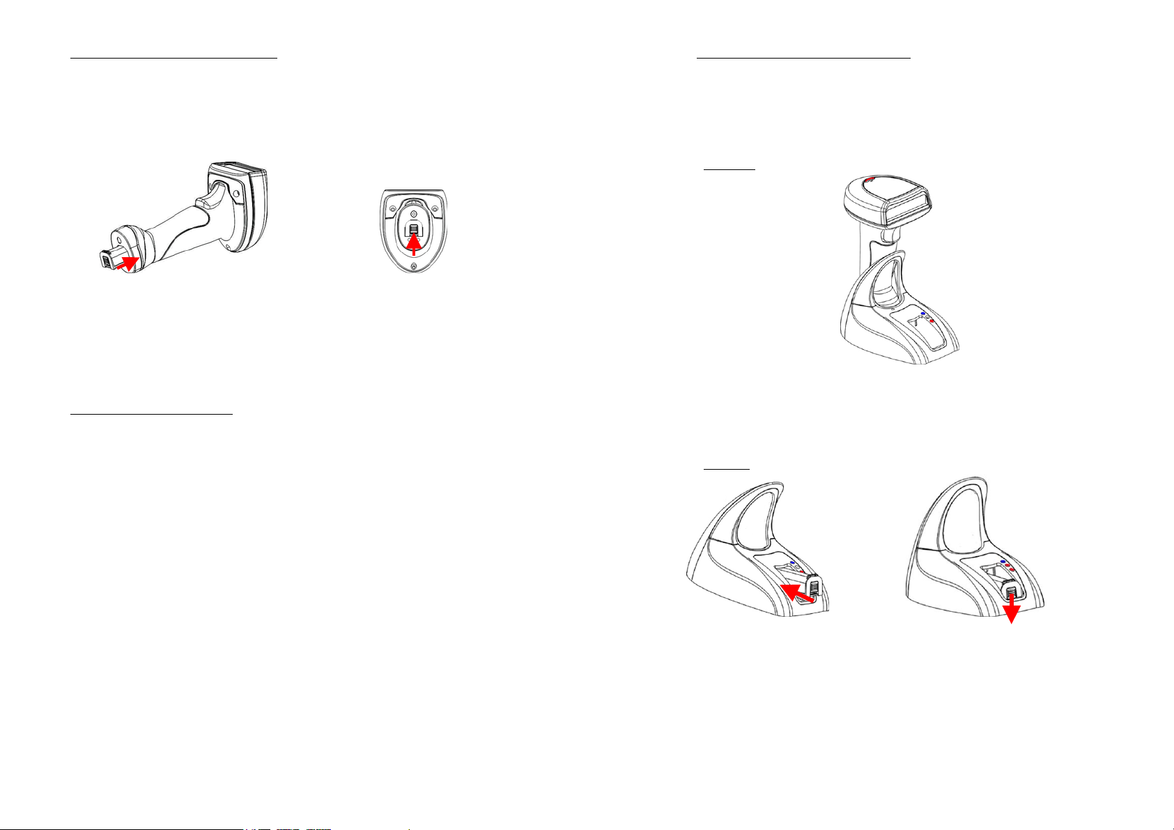
2.2 Power Up the WWS800/850
P
2.4 Charging your WWS800/850
When you receive your WWS800/850, the battery will be packaged separately.
Please insert the battery into the bottom of the scanner and lock the battery into
place by pushing up on the clip. The scanner will beep and the LED will be light
up when the device is powered on.
Please remove the battery to power off the scanner if it will not be used for a
prolonged period. The LED will be off and the power to the scanner will be
disconnected.
ush up to lock the battery.
2.3 Setup RF Connection
Upon powering up, the scanner will try to establish an RF connection with its base.
At this stage we need to “pair” the scanner and base.
Turn the base upside down and you will find 2 labels.
There are three methods to charge the battery. One is placing the scanner on the
base and another is inserting the battery in front of the base, and the other is
inserting the power supply into the DC Jack at bottom of the scanner.
2.4.1 Scanner
Place the scanner (with the battery inserted) on the base to charge your scanner.
When charging, the scanner LED will flash RED. When the battery is fully
charged, around 4 hours from completely empty battery, the LED stays on solid
RED.
2.4.2 Battery
The first label says “SET CONNECTION” and contains a barcode. The second
label is the serial number.
To link the scanner to the base, scan the “SET CONNECTION” barcode label, the
scanner will beep once then scan the SERIAL number barcode. The scanner will
beep twice, low then high. When it establishes RF connection with the base the
scanner will then emit three short ascending beeps. Your “pairing” is established.
3
Insert the battery in front of the base to charge your battery with the power adaptor
connected. When charging, the base charging LED will be RED. When the battery
is fully charged, around 4 hours from completely empty battery, the LED will be
solid GREEN.
4

3. General Features
2.4.3 DC Jack
Insert the power supply to the DC Jack at bottom of the scanner. When charging,
the scanner LED will flash RED. When the battery is fully charged, around 4 hours
from completely empty battery, the LED stays on solid RED.
2.5 Interface Setting
Once you have “paired” the scanner and base, you need to specify the interface
type to your PC. The interface settings are stored in the base. So ensure that you
have RF connection between your scanner and base prior to setting the interface
type. For details on selecting interfaces please refer to the relevant section in this
manual.
3.1 Buzzer
The buzzer of the scanner beeps differently to indicate various operating
conditions.
• Power On Beep: The scanner will issue a long beep to indicate a successful
power on.
• Good Read Beep: The system provides four volume levels and four beeping
tones (frequencies) that the user can select from to signify a good read. The
available options are:
Volume: Maximum/Loud/Medium/Minimum
Frequency: 8 / 4 / 2 / 1 kHz
• Error Beep: The scanner will issue a long beep with a low tone to indicate
errors.
• Enter / Exit Configuration Beep: The scanner will issue 6 beeps upon entering
/ exiting the configuration mode.
• Setup Beep: In configuration mode, the scanner will normally beep twice when a
setup barcode is read. If the particular setup parameter needs more than one read,
the scanner will only issue a short beep to indicate that there are more setup
barcodes needed to complete the current parameter setting.
3.2 Indicator
There is a dual color indicator on top of the scanner. Normally it is off, and will
turn red when there is a good read. The indicator will be blue when the scanner is
at configuration mode.
3.3 Scan Modes
There are eight scan modes supported by the scanner. The user can choose the
desired scan mode depending on the application requirements. But, if the scanner is
a trigger-less scanner, only continuous mode or testing mode can be selected (other
scan modes involve trigger switch interaction). The supported scan modes are
described below.
• Auto Off Mode: The scanner will start scanning once the switch is
triggered. The scanning continues until either a barcode is read or a preset
scanning period (Scanner Time-Out Duration) is expired.
6
5

• Continuous Mode: The scanner is always scanning.
• Auto Power Off Mode: The scanner will start scanning once the switch is
triggered. The scanning continues until a preset scanning period (Scanner
Time-Out Duration) is expired. Unlike the Auto Off mode, the scanner will
continue to scan and the scanning period is re-counted each time there is a
successful read.
• Alternate Mode: The scanner will start scanning once the switch is
triggered. The scanner will continue scanning until the switch is triggered
again.
• Momentary Mode: The scanner will be scanning as long as the switch is
depressed.
• Repeat Mode: The scanner is always scanning just like Continuous Mode.
But now the switch acts like a “re-transmit button”. If the switch is triggered
within 1 second after a good read, the same data will be transmitted again
without actually reading the barcode. This “re-transmit button” can be
triggered as many times as user desired, as long as the time between each
triggering does not exceed 1 second. This scan mode is most useful when
the same barcode is to be read many times.
• Laser Mode: This scan mode is used on laser scanners. The scanner will
scan once when the trigger is pressed. The scanning continues until a
barcode is read, the trigger is released or a preset scanning period (Scanner
Time-Out Duration) is expired.
• Test Mode: The scanner is always scanning. The scanner will decode
repeatedly even with the same barcode.
By default, the scan mode is Auto Off mode for scanners with trigger switch, and is
Continuous mode for switch-less scanners.
3.4 Auto-Sense
Auto-Sense is for WWS800 only and used in conjunction with the auto-sense
stand. It will enable the scanner to start scanning once a barcode is brought within
Range of the scanner. This will activate the LEDs and the scanner will start
decoding the barcode. The auto-sense mode works only under Auto Off mode or
Laser mode only.
3.5 Re-read Delay
If the scanner mode is set to Continuous, Auto Power Off, Alternate, or Momentary
mode, the scanner will prevent accidentally reading the same barcode twice by
using a Re-read Delay (Blocking Time). The barcode must be taken away from the
scanning line longer than the Re-read Delay to allow second reading of the same
barcode. The user can set the Re-read Delay if necessary.
3.6 Scanner Time-out Duration
This parameter is used to limit the maximum scanning period when the scan mode
is either Auto Off Mode or Auto Power Off Mode. This time-out duration is
specified in units of second. The default time-out duration is ten seconds.
3.7 Reading Redundancy
This parameter is used to specify the levels of reading (decoding) security. If No
Redundancy is selected, only one successful decoding can make the reading valid.
If Three Times Redundancy is selected, it will take 3 successful decodes to make
the reading valid. It is obvious that the more redundancy the user selects, the higher
the reading security and thus the slower the reading speed. The user must
compromise between decoding security and decoding speed if the security feature
is needed.
3.8 Supported Symbologies
Most of the popular barcode symbologies are supported. Each symbology can be
individually enabled or disabled. The scanner will automatically discriminate and
recognize all the symbologies that are enabled. The supported barcode symbologies
are listed below.
• Code 39 (Standard / Full ASCII)
• Italy Pharmacode
• French Pharmacode
• Industrial 25
• Interleave 25
• Matrix 25
• Codabar (NW-7)
• UPCA (with or without Addon)
• UPCE (with or without Addon)
8
7
 Loading...