

Page 1

Wasp WPS100 Projection Scanner
Product Reference Guide
Page 2

Page 3

Wasp WPS100 Projection Scanner
Product Reference Guide
Revision A
Page 4

© 2004 Wasp Technologies, Inc. All rights reserved.
Wasp Technologies, Inc.
1400 10th Street
Plano, TX 75074
http://www.waspbarcode.com
Page 5

Contents
About This Guide
Introduction . . . . . . . . . . . . . . . . . . . . . . . . . . . . . . . . . . . . . . . . . . . . . . . . . . . . . . . . . . . . . . . . . . . .xi
Chapter Descriptions . . . . . . . . . . . . . . . . . . . . . . . . . . . . . . . . . . . . . . . . . . . . . . . . . . . . . . . . . . . . .xi
Notational Conventions . . . . . . . . . . . . . . . . . . . . . . . . . . . . . . . . . . . . . . . . . . . . . . . . . . . . . . . . . . xiii
Related Publications . . . . . . . . . . . . . . . . . . . . . . . . . . . . . . . . . . . . . . . . . . . . . . . . . . . . . . . . . . . . xiii
Wasp Technical Support . . . . . . . . . . . . . . . . . . . . . . . . . . . . . . . . . . . . . . . . . . . . . . . . . . . . . . . . . xiii
Chapter 1.
Getting Started
Introduction . . . . . . . . . . . . . . . . . . . . . . . . . . . . . . . . . . . . . . . . . . . . . . . . . . . . . . . . . . . . . . . . . . 1-1
Unpacking Your Scanner. . . . . . . . . . . . . . . . . . . . . . . . . . . . . . . . . . . . . . . . . . . . . . . . . . . . . . . . 1-2
Setting Up the Scanner . . . . . . . . . . . . . . . . . . . . . . . . . . . . . . . . . . . . . . . . . . . . . . . . . . . . . . . . . 1-3
Installing the Interface Cable . . . . . . . . . . . . . . . . . . . . . . . . . . . . . . . . . . . . . . . . . . . . . . . . . 1-3
Connecting Power (if required). . . . . . . . . . . . . . . . . . . . . . . . . . . . . . . . . . . . . . . . . . . . . . . . 1-4
Configuring Your Scanner . . . . . . . . . . . . . . . . . . . . . . . . . . . . . . . . . . . . . . . . . . . . . . . . . . . 1-4
Removing the Interface Cable . . . . . . . . . . . . . . . . . . . . . . . . . . . . . . . . . . . . . . . . . . . . . . . . 1-4
Chapter 2.
Scanning
Introduction . . . . . . . . . . . . . . . . . . . . . . . . . . . . . . . . . . . . . . . . . . . . . . . . . . . . . . . . . . . . . . . . . . 2-1
Scanning in Single-Line Mode . . . . . . . . . . . . . . . . . . . . . . . . . . . . . . . . . . . . . . . . . . . . . . . . . . . . 2-2
Scanning in Omni Mode. . . . . . . . . . . . . . . . . . . . . . . . . . . . . . . . . . . . . . . . . . . . . . . . . . . . . . . . . 2-3
Beeper Definitions . . . . . . . . . . . . . . . . . . . . . . . . . . . . . . . . . . . . . . . . . . . . . . . . . . . . . . . . . . . . . 2-7
Selecting Beeper Volume using Trigger . . . . . . . . . . . . . . . . . . . . . . . . . . . . . . . . . . . . . . . . . 2-8
LED Definitions . . . . . . . . . . . . . . . . . . . . . . . . . . . . . . . . . . . . . . . . . . . . . . . . . . . . . . . . . . . . . . . 2-9
Aiming . . . . . . . . . . . . . . . . . . . . . . . . . . . . . . . . . . . . . . . . . . . . . . . . . . . . . . . . . . . . . . . . . . . . . 2-10
Decode Zone . . . . . . . . . . . . . . . . . . . . . . . . . . . . . . . . . . . . . . . . . . . . . . . . . . . . . . . . . . . . . . . . 2-11
iii
Page 6

Wasp WPS100 Product Reference Guide
Chapter 3.
Maintenance and Technical Specifications
Introduction . . . . . . . . . . . . . . . . . . . . . . . . . . . . . . . . . . . . . . . . . . . . . . . . . . . . . . . . . . . . . . . . . . . 3-1
Maintenance . . . . . . . . . . . . . . . . . . . . . . . . . . . . . . . . . . . . . . . . . . . . . . . . . . . . . . . . . . . . . . . . . . 3-1
Troubleshooting . . . . . . . . . . . . . . . . . . . . . . . . . . . . . . . . . . . . . . . . . . . . . . . . . . . . . . . . . . . . . . . 3-2
Technical Specifications . . . . . . . . . . . . . . . . . . . . . . . . . . . . . . . . . . . . . . . . . . . . . . . . . . . . . . . . . 3-4
Scanner Signal Descriptions . . . . . . . . . . . . . . . . . . . . . . . . . . . . . . . . . . . . . . . . . . . . . . . . . . . . . . 3-7
Chapter 4.
User Preferences
Introduction . . . . . . . . . . . . . . . . . . . . . . . . . . . . . . . . . . . . . . . . . . . . . . . . . . . . . . . . . . . . . . . . . . . 4-1
Scanning Sequence Examples . . . . . . . . . . . . . . . . . . . . . . . . . . . . . . . . . . . . . . . . . . . . . . . . . . . .4-2
Errors While Scanning . . . . . . . . . . . . . . . . . . . . . . . . . . . . . . . . . . . . . . . . . . . . . . . . . . . . . . . . . . 4-2
User Preferences Default Parameters . . . . . . . . . . . . . . . . . . . . . . . . . . . . . . . . . . . . . . . . . . . . . . 4-3
User Preferences . . . . . . . . . . . . . . . . . . . . . . . . . . . . . . . . . . . . . . . . . . . . . . . . . . . . . . . . . . . . . . 4-5
Set Default Parameter . . . . . . . . . . . . . . . . . . . . . . . . . . . . . . . . . . . . . . . . . . . . . . . . . . . . . . . 4-5
Beeper Tone . . . . . . . . . . . . . . . . . . . . . . . . . . . . . . . . . . . . . . . . . . . . . . . . . . . . . . . . . . . . . . 4-6
Beeper Volume . . . . . . . . . . . . . . . . . . . . . . . . . . . . . . . . . . . . . . . . . . . . . . . . . . . . . . . . . . . . 4-7
Volume Change Trigger Delay. . . . . . . . . . . . . . . . . . . . . . . . . . . . . . . . . . . . . . . . . . . . . . . . . 4-8
Laser On Time . . . . . . . . . . . . . . . . . . . . . . . . . . . . . . . . . . . . . . . . . . . . . . . . . . . . . . . . . . . . . 4-9
Beep After Good Decode. . . . . . . . . . . . . . . . . . . . . . . . . . . . . . . . . . . . . . . . . . . . . . . . . . . . 4-10
Low Power Blink . . . . . . . . . . . . . . . . . . . . . . . . . . . . . . . . . . . . . . . . . . . . . . . . . . . . . . . . . . 4-11
Scan Pattern Mode . . . . . . . . . . . . . . . . . . . . . . . . . . . . . . . . . . . . . . . . . . . . . . . . . . . . . . . .4-12
Single-Line Aim Duration . . . . . . . . . . . . . . . . . . . . . . . . . . . . . . . . . . . . . . . . . . . . . . . . . . . . 4-13
Timeout Between Decodes . . . . . . . . . . . . . . . . . . . . . . . . . . . . . . . . . . . . . . . . . . . . . . . . . . 4-15
Time Delay to Low Power Mode . . . . . . . . . . . . . . . . . . . . . . . . . . . . . . . . . . . . . . . . . . . . . . 4-16
Linear UPC/EAN Decode. . . . . . . . . . . . . . . . . . . . . . . . . . . . . . . . . . . . . . . . . . . . . . . . . . . . 4-18
Chapter 5.
Keyboard Wedge Interface
Introduction . . . . . . . . . . . . . . . . . . . . . . . . . . . . . . . . . . . . . . . . . . . . . . . . . . . . . . . . . . . . . . . . . . . 5-1
Connecting a Keyboard Wedge Interface . . . . . . . . . . . . . . . . . . . . . . . . . . . . . . . . . . . . . . . . . . . . 5-2
Keyboard Wedge Default Parameters . . . . . . . . . . . . . . . . . . . . . . . . . . . . . . . . . . . . . . . . . . . . . . 5-3
Keyboard Wedge Host Types . . . . . . . . . . . . . . . . . . . . . . . . . . . . . . . . . . . . . . . . . . . . . . . . . . . . . 5-4
Keyboard Wedge Host Types . . . . . . . . . . . . . . . . . . . . . . . . . . . . . . . . . . . . . . . . . . . . . . . . . 5-4
Keyboard Wedge Country Types (Country Codes) . . . . . . . . . . . . . . . . . . . . . . . . . . . . . . . . . 5-6
Ignore Unknown Characters . . . . . . . . . . . . . . . . . . . . . . . . . . . . . . . . . . . . . . . . . . . . . . . . . 5-10
Keystroke Delay. . . . . . . . . . . . . . . . . . . . . . . . . . . . . . . . . . . . . . . . . . . . . . . . . . . . . . . . . . . 5-11
Intra-Keystroke Delay . . . . . . . . . . . . . . . . . . . . . . . . . . . . . . . . . . . . . . . . . . . . . . . . . . . . . .5-12
Alternate Numeric Keypad Emulation . . . . . . . . . . . . . . . . . . . . . . . . . . . . . . . . . . . . . . . . . . 5-13
Caps Lock On . . . . . . . . . . . . . . . . . . . . . . . . . . . . . . . . . . . . . . . . . . . . . . . . . . . . . . . . . . . . 5-14
iv
Page 7

Contents
Caps Lock Override . . . . . . . . . . . . . . . . . . . . . . . . . . . . . . . . . . . . . . . . . . . . . . . . . . . . . . . 5-15
Convert Wedge Data . . . . . . . . . . . . . . . . . . . . . . . . . . . . . . . . . . . . . . . . . . . . . . . . . . . . . . 5-16
Function Key Mapping . . . . . . . . . . . . . . . . . . . . . . . . . . . . . . . . . . . . . . . . . . . . . . . . . . . . . 5-17
FN1 Substitution . . . . . . . . . . . . . . . . . . . . . . . . . . . . . . . . . . . . . . . . . . . . . . . . . . . . . . . . . . 5-18
Send Make Break . . . . . . . . . . . . . . . . . . . . . . . . . . . . . . . . . . . . . . . . . . . . . . . . . . . . . . . . . 5-19
Keyboard Maps . . . . . . . . . . . . . . . . . . . . . . . . . . . . . . . . . . . . . . . . . . . . . . . . . . . . . . . . . . 5-20
ASCII Character Set . . . . . . . . . . . . . . . . . . . . . . . . . . . . . . . . . . . . . . . . . . . . . . . . . . . . . . . . . . 5-23
Chapter 6.
USB Interface
Introduction . . . . . . . . . . . . . . . . . . . . . . . . . . . . . . . . . . . . . . . . . . . . . . . . . . . . . . . . . . . . . . . . . . 7-1
Connecting a USB Interface . . . . . . . . . . . . . . . . . . . . . . . . . . . . . . . . . . . . . . . . . . . . . . . . . . . . . 7-2
USB Default Parameters . . . . . . . . . . . . . . . . . . . . . . . . . . . . . . . . . . . . . . . . . . . . . . . . . . . . . . . . 7-4
USB Host Parameters . . . . . . . . . . . . . . . . . . . . . . . . . . . . . . . . . . . . . . . . . . . . . . . . . . . . . . . . . . 7-5
USB Device Type . . . . . . . . . . . . . . . . . . . . . . . . . . . . . . . . . . . . . . . . . . . . . . . . . . . . . . . . . . 7-5
USB Country Keyboard Types (Country Codes) . . . . . . . . . . . . . . . . . . . . . . . . . . . . . . . . . . 7-6
USB Keystroke Delay . . . . . . . . . . . . . . . . . . . . . . . . . . . . . . . . . . . . . . . . . . . . . . . . . . . . . . 7-10
USB CAPS Lock Override . . . . . . . . . . . . . . . . . . . . . . . . . . . . . . . . . . . . . . . . . . . . . . . . . . 7-11
USB Ignore Unknown Characters. . . . . . . . . . . . . . . . . . . . . . . . . . . . . . . . . . . . . . . . . . . . . 7-12
Emulate Keypad . . . . . . . . . . . . . . . . . . . . . . . . . . . . . . . . . . . . . . . . . . . . . . . . . . . . . . . . . . 7-13
USB Keyboard FN1 Substitution . . . . . . . . . . . . . . . . . . . . . . . . . . . . . . . . . . . . . . . . . . . . . 7-14
Function Key Mapping . . . . . . . . . . . . . . . . . . . . . . . . . . . . . . . . . . . . . . . . . . . . . . . . . . . . . 7-15
Simulated Caps Lock . . . . . . . . . . . . . . . . . . . . . . . . . . . . . . . . . . . . . . . . . . . . . . . . . . . . . . 7-16
Convert Case . . . . . . . . . . . . . . . . . . . . . . . . . . . . . . . . . . . . . . . . . . . . . . . . . . . . . . . . . . . . 7-17
ASCII Character Set . . . . . . . . . . . . . . . . . . . . . . . . . . . . . . . . . . . . . . . . . . . . . . . . . . . . . . . . . . 7-18
Chapter 7.
Symbologies
Introduction . . . . . . . . . . . . . . . . . . . . . . . . . . . . . . . . . . . . . . . . . . . . . . . . . . . . . . . . . . . . . . . . . 11-1
Scanning Sequence Examples . . . . . . . . . . . . . . . . . . . . . . . . . . . . . . . . . . . . . . . . . . . . . . . . . . 11-2
Errors While Scanning . . . . . . . . . . . . . . . . . . . . . . . . . . . . . . . . . . . . . . . . . . . . . . . . . . . . . . . . . 11-2
Symbology Default Parameters . . . . . . . . . . . . . . . . . . . . . . . . . . . . . . . . . . . . . . . . . . . . . . . . . . 11-3
UPC/EAN. . . . . . . . . . . . . . . . . . . . . . . . . . . . . . . . . . . . . . . . . . . . . . . . . . . . . . . . . . . . . . . . . . . 11-8
Enable/Disable UPC-A/UPC-E. . . . . . . . . . . . . . . . . . . . . . . . . . . . . . . . . . . . . . . . . . . . . . . 11-8
Enable/Disable UPC-E1 . . . . . . . . . . . . . . . . . . . . . . . . . . . . . . . . . . . . . . . . . . . . . . . . . . . . 11-9
Enable/Disable EAN-13/JAN-13/EAN-8/JAN-8 . . . . . . . . . . . . . . . . . . . . . . . . . . . . . . . . . 11-10
Enable/Disable Bookland EAN . . . . . . . . . . . . . . . . . . . . . . . . . . . . . . . . . . . . . . . . . . . . . . 11-11
Decode UPC/EAN Supplementals . . . . . . . . . . . . . . . . . . . . . . . . . . . . . . . . . . . . . . . . . . . 11-12
UPC/EAN Supplemental Redundancy . . . . . . . . . . . . . . . . . . . . . . . . . . . . . . . . . . . . . . . . 11-15
Transmit UPC-A/UPC-E/UPC-E1 Check Digit . . . . . . . . . . . . . . . . . . . . . . . . . . . . . . . . . . 11-16
UPC-A Preamble . . . . . . . . . . . . . . . . . . . . . . . . . . . . . . . . . . . . . . . . . . . . . . . . . . . . . . . . 11-18
UPC-E Preamble . . . . . . . . . . . . . . . . . . . . . . . . . . . . . . . . . . . . . . . . . . . . . . . . . . . . . . . . 11-19
v
Page 8

Wasp WPS100 Product Reference Guide
UPC-E1 Preamble . . . . . . . . . . . . . . . . . . . . . . . . . . . . . . . . . . . . . . . . . . . . . . . . . . . . . . . . 11-20
Convert UPC-E to UPC-A . . . . . . . . . . . . . . . . . . . . . . . . . . . . . . . . . . . . . . . . . . . . . . . . . . 11-21
Convert UPC-E1 to UPC-A . . . . . . . . . . . . . . . . . . . . . . . . . . . . . . . . . . . . . . . . . . . . . . . . . 11-22
EAN Zero Extend. . . . . . . . . . . . . . . . . . . . . . . . . . . . . . . . . . . . . . . . . . . . . . . . . . . . . . . . . 11-23
UCC Coupon Extended Code . . . . . . . . . . . . . . . . . . . . . . . . . . . . . . . . . . . . . . . . . . . . . . . 11-24
Code 128 . . . . . . . . . . . . . . . . . . . . . . . . . . . . . . . . . . . . . . . . . . . . . . . . . . . . . . . . . . . . . . . . . . 11-25
Enable/Disable Code 128 . . . . . . . . . . . . . . . . . . . . . . . . . . . . . . . . . . . . . . . . . . . . . . . . . . 11-25
Enable/Disable UCC/EAN-128 . . . . . . . . . . . . . . . . . . . . . . . . . . . . . . . . . . . . . . . . . . . . . . 11-26
Enable/Disable ISBT 128. . . . . . . . . . . . . . . . . . . . . . . . . . . . . . . . . . . . . . . . . . . . . . . . . . . 11-27
Code 128 Decode Performance . . . . . . . . . . . . . . . . . . . . . . . . . . . . . . . . . . . . . . . . . . . . . 11-28
Code 128 Decode Performance Level. . . . . . . . . . . . . . . . . . . . . . . . . . . . . . . . . . . . . . . . . 11-29
Code 39 . . . . . . . . . . . . . . . . . . . . . . . . . . . . . . . . . . . . . . . . . . . . . . . . . . . . . . . . . . . . . . . . . . . 11-30
Enable/Disable Code 39 . . . . . . . . . . . . . . . . . . . . . . . . . . . . . . . . . . . . . . . . . . . . . . . . . . . 11-30
Enable/Disable Trioptic Code 39 . . . . . . . . . . . . . . . . . . . . . . . . . . . . . . . . . . . . . . . . . . . . . 11-31
Convert Code 39 to Code 32 . . . . . . . . . . . . . . . . . . . . . . . . . . . . . . . . . . . . . . . . . . . . . . . . 11-32
Code 32 Prefix . . . . . . . . . . . . . . . . . . . . . . . . . . . . . . . . . . . . . . . . . . . . . . . . . . . . . . . . . . . 11-33
Set Lengths for Code 39 . . . . . . . . . . . . . . . . . . . . . . . . . . . . . . . . . . . . . . . . . . . . . . . . . . . 11-34
Code 39 Check Digit Verification . . . . . . . . . . . . . . . . . . . . . . . . . . . . . . . . . . . . . . . . . . . . . 11-36
Transmit Code 39 Check Digit. . . . . . . . . . . . . . . . . . . . . . . . . . . . . . . . . . . . . . . . . . . . . . . 11-37
Enable/Disable Code 39 Full ASCII . . . . . . . . . . . . . . . . . . . . . . . . . . . . . . . . . . . . . . . . . . . 11-38
Code 39 Buffering (Scan & Store) . . . . . . . . . . . . . . . . . . . . . . . . . . . . . . . . . . . . . . . . . . . . 11-39
Code 39 Decode Performance . . . . . . . . . . . . . . . . . . . . . . . . . . . . . . . . . . . . . . . . . . . . . . 11-43
Code 39 Decode Performance Level. . . . . . . . . . . . . . . . . . . . . . . . . . . . . . . . . . . . . . . . . . 11-44
Code 93 . . . . . . . . . . . . . . . . . . . . . . . . . . . . . . . . . . . . . . . . . . . . . . . . . . . . . . . . . . . . . . . . . . . 11-45
Enable/Disable Code 93 . . . . . . . . . . . . . . . . . . . . . . . . . . . . . . . . . . . . . . . . . . . . . . . . . . . 11-45
Set Lengths for Code 93 . . . . . . . . . . . . . . . . . . . . . . . . . . . . . . . . . . . . . . . . . . . . . . . . . . . 11-46
Code 11 . . . . . . . . . . . . . . . . . . . . . . . . . . . . . . . . . . . . . . . . . . . . . . . . . . . . . . . . . . . . . . . . . . . 11-48
Code 11 . . . . . . . . . . . . . . . . . . . . . . . . . . . . . . . . . . . . . . . . . . . . . . . . . . . . . . . . . . . . . . . . 11-48
Set Lengths for Code 11 . . . . . . . . . . . . . . . . . . . . . . . . . . . . . . . . . . . . . . . . . . . . . . . . . . . 11-49
Code 11 Check Digit Verification . . . . . . . . . . . . . . . . . . . . . . . . . . . . . . . . . . . . . . . . . . . . . 11-51
Transmit Code 11 Check Digits . . . . . . . . . . . . . . . . . . . . . . . . . . . . . . . . . . . . . . . . . . . . . . 11-52
Interleaved 2 of 5 (ITF) . . . . . . . . . . . . . . . . . . . . . . . . . . . . . . . . . . . . . . . . . . . . . . . . . . . . . . . . 11-53
Enable/Disable Interleaved 2 of 5 . . . . . . . . . . . . . . . . . . . . . . . . . . . . . . . . . . . . . . . . . . . . 11-53
Set Lengths for Interleaved 2 of 5 . . . . . . . . . . . . . . . . . . . . . . . . . . . . . . . . . . . . . . . . . . . . 11-54
I 2 of 5 Check Digit Verification . . . . . . . . . . . . . . . . . . . . . . . . . . . . . . . . . . . . . . . . . . . . . . 11-56
Transmit I 2 of 5 Check Digit . . . . . . . . . . . . . . . . . . . . . . . . . . . . . . . . . . . . . . . . . . . . . . . . 11-57
Convert I 2 of 5 to EAN-13. . . . . . . . . . . . . . . . . . . . . . . . . . . . . . . . . . . . . . . . . . . . . . . . . . 11-58
Discrete 2 of 5 (DTF). . . . . . . . . . . . . . . . . . . . . . . . . . . . . . . . . . . . . . . . . . . . . . . . . . . . . . . . . . 11-59
Enable/Disable Discrete 2 of 5. . . . . . . . . . . . . . . . . . . . . . . . . . . . . . . . . . . . . . . . . . . . . . . 11-59
Set Lengths for Discrete 2 of 5 . . . . . . . . . . . . . . . . . . . . . . . . . . . . . . . . . . . . . . . . . . . . . . 11-60
Chinese 2 of 5. . . . . . . . . . . . . . . . . . . . . . . . . . . . . . . . . . . . . . . . . . . . . . . . . . . . . . . . . . . . . . . 11-62
Enable/Disable Chinese 2 of 5. . . . . . . . . . . . . . . . . . . . . . . . . . . . . . . . . . . . . . . . . . . . . . . 11-62
Codabar (NW - 7) . . . . . . . . . . . . . . . . . . . . . . . . . . . . . . . . . . . . . . . . . . . . . . . . . . . . . . . . . . . . 11-63
Enable/Disable Codabar . . . . . . . . . . . . . . . . . . . . . . . . . . . . . . . . . . . . . . . . . . . . . . . . . . . 11-63
vi
Page 9

Contents
Set Lengths for Codabar . . . . . . . . . . . . . . . . . . . . . . . . . . . . . . . . . . . . . . . . . . . . . . . . . . 11-64
CLSI Editing . . . . . . . . . . . . . . . . . . . . . . . . . . . . . . . . . . . . . . . . . . . . . . . . . . . . . . . . . . . . 11-66
NOTIS Editing. . . . . . . . . . . . . . . . . . . . . . . . . . . . . . . . . . . . . . . . . . . . . . . . . . . . . . . . . . . 11-67
MSI . . . . . . . . . . . . . . . . . . . . . . . . . . . . . . . . . . . . . . . . . . . . . . . . . . . . . . . . . . . . . . . . . . . . . . 11-68
Enable/Disable MSI . . . . . . . . . . . . . . . . . . . . . . . . . . . . . . . . . . . . . . . . . . . . . . . . . . . . . . 11-68
Set Lengths for MSI . . . . . . . . . . . . . . . . . . . . . . . . . . . . . . . . . . . . . . . . . . . . . . . . . . . . . . 11-69
MSI Check Digits . . . . . . . . . . . . . . . . . . . . . . . . . . . . . . . . . . . . . . . . . . . . . . . . . . . . . . . . 11-71
Transmit MSI Check Digit(s). . . . . . . . . . . . . . . . . . . . . . . . . . . . . . . . . . . . . . . . . . . . . . . . 11-72
MSI Check Digit Algorithm . . . . . . . . . . . . . . . . . . . . . . . . . . . . . . . . . . . . . . . . . . . . . . . . . 11-73
RSS (Reduced Space Symbology) . . . . . . . . . . . . . . . . . . . . . . . . . . . . . . . . . . . . . . . . . . . . . . 11-74
RSS 14 . . . . . . . . . . . . . . . . . . . . . . . . . . . . . . . . . . . . . . . . . . . . . . . . . . . . . . . . . . . . . . . . 11-74
RSS Limited . . . . . . . . . . . . . . . . . . . . . . . . . . . . . . . . . . . . . . . . . . . . . . . . . . . . . . . . . . . . 11-75
RSS Expanded . . . . . . . . . . . . . . . . . . . . . . . . . . . . . . . . . . . . . . . . . . . . . . . . . . . . . . . . . . 11-76
Convert RSS to UPC/EAN . . . . . . . . . . . . . . . . . . . . . . . . . . . . . . . . . . . . . . . . . . . . . . . . . 11-77
Symbology - Specific Security Levels . . . . . . . . . . . . . . . . . . . . . . . . . . . . . . . . . . . . . . . . . . . . 11-80
Redundancy Level . . . . . . . . . . . . . . . . . . . . . . . . . . . . . . . . . . . . . . . . . . . . . . . . . . . . . . . 11-80
Security Level . . . . . . . . . . . . . . . . . . . . . . . . . . . . . . . . . . . . . . . . . . . . . . . . . . . . . . . . . . . 11-83
Symbology - Intercharacter Gap . . . . . . . . . . . . . . . . . . . . . . . . . . . . . . . . . . . . . . . . . . . . . . . . 11-85
Chapter 8.
Miscellaneous Scanner Options
Introduction . . . . . . . . . . . . . . . . . . . . . . . . . . . . . . . . . . . . . . . . . . . . . . . . . . . . . . . . . . . . . . . . . 12-1
Scanning Sequence Examples . . . . . . . . . . . . . . . . . . . . . . . . . . . . . . . . . . . . . . . . . . . . . . . . . . 12-2
Errors While Scanning . . . . . . . . . . . . . . . . . . . . . . . . . . . . . . . . . . . . . . . . . . . . . . . . . . . . . . . . . 12-2
Miscellaneous Default Parameters . . . . . . . . . . . . . . . . . . . . . . . . . . . . . . . . . . . . . . . . . . . . . . . 12-3
Miscellaneous Scanner Parameters . . . . . . . . . . . . . . . . . . . . . . . . . . . . . . . . . . . . . . . . . . . . . . 12-4
Transmit Code ID Character. . . . . . . . . . . . . . . . . . . . . . . . . . . . . . . . . . . . . . . . . . . . . . . . . 12-4
Prefix/Suffix Values . . . . . . . . . . . . . . . . . . . . . . . . . . . . . . . . . . . . . . . . . . . . . . . . . . . . . . . 12-5
FN1 Substitution Values . . . . . . . . . . . . . . . . . . . . . . . . . . . . . . . . . . . . . . . . . . . . . . . . . . . . 12-8
Scan Data Options . . . . . . . . . . . . . . . . . . . . . . . . . . . . . . . . . . . . . . . . . . . . . . . . . . . . . . . . 12-9
Transmit “No Read” Message. . . . . . . . . . . . . . . . . . . . . . . . . . . . . . . . . . . . . . . . . . . . . . . 12-12
Chapter 9.
Advanced Data Formatting
Introduction . . . . . . . . . . . . . . . . . . . . . . . . . . . . . . . . . . . . . . . . . . . . . . . . . . . . . . . . . . . . . . . . . 13-1
Using ADF Bar Codes . . . . . . . . . . . . . . . . . . . . . . . . . . . . . . . . . . . . . . . . . . . . . . . . . . . . . . . . . 13-2
ADF Bar Code Menu Example. . . . . . . . . . . . . . . . . . . . . . . . . . . . . . . . . . . . . . . . . . . . . . . . . . . 13-2
Rule 1: The Code 128 Scanning Rule . . . . . . . . . . . . . . . . . . . . . . . . . . . . . . . . . . . . . . . . . 13-3
Rule 2: The UPC Scanning Rule . . . . . . . . . . . . . . . . . . . . . . . . . . . . . . . . . . . . . . . . . . . . . 13-3
Alternate Rule Sets. . . . . . . . . . . . . . . . . . . . . . . . . . . . . . . . . . . . . . . . . . . . . . . . . . . . . . . . 13-4
Rules Hierarchy (in Bar Codes) . . . . . . . . . . . . . . . . . . . . . . . . . . . . . . . . . . . . . . . . . . . . . . 13-5
Default Rules . . . . . . . . . . . . . . . . . . . . . . . . . . . . . . . . . . . . . . . . . . . . . . . . . . . . . . . . . . . . 13-6
vii
Page 10

Wasp WPS100 Product Reference Guide
Special Commands. . . . . . . . . . . . . . . . . . . . . . . . . . . . . . . . . . . . . . . . . . . . . . . . . . . . . . . . . . . .13-7
Pause Duration . . . . . . . . . . . . . . . . . . . . . . . . . . . . . . . . . . . . . . . . . . . . . . . . . . . . . . . . . . . 13-7
Begin New Rule . . . . . . . . . . . . . . . . . . . . . . . . . . . . . . . . . . . . . . . . . . . . . . . . . . . . . . . . . . . 13-7
Save Rule . . . . . . . . . . . . . . . . . . . . . . . . . . . . . . . . . . . . . . . . . . . . . . . . . . . . . . . . . . . . . . . 13-8
Erase . . . . . . . . . . . . . . . . . . . . . . . . . . . . . . . . . . . . . . . . . . . . . . . . . . . . . . . . . . . . . . . . . . . 13-8
Quit Entering Rules . . . . . . . . . . . . . . . . . . . . . . . . . . . . . . . . . . . . . . . . . . . . . . . . . . . . . . . . 13-9
Disable Rule Set . . . . . . . . . . . . . . . . . . . . . . . . . . . . . . . . . . . . . . . . . . . . . . . . . . . . . . . . . 13-10
Criteria. . . . . . . . . . . . . . . . . . . . . . . . . . . . . . . . . . . . . . . . . . . . . . . . . . . . . . . . . . . . . . . . . . . . . 13-12
Code Types . . . . . . . . . . . . . . . . . . . . . . . . . . . . . . . . . . . . . . . . . . . . . . . . . . . . . . . . . . . . . 13-12
Code Lengths . . . . . . . . . . . . . . . . . . . . . . . . . . . . . . . . . . . . . . . . . . . . . . . . . . . . . . . . . . . 13-20
Message Containing A Specific Data String . . . . . . . . . . . . . . . . . . . . . . . . . . . . . . . . . . . . 13-30
Actions . . . . . . . . . . . . . . . . . . . . . . . . . . . . . . . . . . . . . . . . . . . . . . . . . . . . . . . . . . . . . . . . . . . . 13-34
Send Data . . . . . . . . . . . . . . . . . . . . . . . . . . . . . . . . . . . . . . . . . . . . . . . . . . . . . . . . . . . . . . 13-34
Setup Field(s) . . . . . . . . . . . . . . . . . . . . . . . . . . . . . . . . . . . . . . . . . . . . . . . . . . . . . . . . . . . 13-42
Modify Data . . . . . . . . . . . . . . . . . . . . . . . . . . . . . . . . . . . . . . . . . . . . . . . . . . . . . . . . . . . . . 13-53
Pad Data with Zeros . . . . . . . . . . . . . . . . . . . . . . . . . . . . . . . . . . . . . . . . . . . . . . . . . . . . . . 13-66
Beeps. . . . . . . . . . . . . . . . . . . . . . . . . . . . . . . . . . . . . . . . . . . . . . . . . . . . . . . . . . . . . . . . . . 13-76
Send Keystroke (Control Characters and Keyboard Characters) . . . . . . . . . . . . . . . . . . . . 13-77
Send Right Control Key . . . . . . . . . . . . . . . . . . . . . . . . . . . . . . . . . . . . . . . . . . . . . . . . . . . 13-162
Send Graphic User Interface Characters. . . . . . . . . . . . . . . . . . . . . . . . . . . . . . . . . . . . . . 13-163
Turn On/Off Rule Sets . . . . . . . . . . . . . . . . . . . . . . . . . . . . . . . . . . . . . . . . . . . . . . . . . . . . 13-175
Alphanumeric Keyboard . . . . . . . . . . . . . . . . . . . . . . . . . . . . . . . . . . . . . . . . . . . . . . . . . . . . . . 13-178
Appendix A.
Standard Default Parameters
Appendix B.
Programming Reference
Symbol Code Identifiers . . . . . . . . . . . . . . . . . . . . . . . . . . . . . . . . . . . . . . . . . . . . . . . . . . . . . . . . .B-1
AIM Code Identifiers . . . . . . . . . . . . . . . . . . . . . . . . . . . . . . . . . . . . . . . . . . . . . . . . . . . . . . . . . . . .B-3
Appendix C.
Sample Bar Codes
Code 39 . . . . . . . . . . . . . . . . . . . . . . . . . . . . . . . . . . . . . . . . . . . . . . . . . . . . . . . . . . . . . . . . . . . . .C-1
UPC/EAN . . . . . . . . . . . . . . . . . . . . . . . . . . . . . . . . . . . . . . . . . . . . . . . . . . . . . . . . . . . . . . . . . . . .C-1
UPC-A, 100 % . . . . . . . . . . . . . . . . . . . . . . . . . . . . . . . . . . . . . . . . . . . . . . . . . . . . . . . . . . . . .C-1
EAN-13, 100 % . . . . . . . . . . . . . . . . . . . . . . . . . . . . . . . . . . . . . . . . . . . . . . . . . . . . . . . . . . . .C-2
Code 128 . . . . . . . . . . . . . . . . . . . . . . . . . . . . . . . . . . . . . . . . . . . . . . . . . . . . . . . . . . . . . . . . . . . .C-2
Interleaved 2 of 5 . . . . . . . . . . . . . . . . . . . . . . . . . . . . . . . . . . . . . . . . . . . . . . . . . . . . . . . . . . . . . .C-2
RSS 14 . . . . . . . . . . . . . . . . . . . . . . . . . . . . . . . . . . . . . . . . . . . . . . . . . . . . . . . . . . . . . . . . . . . . . .C-3
viii
Page 11

Contents
Appendix D.
Numeric Bar Codes
0, 1. . . . . . . . . . . . . . . . . . . . . . . . . . . . . . . . . . . . . . . . . . . . . . . . . . . . . . . . . . . . . . . . . . . . . . . . . D-1
2, 3, 4. . . . . . . . . . . . . . . . . . . . . . . . . . . . . . . . . . . . . . . . . . . . . . . . . . . . . . . . . . . . . . . . . . . . . . . D-2
5, 6, 7. . . . . . . . . . . . . . . . . . . . . . . . . . . . . . . . . . . . . . . . . . . . . . . . . . . . . . . . . . . . . . . . . . . . . . . D-3
8, 9. . . . . . . . . . . . . . . . . . . . . . . . . . . . . . . . . . . . . . . . . . . . . . . . . . . . . . . . . . . . . . . . . . . . . . . . . D-4
Cancel . . . . . . . . . . . . . . . . . . . . . . . . . . . . . . . . . . . . . . . . . . . . . . . . . . . . . . . . . . . . . . . . . . . . . . D-5
Glossary
Index
ix
Page 12

Wasp WPS100 Product Reference Guide
x
Page 13

About This Guide
Introduction
The Wasp WPS100 Product Reference Guide provides general instructions for setting up,
operating, maintaining and troubleshooting the WPS100 scanner.
Chapter Descriptions
• Chapter 1, Getting Started provides a product overview and unpacking
instructions.
• Chapter 2, Scanning describes parts of the scanner, beeper and LED definitions,
how to use the scanner in hand-held and hands-free modes.
• Chapter 3, Maintenance and Technical Specifications provides information on how
to care for your scanner, troubleshooting, and technical specifications.
• Chapter 4, User Preferences provides the programming bar codes necessary for
selecting user preference features for your scanner.
• Chapter 5, Keyboard Wedge Interface covers information for setting up your
scanner for Keyboard Wedge operation.
• Chapter 6, USB Interface covers information for setting up your scanner for USB
operation.
• Chapter 7, Symbologies describes all symbology features and provides the
programming bar codes necessary for selecting these features for your scanner.
• Chapter 8, Miscellaneous Scanner Options includes commonly used bar codes to
customize how your data is transmitted to your host device.
• Chapter 9, Advanced Data Formatting (ADF) describes how to customize scanned
data before transmitting to the host.
xi
Page 14

Wasp WPS100 Product Reference Guide
• Appendix A, Standard Default Parameters provides a table of all host devices and
miscellaneous scanner defaults.
• Appendix B, Programming Reference provides a table of AIM code identifiers,
ASCII character conversions, and keyboard maps.
• Appendix C, Sample Bar Codes includes sample bar codes.
• Appendix D, Numeric Bar Codes includes the numeric bar codes to scan for
parameters requiring specific numeric values.
xii
Page 15

About This Guide
Notational Conventions
The following conventions are used in this document:
• Bullets (•) indicate:
• action items
• lists of alternatives
• lists of required steps that are not necessarily sequential
• Sequential lists (e.g., those that describe step-by-step procedures) appear as
numbered lists.
• Throughout the programming bar code menus, asterisks (*) are used to denote
default parameter settings.
* Indicates Default
*Baud Rate 9600
Feature/Option
Related Publications
The Wasp WPS100 Quick Reference Guide, provides general information to help the user
get started with the scanner. It includes basic set-up and operation instructions.
For the latest versions of the WPS100 Quick Reference Guide and Product Reference
Guide go to: http://support.waspbarcode.com.
Wasp Technical Support
If you have a problem with your equipment, Submit a Ticket at:
http://support.waspbarcode.com.
xiii
Page 16

Wasp WPS100 Product Reference Guide
xiv
Page 17
Chapter 1
Getting Started
Introduction
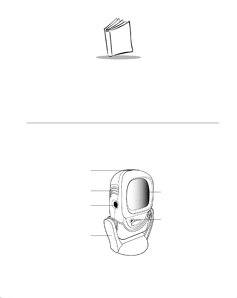
The WPS100 projection scanner provides multiple scan pattern capabilities that support
various applications at the POS (point of sale). For fast, intuitive, hands-free scanning, use
the rastering, 100-line, omni-directional scan pattern. To read bar code menus and pick
lists, use the Single-Scan line. The scanner can also be picked up to scan heavy or bulky
merchandise. The scanner reads all retail symbologies and has multi-interface capability to
allow it to interface to all popular POS devices..
Decode
LED
Finger Grips
Single Scan
Line Trigger
and Volume
Control
Hands-Free
Adjustable
Stand
Exit Window
Beeper
Figure 1-1. WPS100 Scanner
1-1
Page 18

Wasp WPS100 Product Reference Guide
The WPS100 scanner supports the following interfaces:
• Keyboard Wedge connection to a host. Scanned data is interpreted by your host
as keystrokes.
• International Keyboards supported (for Windows
American, German, French, Spanish, Italian, Swedish, UK English, Brazilian/
Portuguese and Japanese.
• International Keyboards supported (for Win XP/2000
Canadian
• International Keyboards supported (for Win 95/98 environment):French
Canadian
• USB connection to a host. The scanner autodetects a USB host and defaults to the
HID keyboard interface type. Other USB interface types are selectable by scanning
programming bar code menus.
• International Keyboards supported (for Windows
America, German, French, French International, Spanish, Italian, Swedish,
British, and Japanese.
™ environment): North
™ environment):French
™ environment): North
Unpacking Your Scanner
Remove the scanner from its packing and inspect it for damage. KEEP THE PACKING. It
is the approved shipping container and should be used if you ever need to return your
equipment for servicing.
1-2
Page 19
Getting Started
Setting Up the Scanner
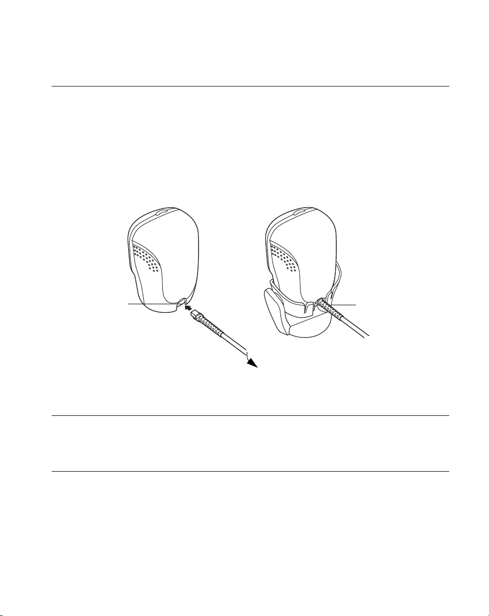
Installing the Interface Cable
1. Connect the interface cable to the host computer.
2. Plug the interface cable modular connector into the interface cable port on the rear
of the WPS100 (See Figure 1-2.)
3. Push the connector into the housing until a “click” sound is heard. The green LED
lights up and three short high beeps sound, indicating that the scanner is
operational..
Cable interface
port
To host
Interface cable
modular connector
Figure 1-2. Installing the Interface Cable
Note: Different cables are required for different hosts. The connectors
illustrated in each host chapter are examples only. Your connectors
may be different than those illustrated, but the steps to connect your
scanner remain the same.
1-3
Page 20

Wasp WPS100 Product Reference Guide
Connecting Power (if required)
If your host does not provide power to the scanner, you will need an external power
connection to the scanner:
1. Connect the interface cable to the back of the scanner, as described in Installing
the Interface Cable on page 1-3.
2. Connect the other end of the interface cable to the host (refer to your host manual
to locate the correct port).
3. Plug the power supply into the power jack on the interface cable.
4. Plug the other end of the power supply into an AC outlet.
Configuring Your Scanner
Configure your scanner using the bar codes included in this manual. Refer to Chapter 4,
User Preferences for information about programming your scanner using bar code menus.
The scanner supports Keyboard Wedge and USB interfaces. Each host specific chapter
describes how to set up each of these connections.
Removing the Interface Cable
To remove the interface cable:
1. Unplug the installed cable’s modular connector by depressing the connector clip
and gently pulling back.
2. Follow the steps for Installing the Interface Cable on page 1-3 to connect a new
cable.
1-4
Page 21
Chapter 2
Scanning
Introduction
This chapter covers the techniques involved in scanning bar codes, beeper and LED
definitions, and general instructions and tips about scanning.
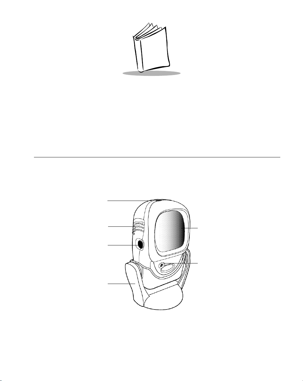
Decode
LED
Finger Grips
Single Scan
Line Trigger
and Volume
Control
Hands-Free
Adjustable
Stand
Exit Window
Beeper
Figure 2-1. WPS100 Scanner Parts
2-1
Page 22
Wasp WPS100 Product Reference Guide
Scanning in Single-Line Mode
Install and program your scanner. (Refer to each host chapter and Chapter 4, User
Preferences, Chapter 7, Symbologies, Chapter 8, Miscellaneous Scanner Options, and
Chapter 9, Advanced Data Formatting for instructions on programming your scanner.) If
you need assistance, contact Wasp Technical Support at http://support.waspbarcode.com.
1. Ensure all connections are secure. (Refer to the host chapter for your scanner.)
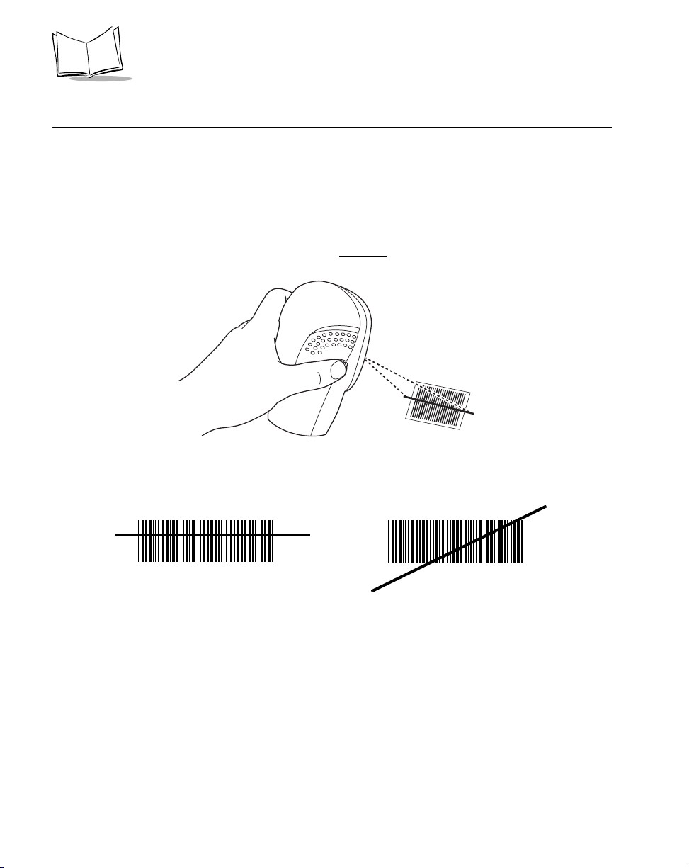
2. Pick up the scanner. Press and then release
displays.
Figure 2-2. Scanning in Hand-Held Mode
the trigger. A single scan line
3. Ensure the scan line crosses every bar and space of the symbol.
RIGHT
012345
4. Depress and hold the trigger until either:
a. The scanner reads the bar code. The scanner beeps, the LED flashes and the
laser turns off.
b. The scanner does not read the barcode and the laser turns off.
5. Release the trigger. This causes the aim scan line to reappear. To read another
bar code in single-line mode, repeat steps 2, 3 and 4. This step can be repeated
as often as desired.
6. After a programmable time period, the omni-directional scan pattern displays. This
indicates the scanner is ready to read bar codes without use of the trigger.
7. For more information on beeper definitions, refer to Table 2-1.
2-2
WRONG
012345
Page 23

Scanning
Scanning in Omni Mode
In this mode, an omni scan pattern provides rapid, orientation-free scanning. This scan
pattern is used with either hands-free or hand-held scanning
To scan a bar code, direct it in toward the window of the scanner (“presentation” scanning,
see Figure 2-7 on page 2-6) or from side to side in a sweeping motion (“swipe” scanning,
see Figure 2-8 on page 2-6).
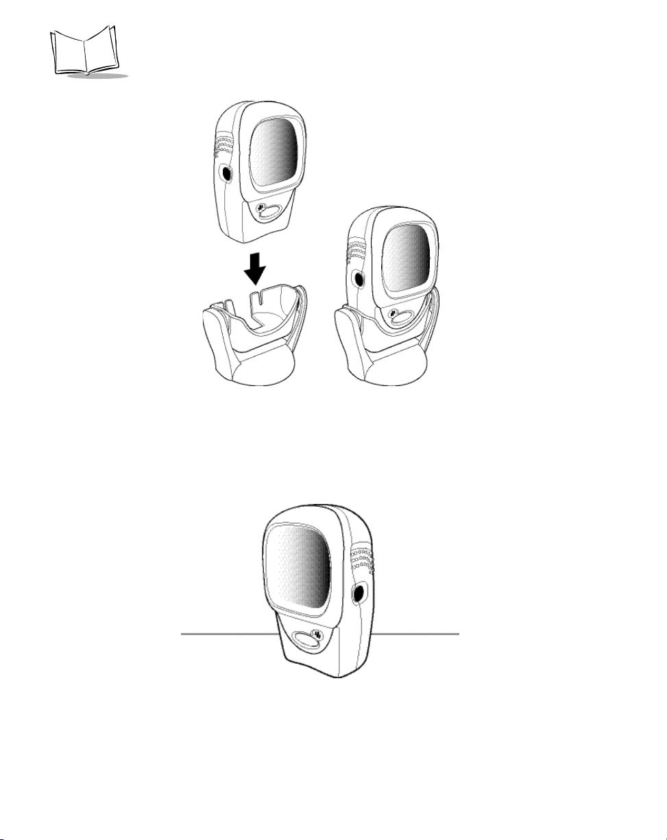
1. Ensure all cable connections are secure.
2. Insert the scanner in the optional hands-free stand by placing the front of the
scanner into the stand’s “cradle” (see Figure 2-3) or place the scanner on a flat
surface (see Figure 2-4).
3. To scan a bar code, present the bar code and ensure the scan lines cross every
bar and space of the symbol. The scan pattern becomes steady when the scanner
detects the bar code. See Figure 2-5 on page 2-5 for scanning in hands-free mode
and Figure 2-6 on page 2-5 for scanning in hand-held mode.
4. Upon successful decode, the scanner beeps and the green LED flashes
momentarily.
..
2-3
Page 24
Wasp WPS100 Product Reference Guide
Figure 2-3. Scanner in the Stand
2-4
Figure 2-4. Scanner Standing Alone
Page 25
Scanning
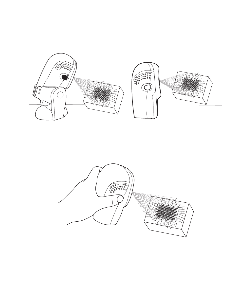
A rastering, 100-line, omni-directional scan pattern provides rapid, orientation-free
scanning. This scan pattern can be used in either hands-free or hand-held mode.
(with stand)
(on table-top)
Figure 2-5. Hands-Free Mode
Figure 2-6. Hand-Held Mode
2-5
Page 26
Wasp WPS100 Product Reference Guide
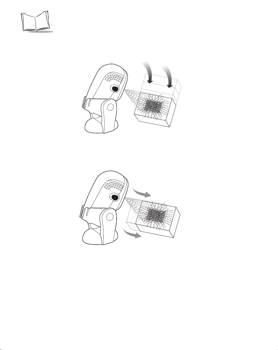
To scan a bar code, present it to the exit window of the scanner (“presentation” scanning)
or move it from side-to-side in a sweeping motion (“swipe” scanning) as show below:
Figure 2-7. “Presentation” scanning
2-6
Figure 2-8. “Swipe” scanning
Page 27

Scanning
Beeper Definitions
The scanner communicates with the user by emitting different beeper sequences and
patterns. Table 2-1 defines beep sequences that occur during both normal scanning and
while programming the scanner.
Table 2-1. Standard Beeper Definitions
Beeper Sequence Indication
Standard Use
3 short high beeps Power up.
Short high beep A bar code symbol was decoded (if decode beeper
is enabled).
4 long low beeps A transmission error was detected in a scanned
symbol. The data is ignored. This occurs if a unit is
not properly configured. Check option setting.
5 low beeps Conversion or format error.
Lo/hi/lo beep Transmit error.
Hi/hi/hi/lo beep Receive error.
Parameter Menu Scanning
Short high beep Correct entry scanned or correct menu sequence
performed.
Lo/hi beep Input error, incorrect bar code or “Cancel” scanned,
wrong entry, incorrect bar code programming
sequence; remain in program mode.
Hi/lo beep Keyboard parameter selected. Enter value using
bar code keypad.
Hi/lo/hi/lo beep Successful program exit with change in the
parameter setting.
Low/hi/low/hi beep Out of host parameter storage space. Scan Set
Default Parameter on page 4-5.
Code 39 Buffering
Hi/lo beep New Code 39 data was entered into the buffer.
3 long high beeps Code 39 buffer is full.
2-7
Page 28

Wasp WPS100 Product Reference Guide
Table 2-1. Standard Beeper Definitions
Beeper Sequence Indication
Lo/hi/lo beep The Code 39 buffer was erased or there was an
attempt to clear or transmit an empty buffer.
Lo/hi beep A successful transmission of buffered data.
Host Specific
USB only
4 short high beeps Scanner has not completed initialization. Wait
several seconds and scan again.
Scanner gives a power-up
beep after scanning a USB
Device Type.
This power-up beep occurs
more than once.
Communication with the bus must be established
before the scanner can operate at the highest
power level.
The USB bus may put the scanner in a state where
power to the scanner is cycled on and off more than
once. This is normal and usually happens when the
PC cold boots.
Selecting Beeper Volume using Trigger
The scanner emits a short beep when it successfully reads a bar code. The volume of the
beep can be changed either by scanning the appropriate bar code in Beeper Volume on
page 4-7, or by utilizing the trigger as follows:
1. Press and hold the trigger for an extended period of time (approximately 5
seconds). The scanner cycles through three settings (Low, Medium, High) emitting
a 2-beep tone at each setting.
2. To select a particular setting, release the trigger after the desired 2-beep tone is
heard.
2-8
Page 29

Scanning
LED Definitions
In addition to beeper sequences, the scanner communicates with the user using an LED
display. Table 2-2 defines LED flashes that display during scanning.
Table 2-2. Standard LED Definitions
LED Indication
Off No power is applied to the scanner.
Green The scanner is on and “ready to scan.”
Momentary flash A bar code was successfully decoded.
Slow continuous flashing The scanner is in programming mode.
Fast continuous flashing There is a internal problem; the laser is shut off for
regulatory reasons.
2-9
Page 30
Wasp WPS100 Product Reference Guide
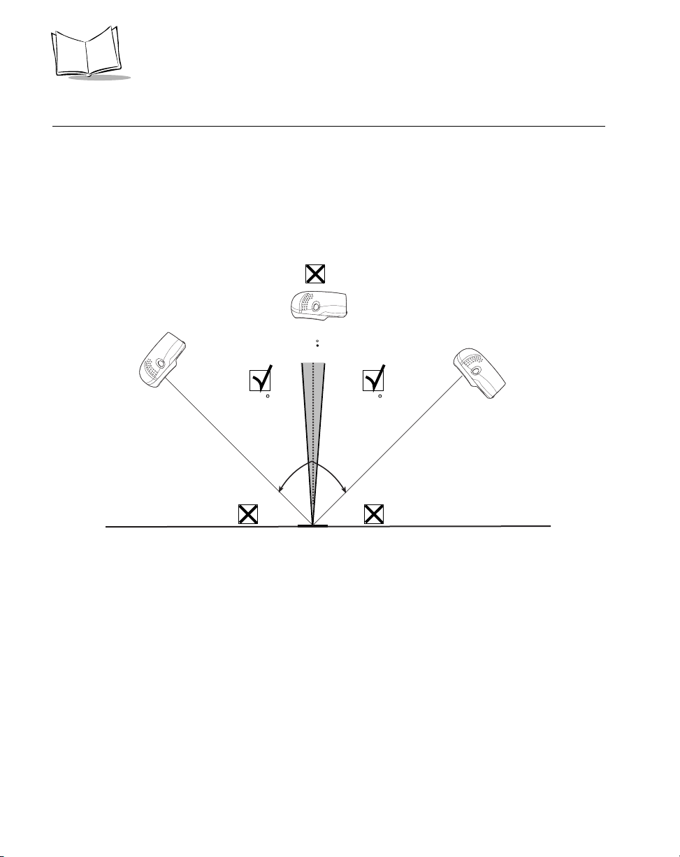
Aiming
Do not hold the scanner directly over the bar code. Laser light reflecting directly back into
the scanner from the bar code is known as specular reflection. This specular reflection can
make decoding difficult.
You can tilt the scanner up to 45° forward or back and achieve a successful decode (Figure
2-9). Simple practice quickly shows what tolerances to work within.
Specular
Reflection
-
+ 4
4545
2-10
Bar
Code
Figure 2-9. Maximum Tilt Angles and Dead Zone
Page 31

Decode Zone
Scanning
in. cm
Note: Typical performance at 73.4 F (23 C)
on high quality symbols.
LS 9208
5 mil
1.0 2.5
0
0
0
7.8 mil (60%)
10.4 mil (80%)
13 mil 100% UPC
6.0
7.5
9.0
050
12.75
W
i
d
t
h
o
f
F
i
e
l
d
12.7
Figure 2-10. WPS100 Decode Zone
2-11
Page 32

Wasp WPS100 Product Reference Guide
2-12
Page 33

Chapter 3
Maintenance and Technical Specifications
Introduction
This chapter covers suggested scanner maintenance, troubleshooting, technical
specifications, and signal descriptions (pinouts).
Maintenance
Cleaning the exit window is the only maintenance required. A dirty window may affect
scanning accuracy.
• Do not allow any abrasive material to touch the window.
• Remove any dirt particles with a damp cloth.
• Wipe the window using a tissue moistened with ammonia/water.
• Do not spray water or other cleaning liquids directly into the window.
3-1
Page 34

Wasp WPS100 Product Reference Guide
Troubleshooting
Problem Possible Causes Possible Solutions
The omni-line scan pattern
does not display when you
follow the directions for
installing the interface cable on
1-3
Scan line(s) display, but bar
code cannot be read.
Bar code is decoded, but not
transmitted to the host.
Scanned data is incorrectly
displayed on the host.
Although the green Power LED
is on, the scanner does not
produce the omni-directional
scan pattern.
No power to the scanner. Ensure the host has power, and is on.
If the scanner uses a separate power
supply, ensure it’s connected to a
working AC outlet.
Interface cable is not
properly connected.
Scanner is not
programmed to read the
bar code type.
Bar code is damaged. Try scanning other bar codes of the
Bar code is too far from
scanner.
Triggered scanning is
being used incorrectly.
The host has disabled
scanning or overridden
parameter settings.
Scanner is not
programmed for the
correct host type.
Scanner is not
programmed to work with
the host. Check scanner
host type parameters or
editing options.
The scanner has gone
into the Low Power “Shut
Down” Mode.
Check for loose cable connections.
Ensure scanner is programmed to
read the bar code type you are
scanning.
same bar code type.
Move the bar code closer to the
scanner.
Press the trigger to activate
decoding. Follow directions on page
2-2.
See the technical person in charge of
scanning.
Scan the appropriate host type bar
code.
• Ensure proper host is selected.
• For keyboard wedge, ensure
scanner is programmed with the
correct country code and that the
CAPS LOCK key is off.
• Ensure editing options (e.g.,
UPCE-to-UPCA Conversion) are
properly programmed.
Press the trigger to awaken the unit,
or change the “Low Power Blink”
parameter on page 4-11.
3-2
Page 35

Maintenance and Technical Specifications
Note: If after performing these checks the symbol still does not scan,
contact Wasp Technical Support at http://
support.waspbarcode.com.
3-3
Page 36

Wasp WPS100 Product Reference Guide
Technical Specifications
Table 3-1. Technical Specifications
Item Description
Physical Characteristics
Dimensions:
without stand: Height
Width
Depth
with stand: Height
Width
Depth
Weight
Power Source Power drawn from Host terminal or external power
Voltage 5.0 VDC ± 10%
Nominal Current 390 mA
5.51 in. (14 cm)
3.49 in. (8.8 cm)
2.96 in. (7.5 cm)
7.18 in. (18.24 cm)
4.83 in. (12.27 cm)
3.73 in. (9.47 cm)
Scanner only: 10.2 oz/320 g
With adjustable stand: 21.5 oz/670 g
supply; depends on Host type.
Power 2 watts
Mounting Options Adjustable multi-mount stand
Color Cash Register White and Twilight Black
Performance Characteristics
Light Source 650nm visible laser diode
Yaw Tolerance (Typical)
Pitch Tolerance (Typical)
Roll Tolerance (Typical)
Print Contrast 25% minimum reflective difference
1
Refers to 100% UPC bar code (80% contrast) located 4 in./10 cm from the scanner nose.
1
1
1
Omnidirectional: ± 50°
Single scan line: ± 50°
Omnidirectional: ± 50°
Single scan line: ± 60°
Omnidirectional: 0 to 360°
Single scan line: ± 40°
3-4
Page 37

Maintenance and Technical Specifications
Table 3-1. Technical Specifications (Continued)
Item Description
Scan Patterns Omnidirectional: 20 interlocking lines,
5 scan lines,
4 lines per angle rastering @ 5Hz
Single scan line capability
Scan Rate Omnidirectional: 1500 scans/second
Single scan line: 75 scans/second
Depth of Field 0-9 in./0-22.9 cm @ 13 mil (100% UPC/EAN)
Nominal Working Range 5 mil: (38%) 1 to 2.5 in./ 2.5 to 6.4 cm
7.8 mil: (60%) 0 to 6 in./ 0 to 15.2 cm
10.4 mil: (80%) 0 to 7.5 in./ 0 to 19 cm
13 mil: (100%) 0 to 9 in./ 0 to 22.9 cm
Width of Field 1.6 in. (40 mm) @ Face
6.7 in. (170 mm) @ 9 in.
Minimum Resolution 5 mil
Decode Capability UPC/EAN/JAN, UPC/EAN with Supplementals, UCC/
EAN 128, Code 128, ISBT 128, Code 39, Code 39
Trioptic, Interleaved 2 of 5, Discrete 2 of 5, Code 93,
Code 11, Codabar, MSI, RSS Variants
Interfaces Supported
User Environment
Operating Temperature 32° to 104°F (0° to 40°C)
Storage Temperature -40° to 158°F (-40° to 70°C)
Humidity 5% to 95% (non-condensing)
Drop Specifications Functions normally after repeated 4 ft (1.2m) drops to
Ambient Light Immunity Immune to normal artificial indoor and natural outdoor
Regulatory
USB and Keyboard Wedge
concrete
(direct sunlight) lighting conditions.
Fluorescent, Incandescent, Mercury Vapor and
Sodium Vapor: 450 Ft Candles (4,844 Lux)
Sunlight: 8000 Ft Candles (86,111 Lux)
3-5
Page 38

Wasp WPS100 Product Reference Guide
Table 3-1. Technical Specifications (Continued)
Item Description
Electrical Safety Certified to UL 1950, CSA C22.2 No. 950 EN60825
Laser Safety CDRH Class IIa Laser Product
IEC 60825 Class 1 Laser Product
EMC
CISPR B, FCC B
3-6
Page 39

Scanner Signal Descriptions
Maintenance and Technical Specifications
Back of scanner
Cable interface port
PIN 10
Interface cable
modular connector
Figure 3-1. Scanner Cable Pinouts
PIN 1
3-7
Page 40

Wasp WPS100 Product Reference Guide
The signal descriptions in Table 3-2 apply to the connector on the scanner and are for
reference only.
Table 3-2. Scanner Signal Pin-outs
Pin USB Keyboard Wedge
1 Jump to Pin 6 Reserved
2 Power Power
3 Ground Ground
4 Reserved KeyClock
5 D + TermData
6 Jump to Pin 1 KeyData
7 D - TermClock
8 Reserved Reserved
9 Reserved Reserved
10 Reserved Reserved
3-8
Page 41

Chapter 4
User Preferences
Introduction
You have the option to program the WPS100 scanner to perform various functions, or
activate different features. This chapter describes each user preference feature and
provides the programming bar codes necessary for selecting these features for your
WPS100 scanner. Before programming, follow the instructions in Chapter 1, Getting
Started.
Your WPS100 is shipped with the settings shown in the User Preferences Default Table on
page 4-3 (also see Appendix A, Standard Default Parameters for all host device and
miscellaneous scanner defaults). If the default values suit your requirements, programming
may not be necessary.
Features values are set by scanning single bar codes or short bar code sequences. The
settings are stored in non-volatile memory and are preserved even when the scanner is
powered down.
4-1
Page 42

Wasp WPS100 Product Reference Guide
If you are not using a USB cable, you must select a host type (see each host chapter for
specific host information). After you hear the power-up beeps, select a host type. This only
needs to be done once, upon the first power-up when connected to a new host.
To return all features to their default values, all you need to do is scan the Set All Defaults
bar code on page 4-5. Throughout the programming bar code menus, default values are
indicated with asterisks (
*).
* Indicates Default
*High Frequency
Feature/Option
Scanning Sequence Examples
In most cases you need only scan one bar code to set a specific parameter value. For
example, if you want to set the beeper tone to high, simply scan the High Frequency
(beeper tone) bar code listed under Beeper Tone on page 4-6. The scanner issues a short
high beep and the LED turns green, signifying a successful parameter entry.
Other parameters, such as specifying Serial Response Time-Out or setting Data
Transmission Formats, require that you scan several bar codes. Refer to Host Serial
Response Time-out on page 6-20 and Scan Data Options on page 8-9 for descriptions of
this procedure.
Errors While Scanning
Unless otherwise specified, if you make an error during a scanning sequence, just re-scan
the correct parameter.
4-2
Page 43

User Preferences
User Preferences Default Parameters
Table 4-1 lists the defaults for user preferences parameters. If you wish to change any
option, scan the appropriate bar code(s) provided in the User Preferences section
beginning on page 4-5.
Note: See Appendix A, Standard Default Parameters for all user
preferences, hosts, symbologies, and miscellaneous default
parameters.
Table 4-1. User Preferences Default Table
Page
Parameter Default
User Preferences
Set Default Parameter All Defaults 4-5
Number
Beeper Tone High 4-6
Beeper Volume High 4-7
Volume Change Trigger Delay 5.0 Sec 4-8
Laser On Time 3.0 Sec 4-9
Beep After Good Decode Enable 4-10
Low Power Blink Blink 4-11
Scan Pattern Mode Rastering 4-12
Single-Line Aim Duration 2 sec 4-13
Time-out Between Same Symbol 0.6 sec 4-15
Time-out Between Different Symbols 0.2 sec 4-15
Time Delay to Low Power Mode 30 Minutes 4-16
4-3
Page 44

Wasp WPS100 Product Reference Guide
Table 4-1. User Preferences Default Table
Parameter Default
Linear UPC/EAN Decode Disable 4-18
Page
Number
4-4
Page 45

User Preferences
User Preferences
Set Default Parameter
Scanning this bar code returns all parameters to the default values listed in Table A-1 on
page A-1.
Set All Defaults
4-5
Page 46

Wasp WPS100 Product Reference Guide
Beeper Tone
To select a decode beep frequency (tone), scan the Low Frequency, Medium Frequency,
or High Frequency bar code.
Low Frequency
4-6
Medium Frequency
*High Frequency
Page 47

User Preferences
Beeper Volume
To select a beeper volume, scan the Low Volu m e , Medium Volume, or High Volume bar
code.
Low Volume
Medium Volume
*High Volume
4-7
Page 48

Wasp WPS100 Product Reference Guide
Volume Change Trigger Delay
The volume on the WPS100 scanner is adjusted by pressing and holding the trigger for a
certain amount of time, after which the scanner changes the volumes, and beeps with the
new volume.
The parameters below control the length of time needed to hold the trigger before the
volume is adjusted.
Volume Trigger Duration 3 sec
4-8
*Volume Trigger Duration 5 sec
Volume Trigger Duration 7 sec
Page 49

User Preferences
Laser On Time
This parameter sets the maximum time that decode processing continues during a scan
attempt. It is programmable in 0.1 second increments from 0.5 to 10 seconds. The default
Laser On Time is 3.0 seconds.
To set a Laser On Time, scan the bar code below. Next, scan two numeric bar codes
beginning on page D-1 in Appendix D that correspond to the desired on time. Single digit
numbers must have a leading zero. For example, to set an On Time of 0.5 seconds, scan
the bar code below, then scan the “0” and “5” bar codes. If you make an error, or wish to
change your selection, scan Cancel on page D-5.
Laser On Time
4-9
Page 50

Wasp WPS100 Product Reference Guide
Beep After Good Decode
Scan a bar code below to select whether or not the scanner beeps after a good decode. If
Do Not Beep After Good Decode is selected, the beeper still operates during parameter
menu scanning and indicates error conditions.
*Beep After Good Decode
(Enable)
4-10
Do Not Beep After Good Decode
(Disable)
Page 51

User Preferences
Low Power Blink
After a period of inactivity, the scanner will go into a reduced power mode. This parameter
controls how aggressively power is conserved, and therefore determines the method of
waking the scanner up.
If “Low Power - Blink Mode” is selected, then the scanner (after a period of inactivity) will
blink infrequently to save power. To restore the scanner to full power mode, the user must
simply use the scanner by presenting a barcode.
If “Motor and Laser Shut Down” is selected, then the scanner (after a period of inactivity)
will turn off the motor and laser, but leave the green Power LED lit. The user must then
depress the trigger to awaken the scanner to its full power mode.
*Low Power - Blink Mode
Low Power - Shut Down
4-11
Page 52

Wasp WPS100 Product Reference Guide
Scan Pattern Mode
The WPS100 has a very aggressive scan pattern that is not only omnidirectional, but also
raster. If a static omnidirectional pattern is desired, scan the “Omnidirectional Pattern”
parameter below to change the scan pattern.
*Rastering Omnidirectional Pattern
4-12
Omnidirectional Pattern
Page 53

User Preferences
Single-Line Aim Duration
The LS 9200 can enter the single-line scan mode by tapping the trigger. Once in this mode,
each trigger pull will attempt to decode the barcode in front of the scanner. After a period
of inactivity while the trigger is not pressed, the scanner will revert to the omnidirectional
pattern.
This parameter controls the length of the period of inactivity in single-line mode before the
scanner reverts to the omnidirectional pattern.
*Aim Duration 2 sec
Aim Duration 3 sec
4-13
Page 54

Wasp WPS100 Product Reference Guide
Single-Line Aim Duration (Continued)
Aim Duration 4 sec
Aim Duration 5 sec
4-14
Page 55

User Preferences
Timeout Between Decodes
Timeout Between Decodes, Same Symbol
This parameter sets the minimum time between decodes of different symbols. It is
programmable in 0.1-second increments from 0.0 to 9.9 seconds. Setting this above 0.4
seconds is recommended.) The default for this parameter is 0.6 seconds.
Scan the bar code below to select a new timeout. Next, scan two numeric bar codes
beginning in Numeric Bar Codes on page D-1 that correspond to the desired timeout.
Single digit numbers must have a leading zero. For example, to set a timeout of 0.5
seconds, scan the bar code below, then scan the “0” and “5” bar codes. If you make an
error, or wish to change your selection, scan Cancel on page D-5.
Timeout Between Same Symbol
Timeout Between Decodes, Different Symbol
This parameter sets the minimum time between decodes of different symbols. It is
programmable in 0.1-second increments from 0.0 to 9.9 seconds. The default for this
parameter is 0.2 seconds.
Scan the bar code below to select a new timeout. Next, scan two numeric bar codes
beginning in Numeric Bar Codes on page D-1 that correspond to the desired timeout.
Single digit numbers must have a leading zero. For example, to set a timeout of 0.5
seconds, scan the bar code below, then scan the “0” and “5” bar codes. If you make an
error, or wish to change your selection, scan Cancel on page D-5.
Timeout Between Different Symbol
4-15
Page 56

Wasp WPS100 Product Reference Guide
Time Delay to Low Power Mode
This parameter sets the time that the scanner remains active after any scanning activity.
Scan one of the four options. Depending on the selection, the scanner enters a sleep mode
15, 30, 60 or 90 minutes after the last attempted decode. To awaken the scanner, please
refer to the explanation of the Low Power Blink parameter on page 4-11.
15 Minutes
4-16
*30 Minutes
Page 57

Time Delay to Low Power Mode (Continued)
60 Minutes
User Preferences
90 Minutes
4-17
Page 58

Wasp WPS100 Product Reference Guide
Linear UPC/EAN Decode
This option applies to code types containing two adjacent blocks (e.g., UPC-A, EAN-8,
EAN-13). When enabled, a bar code is transmitted only when both the left and right blocks
are successfully decoded within one laser scan. Enable this option when bar codes are in
proximity to each other.
Enable Linear UPC/EAN Decode
4-18
*Disable Linear UPC/EAN Decode
Page 59

Chapter 5
Keyboard Wedge Interface
Introduction
This chapter covers Keyboard Wedge interface information for setting up your scanner.
This interface type is used to attach the scanner between the keyboard and host computer.
The scanner translates the bar code data into keystrokes. The host computer accepts the
keystrokes as if they originate from the keyboard.
This mode of operation allows adding bar code reading functionality to a system designed
for manual keyboard input. In this mode the keyboard keystrokes are simply passed
through.
Throughout the programming bar code menus, default values are indicated with asterisks
(
*).
* Indicates Default
*North American
Feature/Option
5-1
Page 60

Wasp WPS100 Product Reference Guide
Connecting a Keyboard Wedge Interface
Male DIN Keyboard
Y- ca bl e
Power supply
(if needed)
Figure 5-1. Keyboard Wedge Connection with Y-cable
To connect the Keyboard Wedge Y-cable:
1. Switch off the host and unplug the keyboard connector.
2. Attach the modular connector of the Y-cable to the cable interface port on the
scanner. (See Installing the Interface Cable on page 1-3.)
3. Connect the round male DIN host connector of the Y-cable to the keyboard port on
the host device.
4. Connect the round female DIN keyboard connector of the Y-cable to the keyboard.
5. If needed, attach the optional power supply to the connector in the middle of the Ycable.
6. Ensure that all connections are secure.
7. Switch on your host system.
8. Scan the appropriate bar codes in this chapter to configure the scanner.
5-2
Page 61

Keyboard Wedge Interface
Keyboard Wedge Default Parameters
Table 5-1 lists the defaults for Keyboard Wedge host parameters. If you wish to change any
option, scan the appropriate bar code(s) provided in the Keyboard Wedge Host Parameters
section beginning on page 5-4.
Note: See Appendix A, Standard Default Parameters for all user
preferences, hosts, symbologies, and miscellaneous default
parameters.
Table 5-1. Keyboard Wedge Host Default Table
Page
Parameter Default
Keyboard Wedge Host Parameters
Number
Keyboard Wedge Host Type IBM PC/AT & IBM PC Compatibles
Country Types (Country Codes) North American 5-6
Ignore Unknown Characters Send Bar Codes 5-10
Keystroke Delay No Delay 5-11
Intra-Keystroke Delay Disable 5-12
Alternate Numeric Keypad Emulation Disable 5-13
Caps Lock On Disable 5-14
Caps Lock Override Disable 5-15
Convert Wedge Data No Convert 5-16
Function Key Mapping Disable 5-17
FN1 Substitution Disable 5-18
Send Make Break Disable 5-19
1
User selection is required to configure this interface and this is the most common selection.
1
5-4
5-3
Page 62

Wasp WPS100 Product Reference Guide
Keyboard Wedge Host Types
Keyboard Wedge Host Types
Select your keyboard wedge host by scanning one of the bar codes below.
IBM PC/AT & IBM PC Compatibles
IBM PS/2 (Model 30)
1
5-4
IBM AT NOTEBOOK
Page 63

Keyboard Wedge Interface
Keyboard Wedge Host Types (Continued)
IBM XT
NCR 7052
Note:1User selection is required to configure this interface and this is the
most common selection.
5-5
Page 64

Wasp WPS100 Product Reference Guide
Keyboard Wedge Country Types (Country Codes)
Scan the bar code corresponding to your keyboard type. If your particular keyboard type is
not listed, see Alternate Numeric Keypad Emulation on page 5-13.
*North American
5-6
German Windows
French Windows
Page 65

Keyboard Wedge Interface
Keyboard Wedge Country Types (Continued)
French Canadian Win 95/98
French Canadian Windows XP/2000
Spanish Windows
5-7
Page 66

Wasp WPS100 Product Reference Guide
Keyboard Wedge Country Types (Continued)
Italian Windows
5-8
Swedish Windows
UK English Windows
Page 67

Keyboard Wedge Interface
Keyboard Wedge Country Types (Continued)
Japanese Windows
Brazilian/Portuguese Windows
5-9
Page 68

Wasp WPS100 Product Reference Guide
Ignore Unknown Characters
Unknown characters are characters the host does not recognize. When Send Bar Codes
With Unknown Characters is selected, all bar code data is sent except for unknown
characters, and no error beeps sound on the scanner. When Do Not Send Bar Codes
With Unknown Characters is selected, bar code data is sent up to the first unknown
character and then an error beep will sound on the scanner.
*Send Bar Codes With Unknown
Characters
Do Not Send Bar Codes With Unknown Characters
5-10
Page 69

Keyboard Wedge Interface
Keystroke Delay
This is the delay in milliseconds between emulated keystrokes. Scan a bar code below to
increase the delay when hosts require a slower transmission of data.
*No Delay
Medium Delay (20 msec)
Long Delay (40 msec)
5-11
Page 70

Wasp WPS100 Product Reference Guide
Intra-Keystroke Delay
When enabled, an additional delay is inserted between each emulated key depression and
release. This sets the Keystroke Delay parameter to a minimum of 5 msec as well.
Enable
5-12
*Disable
Page 71

Keyboard Wedge Interface
Alternate Numeric Keypad Emulation
This allows emulation of most other country keyboard types not listed in Keyboard Wedge
Country Types (Country Codes) on page 5-6 in a Microsoft operating system environment.
Enable Alternate Numeric Keypad
*Disable Alternate Numeric Keypad
5-13
Page 72

Wasp WPS100 Product Reference Guide
Caps Lock On
When enabled, the scanner emulates keystrokes as if the Caps Lock key is always
pressed.
Enable Caps Lock On
5-14
*Disable Caps Lock On
Page 73

Keyboard Wedge Interface
Caps Lock Override
When enabled, on AT or AT Notebook hosts, the keyboard ignores the state of the Caps
Lock key. Therefore, an ‘A’ in the bar code is sent as an ‘A’ no matter what the state of the
keyboard’s Caps Lock key.
Enable Caps Lock Override
*Disable Caps Lock Override
Note: If both Caps Lock On and Caps Lock Override are enabled, Caps
Lock Override takes precedence.
5-15
Page 74

Wasp WPS100 Product Reference Guide
Convert Wedge Data
When enabled, the scanner will convert all bar code data to the selected case.
Convert to Upper Case
Convert to Lower Case
5-16
*No Convert
Page 75

Keyboard Wedge Interface
Function Key Mapping
ASCII values under 32 are normally sent as a control-key sequences (see Table 6-2 on
page 6-18). When this parameter is enabled, the keys in bold are sent in place of the
standard key mapping. Table entries that do not have a bold entry remain the same
whether or not this parameter is enabled.
Enable
*Disable
5-17
Page 76

Wasp WPS100 Product Reference Guide
FN1 Substitution
When enabled, this allows replacement of any FN1 characters in an EAN 128 bar code with
a Key Category and Key Value choose by the user (see FN1 Substitution Values on page
8-8).
Enable
5-18
*Disable
Page 77

Keyboard Wedge Interface
Send Make Break
When enabled, the scan codes for releasing a key are not sent.
*Send Make and Break Scan Codes
Send Make Scan Code Only
5-19
Page 78

Wasp WPS100 Product Reference Guide
Keyboard Maps
The following keyboard maps are provided for prefix/suffix keystroke parameters. To
program the prefix/suffix values, see the bar codes on page 8-5.
Figure 5-2. IBM PS2 Type Keyboard
.
5-20
5001
5003
5005
5007
5009
5002
5004
5006
5008
5010
7014
7009
Figure 5-3. IBM PC/XT
7008
7013
7012
7004
7011 7002
7003
7006
Page 79

Keyboard Wedge Interface
e
5001
5003
5005
5007
5009
5002
5004
5006
5008
5010
7009
5002
5001
5003
5004
5005 5006
5007
5008
5009
5010
Figure 5-4. IBM PC/AT
5011
1048
5012
(1048 if double key)
1046
7008
7014
7012
7013
7004
1045
5013
5014
5015
1043
5016
5018
5017
7013
5019
(7013 if double k
7011
7003
7002
Figure 5-5. NCR 7052 32-KEY
5-21
Page 80

Wasp WPS100 Product Reference Guide
1066
1065
1072
1073
1079 1080
5002
5001
5003
5004
5005 5006
5007
5008
5009
5010
5012
1068
1075
1082
1046
1069
1076
1083 1084
1045
5014
1043
5017
7013
(1043 if double key)
1067
1074
1081
5011
1048
(1048 if double key)
Figure 5-6. NCR 7052 58-KEY
1070
1077
5013
5015
5016
5018
5019
1071
1078
1085
1086
1087
1088
1089
1090
5-22
Page 81

ASCII Character Set
Note: Code 39 Full ASCII interprets the bar code special character
($ + % /) preceding a Code 39 character and assigns an ASCII
character value to the pair. For example, when Code 39 Full ASCII
is enabled and a +B is scanned, it is interpreted as b, %J as ?, and
%V as @. Scanning ABC%I outputs the keystroke equivalent of
ABC >.
Table 5-2. Keyboard Wedge ASCII Character Set
ASCII
Value
1001 $A CTRL A
1002 $B CTRL B
1003 $C CTRL C
1004 $D CTRL D
1005 $E CTRL E
Keyboard Wedge Interface
Full ASCII Code
39 Encode Char.
Keystroke
1006 $F CTRL F
1007 $G CTRL G
1008 $H CTRL H/
BACKSPACE
1009 $I CTRL I/
HORIZONTAL
1010 $J CTRL J
1011 $K CTRL K
1012 $L CTRL L
1013 $M CTRL M/
1014 $N CTRL N
1015 $O CTRL O
TAB
ENTER
1
a
1
5-23
Page 82

Wasp WPS100 Product Reference Guide
Table 5-2. Keyboard Wedge ASCII Character Set (Continued)
1016 $P CTRL P
1017 $Q CTRL Q
1018 $R CTRL R
1019 $S CTRL S
1020 $T CTRL T
1021 $U CTRL U
1022 $V CTRL V
1023 $W CTRL W
1024 $X CTRL X
1025 $Y CTRL Y
1026 $Z CTRL Z
1027 %A NONE/ESC
1028 %B NONE
1029 %C NONE
1030 %D NONE
1
5-24
1031 %E NONE
1032 Space Space
1033 /A !
1034 /B “
1035 /C #
1036 /D $
1037 /E %
1038 /F &
1039 /G ‘
1040 /H (
1041 /I )
1042 /J *
Page 83

Keyboard Wedge Interface
Table 5-2. Keyboard Wedge ASCII Character Set (Continued)
1043 /K +
1044 /L ,
1045 - -
1046 . .
1047 /O /
1048 0 0
1049 1 1
1050 2 2
1051 3 3
1052 4 4
1053 5 5
1054 6 6
1055 7 7
1056 8 8
1057 9 9
1058 /Z :
1059 %F ;
1060 %G <
1061 %H =
1062 %I >
1063 %J ?
1064 %V @
1065 A A
1066 B B
1067 C C
1068 D D
1069 E E
5-25
Page 84

Wasp WPS100 Product Reference Guide
Table 5-2. Keyboard Wedge ASCII Character Set (Continued)
1070 F F
1071 G G
1072 H H
1073 I I
1074 J J
1075 K K
1076 L L
1077 M M
1078 N N
1079 O O
1080 P P
1081 Q Q
1082 R R
1083 S S
1084 T T
5-26
1085 U U
1086 V V
1087 W W
1088 X X
1089 Y Y
1090 Z Z
1091 %K [
1092 %L \
1093 %M ]
1094 %N ^
1095 %O _
1096 %W ‘
Page 85

Keyboard Wedge Interface
Table 5-2. Keyboard Wedge ASCII Character Set (Continued)
1097 +A a
1098 +B b
1099 +C c
110 0 +D d
110 1 + E e
110 2 +F f
110 3 +G g
110 4 +H h
110 5 +I i
110 6 + J j
110 7 + K k
110 8 +L l
110 9 +M m
1110 +N n
1111 + O o
1112 +P p
1113 +Q q
1114 +R r
1115 +S s
1116 + T t
1117 +U u
1118 +V v
1119 + W w
112 0 + X x
112 1 + Y y
112 2 +Z z
112 3 %P {
5-27
Page 86

Wasp WPS100 Product Reference Guide
Table 5-2. Keyboard Wedge ASCII Character Set (Continued)
112 4 % Q |
112 5 %R }
112 6 %S ~
ALT Keys Keystroke
2065 ALT A
2066 ALT B
2067 ALT C
2068 ALT D
2069 ALT E
2070 ALT F
2071 ALT G
2072 ALT H
2073 ALT I
2074 ALT J
2075 ALT K
5-28
2076 ALT L
2077 ALT M
2078 ALT N
2079 ALT O
2080 ALT P
2081 ALT Q
2082 ALT R
2083 ALT S
2084 ALT T
2085 ALT U
2086 ALT V
2087 ALT W
Page 87

Keyboard Wedge Interface
Table 5-2. Keyboard Wedge ASCII Character Set (Continued)
2088 ALT X
2089 ALT Y
2090 ALT Z
GUI Shift Keys
The Apple™ iMac keyboard has an apple key on either
side of the space bar. Windows-based systems have a
GUI key to the left of the left ALT key, and to the right of
the right ALT key.
Other
Keystroke
Value
3000 Right Control Key
3048 GUI 0
3049 GUI 1
3050 GUI 2
3051 GUI 3
3052 GUI 4
3053 GUI 5
3054 GUI 6
3055 GUI 7
3056 GUI 8
3057 GUI 9
3065 GUI A
3066 GUI B
3067 GUI C
3068 GUI D
3069 GUI E
3070 GUI F
3071 GUI G
3072 GUI H
5-29
Page 88

Wasp WPS100 Product Reference Guide
Table 5-2. Keyboard Wedge ASCII Character Set (Continued)
3073 GUI I
3074 GUI J
3075 GUI K
3076 GUI L
3077 GUI M
3078 GUI N
3079 GUI O
3080 GUI P
3081 GUI Q
3082 GUI R
3083 GUI S
3084 GUI T
3085 GUI U
3086 GUI V
3087 GUI W
5-30
3088 GUI X
3089 GUI Y
3090 GUI Z
F Keys Keystroke
5001 F1
5002 F2
5003 F3
5004 F4
5005 F5
5006 F6
5007 F7
5008 F8
Page 89

Keyboard Wedge Interface
Table 5-2. Keyboard Wedge ASCII Character Set (Continued)
5009 F9
5010 F10
5011 F11
5012 F12
5013 F13
5014 F14
5015 F15
5016 F16
5017 F17
5018 F18
5019 F19
5020 F20
5021 F21
5022 F22
5023 F23
5024 F24
Numeric
Keypad
6042 *
6043 +
6044 undefined
6045 -
6046 .
6047 /
6048 0
6049 1
6050 2
6051 3
Keystroke
5-31
Page 90

Wasp WPS100 Product Reference Guide
Table 5-2. Keyboard Wedge ASCII Character Set (Continued)
6052 4
6053 5
6054 6
6055 7
6056 8
6057 9
6058 Enter
6059 Num Lock
Extended
Keypad
7001 Break
7002 Delete
7003 Pg Up
7004 End
7005 Pg Dn
Keystroke
5-32
7006 Pause
7007 Scroll Lock
7008 Backspace
7009 Tab
7010 Print Screen
7011 Insert
7012 Home
7013 Enter
7014 Escape
7015 Up Arrow
7016 Dn Arrow
7017 Left Arrow
7018 Right Arrow
Page 91

Keyboard Wedge Interface
a. The Keystroke in bold is sent only if the “Function Key Mapping” parameter is enabled. Otherwise, the unbolded keystroke is sent.
5-33
Page 92

Wasp WPS100 Product Reference Guide
5-34
Page 93

Chapter 6
USB Interface
Introduction
This chapter covers the connection and setup of the scanner to a USB host. The scanner
attaches directly to a USB host, or a powered USB hub, and is powered by it. No additional
power supply is required.
Throughout the programming bar code menus, default values are indicated with asterisks
(
*).
*North American, Standard USB Keyboard
* Indicates Default
Feature/Option
6-1
Page 94

Wasp WPS100 Product Reference Guide
Connecting a USB Interface
Interface cable
Figure 6-1. USB Connection
The scanner connects with USB capable hosts including:
USB Series A Connector
• Desktop PCs and Notebooks
• Apple™ iMac, G4, iBooks (North America only)
• IBM SurePOS terminals
• Sun, IBM, and other network computers that support more than one keyboard.
The following operating systems support the scanner through USB:
• Windows 98, 2000, ME, XP
• MacOS 8.5 and above
• IBM 4690 OS.
The scanner will also interface with other USB hosts which support USB Human Interface
Devices (HID). For more information on USB technology, hosts, and peripheral devices,
visit www.symbol.com/usb.
To set up your scanner:
1. Connect the USB interface cable to the rear of the scanner, as described in
Installing the Interface Cable on page 1-3.
6-2
Page 95

USB Interface
2. Plug the series A connector in the USB host or hub, or plug the Plus Power
connector in an available port of the IBM SurePOS terminal.
3. Select the USB device type. See USB Device Type on page 6-5.
4. On first installation when using Windows, the software prompts you to select or
install the "Human Interface Device" driver. To install the "Human Interface Device"
driver provided by Windows click "Next" through all the choices and click "Finished"
on the last choice. The scanner powers up during this installation.
5. If you are not using a North American keyboard, scan the appropriate country bar
code under USB Country Keyboard Types (Country Codes) on page 6-6.
If you are having any problems with your system, see Troubleshooting on page 3-2.
6-3
Page 96

Wasp WPS100 Product Reference Guide
USB Default Parameters
Table 6-1 lists the defaults for USB host parameters. If you wish to change any option, scan
the appropriate bar code(s) provided in the Parameter Descriptions section beginning on
page 6-5.
Note: See Appendix A, Standard Default Parameters for all user
preferences, hosts, symbologies, and miscellaneous default
parameters.
Table 6-1. USB Host Default Table
Page
Parameter Default
USB Host Parameters
Number
USB Device Type HID (Human Interface
Device) Keyboard
Emulation
USB Country Keyboard Types (Country Codes) North American 6-6
USB Keystroke Delay No Delay 6-10
USB CAPS Lock Override Disable 6-11
USB Ignore Unknown Characters Send Bar Codes 6-12
Emulate Keypad Disable 6-13
USB Keyboard FN1 Substitution Disable 6-14
Function Key Mapping Disable 6-15
Simulated Caps Lock Disable 6-16
Convert Case Disable 6-17
6-5
6-4
Page 97

USB Host Parameters
USB Device Type
Select the desired USB device type.
Note: When changing USB Device Types, the scanner automatically
restarts. The scanner issues the standard startup beep sequences.
*HID Keyboard Emulation
USB Interface
IB M Table Top USB
IBM Hand-Held USB
6-5
Page 98

Wasp WPS100 Product Reference Guide
USB Country Keyboard Types (Country Codes)
Scan the bar code corresponding to your keyboard type. This setting applies only to the
USB HID Keyboard Emulation device.
Note: When changing Country Selection, the scanner automatically
restarts. The scanner issues the standard startup beep sequences.
*North American, Standard USB Keyboard
6-6
French, Windows
German, Windows
Page 99

USB Country Keyboard Types (Continued)
French Canadian, Windows
French Canadian, Windows 2000/XP
USB Interface
Spanish (Traditional), Windows
6-7
Page 100

Wasp WPS100 Product Reference Guide
USB Country Keyboard Types (Continued)
Italian, Windows
6-8
Swedish, Windows
UK English, Windows
 Loading...