

Page 1

WPL606 Thermal Label Printer
User’s Guide
For Wasp Technologies
DT/TT Printer
Copyright Wasp Bar Code Technologies 2004.
All rights reserved.
No part of this publication may be reproduced or transmitted in any form or by any
means without the written permission of Wasp Bar Code Technologies. The
information contained in this document is subject to change without notice.
Wasp is a trademark of Wasp Bar Code Technologies. All other trademarks are the
property of their respective owners.
Document Revised August 13th, 2001
Page 2

CONTENTS
1. Product Introduction ..............................................................1
1.1 Specification .................................................................................................. 1
1.1.1 Printer ....................................................................................................... 1
1.1.2 Environment .............................................................................................. 1
1.1.3 Hardware................................................................................................... 1
1.1.4 Bar Code................................................................................................... 2
1.2 Optional Items................................................................................................ 2
1.3 Supplies ......................................................................................................... 2
1.3.1 Label Specification .................................................................................... 2
1.3.2 Ribbon Specification.................................................................................. 2
2. Getting Started.......................................................................3
2.1 Unpacking and Inspection.............................................................................. 3
2.2 Equipment Checklist ...................................................................................... 3
2.3 Printer Parts................................................................................................... 3
2.4 Buttons, Indicators and adjustment knobs ..................................................... 5
3. Set Up....................................................................................7
3.1 Setting Up the Printer .................................................................................... 7
3.2 Ribbon Installation ......................................................................................... 7
3.3 Label Roll Installation..................................................................................... 9
3.4 Peel-off Sensor Installation (Sold Separately) ............................................. 10
3.5 Loading Label For Peel-off Mode................................................................. 11
3.6 Self-test ....................................................................................................... 12
3.7 Dump Mode ................................................................................................. 12
4. Calibration ...........................................................................14
4.1 Printer Initialization ...................................................................................... 14
4.2 Gap/Black Mark Sensor Calibration Utility ................................................... 15
4.3 Troubleshooting Guide................................................................................. 16
5. Printer Maintenance ............................................................17
5.1 Print Head Cleaning..................................................................................... 17
5.2 Printer Cover Cleaning................................................................................. 17
5.3 Internal Parts Cleaning ................................................................................ 17
6. Support and Warranty..........................................................18
6.1 Product Support........................................................................................... 18
6.2 Warranty Information ................................................................................... 18
Page 3

Appendix 1: LCD Control Panel Operation Map.......................19
3
Page 4

Page 5
1. Product Introduction
Thank you for purchasing the W606 bar code printer. This guide will describe all
of the common operations needed to operate and maintain your W606.
1.1 Specification
1.1.1 Printer
Item Specification
Printing Mode Thermal transfer and direct thermal
Resolution
203DPI
Max. Print Length 1000 mm ( 39.4” )
Max. Print Width 104 mm ( 4” )
Print Speed 3,4,5,6 ips
1.1.2 Environment
Operating Environment
Temperature 5 - 40 OC ( 41OF - 104 OF )
Humidity 30 % - 85 %
Storage Environment
Temperature -10 - 60 OC ( 14 OF - 140 OF )
Humidity 20 - 95 %
Ventilation Free air environment
1.1.3 Hardware
Label gap sensor, Paper end sensor, Ribbon end
sensor, Ribbon near end sensor, Black mark sensor,
Sensors
Head open sensor, Case open sensor, Label taken
sensor, Paper near end sensor.
Memory
Interface
Flash ROM (2MB), DRAM (2MB) and 8M optional
flash ROM (memory module)
RS-232C, Centronics (SPP), USBV1.1, Internal LAN
adapter (optional).
Power 100 - 240 V universal switching power supply.
1
Page 6
1.1.4 Bar Code
Code 39, Code 93, Code128 subsets A B and C, Code 11, Codabar,
Interleaved 2 of 5, EAN-8, EAN-13, EAN-128, UPC-A, UPC-E, EAN, UPC,
EAN 2 or 5 digit add-on, UPC 2 or 5 digit Add-on, CPOST, MSI Plessy, Postnet,
EAN-14, ITF-14, PDF-417, Maxicode, DataMatrix, QR Code
1.2 Optional Items
Cutter module
Peel off sensor
Portable LCD keyboard
Memory
Internal or External Ethernet print server
1.3 Supplies
1.3.1 Label Specification
Item Specification
Type Roll and label, continuous, die-cut, fan-fold, ticket
Label Width 25.4 - 116 mm ( 1” - 4.4” )
Label Length 10 - 999 mm ( 0.4” - 39.33” )
Label Thickness 0.0 - 0.25 mm ( .003” - .001” )
Label Roll Diameter 203 mm Maximum ( 9.8” )
Roll Core Diameter 25 or 77 mm ( 1” or 3”)
Black Mark Width 3 mm Minimum ( .12” )
1.3.2 Ribbon Specification
Item Specification
Ribbon Width
25.4~114.3 mm ( 1” – 4.5” )
Ribbon Length 300 m Maximum ( 984’ )
2
Page 7
2. Getting Started
r
2.1 Unpacking and Inspection
After receiving the bar code printer, carefully inspect the device and its packaging.
The printer is specially packaged to withstand damage in shipping. In case of
evident damage, contact the carrier directly to specify the nature and extent of
damage. Please retain the packaging materials in case you need to reship the
printer.
2.2 Equipment Checklist
W606 printer unit
Quick installation guide
Power cord
Centronics interface cable
3” (76.2 mm ) paper core adapter
Software CD disc
If any parts are missing, please contact Product Support. For contact information
see the Product Support section at the end of this document.
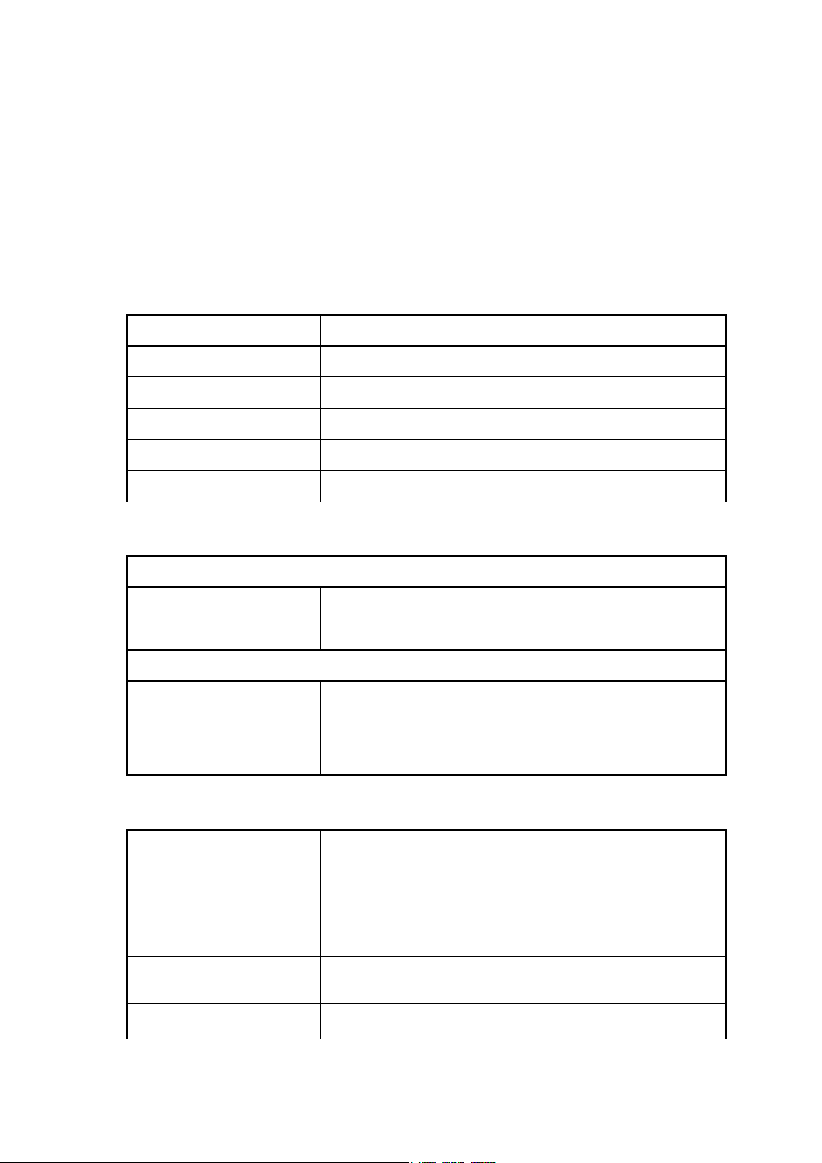
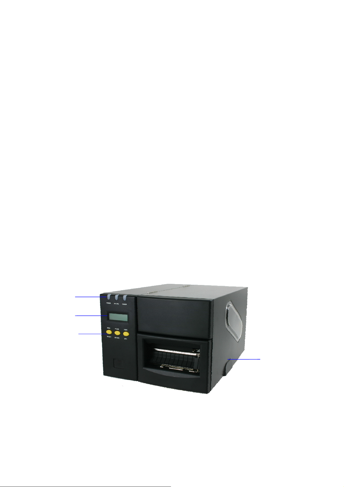
2.3 Printer Parts
Lights
LCD Display
Buttons
Printer Right
Side Cove
Figure 1: Printer front view
3
Page 8
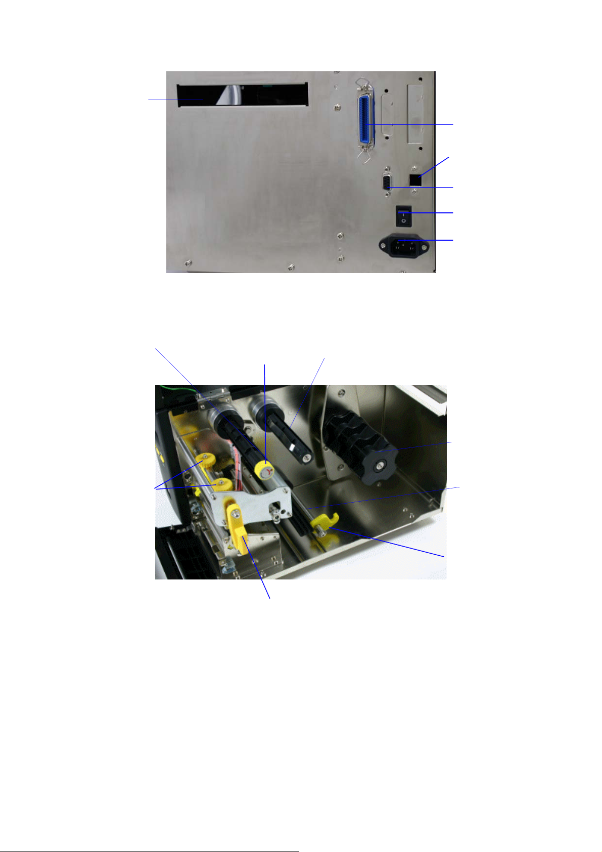
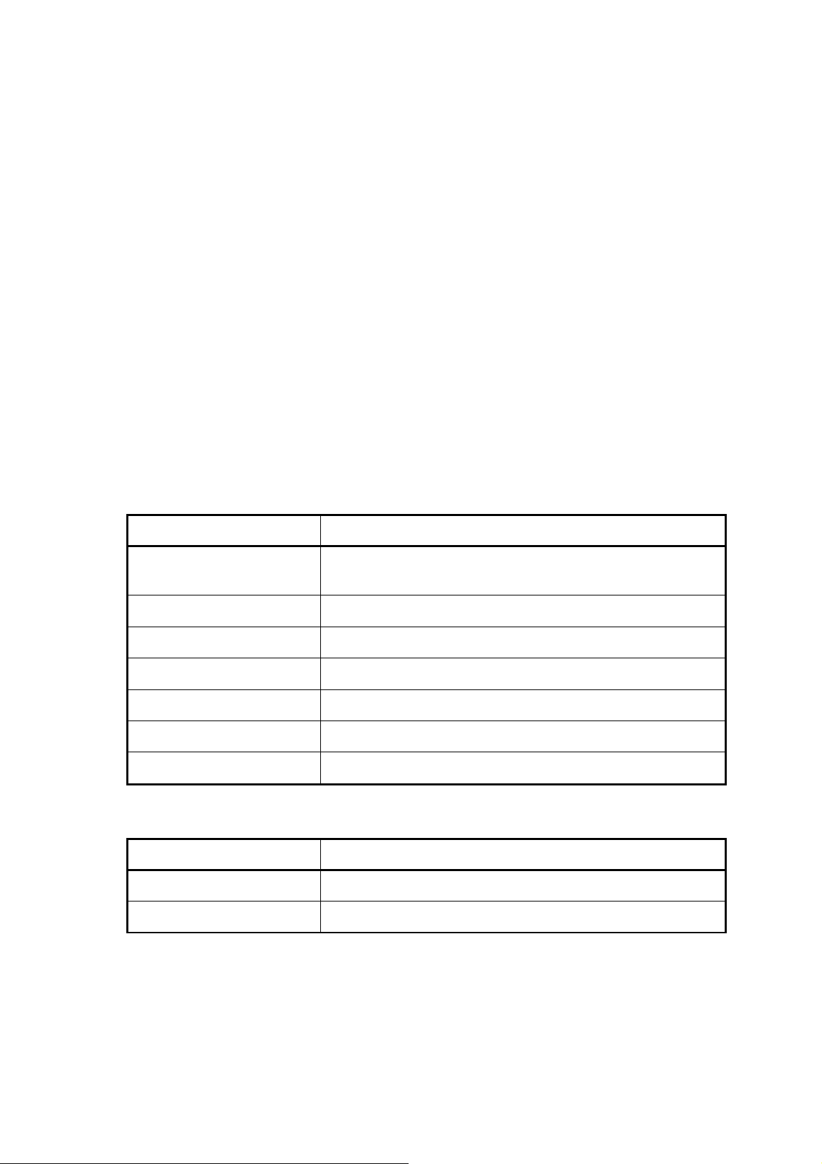
External Label
Feed Opening
Ribbon Rewind Spindle
Figure 2: Printer rear view
Ribbon Tension
Adjustment Knob
Ribbon Supply Spindle
Centronics Port
USB port
RS-232C Port
Power Switch
Power Supply
Connector
Print Head Pressure
Adjustment Knob
Print Head Lift Lever
Figure 3: Printer interior view
Label Spindle
Media Guide Bar
Label Guide
4
Page 9

2.4 Buttons, Indicators and adjustment knobs
Power Indicator
When the printer is in the power-on state, the Power indicator is lit.
On-Line Indicator
This green On-Line indicator is lit when the printer is ready. The On-Line
indicator blinks when in PAUSE mode.
Error Indicator
The red Error indicator illuminates in the event of a printer error, such as
memory full, carriage open, cutter error and so forth.
MENU/SELECT Button
Press the MENU button to enter printer setup mode. Press the MENU button
again to advance the cursor to the next menu item. (Printer Setup, Sensor Setup,
System Setup, File Setup and Printer Test) For more information, please refer to
Appendix 1 for the structure and operation logic of the menu.
PAUSE/EXE/INC Button
This button combines three functions:
A. PAUSE: If the printer is in the Ready status, pressing the PAUSE:
(1) Stops at the completion of printing of the current label
(2) The On-Line LED flashes, and
(3) The printer holds all data in memory. This allows for trouble-free
replacement of label stock and thermal transfer ribbon. A second depression
of the PAUSE button will restart the printer.
B. EXE/INC (Execute/Increment): If the printer is in the setup mode, Press INC
button to increase the value of parameters. Press EXE to execute the
selected item.
FEED/DEC Button
This button also has dual functions.
Press the FEED button and the printer will advance one label.
Press the DEC button to decrease the value of parameters.
Print Head Lift Lever
When the Print Head Lift Lever is opened, the On-Line LED will be turned off, the
5
Page 10

LCD display shows “Carriage Open” and the red Error light will come on. After
closing the print head lift lever, the On-Line light will blink. Press the FEED button
to re-register the label.
Ribbon Tension Adjustment Knob
The Ribbon Tension Adjustment Knob offers 6 levels of tension to adjust for
different widths of ribbon. Turn the ribbon tension knob clockwise and you will
hear a light click sound as the gear changes. The levels increase the tension
from 0 to the tightest at 5. You will hear a louder click when level 0 is selected to
indicate reset.
Note: Use the lowest setting possible for longer print head life.
Print Head Pressure Adjustment Knob
The Print Head Adjustment Knobs are used to fine tune print quality for different
thickness of media. Turning the knobs increases or decreases the pressure on
the media by the print head. The knobs should always be set to the same level. If
setting them to different levels fixes a printing problem you should clean the print
head and consider replacing it.
Print Head
Pressure
Knobs
Print Head
Burn Line
Knobs
Figure 4: Print head adjustment knobs
Print Head Burn Line Adjustment Knob
The Print Burn Line Adjustment Knobs are used to fine tune print quality for
different thickness of media. Turning the knobs adjusts the print head’s burn line
forward or backward as it relates to the platen roller.
Caution: incorrectly adjusting these knobs can lead to poor print quality
and may cause damage to the printer. Proceed with caution.
The print head burn line default is set for general purpose printing media (plain
paper and paper thickness less than 0.20mm). The print head moves 0.7mm for
each 360 degree turn. Poor print quality when using paper thicker than 0.20mm
may be due to the print head burn line not being at the optimized position. To
correct this, increase the head pressure and adjust the knobs counter-clockwise
to move print head burn line forward then print again. Continue to adjust and test
print as necessary until the image is clear.
6
Page 11

3. Set Up
p
3.1 Setting Up the Printer
1. Place the printer on a flat, secure surface
2. Make sure the POWER switch is off
3. Connect the printer to the computer with the provided RS-232C,
Centronics/Parallel, or USB cable
4. Plug the power cord into the power supply connector at the rear of the
printer, and then plug the power cord into a properly grounded power outlet
3.2 Ribbon Installation
1. Turn the power to the printer off
2. Open the printer right side cover and front panel
3. Raise print head lift lever and remove the old ribbon by firmly grasping the
media and pulling it off of the spindle
4. Wasp ribbons are wound with the dull ink side out and come with the rewind
spindle connected to the ribbon. Slide the ribbon onto the ribbon supply
spindle so that when the rewind spindle is extended toward the back of the
printer the Wasp logo is facing up. Slide the ribbon about half way onto the
spindle
Ribbon
Supply
Spindle
Print
Head Lift
Lever
O
en
Figure 5: Ribbon placed onto Supply Spindle
5. Wrap the ribbon under the print head and out the front of the printer. The
Wasp logo will be facing down toward the platten roller. The Platen Roller is
the black rubber roller bar that advances the media
Rewind
Spindle
Print Head
Rewind
Core
Platen
Roller
7
Page 12

Figure 6: Ribbon under Pint Had
6. Pull the paper core up to the rewind spindle and slide it on. Slide both the
ribbon and rewind spindle all the way to be flush with the case side of the
spindle. The Wasp logo will face up again
Flush with
Case
Figure 7: Ribbon placed onto Rewind Spindle
7. Roll the rewind spindle by hand until some of the actual ribbon shows in the
front of the printer. The Wasp logo will roll over the top of the spindle.
Ribbon in
front
Figure 8: Ribbon wound into printing position
8. The ribbon must route above the black ribbon sensor.
Figure 9: Ribbon Sensor and Ribon placement
Ribbon
Ribbon
Sensor
8
Page 13

3.3 Label Roll Installation
1. Open the printer panels and the print head lift lever
2. Rotate the Label Guide clockwise away from the Media Guide Bar
3. Insert a new label roll into the label spindle
4. Pull labels leading edge forward under the black media guide bar, through
the gap/black mark sensor and place the label leading edge onto the Platen
Roller
Label
Spindle
Print Head
Lever
Label
Platen
Roller
Figure 10: Insert a label roll into label spindle.
Guide
Media
Guide Bar
Gap /
Black Mark
Detector
Gap
Detector
Handle
Label
Guide
Figure 11: Media guide bar the gap/black mark detector
5. Adjust the label guide by sliding it along its bar to meet the width of the label.
Then rotate the Label Guide counter-clockwise and secure it to the Media
Guide Bar
6. Adjust the Gap Detector to overlap at least one inch of the label by moving
the yellow Gap Detector Handle located under the media and just in front of
the media guide bar
7. Close the print head lift lever
8. Close the lower front panel and printer cover
9. Turn the power on
10. Go to section 4.2 Gap / Black Mark Detector Sensor Calibration and
calibrate the labels
9
Page 14

3.4 Peel-off Sensor Installation (Sold Separately)
1. Turn the printer off
2. Open the lower front panel
3. Snap the peel-off sensor onto the bar that is under the print head pressure
adjustment knobs horizontally
Peel-off sensor
Figure 12: Peel Sensor attached to bar
Bar
Socket for Peel-off
sensor
Figure 13: Peel Socket
4. Plug the Peel-off sensor into the socket by sliding it along the bar into the
socket
Figure 14: Peel Sensor into Socket
5. Close the panels and turn the printer back on
6. If you are printing from windows you must turn peel off mode on in the
Advanced Setup section of Printing Preferences for this printer
7. Go to section 4.2 Gap / Black Mark Detector Sensor Calibration and calibrate
the labels
10
Page 15

3.5 Loading Label For Peel-off Mode
1. Open the front and top printer doors
2. Open the print head left lever
3. Pull several inches of labels out through the front of the printer and remove
the label(s) from the backing
4. Feed the label backing between the platen roller and the silver peeler roller
then press the MENU button several times to advance the label backing
through the rollers.
5. Either advance the backing or roll back the labels to take the slack out of the
media.
Tear Bar
Label
Platten
Roller
Label
Backing
Peeler
Roller
Figure 15: Peeler installation
6. Close the print head lift lever.
7. Close the front panel and feed the excess backing through the bottom of the
front panel.
Label
Label
Backing
Figure 16: Front panel media location with Peeler
8. Press the FEED button several times to align the labels and recalibrate
11
Page 16

3.6 Self-test
To initiate the self-test mode, press the MENU button to advance the selection to
Printer Test. Press the EXE button to enter the submenu and press the MENU
button to advance the selection to Printer Config. Press EXE button to print the
printer’s internal settings. During self-test, a check pattern is used to check the
performance of the thermal print head. Following the check pattern, the printer
prints internal settings as listed below:
Print head check pattern
Firmware version
Firmware checksum
Printed mileage (meter)
Serial port configuration
Country code
Print speed (inch/sec)
Print darkness
Label size (inch)
Gap distance (inch)
Gap/black mark sensor sensitivity
Numbers of download files
Total & available memory space
Figure 17: Printout of self-test
3.7 Dump Mode
To enter dump mode, press the MENU button to select the Printer Test menu.
Press EXE then SELECT until Dump Mode Off is displayed. Press INC to change
the display to Dump Mode On. In this mode, any character sent from the host
computer will be printed in two columns as shown in Figure 18.
On the left side of the paper are the characters received, and on the right side are
the corresponding hexadecimal values. This is used for verification of
programming commands or debugging of printer programs. Reset the printer by
pressing the FEED button.
12
Page 17

ASCII Data
Hex decimal data
related to left
column of ASCII
data
Figure 18: Printout of dump mode
13
Page 18

4. Calibration
There are two power-on button combinations to initialize the printer settings and
to calibrate sensors on the W606.
4.1 Printer Initialization
Printer Initialization will restore printer settings to defaults. Do this if labels are
printing incorrectly and all other solutions have failed to solve the problem.
Default settings:
Item Default Value
Mileage N/A No Yes
Check Sum N/A No Yes
Serial Port 9600,n,8,1 Yes Yes
Code Page 850 Yes Yes
Country Code 001 Yes Yes
Tear Mode On Yes Yes
Peel Mode Off Yes Yes
Cutter Mode Off Yes Yes
Offset 0 Yes Yes
Reference Point 0,0 Yes Yes
Print Direction 0 Yes Yes
Speed 4 IPS Yes Yes
Cleared by
Initialization
Property Saved
when Turning off
Power
Density 08 Yes Yes
Label Size 3”x3” (77X77mm) Yes Yes
Gap/Bline Sensor Gap Sensor Yes Yes
Gap(Bline) 0.12” (3 mm) Yes Yes
Transparency 17 Yes Yes
Ribbon Sensor
Sensitivity
LCD Language English Yes Yes
Aux. LED Off Yes Yes
Aux. Buzzer Off Yes Yes
Download Files N/A No Yes
RTC N/A No No
1 Yes Yes
14
Page 19

To initialize the printer:
1. Turn off the printer power
2. Hold down the PAUSE and FEED buttons and turn on the printer power
3. Release the buttons once the Power, On-Line, and Error lights are lit
Note: The printing method, thermal transfer or direct thermal printing, will
be set automatically at the activation of printer power by checking for the
ribbon. If there is no ribbon the printer will go into direct thermal printing
mode.
Note: When printer initialization is done, please calibrate the gap sensor
again.
4.2 Gap/Black Mark Sensor Calibration Utility
The gap/black mark sensor must be calibrated whenever the label media
changes or after printer initialization.
To calibrate the Gap/Black Mark Sensor:
1. Install the ribbon and label roll as the above-mentioned procedures, and
engage the print head lift lever.
2. Turn off printer power.
3. Hold down the PAUSE key and then turn on printer power. Release the
PAUSE key when “GAP/BLINE sensor calibrating….” message is shown on
the LCD display. The printer will calibrate the gap/black mark sensor
automatically.
15
Page 20

4.3 Troubleshooting Guide
The following guide lists the most common problems that may be encountered
when operating this bar code printer. If the printer still does not function after all
suggested solutions have been invoked, please contact the Customer Service.
Condition Reasons Solutions
No ribbon
No paper
Poor printing
quality
Power indicator
does not
illuminate
1. Out of ribbon
2. The ribbon is installed
incorrectly.
3. The ribbon sensor is not
been calibrated.
1. Out of labels
2. The label is installed
incorrectly.
3. The moveable gap/black
mark sensor is not placed in
the proper location.
1. Dirt is accumulated on the
print head.
2. The density setting is not
set properly
3. Ribbon and media are
incompatible.
4. The pressure of print head
is not set properly
1. The power cord is not
properly connected
1. Supply a new ribbon roll
2. Reinstall the ribbon using the
steps in section 3.2 Ribbon
Installation
3. Calibrate the ribbon sensor
1. Supply a new label roll
2. Reinstall the labels using the
steps in section 3.3 Label Roll
Installation
3. Please move the sensor to the
proper location
1. Clean the print head using the
steps in the section 5.1 Print
Head Cleaning
2. Adjust the print density in the
driver
3. Use the proper ribbon or
proper label roll.
4. Adjust the print head pressure
adjustment knob.
1. Please check the power cord
between printer and outlet.
Paper jam
Carriage open
Memory full
(FLASH / DRAM)
No printout
printing through
serial port
1. The label size is not set
properly.
2. Labels may be stuck in side
print mechanism.
1. a. Reset the label size.
b. Re-calibrate the
gap/black mark sensor.
2. Remove the stuck label.
The printer carriage is open. Please close the print carriage.
The space of FLASH/DRAM is
full.
Delete unused files in the
FLASH/DRAM. Maximum 50 files
saved in DRAM. Maximum 100
files saved in Flash Files.
1. The serial port setting is not
consistent between host and
printer.
2. The serial port cable pin
1. Please reset the serial port
setting.
2. Please replace the cable with
pin to pin assignment.
configuration is not pin to pin
assignment.
16
Page 21

5. Printer Maintenance
The printer should be cleaned regularly to maintain high quality printing.
5.1 Cleaning the Print Head
1. Switch off and unplug the printer
2. Open the printer cover
3. Open the print head lift lever
4. Remove the ribbon. (If loaded)
5. Rub the Wasp Thermal Printer Cleaning Pen Part# 633808441012 tip across
the print head several times
6. Do not close the print head until the alcohol evaporates
7. Reload the ribbon, close the print head lift lever and close the printer cover
5.2 Cleaning the Outside of the Printer
1. Switch off and unplug the printer
2. Wipe the printer lightly using a lint-free cloth soaked in water or mild
detergent.
NOTE: Do not use harsh or abrasive cloth and solvent.
5.3 Cleaning the Internal Parts of the Printer
1. Switch off and unplug the printer
2. Open the printer right side cover
3. Remove the media and ribbon (If loaded)
4. Open the printer print head lift lever
5. Using a soft dry cloth, wipe the internal parts. Compressed air can also be
used to remove dust
6. The rubber roller can be cleaned with a damp cloth. Dry the roller after
cleaning
7. Install the ribbon and label, close the print head lift lever
8. Close the printer right side cover
17
Page 22

6. Support and Warranty
6.1 Product Support
If you experience any problems with your Wasp printer that you are unable to resolve,
use our online support site to register and report the problem then call for technical
assistance at (214) 547-4100, Monday through Friday, 8:00 AM – 5:00 PM Central
Standard Time. You must register to be eligible for technical support. Our web site is
www.waspbarcode.com/support
You may also contact us in writing at:
Wasp Technologies
1400 10
th
Street
Plano, TX 75074
(214) 547-4100
(214) 547-4101 Fax
6.2 Warranty Information
Wasp printers are warranted against defects in workmanship and materials for a
period of one year from the date of shipment, provided that the product remains
unmodified and is operated under normal and proper conditions.
Note: Print heads are warranted for 90 days against defect in workmanship. Print
heads will be replaced during the 90 day period once it is determined that the
print head is defective.
This warranty is limited to repair or replacement at Wasp Technologies’ option, with
reasonable promptness after being notified. These provisions do not prolong the
original warranty term for any product which has been repaired or replaced by Wasp
Technologies.
This warranty applies to the original owner and does not extend to any product which
has been subject to misuse, neglect, accidental damage, unauthorized repair, or
tampering.
No other express warranty is given. The replacement or repair of a product is your
exclusive remedy. Any other implied warranty of merchantability or fitness is limited
to the duration of this written warranty. Some states, provinces and countries do not
allow how long an implied warranty lasts, so the above limitation may not apply to
you.
In no event shall Wasp Technologies be liable for consequential damages. Some
states, provinces, and countries do not allow the exclusion or limitation of incidental
or consequential damages, so the above may not apply to you.
18
Page 23

Appendix 1: LCD Control Panel Operation Map
1. Print Setup
2. Sensor Calib.
Speed
Density
Direction
* Tear Mode
Offset
Reference X
Reference Y
Exit
Auto. Gap
Manual Gap
Auto Bline
Manual Bline
Auto. Ribbon
Manual Ribbon
Exit
2 "/sec
0 to 15 (*8)
*0
Peel On
0~999 (*0)
0~999 (*0)
0~999 (*0)
*3"/sec
6"/sec
1
Cutter On
4"/sec
5"/sec
Cutter Batch
3. System Setup
Lang.
Code Page
* English
USA
SWE
SWI
865
Polski
BRI
SPA
437
865
Simplified Chinese
Note:
1. Defaults are marked with an asterisk (*)
2. The parameters of shaded area can be accessed
by pressing the INC. or DEC. key to set the value.
GER
ITA
* 850
863
Traditional Chinese
Japanese
FRE
DAN
852
860
19
Page 24

* 001
002
003
031
032
3. System Setup
Country
RS232 Setup
Restore Defaults
Exit
039
041
061
351
Parity
Data Bit
Stop Bit(s)
Baud
57600
Exit
038
042
055
358
* None
7
* 1
2400
56000
036
044
049
Even
* 8
2
4800
38400
034
045
048
033
046
047
Odd
*9600
19200
4. File Mngment
5. Printer Test
File List
Avail. Memory
Delete File(s)
Exit
Print Config
* Dump Mode Off
Rotate Cutter
Mileage Info.
Exit
DRAM:
512KB free
FLASH:
1000KB free
PAUSE: Del. All
FEED: Exit
Dump Mode On
MENU: Fwd.
PAUSE: Rev.
Mileage:(m)
000000000
Lables:(pcs)
000000000
20
 Loading...