

Page 1

WLS8600
Reference Manual
Page 2

Wasp Barcode Technologies
1400 10th Street
Plano, Texas USA 75074
©2000-2013 Wasp Barcode Technologies, Inc. (an unpublished work provided
under license).
Page 3

CONTENTS
1 INTRODUCTION .......................................................................................... 1
2 INSTALLATION ............................................................................................ 2
2.1 WLS8600 Interface Cable Connections ........................................................ 2
2.2 RS-232 Connection ....................................................................................... 4
2.3 USB............................................................................................................... 4
2.4 IBM USB POS ............................................................................................... 4
2.5 WEDGE Connection ..................................................................................... 5
2.6 PEN Emulation Connection ........................................................................... 5
3 CONFIGURATION ........................................................................................ 6
3.1 Configuration Methods .................................................................................. 6
3.1.1 Reading Configuration Barcodes .................................................................. 6
3.1.2 Copy Command ............................................................................................ 6
3.1.3 Sending Configuration Strings from Host ...................................................... 6
3.2 Setup Procedures ......................................................................................... 7
3.3 WLS8600 Setup ............................................................................................ 8
3.4 Interface Selection ........................................................................................ 9
3.5 USB Reader Configuration .......................................................................... 12
3.6 Changing Default Settings .......................................................................... 14
RS-232 PARAMETERS .............................................................................. 15
USB PARAMETERS ................................................................................... 20
WEDGE PARAMETERS ............................................................................. 26
PEN EMULATION ....................................................................................... 33
DATA FORMAT .......................................................................................... 38
POWER SAVE ............................................................................................ 48
READING PARAMETERS .......................................................................... 50
DECODING PARAMETERS ....................................................................... 56
CODE SELECTION .................................................................................... 59
ADVANCED FORMATTING ....................................................................... 77
4 REFERENCES ........................................................................................... 96
4.1 RS-232 Parameters .................................................................................... 96
4.1.1 Handshaking ............................................................................................... 96
4.1.2 ACK/NACK Protocol.................................................................................... 97
4.1.3 FIFO ............................................................................................................ 97
4.1.4 RX Timeout ................................................................................................. 98
4.2 Pen Parameters .......................................................................................... 98
4.2.1 Minimum Output Pulse ................................................................................ 98
4.2.2 Conversion to Code 39 and Code 128 ........................................................ 98
4.2.3 Overflow ...................................................................................................... 98
4.2.4 Output and Idle Levels ................................................................................ 99
4.2.5 Inter-Block Delay ......................................................................................... 99
4.3 Data Format ................................................................................................ 99
i
Page 4

WLS8600
4.3.1 Header/Terminator Selection .................................................................... 100
4.3.2 Define Special Key Sequence ................................................................... 101
4.4 Power Save ............................................................................................... 109
4.4.1 Sleep State ............................................................................................... 109
4.4.2 Enter Sleep Timeout ................................................................................. 109
4.5 Reading Parameters ................................................................................. 110
4.5.1 Trigger Signal ............................................................................................ 110
4.5.2 Trigger Click .............................................................................................. 110
4.5.3 Trigger-Off Timeout ................................................................................... 110
4.5.4 Reads per Cycle ....................................................................................... 110
4.5.5 Safety Time ............................................................................................... 111
4.6 Decoding Parameters ............................................................................... 111
4.6.1 Ink-Spread ................................................................................................ 111
4.6.2 Overflow Control ....................................................................................... 111
4.6.3 Interdigit Control ........................................................................................ 112
4.7 Advanced Formatting ................................................................................ 112
4.7.1 Match Conditions ...................................................................................... 112
4.8 Configuration Editing Commands ............................................................. 113
4.9 Custom Default Configuration ................................................................... 114
4.10 Code Type Recognition............................................................................. 114
4.11 Configuration Copying Commands ........................................................... 115
4.11.1 Copy WLS8600 Series .............................................................................. 115
4.12 Default Parameters for POS Terminals ..................................................... 116
5 TECHNICAL FEATURES ......................................................................... 117
5.1 WLS8600 .................................................................................................. 117
5.2 Status Indicators ....................................................................................... 118
5.3 Reading TABLEs ...................................................................................... 119
ii
Page 5

NOTES
iii
Page 6
WLS8600
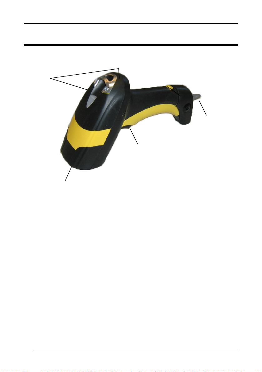
Laser Output
Window
Cable Connector
LEDs
Trigger
GENERAL VIEW
Figure A – WLS8600 Series Reader
WLS8600 READER
iv
Page 7

INTRODUCTION
1 INTRODUCTION
Wasp Barcode Technologies renews its range of industrial laser scanners introducing
the WLS8600 family. Robustness and ergonomics remain unsurpassed: clearly
audible beeper and bright "good read" LEDs for areas where noise levels are
normally high; the aim mode, which helps point to the right code, has now been
extended to the whole family. Optical parts are completely suspended on shock
absorbers and a careful choice of the body materials, such as the co-molded rubber,
protect the WLS8600 from damage due to "falls".
New enhanced architecture, based on an M16 high-speed microprocessor, enables
exceptional performance for promptness and reading speed of standard codes as
well as the ability to read poorly printed and damaged codes. Puzzle Solver
Technology™ adds further strength to the powerful engine of the WLS8600.
Your WLS8600 reader is supplied with its own Quick Reference Guide, which
provides connection, diagrams, reading diagrams, basic application parameter
settings, default values, and specific technical features. You can use either the Quick
Reference Guide or this Manual for initial configuration in order to set the default
values and select the interface for your application. This manual provides all the
necessary information for complete mechanical installation and system software
configuration.
1
Page 8
WLS8600
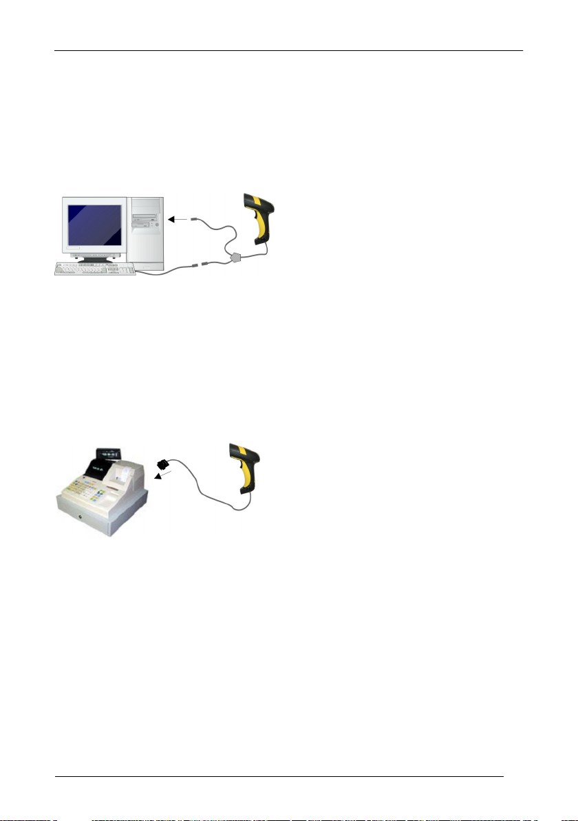
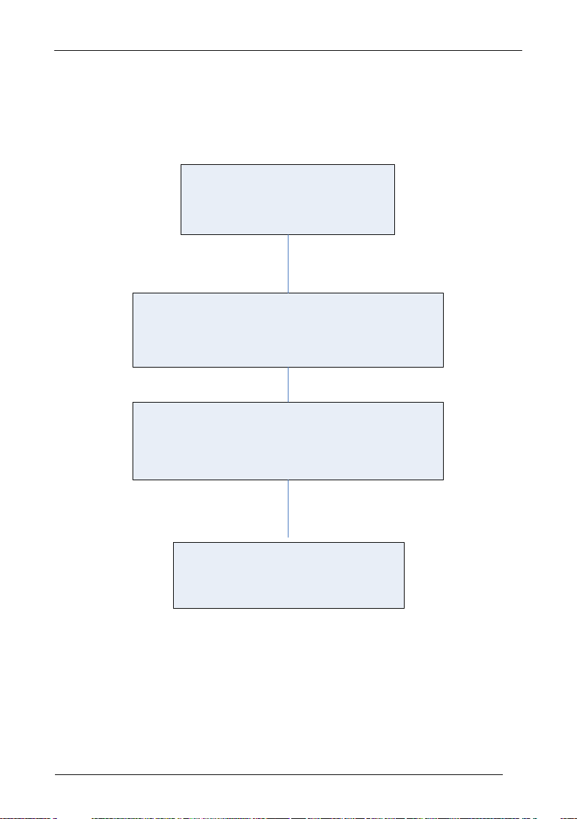
2 INSTALLATION
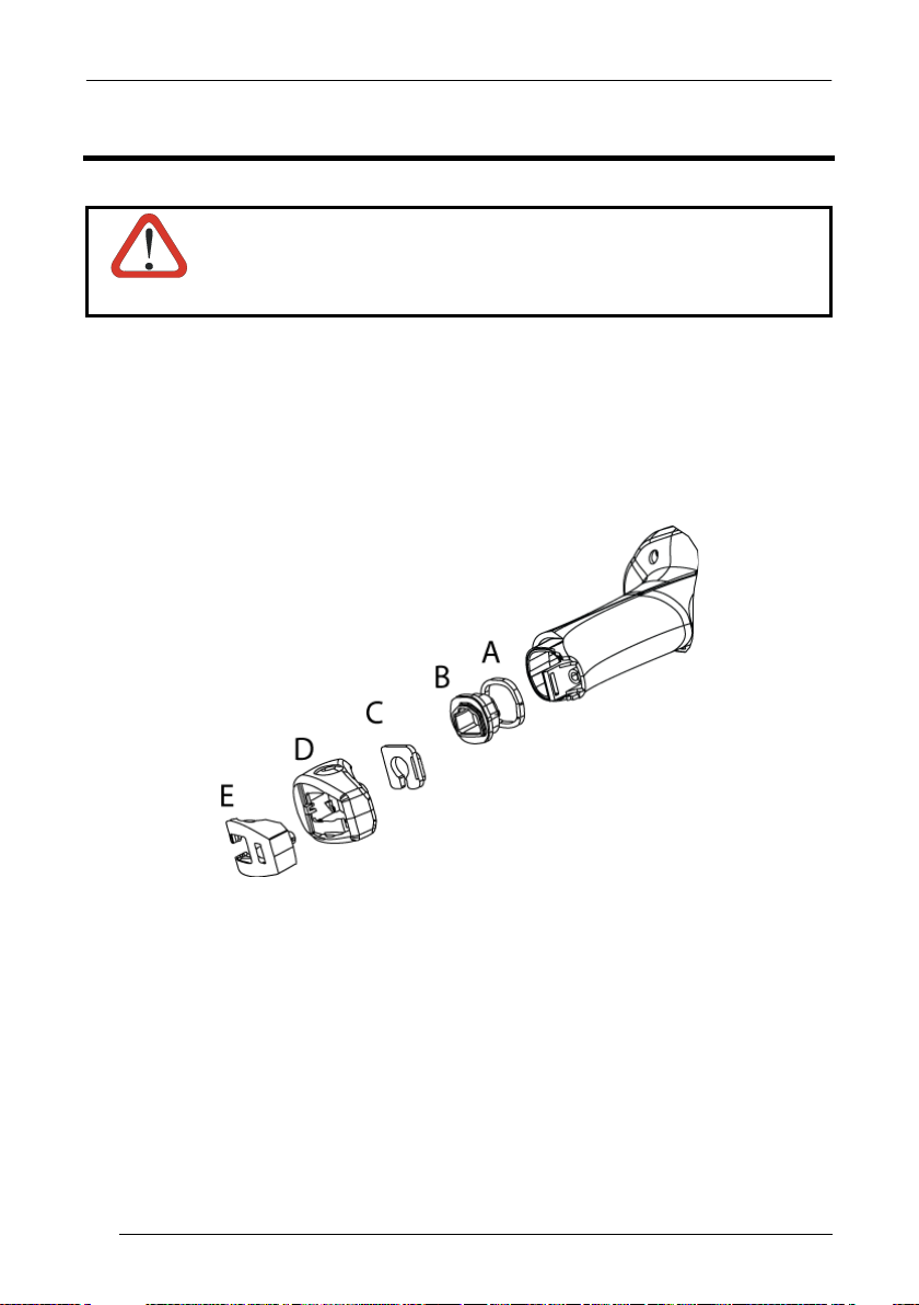
Connections should always be made with power OFF!
CAUTION
2.1 WLS8600 INTERFACE CABLE CONNECTIONS
The WLS8600 reader incorporates a multi-standard interface, which can be connected
to a Host by plugging the correct interface cable into the connector and closing the
cable cover.
A. Rubber gasket
B. Plastic boot
C. Cable spacer
D. Cover
E. Strain relief
2
Page 9
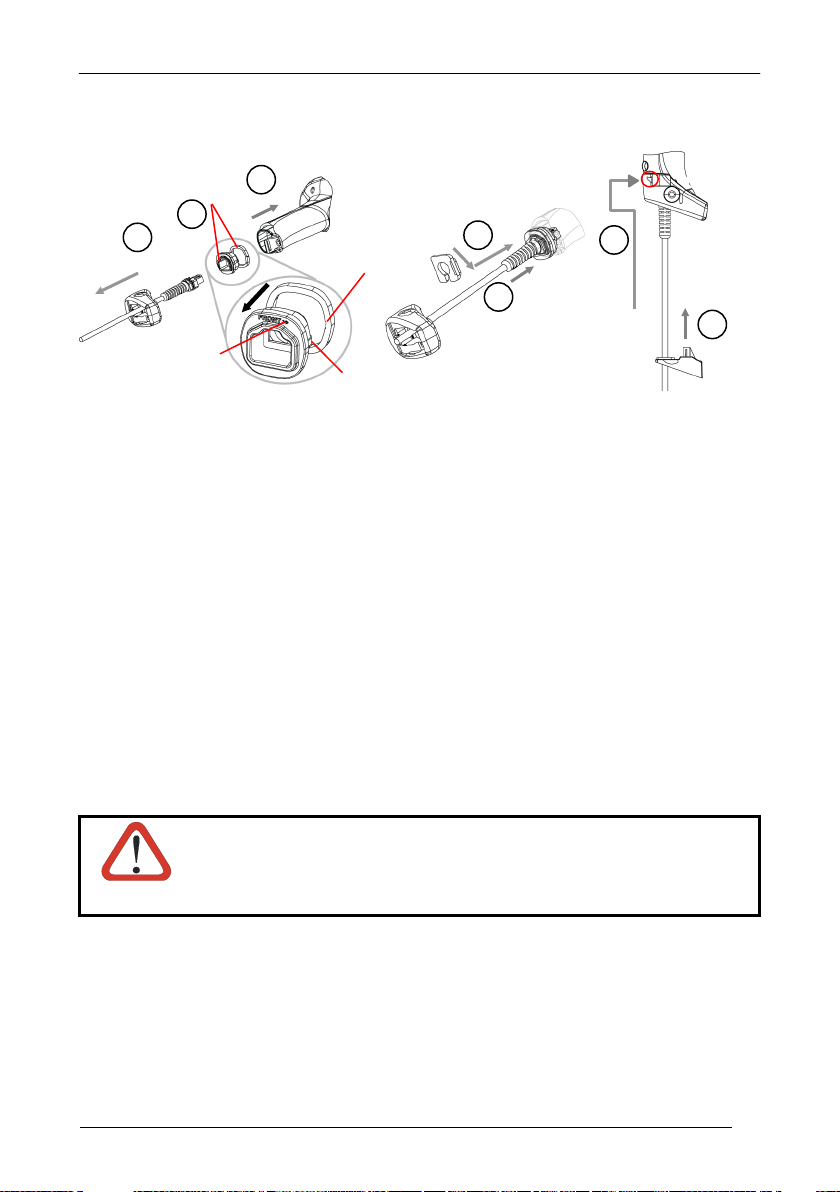
Follow the given procedure for correct cable insertion:
Align
1
2 3 4 5 6
7
Notch
Tab
Arrow
INSTALLATION
Slip the cover over the cable.
Push the plastic boot into the rubber gasket. Take care that the tab on the plastic
boot is aligned with the notch in the rubber gasket.
Push the plastic boot and gasket into the handle. Ensure that the “Front” marking
on the plastic boot is facing out, with the arrow pointing towards the front of the
scanner.
Insert the cable into the socket of the plastic boot.
Insert the cable spacer into the cable wire and slide it towards the handle.
Push the cover along the cable towards the reader, and hook it over the yellow
“tooth”.
Insert the strain relief into the cover and tighten the screw to fix the whole
assembly to the reader handle.
Connections should always be made with power OFF!
CAUTION
3
Page 10
WLS8600
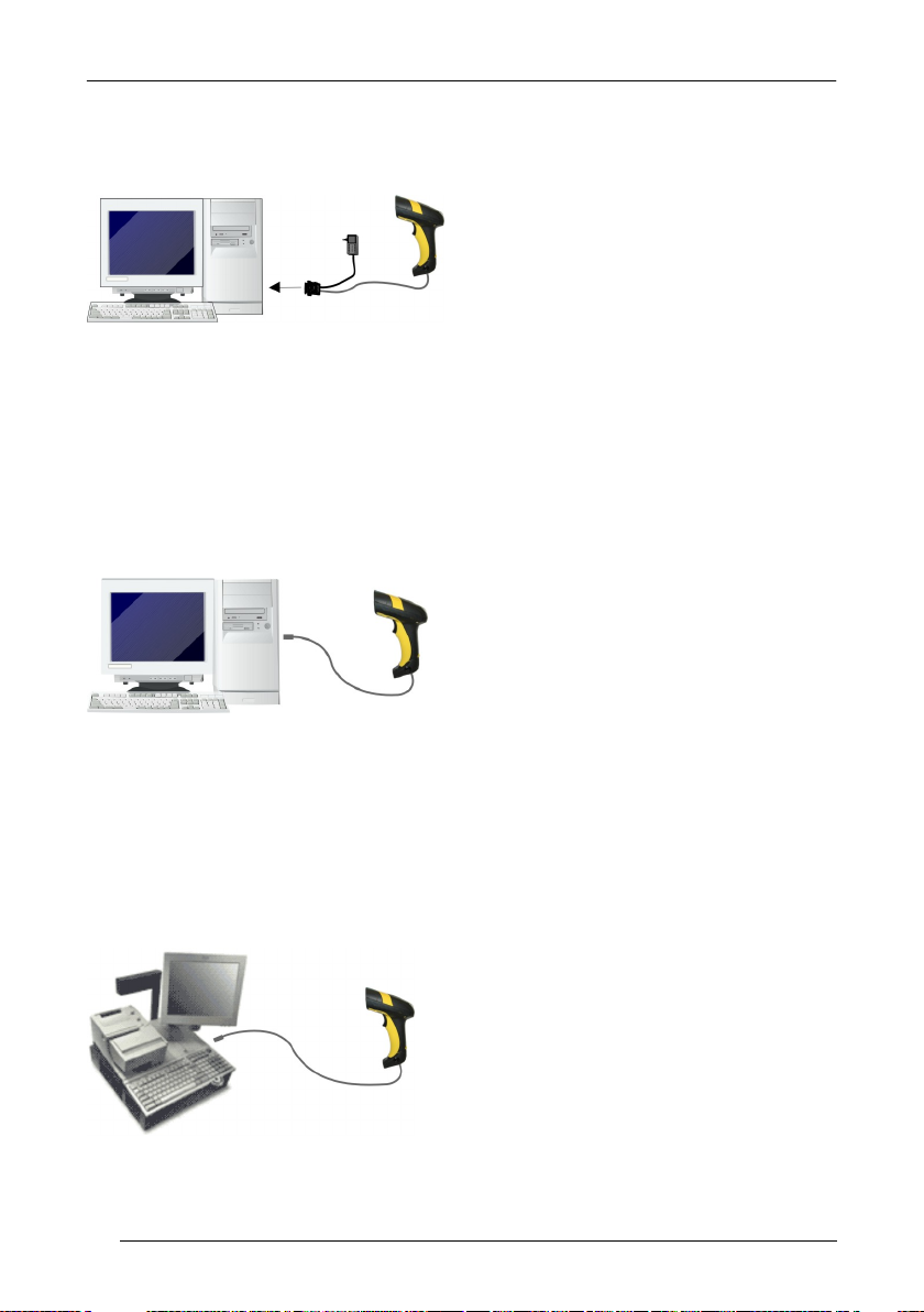
2.2 RS-232 CONNECTION
2.3 USB
2.4 IBM USB POS
4
Page 11
2.5 WEDGE CONNECTION
INSTALLATION
2.6 PEN EMULATION CONNECTION
5
Page 12

WLS8600
3 CONFIGURATION
3.1 CONFIGURATION METHODS
3.1.1 Reading Configuration Barcodes
This manual can be used for complete setup and configuration of your reader by
following the setup procedures in this chapter (see par. 3.2 for an overview).
If you wish to change the default settings, this manual provides complete
configuration of your reader in an easy way.
To configure your reader:
1) Open the folded page in Appendix C with the hex-numeric table and keep it
open during the device configuration.
2) Read the Enter Configuration code ONCE, available at the top of each page
of configuration.
3) Modify the desired parameters in one or more sections following the
procedures given for each group.
4) Read the Exit and Save Configuration code ONCE, available at the top of
each page of configuration.
Reference notes describing the operation of the more complex parameters are given
in chapter 0.
3.1.2 Copy Command
A previously configured device (Master), can be used to send its configuration directly
to other devices of the same type (Slaves). The particular procedure for each device is
given in par. 4.11.
3.1.3 Sending Configuration Strings from Host
An alternative configuration method is provided in Appendix A using the RS-232
interface. This method is particularly useful when many devices need to be
configured with the same settings. Batch files containing the desired parameter
settings can be prepared to configure devices quickly and easily.
6
Page 13
CONFIGURATION
BEGIN SETUP
Follow the procedure indicated
below.
1.
Restore default parameters
Scan the Restore Default barcode at section 3.3,
WLS8600 Setup.
2. Scan the interface code
Go to section 3.4, Interface Selection and choose
the appropriate barcode for your application.
END SETUP
Your reader is now ready to read
barcodes using the default settings.
3.2 SETUP PROCEDURES
For WLS8600 Series readers, follow the setup procedures in pars. 3.3, and 3.4.
Proceed as shown in the following diagram:
7
Page 14

WLS8600
1.
Read the restore default parameters code below.
Restore WLS8600 Default
Ì$+$*oÎ
After reading the above code, go to par. 3.4 Interface Selection.
3.3 WLS8600 SETUP
8
Page 15

3.4 INTERFACE SELECTION
Nixdorf Mode A
Ì$+CM2EC0$->Î
Ì$+CM1$-ÈÎ
Ì$+CM0$-ÃÎ
Read the interface selection code for your application.
RS-232
Standard
Ì$+CP0$-$Î
POS TERMINALS
CONFIGURATION
ICL Mode
For POS terminal default settings refer to par. 4.12.
PEN
Ì$+CP6$-BÎ
Fujitsu
9
Page 16

WLS8600
IBM AT or PS/2 PCs
Ì$+CP500$-aÎ
Ì$+CP503$-vÎ
Ì$+CP505$-ÈÎ
Ì$+CP506$-$Î
Ì$+CP504$-}Î
make-only keyboard
Ì$+CP502$-oÎ
Ì$+CP501$-hÎ
advanced keyboard
Ì$+FK1$-ÉÎ
Ì$+FK0$-ÄÎ
PC Notebook
IBM Terminal 3153
IBM XT
IBM SURE1
IBM Terminals 31xx, 32xx, 34xx, 37xx:
WEDGE
To select the interface for these IBM Terminals, read the correct KEY TRANSMISSION code.
Select the KEYBOARD TYPE if necessary (default = advanced keyboard).
KEY TRANSMISSION MODE
10
make-break keyboard
KEYBOARD TYPE
typewriter keyboard
Page 17

CONFIGURATION
IBM AT - ALT mode
Ì$+CP507$-+Î
Ì$+CP508$-2Î
ANSI Keyboard
Ì$+CP509$-9Î
Ì$+CP510$-gÎ
Ì$+CP511$-nÎ
Ì$+CP514$-ÇÎ
WEDGE (CONTINUED)
ALT MODE
The ALT-mode selection allows barcodes sent to the PC to be interpreted correctly
independently from the Keyboard Nationality used. You do not need to make a
Keyboard Nationality selection.
(default = Num Lock Unchanged). Make sure the Num Lock key on your
keyboard is ON.
WYSE TERMINALS
PC Notebook - ALT mode
PC Keyboard
ASCII Keyboard
VT220 style Keyboard
DIGITAL TERMINALS
VT2xx/VT3xx/VT4xx
Ì$+CP512$-uÎ
11
Page 18
WLS8600
Windows 98 (and later)
IBM POS for Windows
Mac OS 8.0 (and later)
4690 Operating System
Connect device to
Host
Select desired USB
interface code
(USB-KBD is default)
Read test codes.
Device is READY
Load drivers
(if requested)
Load drivers
(if requested)
reader LED blinks
reader LED off - BEEP OK
First Start-Up
1
2
3.5 USB READER CONFIGURATION
The USB interface is compatible with the following Operating Systems:
USB Start-up
As with all USB devices, upon connection, the Host performs several checks by
communicating with the device. During this phase normal operations are suspended
(the LED on the WLS8600 reader blinks). Two basic conditions must be met before
the device is ready, the correct USB driver must be loaded and sufficient power must
be supplied to the reader.
For all systems, the correct USB driver for the
default USB-KBD interface is included in the Host
Operating System and will either be loaded
automatically or will be suggested by the O.S.
and should therefore be selected from the dialog
box (the first time only).
Normally the Host supplies sufficient power to
the device and the start-up phase ends
correctly. (The reader's LED stops blinking and
the reader emits the beep OK signal).
In rare cases, if the Host does not supply
sufficient power to the device, a dialog box will
appear on the Host and the device will be
blocked (the reader's LED continues blinking). In
this case, disconnect the USB device cable at the
Host (the reader's LED stops blinking), and then
try a different USB port as indicated by the
Operating System message. (The device emits
the beep OK signal. You can now read codes).
At this point you can read the USB interface configuration code according to your
application. Load drivers from the O.S. (if requested). When configuring the
USB-COM interface, the relevant files and drivers must be installed from the USB
Device Installation software. Contact WASP Technical Support for more information.
The device is ready. Successive start-ups will automatically recognize the previously
loaded drivers.
12
Page 19

CONFIGURATION
USB
USB-KBD
Ì$+UA03$-:Î
USB-KBD-ALT-MODE
Ì$+UA04$-@Î
USB-KBD-APPLE
Ì$+UA05$-FÎ
USB-COM*
Ì$+UA02$-4Î
USB-IBM-Table Top
Ì$+UA00$-(Î
USB-IBM-Hand Held
Ì$+UA01$-.Î
* When configuring USB-COM, the relevant files and drivers must be installed from
the USB Device Installation software. Contact WASP Technical Support for more
information.
13
Page 20

WLS8600
3.6 CHANGING DEFAULT SETTINGS
Once your reader is setup, you can change the default parameters to meet your
application needs. Refer to the preceding paragraphs for initial configuration in order
to set the default values and select the interface for your application.
In this manual, the configuration parameters are divided into logical groups making it
easy to find the desired function based on its reference group.
RS-232
USB
WEDGE
PEN EMULATION
DATA FORMAT parameters regard the messages sent to the Host system for all
interfaces except Pen Emulation.
POWER SAVE manages overall current consumption in the reading device.
READING PARAMETERS control various operating modes and indicator status
functioning.
DECODING PARAMETERS maintain correct barcode decoding in certain special
reading conditions.
CODE SELECTION parameters allow configuration of a personalized mix of codes,
code families and their options.
ADVANCED FORMATTING PARAMETERS allow code concatenation and
advanced formatting of messages towards the Host. It cannot be used with Pen
Emulation connections.
14
Page 21

RS-232 PARAMETERS
B
D
S
ACK/N
F
RX T
S
= Default value
All WLS8600 Series readers
AUD RATE
PARITY
ATA BITS
TOP BITS
HANDSHAKING
ACK PROTOCOL
IFO
INTER-CHARACTER DELAY
IMEOUT
ERIAL TRIGGER LOCK
1. Read the Enter Configuration code ONCE, available at the top of each page.
2. Read configuration codes from the desired groups.
3. Read the Exit and Save Configuration code ONCE, available at the top of
each page.
= Read the code and follow the procedure given
15
Page 22

Enter Configuration
Exit and Save Configuration
Ì$+;Î
RS-232
Ì$-?Î
300 baud
ÌCD1XÎ
ÌCD2[Î
ÌCD3^Î
ÌCD4aÎ
ÌCD5dÎ
ÌCD6gÎ
ÌCD7jÎ
ÌCD8mÎ
none
ÌCC0SÎ
ÌCC1VÎ
ÌCC2YÎ
BAUD RATE
1200 baud
4800 baud
19200 baud
600 baud
2400 baud
9600 baud
38400 baud
PARITY
16
odd parity
even parity
Page 23

Enter Configuration
Exit and Save Configuration
Ì$+;Î
RS-232
Ì$-?Î
7 bits
ÌCA0OÎ
ÌCA1RÎ
ÌCA2UÎ
1 stop bit
ÌCB0QÎ
ÌCB1TÎ
disable
ÌCE0WÎ
ÌCE1ZÎ
ÌCE2]Î
ÌCE3`Î
DATA BITS
9 bits
8 bits
STOP BITS
2 stop bits
HANDSHAKING
hardware (RTS/CTS)
software (XON/XOFF)
See par. 4.1.1 for details.
RTS always ON
17
Page 24

Enter Configuration
Exit and Save Configuration
Ì$+;Î
RS-232
Ì$-?Î
disable
ÌER0sÎ
ÌER1vÎ
disable
ÌEC0UÎ
ÌEC1XÎ
ACK/NACK PROTOCOL
See par. 4.1.2 for details.
enable
FIFO
See par. 4.1.3 for details.
enable
INTER-CHARACTER DELAY
delay between characters transmitted to Host
ÌCK3Î
Read 2 numbers from the table where:
00 = DELAY disabled
01-99 = DELAY from 1 to 99 milliseconds
delay disabled
18
Page 25

Enter Configuration
Exit and Save Configuration
Ì$+;Î
RS-232
Ì$-?Î
RX TIMEOUT
timeout control in reception from Host
ÌCL5Î
Read 2 numbers from the table where:
00 = TIMEOUT disabled
01-99 = TIMEOUT from .1 to 9.9 seconds
rx timeout 5 seconds
See par. 4.1.4 for details.
SERIAL TRIGGER LOCK
disabled
ÌCR0qÎ
enable and select characters
ÌCR1tÎ
Read 2 characters from the Hex/Numeric table in the range 00-FE where:
− First Character enables device trigger
− Second Character inhibits device trigger until the first character is received again.
19
Page 26

= Default value
USB PARAMETERS
Handshaking, Ack/Nack protocol, FIFO,
Inter-character delay, Rx timeout, Serial
Keyboard nationality, FIFO, Inter-character
delay, Inter-code delay, USB keyboard
No parameter selection required.
USB-COM
trigger lock
USB-KBD
speed
USB-IBM
1. Read the Enter Configuration code ONCE, available at the top of each page.
2. Read configuration codes from the desired groups.
3. Read the Exit and Save Configuration code ONCE, available at the top of
20
= Read the code and follow the procedure given
each page.
Page 27

Enter Configuration
Exit and Save Configuration
Ì$+;Î
USB-COM
Ì$-?Î
disable
ÌCE0WÎ
ÌCE1ZÎ
ÌCE2]Î
ÌCE3`Î
disable
ÌER0sÎ
ÌER1vÎ
disable
ÌEC0UÎ
ÌEC1XÎ
HANDSHAKING
software (XON/XOFF)
See par. 4.1.1 for details.
ACK/NACK PROTOCOL
See par. 4.1.2 for details.
FIFO
hardware (RTS/CTS)
RTS always ON
enable
See par. 4.1.3 for details.
enable
21
Page 28

Enter Configuration
Exit and Save Configuration
Ì$+;Î
USB-COM
Ì$-?Î
INTER-CHARACTER DELAY
delay between characters transmitted to Host
ÌCK3Î
Read 2 numbers from the table where:
00 = DELAY disabled
01-99 = DELAY from 1 to 99 milliseconds
delay disabled
RX TIMEOUT
timeout control in reception from Host
ÌCL5Î
Read 2 numbers from the table where:
00 = TIMEOUT disabled
01-99 = TIMEOUT from .1 to 9.9 seconds
rx timeout 5 seconds
See par. 4.1.4 for details.
SERIAL TRIGGER LOCK
disabled
Read 2 characters from the Hex/Numeric table in the range 00-FE where:
− First Character enables device trigger
− Second Character inhibits device trigger until the first character is received again.
22
ÌCR0qÎ
enable and select characters
ÌCR1tÎ
Page 29

Enter ConfiguratioN
Exit and Save Configuration
Ì$+;Î
USB-KBD
Ì$-?Î
KEYBOARD NATIONALITY
Belgian
ÌFJ7yÎ
ÌFJ4pÎ
ÌFJ2jÎ
ÌFJ3mÎ
ÌFJ1gÎ
ÌFJ6vÎ
ÌFJ5sÎ
ÌFJ0dÎ
Not Available for USB-KBD-ALT-MODE Interface
This parameter default value is restored through the Interface Selection code and not Restore
Default.
French
Italian
Swedish
English (UK)
German
Spanish
USA
23
Page 30

Enter Configuration
Exit and Save Configuration
Ì$+;Î
USB-KBD
Ì$-?Î
Japanese
ÌFJ8|Î
ÌFJ9ÃÎ
ÌFJA0Î
ÌFJB3Î
ÌFJC6Î
ÌFJD9Î
ÌFJE<Î
disable
ÌEC0UÎ
ÌEC1XÎ
The Japanese and Eastern Block Keyboard Nationality selections are valid only for IBM AT
compatible PCs.
Russian (Cyrillic)
Slovenian, Croatian,
Serbian (Latin)
Czech Republic
Russian (Latin)
Hungarian
Romanian
FIFO
24
See par. 4.1.3 for details.
enable
Page 31

Enter ConfiguratioN
Exit and Save Configuration
Ì$+;Î
USB-KBD
Ì$-?Î
Normal
ÌUT10cÎ
ÌUT01dÎ
INTER-CHARACTER DELAY
delay between characters transmitted to Host
ÌCK3Î
Read 2 numbers from the table where:
00 = DELAY disabled
01-99 = DELAY from 1 to 99 milliseconds
delay disabled
INTER-CODE DELAY
delay between codes transmitted to Host
ÌFG.Î
Read 2 numbers from the table where:
00 = DELAY disabled
01-99 = DELAY from 1 to 99 seconds
delay disabled
USB KEYBOARD SPEED
Fast
25
Page 32

K
A
I
I
= Default value
WEDGE PARAMETERS
EYBOARD NATIONALITY
CAPS LOCK
CAPS LOCK
UTO-RECOGNITION
NUM LOCK
NTER-CHARACTER DELAY
NTER-CODE DELAY
KEYBOARD SETTING
WEDGE CONTROL CHARACTER
EMULATION
1. Read the Enter Configuration code ONCE, available at the top of each page.
2. Read configuration codes from the desired groups.
3. Read the Exit and Save Configuration code ONCE, available at the top of
26
each page.
= Read the code and follow the procedure given
Page 33

Enter Configuration
Exit and Save Configuration
Ì$+;Î
WEDGE
Ì$-?Î
Belgian
ÌFJ7yÎ
ÌFJ4pÎ
ÌFJ2jÎ
ÌFJ3mÎ
ÌFJ1gÎ
ÌFJ6vÎ
ÌFJ5sÎ
ÌFJ0dÎ
KEYBOARD NATIONALITY
French
Italian
Swedish
English (UK)
German
Spanish
USA
27
Page 34

Enter Configuration
Exit and Save Configuration
Ì$+;Î
WEDGE
Ì$-?Î
Japanese
ÌFJ8|Î
ÌFJ9ÃÎ
ÌFJA0Î
ÌFJB3Î
ÌFJC6Î
ÌFJD9Î
ÌFJE<Î
caps lock OFF
ÌFE0ZÎ
ÌFE1]Î
The Japanese and Eastern Block Keyboard Nationality selections are valid only for IBM AT
compatible PCs.
Russian (Cyrillic)
Slovenian, Croatian,
Serbian (Latin)
Czech Republic
Russian (Latin)
Hungarian
Romanian
CAPS LOCK
NOTE: Caps lock manual configuration is ignored when Caps Lock Auto-Recognition is
enabled. For PC Notebook interface selections, the caps lock status is automatically
recognized; therefore this command is not necessary.
28
Select the appropriate code to match your keyboard caps lock status.
caps lock ON
Page 35

Enter Configuration
Exit and Save Configuration
Ì$+;Î
WEDGE
Ì$-?Î
CAPS LOCK AUTO-RECOGNITION (IBM AT COMPATIBLE ONLY)
disable
ÌFP0pÎ
ÌFP1sÎ
toggle num lock
ÌFL1kÎ
ÌFL0hÎ
enable
NUM LOCK
This selection is used together with the Alt Mode interface selection for AT or Notebook PCs.
It changes the way the Alt Mode procedure is executed; therefore it should be set as follows:
• if your keyboard Num Lock is normally on use num lock unchanged
• if your keyboard Num Lock is normally off use toggle num lock
In this way the device will execute the Alt Mode procedure correctly for your application.
num lock unchanged
INTER-CHARACTER DELAY
delay between characters transmitted to Host
ÌCK3Î
Read 2 numbers from the table where:
00 = DELAY disabled
01-99 = DELAY from 1 to 99 milliseconds
delay disabled
29
Page 36

Enter Configuration
Exit and Save Configuration
Ì$+;Î
WEDGE
Ì$-?Î
INTER-CODE DELAY
delay between codes transmitted to Host
ALPHANUMERIC KEYBOARD SETTING
The device (reader or cradle) can be used with terminals or PCs with various keyboard types
and nationalities through a simple keyboard setting procedure.
The type of computer or terminal must be selected before activating the keyboard setting
command.
Keyboard setting consists of communicating to the device how to send data corresponding to
the keyboard used in the application. The keys must be set in a specific order.
Press and release a key to set it.
Some characters may require more than one key pressed simultaneously during normal use
(refer to the manual of your PC or terminal for keyboard use). The exact sequence must be
indicated to the reader in this case pressing and releasing the different keys.
Example:
If one has to press the "Shift" and "4" keys simultaneously on the keyboard to transmit the
character "$" to the video, to set the "$", press and release "Shift" then press and release "4".
Each pressed and released key must generate an acoustic signal on the device;
otherwise repress the key. Never press more than one key at the same time, even if this
corresponds to the normal use of your keyboard.
Press "Backspace" to correct a wrong key entry. In this case the device emits 2 beeps.
NOTE: "CAPS LOCK" and "NUM LOCK" must be off before starting the keyboard setting
procedure. "SHIFT" must be repressed for each character and cannot be substituted by "CAPS
LOCK".
Read 2 numbers from the table where:
00 = DELAY disabled
01-99 = DELAY from 1 to 99 seconds
delay disabled
KEYBOARD SETTING
setting the alphanumeric keyboard
ÌFG.Î
Read the code above.
Press the keys shown in the following table according to their numerical order.
30
ÌFB0TÎ
Page 37

WEDGE
Some ASCII characters may be missing as this depends on the type of keyboard: these are
01 : Shift
02 : Alt
03 : Ctrl
04 : Backspace
05 : SPACE
28 : 7
51 : N
06 : !
29 : 8
52 : O
07 : "
30 : 9
53 : P
08 : #
31 : :
54 : Q
09 : $
32 : ;
55 : R
10 : %
33 : <
56 : S
11 : &
34 : =
57 : T
12 : '
35 : >
58 : U
13 : (
36 : ?
59 : V
14 : )
37 : @
60 : W
15 : *
38 : A
61 : X
16 : +
39 : B
62 : Y
17 : ,
40 : C
63 : Z
18 : -
41 : D
64 : [
19 : .
42 : E
65 : \
20 : /
43 : F
66 : ]
21 : 0
44 : G
67 : ^
22 : 1
45 : H
68 : _ (underscore)
23 : 2
46 : I
69 : `
24 : 3
47 : J
70 : {
25 : 4
48 : K
71 : |
26 : 5
49 : L
72 : }
27 : 6
50 : M
73 : ~
74 : DEL
generally particular characters relative to the various national symbologies. In this case:
• The first 4 characters (Shift, Alt, Ctrl, and Backspace) can only be substituted with
keys not used, or substituted with each other.
• characters can be substituted with other single symbols (e.g. "SPACE") even if not
included in the barcode set used.
• characters can be substituted with others corresponding to your keyboard.
The device signals the end of the procedure with 2 beeps indicating the keys have been
registered.
31
Page 38

Enter Configuration
Exit and Save Configuration
Ì$+;Î
WEDGE
Ì$-?Î
Ctrl + Shift + Key
ÌFO0nÎ
ÌFO1qÎ
CONTROL CHARACTER EMULATION
Ctrl + Key
32
Page 39

PEN EMULATION
O
M
O
O
I
= Default value
PERATING MODE
INIMUM OUTPUT PULSE
CONVERSION TO CODE 39
VERFLOW
UTPUT LEVEL
IDLE LEVEL
NTER-BLOCK DELAY
1. Read the Enter Configuration code ONCE, available at the top of each page.
2. Read configuration codes from the desired groups.
3. Read the Exit and Save Configuration code ONCE, available at the top of
each page.
33
Page 40

PEN EMULATION
The operating mode parameters are complete commands and do not require reading the
Enter and Exit configuration codes.
OPERATING MODE
interpret mode
Ì$]8Î
Interprets commands without sending them to the decoder.
transparent mode
34
Ì$[4Î
Sends commands to the decoder without interpreting them.
Page 41

Enter Configuration
Exit and Save Configuration
Ì$+;Î
PEN EMULATION
Ì$-?Î
low resolution code
emulation
high resolution code
emulation
ÌDG0\Î
ÌDG1_Î
ÌDG2bÎ
ÌDG3eÎ
ÌDG4hÎ
ÌDG5kÎ
MINIMUM OUTPUT PULSE
200 µs
600 µs
400 µs
800 µs
1 ms
1.2 ms
See par. 4.2.1 for details.
35
Page 42

Enter Configuration
Exit and Save Configuration
Ì$+;Î
PEN EMULATION
Ì$-?Î
CONVERSION TO CODE 39
disable conversion to Code 39
ÌDA0PÎ
format.
ÌDA1SÎ
Code 39 format.
enable conversion to Code 39
ÌDA1SÎ
39 format.
ÌDA0PÎ
128 format.
narrow
ÌDH0^Î
ÌDH1aÎ
ÌDH2dÎ
Transmits codes in their original
enable conversion to Code 39
Converts codes read into
CONVERSION TO CODE 39 AND CODE 128
Converts codes read into Code
wide
See par. 4.2.2 for details.
enable conversion to Code 128
Converts codes read into Code
See par. 4.2.2 for details.
OVERFLOW
medium
36
See par. 4.2.3 for details.
Page 43

Enter Configuration
Exit and Save Configuration
Ì$+;Î
PEN EMULATION
Ì$-?Î
normal
ÌDD0VÎ
ÌDD1YÎ
(white = logic level 1)
normal
ÌDE0XÎ
ÌDE1[Î
(white level)
(white = logic level 0)
(black level)
OUTPUT LEVEL
inverted
See par. 4.2.4 for details.
IDLE LEVEL
inverted
See par. 4.2.4 for details.
INTER-BLOCK DELAY
delay between character blocks transmitted to Host
ÌCK3Î
Read 2 numbers from the table where:
00 = DELAY disabled
01-99 = DELAY from .1 to 9.9 seconds
delay disabled
See par. 4.2.5 for details.
37
Page 44

DATA FORMAT
C
H
S
F
C
C
= Default value
NOT FOR PEN INTERFACES
CODE IDENTIFIER
USTOM CODE IDENTIFIER
EADER
TERMINATOR
PECIAL KEYS
IELD ADJUSTMENT
FIELD ADJ. CHARACTER
ODE LENGTH TX
HARACTER REPLACEMENT
1. Read the Enter Configuration code ONCE, available at the top of each page.
2. Read configuration codes from the desired groups.
= Read the code and follow the procedure given
3. Read the Exit and Save Configuration code ONCE, available at the top of
38
each page.
Page 45

DATA FORMAT
CODE IDENTIFIER TABLE
2/5 interleaved
] I y
N
2/5 industrial
] X y
P
2/5 normal 5 bars
] S y
O
2/5 matrix 3 bars
] X y
Q
EAN 8
] E 4
A
EAN 13
] E 0
B
UPC A
] X y
C
UPC E
] X y
D
EAN 8 with 2 ADD ON
] E 5
J
EAN 8 with 5 ADD ON
] E 6
K
EAN 13 with 2 ADD ON
] E 1
L
EAN 13 with 5 ADD ON
] E 2
M
UPC A with 2 ADD ON
] X y
F
UPC A with 5 ADD ON
] X y
G
UPC E with 2 ADD ON
] X y
H
UPC E with 5 ADD ON
] X y
I
Code 39
] A y
V
Code 39 Full ASCII
] A y
W
CODABAR
] F y
R
ABC CODABAR
] X y
S
Code 128
] C y
T
EAN 128
] C y
k
ISBT 128
] C4
f
Code 93
] G y
U
CIP/39
] X y
Y
CIP/HR
] X y
e
Code 32
] X y
X
MSI
] M y
Z
Code 11
] H y
b
Code 16K
] K 0
p
Code 49
] T y
q
GS1 DataBar™ Expanded Linear and Stacked
] e 0
t
GS1 DataBar Limited
] e 0
v
GS1 DataBar 14 Linear and Stacked
] e 0
u
CODE
AIM
STAN DARD
WAS P STANDARD Custom
• AIM standard identifiers are not defined for all codes: the X identifier is assigned to the
code for which the standard is not defined. The y value depends on the selected options
(check digit tested or not, check digit tx or not, etc.).
• When customizing the Wasp Standard code identifiers, 1 or 2 identifier characters can be
defined for each code type. If only 1 identifier character is required, the second character
must be selected as FF (disabled).
• The code identifier can be singly disabled for any code by simply selecting FF as the first
identifier character.
• Write in the Custom character identifiers in the table above for your records.
39
Page 46

Enter Configuration
Exit and Save Configuration
Ì$+;Î
DATA FORMAT
Ì$-?Î
disable
ÌEB0SÎ
ÌEB1VÎ
ÌEB2YÎ
ÌEB3\Î
define custom code identifier(s)
Code 39
ÌEH/Î
ÌVWÎ
CODE IDENTIFIER
AIM standard
Wasp standard
custom
CUSTOM CODE IDENTIFIER
define custom code identifier(s)
ÌEH/Î
Read the above code.
(Code Identifiers default to Wasp standard, see table on previous page).
Select the code type from the code table in Appendix
change.
You can define 1 or 2 identifier characters for each code type. If only 1 identifier character is
required, the second character must be selected as FF (disabled). Read the hexadecimal
value corresponding to the character(s) you want to define as identifiers for the code
selected in step : valid characters are in the range 00-FD.
Example: To define Code 39 Code Identifier = @
B for the identifier you want to
Read
40
+
40
+
FF
+
Page 47

Enter Configuration
Exit and Save Configuration
Ì$+;Î
DATA FORMAT
Ì$-?Î
no header
ÌEA00*Î
ÌEA01.Î
ÌEA022Î
ÌEA036Î
ÌEA04:Î
ÌEA05>Î
ÌEA06BÎ
ÌEA07FÎ
ÌEA08JÎ
four character header
two character header
four character header
six character header
HEADER
one character header
three character header
five character header
After selecting one of the desired Header codes, read the character(s) from the HEX table.
Valid characters are in the range 00-FE. For Wedge and USB-KBD interfaces, it is also possible
to read the Special Key(s) on page 42.
Example:
For more details see par. 4.3.1 and par. 4.3.2.
seven character header
eight character header
+ 41 + 42 + 43 + 44 = Header ABCD
41
Page 48

Enter Configuration
Exit and Save Configuration
Ì$+;Î
DATA FORMAT
Ì$-?Î
no terminator
ÌEA10-Î
ÌEA111Î
ÌEA125Î
ÌEA139Î
ÌEA14=Î
ÌEA15AÎ
ÌEA16EÎ
ÌEA17IÎ
ÌEA18MÎ
two character terminator
TERMINATOR
one character terminator
two character terminator
three character terminator
four character terminator
five character terminator
six character terminator
After selecting one of the desired Header codes, read the character(s) from the HEX table.
Valid characters are in the range 00-FE. For Wedge and USB-KBD interfaces, it is also possible
to read the Special Key(s) on page 42.
Example:
For more details see par. 4.3.1 and par. 4.3.2.
42
eight character terminator
seven character terminator
+ 0D + 0A = Terminator CR LF
SPECIAL KEYS
Page 49

Enter Configuration
Exit and Save Configuration
Ì$+;Î
DATA FORMAT
Ì$-?Î
NOTE
Special Key 1
Ì9CÄÎ
Ì9DÆÎ
Ì9EÈÎ
Ì9FÊÎ
ÌA0bÎ
Available only for Wedge IBM AT-PS/2 and USB-KBD Interfaces
It is necessary to define each Special Key by following the procedure given in
par. 4.3.2.
Select one or more of the following Special Keys according to your needs.
Special Key 3
Special Key 2
Special Key 4
Special Key 5
43
Page 50

Enter Configuration
Exit and Save Configuration
Ì$+;Î
DATA FORMAT
Ì$-?Î
FIELD ADJUSTMENT
enable field adjustment
ÌEF+Î
right addition
Ì01Î
Ì12Î
Ì23Î
Ì34Î
enable field adjustment
Code 39
right addition
ÌEF+Î
ÌVWÎ
Ì01Î
disable field adjustment
ÌEF0[Î
Field adjustment allows a number of characters n, to be added to or subtracted from the
barcode read. The adjustment can be different for each enabled code type. To define the field
adjustment:
Read the enable field adjustment code:
Select the code type from the Code Identifier Table in Appendix B.
Select the type of adjustment to perform:
right deletion
Read a number in the range 01 - 32 from the Hex/Numeric Table to define how many
characters to add or delete:
Conditions:
• Adjustment is only performed on the barcode data, the Code Identifier and Code Length
Transmission fields are not modified by the field adjustment parameter.
• If the field setting would subtract more characters than exist in the barcode, the subtraction
will take place only to code length 0.
• You can set up to a maximum of 10 different field adjustments on the same barcode family
or on different barcode families.
Example: To add 4 characters to the right of Standard Code 39 Codes:
Read
+
+
left addition
left deletion
04
+
44
Page 51

Enter Configuration
Exit and Save Configuration
Ì$+;Î
DATA FORMAT
Ì$-?Î
FIELD ADJUSTMENT CHARACTER
field adjustment character
ÌEG-Î
field adjustment character
Read the field adjustment character code:
Read the hexadecimal value corresponding to the character you want to use for field
adjustment. Valid characters are in the range 00-FE. For Wedge and USB-KBD interfaces, it
is also possible to read the Special Key(s) on page 42.
Example:
To define the field adjustment character = A:
Read
+ 41
CODE LENGTH TX
code length not transmitted
ÌEE0YÎ
code length transmitted in variable-digit format
ÌEE1\Î
code length transmitted in fixed 4-digit format
ÌEE2_Î
The code length is transmitted in the message after the Headers and Code Identifier characters.
The code length is calculated after performing any field adjustment operations.
45
Page 52

Enter Configuration
Exit and Save Configuration
Ì$+;Î
DATA FORMAT
Ì$-?Î
CHARACTER REPLACEMENT
first character replacement
ÌEO1pÎ
ÌEO2sÎ
ÌEO3vÎ
disable character replacement
ÌEO0mÎ
This parameter allows up to three characters to be replaced from the barcode read. These
substitutions are stored in memory. To define each character replacement:
Read one of the following character replacement codes:
second character replacement
third character replacement
From the Code Identifier Table in Appendix B, read the Code Identifier for the desired
code family.
0 = character replacement will be effective for all code families.
From the Hex/Numeric Table read two characters corresponding to the Hex value
(00-FE), which identifies the character to be replaced. For Wedge and USB-KBD
interfaces, it is also possible to read the Special Key(s) on page 42.
From the Hex/Numeric Table read two characters corresponding to the Hex value
(00-FE), which identifies the new character to replace. For Wedge and USB-KBD
interfaces, it is also possible to read the Special Key(s) on page 42.
FF = the character to be replaced will be substituted with no character, that is, it will be
removed from the code.
46
Page 53

Enter Configuration
Exit and Save Configuration
Ì$+;Î
DATA FORMAT
Ì$-?Î
ASCII characters corresponding to
the HEX value for character 0
ASCII characters corresponding
to the HEX value for character 1
ÌEO1pÎ
ÌVWÎ
second character
replacement
ASCII characters corresponding to
the HEX value for character A
ASCII characters corresponding
to the HEX value for character B
ÌEO2sÎ
ÌVWÎ
Example:
The following strings define:
1. First Character Replacement: substitution in Code 39 barcodes of all occurrences of the
0 character with the 1 character.
2. Second Character Replacement: substitution in Code 39 barcodes of all occurrences of
the A character with the B character.
first character replacement
For Code 39 codes containing the string "0123", the contents transmitted will be "1123".
For Code 39 codes containing the string "ABCD", the contents transmitted will be "BBCD".
Code 39
+
Code 39
+
+
+
30
41
+
+
31
42
47
Page 54

E
= Default value
POWER SAVE
SLEEP STATE
NTER SLEEP TIMEOUT
1. Read the Enter Configuration code ONCE, available at the top of each page.
2. Read configuration codes from the desired groups.
3. Read the Exit and Save Configuration code ONCE, available at the top of
48
= Read the code and follow the procedure given
each page.
Page 55

Enter Configuration
Exit and Save Configuration
Ì$+;Î
POWER SAVE
Ì$-?Î
disable
ÌBQ0nÎ
ÌBQ1qÎ
SLEEP STATE
enable
See par. 4.4.1 for details.
ENTER SLEEP TIMEOUT
enter sleep timeout
ÌBR@Î
Read 2 numbers in the range 00-99:
00 = Enter Sleep state immediately
01-99 = corresponds to a max. 9.9 sec. delay before entering the
Sleep state.
enter sleep timeout = 0.6 sec.
See par. 4.4.2 for details.
49
Page 56

READING PARAMETERS
T
T
T
R
B
B
G
= Default value
RIGGER TYPE
TRIGGER SIGNAL
RIGGER CLICK
RIGGER-OFF TIMEOUT
FLASH MODE
EADS PER CYCLE
SAFETY TIME
BEEPER INTENSITY
EEPER TONE
BEEPER TYPE
EEPER LENGTH
OOD READ SPOT DURATION
AIMING SYSTEM
1. Read the Enter Configuration code ONCE, available at the top of each page.
2. Read configuration codes from the desired groups.
3. Read the Exit and Save Configuration code ONCE, available at the top of
50
each page.
= Read the code and follow the procedure given
Page 57

Enter Configuration
Exit and Save Configuration
Ì$+;Î
READING PARAMETERS
Ì$-?Î
hardware trigger
ÌBK1eÎ
ÌBK0bÎ
ÌBK3kÎ
trigger active level
ÌBA0NÎ
ÌBA1QÎ
disable
ÌBc0+Î
ÌBc1.Î
TRIGGER TYPE
Restores TRIGGER MODE
always on
software trigger
Enables FLASH MODE
TRIGGER SIGNAL
See par. 4.5.1 for details.
trigger active pulse
TRIGGER CLICK
See par. 4.5.2 for details.
enable
51
Page 58

Enter Configuration
Exit and Save Configuration
Ì$+;Î
READING PARAMETERS
Ì$-?Î
one read per cycle
ÌBC0RÎ
ÌBC1UÎ
TRIGGER-OFF TIMEOUT
trigger-off timeout
ÌBD$Î
Read 2 numbers in the range 00-99:
00 = disables the trigger-off timeout
01-99 = corresponds to a max. 99-sec. delay after the trigger
press to allow the reader to turn off automatically.
trigger-off timeout disabled
See par. 4.5.3 for details.
FLASH MODE
"FLASH" ON duration
ÌBB0PÎ
"FLASH" OFF duration
ÌBB1SÎ
Read 2 numbers in the range 01-99:
01 to 99 = from .1 to 9.9 seconds.
Flash-ON = 1 sec. Flash-OFF = 0.6 sec
READS PER CYCLE
52
See par. 4.5.4 for details.
multiple reads per cycle
Page 59

Enter Configuration
Exit and Save Configuration
Ì$+;Î
READING PARAMETERS
Ì$-?Î
* very low intensity
ÌBG0ZÎ
ÌBG1]Î
ÌBG2`Î
ÌBG3cÎ
SAFETY TIME
safety time
ÌBE&Î
Limits same code consecutive reading.
Read 2 numbers in the range 00-99:
00 = no same code consecutive reading until reader is
removed (no decoding) for at least 400 ms.
01-99 = timeout from .1 to 9.9 seconds before a consecutive read
on same code.
safety time = 0.5 sec
See par. 4.5.5 for details.
BEEPER INTENSITY
medium intensity
* This sets the beeper OFF for data entry, while for all other beeper signals it has the
meaning “very low intensity”. The Beeper Intensity parameter is effective for all operating
conditions described in par. 5.2.
low intensity
high intensity
53
Page 60

Enter Configuration
Exit and Save Configuration
Ì$+;Î
READING PARAMETERS
Ì$-?Î
tone 1
ÌBH0\Î
ÌBH1_Î
ÌBH2bÎ
ÌBH3eÎ
monotone
ÌBJ0`Î
ÌBJ1cÎ
long
ÌBI0^Î
ÌBI1aÎ
BEEPER TONE
tone 3
tone 2
tone 4
BEEPER TYPE
bitonal
BEEPER LENGTH
54
short
Page 61

Enter Configuration
Exit and Save Configuration
Ì$+;Î
READING PARAMETERS
Ì$-?Î
disable
ÌBV0xÎ
ÌBV1{Î
ÌBV2~Î
ÌBV3ÅÎ
ÌBj09Î
ÌBj1<Î
GOOD READ SPOT DURATION
medium
disabled
short
long
AIMING SYSTEM
enabled
55
Page 62

DECODING PARAMETERS
I
O
D
P
™
= Default value
CAUTION
Before changing these parameter values read the descriptions in
par. 4.6.
NK SPREAD
VERFLOW CONTROL
INTERDIGIT CONTROL
ECODING SAFETY
UZZLE SOLVER
1. Read the Enter Configuration code ONCE, available at the top of each page.
2. Read configuration codes from the desired groups.
3. Read the Exit and Save Configuration code ONCE, available at the top of
56
each page.
Page 63

Enter Configuration
Exit and Save Configuration
Ì$+;Î
DECODING PARAMETERS
Ì$-?Î
disable
ÌAX0{Î
ÌAX1~Î
disable
ÌAW1|Î
ÌAW0yÎ
disable
ÌAV0wÎ
ÌAV1zÎ
INK SPREAD
See par. 4.6.1 for details.
enable
OVERFLOW CONTROL
See par. 4.6.2 for details.
enable
INTERDIGIT CONTROL
enable
See par. 4.6.3 for details.
57
Page 64

Enter Configuration
Exit and Save Configuration
Ì$+;Î
DECODING PARAMETERS
Ì$-?Î
one read
ÌED0WÎ
ÌED1ZÎ
ÌED2]Î
ÌED3`Î
disable
ÌAU0uÎ
ÌAU1xÎ
Code 128
Code 39
DECODING SAFETY
(decoding safety disabled)
three reads
Required number of good reads before accepting code.
two reads
four reads
PUZZLE SOLVER™
In the case of damaged or poorly printed codes, this parameter allows reading multiple parts of
the single code to reconstruct it.
To read codes using this technology, simply move the illuminated bar over the code so that
each line of the code is scanned. During this process a series of brief “ticks” indicates that
reading is proceeding correctly.
Conditions:
• This parameter is only valid for the following codes:
EAN 8
without Add-on
EAN 13
without Add-on
enable
UPC A
without Add-on
• For Code 39, Check digit control is forced.
• PuzzleSolver is not valid for ISBT 128 code.
58
Page 65

CODE SELECTION
AUTO-CONFIGURATION
EAN/UPC FAMILY
2/5 FAMILY
CODE 39 FAMILY
CODE 128 FAMILY
CODABAR FAMILY
CODE 93
MSI
CODE 11
CODE 16K
CODE 49
GS1 DATABAR CODES
= Read the code and follow the procedure given
= Default value
1. Read the Enter Configuration code ONCE, available at the top of each page.
2. Read configuration codes from the desired groups.
3. Read the Exit and Save Configuration code ONCE, available at the top of
each page.
59
Page 66

Code selections may be performed according to two different procedures:
The following codes do not require reading the Ent
- Auto-configuration, allowing an automatic recognition and selection of the code families
to be read;
- Manual configuration, requiring configuration and selection of each code family to be
read.
AUTO-CONFIGURATION
er and Exit configuration codes.
In auto-configuration mode the reader enters a particular state, during which it reads,
recognizes and saves all information received from the decoding of an existing code (with the
exception of MSI, Code 49 and Code 16k code types). In this way, the code families will be
automatically configured.
It is possible to configure up to 10 code types, whose length is variable and check digit ignored.
If reading different codes belonging to the same family, information about the last code will
overwrite the information about the previous one.
Follow the given procedure to auto-configure the desired code families:
If no code is read during the auto-configuration procedure (step ), the
configuration will be empty and therefore the reader will be unable to read
CAUTION
Read the following code to enter the auto-configuration mode:
codes.
auto-configuration
Ì#+AUTOWÎ
Read an existing code belonging to the code families that you need to configure.
Read the following code to save the configuration automatically and return to the reader's
normal functioning:
save auto-configuration
Ì$-?Î
If you need to change the configuration, repeat the auto-configuration procedure, follow the
manual configuration by setting the parameters for each single code family or read the "Restore
Default" code on page 113. Be careful that in the latter case all reader parameters will be
restored.
60
Page 67

Enter Configuration
Exit and Save Configuration
Ì$+;Î
CODE SELECTION
Ì$-?Î
• ONE combination code from the EAN family
ONE
DISABLE ALL CODE FAMILIES
ÌAZ0ÃÎ
The reader allows up to 10 code selections. This does not limit the number of
CODES enabled to 10, as it depends on the code family.
NOTE
SINGLE
SELECTIONS =
Example
5 code selections: 1. 2/5 Interleaved
2. 2/5 Industrial
3. Code 128 + EAN 128
4. Code 39 Full ASCII + Code 32
6. etc.
In this section all SINGLE code selections are underlined and in bold.
•
5. UPC A/UPC E
code from the 2/5 family
61
Page 68

Enter Configuration
Exit and Save Configuration
Ì$+;Î
CODE SELECTION
Ì$-?Î
EAN/UPC FAMILY
EAN 8/EAN 13/UPC A/UPC E
ÌAA1PÎ
UPC A/UPC E
ÌAA3VÎ
ÌAA4YÎ
EAN 8/EAN 13/UPC A/UPC E
ÌAA5\Î
ÌAA6_Î
ÌAA7bÎ
disable the family
ÌAA0MÎ
Read the desired family code
NOTE: Since the EAN/UPC without ADD ON code selection is enabled by default, to correctly
enable another selection, first disable the family.
EAN 8/EAN 13/UPC A/UPC E with and without ADD ON
ÌAA8eÎ
WITHOUT ADD ON
62
UPC A/UPC E
WITH ADD ON 2 AND 5
EAN 8/E AN 13
EAN 8/E AN 13
Page 69

Enter Configuration
Exit and Save Configuration
Ì$+;Î
CODE SELECTION
Ì$-?Î
WITH ADD ON 2 ONLY
EAN 8/E AN 13
ÌAAK7Î
UPC A/UPC E
ÌAAM=Î
EAN 8/E AN 13
ÌAAL:Î
ÌAAN@Î
WITH AND WITHOUT ADD ON
ÌAA8Ad03Î
ÌAA8Ad19Î
WITH ADD ON 5 ONLY
EAN/UPC with and without ADD ON no
Autodiscrimination
UPC A/UPC E
By setting the EAN/UPC Autodiscrimination ADD ON by Prefix, the desired prefixes must be
selected by reading the corresponding codes given in the following section, since no prefix is
configured by default.
EAN/UPC Autodiscrimination ADD ON by
Prefix
63
Page 70

Enter Configuration
Exit and Save Configuration
Ì$+;Î
CODE SELECTION
Ì$-?Î
Cancel All Selections
ÌET0wÎ
ÌET1378ET2379PÎ
434/439
ÌET3434ET4439ÉÎ
ÌET5414ET6419}Î
977
ÌET7977QÎ
ÌET8978ZÎ
ÌET9979cÎ
NOTE
SELECT EAN/UPC PREFIXES
When scanning the following codes, barcodes starting with the selected
prefixes will be read and transmitted only if the ADD ON is present. If no ADD
ON is found, the barcode will not be read. Barcodes starting with different
characters are read regardless of ADD ON presence and transmitted always
without ADD ON.
OR
select one or more of the following prefixes:
378/379
414/419
979
The commands above are not mutually exclusive. They can be used to configure more than one
set of prefixes simultaneously.
64
978
Page 71

Enter Configuration
Exit and Save Configuration
Ì$+;Î
CODE SELECTION
Ì$-?Î
Example:
EAN/UPC Autodiscrimination ADD ON by
Prefix
ÌAA8Ad19Î
ÌET3434ET4439ÉÎ
977 978
ÌET7977QÎ
ÌET8978ZÎ
Cancel All Selections
ÌET0wÎ
The following string allows reading and transmitting with ADD ON all EAN/UPC starting with the
434/439, 977 and 978 prefixes:
1. EAN/UPC Autodiscrimination ADD ON by Prefix.
2. 434/439: enables reading and transmission with ADD ON of all EAN/UPC barcodes
starting with 434/439 prefixes.
3. 977: enables reading and transmission with ADD ON of all EAN/UPC barcodes starting
with 977 prefix.
4. 978: enables reading and transmission with ADD ON of all EAN/UPC barcodes starting
with 978 prefix.
+
434/439
+
+
To clear the current prefix selections:
1. Cancel all Selections
+
65
Page 72

Enter Configuration
Exit and Save Configuration
Ì$+;Î
CODE SELECTION
Ì$-?Î
EAN/UPC CHECK DIGIT TX SELECTIONS
CHECK DIGIT TRANSMISSION
NO CHECK DIGIT
ÌAAG1oÎ
ÌAAG0kÎ
ÌAAH1rÎ
ÌAAH0nÎ
ÌAAI1uÎ
ÌAAI0qÎ
ÌAAJ1xÎ
ÌAAJ0tÎ
For each code type in this family you can choose to transmit the check digit or not
EAN 8
EAN 13
UPC A
TRANSMISSION
EAN 8
EAN 13
UPC A
66
UPC E
UPC E
Page 73

Enter Configuration
Exit and Save Configuration
Ì$+;Î
CODE SELECTION
Ì$-?Î
UPC E to UPC A conversion
ÌAAAÄÎ
ÌAABÇÎ
ÌAACÊÎ
ÌAAD"Î
ÌAP1nÎ
ÌAP2qÎ
ÌAP3tÎ
ÌAP0kÎ
CONVERSION OPTIONS
UPC A to EAN 13 conversion
Enable only ISBN conversion
Enable both ISBN and ISSN
conversion
UPC E to EAN 13 conversion
EAN 8 to EAN 13 conversion
Enable only ISSN conversion
Disable both ISBN and ISSN
conversion
67
Page 74

Enter Configuration
Exit and Save Configuration
Ì$+;Î
CODE SELECTION
Ì$-?Î
ÌAC1TÎ
Ì12Î
ÌAC2WÎ
Ì23Î
ÌAC3ZÎ
Ì34Î
ÌAC4]Î
Read 4 numbers for the code length
= minimum code
length.
The pharmaceutical code below is part of
mily but has no check digit or
ÌAC5`Î
Read the desired family code
Interleaved 2/5
2/5 FAMILY
disable the family
ÌAC0QÎ
Read a check digit selection
Normal 2/5 (5 Bars)
Industrial 2/5 (IATA)
Matrix 2/5 (3 Bars)
the 2/5 fa
code length selections.
Code CIP/HR
French pharmaceutical code
68
− First 2 digits
− Second 2 digits = maximum code
The maximum code length is
99 characters.
The minimum code length must always
be less than or equal to the maximum.
Examples:
0199 = variable from 1 to 99 digits in
the code.
1010 = 10 digit code length only.
CHECK DIGIT TABLE
no check digit control
check digit control and transmission
check digit control without transmission
where:
length.
Page 75

Enter Configuration
Exit and Save Configuration
Ì$+;Î
CODE SELECTION
Ì$-?Î
Read the desired family code
Read a check digit selection
ÌAB1RÎ
Ì12Î
ÌAB2UÎ
Ì23Î
Ì34Î
selections.
Code CIP39
ÌAB3XÎ
French pharmaceutical code
ÌAB4[Î
Italian pharmaceutical code
CODE LENGTH (optional)
The code length selection is valid for the entire Code 39 family
Read the code + 4 numbers for the code length where:
set code length
First 2 digits = minimum code length.
Second 2 digits = maximum code length.
ÌAB*=Î
The minimum code length must always be less than or equal to the maximum.
Examples: 0199 = variable from 1 to 99 digits in the code. 1010 = 10 digit code length only.
CODE 39 FAMILY
disables the family
ÌAB0OÎ
Standard Code 39
Full ASCII Code 39
The pharmaceutical codes below are part of the Code 39 family but have no check digit
CHECK DIGIT TABLE
no check digit control
check digit control
and transmission
check digit control
without transmission
Code 32
The maximum code length is 99 characters.
69
Page 76

Enter Configuration
Exit and Save Configuration
Ì$+;Î
CODE SELECTION
Ì$-?Î
Code 128
ÌAI11=Î
check digit
EAN 128
ÌAI31CÎ
disables Puzzle Solver™.
ÌAI21@Î
check digit
disable
ÌEQ0qÎ
ÌEQ1tÎ
CODE LENGTH (optional)
family and is calculated on the
output string.
Read the code + 4 numbers for the code length where:
set code length
Second 2 digits = maximum code length.
ÌAILJÎ
The minimum code length must always be less than or equal to the maximum.
Examples: 0199 = variable from 1 to 99 digits in the code. 1010 = 10 digit code length only.
Read the desired family code
control without transmission of
CODE 128 FAMILY
disable the family
ÌAI0]Î
ISBT 128
enabling ISBT 128 automatically
control without transmission of
Transmit GS Before Code
Code EAN 128 uses the ASCII <GS> character to separate a variable length code field from the
next code field. This character can also be transmitted before the code.
If the <GS> character has been modified in the Character Replacement parameter, the new
character is affected by this command.
The code length selection is valid for the entire Code 128
First 2 digits = minimum code length.
The maximum code length is 99 characters.
enable
70
Page 77

Enter Configuration
Exit and Save Configuration
Ì$+;Î
CODE SELECTION
Ì$-?Î
disable the code
ÌAK0aÎ
ÌAK1dÎ
of check digit
Read the desired equality control code
Read a start/stop transmission
selection
START/STOP CHARACTER
TRANSMISSION
Standard Codabar
ÌAD113Î
Ì12Î
Standard Codabar
ÌAD127Î
Ì23Î
CODE 93
Code 93
control without transmission
CODABAR FAMILY
disable the family
ÌAD0SÎ
no start/stop character equality control
no transmission
start/stop character equality control
transmission
71
Page 78

Enter Configuration
Exit and Save Configuration
Ì$+;Î
CODE SELECTION
Ì$-?Î
CODE LENGTH (optional)
The code length selection is valid for the entire Codabar family
Read the code + 4 numbers for the code length where:
set code length
Second 2 digits = maximum code length.
ÌAD*AÎ
The minimum code length must always be less than or equal to the maximum.
Examples: 0199 = variable from 1 to 99 digits in the code. 1010 = 10 digit code length only.
The Codabar ABC code below uses a fixed start/stop character transmission selection.
Codabar ABC
ÌAD212)Î
no start/stop character equality control but transmission.
Codabar ABC Forced Concatenation
enable Codabar ABC with forced concatenation
ÌAD2321Î
non start/stop character equality control but transmission
First 2 digits = minimum code length.
The maximum code length is 99 characters.
START/STOP CHARACTER CASE IN TRANSMISSION
The start/stop character case selections below are valid for the entire Codabar family:
transmit start/stop characters in lower case
ÌADA0_Î
transmit start/stop characters in upper case
ÌADA1cÎ
72
Page 79

Enter Configuration
Exit and Save Configuration
Ì$+;Î
CODE SELECTION
Ì$-?Î
Enable the code by selecting one of the check digit selections.
no check digit control
ÌAE1XÎ
ÌAE2[Î
ÌAE3^Î
ÌAE4aÎ
ÌAE5dÎ
ÌAE6gÎ
ÌAE7jÎ
MOD10 check digit control
check digit transmission
MSI
disable the family
ÌAE0UÎ
MOD10 check digit control
no check digit transmission
MOD11 - MOD10 check digit control
no check digit transmission
MOD11 - MOD10 check digit control
check digit transmission
MOD10 - MOD10 check digit control
check digit transmission
MOD10 - MOD10 check digit control
no check digit transmission
73
Page 80

Enter Configuration
Exit and Save Configuration
Ì$+;Î
CODE SELECTION
Ì$-?Î
Enable the code by selecting one of the check digit selections.
no check digit control
ÌAG1\Î
ÌAG21<Î
ÌAG22@Î
ÌAG31?Î
ÌAG32CÎ
ÌAG41BÎ
Type C and Type K
ÌAG42FÎ
Type C check digit control
check digit transmitted
Type K check digit control
check digit transmitted
CODE 11
disable the family
ÌAG0YÎ
Type C check digit control
check digit not transmitted
Type K check digit control
check digit not transmitted
Type C and Type K
check digit control
check digits transmitted
74
check digit control
check digits not transmitted
Page 81

Enter Configuration
Exit and Save Configuration
Ì$+;Î
CODE SELECTION
Ì$-?Î
CODE 16K
disable the code
ÌAJ0_Î
Code 16K
ÌAJ1bÎ
To read stacked codes, simply move the reader over the code so that each line of the code is
scanned. During this process a series of brief “ticks” indicates that reading is proceeding
correctly.
CODE 49
disable the code
ÌAM0eÎ
Code 49
To read stacked codes, simply move the reader over the code so that each line of the code is
scanned. During this process a series of brief “ticks” indicates that reading is proceeding
correctly.
ÌAM1hÎ
75
Page 82

Enter Configuration
Exit and Save Configuration
Ì$+;Î
CODE SELECTION
Ì$-?Î
DISABLE CODE
ENABLE CODE
ÌAQ10IÎ
ÌAQ11MÎ
ÌAQ20LÎ
ÌAQ21PÎ
ÌAQ30OÎ
ÌAQ31SÎ
GS1 DATABAR™ CODES
disable the family
ÌAQ0mÎ
disable GS1 DataBar Expanded Linear and
Stacked
disable GS1 DataBar Limited
disable GS1 DataBar 14 Linear and Stacked
enable GS1 DataBar Expanded Linear and
Stacked
enable GS1 DataBar Limited
enable GS1 DataBar 14 Linear and Stacked
To read stacked codes, simply move the reader over the code so that each line of the code is
scanned. During this process a series of brief “ticks” indicates that reading is proceeding
correctly.
76
Page 83

ADVANCED FORMATTING
A
NOT FOR PEN INTERFACES
NOTE
Please follow the setup procedure carefully for these parameters.
ONCATENATION
C
DVANCED FORMATTING
The Advanced Formatting parameters may not be compatible with the
IBM USB POS interface selection.
NOTE
1. Read the Enter Configuration code ONCE, available at the top of page.
2. Read configuration codes precisely following the numbered procedure
given.
= Read the code and follow the procedure given
= Default value
3. Read the Exit and Save Configuration code ONCE, available at the top of
page.
77
Page 84

Enter Configuration
Exit and Save Configuration
Ì$+;Î
ADVANCED FORMATTING
Ì$-?Î
1
Code 1
ÌEK0eÎ
ÌEL0gÎ
CONCATENATION
disable
ÌEI0aÎ
enable
ÌEI1dÎ
Permits the concatenation of two codes defined by code type and length. It is possible to set a
timeout for the second code reading and to define code transmission if the timeout expires.
The order of transmission is CODE 1-CODE 2.
Define Concatenation
code ID
Read the code type from the Code Identifier Table beginning in Appendix B.
Read a number in the range 01-99 from the Hex/Numeric Table.
78
code length
Page 85

Exit and Save Configuration
ADVANCED FORMATTING
Ì$-?Î
2
Code 2
code ID
ÌEK1hÎ
ÌEL1jÎ
3
Concatenation Result Code ID
ÌEN0kÎ
ÌEN1nÎ
4
Concatenation Timeout
ÌEJ3Î
5
Transmission after Timeout
Read the code type from the Code Identifier Table beginning in Appendix B.
code length
Read a number in the range 01-99 from the Hex/Numeric Table.
use code 1 ID
use code 2 ID
Since you can concatenate codes from different families, you must select the Code ID character
of the resulting code. The Code ID character will be sent in the output message only if it is
enabled according to the Code Identifier selection (Wasp, AIM, or Custom).
Define the timeout, which determines the valid waiting period between the two codes, in order to
accept concatenation. If the timeout expires, the resulting action will be based on the following
selection. (HHDII)
timeout
Read two numbers in the range 00 to 99
01-99 = timeout from 1 to 99 seconds
00= no timeout
79
Page 86

Exit and Save Configuration
ADVANCED FORMATTING
Ì$-?Î
ÌEM0iÎ
ÌEM1lÎ
ÌEM2oÎ
ÌEM3rÎ
no code transmitted
after timeout
only code 1 transmitted
(if read) after timeout
only code 2 transmitted
(if read) after timeout
either code 1 or code 2 transmitted
after timeout
80
Page 87

ADVANCED FORMATTING
Define another?
Enable Advanced Formats
1, 2, 3, 4
Define No Match Result
Read the Exit and Save
Configuration Command
Step 5
Divide Code into Fields
Steps 7 - 8
Add up to 2 Additional Fields
Step 1
Begin Format Definition
1, 2, 3, or 4
Step 6
Define Code Fields
Steps 2 - 4
Define Match Code Conditions
Step 9
Define Field Transmission
Step 10
Apply or Not
Standard Message Formatting
Read the
Enter
Configuration Command
Step 11
End Format Definition
1, 2, 3, or 4
YES
NO
ADVANCED FORMATTING
Advanced formatting has been designed to offer you complete flexibility in changing the format
of barcode data before transmitting it to the host system. This formatting will be performed
when the barcode data meets certain criteria, which you will define in the following procedure.
Up to 4 advanced code management formats can be defined and saved in memory. For each
format you must complete the entire configuration procedure:
81
Page 88

Enter Configuration
Exit and Save Configuration
Ì$+;Î
ADVANCED FORMATTING
Ì$-?Î
1
Begin Format Definition
begin Format 1 definition
ÌHA0TÎ
begin Format 2 definition
ÌHA1WÎ
begin Format 3 definition
ÌHA2ZÎ
begin Format 4 definition
ÌHA3]Î
2
Match Code Type
match code type
ÌHB&Î
Read the above code + the code type to match from the
OR
any code type
ÌHB0VÎ
3
Match Code Length
match code length
ÌHC(Î
Read the above code + two numbers in the range
OR
any code length
ÌHC001Î
Code Identifier Table in Appendix B.
82
01 to 99 for the exact code length.
Page 89

Exit and Save Configuration
ADVANCED FORMATTING
Ì$-?Î
4
Match with Predefined Characters
no match
ÌHD0HE00ÄÎ
ÌHD1]Î
ÌHD2`Î
ÌHD3cÎ
ÌHD4fÎ
After selecting the predefined match code, read the character(s) from the HEX table. Range
Match with a 2-character string
AND
position of first character in predefined string
ÌHE,Î
match with 1 character
match with a 2-character string
match with a 3-character string
match with a 4-character string
OR
of characters = 00-FE.
Example:
Match code with the 2-character predefined string = "@@".
Read
Read the above code + two numbers in the range 01 to 99 representing the character
position in the code where the first character of the predefined string must be found.
Read 00 if the match string can be found in any character position.
See par. 4.7.1 for details.
+ 40 + 40
83
Page 90

Exit and Save Configuration
ADVANCED FORMATTING
Ì$-?Î
5
divide code into fields
ÌHF.Î
Read one number in the range
6
Define Code Fields
define code fields
Each code field length can be set by either:
. In this case you can
it as the last character of the
. In this
OR BY
c) specifying a specific character length up to the maximum of 99 characters.
OR BY
d) selecting the last field as variable length (if any).
Divide Code into Fields
1 to 5 to divide the code into fields.
a) defining a field separator character to be found in the code itself
choose to discard the code separator character or include
field.
OR BY
b) defining a match character to be found consecutively repeated in the code itself
case the field ends with the first character that does not match.
You must define the same number of fields as selected in step 5, including fields that will
not be transmitted.
84
Page 91

Exit and Save Configuration
ADVANCED FORMATTING
Ì$-?Î
EITHER
field separator
a)
ÌHG0`Î
discard separator
include separator
Ì01Î
Ì12Î
match character
b)
ÌHG3iÎ
field length
c)
ÌHG1cÎ
this is the last field (variable length)
d)
ÌHG2fÎ
Field 1 Terminators
no field terminators
ÌHH0bÎ
1 field terminator
2 field terminators
ÌHH1eÎ
ÌHH2hÎ
DEFINE FIELD 1 BY:
Read the field separator character from the HEX table. Range of characters = 00-FE.
OR
Read the match character from the HEX table. Range of characters = 00-FE.
OR
Read two numbers in the range 01 to 99 to define the field length.
OR
AND
Read the field terminator character(s) from the HEX table. Valid range of characters for all
readers = 00-FE. For Wedge and USB-KBD interface, it is also possible to read the Special
Key(s) on page 42.
85
Page 92

Exit and Save Configuration
ADVANCED FORMATTING
Ì$-?Î
EITHER
field separator
a)
ÌHG0`Î
discard separator
include separator
Ì01Î
Ì12Î
match character
b)
ÌHG3iÎ
field length
c)
ÌHG1cÎ
this is the last field (variable length)
d)
ÌHG2fÎ
Field 2 Terminators
no field terminators
ÌHH0bÎ
1 field terminator
2 field terminators
ÌHH1eÎ
ÌHH2hÎ
DEFINE FIELD 2 BY:
Read the field separator character from the HEX table. Range of characters = 00-FE.
OR
Read the match character from the HEX table. Range of characters = 00-FE.
OR
Read two numbers in the range 01 to 99 to define the field length.
OR
AND
Read the field terminator character(s) from the HEX table. Valid range of characters for all
readers = 00-FE. For Wedge and USB-KBD interface, it is also possible to read the Special
Key(s) on page 42.
86
Page 93

Exit and Save Configuration
ADVANCED FORMATTING
Ì$-?Î
DEFINE FIELD 3 BY:
EITHER
field separator
a)
ÌHG0`Î
discard separator
include separator
Ì01Î
Ì12Î
match character
b)
ÌHG3iÎ
field length
c)
ÌHG1cÎ
this is the last field (variable length)
d)
ÌHG2fÎ
Field 3 Terminators
no field terminators
ÌHH0bÎ
1 field terminator
2 field terminators
ÌHH1eÎ
ÌHH2hÎ
Read the field separator character from the HEX table. Range of characters = 00-FE.
OR
Read the match character from the HEX table. Range of characters = 00-FE.
OR
Read two numbers in the range 01 to 99 to define the field length.
OR
AND
Read the field terminator character(s) from the HEX table. Valid range of characters for all
readers = 00-FE. For Wedge and USB-KBD interface, it is also possible to read the Special
Key(s) on page 42.
87
Page 94

Exit and Save Configuration
ADVANCED FORMATTING
Ì$-?Î
DEFINE FIELD 4 BY:
EITHER
field separator
a)
ÌHG0`Î
discard separator
include separator
Ì01Î
Ì12Î
match character
b)
ÌHG3iÎ
field length
c)
ÌHG1cÎ
this is the last field (variable length)
d)
ÌHG2fÎ
Field 4 Terminators
no field terminators
ÌHH0bÎ
1 field terminator
2 field terminators
ÌHH1eÎ
ÌHH2hÎ
Read the field separator character from the HEX table. Range of characters = 00-FE.
OR
Read the match character from the HEX table. Range of characters = 00-FE.
OR
Read two numbers in the range 01 to 99 to define the field length.
OR
AND
Read the field terminator character(s) from the HEX table. Valid range of characters for all
readers = 00-FE. For Wedge and USB-KBD interface, it is also possible to read the Special
Key(s) on page 42.
88
Page 95

Exit and Save Configuration
ADVANCED FORMATTING
Ì$-?Î
DEFINE FIELD 5 BY:
EITHER
field separator
a)
ÌHG0`Î
discard separator
include separator
Ì01Î
Ì12Î
match character
b)
ÌHG3iÎ
field length
c)
ÌHG1cÎ
this is the last field (variable length)
d)
ÌHG2fÎ
Field 5 Terminators
no field terminators
ÌHH0bÎ
1 field terminator
2 field terminators
ÌHH1eÎ
ÌHH2hÎ
Read the field separator character from the HEX table. Range of characters = 00-FE.
OR
Read the match character from the HEX table. Range of characters = 00-FE.
OR
Read two numbers in the range 01 to 99 to define the field length.
OR
AND
Read the field terminator character(s) from the HEX table. Valid range of characters for all
readers = 00-FE. For Wedge and USB-KBD interface, it is also possible to read the Special
Key(s) on page 42.
89
Page 96

Exit and Save Configuration
ADVANCED FORMATTING
Ì$-?Î
7
First Additional Fixed Field
no fixed field
ÌHI0dÎ
1 character fixed field
ÌHI1gÎ
2 character fixed field
ÌHI2jÎ
3 character fixed field
ÌHI3mÎ
4 character fixed field
ÌHI4pÎ
5 character fixed field
ÌHI5sÎ
6 character fixed field
ÌHI6vÎ
4 Character Fixed Field
After selecting one of the Additional Fixed Field codes, read the corresponding character(s)
from the HEX table. Range of characters = 00-FE. For Wedge and USB-KBD interface, it is also
possible to read the Special Key(s) on page 42.
Example:
90
+ 4D + 41 + 49 + 4E = MAIN
Page 97

Exit and Save Configuration
ADVANCED FORMATTING
Ì$-?Î
8
no fixed field
ÌHJ0fÎ
1 character fixed field
ÌHJ1iÎ
2 character fixed field
ÌHJ2lÎ
3 character fixed field
ÌHJ3oÎ
4 character fixed field
ÌHJ4rÎ
5 character fixed field
ÌHJ5uÎ
6 character fixed field
ÌHJ6xÎ
3 Character Fixed Field
Second Additional Fixed Field
After selecting one of the Additional Fixed Field codes, read the corresponding character(s)
from the HEX table. Range of characters = 00-FE. For Wedge and USB-KBD interface, it is also
possible to read the Special Key(s) on page 42.
Example:
+ 53 + 45 + 54 = SET
91
Page 98

Exit and Save Configuration
ADVANCED FORMATTING
Ì$-?Î
9
number of fields to transmit
ÌHK8Î
field 1
Ì12Î
Ì23Î
Ì34Î
Ì45Î
Ì56Î
Ì67Î
Ì78Î
Number of Fields
to Transmit
Field 2
Additional Field 1
Field 1+ Field 2
Field Transmission
Read one number in the range 1 to 7 for the number of fields to transmit. Include only fields to
be transmitted.
Field Order Transmission
Read the codes corresponding to the fields to transmit in the order in which they are to be
transmitted. A field can be transmitted more than once. See example.
field 2
field 3
field 4
field 5
additional field 2
Example:
The barcode is divided into 3 defined fields plus 1 additional fixed field.
Transmit in the order: Field 2, Additional Field 1, Field 1, Field 2.
92
+ 4 +
+
additional field 1
+
Page 99

Exit and Save Configuration
ADVANCED FORMATTING
Ì$-?Î
10
Standard Formatting
do not apply standard formatting
ÌHL0jÎ
apply standard formatting
ÌHL1mÎ
11
End Format Definition
end Format 1 definition
ÌHM0lÎ
end Format 2 definition
ÌHM1oÎ
end Format 3 definition
ÌHM2rÎ
end Format 4 definition
ÌHM3uÎ
After performing Advanced Formatting on the barcode read, Standard Formatting (Headers,
Code Length, Code ID, Terminators) can be applied to the message to be transmitted.
93
Page 100

Enter Configuration
Exit and Save Configuration
Ì$+;Î
ADVANCED FORMATTING
Ì$-?Î
Enable Advanced Format
no Advanced Formats enabled
ÌHN0nÎ
Advanced Format 1
enable
ÌHN11NÎ
ÌHN10JÎ
Advanced Format 2
enable
ÌHN21QÎ
ÌHN20MÎ
Advanced Format 3
enable
ÌHN31TÎ
ÌHN30PÎ
Advanced Format 4
enable
ÌHN41WÎ
ÌHN40SÎ
disable
disable
disable
disable
94
 Loading...