


HIGH CAPACITY
PICV IOM
SERIES PICV
(Pressure Independent Control Valve)
TABLE OF CONTENTS
Overview / Operation .................... COVER
Configurations ...........................................2-3
Differential Pressure..............................4-8
Installation ...................................................8-9
Dimensions .......................................... 10-12
Weights .........................................................13
Maintenance ...............................................13
Water Quality ..................................... 13-14
VM5000E & VM1500E................ 15-22
TR5000X ............................................. 23-27
DPRV Actuator ..........................................28
Parts/Overhaul ................................. 32-37
Stem Adapter Setting Gages ..............38
OVERVIEW
This document covers the installation, operation and maintenance
of Series PICV (Pressure Independent Control Valves). The Series PICV
maximizes efficiency and energy savings by providing precise control
of maximum differential temperatures across a coil or heat exchanger
independent of variations in system pressure. The Series PICV
consists of two functional controlling segments. The first segment
is an electrically actuated control valve, capable of responding to
a control signal from a controller that is not part of the PICV. The
second segment is connected in series with the first, and serves to
sense and regulate a preset flowing differential pressure across the
control valve segment. Both segments include pressure balanced
control elements of industrial quality manufactured in accordance
with ISO 9001. The PICV has a rangeability of 50:1, meaning that
OPERATION
One of the primary factors that influence the flow of fluid through a
control valve is the amount of pressure, or differential pressure across
it. At any point in valve plug travel, flow through a valve will typically
increase if differential pressure is raised, and decrease if it is lowered.
A change in pumping pressure can therefore produce a change
in rate of flow that is not related to the system controller’s output
signal. With pressure independence, the amount of water flowing
through a valve and the controlled load (i.e. heat exchanger coil) is
more accurately controlled as a function of the control signal, and is
less dependent upon varying pump pressure. Stability in the control
system is enhanced when pressure independence is provided, and the
control valve’s installed flow characteristic more closely resembles its
inherent, or constant-pressure characteristic.
The Series PICV (Pressure Independent Control Valve) consists of
two functional controlling segments. The first segment is a pressurebalanced control valve, actuated by either a high-thrust electric motor
PICV_IOM_REVF_0114
good control performance can be achieved when the minimum flow
requirement is as low as 1/50 of the maximum flowing GPM (LPS). A
wide range of sizes, materials of construction, pressure ratings and
control characteristics provide flexible configuration to meet almost
any specification or system requirement. The Series PICV is factory
assembled, complete with sensing lines, check valve pressure taps,
and actuators, and is ready for field installation as a complete unit. The
Series PICV is pre-calibrated to a customer-specified set differential
pressure from 2-8 PSIG (0.14-0.55 BARG), and includes a means for
calibration adjustment. A separate, customer supplied, differential
pressure gauge may be installed between the check valve pressure
taps on the PICV to allow for monitoring of the set differential pressure.
actuator or pneumatic diaphragm actuator. The electric actuator
provides precise positioning of the valve closure mechanism, and
responds quickly and precisely to the electronic control signals
supplied to them. The second segment is a differential pressure control
valve that operates independently of the control valve segment.
This segment is self-powered (self-operating) and does not burden
or interact with the building automation control system. By quickly
raising or lowering its own resistance to flow, the differential pressure
control segment of the PICV regulates and stabilizes the pressure drop
across the control valve segment by absorbing unused head pressure.
This compensates for changes in pumping pressure resulting from
pump
switching or from varying flow demands in it’s own,
or parallel flow paths and results in pressure independent
operation.
NOTE: The maximum differential pressure across the entire PICV is
approximately 2 x (Set Differential Pressure) at max flow
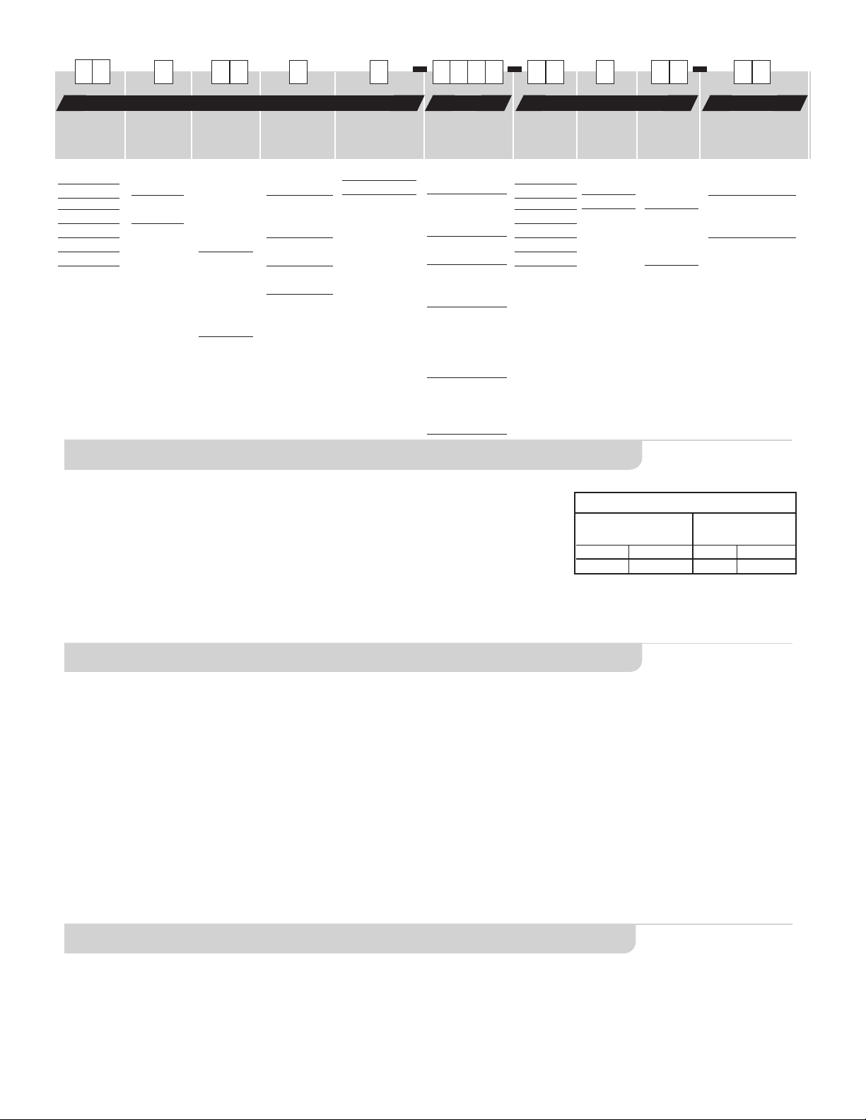
CONFIGURATIONS
Control
Valve
Size
P2
2.5” DN65
P3
3” DN80
P4
4” DN100
P5
5” DN125
P6
6” DN150
P8
8” DN200
P1
10” DN250
Control
Valve
Flange
0
ANSI 125
Flanges
2
PN16
Flanges
Control
Valve
Profile
22
Type of
Control
Valve
Body
(Sizes P8
& P1)
23
Type of
Control
Valve
Body
(Sizes
P2-P6)
Control
Valve Trim
Size
F
Control Valve
Trim Size Full
X
Control Valve
Trim Size
Extended
1
Control Valve
Trim Size 1SR
2
Control Valve
Trim Size 2SR
Control Valve
Trim Material
S
Stainless Steel
B
Bronze
Control Valve
Motor
E020
VM1500E Fail As Is
E021
VM1500E - w/
VMS-25
BCM
E022
VM5000E -
Fail As Is
E023
VM5000E - w/
VMS-25
BCM
TIG1
TR5000-X
-Fail As Is
for all exceot
P6_23XX
Extended Port
TIG2
TR5000-X
-Fail As Is
Extended Port
Only
DPRV
Size
P2
2.5” DN65
P3
3” DN80
P4
4” DN100
P5
P6
6” DN150
P8
8” DN200
P1
10” DN250
VALVE BODIES
Body Material: Cast Iron
End Connections: ANSI 125LB FF Flanges, PN16 FF Flanges
Trim Designs: Type 23 - Single Seat Cylinder Balanced, ANSI Class III Leakage
Type 22 and 72 - Double Seat Balanced, ANSI Class III Leakage
Trim Material: Bronze or 300 Series Stainless Steel
EPDM Seal (Type 23 w/Bronze Trim)
Fluoraz Seal (Type 23 w/Stainless Steel Trim)
Fluid: Chilled Water Typical, Water or Water/Glycol from 35 °F- 180°F (2°C - 82°C )
Trim Limits: Stainless Steel: MAX Flowing Differential Pressure, 150 PSIG (10.3 BARG)
Bronze: MAX Flowing Differential Pressure, 100 PSIG (6.9 BARG)
Packing: Long-Life Multi-Stack EPDM Lip Packing - Water / Water-Glycol Service
5” DN125
DPRV
Flange
DPRV
Trim
DPRV Actuator
Material
DS
DB
DPRV Type
72 Portion
w/ SS Trim
DPRV Type
72 Portion
w/ Brz
Trim
2L
DPRV Actuator Cast
Iron, w/ Low DP Spring
2M
DPRV Actuator Cast
Iron, w/ Medium DP
Spring
0
ANSI 125
Flanges
2
PN16 Flanges
Note: Must
match control
valve
Body Pressure Temperature Ratings
Iron Body
Temperature 125 FLG & PN16
O
F
35 to 180 1.7 to 82.2 150 10.20
O
C PSIG BARG
ELECTRIC ACTUATOR SPECIFICATIONS (VM-1500E AND VM-5000E)
Valve Usage: VM-1500E [Valve sizes 2 1/2, 3 & 4 Inch DN65, DN80 & DN100],
VM-5000E [Valve sizes 5, 6, 8 & 10 Inch DN125, DN150, DN200, DN250]
Control Signal: 4-20 mAdc (Factory Setting), 0-20 mAdc, 0-10 Vdc or 2-10 Vdc
and Floating, Self-Adjusting, Field Selectable (Dip Switch)
Power Consumption: VM-1500E 12VA, VM-5000E 25VA
Timing: VM-1500E [102 sec. / inch, 4.02 sec. / mm], VM-5000E [76 sec. / inch, 2.99 sec./mm]
Feedback Signal: 4-20 mAdc (Factory Setting), 0-10 Vdc or 2-10 Vdc
Failure Mode: Fail-As-Is [Without VMS-25 BCM (Back-up Control Module)]
Fail-Safe [With VMS-25 BCM (Back-up Control Module)]
Manual Override: Yes
Construction: Polycarbonate Motor Housing with Steel Linkage & Yoke.
Case has one 1/2 inch (1.27 cm) NPSM Conduit Adapter
Connections: Coded Screw Terminals
Locations: NEMA Type 3 / IP54
Temperature Limits: Ambient 32°F - 122°F ( 0°C - 50°C )
Mounting: Factory Aligned, Vertical Above Centerline of Control Valve
Consult factory for preconfigured alternate orientations
VMS-25 BCM (BACK-UP CONTROL MODULE) SPECIFICATIONS
Actuator Usage: VM-1500E & VM-5000E
Required for Fail Safe Operation
Failure Direction: Field Selectable
Power Consumption: 24VAC, 40VA
Construction: Battery w/Circuit Board & Transformer, in Nema 4 Enclosure
Mounting: Wall Mount
Weight: 4.25 lbs (2 kg)
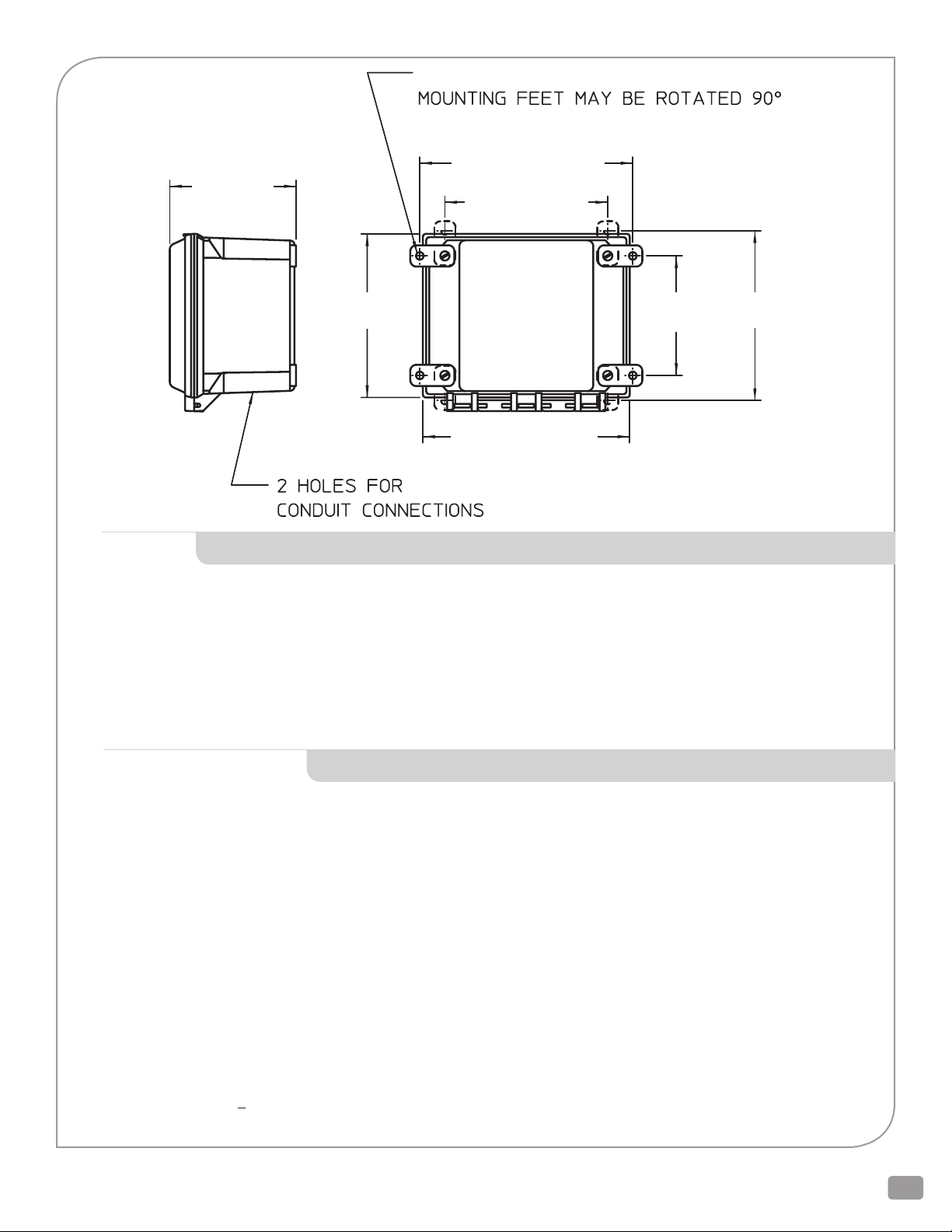
VMS-25 BCM
5.19 in
(13.18 cm)
4X 0.31 in (0.79 cm)
8.75 in (22.23 cm)
6.69 in (16.99 cm)
THRU MOUNTING FOOT
6.72 in
(17.O7 cm)
8.5 in (21.59 cm)
1/2 in (1.27 cm)
4.91 in
(12.47 cm)
6.97 in
(17.7O cm)
DPRV DOUBLE ACTING DIAPHRAGM ACTUATOR WITH SPRING ASSIST
Control Signal: Differential Pressure from Control Valve,
2.0 to 8 PISG (0.14 to 0.55 BARD)
150 PSIG (10.3 BARD) Max Static
Fluid: Chilled Water Typical, Water or Water/Glycol from 35 °F- 180°F (2°C - 82°C )
Spring Pack: Low DP Spring: Adjustable 2 to 6 PSIG (0.14-0.41 BARD)
Medium DP Spring: Adjustable 5 to 8 PSIG (0.34-0.55 BARD)
Construction: Cast Gray Iron Class G3000, epoxy coated, epoxy coated spring, SS components, Woven Buna-N, nylon reinforced.
Temperature Limits: Ambient 32°F - 122°F ( 0°C - 50°C )
Mounting: Factory Aligned, Vertical Above Centerline of Control Valve
Consult factory for preconfigured alternate orientations
ELECTRIC ACTUATOR SPECIFICATIONS (TR5000-X)
Valve Usage: 5, 6, 8, & 10 inch, DN125, DN150, DN200, DN250
Control Signal: 4-20 mAdc (Factory Setting), 0-10 Vdc, 2-10 Vdc, or 0-20 mAdc; Field Selectable (Dip Switch)
Control Action: Direct Acting, Actuator Shaft Extends on Increasing Signal (Factory Setting) or
Reverse Acting, Actuator Shaft Retracts on Increasing Signal; Field Selectable (Dip Switch)
Power Supply: 220 VAC
Power Consumption: 12VA
Timing: 90.68 Seconds / Inch (3.57 s/mm)
Feedback Signal: 4-20 mAdc (Factory Setting), 0-10 Vdc, 2-10 Vdc, or 0-20 mAdc
Field Selectable (Dip Switch); Feedback Signal Increase as Actuator Shaft Extends (Factory Setting) or Feedback
Signal Increases as Actuator Shaft Retracts; Field Selectable (Dip Switch)
Failure Mode: Fail Actuator Shaft Retracted on Loss of Signal (Factory Setting) or Fail Actuator Shaft Extended on Loss of Signal
Field Selectable (Dip Switch); Actuator Shaft Fails In Last Position on Loss of Power
Manual Override: Yes
Construction: Die Cast Aluminum Motor Housing & Yoke. Painted.
Case Has Two PG11 Cable Glands Accepts 0.197 to 0.394 inch (5mm to 10mm) Diameter Cable
Connections: Coded Screw Terminals
Locations: NEMA Type 3 / IP54
Temperature Limits: Ambient 14˚F to 122˚F ( -10˚C to 50˚C )
Relative Humidity: < 95% RH (40ºC)
Mounting: Factory Aligned, Vertical Above Centerline of Control Valve; Consult factory for preconfigured alternate orientations
PRESSURE INDEPENDENT CONTROL VALVE PICV_IOM_REVF_0114
3
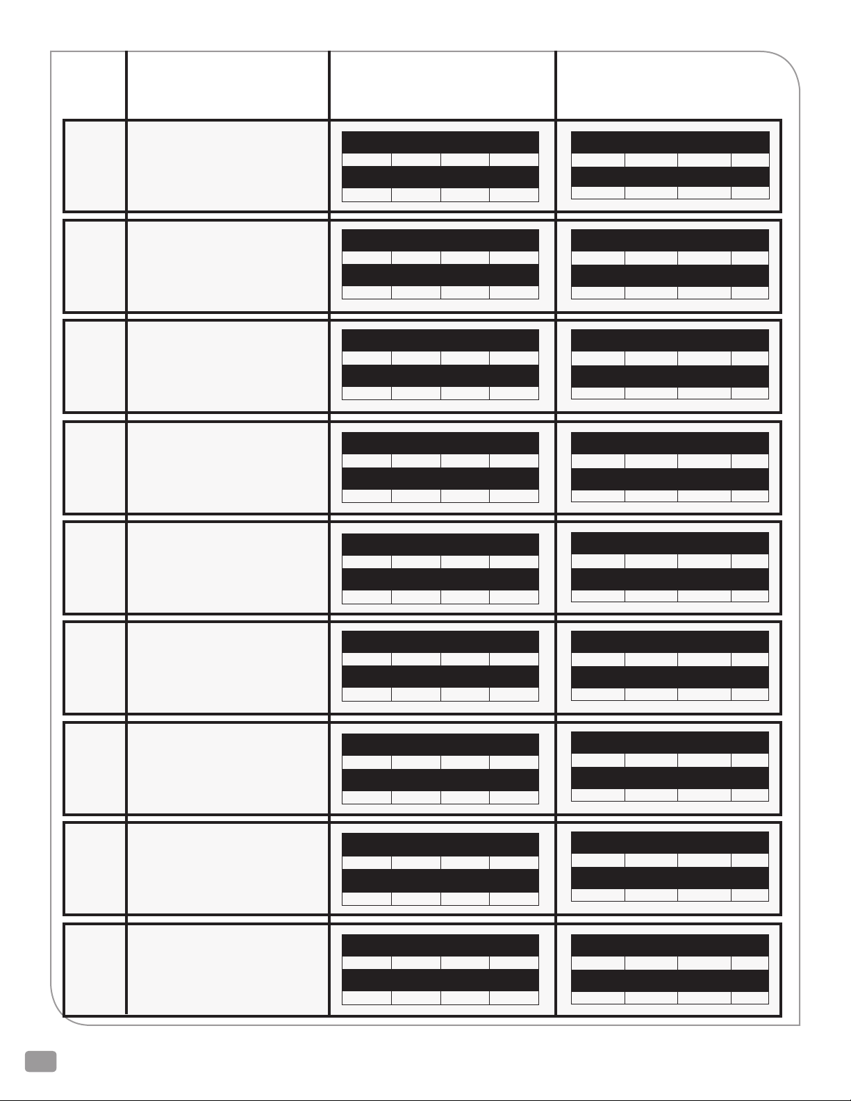
FLANGE
PRODUCT MODEL
(where ‘x’ is a configurable option)
LOW DP SPRING
PERFORMANCE
MEDIUM DP SPRING
PERFORMANCE
ANSI125
ANSI125
ANSI125
ANSI125
ANSI125
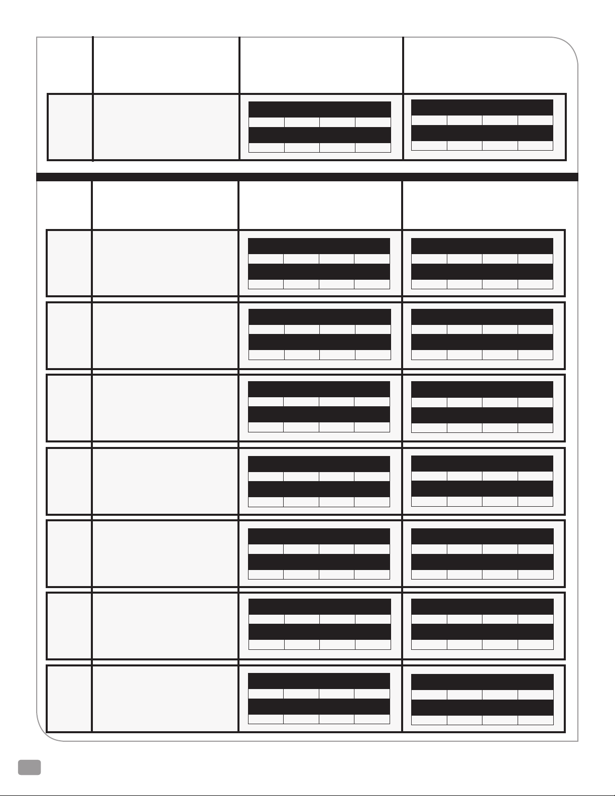
P2023Fx-xxxx-P20Dx-2x
2 1/2” Standard Port
P30231x-xxxx-P30Dx-2x
3” 1 Size Reduced Port
P3023Fx-xxxx-P30Dx-2x
3” Standard Port
P40232x-xxxx-P40Dx-2x
4” 2 Sizes Reduced Port
P40231x-xxxx-P40Dx-2x
4” 1 Size Reduced Port
Set Differential Pressure (PSI)
2.0 3.1 4.2 5.3
Maximum flow (GPM)
92 114 133 150
Set Differential Pressure (PSI)
2.0 3.1 4.2 5.3
Maximum flow (GPM)
106 132 154 173
Set Differential Pressure (PSI)
2.0 3.1 4.2 5.3
Maximum flow (GPM)
127 158 184 207
Set Differential Pressure (PSI)
2.0 3.1 4.2 5.3
Maximum flow (GPM)
165 206 240 269
Set Differential Pressure (PSI)
2.0 3.1 4.2 5.3
Maximum flow (GPM)
204 254 295 332
Set Differential Pressure (PSI)
5.7 6.5 7.2 8.0
Maximum flow (GPM)
155 166 174 184
Set Differential Pressure (PSI)
5.7 6.5 7.2 8.0
Maximum flow (GPM)
179 191 201 212
Set Differential Pressure (PSI)
5.7 6.5 7.2 8.0
Maximum flow (GPM)
215 229 241 255
Set Differential Pressure (PSI)
5.7 6.5 7.2 8.0
Maximum flow (GPM)
279 298 314 331
Set Differential Pressure (PSI)
5.7 6.5 7.2 8.0
Maximum flow (GPM)
344 367 386 407
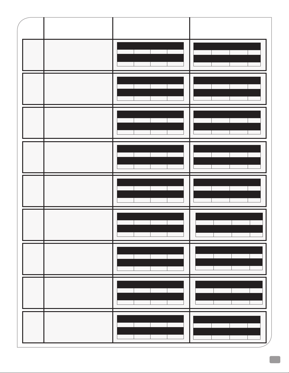
ANSI125
ANSI125
ANSI125
ANSI125
P4023Fx-xxxx-P40Dx-2x
4” Standard Port
P50232x-xxxx-P50Dx-2x
5” 2 Sizes Reduced Port
P50231x-xxxx-P50Dx-2x
5” 1 Size Reduced Port
P5023Fx-xxxx-P50Dx-2x
5” Standard Port
Set Differential Pressure (PSI)
2.0 3.1 4.2 5.3
Maximum flow (GPM)
240 299 348 391
Set Differential Pressure (PSI)
2.0 3.1 4.2 5.3
Maximum flow (GPM)
287 357 416 467
Set Differential Pressure (PSI)
2.0 3.1 4.2 5.3
Maximum flow (GPM)
335 417 486 546
Set Differential Pressure (PSI)
2.0 3.1 4.2 5.3
Maximum flow (GPM)
382 475 553 622
Set Differential Pressure (PSI)
5.7 6.5 7.2 8.0
Maximum flow (GPM)
406 433 456 481
Set Differential Pressure (PSI)
5.7 6.5 7.2 8.0
Maximum flow (GPM)
485 518 545 574
Set Differential Pressure (PSI)
5.7 6.5 7.2 8.0
Maximum flow (GPM)
566 604 636 670
Set Differential Pressure (PSI)
5.7 6.5 7.2 8.0
Maximum flow (GPM)
645 688 724 764
2600 Emrick Blvd • Bethlehem, PA 18020 • USA • 800-922-0085 • www.warrencontrols.com
4
FLANGE
PRODUCT MODEL
(where ‘x’ is a configurable option)
LOW DP SPRING
PERFORMANCE
MEDIUM DP SPRING
PERFORMANCE
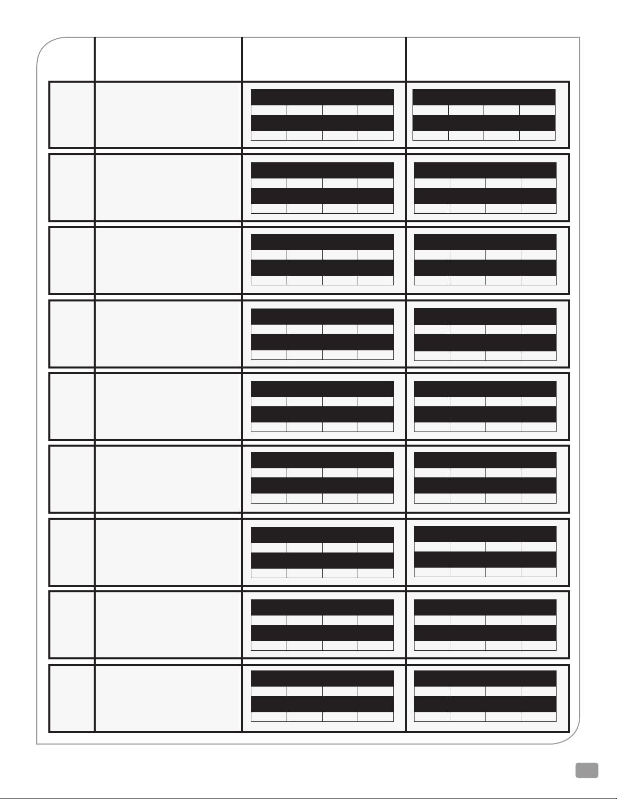
ANSI125
ANSI125
ANSI125
ANSI125
P60032x-xxxx-P60Dx-2x
6” 2 Sizes Reduced Port
P60231x-xxxx-P60Dx-2x
6” 1 Size Reduced Port
P6023Fx-xxxx-P60Dx-2x
6” Standard Port
P6023Xx-xxxx-P60Dx-2x
6” Extended Port
ANSI125
P80222S-xxxx-P80Dx-2x
8” 2 Sizes Reduced Port
SS Trim Only
Set Differential Pressure (PSI)
2.0 3.1 4.2 5.3
Maximum flow (GPM)
389 484 564 633
Set Differential Pressure (PSI)
2.0 3.1 4.2 5.3
Maximum flow (GPM)
445 555 646 725
Set Differential Pressure (PSI)
2.0 3.1 4.2 5.3
Maximum flow (GPM)
509 634 738 829
Set Differential Pressure (PSI)
2.0 3.1 4.2 5.3
Maximum flow (GPM)
594 739 861 967
Set Differential Pressure (PSI)
2.0 3.1 4.2 5.3
Maximum flow (GPM)
735 916 1066 1197
Set Differential Pressure (PSI)
5.7 6.5 7.2 8.0
Maximum flow (GPM)
657 701 738 778
Set Differential Pressure (PSI)
5.7 6.5 7.2 8.0
Maximum flow (GPM)
752 803 845 891
Set Differential Pressure (PSI)
5.7 6.5 7.2 8.0
Maximum flow (GPM)
859 918 966 1018
Set Differential Pressure (PSI)
5.7 6.5 7.2 8.0
Maximum flow (GPM)
1003 1071 1127 1188
Set Differential Pressure (PSI)
5.7 6.5 7.2 8.0
Maximum flow (GPM)
1241 1326 1395 1471
ANSI125
P80221S-xxxx-P80Dx-2x
8” 1 Size Reduced Port
SS Trim Only
ANSI125
ANSI125
P8023Fx-E02x-P80Dx-2x
8” Standard Port
P10222S-xxxx-P10Dx-2x
10” 2 Sizes Reduced Port
SS Trim Only
ANSI125
P10221S-xxxx-P10Dx-2x
10” 1 Size Reduced Port
SS Trim Only
Set Differential Pressure (PSI)
2.0 3.1 4.2 5.3
Maximum flow (GPM)
841 1048 1219 1370
Set Differential Pressure (PSI)
2.0 3.1 4.2 5.3
Maximum flow (GPM)
962 1197 1394 1565
Set Differential Pressure (PSI)
2.0 3.1 4.2 5.3
Maximum flow (GPM)
1039 1294 1506 1692
Set Differential Pressure (PSI)
2.0 3.1 4.2 5.3
Maximum flow (GPM)
1188 1479 1721 1934
Set Differential Pressure (PSI)
5.7 6.5 7.2 8.0
Maximum flow (GPM)
1421 1517 1597 1683
Set Differential Pressure (PSI)
5.7 6.5 7.2 8.0
Maximum flow (GPM)
1623 1734 1825 1923
Set Differential Pressure (PSI)
5.7 6.5 7.2 8.0
Maximum flow (GPM)
1755 1874 1972 2079
Set Differential Pressure (PSI)
5.7 6.5 7.2 8.0
Maximum flow (GPM)
2005 2142 2254 2376
PRESSURE INDEPENDENT CONTROL VALVE PICV_IOM_REVF_0114
5
FLANGE
PRODUCT MODEL
(where ‘x’ is a configurable option)
LOW DP SPRING
PERFORMANCE
MEDIUM DP SPRING
PERFORMANCE
ANSI125 P1022Fx-xxxx-P10Dx-2x
10” Standard Port
PRODUCT MODEL
FLANGE
PN16
PN16
PN16
(where ‘x’ is a configurable option)
P2223Fx-xxxx-P22Dx-2x
DN65 Standard Port
P32231x-xxxx-P32Dx-2x
DN80 1 Size Reduced Port
P3223Fx-xxxx-P32Dx-2x
DN80 Standard Port
Set Differential Pressure (PSI)
2.0 3.1 4.2 5.3
Maximum flow (GPM)
1358 1690 1967 2210
LOW DP SPRING
PERFORMANCE
Set Differential Pressure (BAR)
0.14 0.21 0.29 0.37
Maximum flow (LPS)
5.8 7.2 8.4 9.5
Set Differential Pressure (BAR)
0.14 0.21 0.29 0.37
Maximum flow (LPS)
6.7 8.3 9.7 11.0
Set Differential Pressure (BAR)
0.14 0.21 0.29 0.37
Maximum flow (LPS)
8.1 9.9 11.6 13.2
Set Differential Pressure (PSI)
5.7 6.5 7.2 8.0
Maximum flow (GPM)
2292 2448 2576 2715
MEDIUM DP SPRING
PERFORMANCE
Set Differential Pressure (BAR)
0.39 0.45 0.5 0.55
Maximum flow (LPS)
9.8 10.5 11.0 11.6
Set Differential Pressure (BAR)
0.39 0.45 0.5 0.55
Maximum flow (LPS)
11.3 12.1 12.7 13.4
Set Differential Pressure (BAR)
0.39 0.45 0.5 0.55
Maximum flow (LPS)
13.5 14.5 15.3 16.0
PN16
PN16
PN16
PN16
P42232x-xxxx-P42Dx-2x
DN100 2 Sizes Reduced Port
P42231x-xxxx-P42Dx-2x
DN100 1 Size Reduced Port
P4223Fx-xxxx-P42Dx-2x
DN100 Standard Port
P52232x-xxxx-P52Dx-2x
DN125 2 Sizes Reduced Port
Set Differential Pressure (BAR)
0.14 0.21 0.29 0.37
Maximum flow (LPS)
10.5 12.9 15.1 17.1
Set Differential Pressure (BAR)
0.14 0.21 0.29 0.37
Maximum flow (LPS)
12.9 15.9 18.6 21.0
Set Differential Pressure (BAR)
0.14 0.21 0.29 0.37
Maximum flow (LPS)
15.3 18.7 22.0 24.8
Set Differential Pressure (BAR)
0.14 0.21 0.29 0.37
Maximum flow (LPS)
18.2 22.4 26.3 29.7
Set Differential Pressure (BAR)
0.39 0.45 0.5 0.55
Maximum flow (LPS)
17.6 18.9 19.9 20.8
Set Differential Pressure (BAR)
0.39 0.45 0.5 0.55
Maximum flow (LPS)
21.6 23.2 24.5 25.7
Set Differential Pressure (BAR)
0.39 0.45 0.5 0.55
Maximum flow (LPS)
25.5 27.4 28.9 30.3
Set Differential Pressure (BAR)
0.39 0.45 0.5 0.55
Maximum flow (LPS)
30.5 32.7 34.5 36.2
2600 Emrick Blvd • Bethlehem, PA 18020 • USA • 800-922-0085 • www.warrencontrols.com
6
FLANGE
PRODUCT MODEL
(where ‘x’ is a configurable option)
LOW DP SPRING
PERFORMANCE
MEDIUM DP SPRING
PERFORMANCE
PN16
PN16
PN16
PN16
PN16
P52231x-xxxx-P52Dx-2x
DN125 1 Size Reduced Port
P5223Fx-xxxx-P52Dx-2x
DN125 Standard Port
P62232x-xxxx-P62Dx-2x
DN150 2 Sizes Reduced Port
P62231x-xxxx-P62Dx-2x
DN150 1 Size Reduced Port
P6223Fx-xxxx-P62Dx-2x
DN150 Standard Port
Set Differential Pressure (BAR)
0.14 0.21 0.29 0.37
Maximum flow (LPS)
21.3 26.1 30.7 34.6
Set Differential Pressure (BAR)
0.14 0.21 0.29 0.37
Maximum flow (LPS)
24.3 29.7 34.9 39.5
Set Differential Pressure (BAR)
0.14 0.21 0.29 0.37
Maximum flow (LPS)
24.7 30.3 35.6 40.2
Set Differential Pressure (BAR)
0.14 0.21 0.29 0.37
Maximum flow (LPS)
28.3 34.7 40.8 46.0
Set Differential Pressure (BAR)
0.14 0.21 0.29 0.37
Maximum flow (LPS)
32.4 39.6 46.6 53
Set Differential Pressure (BAR)
0.39 0.45 0.5 0.55
Maximum flow (LPS)
35.6 38.2 40.3 42.2
Set Differential Pressure (BAR)
0.39 0.45 0.5 0.55
Maximum flow (LPS)
40.5 43.5 45.9 48.1
Set Differential Pressure (BAR)
0.39 0.45 0.5 0.55
Maximum flow (LPS)
41.3 44.3 46.7 49.0
Set Differential Pressure (BAR)
0.39 0.45 0.5 0.55
Maximum flow (LPS)
47.3 51 54 56
Set Differential Pressure (BAR)
0.39 0.45 0.5 0.55
Maximum flow (LPS)
54 58 61 64
PN16
P6223Xx-xxxx-P62Dx-2x
PN16
DN150 Extended Port
P82222S-xxxx-P82Dx-2x
DN200 2 Sizes Reduced Port
SS Trim Only
PN16
P82221S-xxxx-P82Dx-2x
DN200 1 Size Reduced Port
SS Trim Only
PN16
P8223Fx-E02x-P82Dx-2x
DN200 Standard Port
Set Differential Pressure (BAR)
0.14 0.21 0.29 0.37
Maximum flow (LPS)
37.8 46.2 54 61
Set Differential Pressure (BAR)
0.14 0.21 0.29 0.37
Maximum flow (LPS)
46.7 57 67 76
Set Differential Pressure (BAR)
0.14 0.21 0.29 0.37
Maximum flow (LPS)
53 66 77 87
Set Differential Pressure (BAR)
0.14 0.21 0.29 0.37
Maximum flow (LPS)
61 75 88 99
Set Differential Pressure (BAR)
0.39 0.45 0.5 0.55
Maximum flow (LPS)
63 68 71 75
Set Differential Pressure (BAR)
0.39 0.45 0.5 0.55
Maximum flow (LPS)
78 84 88 93
Set Differential Pressure (BAR)
0.39 0.45 0.5 0.55
Maximum flow (LPS)
89 96 101 106
Set Differential Pressure (BAR)
0.39 0.45 0.5 0.55
Maximum flow (LPS)
102 110 116 121
PRESSURE INDEPENDENT CONTROL VALVE PICV_IOM_REVF_0114
7
FLANGE
PRODUCT MODEL
(where ‘x’ is a configurable option)
LOW DP SPRING
PERFORMANCE
MEDIUM DP SPRING
PERFORMANCE
PN16
P12222S-xxxx-P12Dx-2x
DN250 2 Sizes Reduced Port
SS Trim Only
PN16
P12221S-xxxx-P12Dx-2x
DN250 1 Size Reduced Port
SS Trim Only
PN16
P1222Fx-xxxx-P12Dx-2x
DN250 Standard Port
Set Differential Pressure (BAR)
0.14 0.21 0.29 0.37
Maximum flow (LPS)
66 81 95 107
Set Differential Pressure (BAR)
0.14 0.21 0.29 0.37
Maximum flow (LPS)
76 92 109 123
Set Differential Pressure (BAR)
0.14 0.21 0.29 0.37
Maximum flow (LPS)
86 106 124 140
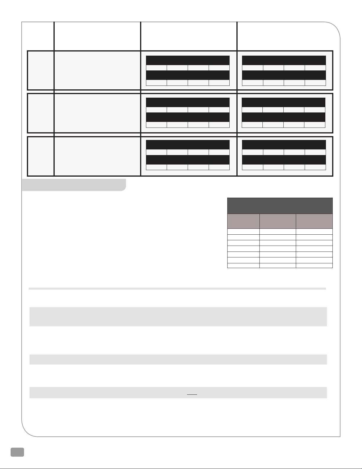
INSTALLATION
Recommended Piping: ANSI 125 Flanges should mate with piping with 125 Lb or 150 Lb
Flat Faced Flanges.
Per ISA Recommended Piping Practices. Control valves perform best with a reasonable
amount of upstream and downstream straight pipe prior to elbows and strainers. The
general specification for this is 16 pipe diameters upstream of straight pipe and 5 pipe
diameters downstream of straight pipe as minimums. However, this is a broad specification
covering all pipe diameters and velocities. Many applications do not have this kind of
space. While more length of straight pipe is desirable, Warren Controls has produced a
table of minimum pipe diameters for use on our PICV. Failure to follow these guidelines
may lead to noticeable vibrations or noise for excessive turbulence in some applications
with significant head pressure. In the unlikely event of excessive noise or vibration, other
remedies like special low noise trim may be available but at the expense of the user or
installer when not following installation guidelines.
Set Differential Pressure (BAR)
0.39 0.45 0.5 0.55
Maximum flow (LPS)
110 118 125 131
Set Differential Pressure (BAR)
0.39 0.45 0.5 0.55
Maximum flow (LPS)
126 135 143 150
Set Differential Pressure (BAR)
0.39 0.45 0.5 0.55
Maximum flow (LPS)
144 155 163 171
PICV Minimum Lengths of
Straight Pipe
PICV Size Upstream
Straight Pipe
2 ½” (DN65) 16” (40.64 cm) 12” (30.48 cm)
3” (DN80) 16” (40.64 cm) 12” (30.48 cm)
4” (DN100) 16” (40.64 cm) 12” (30.48 cm)
5” (DN125) 24” (60.96 cm) 12” (30.48 cm)
6” (DN150) 32” (81.28 cm) 12” (30.48 cm)
8” (DN200) 36” (91.44 cm) 14” (35.56 cm)
10” (DN250) 40” (101.6 cm) 16” (40.64 cm)
Downstream
Straight Pip
The above tables are recommended minimum lengths for good and stable performance. Wherever possible, longer runs of straight pipe
should be used for optimal performance and stability.
• Besurethattheflowmedium,ambienttemperatureandtheselectedlocationwillnotexceedthemaximumtemperatureofthePICV,
actuator, or accessories. Information can be found on the nameplate and product specifications regarding these limits.
• CheckPICVforanydamageduetoimproperstorageortransportation.Immediatelynotifyyoursalesorganizationofanydamaged
goods upon receipt. Do not attempt to move or disturb them further so photos may be taken. If the shipping container is noticeably
damaged, refuse receipt as the shipping company should be held liable, until a shipping representative is available to take photos.
• VerifythatthePICVisvisuallyingoodworkingorder–notbentorcracked.
• Followgoodpipingpractices.InstallabypassaroundthePICV.Installstopvalvesininletandoutletpipingtoprovidemeanstoisolate
PICV.
• THEPICVSHOULDBEINSTALLEDASAUNIT.THESEGMENTSSHOULDNOT BE SEPARATED FOR INSTALLATION.
• CarefullyremovethePICVfromshippingcratewithaportablehoistorcrane.ThePICVistooheavyforoneoreventwopeopletolift
and hand-install depending on size. The Crane or Hoist should use a strap or chain cradle around the central flanges of the two valve
assemblies to raise and maneuver the PICV into position at the pipe flanges. Efforts should be made to avoid damaging the sensing
lines and actuators during this installation procedure.
2600 Emrick Blvd • Bethlehem, PA 18020 • USA • 800-922-0085 • www.warrencontrols.com
8

• ProtectPICVanddownstreamequipmentwithanupstreamself-cleaningstrainer.
• FormaximumefficiencyandminimumwearinstallPICVIN VERTICAL POSITION with the stems POINTING UPWARD.
• Besuretoleave 6 INCHES (15.24 CM) OF CLEARANCE above the actuators to allow for actuator removal.
• Beforeinstalling,besurePICVandpipingareCLEAN INSIDE and FREE OF SCALE, chips, welding spatter, and foreign material.
Thoroughly blow out or flush pipe lines.
• ThePICVmustbeinstalledwiththefluidflowinthedirectionofthearrowontheflowarrowplate.
• PipesmustbealignedsquarelywiththePICVateachconnection.
• Tightenflangeboltsevenlytopreventexcessivestressandthepossibilityofcracking.Ifmatingflangesareraisedfacedtheymustbe
machined flat.
• ThePICVandaccessories(ifsoequipped)areassembled,tested,andcalibratedatthefactoryasaunit.Thenameplatespecifiesset-up
parameters used.
• Supplyairorpower,instrumentsignal,andaccessoriesshouldbeconnectedtoportsorterminalsasindicatedonthePICV.
• Verificationandtuningofthesetdifferentialpressuremayberequiredunderactualoperatingconditions.
PRESSURE INDEPENDENT CONTROL VALVE PICV_IOM_REVF_0114
9
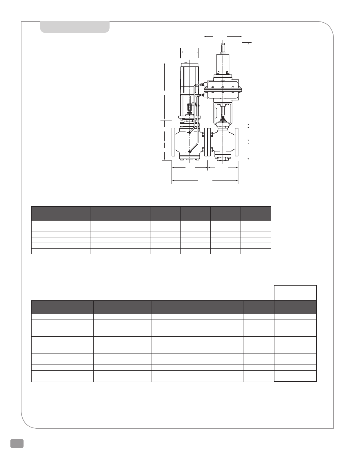
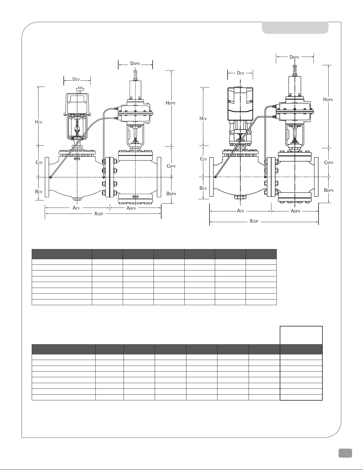
DIMENSIONS
ddpv
PICV SIZES:
2 1/2-4 IN (DN65-DN100)
Control Valve (Left)
Hcv
ccv
Bcv
dcv
WITH VM1500E ACTUATOR
Hdpv
cdpv
Bdpv
Acv Adpv
Xcdp
MODEL LISTING SIZE Acv Bcv Ccv Dcv Hcv
P2023xx-E02x-P20Dx-xx 2-1/2 9 in 4-3/4 in 5-3/4 in 4-7/8 in 14-3/4 in
P3023xx-E02x-P30Dx-xx 3 10 in 5-3/8 in 6-5/8 in 4-7/8 in 14-3/4 in
P4023xx-E02x-P40Dx-xx 4 13 in 6-3/8 in 7-3/4 in 4-7/8 in 14-3/4 in
P2223xx-E02x-P22Dx-xx DN65 22.86 cm 12.07 cm 14.61 cm 12.38 cm 37.47 cm
P3223xx-E02x-P32Dx-xx DN80 25.40 cm 13.65 cm 16.83 cm 12.38 cm 37.47 cm
P4223xx-E02x-P42Dx-xx DN100 33.02 cm 16.19 cm 19.69 cm 12.38 cm 37.47 cm
Acv +/- 1/16 in (0.16 cm) All other dimensions are maximum Allow 6 in (15.24 cm) above actuator for removal service
Total
Differential Pressure Valve (Right)
Model Listing SIZE Adpv Bdpv Cdpv Ddpv Hdpv Xcdp
P2023xx-E02x-P20Dx-2L 2-1/2 7-3/4 in 4-7/8 in 4-1/8 in 9-3/4 in 22-1/8 in 16-13/16 in
P2023xx-E02x-P20Dx-2M 2-1/2 7-3/4 in 4-7/8 in 4-1/8 in 9-3/4 in 26-3/4 in 16-13/16 in
P3023xx-E02x-P30Dx-2L 3 9 in 5-1/8 in 4-3/8 in 9-3/4 in 22-1/8 in 19-1/16 in
P3023xx-E02x-P30Dx-2M 3 9 in 5-1/8 in 4-3/8 in 9-3/4 in 26-3/4 in 19-1/16 in
P4023xx-E02x-P40Dx-2L 4 11-3/8 in 6-3/8 in 5-1/4 in 9-3/4 in 22-1/8 in 24-7/16 in
P4023xx-E02x-P40Dx-2M 4 11-3/8 in 6-3/8 in 5-1/4 in 9-3/4 in 26-3/4 in 24-7/16 in
P2223xx-E02x-P22Dx-2L DN65 19.69 cm 12.38 cm 10.48 cm 24.77 cm 56.20 cm 42.70 cm
P2223xx-E02x-P22Dx-2M DN65 19.69 cm 12.38 cm 10.48 cm 24.77 cm 67.95 cm 42.70 cm
P3223xx-E02x-P32Dx-2L DN80 22.86 cm 13.02 cm 11.11 cm 24.77 cm 56.20 cm 48.42 cm
P3223xx-E02x-P32Dx-2M DN80 22.86 cm 13.02 cm 11.11 cm 24.77 cm 67.95 cm 48.42 cm
P4223xx-E02x-P42Dx-2L DN100 28.89 cm 16.19 cm 13.34 cm 24.77 cm 56.20 cm 62.07 cm
P4223xx-E02x-P42Dx-2M DN100 28.89 cm 16.19 cm 13.34 cm 24.77 cm 67.95 cm 62.07 cm
combined*
* Includes gasket between Control Valve and Differential Pressure Valve
Adpv +/- 1/16 in (0.16 cm) Xcdp +/- 1/8 in (0.32 cm) All other dimensions are maximum
Allow 6 in (15.24 cm) above actuator for removal service
2600 Emrick Blvd • Bethlehem, PA 18020 • USA • 800-922-0085 • www.warrencontrols.com
10
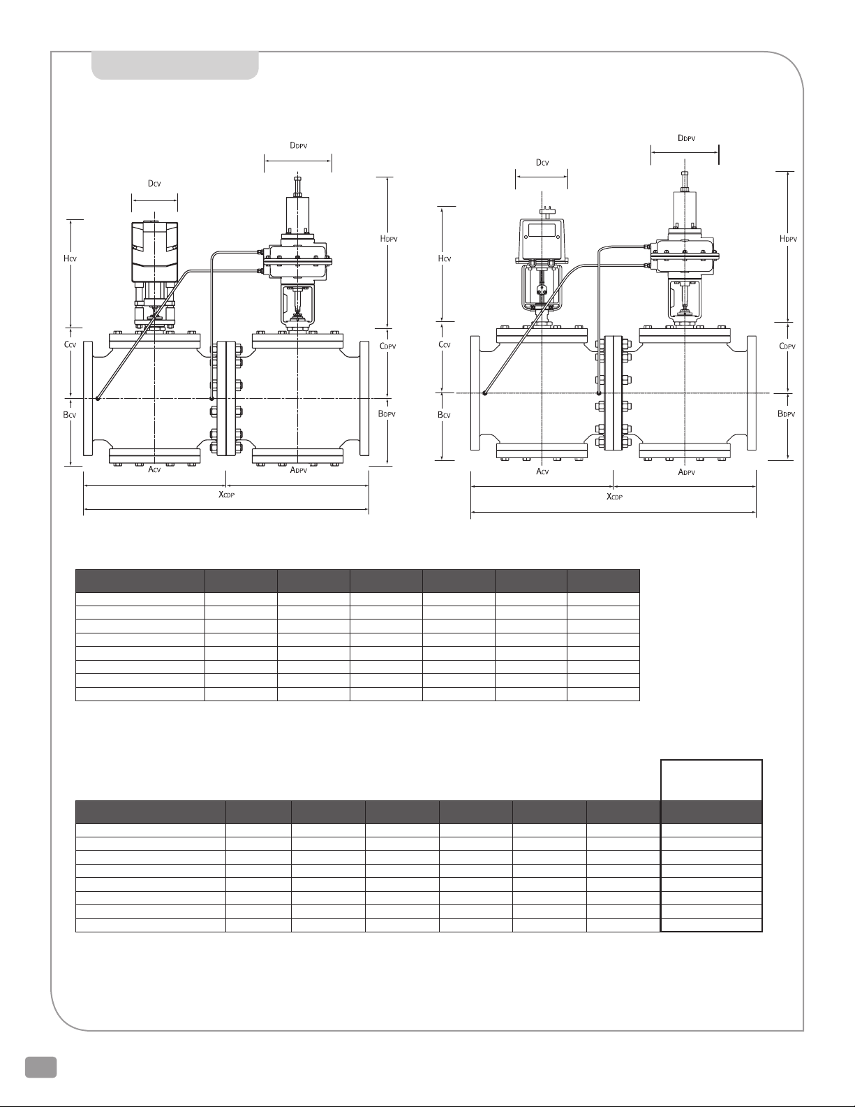
PICV SIZES: 5-6 IN (DN125-DN150)
WITH TR5000 ACTUATOR WITH VM5000E ACTUATOR
DIMENSIONS
Control Valve (Left)
MODEL LISTING SIZE Acv Bcv Ccv Dcv Hcv
P5023xx-E02x-P50Dx-xx 5 15-3/4 in 5-3/4 in 8-1/4 in 6-5/8 in 15-1/4 in
P5023xx-TIG1-P50Dx-xx 5 15-3/4 in 5-3/4 in 8-1/4 in 7-1/2 in 16-1/4 in
P6023xx-E02x-P60Dx-xx 6 17-3/4 in 6-1/2 in 8-7/8 in 6-5/8 in 15-1/4 in
P6023xx-TIGx-P60Dx-xx 6 17-3/4 in 6-1/2 in 8-7/8 in 7-1/2 in 16-1/4 in
P5223xx-E02x-P52Dx-xx DN125 40.01 cm 14.61 cm 20.96 cm 16.83 cm 38.74 cm
P5223xx-TIG1-P52Dx-xx DN125 40.01 cm 14.61 cm 20.96 cm 19.05 cm 41.28 cm
P6223xx-E02x-P62Dx-xx DN150 45.09 cm 16.51 cm 22.54 cm 16.83 cm 38.74 cm
P6223xx-TIGx-P62Dx-xx DN150 45.09 cm 16.51 cm 22.54 cm 19.05 cm 41.28 cm
Acv +/- 1/16 in (0.16 cm) All other dimensions are maximum Allow 6 in (15.24 cm) above actuator for removal service
Differential Pressure Valve (Right)
Model Listing SIZE Adpv Bdpv Cdpv Ddpv Hdpv Xcdp
P5023xx-xxxx-P50Dx-2L 5 12 in 6-7/8 in 7-5/8 in 9-3/4 in 22-1/8 in 27-13/16 in
P5023xx-xxxx-P50Dx-2M 5 12 in 6-7/8 in 7-5/8 in 9-3/4 in 26-3/4 in 27-13/16 in
P6023xx-xxxx-P60Dx-2L 6 14-1/8 in 7-5/8 in 8-1/2 in 9-3/4 in 22-1/8 in 31-15/16 in
P6023xx-xxxx-P60Dx-2M 6 14-1/8 in 7-5/8 in 8-1/2 in 9-3/4 in 26-3/4 in 31-15/16 in
P5223xx-xxxx-P52Dx-2L DN125 30.48 cm 17.46 cm 19.37 cm 24.77 cm 56.20 cm 70.64 cm
P5223xx-xxxx-P52Dx-2M DN125 30.48 cm 17.46 cm 19.37 cm 24.77 cm 67.95 cm 70.64 cm
P6223xx-xxxx-P62Dx-2L DN150 35.88 cm 19.37 cm 21.59 cm 24.77 cm 56.20 cm 81.12 cm
P6223xx-xxxx-P62Dx-2M DN150 35.88 cm 19.37 cm 21.59 cm 24.77 cm 67.95 cm 81.12 cm
* Includes gasket between Control Valve and Differential Pressure Valve
Adpv +/- 1/16 in (0.16 cm) Xcdp +/- 1/8 in (0.32 cm) All other dimensions are maximum
Allow 6 in (15.24 cm) above actuator for removal service
combined*
Total
PRESSURE INDEPENDENT CONTROL VALVE PICV_IOM_REVF_0114
11
DIMENSIONS
PICV SIZES: 8-10 IN DN200-DN250
WITH TR5000 ACTUATORWITH VM5000E ACTUATOR
Control Valve (Left)
MODEL LISTING SIZE Acv Bcv Ccv Dcv Hcv
P8022xx-E02x-P80Dx-xx 8 16-1/4 in 8-7/8 in 9-5/8 in 6-5/8 in 15 in
P8022xx-TIG1-P80Dx-xx 8 16-1/4 in 8-7/8 in 9-5/8 in 7-3/8 in 16-1/4 in
P1022xx-E02x-P10Dx-xx 10 20 in 9-5/8 in 10-1/8 in 6-5/8 in 15 in
P1022xx-TIG1-P10Dx-xx 10 20 in 9-5/8 in 10-1/8 in 7-3/8 in 16-1/4 in
P8222xx-E02x-P82Dx-xx DN200 41.28 cm 22.54 cm 24.45 cm 16.83 cm 38.10 cm
P8222xx-TIG1-P82Dx-xx DN200 41.28 cm 22.54 cm 24.45 cm 18.73 cm 41.28 cm
P1222xx-E02x-P12Dx-xx DN250 50.80 cm 24.45 cm 25.72 cm 16.83 cm 38.10 cm
P1222xx-TIG1-P12Dx-xx DN250 50.80 cm 24.45 cm 25.72 cm 18.73 cm 41.28 cm
Acv +/- 1/16 in (0.16 cm) All other dimensions are maximum Allow 6 in (15.24 cm) above actuator for removal service
Dierential Pressure Valve (Right)
Model Listing SIZE Adpv Bdpv Cdpv Ddpv Hdpv Xcdp
P8022xx-xxxx-P80Dx-2L 8 16-1/4 in 8-7/8 in 9-5/8 in 9-3/4 in 22-1/8 in 32-9/16 in
P8022xx-xxxx-P80Dx-2M 8 16-1/4 in 8-7/8 in 9-5/8 in 9-3/4 in 26-3/4 in 32-9/16 in
P1022xx-xxxx-P10Dx-2L 10 20 in 9-5/8 in 10-1/8 in 9-3/4 in 22-1/8 in 40-1/16 in
P1022xx-xxxx-P10Dx-2M 10 20 in 9-5/8 in 10-1/8 in 9-3/4 in 26-3/4 in 40-1/16 in
P8222xx-xxxx-P82Dx-2L DN200 41.28 cm 22.54 cm 24.45 cm 24.77 cm 56.20 cm 82.71 cm
P8222xx-xxxx-P82Dx-2M DN200 41.28 cm 22.54 cm 24.45 cm 24.77 cm 67.95 cm 82.71 cm
P1222xx-xxxx-P12Dx-2L DN250 50.80 cm 24.45 cm 25.72 cm 24.77 cm 56.20 cm 101.76 cm
P1222xx-xxxx-P12Dx-2M DN250 50.80 cm 24.45 cm 25.72 cm 24.77 cm 67.95 cm 101.76 cm
* Includes gasket between Control Valve and Differential Pressure Valve
Adpv +/- 1/16 in (0.16 cm) Xcdp +/- 1/8 in (0.32 cm) All other dimensions are maximum
Allow 6 in (15.24 cm) above actuator for removal service
combined*
Total
2600 Emrick Blvd • Bethlehem, PA 18020 • USA • 800-922-0085 • www.warrencontrols.com
12

PICV WEIGHTS
CONTROL VALVE
MODEL PICV SIZE
P2x23xx-E02x-P2xDx-2L 2-1/2 in, DN65 VM-1500E 2L 144.00 65.32
P2x23xx-E02x-P2xDx-2M 2-1/2 in, DN65 VM-1500E 2M 147.25 66.79
P3x23xx-E02x-P3xDx-2L 3 in, DN80 VM-1500E 2L 172.00 78.02
P3x23xx-E02x-P3xDx-2M 3 in, DN80 VM-1500E 2M 175.25 79.49
P4x23xx-E02x-P4xDx-2L 4 in, DN100 VM-1500E 2L 262.00 118.84
P4x23xx-E02x-P4xDx-2M 4 in, DN100 VM-1500E 2M 265.25 120.32
P5x23xx-E02x-P5xDx-2L 5 in, DN125 VM-5000E 2L 345.00 156.49
P5x23xx-E02x-P5xDx-2M 5 in, DN125 VM-5000E 2M 348.25 157.97
P5x23xx-TIG1-P5xDx-2L 5 in, DN125 TR5000-X 2L 335.40 152.14
P5x23xx-TIG1-P5xDx-2M 5 in, DN125 TR-5000-X 2M 338.65 153.61
P6x23xx-E02x-P6xDx-2L 6 in, DN150 VM-5000E 2L 438.00 198.68
P6x23xx-E02x-P6xDx-2M 6 in, DN150 VM-5000E 2M 441.25 200.15
P6x23xx-TIGx-P6xDx-2L 6 in, DN150 TR5000-X 2L 428.40 194.32
P6x23xx-TIGx-P6xDx-2M 6 in, DN150 TR-5000-X 2M 431.65 195.80
P8x22xx-E02x-P8xDx-2L 8 in, DN200 VM-5000E 2L 652.00 295.75
P8x22xx-E02x-P8xDx-2M 8 in, DN200 VM-5000E 2M 655.25 297.22
P8x22xx-TIG1-P8xDx-2L 8 in, DN200 TR5000-X 2L 642.40 291.39
P8x22xx-TIG1-P8xDx-2M 8 in, DN200 TR-5000-X 2M 645.65 292.86
P1x22xx-E02x-P1xDx-2L 10 in, DN250 VM-5000E 2L 945.00 428.65
P1x22xx-E02x-P1xDx-2M 10 in, DN250 VM-5000E 2M 948.25 430.12
P1x22xx-TIG1-P1xDx-2L 10 in, DN250 TR5000-X 2L 935.40 424.29
P1x22xx-TIG1-P1xDx-2M 10 in, DN250 TR-5000-X 2M 938.65 425.77
ACTUATOR
DPRV
ACTUATOR TOTAL WT (LBS) TOTAL WT (KG)
Weights for models with VM actuators do not include a VMS-25 BCM. Add 4.25 lbs (2kg) Actual shipping weights may vary.
MAINTENANCE
!
DANGER
Personal injury may result from uncontrolled
release of spring force. There is signicant
preload on the spring in the actuator on the
dierential pressure control segment (DPRV)
of the PICV. Disassembling the actuator will
release the spring force (preload) and may
cause serious personal injury.
maintenance free when properly selected and installed. Rebuilding of these valves
should not be necessary under normal operating conditions. For best operation
temperature, and flow within the limits of the valve (See Specification Section and
PICV Product Specification for details). In installations where high vibration exists,
Water should be in specification of the Warren Controls water quality guidelines.
Series PICV (Pressure Independent Control Valves) are for the most part
follow installation guidelines (See Installation); maintain the fluid pressures,
electrical and sensing connections should periodically be checked for integrity.
PACKING ADJUSTMENT
Series PICV packing is self-adjusting and requires no external adjustment.
UNDER NORMAL OPERATING CONDITIONS AND GOOD WATER QUALITY MANY YEARS OF MAINTENANCE FREE SERVICE CAN BE EXPECTED!
Control Valves in HVAC Water Systems
Fluid Quality and Service Life Guide Lines
The purpose of these guidelines is to avoid valve and water systems problems caused by poor water quality in HVAC systems. While all
cooling and heating systems are susceptible to problems, closed chilled water systems, including those containing brine or glycol, are
especially prone to system and valve problems. To achieve the satisfactory operation and maximum life of your Warren Controls valve, it is
important that the following recommendations are adhered to and that a water treatment, filtration and control specialists be consulted
before the system start-up.
PRESSURE INDEPENDENT CONTROL VALVE PICV_IOM_REVF_0114
13

VALVE PACKING LEAKS
The service life of valve stems and packing is dependent on
maintaining non-damaging fluid conditions. Inadequate treatment
or filtration, not in accordance with the recommendations of this
guide, or a qualified treatment specialist, can result in corrosion,
scaling, or abrasive particle formation. Scale and particles migrating
from pipe walls to control valves, will result in scratching the valve
stem, which will prevent the packing from sealing. This problem can
be avoided by the use of proper cleaning, treatment chemicals, and
storage procedures. Water must be treated and soft. Trace leaks of
hard water result in hard calcium carbonate particles on the outside
of the valve, which will scratch the sealing members creating a
packing leak. To avoid a damaging condition, the system should be
cleaned prior to start-up. Filtration equipment and strainers should
be employed as required and a regularly scheduled program of
water condition monitoring and treatment should be followed. Side
stream water filtration may be needed in closed systems, if there is
no regular blow down of the system.
STORAGE
Systems that are stored wet should be completely filled with
properly treated water and isolated to avoid slow leaks, which can
cause serious corrosion problems.
Control valve ‘hunting’ will cause excessive stroking of the valve
stem and result in premature failure of the valve packing seal. The
system must be stabilized to ensure reasonable packing life and
optimal control performance.
Over sizing of a control valve will result in an un-stable condition,
can result in, noise, vibration, premature trim and packing seal
failure. The use of the Warren Controls ValveWorks sizing program
Will facilitate the selection of the optimum valve.
COMMISSIONING
Thorough flushing of the system is necessary before start-up as new
systems, or old systems that have been shut down for an extended
period of time, will usually contain dirt, Weld slag, solder flux, and
pipe scale.
Drained system should be air dried, sealed, and treated with a
desiccant to prevent “atmospheric corrosion” of pipes, which is a
major source of pipe scale.
WATER QUALITY RECOMMENDED PARAMETERS
Chilled Water, Closed Loops, and Hot Water Systems up to 212°F (100° C).
8.0 < pH < 10.3
Conductivity < 3000 MMHS
!
C
CAUTION
The use of hydrazine can
result in the formation of
ammonia and must be controlled to prevent stress corrosion and embrittlement,
which can lead to fracture
of some brass alloys.
Water hardness should be less than 100 ppm of hard water ions (Ca++, Mg++), where 17.1 ppm = 1 Grain Hardness. Additionally, levels of
chloride and sulfate should remain less than 25 ppm. When water hardness is at unacceptable levels, a water softener expert should be
consulted.
hilled Systems
Hot Systems
Iron < 0.5 ppm
Copper < 0.5 ppm
100 ppm < Molybdenum < 150 ppm
(Mild Steel Corrosion Inhibitor)
200 ppm < Molybdenum < 250 ppm
(Mild Steel Corrosion Inhibitor)
400 ppm < Nitrite < 1000 ppm
(Mild Steel Corrosion Inhibitor)
Azole > 5 ppm free and available
(Yellow Metal Inhibitor)
Bacteria < 1000 cells/ml
(when system is cool)
ANTIFREEZE SOLUTIONS-GLYCOLS
The commonly used heat transfer glycol fluids are, either ethylene glycol or propylene glycol. Glycol concentrations of <25% often do not
provide sufficient corrosion inhibiting properties and at levels <20% can actually provide a food source for bacteria. As bacteria consume
the food and die off, a highly acidic condition can result. The recommended concentration for popular glycol based solutions is 25% to 60%.
2600 Emrick Blvd • Bethlehem, PA 18020 • USA • 800-922-0085 • www.warrencontrols.com
14

VM5000E &
VM1500E
ACTUATOR
INSTRUCTIONS
Page
Actuator Set-up & Wiring .....................16-18
VMS-25 Installation & Wiring ....................18
VM1500E 4-20mA Feedback Kit .................19
VM5000E 4-20mA Feedback Kit ................20
VM1500E Removal & Installation .............. 21
VM5000E Removal & Installation ..............21
PRESSURE INDEPENDENT CONTROL VALVE PICV_IOM_REVF_0114
15

SET-UP
SP ........................ 24 volts AC power in
SN ....................... Common (Ground) and control signal negative
(See wiring diagrams)
Y .......................... Control signal in (Positive)
X .......................... Feedback signal out (Positive)
1 .......................... Override
3 .......................... Override
SWITCH FUNCTIONS
Switch OFF ON
1 Voltage Control Signal Milliamp Control Signal
2 2 - 10 Volts or 4 - 20 ma 0 - 10 volts or 0 - 20 ma
3 Direct Acting Reverse Acting
(Extend on increasing signal) (Retract on increasing signal)
4 Full Range Split Range
5 Low Range Signal High Range Signal
6 Proportional 3 Point Floating
7 Equal Percentage Valve (Default) Linear Valve
8 (Default) DO NOT USE
9 Reset Reset
Feedback Positive
0 - 10 or 2 - 10 Vdc
Control signal
Positive
24 volts ac
Common and control signal negative
If system is grounded, then ground SN
24 volts ac
Terminal 1 St em down
Terminal 3 St em up
Override
Common and
control signal negative
24 volts ac
In the over ride pos ition the Ac tuator i s driven
to the end p osition . Connect ing to term inal
1 drives t he stem dow n. Connec ting to
termin al 3 drives t he stem up.
When the actuator settings are known, it is easier to make them
before the valve and actuator are installed in the system. When
power is first applied to the actuator, check to see that it moves
through its full range. If it does not, reset it by moving switch #9.
MANUAL OPERATION AND OVERRIDE
The actuator can be manually operated with a metric hex wrench. The
VM1500E uses a 4mm hex wrench. The VM5000E uses an 8mm hex
wrench. The socket is on top of the actuator. VM5000E actuators have
a clutch button that must be depressed while manually operating the
actuator. De-Energize the actuator before manual operation.
OVERRIDE
:
Connecting the neutral (terminal SN) to terminal 1 lowers the stem
and to terminal 3 raises the stem. This can be done by an external
switch or controller.
AUTOMATIC STROKE ADJUSTMENT
The stroke adjusts itself automatically. This happens the first time
power is applied or whenever the position of switch #9 is changed.
Adjustment takes several minutes during which the actuator will
move through its full stroke 2 or 3 times. The actuator remembers the
settings so a power failure does not cause the actuator to reset itself.
The automatic stroke adjustment does not work if the valve stroke
is greater than the limits of the actuator. The maximum strokes are:
VM1500E 1 1/2” 40 MM
VM5000E 2 1/8” 55 MM
Automatic stroke adjustment ensures that the signal range covers
the actual stroke of the valve.
RESET
Changing the position of switch #9 makes the actuator recalculate
the stroke. Do this if the actuator has been used on another valve,
tested without being on the valve, has been incorrectly mounted on
the valve, or has been taken off of the valve and reinstalled.
CONTROL SIGNALS
The actuator must be set for the control signal being used and
whether the signal is direct acting or reverse acting.
The acceptable signals are:
FLOATING
or any of the following proportional signals.
24 VOLTS AC 3 POINT
2600 Emrick Blvd • Bethlehem, PA 18020 • USA • 800-922-0085 • www.warrencontrols.com
16

Full Range Split Range
Actuator
Stroke
Stroke
Flow
Valve
Flow
Signal
Actuator
Signal
Stroke
Stroke
Flow
Valve
Flow
Valve + Actuator
Signal
Flow
Valve
Stroke
Flow
Valve + Actuator
Signal
Stroke
Flow
Valve
Flow
Valve + Actuator
Signal
Stroke
Flow
Valve
Flow
Valve + Actuator
Signal
Flow
Valve
Flow
Valve + Actuator
Signal
Flow
Valve + Actuator
Signal
Flow
0 - 10 vdc 0 - 5 vdc 5 - 10 vdc
2 - 10 vdc 2 - 6 vdc 6 - 10 vdc
0 - 20 ma 0 - 10 ma 10 - 20 ma
4 - 20 ma 4 - 12 ma 12 - 20 ma
Split ranges allow two actuators to be operated in sequence from
one full range signal. Proportional signals are programmed with
switches 1 - 5. The actuators are set for floating control by turning
on switch #6. Turning switch #6 on deactivates switches 1 - 5.
Please note the wiring for floating control differs from the wiring for
proportional control.
SELECTING THE SIGNAL
Floating Switch #6 ON
Proportional Switch #6 OFF
SIGNAL SWITCH NUMBER
VOLTS 1 2 4 5
2 - 10 OFF OFF OFF OFF
0 - 10 OFF ON OFF OFF
2 - 6 OFF OFF ON OFF
6 - 10 OFF OFF ON ON
0 - 5 OFF ON ON OFF
5 - 10 OFF ON ON ON
When switch #6 is on
switches 1-5 are inactive.
DIRECT OR REVERSE ACTING
An increasing signal can either drive the valve stem down
(direct acting) or up (reverse acting).
Reverse Acting Switch #3 ON
Properly selected and sized control valves utilize the default
(OFF) positions for switches #7 & #8.
Contact Warren Controls (Ph: 800-922-0085) before repositioning
either switch.
FLOW CHARACTERISTIC:
Change Flow Characteristic Switch #7
IN THE OFF POSITION STEM TRAVEL IS PROPORTIONAL TO CONTROL SIGNAL AND DOES NOT ALTER THE FLOW CHARACTERISTIC OF
VALVE. THIS IS THE POSITION SWITCH #7 SHOULD BE IN NORMALLY.
When the stem travel of an actuator is proportional to the control
signal, the shape (flow characteristic) of the valve’s plug determines
the flow. PICV valves have an equal percentage flow characteristic.
An equal percentage valve opens slowly at the start so that 25%
stem travel results in less than 25% flow. When Switch #7 is in the
ON position the stroke is electronically adjusted so that an equal
percentage valve performs as if it had a linear flow characteristic. A
linear valve opens so that 25% stem travel results in 25% flow.
MILLIAMPS 1 2 4 5
4 - 20 ON OFF OFF OFF
0 - 20 ON ON OFF OFF
4 - 12 ON OFF ON OFF
12 - 20 ON OFF ON ON
0 - 10 ON ON ON OFF
10 - 20 ON ON ON ON
EQUAL PERCENTAGE VALVE & SWITCH #7 OFF
SWITCH 8: FACTORY DEFAULT OFF
The correct position for Switch #8 is OFF.
Do not use the Switch #8 ON. If Switch #8 is ON the valve will not function properly as a PICV.
NOTE: Previous models were equipped with three movable jumpers in place of the 9-switch block for actuator setup. For information about them contact
Warren Controls (Ph: 800-922-0085).
SIGNAL SWITCH NUMBER
Signal
Stroke
Flow
Signal
Valve + Actuator
EQUAL PERCENTAGE VALVE & SWITCH #7 ON
Signal
Actuator
Stroke
Signal
Valve + Actuator
PRESSURE INDEPENDENT CONTROL VALVE PICV_IOM_REVF_0114
17

PRODUCT: SERIES VM LINEAR ELECTRIC ACTUATORS
NATURE OF FAULT: Actuator motor does not de-energize at one end of travel. Actuator does not
respond to Input signal changes.
PROBABLE CAUSE: Over-travel device cannot reach limit switch activation point.
CORRECTIVE ACTION(S):
1. De-energize the actuator, both power and signal.
2. Remove the actuator cover and locate the two switches soldered onto the circuit board. Note
the small lever protruding through the board, between the switches.
3. Using a hex wrench, declutching if necessary, manually drive the actuator away from its’ end of
travel. Note that the lever moves to a “rest” position.
4. Loosen the circuit board mounting screws sufficiently to allow the board to be moved in its’
slotted mounting holes.
5. Position the board so the lever is centered between the switches and re-tighten the mounting
screws. Check position again, after tightening.
6. Re-energize the actuator, and perform “Auto-Stroke”. Observe that the actuator travels fully in
both directions, and comes to rest at the point dictated by the applied input signal.
For oating control, connect controller with dry contacts and
TERMINALS
L System Power 24VAC
LN System Neutral
BT Battery Test
RC Remote Control
TG Te st G rou nd
C1 Relay Common 1st Motor
C2 Relay Common 2nd Motor
NC1 Relay Normally Closed 1st Motor
NC2 Relay Normally Closed 2nd Motor
NO1 Relay Normally Open 1st Motor
NO2 Relay Normally Open 2nd Motor
AC 24 Volt Out
oating mid position between terminal NO1 and 1 and 3 for
Actuator A, and between terminal NO2 and 1 and 3 for Actuator B.
LEVER, CORRECTLY
POSITIONED
BETWEEN
SWITCHES
VMS-25
Operation:
Proportional Normal: Terminal AC is connected to 24
VAC building power. Terminal LN supplies power to
SN. Actuator responds to modulating input signal.
Power Failure: Terminal AC changes to 24V square
wave from inverter. Terminal C2 connects to Terminal
NC2. Terminal NC2 supplies power to Termial 1 or 3 to
drive actuator to fail safe position.
INSTALLATION
1. Connect the VMS-25 to the actuators as shown. Connect NC1 or
NC2 to terminal 1 on an actuator to drive the valve stem down during
power failure or to terminal 3 to drive the valve stem up during a
power failure.
2. Connect VMS-25 to 24 volts AC power.
3. Connect the red wire to the battery positive (+) and the black wire
to the battery negative (-).
Note: Connect the 24 volt power to the VMS-25 before connecting
the battery. Connecting the battery first causes the VMS-25 to
go into the power failure mode. If there are conditions other than
power failure during which the actuator should be driven to the end
position, replace the jumper between LN & RC with a contact that
opens on demand.
2600 Emrick Blvd • Bethlehem, PA 18020 • USA • 800-922-0085 • www.warrencontrols.com
18
TESTING
Disconnecting the jumper between LN & RC, with building
power on, will drive the actuator to the power failure position.
Testing the VMS-25 and the battery. Measure the voltage
between TG & BT. TG is negative. When the power supply is charging
correctly the voltage will be 13 - 14 volts DC. Disconnect LN or L and
then measure the voltage between TG & BT. If the battery is good
and adequately charged the voltage will be Between 10 - 12 volts
DC. VMS-25 is a standby power supply for VM1500E and VM5000E
actuators. It is intended to drive these actuators to either open or
close a valve during a power failure. The VMS-25 can power one
VM5000E or two VM1500E actuators.

VM1500E MOTOR ACTUATOR
Installation of modication circuit board • PUR 1137
IN KIT NUMBER KVM1500EFB4TO20MA00
to convert native 2-10 vdc feedback output to optional 4-20 mAdc.
OVERVIEW:
VM motor actuators feature a native DC voltage position feedback output available
at motor terminals X (+) and SN (-). Addition of the optional circuit board shown
above converts the feedback output to 4-20 mAdc, available at terminals 4-20mA
(+) and N (-), capable of working into load resistances as high as 550 ohms. The
circuit operates on 24 vac fed from terminal SP (hot) to terminal SP on the mod.
board, and terminal SN (common) to terminal SN on the mod. board. A single wire
brings feedback from motor terminal X to mod. board terminal 2-10V. An adjustment potentiometer on the mod. board can calibrate the 4-20 mAdc feedback output at any critical point in the actuator’s travel. Nominal adjustment span, when
voltage feedback is 2 vdc, is from 3.5 to 4.5 mAdc output.
MATERIALS & TOOLS:
Wires and mounting screws are provided in the kit. The illustration that follows
shows RED wire insulation for power (hot), BLACK for power (neutral) and GREEN
for feedback. Stranded wire is used to avoid difficulty in connecting two wires to a
single terminal on the motor board. A small straight-bladed screwdriver is needed
for the wiring terminals, and a #2 Phillips screwdriver for the mounting screws
PUR 1137
4-20 mAdc Mod. Board
VM1500E KVM1500EFB4TO20MA00
A. Using two mounting screws, fasten the mod. board to the two existing bosses on the motor housing. Note the rectangular wire-
clearance cutout at the upper left.
B. Install the RED wire from motor board terminal SP to mod. board terminal SP.
C. Install the BLACK wire from motor board terminal SN to mod. board terminal SN.
D. Install the GREEN wire from motor board terminal X to mod. board terminal 2-10V.
E. Installation is complete. Connect the motor actuator in accordance with the Installation, Operating & Maintenance manual, except that
feedback output is now located at mod. board terminals 4-20mA (+) and N (-).
PRESSURE INDEPENDENT CONTROL VALVE PICV_IOM_REVF_0114
19

VM5000E MOTOR ACTUATOR
Installation of modication circuit board • PUR 1137
IN KIT NUMBER KVM5000EFB4TO20MA00
to convert native 2-10 vdc feedback output to optional 4-20 mAdc.
OVERVIEW:
VM motor actuators feature a native DC voltage position feedback output
available at motor terminals X (+) and SN (-). Addition of the optional circuit
board shown above converts the feedback output to 4-20 mAdc, available at
terminals 4-20mA (+) and N (-), capable of working into load resistances as
high as 550 ohms. The circuit operates on 24 vac fed from terminal SP (hot)
to terminal SP on the mod. board, and terminal SN (common) to terminal
SN on the mod. board. A single wire brings feedback from motor terminal
X to mod. board terminal 2-10V. An adjustment potentiometer on the mod.
board can calibrate the 4-20 mAdc feedback output at any critical point in
the actuator’s travel. Nominal adjustment span, when voltage feedback is 2
vdc, is from 3.5 to 4.5 mAdc output.
MATERIALS & TOOLS:
Wires and mounting screws are provided in the kit. The illustrations that follow show RED wire insulation for power (hot), BLACK for power (neutral) and
GREEN for feedback. Stranded wire is used to avoid difficulty in connecting
two wires to a single terminal on the motor board. A small straight-bladed
screwdriver is needed for the wiring terminals, and a #2 Phillips screwdriver
for the mounting screws
PUR 1137
4-20 mAdc Mod. Board
VM5000E KVM5000EFB4TO20MA00
A. Using four mounting screws, fasten the mod. board to the existing bosses on top of the motor housing. Note the semicircular
clutch clearance cutout on the right side.
B. Install the RED wire from motor board terminal SP to mod. board terminal SP.
C. Install the BLACK wire from motor board terminal SN to mod. board terminal SN.
D. Install the GREEN wire from motor board terminal X to mod. board terminal 2-10V.
E. Installation is complete. Connect the motor actuator in accordance with the Installation, Operating & Maintenance manual,
except that feedback output is now located at mod. board terminals 4-20mA (+) and N (-).
2600 Emrick Blvd • Bethlehem, PA 18020 • USA • 800-922-0085 • www.warrencontrols.com
20

Read all instructions carefully before beginning.
TURNING THE ACTUATOR LEGS CAUSES DAMAGE TO THE ACTUATOR AND VOIDS THE WARRANTY.
REMOVAL OF VM1500E ACTUATOR FROM VALVE
1) Remove line pressure and isolate valve in piping.
2) Operate actuator so plug is o seat(s) and tabs of anti-rotation device
(Item 2) can be unbent in Step 5.
3) Loosen jamnut (Item 3) and thread to bottom of threads on valve
stem.
4) Loosen yoke locknut until it is free of bonnet.
5) Unbend tabs of anti-rotation device.
6) Remove anti-rotation device from stem connector so stem connector
may be turned.
7) Hold jamnut on valve stem and tur n the stem connector to disengage
from valve stem. The valve stem should never be turned while the
plug is in contact with the seat otherwise the seating surfaces
will be damaged.
8) Remove actuator from valve.
_______________________________________________
INSTALLATION OF VM1500E ACTUATOR ON VALVE.
THE BRASS SPACER THAT COMES WITH THE ACTUATOR MUST BE ASSEMBLED
ON BOTTOM SIDE OF YOKE AS SHOWN ON DRAWING C3400002.
1) Push valve stem down until plug is seated. Note stem location.
2) Install hex jamnut (Item 3) on valve stem. Thread jamnut to bottom of
threads on stem.
3) Place actuator, yoke locknut, and anti-rotation device (Item 2) over
valve stem and onto bonnet. Watch orientation of yoke locknut and
anti-rotation device. Anti-rotation device must be oriented so tabs
can be bent around cross bar in Step 6. Actuator must rest on bonnet.
If necessary use actuator manual override to reposition the stem
connector. The manual override is at the top of the actuator. Turn
override using a 4mm hex wrench. Do not tighten yoke locknut at
this time.
4) Rotate actuator to desired orientation. For the factory default
actuator position face the actuator circuit board and install the
actuator on the valve with the valve upright and its inlet to the left.
Thread yoke locknut onto bonnet and tighten securely. Use a blunt
chisel and hammer for nal tightening.
5) Lift valve stem. Hold jamnut on valve stem and turn the stem
connector to engage valve stem. If necessary use actuator manual
override to reposition the stem connector. The valve stem should
never be turned while the plug is in contact with the seat
otherwise the seating surfaces will be damaged. The minimum
required stem engagement is 3/8 inch (9.53 mm). After required stem
engagement is reached thread jamnut up valve stem to contact stem
connector. Tighten jamnut to secure valve stem to stem connector.
6) Install anti-rotation device on cross bar and bend tabs over so stem
connector will not turn.
7) Push red travel indicators on leg of actuator into contact with cross
bar. Connect power to actuator. On circuit board turn dipswitch 9
ON then OFF. Actuator will perform automatic stroke adjustment. In
the stem down direction the plug must reach the seat in the valve
before the brass bar on the shaft inside the motor housing contacts
the bottom of the motor housing. The lever extending through the
hole in the circuit board deects to depress the upper microswitch on
the circuit board to stop the motor at that end of travel. In the stem up
direction the plug must reach the upper seat or travel stop inside the
valve before the stem connector contacts the bottom of the motor
housing. The lever extending through the hole in the circuit board
deects to depress the lower microswitch to stop the motor at that
end of travel. If necessary turn o power, loosen jamnut, remove antirotation device from stem connector, and repeat Steps 5 thru 7.
8) Turn o power. Make necessary dipswitch settings and additional
wiring connections. See Set-Up and Wiring sections of these
instructions.
9) Return power to actuator.
10) Return line pressure to valve.
11) Stroke valve several times to check operation.
Read all instructions carefully before beginning.
TURNING THE ACTUATOR LEGS CAUSES DAMAGE TO THE
ACTUATOR AND VOIDS THE WARRANTY.
REMOVAL OF VM5000E ACTUATOR FROM VALVE
1) Remove line pressure and isolate valve in piping.
2) Operate actuator so plug is o seat(s) and anti-rotation device (Item 2)
can be removed in Step 4.
3)
Loosen jamnut (Item 3) and thread to bottom of threads on valve stem.
4) Remove anti-rotation device from stem connector so stem connector
may be turned.
5) Loosen yoke locknut until it is free of bonnet.
6) Hold jamnut on valve stem and tur n the stem connector to disengage
from valve stem. The valve stem should never be turned while the
plug is in contact with the seat otherwise the seating surfaces
will be damaged.
7) Remove actuator from valve.
_______________________________________________
INSTALLATION OF VM5000E ACTUATOR ON VALVE.
THE BRASS SPACER THAT COMES WITH THE ACTUATOR MUST BE ASSEMBLED
ON BOTTOM SIDE OF YOKE AS SHOWN ON DRAWING C3400001.
1) Push valve stem down until plug is seated. Note stem location.
2) Install hex jamnut (Item 3) on valve stem. Thread jamnut to bottom of
threads on stem.
3)
Place actuator, yoke locknut, and anti-rotation device (Item 2) over
valve stem and onto bonnet. Watch orientation of yoke locknut and
anti-rotation device. Actuator must rest on bonnet. If necessary use
actuator manual override to reposition the stem connector. The
manual override is at the top of the actuator. There are t wo rubber caps
on the actuator cover. One cap covers the override; the second cap
covers the clutch. Remove both caps. Depress clutch and turn override
using an 8mm hex wrench. Replace caps when nished to protect
motor and circuit board. Do not tighten yoke locknut at this time.
4) Rotate actuator to desired orientation. For the factory default
actuator position face the actuator circuit board and install the
actuator on the valve with the valve upright and its inlet to the left.
Thread yoke locknut onto bonnet and tighten securely. Use a blunt
chisel and hammer for nal tightening.
5) Lift valve stem. Hold jamnut on valve stem and turn the stem
connector to engage valve stem. If necessary use actuator manual
override to reposition the stem connector. The valve stem should
never be turned while the plug is in contact with the seat
otherwise the seating surfaces will be damaged. The minimum
required stem engagement is 9/16 inch (14.29 mm). After required
stem engagement is reached thread jamnut up valve stem to contact
stem connector. Tighten jamnut to secure valve stem to stem
connector.
6) I
nstall anti-rotation device on cross bar so stem connec tor will not turn.
7) Push red travel indicators on legs of actuator into contact with cross
bar. Connect power to actuator. On circuit board turn dipswitch 9 ON
then OFF. Actuator will perform automatic stroke adjustment. In the
stem down direction the plug must reach the seat in the valve before
the cross bar on the actuator legs pushes the red travel indicators
on legs of actuator against the actuator base. The lever extending
through the hole in the circuit board deects to depress the upper
microswitch on the circuit board to stop the motor at that end of
travel. In the stem up direction the plug must reach the upper seat
or travel stop inside the valve before the cross bar pushes the red
travel indicators against the bottom of the motor housing. The valve
stem must not contact the bottom of the motor housing. The lever
extending through the hole in the circuit board deects to depress
the lower microswitch to stop the motor at that end of travel. If
necessary turn o power, loosen jamnut, remove anti-rotation device
from stem connector, and repeat Steps 5 thru 7.
8) Turn o power. Make necessary dipswitch settings and additional
wiring connections. See Set-Up and Wiring sections of these
instructions.
9) Return power to actuator.
10) Return line pressure to valve.
11) Stroke valve several times to check operation.
PRESSURE INDEPENDENT CONTROL VALVE PICV_IOM_REVF_0114
21

C3400001
C3400002
2600 Emrick Blvd • Bethlehem, PA 18020 • USA • 800-922-0085 • www.warrencontrols.com
22

TR5000-X
ACTUATOR
INSTRUCTIONS
Page
Set-up & Wiring .................. 24-25
Removal & Installation ....... 26 -27
PRESSURE INDEPENDENT CONTROL VALVE PICV_IOM_REVF_0114
23

2
Made the actuator’s stem is concentric with the valve's stem
and made these two connecting faces keep coinciding.
Then lock the two screws on the clip.
The status after assembled, face and back.
Manual device operation
B
o
o
EY
B
o
o
EY
Take down the front cover, screw off the water
joint, for preparing wiring.
Make the wire through the water joint,
connect the wire to the terminal as required.
Fit on the water joint after wiring.
Install the front cover, screw the screw.
Front cover
through this hole
1
2
3
4
ERR
RUN
UL DL AL MAX MIN
ERR
RUN
UL DL AL MAX MIN
Connecting Sheet
TS-R5000220X12-E01-00
Mounting Orientation
180°
360°
Power
switch
Knob
Crank
Shut off and prepare for manual operation
Pull out the crank and go round 180 degree
Press down the knob to limit position, keep press
and start to turn the crank.
After finished the manual operation, release the knob,
and pull up the knob to the up limit position.
( Any release of press
is not allowed when
the crank running.)
1
2
3
4
S2 Switch setting
S2
Switch
Function Description
1 Flow character
ON LOG: equal-percentage
OFF LIN: equal-linear
2
Starting of input/
output signal
ON 20%:the starting input / output signal is 20% (namely 4~20mA or 2~10V)
OFF 0:the starting input / output signal is 0 (namely 0~20mA or 0~10V)
3 Type of input signal
ON II: input current signal
OFF UI: input voltage signal
with manual device
TR5000-X220-S.12
Chilled/hot water application
Not suitable downwards
Steam application
All above suitable
TR5000-X220S.12 / TR5000-X220-S.12-51
Rating force 5000N Input signal 0(2)~10VDC, 0(4)~20MA
Actual force 4500~5500N Output signal 0(2)~10VDC, 0(4)~20MA
Type of control proportional Voltage input impedance >100K
Power consumption 12VA Current input impedance <0.167K
Motor Synchronous motor with
permanent magnetic
Nominal stroke 42mm, 51mm Current output load <0.5K
Running speed 3.57s/ mm (50Hz) Up and down dead band ≤2.5%
Environmental temperature -10~50ºC (Operation condition) Sensititivity low ≤2% high ≤1.5%
Environmental humidity ≤95% RH(40ºC)
(Operation condition)
IP Degree IP54 Material of cover Aluminum die casting
RUNNING MODE Up/down straight travel Net weight of product 5.2 Kg
Voltage output load >1K
Material of bracket Aluminum die casting
(surface anti-rust process)
(surface anti-rust process)
WIRING
With switch S3-7 OFF (Factory Default), the self-stroking button must be
pressed for self-stroking to start. With switch S3-7 ON, self-stroking starts
each time the actuator is powered up. If switch S3-7 is ON, self-stroking
may also be started by pressing the self-stroking button for greater than
3 seconds. It is recommended that switch S3-7 be OFF.
The self-stroking function must be completed in order to calibrate the
TR5000 actuator to the travel of a valve.
Position the actuator ON-OFF switch in the OFF position. Position switch
S3-7 in the OFF position. Warning: If switch S3-7 is ON, the actuator
will start self-stroking as soon as power is applied. The sudden
movement and application of force may result in damage to the
valve and personal injury. After assembling the TR5000 actuator to the
Notes:
1. See separate instruction for installation of TR5000 actuator on PICV valves.
2. When self-stroking, the actuator cannot be controlled by the input signal.
3. The self-stroking function must be repeated each time the type of input signal or output (feedback) signal is changed.
The PCB has an aperture potentiometer. DO NOT adjust the aperture potentiometer. The aperture potentiometer is factory set to 100. If the aperture
potentiometer is adjusted to less than 100, the valve will not function properly as a PICV
PCB
CPU
aperture
potentiometer
self-stroking button
60
50
40
30
maximum
opening
auxiliary terminal
function digit
error light
70
1
2
UL
S2
S1
80
ERR
90
RUN
100
running light
3
6
5
4
AL
DL
DEBUGGING/SELF-STROKING
valve, connect the 220VAC power supply. Position the actuator ON-OFF
switch in the ON position. Then press the self-stroking button on the
PCB and hold (greater than 3 seconds) until the running light flashes
red (1Hz).
–Self-strokingstarts
–The actuator stem extends to the lower travel limit; the
running light flashes red (1Hz).
–The actuator stem retracts to the upper travel limit; the
running light flashes red (1Hz).
–The travel limitsare recorded inthe CPU; self-stroking is
finished (total process takes approx.150 seconds). The
actuator and running light return to normal operation.
ON-OFF SWITCH
5
1
3 4
2
II
UI
20%
0
UI
II
ON
S2
1
2
3 4
OFF
number digit
L
N
connecting terminal
7 8
6
S3
DW
DF
HS
DA
IO
UO
O
LS
RA
UP
RF
S3
1
2
3 4
220VAC
Y
E
The TR5000 actuator has an
ON-OFF switch.
The switc h must be in
the ON position for the
actuator to operate.
ON
OFF

S2 SWITCH SETTING
FACTORY DEFAULT
S2 Dip
Switch
Function
Start point of
S2-1
input/output
signal
Type of input
S2-2
signal
S2-3
Type of output
S2-4
(feedback)
signal
Operating
S3-5
mode
Loss of input
S3-6
signal mode
Self-stroking
S3-7
mode
S3-8 Sensitivity
Posi-
Description
tion
ON 20%: The start point of the input / output signal is 20% (The full input / output
signal is 4~20mA or 2~10V) (Factory Default)
OFF 0: The start point of the input / output signal is 0% (The full input / output signal is
0~20mA or 0~10V)
ON II: Input signal is current (mAdc) (Factory Default)
OFF UI: Input signal is voltage (Vdc)
ON When S2-2 is OFF, S2-3 MUST be ON
OFF When S2-2 is ON, S2-3 MUST be OFF (Factory Default)
ON IO: Output signal is current (mAdc) (Factory Default)
OFF UO: Output signal is voltage (Vdc)
ON DA: DA mode (When input signal is increasing, the actuator stem extends ) (Factory
Default)
OFF RA: RA mode (When input signal is increasing, the actuator stem retracts)
ON DW: On loss of input signal, the actuator fails to the minimum input signal position.
(Factory Default)
OFF UP: On loss of input signal, the actuator fails to the maximum input signal position.
ON DF: Self-stroking starts each time the actuator is powered up.
OFF RF: Self-stroking starts ONLY when the self-stroking button is pressed for >3 sec-
onds. (Factory Default)
ON HS: High sensitivity of input signal </=1.5%
OFF LS: Low sensitivity of input signal </=2% (Factory Default)
E g .1
ON
S2
OFF
1 2 3 4
S3
5 6 7 8
Input signal: 4-20mA
Output signal: 4-20mA
Operating Mode: DA
Loss of input signal mode: DW
Sensitivity of input signal 2%
Eg.2
ON
S2
OFF
1 2 3 4
Input signal: 0-10VDC
Output signal: 0-10VDC
Operating Mode: DA
Loss of input signal mode: DW
Sensitivity of input signal 2%
S3
5 6 7 8
_
<
_
<
LIGHTS AND DISPLAY
-- Running light (RUN): When the actuator stem retracts, the running light shows red; when the actuator stem extends, the running light shows green;
When the actuator is self-stroking, the running light flashes red (1Hz). The display does not show a value when the actuator is self-stroking.
-- Warning light (ERR): When the actuator has an error, the warning light will be lit. Errors include: The actuator cannot complete the self-stoking function.
The actuator cannot move the stem to the correct position for the input signal.
-- Display: The display has two parts. The first part, the single character on the left, is the function display; the second part, the three characters on the
right, is the numerical display.
DESCRIPTION OF DISPLAY:
Function
display
shows
A Numerical display shows aperture
C Numerical display shows input
F Numerical display shows output
When the actuator is running correctly, “C” and “F” alternate in the function display. When “C” is visible, the input signal percentage is shown in the
numerical display. When “F” is visible, the output signal percentage is shown in the numerical display.
Additional function terminal
1) Terminal 1,2 (UL): Non-functional, No terminal block present
2) Terminal 3,4 (DL): Non-functional, No terminal block present
3) Terminal 5,6 (AL): Fault SPDT input terminal (NO) When a fault occurs, this terminal will close. Faults include: The actuator cannot complete the self-
stoking function. The actuator cannot move the stem to the correct position for the input signal.
Notes: 1. Contact Capacity of SPDT:1A (125VAC/30VDC)
2. Contact Capacity external connection SPDT: more than 50mA /30VDC
Meaning Numerical
display
shows
Number
setting in percent
signal in percent
signal in percent
from
30~100
Number
from
0~100
Number
from
0~100
Meaning
Function display shows A and numerical display shows value from 30 to 100 as
aperture potentiometer is turned. The aperture value MUST be set to 100 (Factory
Default). If the aperture value is less than 100 the valve will not function properly
as a PICV.
Input signal percent. Example: For input signal 0~10V, when input signal is 1 V,
display will show 10 (1/10*100=10)
Output signal percent. Example: For Output signal 0~10V, when output signal is 1
V, display will show 10 (1/10*100=10)

Read all instructions carefully before beginning.
REMOVAL OF TIG1 & TIG2 TR5000-X ACTUATOR FROM VALVE
1) Remove line pressure and isolate valve in piping.
2) Operate actuator so plug is o seat(s).
3) Remove power and signal from actuator.
4) Remove stem connector screws, then remove stem connector from
actuator stem.
5) Remove clamp screws, then remove clamp from actuator yoke.
6) Remove actuator from valve.
TO REMOVE STEM ADAPTER AND BONNET ADAPTER
COMPLETE STEPS 7 THRU 10.
7) Loosen jamnut on valve stem. Warning: The valve stem should
never be turned while the plug is in contact with the seat
otherwise the seating surfaces will be damaged voiding the
warranty.
8) Remove stem adapter from valve stem.
9) Remove jamnut from valve stem.
10) Remove bonnet adapter from bonnet.
_____________________________________________
10) Place the upper center hole in unthreaded half of stem connector
over pin on actuator stem. Watch orientation. Engage stem adapter
with stem connector using manual override. Install stem connector
screws through unthreaded half of clamp, each through a spring,
into threaded half of the stem connector and tighten to secure stem
adapter to stem connector.
11) Position the actuator ON-OFF switch in the OFF position. Position
switch S3-7 in the OFF position. Warning: If switch S3-7 is ON, the
actuator will start self-stroking as soon as power is applied.
The sudden movement and application of force may result
in damage to the valve and personal injury. After assembling
the TR5000 actuator to the valve, connect the 220VAC power
supply. Position the actuator ON-OFF switch in the ON position.
Then press the self-stroking button on the PCB and hold (greater
than 3 seconds) until the running light ashes red (1Hz). Actuator
will perform automatic stroke adjustment. See Set-Up and Wiring
sections of these instructions.
12) Turn o power. Make necessary dipswitch settings and additional
wiring connections. See Set-Up and Wiring sections of these
instructions.
13) Return power to actuator.
14) Return line pressure to valve.
15) Stroke valve several times to check operation.
INSTALLATION OF T1G1 TR5000-X ACTUATOR
on All PICV Valves Except 6 Inch (DN150) Extended Por t Valve
1) Isolate valve body if already installed in piping.
TO INSTALL BONNET ADAPTER AND STEM ADAPTER
COMPLETE STEPS 2 THRU 6.
2) Install bonnet adapter on valve bonnet and tighten. Watch
orientation.
3) Install jamnut on valve stem. Thread jamnut to bottom of threads on
stem.
4) Push valve stem down until plug is seated. Note stem location.
5) Install stem adapter on valve stem. With the stem down and the
plug seated, adjust position of stem adapter on valve stem so the
distance from the top of the bonnet adapter to the top of the stem
adapter is 1.960 +/-.012 inch (49.784 +/- .03048 mm). Warning: The
valve stem should never be turned while the plug is in contact
with the seat otherwise the seating surfaces will be damaged
voiding the warranty. Stem adapter setting gage p/n B6020011
may also be used to set the position of the stem adapter on the
valve stem. See page 38 for drawing. With the stem down and plug
seated, rest the gage on top of the bonnet adapter. Adjust the stem
adapter so its end lies between the two steps on the gage.
6) Thread jamnut against stem adapter and tighten.
7) Remove stem connector screws, then remove stem connector with
two springs from actuator stem.
8) Remove clamp screws, then remove clamp from actuator yoke.
9) Place actuator over valve stem and onto bonnet adapter. Rotate
actuator to desired orientation. For the factory default actuator
position, face the actuator circuit board and install the actuator
on the valve with the valve upright and its inlet to the left. Engage
raised pad in actuator yoke with groove in bonnet adapter. If
necessary use actuator manual override to reposition the actuator
stem. Install clamp in base of actuator yoke. Engage raised pads on
back of clamp with groove in bonnet adapter. Install clamp screws
through clamp into actuator yoke and tighten to secure actuator to
bonnet adapter.
_____________________________________________
INSTALLATION OF T1G1 TR5000-X ACTUATOR ON
6 INCH (DN150) EXTENDED PORT PICV VALVE
1) Isolate valve body if already installed in piping.
IF THE BONNET ADAPTER AND STEM ADAPTER ARE ALREADY
INSTALLED ON THE VALVE COMPLETE STEPS 2 AND 3.
2) Loosen jamnut on valve stem. Warning: The valve stem should
never be turned while the plug is in contact with the seat
otherwise the seating surfaces will be damaged voiding the
warranty. Thread jamnut to bottom of threads on stem.
3) Thread stem adapter onto valve stem until stem threads bottom out
in adapter.
IF THE BONNET ADAPTER AND STEM ADAPTER ARE NOT
INSTALLED ON THE VALVE COMPLETE STEPS 4 THRU 6.
4) Install bonnet adapter on valve bonnet and tighten. Watch
orientation.
5) Install jamnut on valve stem. Thread jamnut to bottom of threads on
stem.
6) Install stem adapter on valve stem. Thread stem adapter onto valve
stem until stem threads bottom out in adapter.
7) Push valve stem down until plug is seated. Note stem location.
8) Remove stem connector screws, then remove stem connector with
two springs from actuator stem.
9) Remove clamp screws, then remove clamp from actuator yoke.
10) Position the actuator ON-OFF switch in the OFF position. Position
switch S3-7 in the OFF position. Warning: If switch S3-7 is ON, the
actuator will start self-stroking as soon as power is applied.
The sudden movement and application of force may result in
damage to the valve and personal injury. After assembling the
TR5000 actuator to the valve, connect the 220VAC power supply.
Position the actuator ON-OFF switch in the ON position. Then
press the self-stroking button on the PCB and hold (greater than
2600 Emrick Blvd • Bethlehem, PA 18020 • USA • 800-922-0085 • www.warrencontrols.com
26

3 seconds) until the running light ashes red (1Hz). Actuator will
perform automatic stroke adjustment. When automatic stroke
adjustment is complete apply signal to actuator so actuator stem is
fully extended. See Set-Up and Wiring sections of these instructions.
11) Remove power and signal from actuator.
12) Place actuator over valve stem and onto bonnet adapter. Rotate
actuator to desired orientation. For the factory default actuator
position, face the actuator circuit board and install the actuator
on the valve with the valve upright and its inlet to the left. Engage
raised pad in actuator yoke with groove in bonnet adapter. Install
clamp in base of actuator yoke. Engage raised pads on back of clamp
with groove in bonnet adapter. Install clamp screws through clamp
into actuator yoke and tighten to secure actuator to bonnet adapter.
13) Place upper center hole in threaded half of stem connector over
pin in actuator stem. Watch orientation. With the stem down and
the plug seated, adjust position of stem adapter on valve stem so
the stem connector engages the stem adapter. Warning: The
valve stem should never be turned while the plug is in contact
with the seat otherwise the seating surfaces will be damaged
voiding the warranty. Place upper center hole in unthreaded half
of stem connector over pin in actuator stem. Watch orientation.
Engage stem adapter with stem connector. Install stem connector
screws through unthreaded half of stem connector, each through
a spring, into threaded half of stem connector. Tighten nger tight.
With the stem down and the plug seated, adjust position of stem
adapter on valve stem so axial play is removed.
14) Use actuator manual override to retract the actuator stem
approximately 0.2 inch (5 mm).
15) Unthread stem adapter one full turn.
16) Thread jamnut against stem adapter and tighten.
17) Tighten stem connector screws to secure stem connector to stem
adapter.
18) Connect power to actuator. On circuit board press S1 self-stroking
button. Actuator will perform automatic stroke adjustment.
19) Turn o power. Make necessary dipswitch settings and additional
wiring connections. See Set-Up and Wiring sections of these
instructions.
20) Return power to actuator.
21) Return line pressure to valve.
22) Stroke valve several times to check operation.
_____________________________________________
INSTALLATION OF TIG2 TR5000-X ACTUATOR ON - 6
INCH (DN150) EXTENDED PORT PICV VALVE
1.606 +/-.012 inch (40.792 +/- .03048 mm). Warning: The valve stem
should neve r be turned while the plug is in contact with the seat
otherwise the seating surfaces will be damaged voiding the
warranty. Stem adapter setting gage B6020012 may also be used
to set the position of the stem adapter on the valve stem. See page
38 for drawing. With the stem down and plug seated, rest the gage
on top of the bonnet adapter. Adjust the stem adapter so its end lies
between the two steps on the gage.
6) Thread jamnut against stem adapter and tighten.
7) Remove stem connector screws, then remove stem connector with
two spings from actuator stem.
8) Remove clamp screws, then remove clamp from actuator yoke.
9) Place actuator over valve stem and onto bonnet adapter. Rotate
actuator to desired orientation. For the factory default actuator
position, face the actuator circuit board and install the actuator on
the valve with the val ve upright and it s inlet to the left. Engage raised
pad in actuator yoke with groove in bonnet adapter. If necessary use
actuator manual override to reposition the actuator stem. Install
clamp in base of actuator yoke. Engage raised pads on back of clamp
with groove in bonnet adapter. Install clamp screws through clamp
into actuator yoke and tighten to secure actuator to bonnet adapter.
10) Lift valve stem. Place the upper center hole in unthreaded half of
stem connector over pin on actuator stem. Watch orientation.
Engage stem adapter with stem connector using manual override.
Install stem connector screws through unthreaded half of clamp,
each through a spring, into threaded half of the stem connector and
tighten to secure stem adapter to stem connector.
11) Position the actuator ON-OFF switch in the OFF position. Position
DIP switch S3-7 in the OFF position. Warning: If DIP switch S3-7
is ON, the actuator will start self-stroking as soon as power
is applied. The sudden movement and application of force
may result in damage to the valve and personal injury. After
assembling the TR5000 actuator to the valve, connect the 220VAC
power supply. Position the actuator ON-OFF switch in the ON
position. Then press the self-stroking button on the PCB and hold
(greater than 3 seconds) until the running light ashes red (1Hz).
Actuator will perform automatic stroke adjustment. See Set-Up and
Wiring sections of these instructions.
12) Turn o power. Make necessary DIP switch settings and additional
wiring connections. See Set-Up and Wiring sections of these
instructions.
13) Return power to actuator.
14) Return line pressure to valve.
15) Stroke valve several times to check operation.
1) Isolate valve body if already installed in piping.
TO INSTALL BONNET ADAPTER AND STEM ADAPTER COMPLETE
STEPS 2 THRU 6.
2) Install bonnet adapter on valve bonnet and tighten. Watch
orientation.
3) Install jamnut on valve stem. Thread jamnut to bottom of threads on
stem.
4) Push valve stem down until plug is seated. Note stem location.
5) Install stem adapter on valve stem. With the stem down and the plug
seated, adjust position of stem adapter on valve stem so the distance
from the top of the bonnet adapter to the top of the stem adapter is
PRESSURE INDEPENDENT CONTROL VALVE PICV_IOM_REVF_0114
27

DPRV
ACTUATOR
INSTRUCTIONS
C3121902
PICV SET DIFFERENTIAL PRESSURE
ADJUSTMENT
1. Remove line pressure and isolate PICV valve in piping.
2. Remove upstream port and downstream port pressure sensing
lines from connections on diaphragm actuator (See drawing
C3121902).
3. Connect flexible temporary air connection to upstream port
pressure sensing connection on diaphragm actuator (See
drawing C3121902 for location of upstream port pressure
sensing connection).
4. Use marking pen to place mark on valve stem just above where
it enters the valve.
WARNING: In Steps 5 thru 10, do not
turn the adjusting screw so it extends more
than 3-3/4 inches (9.53 cm) above the top of
the actuator (more than 26 threads are visible
on the adjusting screw). Doing so may cause the
adjusting screw to separate from the actuator
resulting in damage and personal injury from
the uncontrolled release of pressure inside the
actuator. Be careful not to damage the seal in
the seal washer on the adjusting screw. The
seal may be damaged by excessive turning of
the adjusting screw or by pushing it over the
screw’s threads. If the seal in the seal washer
is damaged the actuator will leak when line
pressure is returned to the valve.
5. Loosen locknut on adjusting screw on top of actuator and
separate from seal washer. Thread locknut only to top of
adjusting screw.
6. Apply air pressure to upstream port pressure sensing connection
equal to desired set differential pressure plus ½ psig (0.034 BAR).
Example: For set differential pressure of 5 psig (0.345 BARG),
apply 5-½ psig (0.379 BARG) to upstream port pressure sensing
connection. If mark made on valve stem in Step 9 moves away
from valve, turn adjusting screw clockwise, looking down on
actuator, until mark returns to its closest point to the valve.
7. Turn adjusting screw slowly counter-clockwise, looking down on
actuator, a ½ turn at a time until mark made on valve stem in
Step 9 just begins to move away from the valve.
8. Reduce air pressure to upstream port pressure sensing
connection to 0 psig (0 BARG) and allow all air to bleed from
actuator.
9. Slowly increase air pressure to upstream port pressure sensing
connection until equal to desired set differential pressure. Mark
made on valve stem should just begin to move away from the
valve when pressure reaches desired set differential pressure.
If mark moves too soon, turn adjusting screw clockwise an
additional ½ turn then repeat Steps 13 and 14. If mark does not
move, turn adjusting screw counter-clockwise an additional ½
turn then repeat Steps 13 and 14. Satisfactory adjustment should
be made within 2 additional full turns of the adjusting screw.
10. Thread locknut on adjusting screw down to top of actuator
and tighten securely against seal washer to create seal against
actuator. If the locknut is not tightened securely the actuator
will leak when line pressure is returned to the valve.
11. Install upstream port and downstream port pressure sensing
lines (See drawing D3121311 (Sizes 2-1/2 thru 4 inch, P2 thru P4)
or C3121900 (Sizes 5 thru 10 inch, P5 thru P1) for orientation of
upstream port and downstream port pressure sensing lines).
12. Return line pressure to valve.
2600 Emrick Blvd • Bethlehem, PA 18020 • USA • 800-922-0085 • www.warrencontrols.com
28

PICV DIAPHRAGM ACTUATOR
REMOVAL FROM VALVE
1. Remove line pressure and isolate PICV valve in piping.
2. Remove upstream port and downstream port pressure sensing
lines from connections on diaphragm actuator (See drawing
C3121902).
3. Connect flexible temporary air connection to upstream port
pressure sensing connection on diaphragm actuator. Apply air
pressure and increase until actuator stem begins to retract into
actuator.
4. Loosen yoke locknut then unthread it from valve body assembly.
5. Reduce air pressure to upstream port pressure sensing connection
to 0 psig (0 BARG). Remove temporary air connection.
6. Use wrench on flats of actuator stem to keep actuator stem from
turning. Loosen two jamnuts on valve stem so they are not in
contact with actuator stem. Tighten two jamnuts together on
valve stem.
7. Looking down on top of actuator, rotate actuator counterclockwise
to unthread actuator stem from valve stem. Use wrench on
jamnuts on valve stem to keep valve stem from turning. Continue
rotating actuator until actuator stem is completely unthreaded
from valve stem. Rotating the actuator stem relative to the
actuator will damage the diaphragm and void the warranty.
The diaphragm-actuated section of the PICV valve is reverse
acting. The plug is on the seat when the valve stem is fully up
(not down). Do not turn the valve stem if the plug is in contact
with the seat. Rotating the valve stem with the plug on the
seat will destroy the seating surfaces and void the warranty.
8. Remove actuator and yoke locknut from the valve.
_____________________________________________
PICV DIAPHRAGM ACTUATOR MOUNTING
ON VALV E
1. Remove line pressure and isolate PICV valve in piping.
2. Push valve stem down until plug reaches travel stop in valve.
3. Thread two valve stem jamnuts onto valve stem. With valve stem
down and plug at travel stop in valve, position jamnuts on valve
stem so the distance from the actuator yoke mounting surface of
the valve bonnet to the top of the jamnuts is 2.438 inch (6.193 cm).
Tighten jamnuts together.
4. Place yoke locknut on actuator yoke tapered side up.
5. Place actuator with yoke locknut over valve stem.
6. Engage actuator stem with valve stem. Looking down on top of
actuator, rotate actuator clockwise to thread actuator stem onto
valve stem. Continue rotating actuator until actuator stem is in
contact with jamnuts on valve stem. If necessary lift actuator
slightly and use wrench on jam nuts on valve stem to thread
valve stem into actuator stem. Use wrench on jamnuts on valve
stem to tighten valve stem to actuator stem. Use wrench on flats
on actuator stem to keep actuator stem from turning. Rotating
the actuator stem relative to the actuator will damage the
diaphragm and void the warranty. The diaphragm-actuated
section of the PICV valve is reverse acting. The plug is on the
seat when the valve stem is fully up (not down). Do not turn
the valve stem if the plug is in contact with the seat. Rotating
the valve stem with the plug on the seat will destroy the
seating surfaces and void the warranty.
7. Connect flexible temporary air connection to upstream port
pressure sensing connection on diaphragm actuator (See
drawing C3121902 for location of upstream port pressure sensing
connection). Apply air pressure and increase until actuator yoke
firmly contacts mounting boss of valve. Orient actuator with
pressure sensing line connections facing PICV electric motor
actuator or so existing pressure sensing line connections can
be reconnected. Rotating the actuator stem relative to the
actuator will damage the diaphragm and void the warranty.
The diaphragm-actuated section of the PICV valve is reverse
acting. The plug is on the seat when the valve stem is fully up
(not down). Do not turn the valve stem if the plug is in contact
with the seat. Rotating the valve stem with the plug on the
seat will destroy the seating surfaces and void the warranty.
8. Thread yoke locknut onto valve bonnet. Tighten yoke locknut
securely. Use a blunt chisel and hammer for final tightening.
Reduce air pressure to upstream port pressure sensing connection
to 0 psig.
9. If it is necessary to adjust the set differential pressure
complete Steps 4 thru 10 of the PICV Set Differential Pressure
Adjustment instructions.
10. Install upstream port and downstream port pressure sensing lines
(See drawing D3121311 (Sizes 2-1/2 thru 4 inch, P2 thru P4) or
C3121900
of upstream port and downstream port pressure sensing
lines).
11. Return line pressure to valve.
(Sizes 5 thru 10 inch, P5 thru P1) for orientation
PRESSURE INDEPENDENT CONTROL VALVE PICV_IOM_REVF_0114
29

C3121900
2600 Emrick Blvd • Bethlehem, PA 18020 • USA • 800-922-0085 • www.warrencontrols.com
30

D312311
PRESSURE INDEPENDENT CONTROL VALVE PICV_IOM_REVF_0114
31

PARTS/ OVERHAUL
Worn or damaged parts can decrease performance and shorten valve life. A worn or damaged valve stem
can damage the packing, bearings, and other bonnet parts causing a packing leak, increased hysteresis, and
poor operation. A worn or damaged plug, seat ring, or o-ring can cause excessive leakage, poor shut-off, poor
control, and increased hysteresis. Worn or damaged gaskets and o-rings can cause excessive leakage and poor
shut-off. Should parts become worn or damaged, parts kits are available. Separate kits are available for each
PICV segment; Control Valve or Differential Pressure Reducing Valve (DPRV). Repack Kits are available to replace
the packing. Repack/Inspection Kits are available to allow a segment to be opened for inspection of its internal
parts. Rebuild/Repack Kits are available to completely rebuild/ overhaul a segment. Parts kits come with
complete step-by-step instructions. Each kit has its own part number. Please provide the PICV serial number
and segment, Control Valve or Differential Pressure Reducing Valve (DPRV), to ensure getting the correct kit
part number and correct parts.
REPACK KIT
P/N KXXXXXXXX007 REPACK KIT INCLUDES (see drawing C3769956)
ITEM QTY DESCRIPTION ITEM QTY DESCRIPTION
2 1 Packing Retainer 1 V-Ring Packing Extractor
3 1 Retainer Bearing 1 Packing Spring Removal Tool
5 1 Lip Packing 1 O-Ring Retainer & O-Ring Extractor
8 1 Tube Stem Lube 1 Stem Sleeve
REPACK/INSPECTION KITS
Control Valve Size 2-1/2”, 3”, 4” (DN65, DN80 & DN100) REPACK/ INSPECTION KIT INCLUDES
(See Drawing C3241354)
ITEM QTY DESCRIPTION ITEM QTY DESCRIPTION
12 3 GASKET (See Dwg C3241354) 1 REPACK KIT
DPRV Size 2-1/2”, 3”, 4” (DN65, DN80 & DN100) REPACK/ INSPECTION KIT INCLUDES (See Drawing C3201355)
ITEM QTY DESCRIPTION ITEM QTY DESCRIPTION
9 1 GASKET (See Dwg C3201355) 1 REPACK KIT
Control Valve Size 5” & 6” (DN 125 & DN150) REPACK/ INSPECTION KIT INCLUDES
(See Drawing C3241556 & C3769956)
ITEM QTY DESCRIPTION ITEM QTY DESCRIPTION
7 2 GASKET (See Dwg C3241556) 15 1 TUBE O-RING LUBE (See Dwg C3241556)
9 1 O-RING (See Dwg C3241556) 1 REPACK KIT
DPRV Size 5” & 6” (DN 125 & DN150) REPACK/ INSPECTION KIT INCLUDES (See Drawing D3201753)
I
TEM QTY DESCRIPTION ITEM QTY DESCRIPTION
13 2 GASKET (See Dwg D3201753) 1 REPACK KIT
Control Valve Size 8” & 10” (DN200 & DN 250) REPACK/ INSPECTION KIT INCLUDES (See Drawing D3201950)
ITEM QTY DESCRIPTION ITEM QTY DESCRIPTION
14 2 GASKET (See Dwg D3201950) 1 REPACK KIT
DPRV Size 8” & 10” (DN200 & DN 250) REPACK/ INSPECTION KIT INCLUDES (See Drawing D3201951)
ITEM QTY DESCRIPTION ITEM QTY DESCRIPTION
4 2 GASKET (See Dwg D3201951) 1 REPACK KIT
2600 Emrick Blvd • Bethlehem, PA 18020 • USA • 800-922-0085 • www.warrencontrols.com
32

REBUILD/REPACK KITS
Control Valve Size 2-1/2”, 3”, 4” (DN65, DN80 & DN100) REBUILD/ REPACK KIT INCLUDES
(See Drawing C3241354 & C3769956)
ITEM QTY DESCRIPTION ITEM QTY DESCRIPTION
1 1 VALVE STEM (See Dwg C3241354) 9 1 PLUG (See Dwg C3241354)
3 1 TRAVEL STOP (As required, See Dwg C3241354) 10 1 SEAT RING (See Dwg C3241354)
6 1 GROOVE PIN (See Dwg C3241354) 12 3 GASKET (See Dwg C3241354)
6 1 BONNET BEARING (See Dwg C3769956) 15 1 TUBE O-RING LUBE (See Dwg C3241354)
7 1 BONNET (See Dwg C3769956) 16 1 TUBE PERMATEX #2 (See Dwg C3241354)
8 1 O-RING (See Dwg C3241354) 1 REPACK KIT
DPRV Size 2-1/2”, 3”, 4” (DN65, DN80 & DN100) REBUILD/ REPACK KIT INCLUDES
(See Drawing C3201355 & C3769956)
ITEM QTY DESCRIPTION ITEM QTY DESCRIPTION
1 1 VALVE STEM (See Dwg C3201355) 7 1 TRAVEL STOP (As required, See Dwg (3201355)
4 1 GROOVE PIN (See Dwg C3201355) 9 2 GASKET (See Dwg C3201355)
6 1 BONNET BEARING (See Dwg C3769956) 12 1 TUBE PERMATEX #2 (See Dwg C3201355)
6 1 PLUG (See Dwg C3201355) 1 REPACK KIT
7 1 BONNET (See Dwg C3769956)
Control Valve Size 5” & 6” (DN 125 & DN150) REBUILD/ REPACK KIT INCLUDES
(See Drawing C3241556 & C3769956)
ITEM QTY DESCRIPTION ITEM QTY DESCRIPTION
1 1 VALVE STEM (See Dwg C3241556) 9 1 O-RING (See Dwg C3241556)
3 1 TRAVEL STOP (As required,See Dwg C3241556) 10 1 PLUG (See Dwg C3241556)
4 1 GROOVE PIN (See Dwg C3241556) 11 1 SEAT RING (See Dwg C3241556)
6 1 BONNET BEARING (See Dwg C3769956) 15 1 TUBE O-RING LUBE (See Dwg C3241556)
7 2 GASKET (See Dwg C3241556) 16 1 TUBE PERMATEX #2 (See Dwg C3241556)
7 1 BONNET (See Dwg C3769956) 1 REPACK KIT
DPRV Size 5” & 6” (DN 125 & DN150) REBUILD/ REPACK KIT INCLUDES (See Drawing D3201753 & C3769956)
ITEM QTY DESCRIPTION ITEM QTY DESCRIPTION
1 1 VALVE STEM (See Dwg D3201753) 9 1 PLUG (See Dwg D3201753)
6 1 GROOVE PIN (See Dwg D3201753) 10 1 UPPER SEAT RING (See Dwg D3201753)
6 1 BONNET BEARING (See Dwg C3769956) 13 2 GASKET (See Dwg D3201753)
7 1 BONNET (See Dwg C3769956) 15 1 TUBE PERMATEX #2 (See Dwg D3201753)
8 1 LOWER SEAT RING (See Dwg D3201753) 1 REPACK KIT
Control Valve Size 8” & 10” (DN200 & DN 250) REBUILD/ REPACK KIT INCLUDES
(See Drawing D3201950 & C3769956)
ITEM QTY DESCRIPTION ITEM QTY DESCRIPTION
1 1 VALVE STEM (See Dwg D3201950) 10 1 PLUG (See Dwg D3201950)
6 1 BONNET BEARING (See Dwg C3769956) 11 1 LOWER SEAT RING (See Dwg D3201950)
7 1 BONNET (See Dwg C3769956) 14 2 GASKET (See Dwg D3201950)
8 1 GROOVE PIN (See Dwg D3201950) 16 1 TUBE PERMATEX #2 (See Dwg D3201950)
9 1 UPPER SEAT RING (See Dwg D3201950) 1 REPACK KIT
DPRV Size 8” & 10” (DN200 & DN 250) REBUILD/ REPACK KIT INCLUDES (See Drawing D3201951 & C3769956)
ITEM QTY DESCRIPTION ITEM QTY DESCRIPTION
1 1 VALVE STEM (See Dwg D3201951) 8 1 LOWER SEAT RING (See Dwg D3201951)
4 2 GASKET (See Dwg D3201951) 9 1 PLUG (See Dwg D3201951)
6 1 BONNET BEARING (See Dwg C3769956) 10 1 UPPER SEAT RING (See Dwg D3201951)
7 1 BONNET (See Dwg C3769956) 16 1 TUBE PERMATEX #2 (See Dwg D3201951)
7 1 GROOVE PIN (See Dwg D3201951) 1 REPACK KIT
PRESSURE INDEPENDENT CONTROL VALVE PICV_IOM_REVF_0114
33

C3241354
2600 Emrick Blvd • Bethlehem, PA 18020 • USA • 800-922-0085 • www.warrencontrols.com
34

C3201355
C3769956
PRESSURE INDEPENDENT CONTROL VALVE PICV_IOM_REVF_0114
35

D3241556
D3201753
2600 Emrick Blvd • Bethlehem, PA 18020 • USA • 800-922-0085 • www.warrencontrols.com
36

D3201950
D3201951
PRESSURE INDEPENDENT CONTROL VALVE PICV_IOM_REVF_0114
37

B6020 011
B6020012
2600 Emrick Blvd • Bethlehem, PA 18020 • USA • 800-922-0085 • www.warrencontrols.com
38

NOTES
PRESSURE INDEPENDENT CONTROL VALVE PICV_IOM_REVF_0114
39

PICV_IOM_REVF_0114
Pressure Independent
Control Valve
2600 Emrick Blvd • Bethlehem, PA 18020 • USA
800-922-0085 • www.warrencontrols.com
 Loading...