

Page 1
InstallatIon, operatIon
& MaIntenance InstructIons
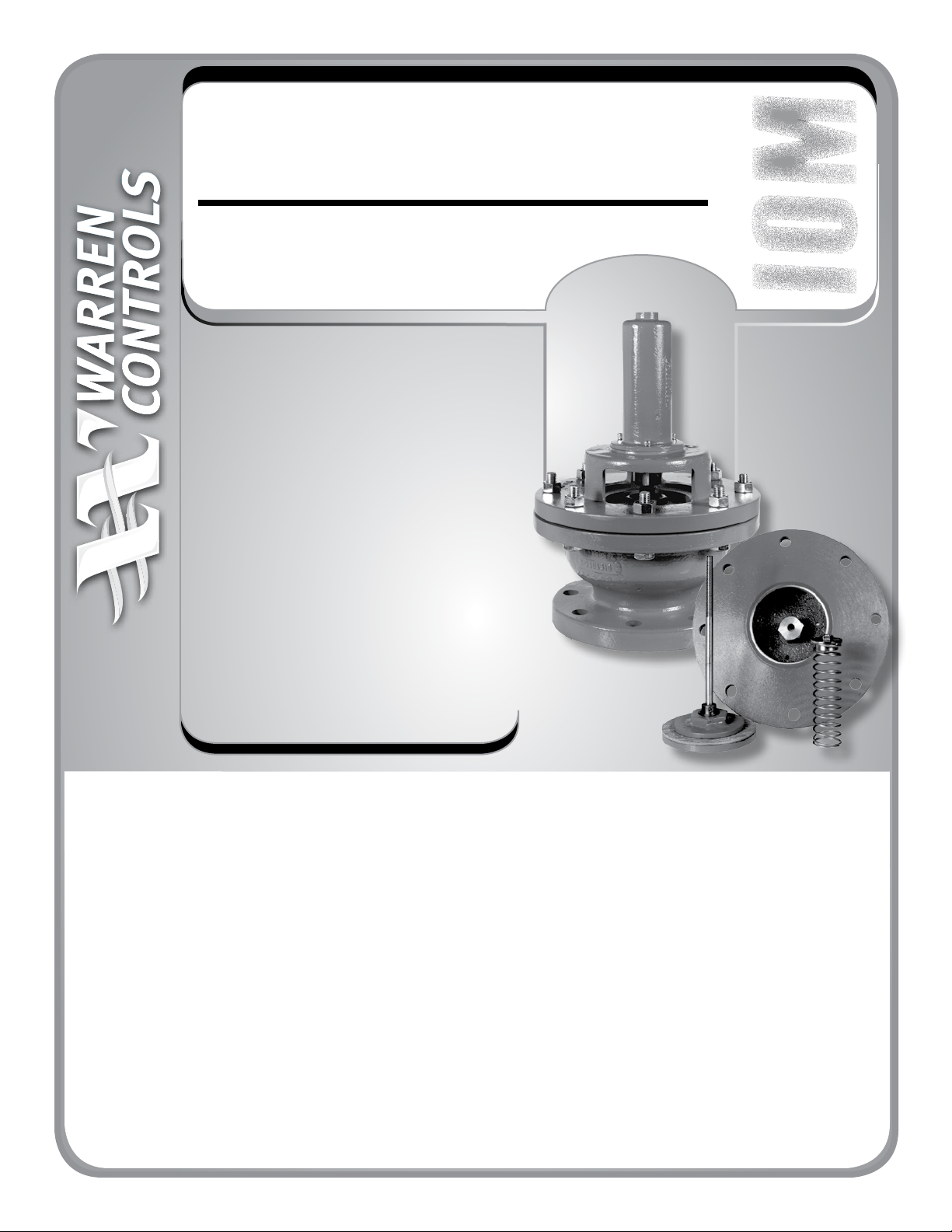
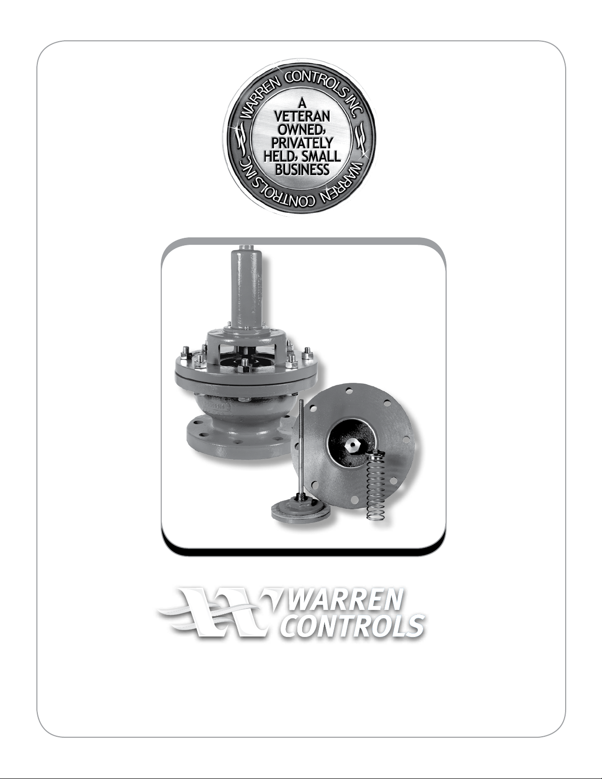
Type 200
Vacuu m Bre ak er
TABLE OF CONTENTS
Overview ........................................................ COVER
General Information ....................................... COVER
Installation .............................................................. 4
Operation ................................................................ 4
Maintenance ...........................................................4
Seat Inspection & Cleaning Procedures ................5
Opening Force Test & Adjustment
Procedures ............................................................. 6
Overhaul ..................................................................6
Information Present on
Vacuum Breaker ..................................................... 7
Type 200 Vacuum Breaker Specifications........8-10
Type 200 Vacuum Breaker Parts/Overhaul ........ 11
Parts Kits .........................................................12-13
Construction Drawing & Dimensions ...................14
PRODUCT OVERVIEW
This document covers the installation, operation and
maintenance of Type 200 presented in the “Level
Controls and Accessories”, Product Specication.
GENERAL INFORMATION
The instructions given herein cover generally the operation
and maintenance of subject equipment. Should any
questions arise which may not be answered specically
by these instructions, they should be referred to Warren
Controls Inc. for further detailed information and technical
assistance. This manual cannot possibly cover every situation
connected with the operation, adjustment, inspection, test,
overhaul and maintenance of the equipment furnished.
Every eort is made to prepare the text of this manual so
that engineering and design data is transformed into the
most easily understood wording. Warren Controls Inc., in
furnishing this equipment and this manual, must presume
that the operation and maintenance personnel assigned
thereto have sucient technical knowledge and experience
to apply sound safety and operational practices which
may not be covered herein. In applications where Warren
Controls Inc. furnished equipment is to be integrated with
a process or other machinery, these instructions should be
thoroughly reviewed to determine the proper integration of
the equipment into the overall plant operational procedures.
Warren Controls does not assume responsibility for
the selection, use, or maintenance of any product.
Responsibility for proper selection, use, and maintenance
of any Warren Controls product remains solely with the
purchaser and end-user
Page 2
WARNING!
CHECK VACUUM BREAKER FOR ANY
DAMAGE DUE TO IMPROPER STORAGE OR
TRANSPORTATION. IMMEDIATELY NOTIFY
YOUR SALES ORGANIZATION OF ANY
DAMAGED GOODS UPON RECEIPT. DO
NOT ATTEMPT TO MOVE OR DISTURB THE
VACUUM BRE AKER FURTHER SO PHOTOS MAY
BE TAKEN. IF THE SHIPPING CONTAINER IS
NOTICEABLY DAMAGED REFUSE RECEIPT, AS
THE SHIPPING COMPANY SHOULD BE HELD
LIABLE UNTIL A SHIPPING REPRESENTATIVE IS
AVAILABLE TO TAKE PHOTOS.
!!
2600 Emrick Blvd • Bethlehem, PA 18020 • USA •800-922-0085 • www.warrencontrols.com
2
Page 3
Warren Controls
Level Controls at Work...
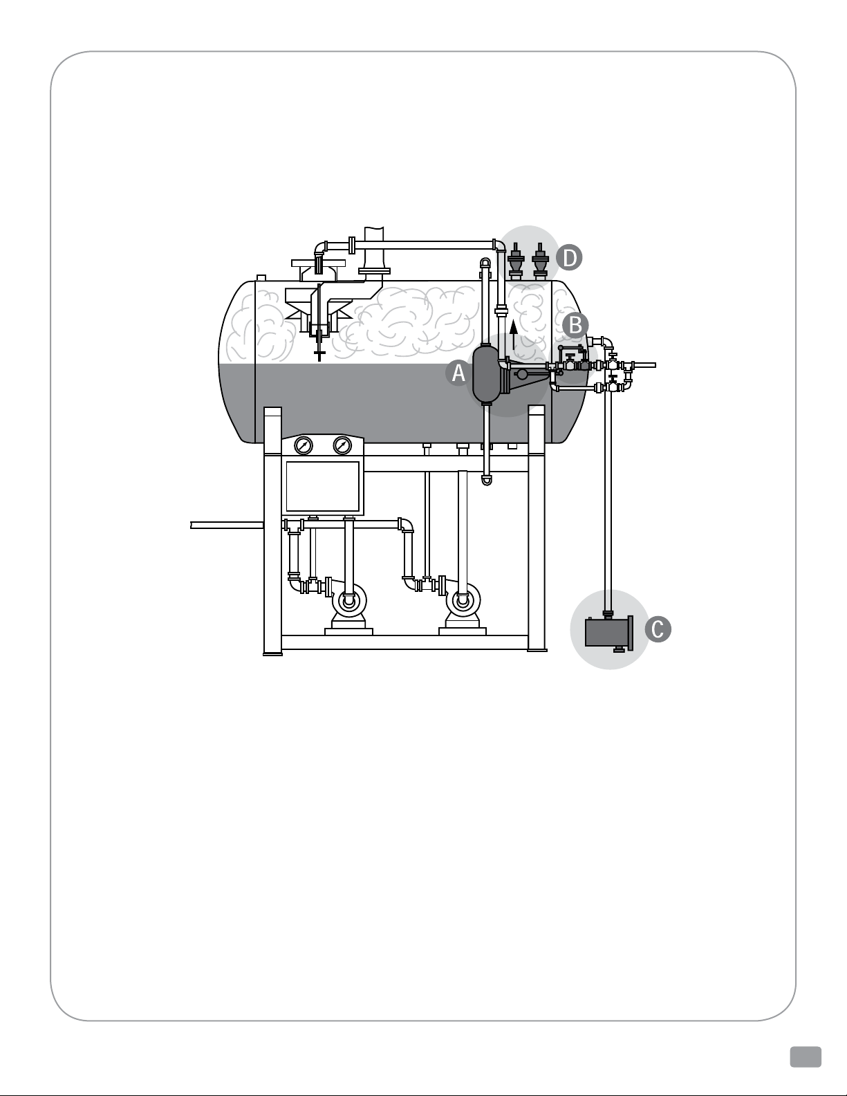
The following is a typical example of a tank filling/deaerator application using properly sized,
selected, and maintained Warren Controls Level Controls. Demand for water reduces the liquid
level in the tank. The [A] 377 Float Cage opens the [B] 322L or 326L Lever Valve to supply intake
water to the tank. When the water reaches the desired level the float cage closes the lever valve
to accurately maintain the liquid at the desired level. Deaerators, tanks with steam blankets,
produce additional liquid as the steam condenses. The [C] 313 Overflow Trap traps and relieves
this condensate through its internal pilot without the steam blanket escaping. Overflow can occur
if the water entering the tank exceeds its capacity. The 313 Overflow Trap relieves the overflow
through its internal single seated main stage valve. Falling liquid levels and condensing steam
can cause a vacuum that can damage the tank. The [D] Type 200 Vacuum Breaker opens to admit
outside air to relieve the vacuum in the tank. Warren Controls Level Controls are also used on boiler
make-up water tanks and many other storage tank applications.
Level COntrols - IOM 200 Vacuum Breaker 200_IOM_RevAa_1112
3
Page 4
INSTALLATION – TYPE 200
VACUUM BREAKER
• TodeterminewhichType200VacuumBreaker
you have, locate the part number on the
factory serial number label (See Information
Present on Type 200 section for location of
important information on vacuum breaker).
Then see Type 200 Specications section to
determine the performance and physical
characteristics of the vacuum breaker).
• Thevacuumbreakermustbeinstalledinthe
vertical position with its mounting connection
downward. A anged vessel mounting
connection must be a at surface to prevent
distortion of surfaces when the connection is
tight. A warped vessel mounting ange may
cause a leaky joint or break a cast iron Type
200 mounting ange.
• Eliminatevibration.Type200arenotsuitable
in installations where vibration exists.
• Before installing, be sure vacuum breaker
and piping are clean inside and free of scale,
chips, welding spatter, and foreign material.
Thoroughly blow out or ush pipe lines.
• Do not obscure factory serial number label
with paint.
OPERATION – TYPE 200 VACUUM BREAKER
• When no vacuum ispresentthevesselpressureacts on the vacuum breaker’sdischolderpressingthedisc
intotheseatsealingthetank’s/pipeline’scontentsinside.Whenthevesselpressuredropsbelowatmospheric
pressure a vacuum forms. The atmospheric pressure then acts on the discholder to overcome the force of the
vacuumbreaker’sspring.Theseatanddiscseparateadmittingoutsideair.TheType200VacuumBreakeropens
gradually to admit outside air to relieve the vacuum in the tank/ pipeline. The Type 200 Vacuum Breaker cannot
be preset to open at a particular setpoint.
MAINTENANCE – TYPE 200
VACUUM BREAKER
• Type200 for the most partaremaintenance
free when sized and chosen properly for the
application. Maintain the uid pressure and
temperature within the limits of the vacuum
breaker (See Information Present on Type 200
section for location of important information
on vacuum breaker and Type 200 Specications section for additional details).
2600 Emrick Blvd • Bethlehem, PA 18020 • USA •800-922-0085 • www.warrencontrols.com
4
• Openingsinadapterbodymustbe kept unblocked. The disc must be kept free of dirt
and debris. The disc must return freely to the
closed position if pushed away from the valve
body.
• Perform Seat Inspection during scheduled
maintenance periods. If necessary clean seat.
• Perform Opening Force Test during scheduled maintenance periods. If necessary adjust
opening force.
Page 5

SEAT INSPECTION AND CLEANING PROCEDURE:
1) Remove line or tank pressure and isolate vacuum breaker. (It is recommended that the vacuum breaker be removed
from the piping or tank for the seat inspection and cleaning procedure. It is recommended that you have an Inspection
Kit on hand before beginning the procedure.)
2) Remove nuts and bolts fastening valve body to adapter body.
3) Remove valve body from adapter body.
4) Remove capscrews from spring chamber.
5) Remove spring chamber from valve body.
6) Remove jamnuts from stem. Be careful, spring is preloaded.
7) Remove spring button.
8) For vacuum breakers with single spring remove spring. For vacuum breakers with dual springs remove
outer and inner springs.
9) Remove disc and stem assembly from valve body.
10) Clean gasket surfaces on valve body and adapter body.
11) Inspect the integral seat or seat ring in the valve body. The integral seat or seat ring must be clean and free from
deposits, scratches, or other damage. If deposits are present clean the seat with red (ne) crocus cloth and a
general purpose degreasing solvent. Cloths or pads containing ultra ne silicon carbide such as a Scotch-Brite
Ultra Fine Hand Pad or Norton Bear-Tex Clean & Finish Pad are also suitable for cleaning the seat. Clean the seat
with a circumferential motion around its diameter not with a longitudinal motion across its length. For vacuum
breakers with an integral seat, if after polishing the seat, you can still detect deposits, scratches, or other damage
with your ngernail , then replace the vacuum breaker. For vacuum breakers with a replaceable seat ring, if after
polishing the seat, you can still detect deposits, scratches, or other damage with your ngernail, then replace
the seat ring. For vacuum breakers with an integral seat, after cleaning, a light coat of primer may be applied to
protect the seat.
12) Install disc and stem assembly in valve body.
13) For vacuum breakers with single spring, install spring over stem and center spring over pilot on valve body.
For vacuum breakers with dual springs, install inner spring over stem. Install outer spring over stem and inner
spring. Center outer spring over pilot on valve body.
14) Install spring button on stem. Watch orientation. Center spring(s) over pilot(s) on spring button.
15) Install jamnuts on stem. DO NOT tighten until opening force is adjusted see following page.
16) Install new gasket on adapter body.
17) Install valve body on adapter body.
18) Install bolts through holes in adapter body and valve body. Install nuts on bolts. Tighten nuts and bolts in
increments in an alternating pattern.
19) Complete steps 4 thru 10 of Opening Force Adjustment Procedure.
Level COntrols - IOM 200 Vacuum Breaker 200_IOM_RevAa_1112
5
Page 6
OPENING FORCE TEST PROCEDURE:
1) Remove line or tank pressure and isolate vacuum breaker. (It is recommended that the vacuum breaker
be removed from the piping or tank for the test procedure)
2) Remove capscrews from spring chamber.
3) Remove spring chamber from valve body.
4) Apply water to cover top of disc.
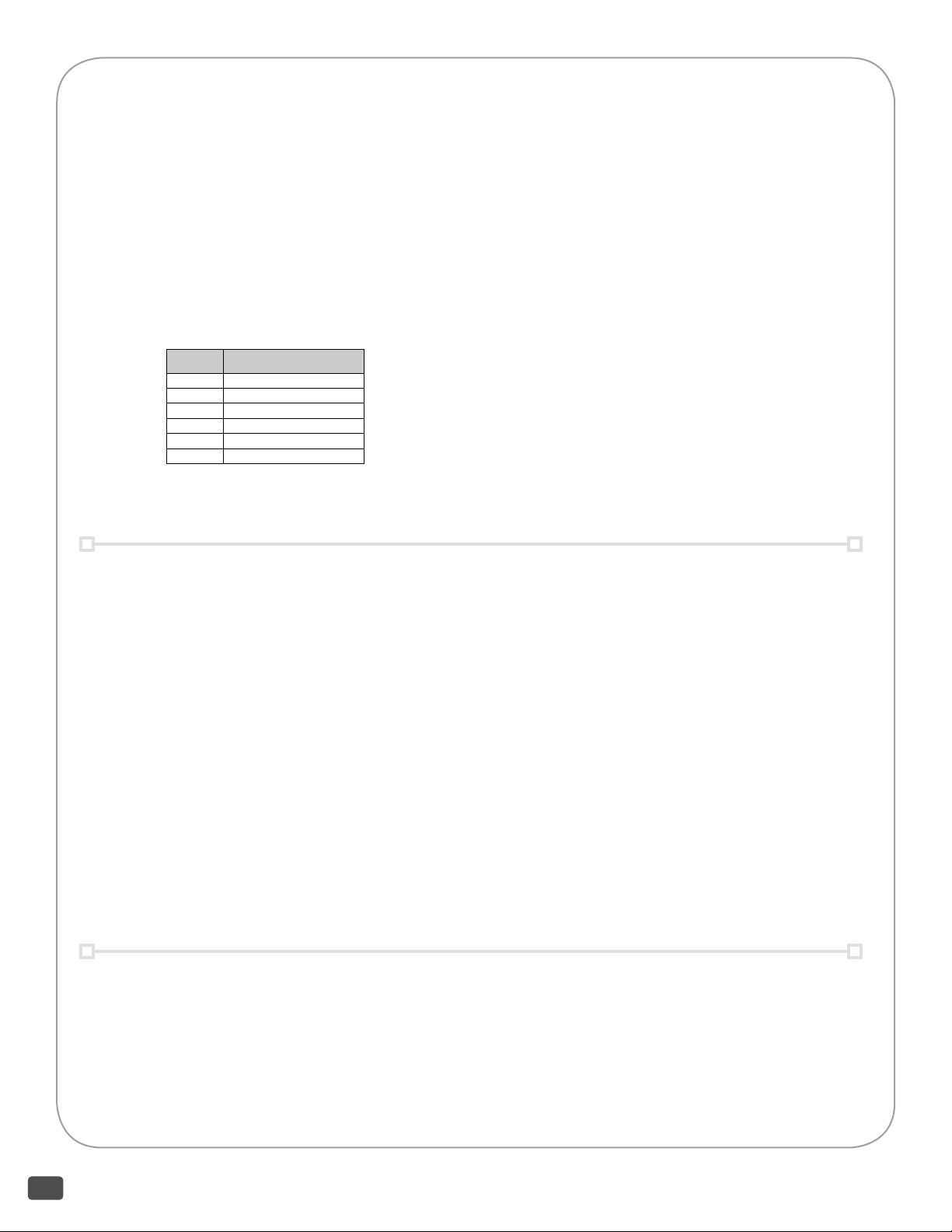
5) Refer to table below. Apply opening force to end of stem using dead weights. The seat must open
enough that it will not hold water applied above the disc retainer. The disc must return to contact
the seat when the weight is removed.
SIZE OPENING FORCE
2 2 POUNDS
4 5 POUNDS
6 15 POUNDS
8 15 POUNDS
10 20 POUNDS
12 30 POUNDS
OPENING FORCE ADJUSTMENT PROCEDURE:
1) Remove line or tank pressure and isolate vacuum breaker. (It is recommended that the vacuum breaker
be removed from the piping or tank for the adjustment procedure)
2) Remove capscrews from spring chamber.
3) Remove spring chamber from valve body.
4) Loosen jamnuts on stem until disc is not in contact with seat.
5) Tighten lower jamnut against spring button until disc remains in contact with seat.
6) Apply water to cover top of disc.
7) Set spring opening force. Refer to table in Opening Force Test Procedure. Apply opening force to
end of stem using dead weights. Adjust the position of the lower jamnut on the stem so the seat
opens enough that it will not hold water applied above the disc retainer; and the disc returns to
contact the seat when the weight is removed.
8) Tighten upper jamnut against lower jamnut.
9) Install spring chamber on valve body.
10) Install capscrews through holes in spring chamber. Tighten capscrews to secure spring chamber to
valve body.
OVERHAUL
Rebuilding of the vacuum breaker should not be necessary under normal operating
conditions. Should the vacuum breaker become worn or defective, parts kits are available.
See Parts/ Overhaul.
2600 Emrick Blvd • Bethlehem, PA 18020 • USA •800-922-0085 • www.warrencontrols.com
6
Page 7
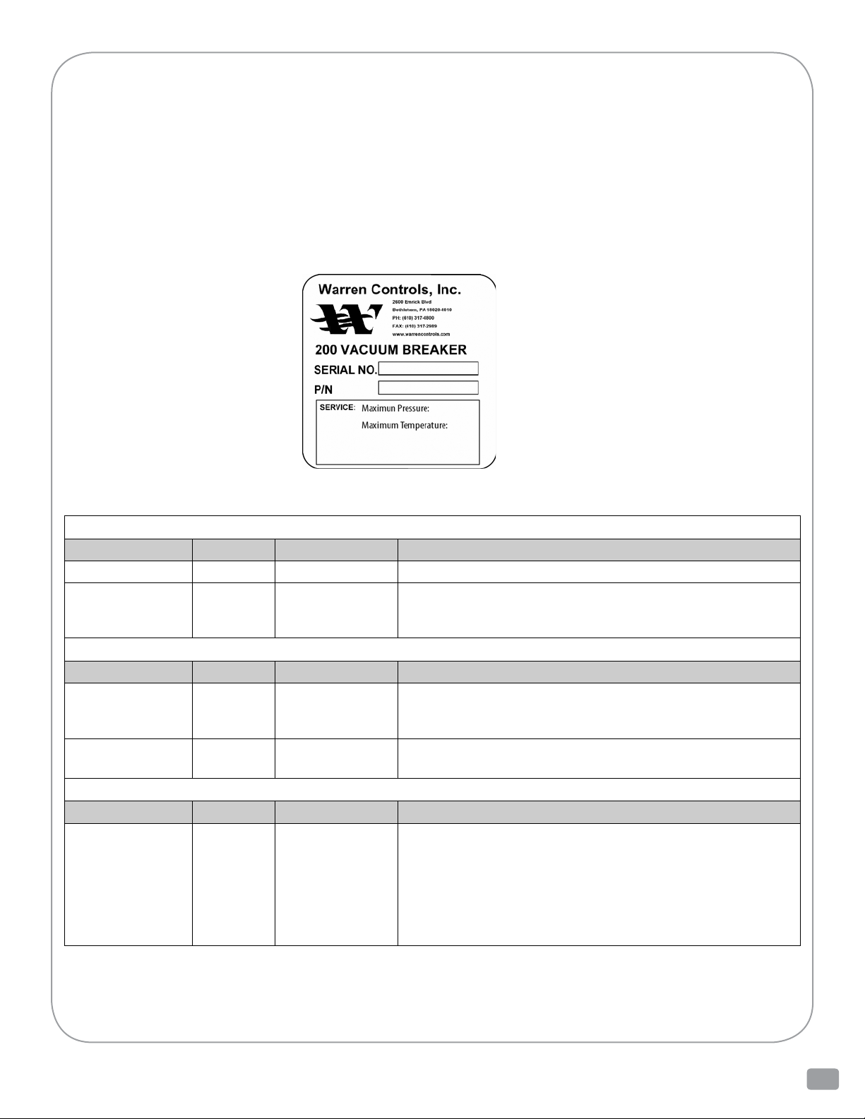
INFORMATION PRESENT ON TYPE 200 VACUUM BREAKER
There is information present on each vacuum breaker ranging in importance from the part number and serial
number to the color of the paint and casting numbers. This information is important for identifying the vacuum
breaker, installing it correctly, and obtaining parts. An example of the current factory serial number label
used on Type 200 Vacuum Breakers is shown here. The accompanying table identies the information present
and where to nd it on the vacuum breaker. There may also be other casting numbers and foundry marks present
that do not provide useful information. Customer specic tagging may also present. The labels or plates used,
and information present, on Warren Controls other product lines or older vacuum breakers may be dierent,
contact the factory for details.
FACTORY SERIAL
NUMBER LABEL
INFORMATION PRESENT ON Type 200
PART NUMBER & SERIAL NUMBER
INFORMATION SYMBOLS LOC ATION NOTES
Part number
Serial Number
P/N
SERIAL NO.
On spring chamber
On spring chamber
and valve body
• On Factory Serial Number Label attached to spring chamber.
• On Factory Serial Number Label attached to spring chamber.
• Sales order number only stamped on valve body end connection.*
* Number stamped using approximately 1/8 inch tall characters
SERVICE
INFORMATION SYMBOLS LOC ATION NOTES
Maximum
pressure rating
Maximum
temp. rating
Maximum
Pressure
Maximum
Temperature
On spring chamber
On spring chamber
• On Factory Serial Number Label attached to spring chamber.
• On Factory Serial Number Label attached to spring chamber.
VALVE ATTRIBUTES
INFORMATION SYMBOLS LOC ATION NOTES
Body material On vacuum
breaker
• If the factory applied paint is black and the adapter
body is cast in one piece the body material is iron.
• If the factory applied paint is black and the adapter body is made
of three sections welded together the body material is steel.
• If there is no factory applied paint present and the adapter body
is made of three sections welded together the body material
is stainless steel.
Level COntrols - IOM 200 Vacuum Breaker 200_IOM_RevAa_1112
7
Page 8
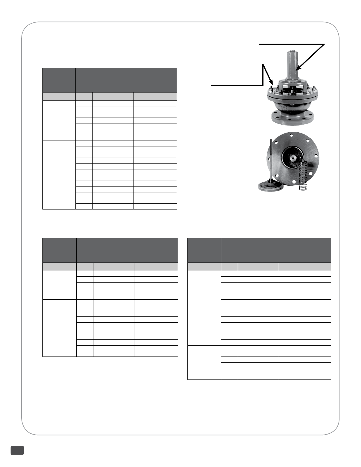
TYPE 200 VACUUM BREAKER SPECIFICATIONS
VACUUM BREAKERS WITH NON-ASBESTOS DISC
Serial number label located here
200
With Standard Trim
(Integral Seat, Non-Asbestos
Disc and Steel Discholder)
Body Material
IRON
STEEL
STEEL
* 2” Type 200 has stainless steel discholder - standard
200
Size End Connection Part Number
2* 125FLG 020009EXX000
2* NPT 020009IXX000
4 125FLG 020013EXX000
6 125FLG 020015EXX000
8 125FLG 020017EXX000
10 125FLG 020019EXX000
12 125FLG 020020EXX000
2* 150FLG 020009GXX000
4 150FLG 020013GXX000
6 150FLG 020015GXX000
8 150FLG 020017GXX000
10 150FLG 020019GXX000
12 150FLG 020020GXX000
2* 300FLG 020009HXX000
4 300FLG 020013HXX000
6 300FLG 020015HXX000
8 300FLG 020017HXX000
10 300FLG 020019HXX000
12 300FLG 020020HXX000
With Integral Seat,
Non-Asbestos Disc and
Stainless Steel Discholder
Body Material
IRON
STEEL
STEEL
Size End Connection Part Number
4 125FLG 020013EXX005
6 125FLG 020015EXX005
8 125FLG 020017EXX005
10 125FLG 020019EXX005
12 125FLG 020020EXX005
4 150FLG 020013GXX005
6 150FLG 020015GXX005
8 150FLG 020017GXX005
10 150FLG 020019GXX005
12 150FLG 020020GXX005
4 300FLG 020013HXX005
6 300FLG 020015HXX005
8 300FLG 020017HXX005
10 300FLG 020019HXX005
12 300FLG 020020HXX005
Sales order (serial)
number stamped here
200
Body Material
IRON
STEEL
STEEL
4” Iron Type 200
Stainless steel stem and non-asbestos
disc assembly, Iron body with seat and
brass guide, and stainless steel spring
assembly shown separately
With Non-Asbestos Disc and Stainless
Steel Trim (SS Discholder and
SS Replaceable Seat)
Size End Connection Part Number
2 125FLG 020009EXX006
2 NPT 020009IXX006
4 125FLG 020013EXX006
6 125FLG 020015EXX006
8 125FLG 020017EXX006
10 125FLG 020019EXX006
12 125FLG 020020EXX006
2 150FLG 020009GXX006
4 150FLG 020013GXX006
6 150FLG 020015GXX006
8 150FLG 020017GXX006
10 150FLG 020019GXX006
12 150FLG 020020GXX006
2 300FLG 020009HXX006
4 300FLG 020013HXX006
6 300FLG 020015HXX006
8 300FLG 020017HXX006
10 300FLG 020019HXX006
12 300FLG 020020HXX006
2600 Emrick Blvd • Bethlehem, PA 18020 • USA •800-922-0085 • www.warrencontrols.com
8
Page 9
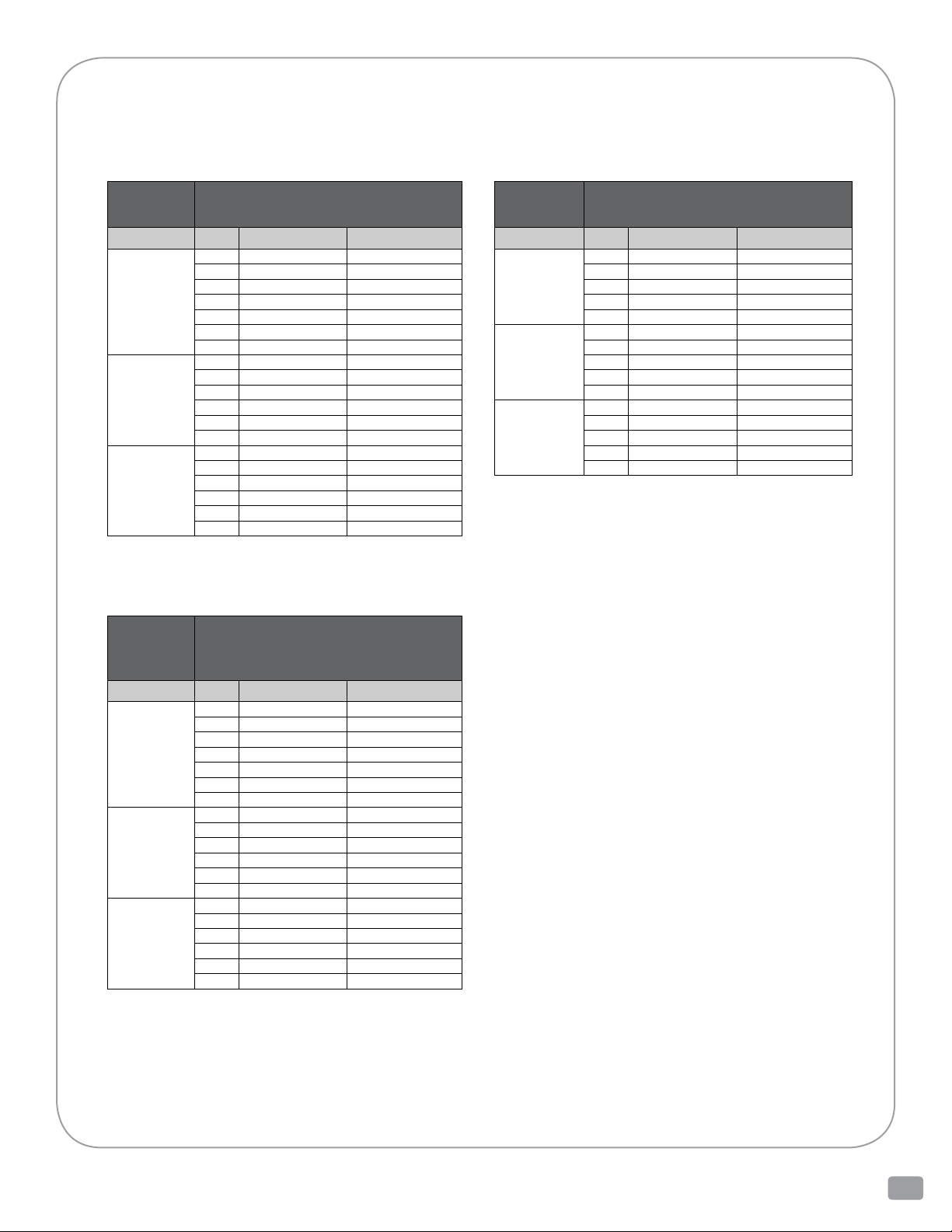
TYPE 200 VACUUM BREAKER SPECIFICATIONS
VACUUM BREAKERS WITH TEFLON DISC
200
With Integral Seat, Teflon Disc,
And Steel Discholder
Body Material Size End Connection Part Number
IRON
STEEL
STEEL
* 2” Type 200 has stainless steel discholder - standard
200
2* 125FLG 020009EXX001
2* NPT 020009IXX001
4 125FLG 020013EXX001
6 125FLG 020015EXX001
8 125FLG 020017EXX001
10 125FLG 020019EXX001
12 125FLG 020020EXX001
2* 150FLG 020009GXX001
4 150FLG 020013GXX001
6 150FLG 020015GXX001
8 150FLG 020017GXX001
10 150FLG 020019GXX001
12 150FLG 020020GXX001
2* 300FLG 020009HXX001
4 300FLG 020013HXX001
6 300FLG 020015HXX001
8 300FLG 020017HXX001
10 300FLG 020019HXX001
12 300FLG 020020HXX001
With Teflon Disc, and Stainless
Steel Trim (SS Discholder and
SS Replaceable Seat)
Body Material Size End Connection Part Number
IRON
STEEL
STEEL
2 125FLG 020009EXX004
2 NPT 020009IXX004
4 125FLG 020013EXX004
6 125FLG 020015EXX004
8 125FLG 020017EXX004
10 125FLG 020019EXX004
12 125FLG 020020EXX004
2 150FLG 020009GXX004
4 150FLG 020013GXX004
6 150FLG 020015GXX004
8 150FLG 020017GXX004
10 150FLG 020019GXX004
12 150FLG 020020GXX004
2 300FLG 020009HXX004
4 300FLG 020013HXX004
6 300FLG 020015HXX004
8 300FLG 020017HXX004
10 300FLG 020019HXX004
12 300FLG 020020HXX004
200
With Integral Seat, Teflon Disc
And Stainless Steel Discholder
Body Material Size End Connection Part Number
IRON
STEEL
STEEL
4 125FLG 020013EXX002
6 125FLG 020015EXX002
8 125FLG 020017EXX002
10 125FLG 020019EXX002
12 125FLG 020020EXX002
4 150FLG 020013GXX002
6 150FLG 020015GXX002
8 150FLG 020017GXX002
10 150FLG 020019GXX002
12 150FLG 020020GXX002
4 300FLG 020013HXX002
6 300FLG 020015HXX002
8 300FLG 020017HXX002
10 300FLG 020019HXX002
12 300FLG 020020HXX002
Level COntrols - IOM 200 Vacuum Breaker 200_IOM_RevAa_1112
9
Page 10
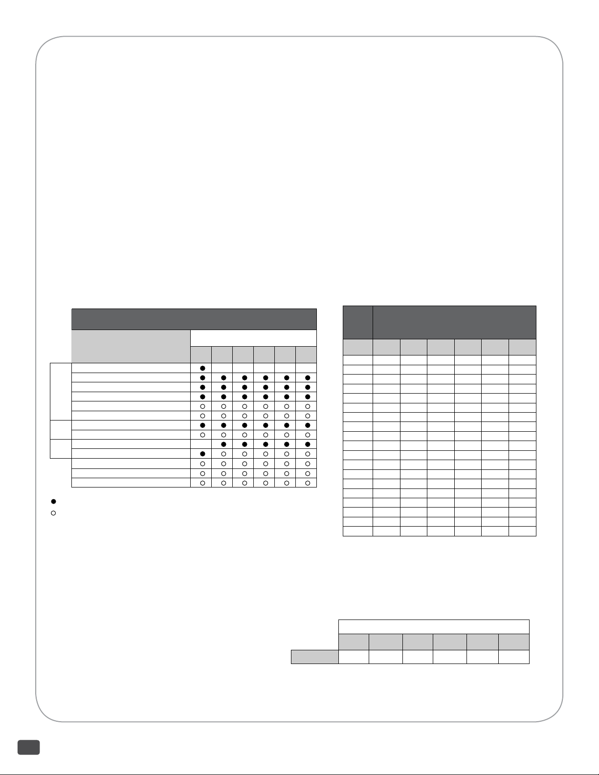
TYPE 200 VACUUM BREAKER SPECIFICATIONS
APPLICATION:
Falling liquid levels and condensing steam can
cause a vacuum that can damage a tank. The Type
200 Vacuum Breaker opens gradually to admit
outside air to relieve the vacuum in the tank. The
unit must be installed vertically with its mounting
connection downward.
FEATURES:
Iron, steel, or stainless steel body; Iron, steel, or
stainless steel seat; Non-asbestos or TFE disc;
Size 2” iron with NPT or 125FLG connections,
2” steel and stainless steel with 150 or 300FLG;
4” through 12” iron with 125FLG,
4” through 12” steel and stainless steel with 150 or
300FLG
Air relief capacities to 14,280 CFM
SeeWhat’sAvailableChartforFeatures
What’s Available 200
Features Size (IN)
2 4 6 8 10 12
125 THD (NPT) IRON/ IRON
125 FLG IRON/ IRON
150 FLG STL/ STL
300 FLG STL/ STL
150 FLG ST STL/ ST STL
Body/ Seat
300 FLG ST STL/ ST STL
NON-ASBESTOS
Disc
TFE (TO 200 °F)
er
STEEL
ST STEEL
Disc-
hold
REPLACEABLE SEAT ST STEEL
BIRDSCREEN
LIFT RINGS
STANDARD
OPTION
PRESSURE-TEMPERATURE RATINGS:
Body: Iron
End Connection: 125THD (NPT) and 125FLG
Disc: Non-asbestos
Maximum Pressure: 50 PSIG
Maximum Temperature: 300F
Body: Steel or Stainless Steel
End Connection: 150FLG
Disc: Non-asbestos
Maximum Pressure: 150 PSIG
Maximum Temperature: 500F
Body: Steel or Stainless Steel
End Connection: 300FLG
Disc: Non-asbestos
Maximum Pressure: 300 PSIG
Maximum Temperature: 500F
AIR RELIEF CAPACITIES:
Vacuum
Inches Of
Mercury
The Type 200 cannot be set to open at a
particular vacuum.
The vacuum values presented in the table are
for reference only.
CFM OF FREE AIR ADMITTED AT 60F 200
Size (IN)
2 4 6 8 10 12
0.75 88 352 792 1408 2200 3300
0.80 94 376 846 1504 2350 3525
0.85 106 424 934 1696 2650 3975
1.15 126 504 1128 2016 3150 4725
1.25 148 592 1332 2298 3700 5550
1.65 162 648 1458 2592 4050 6780
2.30 188 752 1692 3008 4700 7050
4.00 226 904 2034 3616 5650 8475
4.45 236 944 2124 3776 5900 8850
6.05 268 1072 2412 4288 6700 10050
6.30 276 1104 2484 4416 6900 10350
8.10 300 1200 2700 4800 7500 11250
8.65 314 1256 2826 5024 7850 11775
11.30 334 1336 3006 5344 8350 12525
12.05 348 1392 3132 5568 8700 13050
16.05 370 1480 3330 5920 9250 13875
16.65 372 1488 3348 5952 9300 13950
18.50 386 1541 3481 6189 9670 14505
19.10 381 1523 3427 6093 9520 14280
WEIGHTS:
Valve Size (IN)
2 4 6 8 10 12
Weight (lb) 26 68 102 180 230 375
For dimensions see drawing 0200032510.
2600 Emrick Blvd • Bethlehem, PA 18020 • USA •800-922-0085 • www.warrencontrols.com
10
Page 11

TYPE 200 VACUUM BREAKER PARTS/ OVERHAUL
Damaged or worn parts can decrease performance and shorten the life of the vacuum breaker.
A damaged or worn gasket can cause external leakage and damage to surrounding equipment.
A damaged or worn spring can result in a vacuum breaker that does not close when the vacuum in
atankisrelievedallowingthetank’scontentstoescapeanddamagesurroundingequipment,and
can also cause damage to the stem.
A damaged or worn stem can result in a vacuum breaker that does not open to relieve a vacuum
in a tank or close when the vacuum is relieved allowing the contents to escape and damage
surrounding equipment, and can also cause damage to the stem guide.
A damaged or worn stem guide can result in a vacuum breaker that does not open to relieve a
vacuum in a tank or close when the vacuum is relieved allowing the contents to escape and damage
surrounding equipment, and can also cause damage to the stem.
A damaged or worn connecting pin, disc, disc retainer, or disc holder can cause external leakage
resulting in the loss of the contents from the tank and damage to surrounding equipment, and can
also cause damage to surrounding parts inside the vacuum breaker.
A damaged or worn integral seat or seat ring can cause external leakage resulting in the loss of
the contents from the tank and damage to surrounding equipment, and can also cause damage to
the disc and disc holder.
Two dierent parts kits are available. An Inspection kit is available to allow a vacuum breaker to
be opened to inspect its internal parts. A rebuild kit is available to allow a vacuum breaker to be
overhauled. Please provide serial number to get the correct kit part numbers.
Level COntrols - IOM 200 Vacuum Breaker 200_IOM_RevAa_1112
11
Page 12
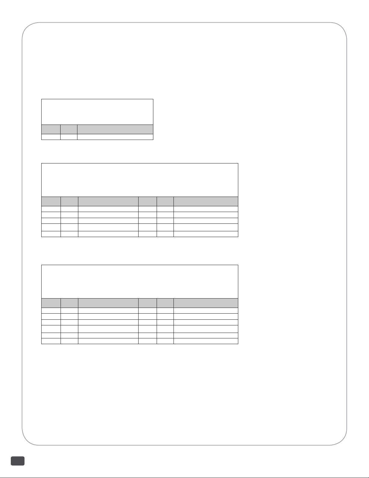
TYPE 200 VACUUM BREAKER PARTS KITS
The inspection kit allows a vacuum breaker to be opened so the condition of its internal parts may be inspected.
The rebuild kits allow a vacuum breaker to be overhauled.
(Provide vacuum breaker serial number to get kit part numbers)
INSPECTION KIT FOR TYPE 200 VACUUM
BREAKER
SEE DWG 0200032510
ITEM QTY DESCRIPTION
12 1 GASKET
REBUILD KIT
FOR TYPE 200 VACUUM BREAKER WITH INTEGRAL SEAT
AND SINGLE SPRING SIZE 2 THRU 12 INCH
SEE DWG 0200032510
ITEM QTY DESCRIPTION ITEM QTY DESCRIPTION
1 2 JAMNUT 9 1 CONNECTING PIN
2 1 SPRING BUTTON 10 1 DISC RETAINER
3 1 SPRING 12 1 GASKET
5 1 STEM 14 1 DISC HOLDER
7 1 STEM GUIDE 15 1 DISC
SIZE 2 THRU 12 INCH
REBUILD KIT
FOR TYPE 200 VACUUM BREAKER WITH INTEGRAL SEAT
AND DUAL SPRING SIZE 10 & 12 INCH EFFECTIVE DATE: 9/26/2008
SEE DWG 0200032510
ITEM QTY DESCRIPTION ITEM QTY DESCRIPTION
1 2 JAMNUT 10 1 DISC RETAINER
2 1 SPRING BUTTON 12 1 GASKET
3 1 OUTER SPRING 14 1 DISC HOLDER
5 1 STEM 15 1 DISC
7 1 STEM GUIDE 18 1 INNER SPRING
9 1 CONNECTING PIN
2600 Emrick Blvd • Bethlehem, PA 18020 • USA •800-922-0085 • www.warrencontrols.com
12
Page 13
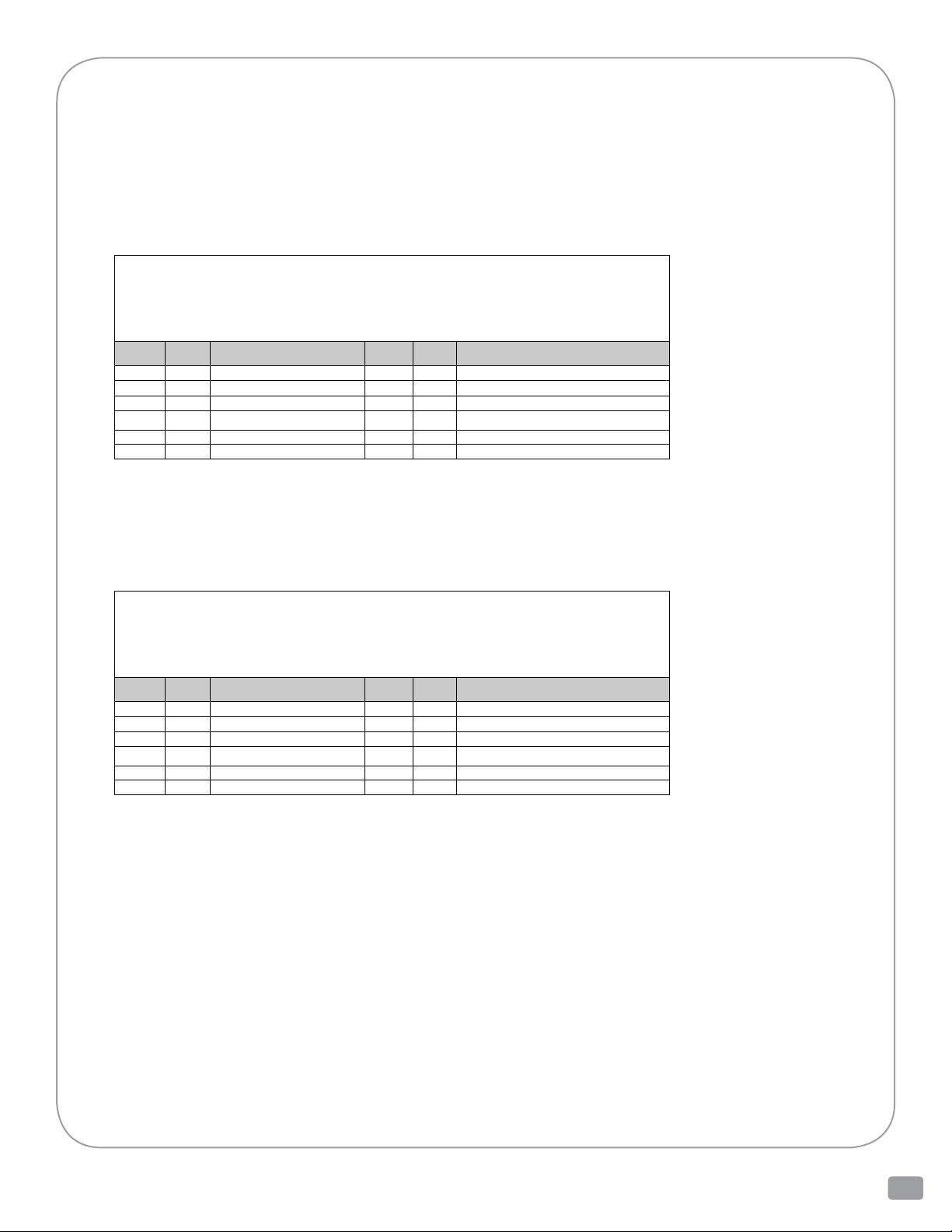
REBUILD KIT
FOR
TYPE
200 VACUUM BREAKER WITH REPLACEABLE SEAT AND SINGLE SPRING
SIZE 2 THRU 12 INCH
SEE DWG 0200032510
ITEM QTY DESCRIPTION ITEM QTY DESCRIPTION
1 2 JAMNUT 10 1 DISC RETAINER
2 1 SPRING BUTTON 12 1 GASKET
3 1 SPRING 14 1 DISC HOLDER
5 1 STEM 15 1 DISC
7 1 STEM GUIDE 17 1 SEAT RING
9 1 CONNECTING PIN
REBUILD KIT
FOR
TYPE
200 VACUUM BREAKER WITH REPLACEABLE SEAT AND DUAL SPRING
SIZE 10 & 12 INCH EFFECTIVE DATE: 9/26/2008
SEE DWG 0200032510
ITEM QTY DESCRIPTION ITEM QTY DESCRIPTION
1 2 JAMNUT 10 1 DISC RETAINER
2 1 SPRING BUTTON 12 1 GASKET
3 1 OUTER SPRING 14 1 DISC HOLDER
5 1 STEM 15 1 DISC
7 1 STEM GUIDE 17 1 SEAT RING
9 1 CONNECTING PIN 18 1 INNER SPRING
Level COntrols - IOM 200 Vacuum Breaker 200_IOM_RevAa_1112
13
Page 14
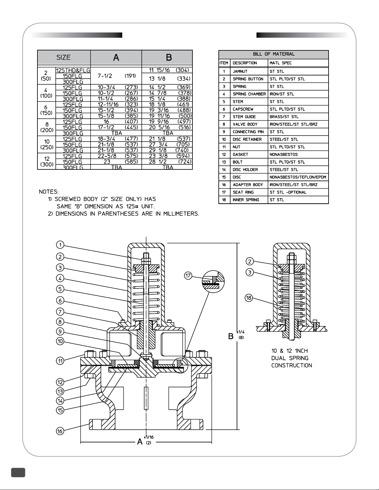
DRAWING 0200032510
2600 Emrick Blvd • Bethlehem, PA 18020 • USA •800-922-0085 • www.warrencontrols.com
14
Page 15
NOTES
Level COntrols - IOM 200 Vacuum Breaker 200_IOM_RevAa_1112
15
Page 16
200_IOM_RevAa_1112
 Loading...