

Page 1
P-2018
ZRC/ARC
ZRC Clutch / ARC Top Load
Service & Installation Instructions
An Altra Industrial Motion Company
Page 2
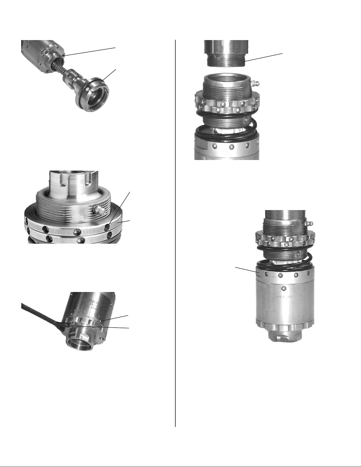
ARC Installation Procedure
Wrench ats
Customer
Supplied Chuck
Figure 1
Install chuck (not supplied). Use appropriate openend wrench (YTL4-0005, YTL4-0008, YTL4-0010)
depending on headset model to hold headset
output. See Figure 1.
Spanner
Holes
Apply Anti-seize
Figure 4
Apply anti-seize compound to spindle shaft. Install
headset on spindle. Turn onto threaded spindle until
headset is fully seated on spindle. See Figure 4.
Jam Nuts
Figure 2
Set the top-load assembly using provided spring
setting chart. Lock the jam nuts using O.D. spanner
wrenches with 1/4” pins (YTL3-0009). See Figure 2.
Set Screws
Face
Spanner
Wrench
Figure 3
Set the preliminary static torque using provided
torque setting chart. Loosen set screws with hex
key wrench, turn end cap with face spanner wrench
(YTL2-0002). Tighten set screws to 8-10 lb-in. Over
tightening is not necessary and will strip the screws
or possibly damage the housing body. See Figure 3.
Spanner Holes
Figure 5
Install headset on spindle. Turn onto threaded
spindle until headset is fully seated on spindle.
Tighten headset securely using O.D. Spanner
wrench (YTL3-0009). See Figure 5.
2 Warner Electric • 800-825-9050 P-2018 • ZRC/ARC
Page 3
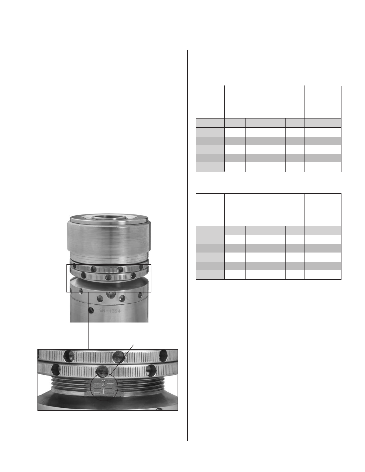
Setting Top Load Spring Force
1. Determine initial spring setting from spring force
chart below.
2. Compress the spring with the locking ring just
enough to allow the adjustment ring into its correct
setting.
3. Move the adjustment ring to the desired setting.
Bring the locking ring down and jam the rings
together with a spanner wrench.
4. For optimum results check download force with a
force scale.
5. Set headset on the scale and manually compress
the spring downward 5mm. Take the force reading
at this position. The lines on the spring cover
are .100” (2.5mm) apart, so two lines equal the
recommended .200” (5mm) compression.
Top Load Spring Force
Setting Chart
Spring Force at 0.200” (5mm) Deection
Standard
Spring
Setting
lb Kg lb Kg lb Kg
1.0 34 15 24 11 50 23
1.5 39 18 27 12 58 26
2.0 44 20 31 14 66 30
2.5 49 22 34 15 73 33
Max 54 24 38 17 80 37
Spring
YTP1-0010
Plain
Spring Force at 0.100” (2.5mm) Deection
Standard
Spring
Setting
Spring
YTP1-0010
Plain
Low
Spring
YTP1-0003
Grey
Low
Spring
YTP1-0003
Grey
High
Spring
YTP1-0008
Black
High
Spring
YTP1-0008
Black
Top Load Settings
lb Kg lb Kg lb Kg
1.0 29 13 20 9 43 20
1.5 34 15 24 11 50 23
2.0 39 18 27 12 58 26
2.5 44 20 31 14 66 30
Max 49 22 34 15 73 33
NOTE: The charts above provide actual spring
loads without any added load due to the
weight of the headset. These spring loads are
valid for any headset. Not all headsets have
the full range of settings; some headsets do
not have a ‘3.0’ setting, other headsets do not
have ‘1.0’ or ‘1.5’ settings. The spring loads
are calculated at the given deection as listed
in the chart.
Figure 6
Warner Electric • 800-825-9050 P-2018 • ZRC/ARC 3
Page 4
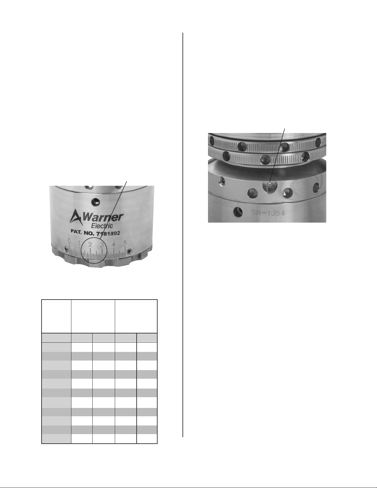
Setting Application Torque
1. Determine initial clutch setting from torque chart
below.
Recommended Maintenance
Schedule
Lubricate the upper assembly every 500 hours
of run time.
2. Loosen the torque adjustment screws. Rotate the
adjustment ring using the face spanner wrench to
the desired setting and then retighten the torque
adjustment screws. Do not use the set screw in
the slot on the backside of the housing for torque
adjustment. Tighten set screws to 8-10 lb-in.
Over tightening is not necessary and will strip the
screws or possibly damage the housing body.
3. For optimum results, check setting with a torque
wrench and FIX-0007 or FIX-0010.
Application
Torque Setting
Figure 7
- Using a grease injector needle, apply lubricant into
the grease port.
- Recommended grease: No. 2 Food Grade Grease
Grease Port
Figure 8
Disassemble, clean, and replace all wearing
parts in the headset every 7000 hours of
machine run time.
Application Torque Setting Charts
Application
Clutch
Setting
lb-in Ncm lb-in Ncm
0.00 2.00 22.5 6.0 67.8
0.50 3.50 39.5 7.0 79.1
1.00 5.00 56.5 8.0 90.4
1.50 8.50 96.0 11.5 129.9
2.00 10.50 118.6 14.0 158.2
2.50 13.50 152.5 16.0 180.8
3.00 16.00 180.7 21.0 237.3
3.50 17.50 197.7 23.5 265.5
4.00 18.50 209.0 25.5 288.1
4.50 19.00 214.6 28.0 316.4
5.00 19.50 220.3 29.5 333.3
Torque-Low
Inertia
Magnet
Application
Torque (Ncm)
Standard
Magnet
- See rebuild instructions for detailed information on
disassembly and assembly of Warner headsets.
- Dependent upon machine speed and washdown
procedure, some environments may require more
frequent rebuilds.
Rebuild Kits available:
• M4.5-BK (Bearing and Hardware Rebuild Kit)
• M4.5-MK (Magnet Rebuild Kit)
• M4.5-PK (Push rod Rebuild Kit)
• M4.5-TL (Replacement Top Load Assembly)
*Contact customer service for the exact kit part
number for your specific headset model.
4 Warner Electric • 800-825-9050 P-2018 • ZRC/ARC
Page 5
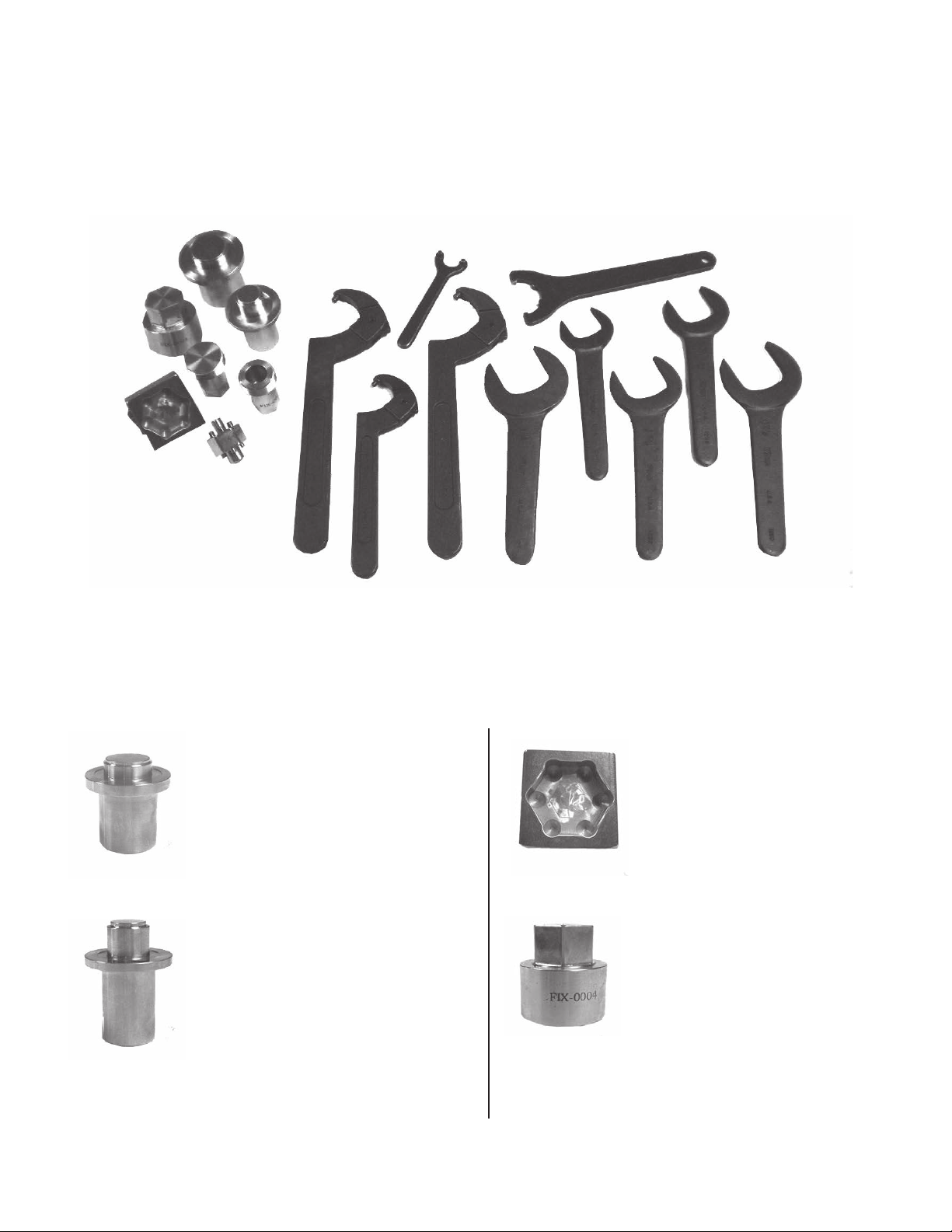
Installation Tools and Fixtures
FIX-0001 – Bearing installation
and removal fixture for the ZRC
style bearings.
FIX-0003 – Use to hold the
output of ARC style unit during
disassembly. Earlier revision levels
with a larger output dimension
Figure 10
Figure 12
FIX-0002 – Bearing installation
and removal fixture for the ARC
that will not fit in this fixture can
be clamped directly in a vice.
FIX-0004 – Upper assembly nut
removal fixture for ZRC style unit.
style bearing.
Figure 11
Warner Electric • 800-825-9050 P-2018 • ZRC/ARC 5
Figure 13
Continued on page 6.
Page 6
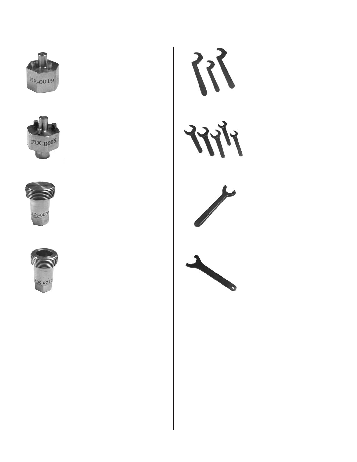
Tool Kit Component Parts Cont.
Figure 14
Figure 15
FIX-0019 – Clutch nut removal
xture for some ZRC style units.
Not included in tool kits. May be
ordered on an as-needed basis.
FIX-0005 – Upper assembly nut
removal xture for ARC style
unit.
FIX-0007 – Torque checking
xture for some ARC models.
Figure 18
Figure 19
YTL3-0009 (Qty 2) &
YTL3-0008 – Adjustable
O.D. Spanner Wrenches
used for adjusting top load
and separating top load and
clutch body.
YTL4-0009, YTL4-0005,
YTL4-0008, YTL4-0010,
YTL4-0007 – Open end
wrenches used to install
and remove chucks on
several ARC & ZRC models.
YTL2-0002 – Face
Spanner Wrench for
adjusting end cap and
setting static torque on
ARC & ZRC units.
Figure 16
Figure 17
FIX-0010 – Torque checking
xture for some ARC & ZRC
models.
Figure 20
Figure 21
YTL3-0005 – ER-25
Spanner Wrench used for
upper assembly adapter
removal for some ZRC style
units.
6 Warner Electric • 800-825-9050 P-2018 • ZRC/ARC
Page 7
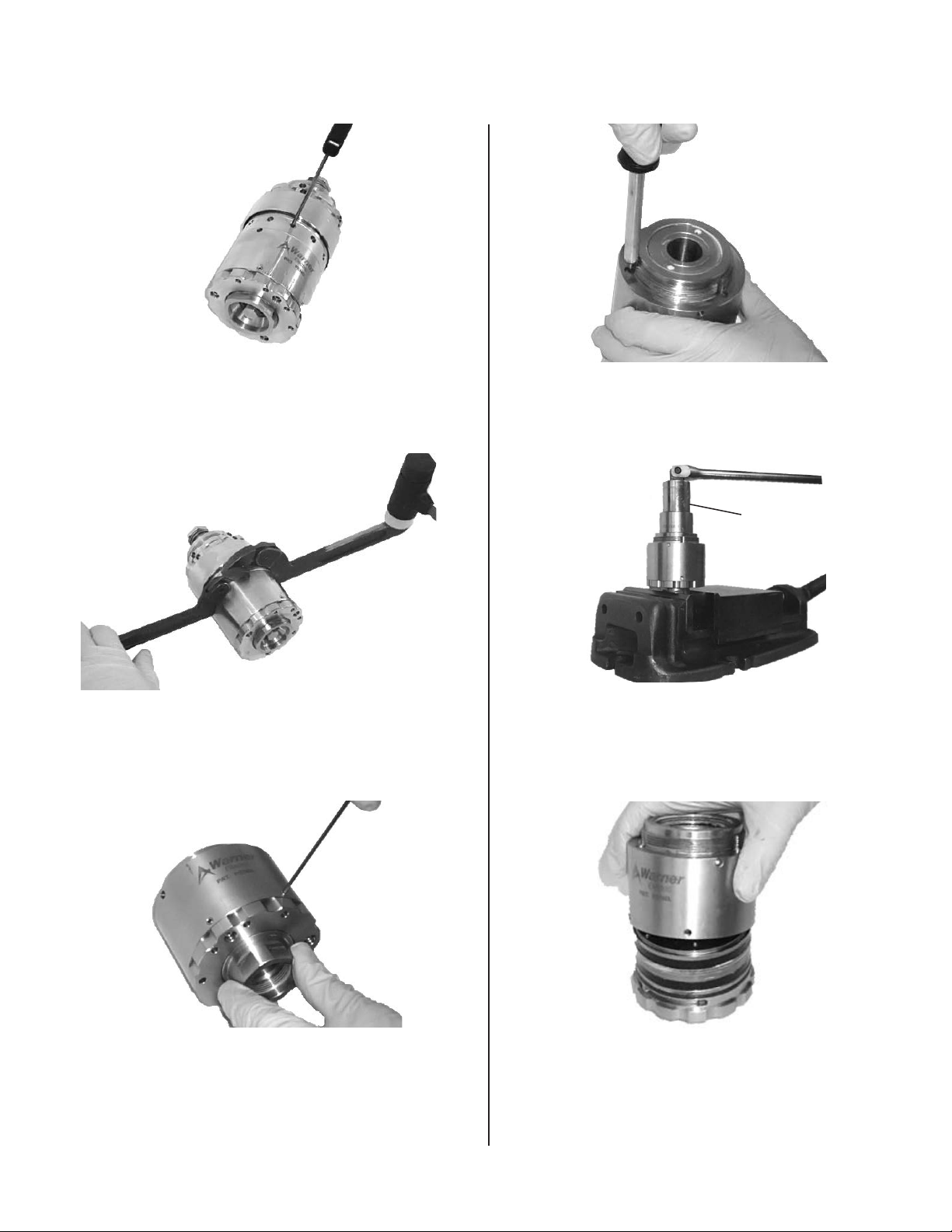
ZRC
Clutch Rebuild Procedure
Figure 22
With a 1/8” 3mm hex wrench, loosen the set
screw that holds the top load assembly and clutch
together. See Figure 22.
Figure 23
Using Spanner wrenches (YTL3-0009 & YTL3-0008)
and soft hammer, separate the clutch from the top
load assembly. See Figure 23.
Figure 25
Remove the three torx screws using a T-15 security
torx bit. See FIgure 25.
FIX-0004
Figure 26
Place chuck output shaft in vice, clamping on flats.
Using a socket, FIX-0004, and a breaker bar, remove
ring nut on top of clutch. See Figure 26.
Figure 24
Remove two set screw with a 3/32” 3mm hex
wrench. See Figure 24.
Warner Electric • 800-825-9050 P-2018 • ZRC/ARC 7
Remove housing from clutch. See Figure 27.
Figure 27
Page 8
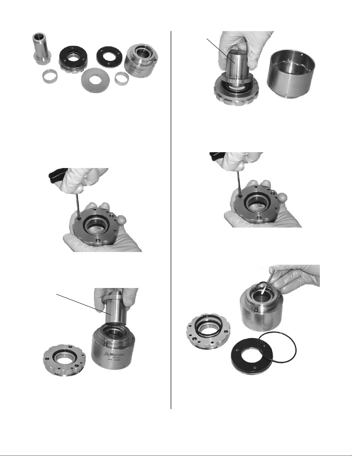
Figure 28
FIX-0001
Press Shaft out of unit. Separate remaining
components. Clean or replace all parts as required.
Use an alcohol based cleaning solvent to clean the
black driver magnets. Do not use anything abrasive
when wiping the black driver magnets. Use a Scotch
Brite deburr wheel to polish the hysteresis magnet.
See FIgure 28.
Figure 29
Using a 9/64” (M3) hex wrench, remove the socket
head cap screws. See Figure 29.
Figure 31
Using an arbor press and FIX-0001 install new
bearings in adjustable end cap and housing. See
Figure 31.
Figure 32
Using a 9/64” 3mm hex wrench, install magnet plate
assembly on adjustable end cap. See Figure 32.
FIX-0001
Figure 30
Using an arbor press and FIX-0001 push out
bearings in adjustable end cap and housing. See
Replace all seals and apply a light layer of grease on
seals. See Figure 33.
Figure 33
Figure 30.
8 Warner Electric • 800-825-9050 P-2018 • ZRC/ARC
Page 9

Figure 34
Install shaft into adjustable end cap magnet
assembly. Apply a light film of grease on magnet.
See Figure 34.
Figure 35
Install spacer on shaft on end cap. See Figure 35.
Figure 38
Install magnet plate in housing by holding the
magnet inside the housing body, lining up any three
holes, and tightening the three button head torx
screws using a T-15 security torx bit. See Figure 38.
Apply Grease
Figure 39
Apply a light film of grease on magnet. See Figure
39.
Figure 36
Install Hysteresis magnet. See Figure 36.
Figure 40
Torque
Settings
Torque
Index Mark
With torque settings on the housing and torque
index mark on end cap facing you, place housing on
end cap. Use caution as magnets will attract to each
Figure 37
Install second spacer. See Figure 37.
Warner Electric • 800-825-9050 P-2018 • ZRC/ARC 9
other. Tap in place with soft hammer if necessary.
See Figure 40.
Page 10
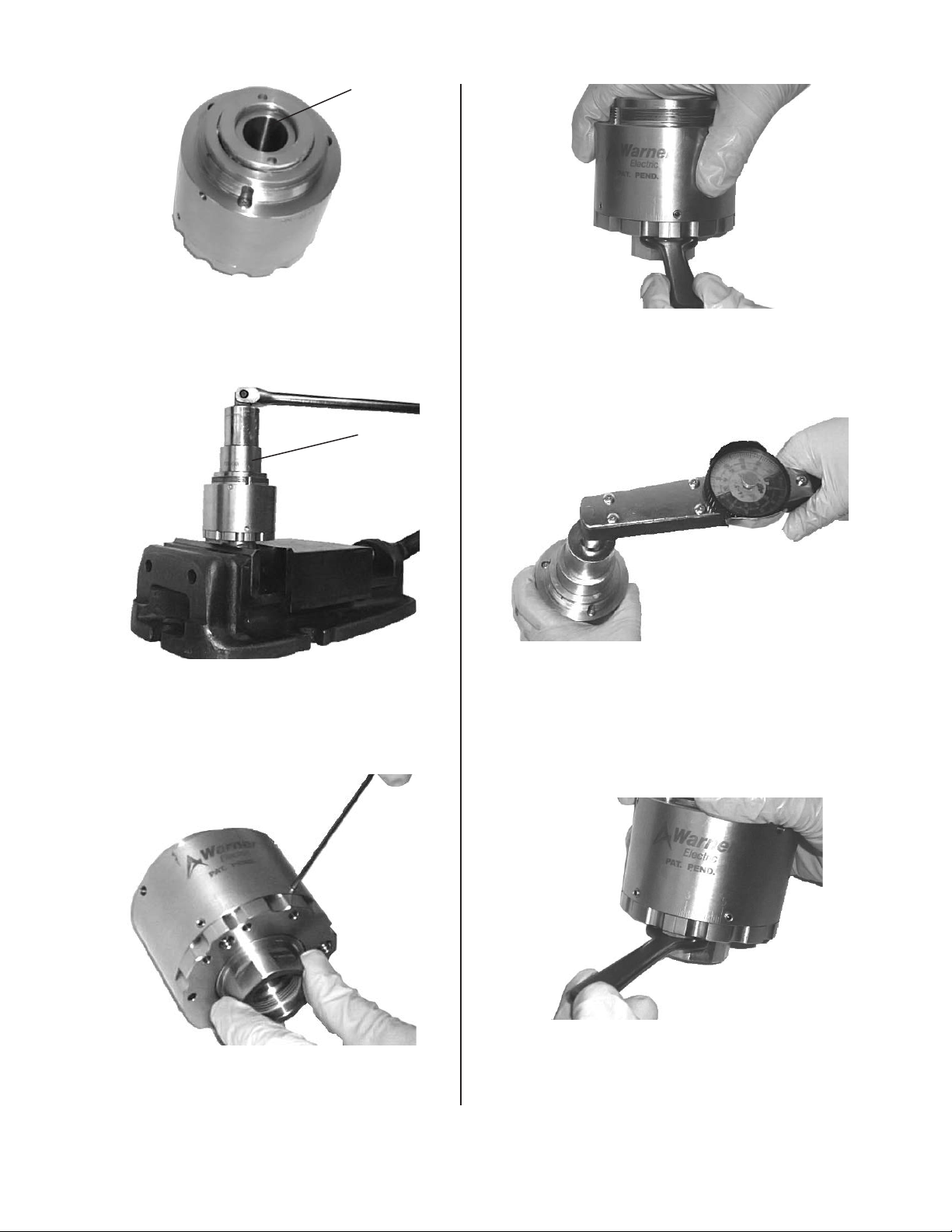
Figure 41
Apply Blue
Loctite
Apply blue loctite on ring nut. See Figure 41.
FIX-0004
Figure 42
Place chuck output shaft in vice, clamping on flats.
Using a socket, FIX-0004, and a breaker bar, torque
nut to 45 ft-lb (508 Ncm). See Figure 42.
Figure 44
Torque test the unit before re-installing upper
assembly and installing headset on machine. Using
face spanner wrench (YTL2-0002), set the torque at
setting 5. See Figure 44.
Figure 45
Using FIX-0007 or FIX-0010 and a torque wrench,
check to make sure the torque is smooth and
reaching the specified maximum torque. If torque
is not smooth or is very high, disassemble clutch
to look for mechanical rubbing or parts assembled
incorrectly. See Figure 45.
Figure 46
Figure 43
Install two set screws. See Figure 43.
Set torque to desired setting using face spanner
wrench (YTL2-0002) and tighten set screws. Tighten
set screws to 8-10 lb-in. Over tightening is not
necessary and will strip the screws or possibly
damage the housing body. See Figure 46.
10 Warner Electric • 800-825-9050 P-2018 • ZRC/ARC
Page 11
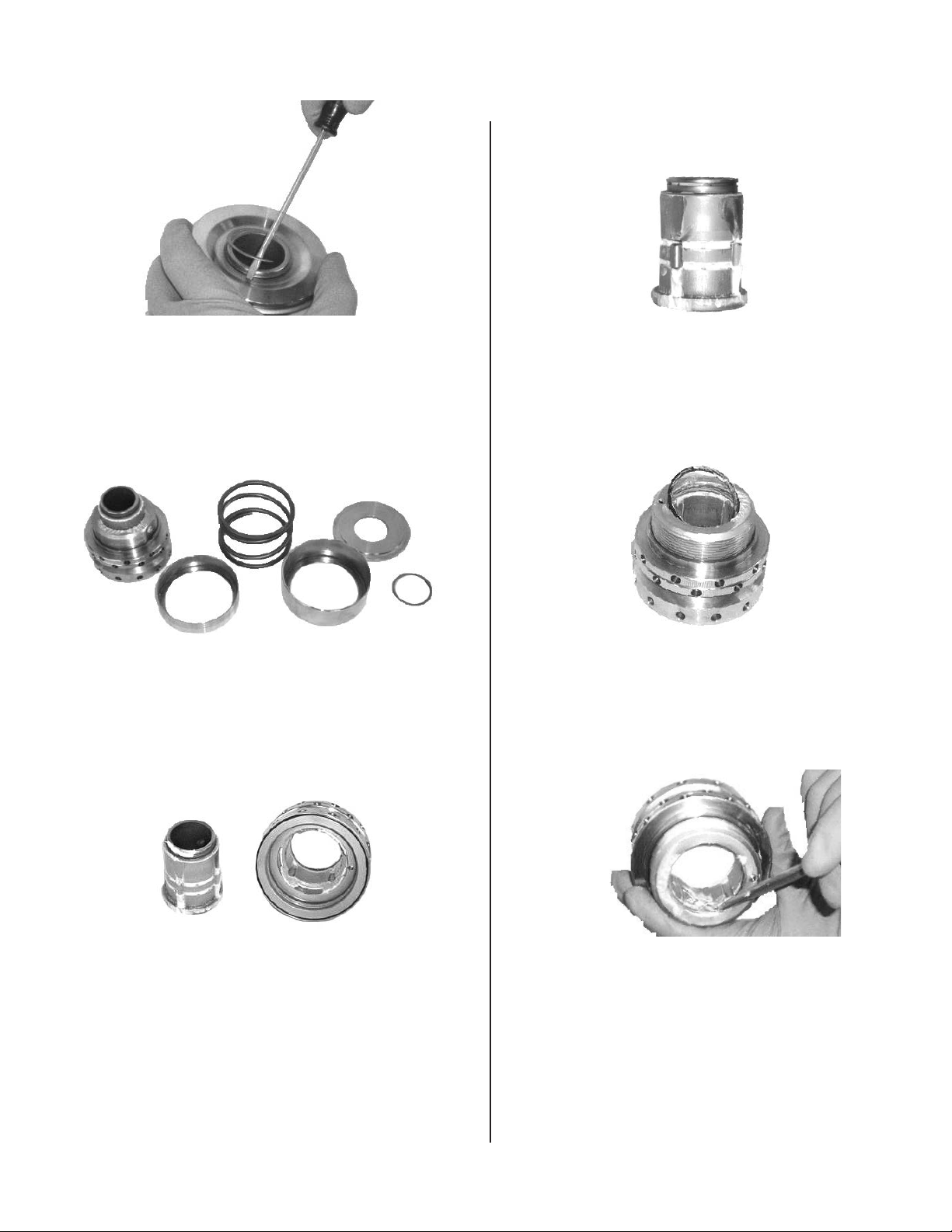
ARC Top Load Rebuild Procedure
Figure 47
Using a small standard screwdriver remove snap
ring. See Figure 52.
Figure 48
Remove spring plate, upper spring cover(if
applicable), spring, and lower spring cover (if
applicable) from top-load assembly. See Figure
53.
Figure 50
Install new pins, apply a thin layer of grease to
internal shaft and pins. See Figure 55.
Figure 51
Remove seal and replace. See Figure 56.
Figure 49
Remove internal shaft and inspect for wear,
replace as necessary. Clean all parts. See Figure
54.
Warner Electric • 800-825-9050 P-2018 • ZRC/ARC 11
Apply a thin layer of grease the seal and bore. See
Figure 57.
Figure 52
Page 12

Figure 53
Install shaft in top load assembly. Make sure all 4
pins stay engaged during insertion. See Figure 58.
Figure 56
Thread together the clutch and top-load assembly.
See Figure 61.
Figure 54
Set top-load on FIX-0002 so that the shaft does not
push in while compressing the spring. Install lower
spring cover (if applicable), spring, upper spring
cover (if applicable), and spring plate. See Figure 59.
Figure 55
Compress spring plate and install snap ring. Make
sure that the snap ring seats fully into groove. See
Figure 60.
Figure 57
Tighten using spanner wrenches (YTL3-0009) and a
soft hammer. See Figure 62.
Figure 58
Install set screw with 1/8” 3mm hex wrench; tighten.
Tighten set screws to 8-10 lb-in. Over tightening is
not necessary and will strip the screws or possibly
damage the housing body. See Figure 63.
12 Warner Electric • 800-825-9050 P-2018 • ZRC/ARC
Page 13

Rebuild Kits and Rebuild Exchange Programs
Warner Electric Capping Headsets
Magnetic Headset Rebuild Kits
End-users can purchase rebuild kits to rebuild the
magnetic headsets themselves. It is recommended that the end-user keep both bearing and magnetic kits on
hand in order to reduce maintenance downtime.
Factory Rebuild Program
End-users can ship their headsets back to Warner Electric for a full factory rebuild and certification. Upon
receipt, Warner Electric will rebuild and factory certify headsets. Typical turnaround for headsets is 1-2 weeks.
Expedited services are available upon request. Additional fees will apply. End-user will be invoiced for the
rebuilt headset when the rebuilt headset is shipped. The end-user is responsible for freight to and from factory.
Headset Exchange Program (TWO YEAR AGREEMENT):
Once end-users own Warner Electric headsets, they have the option of signing up for a Warner Electric
Headset Exchange Program for rebuilt headsets. In this case, end-users would receive rebuilt headsets from
Warner Electric at a predetermined time during the year in exchange for their used Warner Electric headsets.
End-user signs an agreement for the headset exchange program for 2 years. Pricing for the headset exchange
program will be paid once per year, on the date the agreement is signed and on the agreement anniversary
date. At the beginning of the agreement period, the end-user must specify the headset model, how many
heads are to be rebuilt, and what time(s) during the year rebuilt headsets are expected. Warner Electric will
ship rebuilt headsets to end-user at the predetermined date. Within two weeks from receipt of rebuilt headsets,
the end-user is required to return their used headsets. The end-user is responsible for freight to and from the
factory.
Headset Lease Exchange Program (3 YEAR AGREEMENT)
Warner Electric offers an option for end-users to receive factory rebuilt Warner Electric headsets at no initial
purchase fee if they sign up for a 3 year headset exchange program with Warner Electric. At the end of the 3
year agreement period, the end-user will own their Warner Electric headsets. End-user signs an agreement for
the headset exchange program for 3 years. Pricing for the headset exchange program will be paid once per
year, on the date the agreement is signed and on the agreement anniversary dates. At the beginning of the
agreement period, the end-user must specify the headset model, how many heads are to be rebuilt and what
time(s) during the year rebuilt headsets are expected. Upon receipt of initial payment, Warner Electric will ship
rebuilt headsets to the end-user. On the predetermined rebuild dates, Warner Electric will ship rebuilt headsets
to end-user. Within two weeks from receipt of rebuilt headsets, the end-user is required to return their used
headsets. At the end of the 3 year agreement period, the end-user will own their magnetic headsets. The enduser is responsible for all freight to and from the factory.
Warner Electric • 800-825-9050 P-2018 • ZRC/ARC 13
Page 14

On-site Service Support
Warner Electric Capping Headsets
On-site service support is available for installation of new Warner headsets, rebuild support of existing Warner
headsets, training, etc. Our factory-trained and certified service department with over 50 years combined
experience can help prevent costly delays and down time of your capping operation.
Precision Tork is the ONLY Service Group that is factory authorized to work on the
Warner Electric headsets.
Services Provided:
• Installation of new equipment
• Machine audits and troubleshooting
• Service and repair of filling and capping equipment
• Consulting: New Installations-existing issues for filling and capping
• Develop new design for efficient production
• Assist with planning of preventative maintenance programs
• Operator and mechanical training
• Highly qualified trained field engineers ready to work on the following bottling equipment:
• Alcoa • Zalkin • Fowler • AROL
Precision Tork Service Benets:
• We manufacture the headsets!
• Most up-to-date designs available only through Precision Tork.
• Our service technicians are trained to rebuild your headsets to their existing revision level OR upgrade
them to the latest technology.
• Component parts and rebuild kits on hand so you do not incur downtime.
• Coming soon…secure website for headset information and parts ordering with a credit card.
To schedule a certied Warner Service Technician contact Melissa Bottke at
1-888-350-1891
14 Warner Electric • 800-825-9050 P-2018 • ZRC/ARC
Page 15

Materials Requirements
Anti-Seize Compound
• Apply to spindle at time of headset installation Cleaning Solution
Cleaning Solution
• Alcohol based cleaning solvent used to wipe and clean parts during rebuild.
Grease
• Citgo Clarion Food Grade Grease, HTEP NLGI No. 2 Grade used to lubricate headset.
Loctite
• Blue Removable - 242 threadlocker used to secure components within the headset.
Epoxy
• Five minute epoxy – Amber, Devcon dev-pak adhesive 14270 used to fill counter-bores in the magnet
plate.
Information for Ordering Spare Parts
It is important to stock spare parts on hand to avoid unnecessary downtime. Warner recommends that you
stock at least two spare headsets per machine and a few bearing and magnet rebuild kits so that you have the
necessary parts on hand if you need them.
How to order spare parts – required information:
1. Purchase Order Number.
2. Warner headset model number/part number OR serial number (only on models manufactured July 2007
and later).
3. Warner Component or Kit Part Number.
4. Preferred distributor to order from. All orders will be routed through local distribution. Pricing and lead time
can be quoted by calling the Manufacturing Facility at (888) 350-1891.
Warner Electric • 800-825-9050 P-2018 • ZRC/ARC 15
Page 16

NOTES
16 Warner Electric • 800-825-9050 P-2018 • ZRC/ARC
Page 17

NOTES
Warner Electric • 800-825-9050 P-2018 • ZRC/ARC 17
Page 18

Warranty
Warner Electric LLC warrants that it will repair or replace (whichever it deems advisable) any product
manufactured and sold by it which proves to be defective in material or workmanship within a period of one (1)
year from the date of original purchase for consumer, commercial or industrial use.
This warranty extends only to the original purchaser and is not transferable or assignable without Warner Electric
LLC’s prior consent.
Warranty service can be obtained in the U.S.A. by returning any defective product, transportation charges
prepaid, to the appropriate Warner Electric LLC factory. Additional warranty information may be obtained by
writing the Customer Satisfaction Department, Warner Electric LLC, 449 Gardner Street, South Beloit, Illinois
61080, or by calling 815-389-3771.
A purchase receipt or other proof of original purchase will be required before warranty service is rendered. If
found defective under the terms of this warranty, repair or replacement will be made, without charge, together
with a refund for transportation costs. If found not to be defective, you will be notified and, with your consent, the
item will be repaired or replaced and returned to you at your expense.
This warranty covers normal use and does not cover damage or defect which results from alteration, accident,
neglect, or improper installation, operation, or maintenance.
Some states do not allow limitation on how long an implied warranty lasts, so the above limitation may not apply
to you.
Warner Electric LLC’s obligation under this warranty is limited to the repair or replacement of the defective
product and in no event shall Warner Electric LLC be liable for consequential, indirect, or incidental damages of
any kind incurred by reason of the manufacture, sale or use of any defective product. Warner Electric LLC neither
assumes nor authorizes any other person to give any other warranty or to assume any other obligation or liability
on its behalf.
WITH RESPECT TO CONSUMER USE OF THE PRODUCT, ANY IMPLIED WARRANTIES WHICH THE
CONSUMER MAY HAVE ARE LIMITED IN DURATION TO ONE YEAR FROM THE DATE OF ORIGINAL
CONSUMER PURCHASE. WITH RESPECT TO COMMERCIAL AND INDUSTRIAL USES OF THE PRODUCT,
THE FOREGOING WARRANTY IS IN LIEU OF AND EXCLUDES ALL OTHER WARRANTIES, WHETHER
EXPRESSED OR IMPLIED BY OPERATION OF LAW OR OTHERWISE, INCLUDING, BUT NOT LIMITED TO,
ANY IMPLIED WARRANTIES OF MERCHANTABILITY OR FITNESS.
Some states do not allow the exclusion or limitation of incidental or consequential damages, so the above
limitation or exclusion may not apply to you. This warranty gives you specific legal rights and you may also have
other rights which vary from state to state.
Changes in Dimensions and Specications
All dimensions and specifications shown in Warner Electric catalogs are subject to change without notice.
Weights do not include weight of boxing for shipment. Certified prints will be furnished without charge on request
to Warner Electric.
www.warnerelectric.com
31 Industrial Park Road
New Hartford, CT 06057
800-389-3771
Fax: 815-389-2582
P-2018-WE 3/14 Printed in USA
An Altra Industrial Motion Company
www.altramotion.com
 Loading...