

Page 1
P-2097-WE-A4
Tension Control System
XCTRL & XCTRL-2DRV
Installation and Operation Manual
Page 2

I. INTRODUCTION ...................................................................................................................................................................... 4
II. GENERAL INFORMATION ....................................................................................................................................................... 4
III. XCTRL BLOCK DIAGRAM ...................................................................................................................................................... 5
IV. HARDWARE PIN OUT ............................................................................................................................................................. 6
V. XCTRL- 2DRV ........................................................................................................................................................................... 7
VI. SYSTEM WIRING AND SETTING ............................................................................................................................................7
1. TYPICAL WIRING ................................................................................................................................................................ 7
2. OPERATION PRINCIPLE ...................................................................................................................................................... 7
3. DANCER ARM WIRING ........................................................................................................................................................ 8
4. LOAD CELL WIRING ............................................................................................................................................................ 8
5. POWER SUPPLY WIRING ....................................................................................................................................................9
6. WIRING WITH AN X2DRV .....................................................................................................................................................9
7. (OPTIONAL) AUXILIARY ANALOG SENSOR WIRING .......................................................................................................... 9
8. (OPTIONAL) MANUAL CALIBRATION .................................................................................................................................. 10
9. (OPTIONAL) TOUCH SCREEN INSTALLATION AND SETTING ............................................................................................ 11
A. WIRING THE XPRO INTERFACE TO THE XCTRL ...........................................................................................................11
VII. SOFTWARE INSTALLATION & SETTING ................................................................................................................................12
1. SOFTWARE DOWNLOADING ..............................................................................................................................................12
2. SOFTWARE INSTALLATION ................................................................................................................................................. 12
3. COMPUTER WIRING ............................................................................................................................................................ 12
VIII. XCTRL CONFIGURATION ....................................................................................................................................................... 13
1. XCTRL CONFIGURATOR LANGUAGE SELECTION ............................................................................................................ 13
2. PARTITION SETTING ............................................................................................................................................................ 13
• READ/WRITE PARTITION
• IMPORT/EXPORT PARTITION
• FACTORY DEFAULT
• SD CARD
........................................................................................................................................................................... 17
.................................................................................................................................................. 14
........................................................................................................................................... 15
.......................................................................................................................................................... 16
3. INPUT SELECTION AND SETTING ...................................................................................................................................... 18
• CELLS / DANCER INPUT
• CALIBRATION
.................................................................................................................................................................... 18
• RANGE DEFINITION
.................................................................................................................................................. 18
.......................................................................................................................................................... 19
4. PID SETTING ........................................................................................................................................................................ 20
• SELECT THE INPUT
• SET UP THE SETPOINT
• ENTER THE GAINS
• COMPENSATION
• STOP INTEGRAL (STPINT)
.......................................................................................................................................................... 20
.................................................................................................................................................... 20
............................................................................................................................................................ 20
............................................................................................................................................................... 20
................................................................................................................................................ 21
5. SPLICE SELECTION AND HOLD OUT CONFIGURATION ................................................................................................... 22
• SPLICE SELECTION
• HOLD OUT / MAX OUT
.......................................................................................................................................................... 23
..................................................................................................................................................... 24
6. INPUT/OUTPUT CONFIGURATION ...................................................................................................................................... 25
• DIGITAL INPUT SETTINGS
• SYNC INPUT ACTIVATION
• DIGITAL OUTPUT (ERRS1, ERRS2) SETTINGS
• THE ANALOG OUTPUT (OUT1, OUT2) SETTINGS
................................................................................................................................................ 25
................................................................................................................................................ 26
................................................................................................................ 26
........................................................................................................... 26
2 Warner Electric • +33 (0) 2 41 21 24 24
P-2097-WE-A4
Page 3

7. AUXILIARY SENSOR SETTING (ANA INPUT) .......................................................................................................................26
• AUXILIARY ANALOG INPUT TYPE
• AUXILIARY SENSOR CALIBRATION
.................................................................................................................................... 27
................................................................................................................................. 27
8. OPEN LOOP CONFIGURATION ........................................................................................................................................... 28
• LINEAR CURVE
• X FACTOR
................................................................................................................................................................. 28
.......................................................................................................................................................................... 28
9. DIAGNOSTIC TOOLS ........................................................................................................................................................... 29
• REAL TIME INFORMATION’ WINDOW
• INPUT/OUTPUT’ WINDOW
............................................................................................................................................... 31
.............................................................................................................................. 30
10. XCTRL FIRMWARE UPDATE ................................................................................................................................................32
IX. XCTRL FAMILY PART LIST .....................................................................................................................................................33
Warner Electric • +33 (0) 2 41 21 24 24 P-2097-WE-A4 3
Page 4
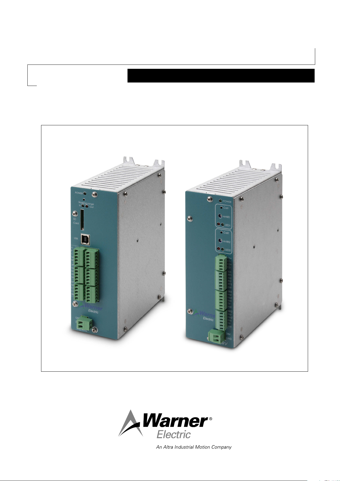
I. INTRODUCTION:
This control is a solid state electronic control that receives signal from a Dancer pivot point sensor or 2 Load cells
and transmits internally the appropriate signals to the brake power driver to regulate a stable tension.
It integrates 2 separate Digital PID controllers and 2 separate Open Loop control. Based on a double board architecture, it can integrate a Driver board to control our electromagnetic brakes range. In that particular case, all communication, Input/Output and power signal of the driver board will be made thru an internal connector.
All parameters could be saved to an integrated memory and to an SD Card, but can also be uploaded or downloaded
thanks to its external communication bus (USB).
In case of Load Cell application, when the setpoint needs to be modied, an optional handset is available.
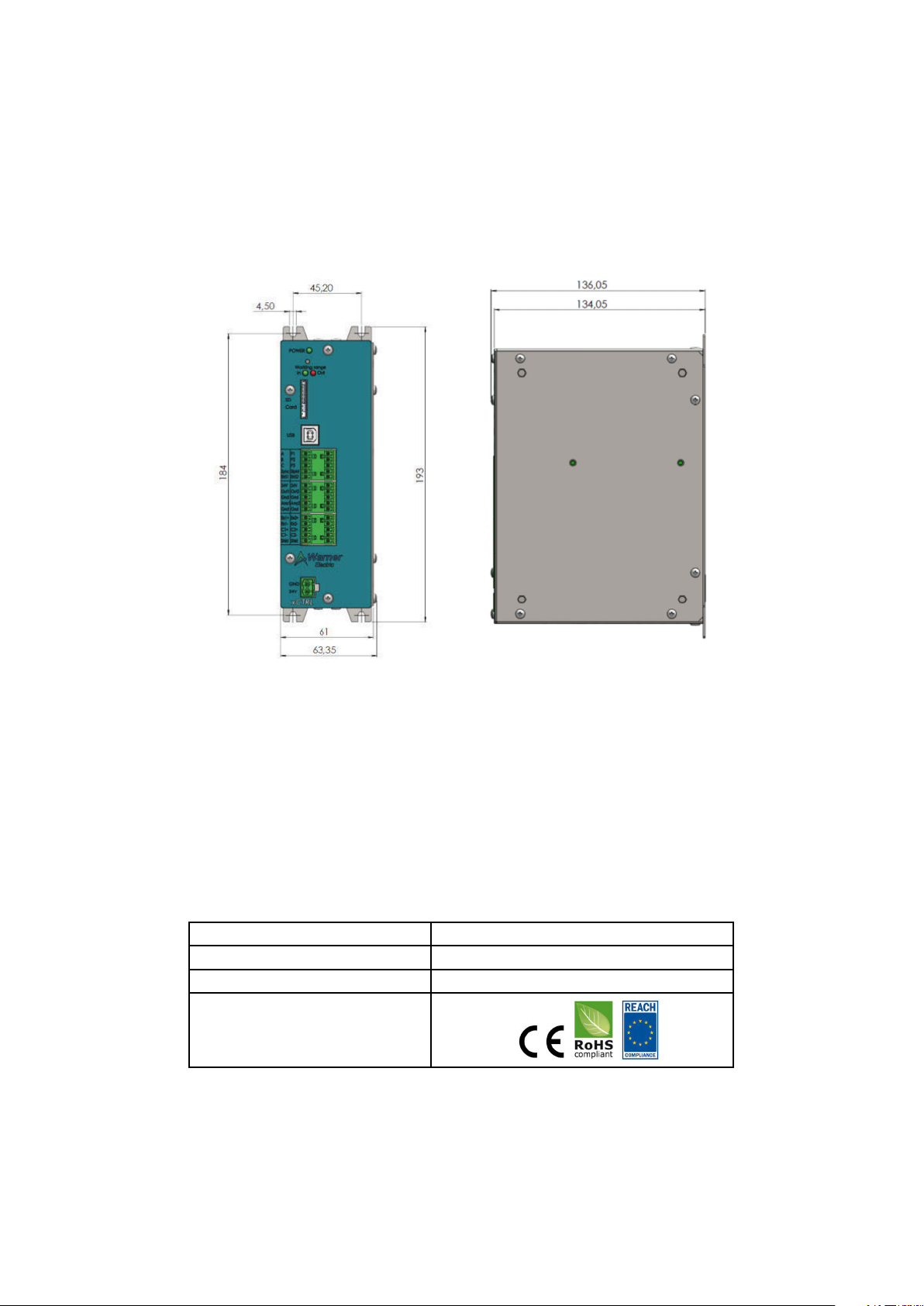
Figure 1: XCTRL Housing Dimensions
II. GENERAL INFORMATION
Control chassis should be kept clear of all areas where foreign material, dust, grease, or all might affect the operation of the control. Installation must be made in accordance with the instructions found in this manual. Failure to do
so may damage the Controller. Throughout this manual the PID board will be called the XCTRL board and the Driver
board will be called the X2DRV board.
Ratings
Main supply Voltage (V) 24V DC +/- 5%
Output 0-10V and/or 4-20mA
Operating T°C 0°C to 50°C no condensation
Compliance
4 Warner Electric • +33 (0) 2 41 21 24 24
P-2097-WE-A4
Page 5
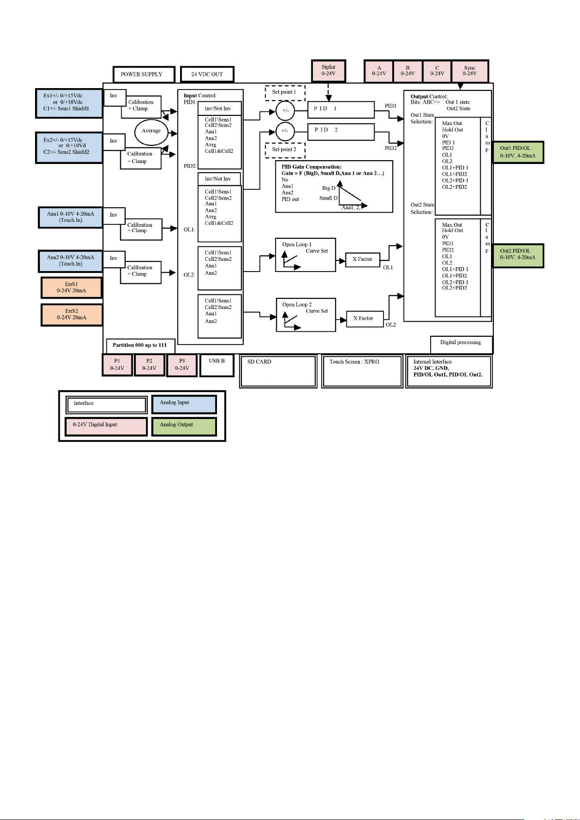
III. XCTRL Block Diagram
Figure 2: XCTRL Block Diagram
Warner Electric • +33 (0) 2 41 21 24 24 P-2097-WE-A4 5
Page 6

IV. Hardware Pin Out
1 SD Card External interface Parameters Savings. Possibility to save up to 8 partitions.
2 USB External interface
Use to setup the controller (Input/Output, PID, splice parameters) and to upload and download all parameters to a setup partition.
3 A Digital IN
4 B Digital IN
5 C Digital IN
6 Sync Digital IN
7 ErrS1 Digital Out
8 P1 Digital IN
9 P2 Digital IN
10 P3 Digital IN
11 Stplnt Digital IN
12 ErrS2 Digital Out
13 24V
14 Out1 Analog Output
15 Gnd Ground
16 Ana1 Analog Input
17 Gnd Ground
Power supply
OUT
Splice selection inputs. Depending on the A, B, C bit state, select a conguration of OUT1, OUT2, between a logical menu of 11 possibilities and select
PID1&2 compensation input
NPN, PNP input type Selectable.
Logical input which activate the changes of the A, B, C inputs. Depending on
logical setting, it could be activate on edge or on state.
NPN, PNP input type Selectable.
Error signal output to inform that Sensor1/Cell1 is out of range. Working range
can be programmed in %, Kg, Nm… 0-24VDC
Parameters Partition signal input. Depending on the P1, P2, P3 bit state, it
offers a selection to all parameters tables used to setup all Input/Output, PID
and Open loop controllers
NPN, PNP input type Selectable.
Stop or reset the integral calculation of the PID
NPN, PNP input type Selectable.
Error signal output to inform that Sensor2/Cell2 is out of range. Working range
can be programmed in %, Kg, Nm… 0-24VDC
Auxiliary 24VDC Power supply, 100mA
Analog Output of PID1 or Open Loop 1 out depending on ABC selection.
Selectable: 0/+10V DC or 4/20mA.
Auxiliary Sensor Input: usually used to compensate the PID Gain versus the
roll diameter
Selectable: 0/+10V DC or 4/20mA.
18 24V
19 Out2 Analog Output
20 Gnd Ground
21 Ana2 Analog Input
22 Gnd Ground
23 Ex1+ Power Out
24 Ex1- Power Out
25 C1+
26 C1-
27 Shld Shielding Load Cell or Sensor shielding
28 Ex2+ Power Out
29 Ex2- Power Out
30 C2+
31 C2-
32 Shld Shielding Load Cell or Sensor shielding
Power supply
OUT
Differential Analog
Input
Differential Analog
Input
24VDC Power supply, 100 mA
Analog Output of PID2 or OL2 out depending on ABC selection.
Selectable: 0/+10V DC or 4/20mA.
Auxiliary Sensor Input: usually used to compensate the PID Gain versus the
roll diameter
Selectable: 0/+10V DC or 4/20mA.
Sensor power supply & Load Cell excitation
Selectable 0-10Vdc or 0-15Vdc, 100mA
Load Cell and/or Dancer Arm sensor input
0-10Vdc, 0-40mVdc
Sensor power supply & Load Cell excitation
Selectable 0-10Vdc or 0-15Vdc, 100mA
Load Cell and/or Dancer Arm sensor input
0-10V DC, 0-40mVdc
This installation and Operating Manual has been arranged for the systematic installation and start-up of your
Tension Control System. Please check off each step before proceeding to the next step.
6 Warner Electric • +33 (0) 2 41 21 24 24
P-2097-WE-A4
Page 7
V. XCTRL- 2DRV
When working with the XCTRL-2DRV, no wiring between the XCTRL and the X2DRV control board are needed.
In fact, the power supply as well as the connections between the analog outputs (OUT1 & OUT2) of the XCTRL and
the analog inputs of the X2DRV (InBK1 & InBK2) control boards are internally made.
If more information is needed on the standalone X2DRV control, please refer to the ‘X2DRV Installation and Operation
Manual’
VI. System wiring and setting
WARNING: Contact with electrical voltages present in the controller covered in this manual can cause injury. To avoid
these consequences, make sure all power is off during installation.
These wiring precautions will help you properly install and wire a trouble-free system.
1. Use proper gauge wire for all pin:
- Data input: 0,5mm² (20 AWG) or 0,75mm² (18 AWG)
- Brakes wires: 0,75mm² (18 AWG) or 1mm² (17 AWG)
2. Shielded cable is recommended for all connections
3. Do not use this controller for purposes other than those intended. Such use could damage the controller
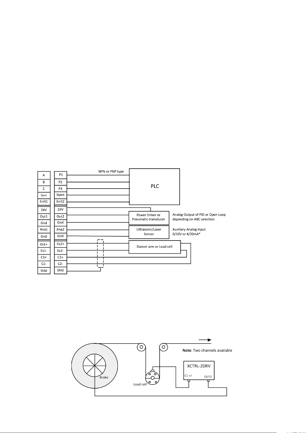
1. Typical Wiring
Figure 3: XCTRL Typical Wiring
2. Operation Principle
The closed Loop controls are usually made with using two types of sensors: the dancer arm and the load cell.
The XCTRL controller supports both. These two sensors provide a voltage signal proportional to the web tension. This signal is interpreted and the web tension is adjusted accordingly by braking thru one of the integrated PID controller.
Load Cell Applicaiton:
Figure 4: Load Cell Application
Warner Electric • +33 (0) 2 41 21 24 24 P-2097-WE-A4 7
Page 8
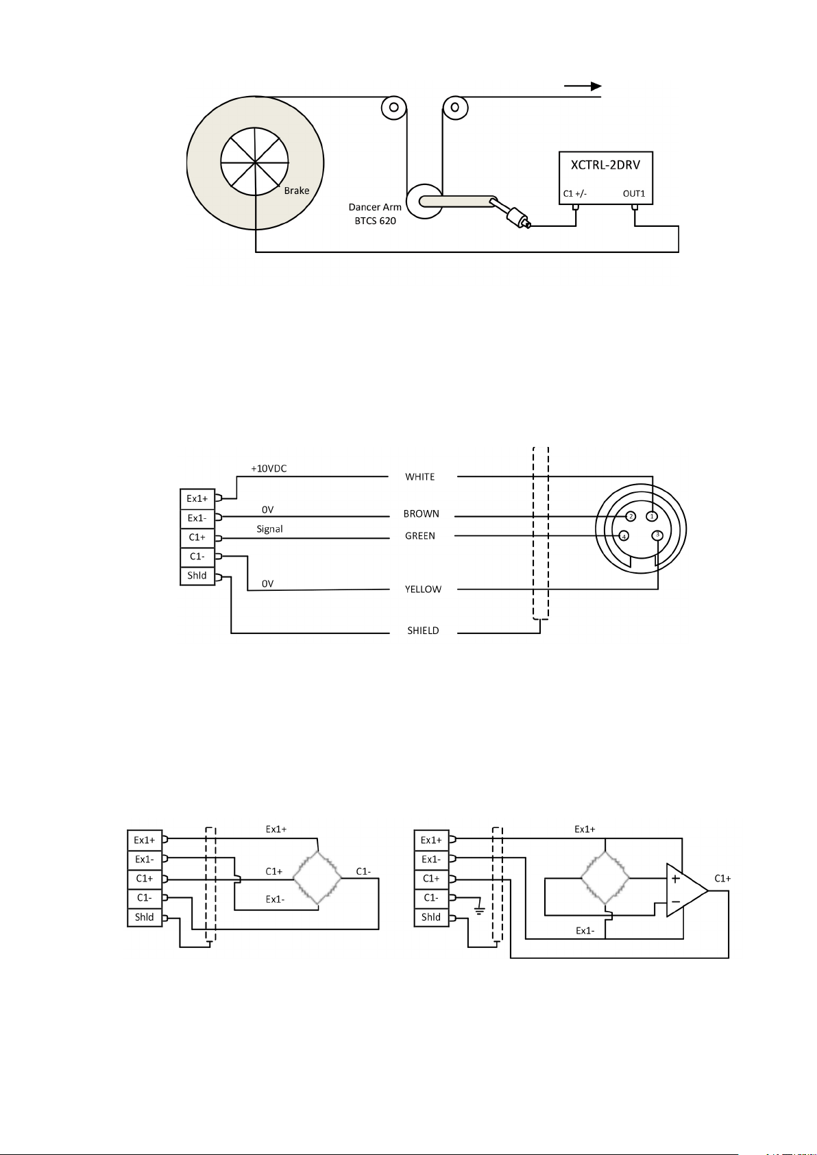
Dancer Arm Application:
Figure 5: Dancer Arm Application
3. Dancer Arm Wiring
Wire Dancer Arm BTCS605-E2 or BTCS 620 to the controller as describe below, use channel 1 or 2. For all
generalist wiring refer to gure 2 above. Please refer to the paragraph Input Selection and Setting to setup
the XCTRL accordingly.
Figure 6: Dancer Arm Wiring
4. Load Cell Wiring
Wire Load Cell (not amplied or amplied) to the controller as describe below, use channel 1 and/or 2. For all
generalist wiring refer to gure 2 above.
Figure 7: Not Amplified Load Cell Wiring Figure 8: Amplified Load Cell Wiring
Note: For all load cell wiring please refer to the corresponding Datasheet
8 Warner Electric • +33 (0) 2 41 21 24 24
P-2097-WE-A4
Page 9
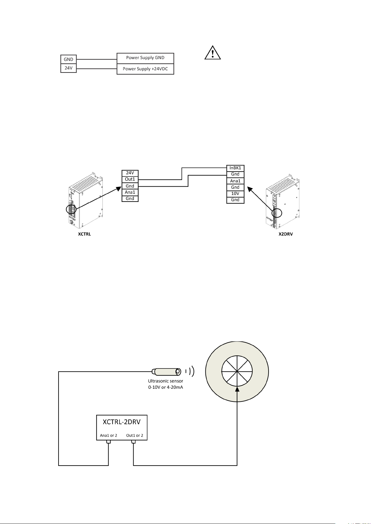
5. Power Supply Wiring
Wire 24VDC input power to pin 24V as shown below:
CAUTION: Improperly setting the
24VDC can damage the power
supply and/or the controller
Figure 9: Power supply wiring
6. Wiring with an X2DRV
If you don’t have an XCTRL-2DRV and you want to get a closed loop control, the XCTRL can be associated
with the X2DRV. For all detail about the driver refer to the X2DRV Installation & Operation manual. The XCTRL
output and the X2DRV Input are selectable (0-10V or 4-20mA). To wire the XCTRL with an X2DRV follow the
procedure below:
Note: 2 Channels available (Out1, Out2, InBK1, InBK2)
Figure 10: XCTRL & X2DRV wiring
Note: When the XCTRL is associated with an X2DRV (XCTRL-2DRV), power supply, input and communication are made by an internal connector. No connection extra connection between the controller and the driver
is needed.
7. (Optional) Auxiliary analog sensor wiring
Two auxiliary sensor inputs are available. They can both be programmed in 0-10Vdc or 4-20mA type Inputs.
They can also be used with the PID or the Open Loop Controllers input, refer to section 4.d and/or 4.h paragraph II/ Software Installation and Setting. The most popular use is to have them coupled to a roll diameter
sensor in order to compensate the PID Gain during unwinding
Figure 11: PID Gain Compensation in linear compensation mode
Figure 11: PID Gain Compensation in linear compensation mode
Warner Electric • +33 (0) 2 41 21 24 24 P-2097-WE-A4 9
Page 10
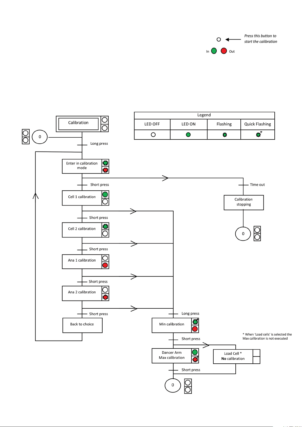
8. (Optional) Manual Calibration
The manual calibration of the XCTRL controller allows you to calibrate
the sensor Input (Cell1/Cell2) and the auxiliary sensor input (Ana1/Ana2)
without the XCTRL Congurator application. The calibrated values will
be then applied to the partition selected by P1, P2, P3 inputs.
Use the button above the green LED to start the calibration and follow
the procedure. A long press corresponds to 5s and a time out is equal
to 10s.
Procedure:
10 Warner Electric • +33 (0) 2 41 21 24 24
P-2097-WE-A4
Page 11
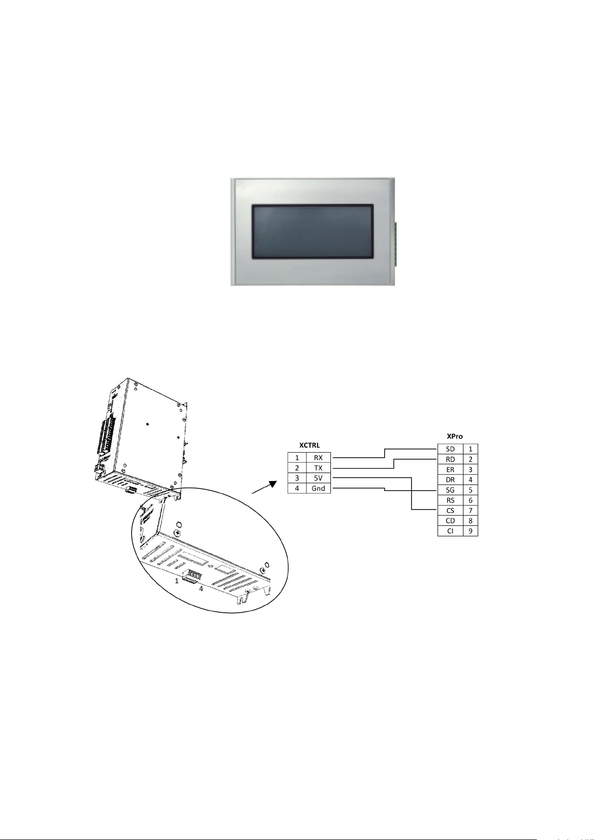
5. (Optional) Touch Screen Installation and Setting
The optional touch Screen (Xpro) allows you to modify the setpoint easily. It is generally necessary when
Load cells are used to change the tension while running.
It’s also offering to display some curves and values in real time.
If customer wants to use its own screen, a set of control code is described in the application note AN_
XPRO_SetOfCommand.pdf.
a. Wiring the XPro Interface to the XCTRL
Warner Electric • +33 (0) 2 41 21 24 24 P-2097-WE-A4 11
Page 12

VI. SOFTWARE INSTALLATION & SETTING
The “XCTRL congurator” is a user friendly software which allows you to easily set-up the XCTRL controller. It gives
you access to all parameters which could be modied and save into the integrated memory of the XCTRL. A Digital
oscilloscope is available to get an overview of the min parameters and the Inputs/Outputs variations.
1. Software downloading
This application is available on our Web site. Please visit our web site http://www.warnerelectric.com/ to
download it.
2. Software Installation
Unzip the folder name previously downloaded and open it. Double click on setup and follow the instructions.
Once the le is installed, the software will start running. If it’s not the case double click on the application
named XCTRL_Congurator.
3. Computer Wiring
To connect your computer to the XCTRL use an USB 2.0 cable type A to type B (not included) and wire it to
the USB ports as shown below:
Note: To get a link between the computer and the XCTRL, the XCTRL need to be supplied. For this refer to
section I/ System Wiring and Setting, item 3.
12 Warner Electric • +33 (0) 2 41 21 24 24
P-2097-WE-A4
Page 13

VII. XCTRL CONFIGURATION
1. XCTRL Congurator language Selection
Two languages are available: English and French. To select a language click on the main rolling menu and
select the desired language. By default French is selected.
2. Partition Setting
The set of parameters is called a partition. With recording and writing a partition you can easily check and
modify all parameters of the controller. With Saving or Opening a partition you are allowed to transfer all parameters from a computer or to a computer to backup or to email them for instance. The active partition can
also be selected by using the P1, P2, P3 inputs.
By default P1, P2, P3 are set to 0, giving then the partition 0 active when no wiring is made and thus independently of the NPN or PNP input mode selection.
Warner Electric • +33 (0) 2 41 21 24 24 P-2097-WE-A4 13
Page 14

• Read/Write Partition
This section allows you to Modify, to Check and to Save to the control all sets of parameters. You will nd on
the application a section named “Current partition” which represents the complete set of parameters (Cell/
Dancer parameters, PID, Splice, Input/output, Optional Inputs, …) of the partition selected by the number in
the box placed before.
- To read from XCTRL:
1) Select a number of partitions (P1P2P3).
2) Click on Read from XCtrl. The parameters of the XCTRL, saved into the internal memory, are then
loaded to the current partition, allowing you checking and modifying them.
- To write to XCTRL:
1) Select a number of partition (P1P2P3)
2) Click on Write to XCtrl. All parameter of the current partition are then loaded to the XCTRL memory.
14 Warner Electric • +33 (0) 2 41 21 24 24
P-2097-WE-A4
Page 15
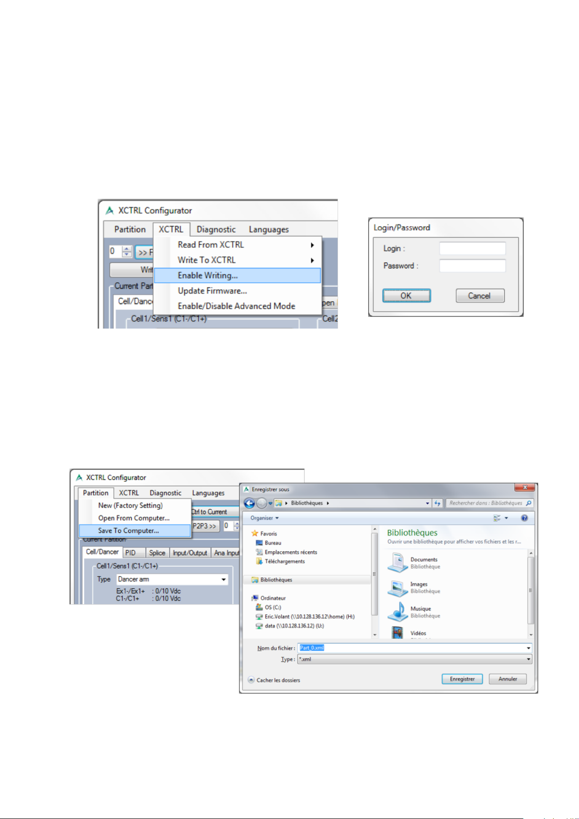
- How to enable the writing and the ‘Write Current to XCtrl Partition
P1P2P3’ button ?
To avoid any misuse, writing a partition is by default disabled. To enable it please follow the below
steps :
1) Click on ‘XCTRL’ in the main menu, then on ‘Enable Writing’.
2) A Login window pops up.
3) Please enter the following login and password: PARTITION, PARTITION. Both login and password
are case sensitive. They need to be entered in Uppercase.
4) Click on the ‘OK’ button. Both the ‘Write Current to XCtrl Partition P1P2P3’ and the ‘Write to
XCTRL’ buttons become enabled.
• Import/Export Partition
- To export a partition:
1) Choose the partition you want to save by selecting the correct number
2) Click on ‘Read P1P2P3 partition from XCTRL to Current’ button to load it in the Current partition.
3) Click on ‘Partition’ in the main menu, then on ‘Save to Computer’.
4) A le explorer opens to allow you to select the directory in which the partition is going to be saved.
5) Click on ‘Save’ button to save it.
Warner Electric • +33 (0) 2 41 21 24 24 P-2097-WE-A4 15
Page 16

- To import a partition:
1) In the main menu, Click on ‘Partition’, then on ‘Open from computer’
2) A le explorer opens to allow you to select the partition you want to import form you computer hard
drive or from another drive
3) The partition is then loaded in the Current partition
4) Select the partition number in which you want it to be saved.
5) Click on ‘Write Current to XCtrl Partition P1P2P3’ button to save it to the desired partition
• Factory Default
In case of misuse or of doubt in a setting, it’s very easy to recover the default setting set by default :
1) In the main menu, Click on ‘Partition’, then on ‘New (Factory setting)’
2) All default parameters are then loaded in the Current partition.
4) Select the partition number in which you want it to be saved.
5) Click on ‘Write Current to XCtrl Partition P1P2P3’ button to save it to the desired partition.
16 Warner Electric • +33 (0) 2 41 21 24 24
P-2097-WE-A4
Page 17

• SD Card
With an SD Card you can save all your partitions or write to the XCTRL from the SD Card. To write or save the
partitions follow the procedure below by using the button above the LED (In and Out).
The SD Card is not supplied with the XCTRL.
When reading from the SD Card, if only 1 partition has been saved on it, this one needs to have the number 0
and so named ‘PART_0.XML’. After having copied this rst partition, the application is searching for the next
one. If none is found, the application is getting into Error.
When writing, if the SD Card is full or secured, then the application is going into error.
Warner Electric • +33 (0) 2 41 21 24 24 P-2097-WE-A4 17
Page 18

1. Input Selection and Setting
• Cells / Dancer Input
In this tab you can select the active input and set-up it. Select your
input with the drop down menu. Depending of the Input type the
excitation and the input voltage will be changed
Two analog inputs are available. Each input can support either a
dancer arm (BTCS620 or BTCS 254-06/10) or a load cell. Both can
be amplied or not.
• Calibration
Once the input type selected, it’s necessary to teach the Input voltage span with a calibration. The calibration
differs from one type to another: In dancer arm type, Min and Max position needs to be taught when, in load
cell type Min position is only taught and Max position voltage needs to be entered manually.
- Dancer arm calibration:
Dancer arm: Min position: Voltage corresponding to the Max braking forces
Max position: Voltage corresponding to the Min braking forces
1) Put the Dancer Arm to Min position, press Min on the
software: Min is learnt automatically and displayed
2) Put the Dancer Arm to Max position, press Max on the
software: Max is learnt automatically and displayed
3) Click on ‘Write Current to XCtrl Partition P1P2P3’ button
to store these parameters into the integrated memory
18 Warner Electric • +33 (0) 2 41 21 24 24
P-2097-WE-A4
Page 19

- Load Cell (Amplied & Not Amplied) calibration:
In load cell Mode, the max voltage needs to be calculated depending of the load cell type, the
mechanical integration into the customer application and the max resultant load put on the cell. To
help you please ask the WARNER Electric the load cell calculation spreadsheet.
1) Put the Load Cell to Min, press Min on the software:
Min is learnt automatically and displayed
2) Set Max manually (according to the load cell)
3) ) Click on ‘Write Current to XCtrl Partition P1P2P3’ button
to Save these parameters
- Filtering & inverting the input.
In case of noisy applications, the vibrations can cause the PID control to ‘compensate’ the noise. To
avoid this behavior, it’s possible to add an extra ltering which is going to reduce the noise processed
by the controller.
To activate this lter :
1) Click on the ‘XCTRL’ button in the main menu and on ‘Enable/Disable Advanced mode’. Two
tick box are appearing below the calibration menu. The rst allow you to invert the input and the
second to lter it.
2) Tick the ‘Active lter’ box. A ‘Duration tab’ is appearing offering you the possibility to enter your
desired ltering time.
A ‘Invert Input’ button appears also, allowing you to invert the input if needed. In case of inversion,
the calibration of the input needs to be redone.
• Range Denition
To facilitate the value comprehension and the display, a logical range can be set-up, with selected its Unit, Min
and Max range Span and its Error threshold.
- Chose the working Unit (%, Kg, Nm …): any kinds of characters are
allowed. No conversion calculations are processed. This parameter is
only for display purpose to facilitate the comprehension of the input.
- Working Range: this is the “logical range” in which the controller will
process all its data. This has the advantage to facilitate the human
interfacing, with having both human and controller talks the same
“language”, actually the same unit. Set-up is according to your
application data.
- Error threshold: these Min and Max values are dening the error
threshold out of which the controller is emitting an Error signal. Once
the Sensor/load cell measured value is below or over these thresholds,
the XCTRL is triggering the Error Sense signals (ErrS1 or ErrS2). ErrS1
is linked to the Cell/Dancer 1 Input when ErrS2 is linked to the Cell/
Dancer 2 Input.
Warner Electric • +33 (0) 2 41 21 24 24 P-2097-WE-A4 19
Page 20

4. PID Setting
The PID tab is dening all PID controller parameters: PID Input selection, PID Automatic and linear
compensation, PID gains. The setpoint as well as the Stop Integral (StpInt) behavior can be also set-up in
this menu.
• Select the Input
With the drop down menu, it could be a dancer arm, one load
cell or two load cells. The input could be an auxiliary sensor
wired on Ana 1 or 2.
• Set up the SetPoint
Depending of the unit previously programmed the SetPoint’s unit
changes.
• Enter the Gains
With the drop down menu, you can directly enter the gain value
or increase it one by one. Gains are needed for the Proportional,
Integral and Derival correction
• Compensation
Depending of the application it’s sometimes useful to implement a PID Compensation. The compensation is
usually needed when the difference between the maximum and the minimum diameter of the roller exceed a 10
factor. Two compensation types are available: an automatic compensation and an external linear compensation.
- Automatic compensation: with the automatic compensation, no external sensor is needed. The PID
controller is adjusting automatically its gain between the Big and Small roller diameter gains entered.
20 Warner Electric • +33 (0) 2 41 21 24 24
P-2097-WE-A4
Page 21

- Linear compensation: to adjust its gain between the Big and the Small roller diameter, an external sensor
is needed. This sensor will measure the roller diameter and will need to be wired to the Ana1 or Ana2 Inputs.
These Inputs will need to be calibrated before being selected and used as compensation.
In linear compensation the external compensation input (Ana1 or Ana2) will be selected through the Splice
menu of “splice” tab. Due to the fact that in most of the applications the sensor is mechanically linked to the
roller, it’s obvious that the analog compensation input needs to be changed when splicing. Please refer to the
splice menu for selecting the correct Input versus the splice selection.
Set the compensation type with the drop down menu.
• Stop Integral (StpInt)
On machine’s stops, it’s necessary to stop the integral calculation of the PID controller. The main advantage
of doing so is a faster machine restart.
This function allows you to stop the integral calculation by two
different ways: reset or freeze. A reset will force the integral to
zero and a freeze will stop the integral to its current state.
The Stop Integral function is controlled by the StpInt Pin. As an
input, its activation can be selected as NPN or PNP type in the
Input/Output tab.
Warner Electric • +33 (0) 2 41 21 24 24 P-2097-WE-A4 21
Page 22

5. Splice Selection and Hold Out Conguration
This menu allows the user to set-up the roll’s
change/splice. Depending on the A, B, C, Sync
Inputs state, a PID controller’s output (an Open
Loop or a dened level) can be directed to different
outputs to control another driver channel, so another
brake/roll.
The splice activation is linked to the A B C Sync
input setup. Their activation can differ depending on
their type : NPN or PNP. Please refer to the Input/
Output Conguration tab for more information.
When the PID is running in Linear compensation mode,
a drop down menu is displayed to select the desired
compensation input (Ana1, or Ana2).
22 Warner Electric • +33 (0) 2 41 21 24 24
P-2097-WE-A4
Page 23

• Splice Selection
In this tab you can set up a conguration of OUT1, OUT2 between a logical menu of 11 possibilities. Please
follow the below procedure :
Warner Electric • +33 (0) 2 41 21 24 24 P-2097-WE-A4 23
Page 24

• Hold Out / Max out
Some more congurations are available for the “Max out” and the “hold out” levels. “Max Out” allows you to
set up the max voltage or current delivered by the Outputs.
The “hold out” feature is a procedure which is commonly used to stop a roll after splicing. This procedure
applies the “Max out” level during a certain time and switches automatically to the “hold out” level when this
time is over. Both “hold out level” and “Hold out delay” can be set with the application.
How to setup a Hold out? :
1) Enter “Max Out” Level
2) Enter “Hold Out” Level
3) Enter “Hold Out Delay”: Out1/2 will
be set at “Max Out” Level during this
delay
24 Warner Electric • +33 (0) 2 41 21 24 24
P-2097-WE-A4
Page 25

6. Input/Output Conguration
The “Input/Output” tab allows you to set-up the XCTRL Input/Outputs depending of your application
requirements. The XCTRL is able to handle two types of digital Input/Output : the NPN and the PNP type.
This hardware set-up denes the activation level of the splice Inputs (A,B,C,Sync), of the partition inputs (P1,
P2, P3), as well as the Digital (ErrS1, ErrS2) and Analog (Out1, Out2) outputs.
This conguration menu will affect the correct behavior of all Input/Output of the XCTRL.
So care must be taken with it!
Note: All states of the inputs and outputs are displayed in the Real Time window and Input/Output window.
Please refer to the Diagnostic tools tab for more information.
• Digital Input settings
Select in this tab the polarity type for A, B, C StpInt and P1, P2, P3 inputs. Two kind of polarity (1L) are
available: PNP (24V) and NPN (0V) :
- PNP: Logical active State : 1L = 24V. The low state 0L will be at 0V or GND.
- NPN: Logical active State : 1L = 0V. The low state 0L will be at 24V.
For all digital inputs, the polarity selection is common to all partitions. So any changes to a partition will be
automatically copied and pasted to all other partitions.
The “Sync Input” drop down menu allows the selection of the “Latch mode” of the ABC Inputs. When “Sync
Input” becomes active, the state of all ABC Inputs is transferred into the controller and processed.
Warner Electric • +33 (0) 2 41 21 24 24 P-2097-WE-A4 25
Page 26
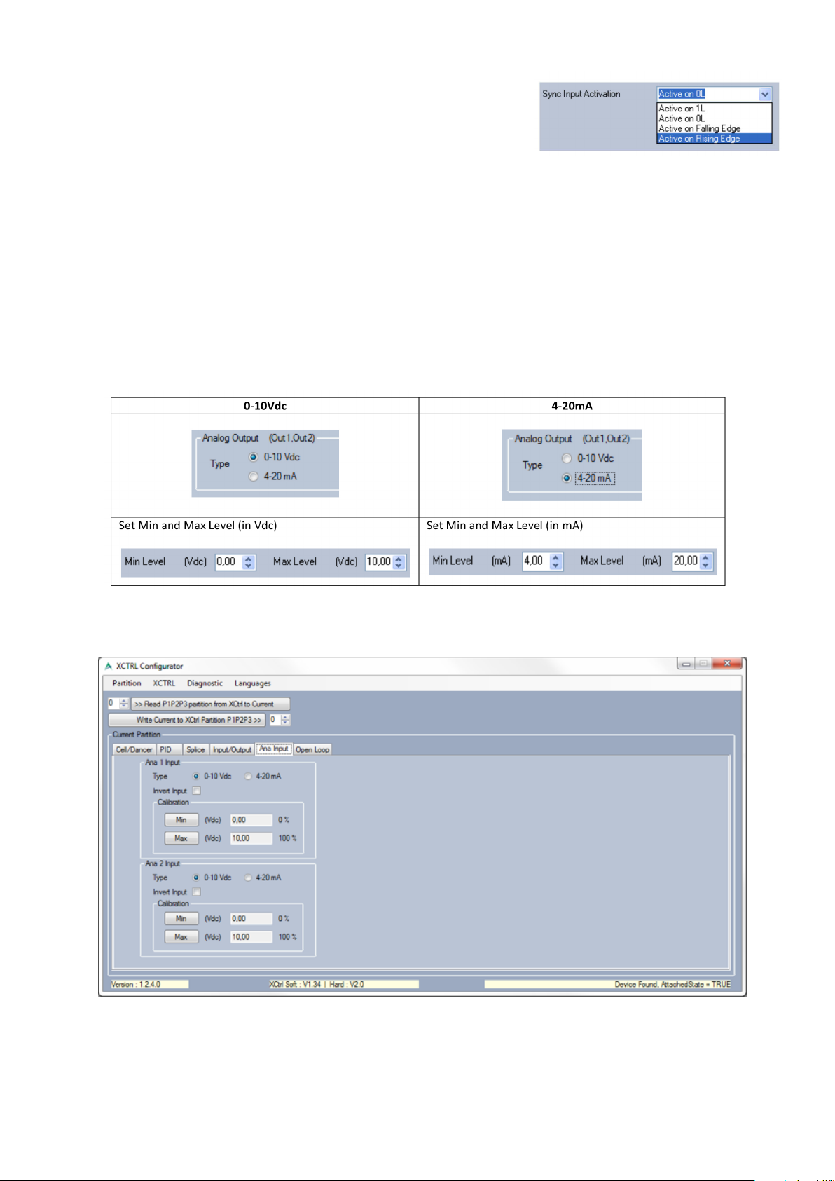
• Sync Input Activation
Active on 1L, active on 0L, active on falling edge or active on rising
edge. For each kind of activation a diagram is displayed on the
software to explain its working.
• Digital Output (ErrS1, ErrS2) settings
The ErrS1 and ErrS2 outputs are used to inform the external application (PLC, Computer,…) that the
corresponding Cell/Dancer Input is out of range. The “Error Range” is dened in the tab “Cell/Dancer”. The
polarity selection is like described above and can be chosen between NPN and PNP.
• The Analog output (Out1, Out2) settings
The Analog output (Out1, Out2) of the controller can be both controlled in voltage (0-10Vdc) or in current
(4-20mA), the selection is straight forward (below picture). On top of that, some absolute voltage/current
levels can be set. These levels will overdrive all logical levels which can be processed by the PID controller or
others.
7. Auxiliary Sensor Setting (Ana Input)
This tab allows you to setup both auxiliary inputs: Ana1 or Ana2. Both inputs can be set in voltage (0-10Vdc)
and in current (4-20mA).
26 Warner Electric • +33 (0) 2 41 21 24 24
P-2097-WE-A4
Page 27
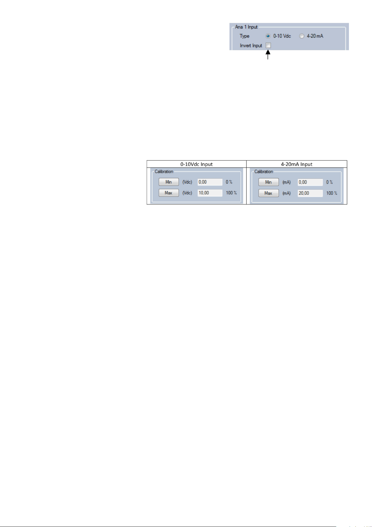
• Auxiliary Analog Input Type
Select between 0-10Vdc or 4-20mA
Note: Tick this box to invert the Analog Input
• Auxiliary sensor calibration
For a good behavior, it’s a mandatory to calibrate the voltage/current span of these inputs. Please follow the
below procedure to do so:
1) Put the Auxiliary sensor to Min, press Min on the software:
Min is learnt
2) Put the Auxiliary sensor to Max, press Max on the software:
Max is learnt
Warner Electric • +33 (0) 2 41 21 24 24 P-2097-WE-A4 27
Page 28

8. Open Loop Conguration
The XCTRL also integrates two open loop controls. The aim of these controls is to add a linear compensation
curve and/or a simple gain factor. The Input can be a load cell, a dancer arm or other analog sensors (e.g.
Ultrasonic Sensor).
• Select the Input
Note: For all information about control Pinout and
Wiring please refer to the Typical Wiring section.
• Two types of correction are available: Linear curve and X Factor. Both can also be
combined.
• Linear Curve
Out = A*In + B
In = Input voltage selected above
A = Curve Gain (could be negative)
B = Offset
Note: The Out level will not exceed 100% of
the span dened in the Input/Output tab.
• X Factor
Out = X Factor*In
In = Input voltage selected above or A*In+B
• How to Set Coefcients A & B and X Factor Value?
28 Warner Electric • +33 (0) 2 41 21 24 24
P-2097-WE-A4
Page 29
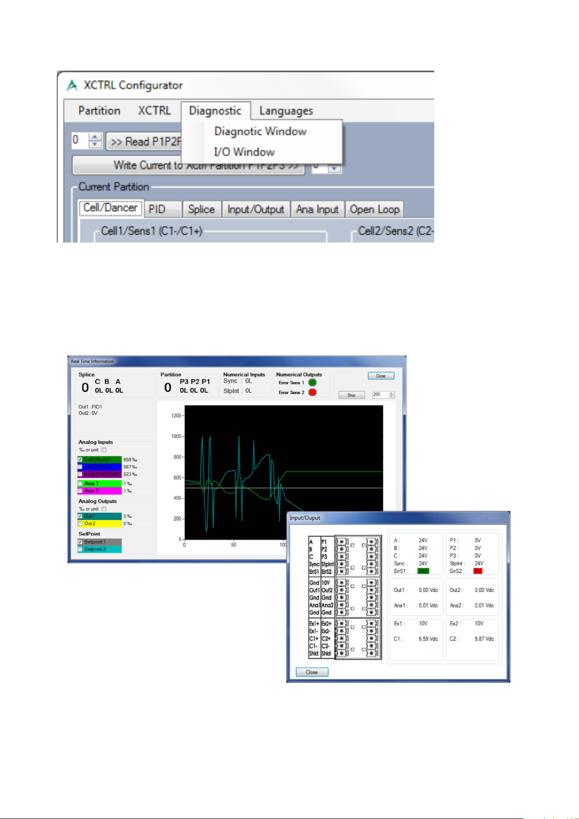
9. Diagnostic tools
This tab is giving access to 2 diagnostic windows. The rst one, named ‘Real time information’, gives an
overview of all inputs and outputs state, including the splice selection (A, B, C, Sync), the Stop integral
(StpInt), the partition selection (P1, P2, P3), the error state (ErrS1, ErrS2), and offers also a real time
oscilloscope allowing to see all inputs, outputs variations. The second, named ‘Input/output’ echoes back
the voltage or current applied to all pins.
Warner Electric • +33 (0) 2 41 21 24 24 P-2097-WE-A4 29
Page 30
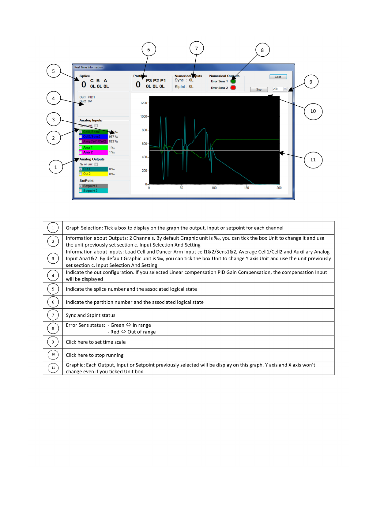
• ‘Real time information’ window
30 Warner Electric • +33 (0) 2 41 21 24 24
P-2097-WE-A4
Page 31
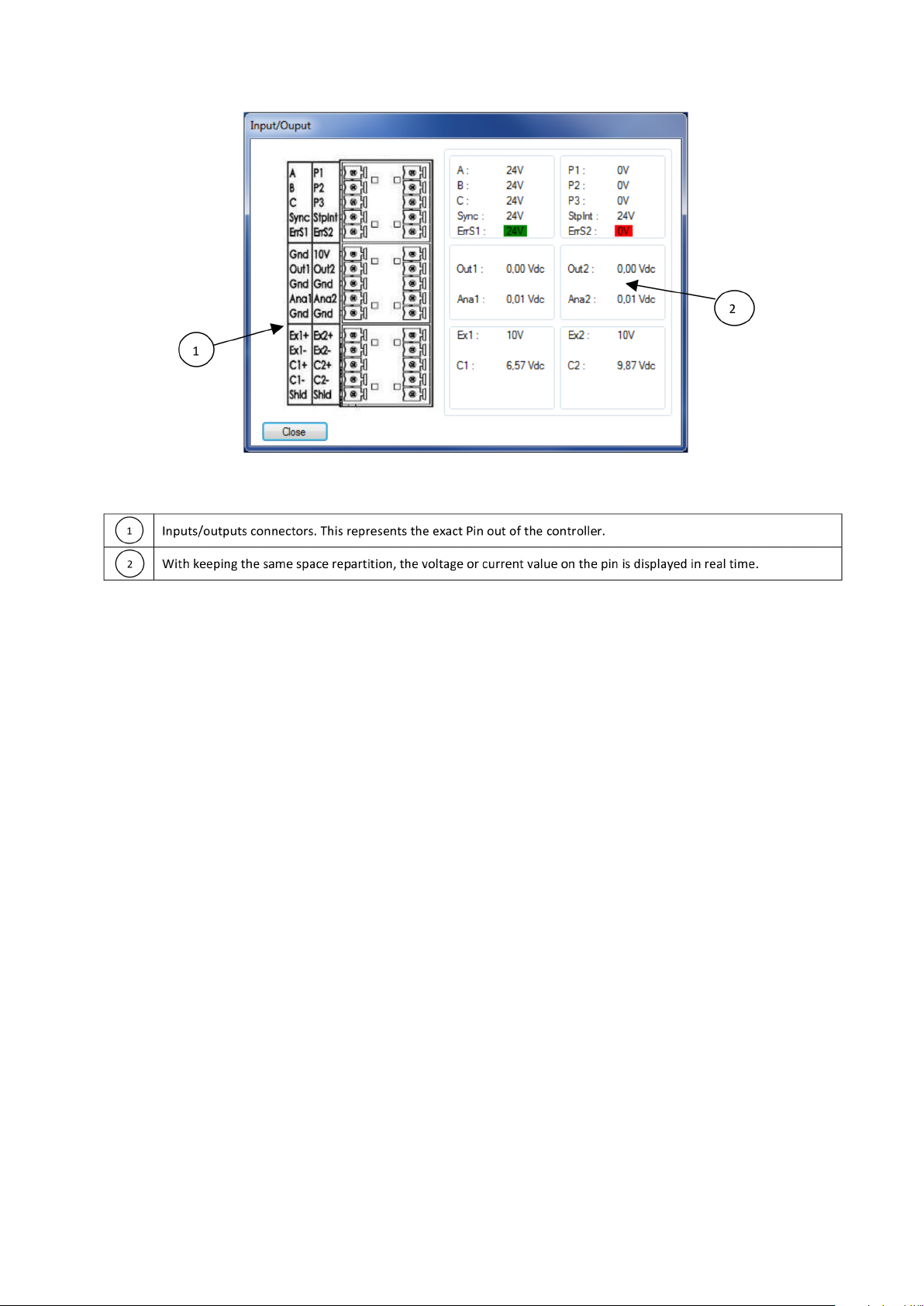
• Input/output’ window
Warner Electric • +33 (0) 2 41 21 24 24 P-2097-WE-A4 31
Page 32

10. XCTRL Firmware Update
When necessary , it’s possible to update the rmware of the XCtrl controller with using the XCtrl congurator
application. To do so, please follow the below steps:
1) Click on ‘XCTRL’ in the main menu, then on ‘Update Firmware’.
2) A Login window pops up.
3) Please enter the following login and password: (Please contact Warner to get it), (Please contact Warner
to get it). Both login and password are case sensitive. They need to be entered in Uppercase.
4) Click on the ‘OK’ button. A Bootloader agent is starting.
5) Click on the ‘Open Hex File’ push button and select the new rmware le
6) Click on ‘Program device’ button
7) Reset the XCtrl by clicking on ‘Reset Device’ button
32 Warner Electric • +33 (0) 2 41 21 24 24
P-2097-WE-A4
Page 33

VIII. XCTRL FAMILY PART LIST
When necessary, it’s possible to update the rmware of the XCtrl controller with using the XCtrl congurator
applicaiton.
Part Number Designation Description
BXCTRL XCTRL
BX2DRV X2DRV Double Channel 24Vdc Driver. 4A. 0-10VDC or 4-20mA inputs.
PID Control.
Double controller for Dancer arms and load cells application.
BXCTRL-2DRV XCTRL-2DRV PID Control + Double Driver.
BXPRO XPro Touch Screen Interface for XCTRL
BXUSBCable XUSBCable USB Cable - USB A, USB B
BXSDCard XSDCard SD Card + XCTRL Congurator
Not available XDIN Din rail xation
Warner Electric • +33 (0) 2 41 21 24 24 P-2097-WE-A4 33
Page 34

Warranty
Warner Electric LLC warrants that it will repair or replace (whichever it deems advisable) any product manufactured
and sold by it which proves to be defective in material or workmanship within a period of one (1) year from the date
of original purchase for consumer, commercial or industrial use.
This warranty extends only to the original purchaser and is not transferable or assignable without Warner Electric
LLC’s prior consent.
Warranty service can be obtained in the U.S.A. by returning any defective product, transportation charges prepaid,
to the appropriate Warner Electric LLC factory. Additional warranty information may be obtained by writing the
Customer Satisfaction Department, Warner Electric LLC, 449 Gardner Street, South Beloit, Illinois 61080, or by
calling 815-389-3771.
A purchase receipt or other proof of original purchase will be required before warranty service is rendered. If found
defective under the terms of this warranty, repair or replacement will be made, without charge, together with a refund
for transportation costs. If found not to be defective, you will be notied and, with your consent, the item will be
repaired or replaced and returned to you at your expense.
This warranty covers normal use and does not cover damage or defect which results from alteration, accident,
neglect, or improper installation, operation, or maintenance.
Some states do not allow limitation on how long an implied warranty lasts, so the above limitation may not apply to
you.
Warner Electric LLC’s obligation under this warranty is limited to the repair or replacement of the defective product
and in no event shall Warner Electric LLC be liable for consequential, indirect, or incidental damages of any kind
incurred by reason of the manufacture, sale or use of any defective product. Warner Electric LLC neither assumes
nor authorizes any other person to give any other warranty or to assume any other obligation or liability on its behalf.
WITH RESPECT TO CONSUMER USE OF THE PRODUCT, ANY IMPLIED WARRANTIES WHICH THE CONSUMER
MAY HAVE ARE LIMITED IN DURATION TO ONE YEAR FROM THE DATE OF ORIGINAL CONSUMER PURCHASE.
WITH RESPECT TO COMMERCIAL AND INDUSTRIAL USES OF THE PRODUCT, THE FOREGOING WARRANTY IS
IN LIEU OF AND EXCLUDES ALL OTHER WARRANTIES, WHETHER EXPRESSED OR IMPLIED BY OPERATION OF
LAW OR OTHERWISE, INCLUDING, BUT NOT LIMITED TO, ANY IMPLIED WARRANTIES OF MERCHANTABILITY
OR FITNESS.
Some states do not allow the exclusion or limitation of incidental or consequential damages, so the above limitation
or exclusion may not apply to you. This warranty gives you specic legal rights and you may also have other rights
which vary from state to state.
Changes in Dimensions and Specications
All dimensions and specications shown in Warner Electric catalogs are subject to change without notice. Weights
do not include weight of boxing for shipment. Certied prints will be furnished without charge on request to Warner
Electric.
Warner Electric
7 rue Champfleur, B.P. 20095, St Barthelemy d’Anjou - France
+33 (0)2 41 21 24 24 • Fax: +33 (0)2 41 21 24 70
www.warnerelectric.com
Printed in USAP-2097-WE-A4 • 10/13
 Loading...