

Page 1
P-2098-WE-A4
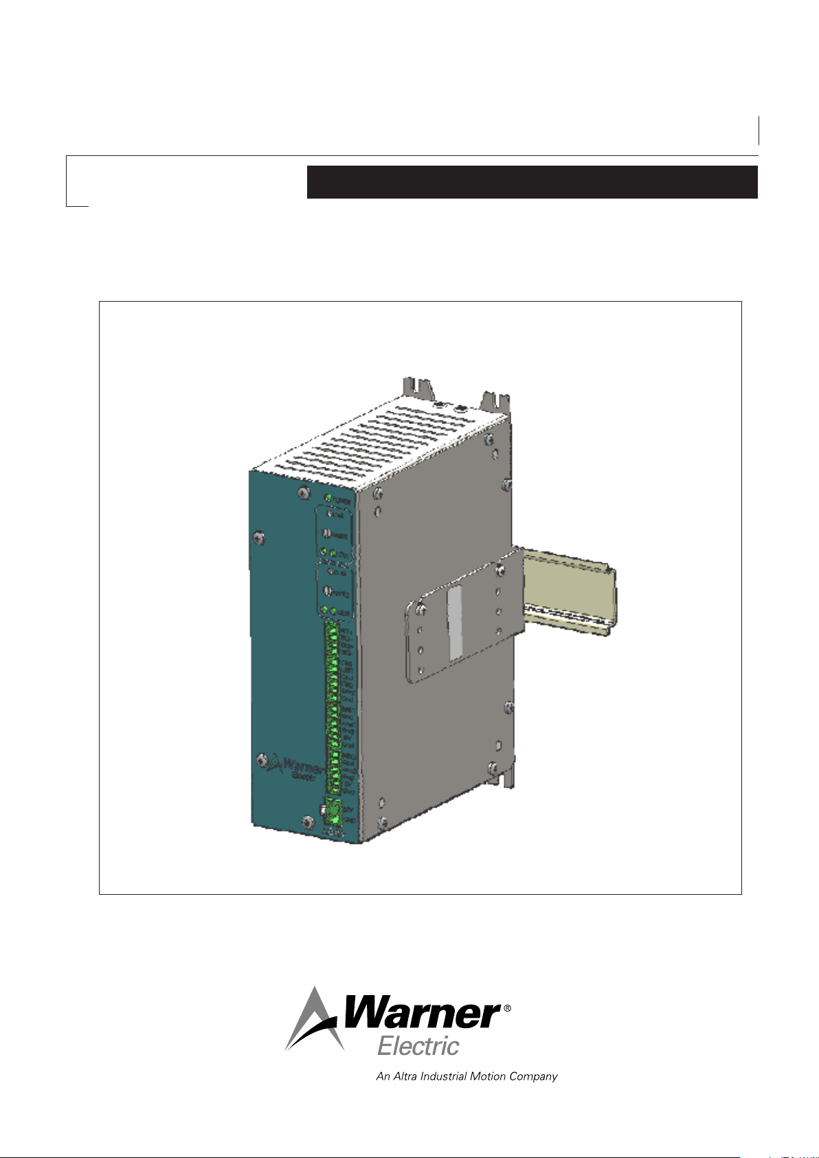
Tension Control System
X2DRV
Installation and Operation Manual
Page 2
INTRODUCTION:
The X2DRV is a solid state electronic control that will accept a variety of input signals and provides to the brake
an output current and voltage proportional to the input. This double channel driver can be operated by a remote
potentiometer, a voltage or a current loop input.
The X2DRV is a 24VDC double channel driver, 4Amps current capability.
When associated with an XCTRL, power supply, Input and (Communication) will be made by the internal connector.
This manual has been designed to cover the full range of installation, start-up and operation of your tension control
system.
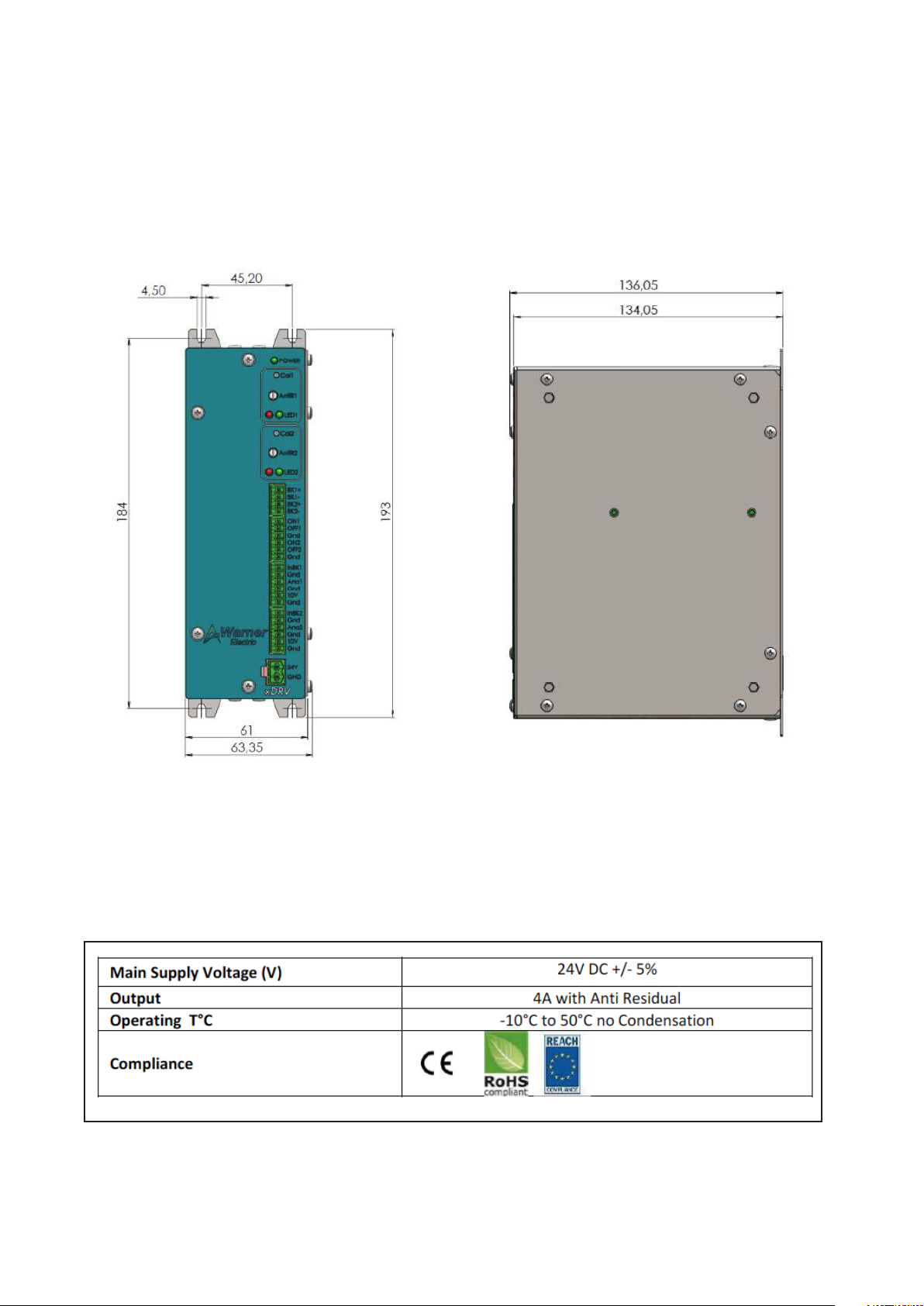
RATINGS:
2 Warner Electric • +33 (0) 2 41 21 24 24
Figure 1: X2DRV housing dimensions
P-2098-WE-A4
Page 3
GENERAL INFORMATION:
Control chassis should be kept clear of all areas where foreign material, dust, grease, or all might affect the operation
of the control. Installation must be made in accordance with the instructions found in this manual. Failure to do so
may damage the Driver.
This driver supports the following Warner brakes : TB’s, ATT’s, MPB’s, MPC’s. POB’s, POC’s and MTB’s brakes cannot be driven by this device.
INSTALLATION INSTRUCTIONS:
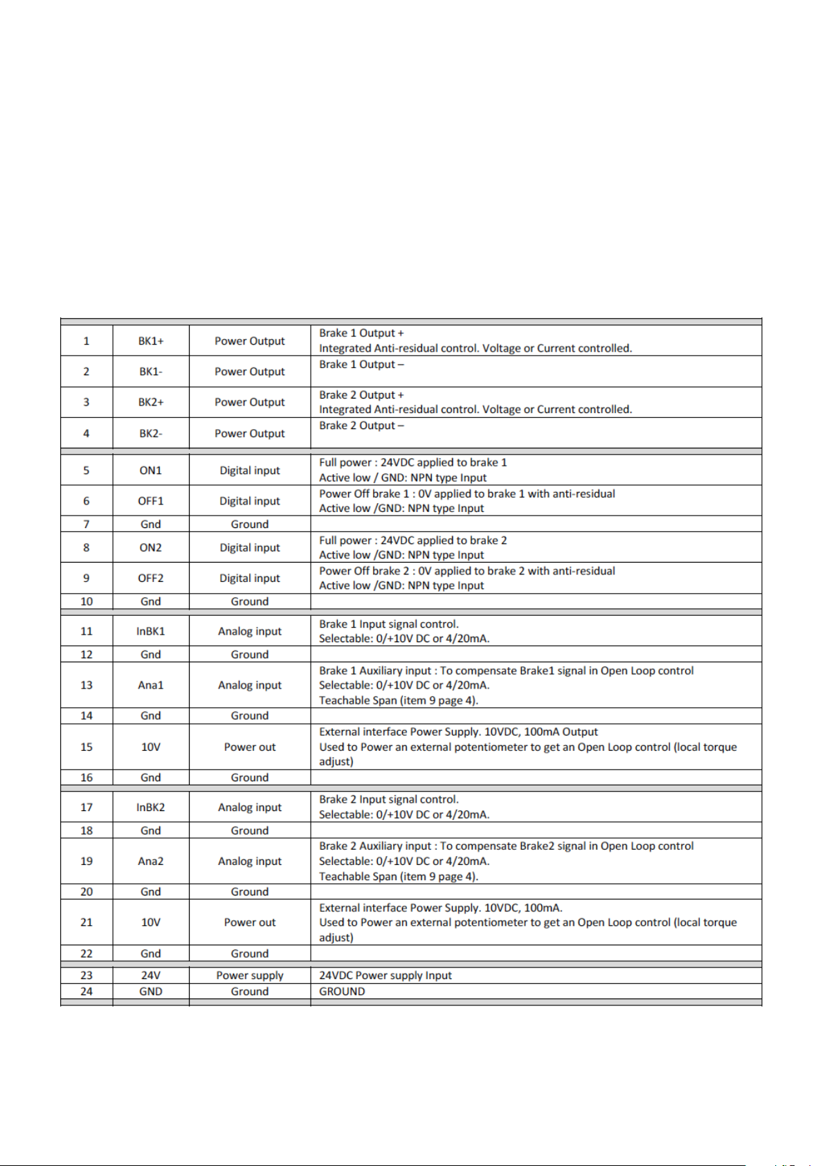
HARDWARE PIN OUT:
Warner Electric • +33 (0) 2 41 21 24 24 P-2098-WE-A4 3
Page 4

This installation and Operating Manual has been arranged for the systematic installation and start-up of your Tension
Control System. Please check off each step before proceeding to the next step.
SYSTEM WIRING AND SETTING:
WARNING: Contact with electrical voltages present in the driver covered in this manual can cause injury. To avoid these
consequences, make sure all power is off during installation.
These wiring precautions will help you properly install and wire a trouble-free system.
1. Use proper gauge wire for all pin :
• Data input : 0,5mm² (20AWG) or 0,75mm² (18AWG)
• Brakes wires : 0,75mm² (18AWG) or 1mm² (17AWG)
2. Shielded cable is recommended for all connections.
3. Do not use this driver for purposes other than those intended. Such use could damage the driver.
WIRING:
Figure 2: X2DRV wiring—one or two brakes
1. Wire 24V DC input power to pin 24V as shown in Figure 3.
CAUTION: Improperly setting the
24VDC can damage the power
supply and/or the driver
Figure 3: Power supply wiring
2. Connect wiring from brake magnets to Pin BK1 and/or BK2 of the X2DRV as shown in Figure 2.
3. Select the Input type with the red switches located along the bottom of the control:
4 Warner Electric • +33 (0) 2 41 21 24 24
P-2098-WE-A4
Page 5

4. Select the Output type with the red switches located along the bottom of the control:
5. Wire Controller or PLC (0-10V or 4-20mA Input) to pin InBK1 or InBK2 as shown in gure.
6. Set the Anti-residual with the white screw as shown in Figure 4 as described below:
a. Apply the brake at 0V or 4mA on InBK (1 or 2) or activate
the Brake-Off (OFF1 or OFF2).
b. Check the Brake armature oats away from the Brake
magnet with no sticking.
c. If the armature sticks to the magnet, set the
Anti-Residual (AntiR1 or AntiR2) as shown below until the
armature is free with no sticking.
Figure 4: Anti-residual calibration
d. Reapply the Brake at 10V or 20mA on InBK (1 or 2)
or by returning the Brake-Off (OFF1 or 2) Pin to its normal
position and activating the Brake-On input (ON1 or 2).
e. If Brake releases freely, make no further adjustments as the
Anti-Residual is now set.
Potentiometer for
Anti-residual setting
Anti-Residual adjustment Voltage Output versus anti-residual control
7. (Optional): Pins ON1, OFF1, ON2, OFF2 are NPN type Input:
•When ON (1 or 2) is set to Ground => 24V is applied on BK (1 or 2) output
•When OFF (1 or 2) is set to Ground => 0V with Anti-residual is applied on BK (1 or 2) output
8. (Optional): To get an Open Loop control use the external interface power supply (10V DC) as shown in
Figure 2 to supply a potentiometer or others as described in Figure 5.
Figure 5: Typical Open Loop application
with diameter compensation
Warner Electric • +33 (0) 2 41 21 24 24 P-2098-WE-A4 5
Page 6

9. Auxiliary Analog Sensor (Teachable Span)
In case of use an analog sensor or two, wire them to Pin Ana1 or Ana2 and teach their voltage or current span with
starting the calibration as describe below (for this use the button Cal as shown figure 6). If no calibration is done,
Ana1 or Ana2 are ignored. The Analog Input (Ana) compensates the Brake Input signal control (InBK) between
20-100%.
To Disable Ana1 or Ana2 compensation, please calibrate Ana1 or 2 without any connection (unplugged).
Auxillary Input Calibration: Ana1 & Ana2
Potentiometer for Anti-residual setting
State LED
Figure 6: Anti-residual setting and calibration
10. (Optional): The frequency adjustment changes the modulation frequency to eliminate brake “hum” or “howl”
when the brake is stationary. The frequency is factory set and normally requires no adjustments. Set the frequency as
described below with the red switches below the chassis:
11. Double check all wiring connections per Figure 2 and insure all terminals are tight.
NOTE: If an over-load occurs (current 4A or more) the Driver output will shut down and the red LED will be ON. To
reset the system, remove power to the Driver and turn it on again.
6 Warner Electric • +33 (0) 2 41 21 24 24
P-2098-WE-A4
Page 7

X2DRV BLOCK DIAGRAM:
Warner Electric • +33 (0) 2 41 21 24 24 P-2098-WE-A4 7
Page 8

Warranty
Warner Electric LLC warrants that it will repair or replace (whichever it deems advisable) any product manufactured
and sold by it which proves to be defective in material or workmanship within a period of one (1) year from the date
of original purchase for consumer, commercial or industrial use.
This warranty extends only to the original purchaser and is not transferable or assignable without Warner Electric
LLC’s prior consent.
Warranty service can be obtained in the U.S.A. by returning any defective product, transportation charges prepaid,
to the appropriate Warner Electric LLC factory. Additional warranty information may be obtained by writing the
Customer Satisfaction Department, Warner Electric LLC, 7 rue Champeur, B.P. 20095, St Barthelemy d’Anjou France, or by calling +33 (0)2 41 21 24 24.
A purchase receipt or other proof of original purchase will be required before warranty service is rendered. If found
defective under the terms of this warranty, repair or replacement will be made, without charge, together with a refund
for transportation costs. If found not to be defective, you will be notied and, with your consent, the item will be
repaired or replaced and returned to you at your expense.
This warranty covers normal use and does not cover damage or defect which results from alteration, accident,
neglect, or improper installation, operation, or maintenance.
Some states do not allow limitation on how long an implied warranty lasts, so the above limitation may not apply to
you.
Warner Electric LLC’s obligation under this warranty is limited to the repair or replacement of the defective product
and in no event shall Warner Electric LLC be liable for consequential, indirect, or incidental damages of any kind
incurred by reason of the manufacture, sale or use of any defective product. Warner Electric LLC neither assumes
nor authorizes any other person to give any other warranty or to assume any other obligation or liability on its behalf.
WITH RESPECT TO CONSUMER USE OF THE PRODUCT, ANY IMPLIED WARRANTIES WHICH THE CONSUMER
MAY HAVE ARE LIMITED IN DURATION TO ONE YEAR FROM THE DATE OF ORIGINAL CONSUMER PURCHASE.
WITH RESPECT TO COMMERCIAL AND INDUSTRIAL USES OF THE PRODUCT, THE FOREGOING WARRANTY IS
IN LIEU OF AND EXCLUDES ALL OTHER WARRANTIES, WHETHER EXPRESSED OR IMPLIED BY OPERATION OF
LAW OR OTHERWISE, INCLUDING, BUT NOT LIMITED TO, ANY IMPLIED WARRANTIES OF MERCHANTABILITY
OR FITNESS.
Some states do not allow the exclusion or limitation of incidental or consequential damages, so the above limitation
or exclusion may not apply to you. This warranty gives you specic legal rights and you may also have other rights
which vary from state to state.
Changes in Dimensions and Specications
All dimensions and specications shown in Warner Electric catalogs are subject to change without notice. Weights
do not include weight of boxing for shipment. Certied prints will be furnished without charge on request to Warner
Electric.
Warner Electric
7 rue Champfleur, B.P. 20095, St Barthelemy d’Anjou - France
+33 (0)2 41 21 24 24 • Fax: +33 (0)2 41 21 24 70
www.warnerelectric.com
Printed in USAP-2098-WE-A4 • 10/13
 Loading...