

Page 1
12
Wheel-Brakes
1
⁄4 x 51⁄2, 15 x 3, 161⁄2 x 5-6-7 (Std)
1
16 x 2
⁄2, 171⁄4 x 3-4-5
AA-110
819-0514
Installation & Operating Instructions
Page 2

Contents
Section l. Description And Operation . . . . . . . . . . . . . 4
Description and Operation. . . . . . . . . . . . . . . . . . . . 4
How to Break in Trailer Brakes . . . . . . . . . . . . . . . . 5
How to Apply Brakes . . . . . . . . . . . . . . . . . . . . . . . . 5
Section ll. Installation . . . . . . . . . . . . . . . . . . . . . . . . . . 6
Prepare for Installation . . . . . . . . . . . . . . . . . . . . . . . 6
Install and Check Drum . . . . . . . . . . . . . . . . . . . . . . 6
Install Flanges . . . . . . . . . . . . . . . . . . . . . . . . . . . . . 6
Install Brakes . . . . . . . . . . . . . . . . . . . . . . . . . . . . . . 8
Install Armature in Drum . . . . . . . . . . . . . . . . . . . . . 8
Check Armature Depression . . . . . . . . . . . . . . . . . . 9
Adjust Armature Depression . . . . . . . . . . . . . . . . . 11
Cleaning . . . . . . . . . . . . . . . . . . . . . . . . . . . . . . . . . 11
Electrical Connections . . . . . . . . . . . . . . . . . . . . . . 11
Section lll. Maintenance. . . . . . . . . . . . . . . . . . . . . . . 12
Check Current Available . . . . . . . . . . . . . . . . . . . . . . . 12
Table I. Magnet Current Rating . . . . . . . . . . . . . . . 13
Check Amperage at Each Brake . . . . . . . . . . . . . . 14
Check for Lining Wear . . . . . . . . . . . . . . . . . . . . . . 14
Table II. Lining Wear. . . . . . . . . . . . . . . . . . . . . . . . 14
Check for Loose Wheel Bearings . . . . . . . . . . . . . 15
Inspect Drums . . . . . . . . . . . . . . . . . . . . . . . . . . . . 15
Drum and Lining Clearance . . . . . . . . . . . . . . . . . . 16
Relining Brakes . . . . . . . . . . . . . . . . . . . . . . . . . . . 16
Table III. Drum Rebore and Brake
Reline Tolerances . . . . . . . . . . . . . . . . . . . . . . . . . . 17
Check Magnet and Armature. . . . . . . . . . . . . . . . . 17
Replacement of Magnets and Armatures . . . . . . . 18
Table IV. Magnet and Armature Wear . . . . . . . . . . 19
Testing Magnet. . . . . . . . . . . . . . . . . . . . . . . . . . . . 20
Replacing Magnet Leads . . . . . . . . . . . . . . . . . . . . 21
Warranty . . . . . . . . . . . . . . . . . . . . . . . . . . . . Back Page
Warner Electric • 800-825-9050 819-0514
2
Page 3

Brake Band
Magnet
Cam Lever
Trunnion
Armature
Drum
Spider
Brake Band
Dust Cover
Magnet
Cam Lever
Armature
Spider
Trunnion
Dust Cover
Brake Shoe
2-1/4 x 5-1/2 Brakes
Armature
Magnet
Cam Lever
Amature Adapter
Drum
Trunnion
Armature
Brake Band
Magnet
15 x 3 Brakes
Backing Plate
Drum
Trunnion
Cam Lever
16-1/2 x 5-6-7 Brakes
Warner Electric • 800-825-9050 819-0514
16 x 2-1/2 and 17-1/4 x 3-4-5 Brakes
3
Page 4

Failure to follow these instructions
may result in product damage, equipment damage,
and serious or fatal injury to personnel.
Section l
Description and Operation
The Warner Electric Brake is basically a mechanical
friction brake which uses a simple principle of
electricity for its actuation. The small amount of
electrical current required is obtained from the storage
battery and/or generator with which every towing
vehicle is equipped.
Unlike the ignition system of the engine, the Warner
Electric Brake does not require the use of high tension
current; therefore, no harmful shock is possible.
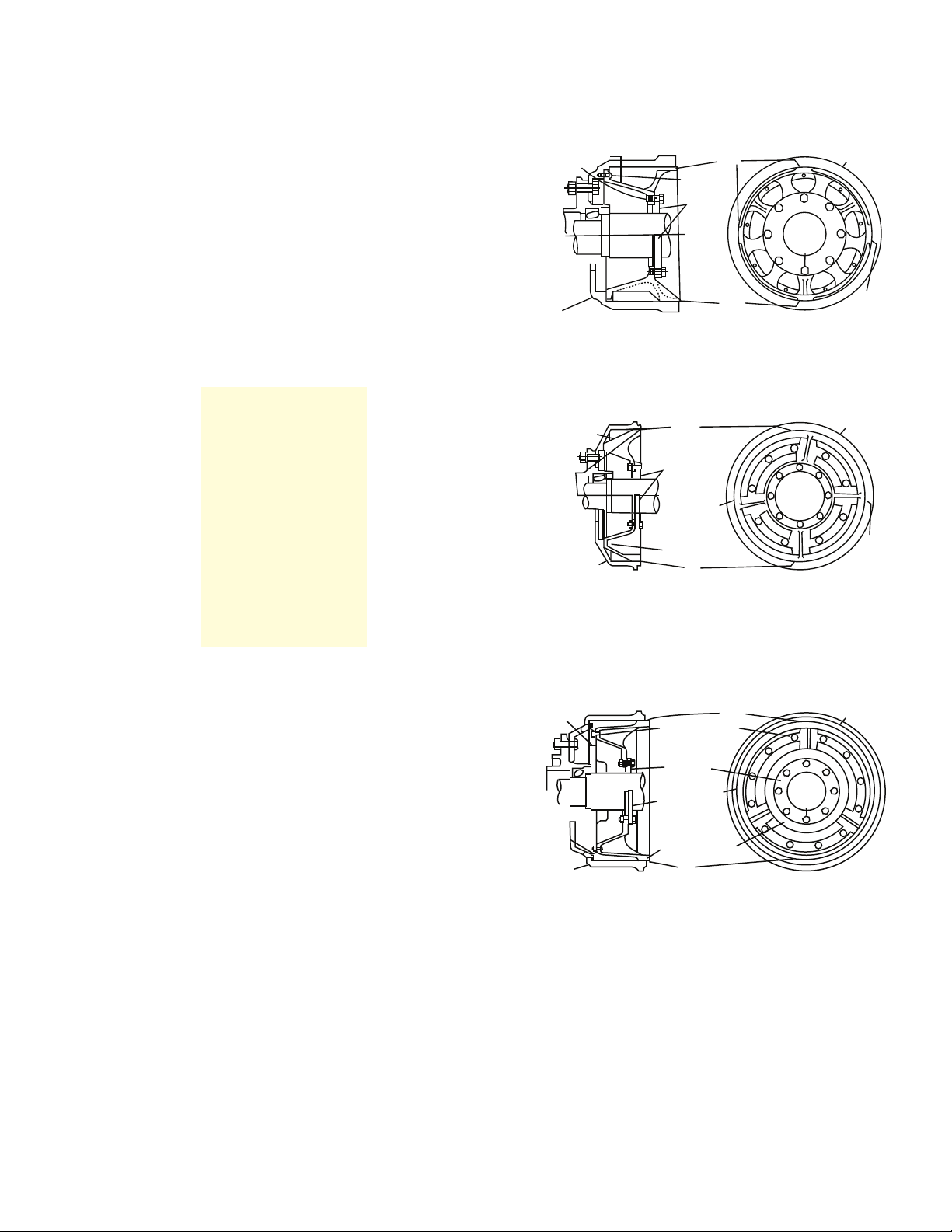
The main components of the Warner Electric Brake
are the backing plate or brake spider, magnet,
armature, brake band or brake shoes, cams and brake
drum; the nomenclature of the brake components
being dependent on method of fabrication, design,
and to some extent on brake size. With the
electro-mechanical actuating components (magnet
and armature) removed, (Figure 1-1), the brake consists
of a brake spider, which is mounted on the axle flange
and supports the brake shoes and cams. These
components are similar to, and functionally the same
as, those components found in all other mechanical
friction brakes.
The electro-mechanical actuating components
comprise a “friction clutch” and serve to generate the
force which multiplied by the cams, presses the brake
shoes into the brake drum. One plate of this “clutch” is
the armature, (Figure 1-2) which is bolted to the drum
and rotates with the wheel. The other plate of this
“clutch” is the magnet, (Figure 1-3) which is mounted
on the brake spider and is free to rotate a limited number of degrees in either direction. When the “clutch” is
engaged (upon application of an electric current to the
magnet) any movement of the trailer wheel (forward or
backward) causes the magnet to rotate and braking
results.
Figure 1-2
Armature Assembly
Brake Shoe
Cams
Figure 1-1
Electric Brake—Magnet Removed
Brake Spider
Dust Cover
Figure 1-3
Magnet Assembly
Warner Electric • 800-825-9050 819-0514
4
Page 5

Operation
How to Break in Trailer Brakes
When the magnet rotates, a trunnion, located on the
back of the magnet, moves the cam. The cam, bearing
on the brake shoe end, moves the brake shoe into
contact with the brake drum. After the toe end of the
brake shoe is forced against the brake drum, the shoe
(being free to float on its support and somewhat flexible in structure) will tend to follow the drum until the
complete brake shoe assembly is making contact with
the drum. The brake shoe is limited in its travel, however, since the heel end is forced against an anchor,
which is part of the brake spider assembly.
As the amount of current applied to the magnet is
increased, the attractive force between the magnet and
armature becomes greater. With an increase in attractive force between magnet and armature, more torque
is developed by the “clutch” and the pressure exerted
by the magnet trunnion upon the brake shoe (through
the cam) increases; and the shoe is pressed tighter into
the drum.
Until the vehicle is brought to a stop, slippage between
the magnet and armature occurs. However, if during a
stop sufficient pressure is built up, slippage between
the magnet and armature ceases and the entire unit
(magnet, armature, brake shoe, and brake drum) will
lock and slide the tire, providing the brake is of proper
capacity for the wheel load.
No brake adjustment is necessary. The magnet movement is sufficient to wear the brake lining down to the
rivet heads if the proper brake shoe to drum clearance
is maintained when new lining is present. When the lining has worn out, the cams come against a positive
stop (preventing further magnet rotation) preventing the
rivet heads from scoring the drum. Improper clearance
between brake shoe and drum initially will cause the
magnet to reach full travel before completely wearing
out the lining. In either case, as full magnet travel is
reached, a gradual loss of brake power will result.
Thus from the foregoing description, it is readily seen
that the Warner Electric Brake is a simple power-brake.
The amount of power developed being controlled by
the amount of current metered to the magnet by the
brake controls. Maximum power being achieved by an
amount of current approximately equal to that used by
a tail-lite.
When the armatures and magnets are new, to prevent
possible damage and to increase their efficiency, the
following steps should be followed during the initial
braking applications:
1. Attain a minimum vehicle speed of thirty miles
per hour and apply trailer brakes only until the
vehicle speed is retarded to approximately fifteen miles per hour, then release the brakes
allowing the vehicle to regain speed. DO NOT
LOCK THE WHEELS.
2. Next, drive for about one-half mile without
applying the trailer brakes. Repeat Step No. 1.
3. It will be necessary to follow Steps No. 1 and
2 until you have traveled approximately six
miles.
4. Allow the brakes to run free during the next
four miles. Then apply the brakes to check
their efficiency.
This procedure is also recommended whenever a
wheel has been pulled for maintenance of any kind or
when the trailer has set idle for any extended period of
time.
How to Apply Brakes
A brake is designed for a fixed capacity based upon
wheel load and tire size, and it is mounted in a minimum of space in order to clear springs and frames.
Considering this, it should not be required to handle
more than its own wheel load.
To obtain satisfactory trailer brake performance, the
towing vehicle’s brakes must handle their own load,
and therefore, must be applied simultaneously with the
trailer brakes. Consequently, the towing vehicle’s
brakes and the tractor trailer brake control system
must be kept in good repair to obtain maximum results
from the trailer brakes.
Overloading or using only the trailer brakes to stop the
complete tractor-trailer unit, will cause the heat absorption capacity of the brake to be exceeded. Hotter
brakes, longer stops, and shorter lining life will result.
Warner Electric • 800-825-9050 819-0514
5
Page 6

Section ll. Installation
Prepare Brake and Axle for Installation
The performance of an electric brake depends entirely
upon an accurate installation. Follow instructions, for
accuracy is definitely demanded and a brake properly
installed assures long life and dependable performance.
In preparing for installation, make certain that the hub
drum pilot (A, Figure 2-1) is at a perfect right angle with
the drum mounting surface (B), and that the drum pilot
(A) runs concentric with the axle spindle within .010”
total indicator reading. This may be checked on the
axle with a dial indicator or by removing the hub and
placing it in a lathe, using its own bearings on the
arbor for centering. If drum pilot bore and mounting
holes are not already present, bore drum pilot, allowing
a maximum of .004” clearance; and drill bolt holes,
using the hub as a template.
A
Axle
Figure 2-2
Checking Drum on Lathe
Install Flanges
If axle is equipped with brake mounting flanges suitable for installing electric brakes, clean flanges to
insure proper fit between flange and brake spider. If
axle is not equipped with flanges or old flanges are not
suitable for installing electric brakes, new flanges properly located - must be welded in position on the
axle. Cut off old flanges with a cutting torch leaving
axle clean and smooth.
Hub
B
Figure 2-1
Installing Drum on Axle
Install and Check Drum
Mount drum on hub and tighten securely. Check drum
for concentricity making certain that drum bore is concentric with axle spindle with .010” total indicator reading. Rotate drum on hub for best results. If drum is not
within concentricity limits, place hub and drum assembly in drum lathe (Figure 2-2) and remove the very minimum of stock which will permit drum to run within
concentricity limits. If it becomes necessary to remove
more than 1/32” from drum bore (diameter), remove
1/16” stock from drum and use oversized lining of
1/32” shim stock under lining to maintain proper drum
to lining clearance.
Select the correct brake mounting flange for the size of
brake to be installed.
#4604 for 15 x 3” brake
#40039 for 121⁄4 x 51⁄2” brake
#40039 for 161⁄2 x 5, 6, 7” brake
Mark the inside of the flange 1/16” larger than the actual size of the axle, (Figure 2-3). Cut the opening with a
cutting torch or turn out on a lathe. If opening in flange
is not large enough to permit assembly over axle collar,
cut flange in half with a hacksaw. Do not use a cutting
torch!
Mark 1/16”
larger than Axle
Saw Here
Figure 2-3
Installing New Mounting Flanges
Warner Electric • 800-825-9050 819-0514
6
Page 7
Kit 7494 Consists of:
Welding Fixture EQ-793
Mtg Accessory 111526
Shim
Axle
Flange
Welding Fixture
Bolted to Drum
Drum
Shim
Drum
Shim
Axle
Flange
Bolted To
Welding
Fixture
Kit 7494 Consists of:
Welding Fixture EQ-793
Mtg Accessory 111526
Shim
Axle
Flange
Axle
Flange
Welding Fixture
Bolted to Drum
Welding Fixture
Bolted to Drum
Drum
Shim
Drum
Drum
Drum
Shim
Shim
Shim
Shim
Shim
Axle
Flange
Bolted To
Welding
Fixture
Kit 7504 Consists Of:
Welding Fixture EQ-730
Mounting Acc. 11603
Kit 7494 Consists of:
Welding Fixture EQ-793
Mtg Accessory 111526
Shim
Axle
Flange
Axle
Flange
Welding Fixture
Bolted to Drum
Welding Fixture
Bolted to Drum
Drum
Shim
Drum
Drum
Drum
Drum
Drum
Shim
Shim
Shim
Shim
Shim
Shim
Shim
Shim
Axle
Flange
Bolted To
Welding
Fixture
Axle
Flange
Bolted To
Welding
Fixture
Kit 7504 Consists Of:
Welding Fixture EQ-730
Mounting Acc. 11603
Welding Fixture Bolted
To Armature Adapter
Axle Flange
Weld
Armature
Adapter
Welding Fixture No.
EQ-615-A
Armature Adapter
Indentification
16½ x 5 - 21⁄64”
16½ x 6 - 53⁄64”
16½ x 7 - 1-21⁄64”
Bevel edges of hacksaw cut to provide surface for
good weld.
If a 16-1⁄2 x 5, 6, or 7” brake is to be installed, bolt
armature adapter to the drum, (Figure 2-4).
Adapter #3979 for 16-1⁄2 x 5” brake
Adapter #3993 for 16-1⁄2 x 6” brake
Adapter #3942 for 16-1⁄2 x 7” brake
It is important that a thin coating of “Permatex” or
other suitable sealer be used between armature
adapter and brake drum to prevent grease from leaking
under adapter and getting into brake assembly.
Figure 2-4
Bolting Armature Adapter to Drum
Figure 2-5
Location of Welding Fixture Inside of Drum
(12-1/4 x 5-1/2” Brake)
Figure 2-6
Location of Welding Fixture Inside of Drum
(15 x 3” Brake)
Bolt the welding fixture inside of drum as illustrated in
Figures 2-5, -6, -7.
Figure 2-7
Location of Welding Fixture Inside of Drum
(16-1/2 x 5, 6, 7” Brake)
Bolt axle flange to welding fixture and install hub,
Fixture #EQ-615A (Figure 2-7) for 16-1⁄2 x 5, 6, 7” brake.
Fixture #EQ-793 (Figure 2-5) for 12-1⁄4 x 5-1⁄2” brake.
Fixture #EQ-730 (Figure 2-6) for 15 x 3” brake. If clearance between drum and fixture is present, center the
fixture in drum by using shims between fixture and
drum in four locations as shown.
drum, and welding fixture assembly in place on axle.
Pull wheel bearing lock nut tight. If flange has been cut
in half, insert shims (Figure 2-8) in hacksaw cut before
welding to prevent shrinkage. If grease seal is used as
Warner Electric • 800-825-9050 819-0514
a bearing spacer and is too large for flange or welding
fixture to pass over, put welding fixture and flange on
axle and assemble to drum after hub and drum assembly are placed on axle. Center welding fixture in drum
by using shims as illustrated in Figures 2-5, -6, -7.
7
Page 8
Shims
Figure 2-8
Location of Shims for Welding Flange
With an electric arc, tack both outer edges of hacksaw
cut, if cut is present. T
ack flange (Figure 2-9) to axle in
approximately four places. Complete weld by welding
hacksaw cut first - outer edge to axle - then make
continuous weld between flange and axle. Remove
bolts that hold flange to welding fixture and remove
hub, drum, and welding fixture from axle. Complete
weld on opposite side of flange. Remove welding
fixture from drum and clean all weld splatter from drum
or spindle surfaces.
Install Brakes
The desired position for mounting brakes on the axle is
indicated in Figure 2-10. Whenever possible they
should be mounted so that the brake spider anchor is
down and 45° to the rear as determined by forward
vehicle travel. Mounting brakes in this position affords
the best wheel bearing loading during application of
brakes. If the brakes are marked right and left hand
because of the type and location of lining segments in
brake shoes, the woven lining (with arrow indicating
drum rotation for forward vehicle travel) must always
be on the toe end of the shoe ring. Left and right hand
are determined by facing in the direction of forward
vehicle travel. In the event it is not possible to locate
the brake spider anchor as shown, the anchors must
be in the same relative location for all wheels.
For Brakes
Direction
of Travel
Marked Right
and Left Hand
Locate Woven
Lining on
Toe End
Tack Weld
Figure 2-9
Weld Points on Flange
NOTE: Do not use same hub and drum assembly as
template for all wheels. Use hub and drum
designated for each wheel location.
Brake
Spider
Anchor
45°
Figure 2-10
Brake Mounted in Correct Position
Install Armature in Drum
Bolt armature inside of drum (Figure 2-11). Armature
bolts directly to armature adapter for 16-1⁄2” series
brakes. On 12-1⁄4 x 5-1⁄2” and 15 x 3” brakes, grease
guard is placed between armature and drum when
armature is bolted in place. A thin coating of
“Permatex” or other suitable sealer must be used
between grease guard and drum at this time.
Warner Electric • 800-825-9050 819-0514
8
Page 9

Figure 2-11
Bolt Armature Inside of Drum
NOTE: Armatures are marked right and left hand,
and they must be installed accordingly.
Face in direction of forward vehicle travel to
establish right and left hand relationship.
Outside Legs
Middle
Movable
Frame
Thumb
Screw
Leg
Collar
Check Armature Depression
Before closing up the brake assembly by mounting
the wheel on the axle, check the armature depression.
Since the armature and magnet must run in light
contact at all times (the armature is spring mounted to
compensate for armature and magnet wear), it is
absolutely necessary that the proper magnet and
armature relationship, termed armature depression, is
maintained at all times. Because this relationship
between armature and magnet constitutes a blind
assembly, an armature depression gauge (Figure 2-12)
is used.
Gauge #40252 for 12-1/4 x 5-1/2” brake
Gauge #40252 for 15 x 3” brake
Gauge #4812 for 16-1/2 x 5, 6, or 7” brake
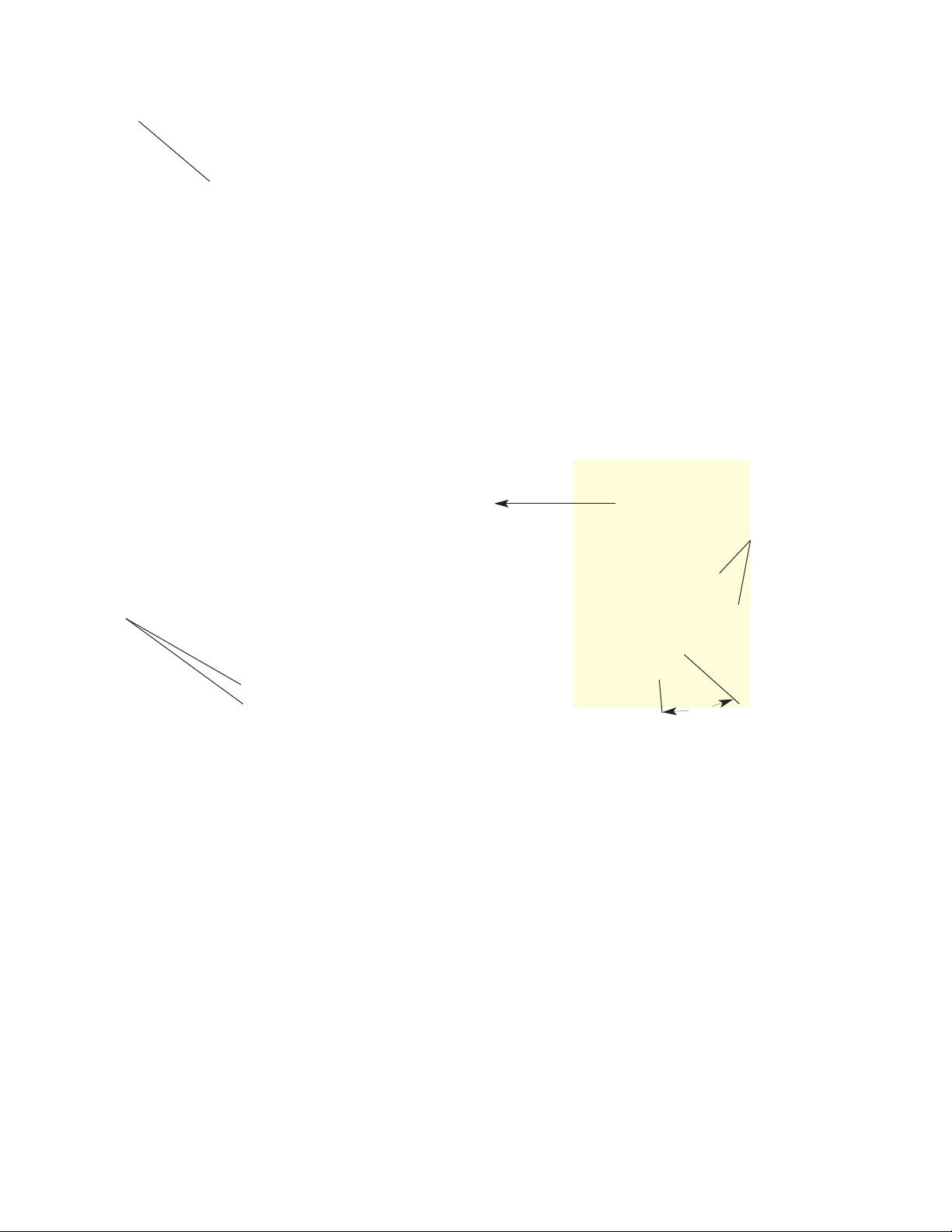
Step 1 To determine the amount of depression,
place the outside legs of the gauge against
the magnet facing with both thumb screws
loose and with collar on middle leg on the
outside of gauge crossbar (Figure 2-13).
Push the middle, movable leg into contact
with the bearing shoulder. Make certain that
the gauge is held perpendicular to the
magnet and that the magnet is flush against
the brake spider.
Magnet
Face
Bearing
Shoulder
Collar
Go-No-Go
Gauge
Thumb
Screw
Figure 2-12
Armature Depression Gauge
Figure 2-13
Using Depression Gauge—Step 1
Warner Electric • 800-825-9050 819-0514
9
Page 10

Figure 2-14
Using Depression Gauge—Step 2
Step 2 Next, tighten the frame thumb screw,
positioning the movable leg (Figure 2-14).
Move the collar up against the frame and
tighten the collar thumb screw fixing the
collar securely upon the movable leg.
Armature
Face
Bearing
Figure 2-16
Using Depression Gauge—Step 3
Step 4 Reverse the gauge so collar on center leg is
below gauge crossbar
, and place the outside
legs against the armature face (Figure 2-16).
Make certain gauge legs are on armature
face and not between segments or in
welding projection holes. Loosen the thumb
screw on the gauge frame only, and push the
movable leg against the bearing. Tighten the
gauge frame thumb screw fixing the movable
leg in this new position. Check this position
of the three legs in three points, 120˚ apart,
to insure correct reading.
Figure 2-15
Positioning Armature Disc
Step 3 With the wheel assembly lying down so that
the armature is horizontal, place the inner
bearing in the hub and rotate under light
Measuring Armature Depression
Figure 2-17
pressure to make certain bearing is fully
seated. Have someone hold the armature
disc (Figure 2-15) up against the stops or
place three wedges equally spaced under
the disc to hold it against the stops. Using
Step 5 The distance between the gauge frame and
the collar on the movable leg is the armature
depression (Figure 2-17). It should be
between 1/8” and 3/16”.
wedges is the more accurate method.
Warner Electric • 800-825-9050 819-0514
10
Page 11

Figure 2-18
Using GO-NO-GO Gauge
Adjust Armature Depression
If the depression is less than 1/8”, the difference must
be made up by placing shims (Figure 2-19) under the
armature retaining ring. If the depression is more than
3/16”, place a hardened bearing spacer between the
inner bearing and the bearing shoulder on the axle.
Warner Electric does not supply bearing spacers.
If wedges have been used under the armature to check
depression, be sure to remove them.
Cleaning
Step 6 The armature gauge is provided with a Go-
No-Go gauge (Figure 2-18) pr
esenting an
easy manner of checking for correct depression. The small end of the pin is 1/8” in diameter and should slip between the gauge
frame and the collar. The large end of the pin
is 3/16” in diameter and should not slip
between the gauge frame and collar.
Spacer No. 3516 1/16” thick For use with 12-1/4” x 5-1/2”
Spacer No. 3516A 1/32” thick and 15” x 3” Brakes
Spacer No. 3313 1/16” thick For use with 16” x 2-1/2”,
Spacer No. 3313A 1/32” thick 17-1/4” x 3”, 4”, 5”, and
16-1/2” x 5”, 6” and 7” Brakes
Clean all grease and oil from the brake drum surface,
armature face, magnet face, and brake lining with
carbon tetrachloride before mounting wheels. Pack
wheel bearings with a good grade of bearing grease.
Be sure wheel bearings are tight, as loose bearings
cause grabby, erratic brakes. Under no circumstances
should a grease gun be used; and if any grease fittings
are present, remove them and plug holes before
releasing the unit for service.
Electrical Connections
Make necessary electrical connections in accordance
with recommended wiring diagrams CWA-001 through
CWA-008 furnished separately.
Figure 2-19
Armature Retainer Ring Shims
Warner Electric • 800-825-9050 819-0514
11
Page 12

Section lll Maintenance
During preventive maintenance periods or when
attempting to diagnose brake troubles, three simple
checking procedures should be followed. Merely by
checking the current available for braking, the approximate amount of brake lining wear, and whether or not
the wheel bearings are tight; most brake troubles can
be pin pointed and the condition of the electric brake
system determined.
Check Current Available
Be sure that the electrical circuit of the towing vehicle
is connected to the electrical circuit of the trailer
(Figure 3-1). It is good practice to check and clean the
socket and plug contacts periodically to insure a clean,
tight connection.
Figure 3-2
Connecting Ammeter to Controller and Brake Wire
Make a light, fast application of the controller
(Figure 3-3) and observe the direction of movement
of the ammeter needle. If needle moves in wrong
direction, reverse the ammeter leads. Current of the
wrong polarity in excessive amounts can damage the
ammeter. When ammeter is correctly connected in the
brake circuit, make a full application of the controller,
noting the total current in the circuit as shown by the
ammeter. Move the load control from 100% to 0 and
observe movement of ammeter needle. There should
be a gradual reduction of current. Return load control
to 100% and note current reading. If same as previous
reading, load control is operating correctly.
Figure 3-1
Towing V
Remove either one of the brake circuit wires from a
controller terminal and connect a low reading DC
ammeter (15-25 amp. capacity) between the contr
terminal and the wire just removed (Figure 3-2). Make
certain load control is set at 100% (full on). Start
engine and idle fast enough to insure full battery
charge.
Warner Electric • 800-825-9050 819-0514
12
ehicle Electrical Connection
oller
Figure 3-3
Checking Circuit Curr
To determine whether proper current is available for
braking, refer to Table l- Magnet Current Rating.
ent
Page 13

Table l - (Magnet Current Rating)
Brake Size
Brake Size
6 Volt 12 Volt 6 Volt
12-1/4 x 5-1/2” 3.7-4.1 3.0-3.7 *16 x 2-1/2” 3.4-3.8
15 x 3” 3.7-4.1 3.0-3.7 *17-1/4 x 3 & 4 3.0-3.4
16-1/2 x 5*, 6*, 7” 3.4-3.8 2.6-3.2 *17-1/4 x 5 4.0-4.5
AMPS
* Not in production - service parts only.
When the towing vehicle has a 6-volt electrical system,
all brakes will be connected in parallel; therefore, the
total current in the brake circuit should be equal to the
number of brakes times the value given in Table l.
If the reading at the controller is higher than the maximum based on Table l, check for a short in the wiring,
cable, controller, or brake magnets (Figure 3-4). If the
reading at the controller is less than the minimum
based on Table l, check the complete electrical circuit
If the towing vehicle has a 12-volt electrical system, all
single axle trailers will be wired in parallel; and the total
current in the brake circuit, should again be equal to
the number of brakes times the value given in Table l.
However, if the trailer is a tandem axle trailer, all brakes
may be wired in parallel or the brakes on each axle
may be wired in series and the axles wired in parallel. If
for loose or dirty connections, broken wires, improper
wire size, and conformity of wiring arrangement with
Warner Wiring Diagrams. If towing vehicle has a 12-volt
electrical system, check to make certain proper external resistor is being used. All splices and terminals
should be soldered and ground connections made at
battery or welded to the frame.
all brakes on a tandem axle trailer are in parallel. the
total current in the brake circuit should be equal to the
number of brakes times the value given in Table l. If, on
a tandem axle trailer, the brakes on each axle are wired
in series and the axles are wired in parallel, the total
current in the brake circuit should be equal to that of a
single axle trailer wired in parallel.
AMPS
Figure 3-5
Checking Amperage at Brake Magnets
Figure 3-4
Checking Electrical Connections
Warner Electric • 800-825-9050 819-0514
13
Page 14

Check Amperage at Each Brake
“A”
“A” Measured
Here
Inside
Rim Dia. “D”
Check for Lining Wear
Amperage check at the controller should be followed
by an individual amperage check at each brake magnet
(Figure 3-5). When all brakes are connected in parallel,
connect the ammeter between either of the brake terminals and the wire removed from that terminal. Make
light, fast controller application to insure that meter is
properly connected into brake circuit with respect to
polarity. The reading at each brake should be the same
and equal to the value given in Table I. If brakes are
connected in series on a given axle (tandem axle trailer
and 12-volt tractor), current per axle is equal to one
magnet based on Table I. To check each individual
magnet when series is connected, disconnect both
leads from one brake and connect ammeter between
the two leads. The reading per magnet should be
double that given in Table I. If current reading for any
one brake is incorrect, inspect for broken wires, dirty
or loose connections and shorts. Failure to find fault
externally, when brake amperage is incorrect, will
necessitate removal of wheel for further inspection.
To check for lining wear, apply the tractor hand controller full on and back up the unit to set the trailer
brakes hard. Do not release the brake, but mark the rim
as indicated in Table II, page 15. Without releasing the
brake, move the unit forward to set the trailer brakes
hard, and again mark the rim as indicated in Table II.
Measure the dimension “A” on the curve of the rim.
Note: The differences in loading and method
of measuring give only approximate results
which should be close enough to determine
whether the magnet is approaching
maximum travel and/or the lining is worn out.
For greater accuracy, it may be necessary to
disconnect all brakes except one and check
each wheel individually. After setting brake
as above, ease clutch off so as to allow
deflection of trailer suspension, caused by
brake application, to release.
If maximum travel based on Table II has been reached
and loss of brake power has been experienced, wheels
should be removed and the brakes relined.
Table II — Lining Wear
Nom.
Tire
Rim
Size
14
“D”
(in.)
15 14.7 7.8 8.15
16 15.7 7.3 8.7
18 17.6 6.5 9.75 8.6
20 19.6 5.85 10.8 9.6 6.0 11.3 9.1 12.3
22 21.6 5.3 10.5 6.6 12.45 10.0 13.5
24 23.7 4.87 11.6 7.25 13.65 10.9 14.8
Warner Electric • 800-825-9050 819-0514
C
“A” Maximum
12-1/4 x 5-1/2 15 x 3 16 x 2-1/2 16-1/2 x 5, 6, 7 17-1/4 x 3 17-1/4 x 4, 5
Page 15

Check For Loose Wheel Bearings
Inspect Drums
During brake inspection periods and before removing
wheels, jack up each wheel and check for loose wheel
bearings (Figure 3-6). If by using a bar under the tires,
the wheels can be moved up and down on the axle the
wheel bearings are loose or worn. This condition can
cause grabby or noisy brakes, a dragging brake which
creates undue heat and rapid lining wear, or a possible
wheel lockup. Bearings Must Be Kept Snug.
Figure 3-6
Checking for Loose Wheel Bearings
Before relining brakes or during regular maintenance
periods, the drum should be checked for an
out-of-round condition. This may be accomplished
by an inside micrometer or a dial indicator mounted
on a stub spindle (Figure 3-8). Drums should not be
out-of-round more than .010”, since such a condition
can cause erratic, grabby brakes and possible difficulty
in assembling the wheel onto the axle.
Whenever a wheel is removed, always check the drum
mounting bolts. They must be kept tight, since a loose
drum has the same effect as loose wheel bearings. A
loose drum may also cause the drum mounting bolts to
shear off during a brake application.
When wheels must be removed for maintenance or
, always check for worn or defective bearings and
repair
cups (Figure 3-7). Defective parts must be replaced.
Also check the hub for cracks and for proper fit of the
bearing cups in the hub.
Figure 3-7
Inspecting Wheel Bearings
Figure 3-8
Checking Drum with Inside Micrometer
and Dial Indicator
Warner Electric • 800-825-9050 819-0514
15
Page 16

Check drums for excessive heat checking and scoring.
Heat checking may be a sign of an undersized brake, a
dragging brake, or an unbalanced brake condition in
the tractor-trailer unit. Heat checking will also be
accompanied by excessive brake lining wear. If the
brake drum is scored, check for loose lining rivets or
foreign metal particles imbedded in the lining. Drums
which have excessive heat checking or scoring should
be turned.
Drum and Lining Clearance
Caution should be exercised when boring drums and
relining shoes as there is no definite yardstick to follow
as to how much a drum may be oversized. It is
generally recommended that a drum shall not be bored
oversize more than 1/4” on the diameter and that shim
stock thicker than 1/8” shall not be used with riveted
lining. In some operations, such as mountainous
terrain, it is recommended that drums be replaced
before this time. In order that peak brake efficiency be
obtained, use only factory approved and tested lining
as covered by Charts I-26011 and I-26012 in the
replacement parts section of this manual.
Since the electric brake cannot be adjusted to
compensate for drum and lining wear, clearance
between drum and lining is one of the most important
factors governing electric brake operation. This
clearance is best controlled at the initial installation,
during re-lines, and during drum replacement. If proper
clearance between drum and lining is maintained at
these times, the electric brake is so designed that the
lining will be completely worn out by the time the
maximum cam travel is reached. However, if too much
clearance is present initially, maximum cam travel will
be reached before the lining is completely worn out
and a gradual loss of brake power will result. Too little
clearance initially may cause a brake to drag with a
possible wheel lockup, or make it difficult to assemble
the wheel onto the axle. Considerable variation in drum
to lining clearance between brakes on a given unit
could cause unbalanced braking.
Relining Brakes
Brake shoe and lining assemblies as received from
the factory are ground to give a drum to lining
clearance of approximately .020” (.040” on the
diameter) with respect to the nominal brake diameter.
When relining or replacing a drum, the drum bore and
overall lining diameter (Figure 3-9), should be matched
to obtain approximately .020” clearance. Table III will
serve as a guide for obtaining proper clearance.
Do not weld metal to band ends to compensate for
drum wear, excessive drum to lining clearance, or wear
of brake components.
Always check the brake shoe assembly for worn loose
or greasy lining. If any of these conditions exists,
replace with Warner recommended lining. The high
radial pressures developed by the brakes will cause too
soft a lining to wear rapidly, often causing damage to
the drum and the brakes to fade under heat. Where
greasy lining is encountered, inspect and replace
grease seals. If enough grease is present, it may be
necessary to remove the grease guard or armature
adapter and clean grease from wheel and drum. When
replacing the grease guard or armature adapter, a thin
coating of “Permatex” or other suitable sealer must be
used between adapter and drum. Surface grease on
lining, drum braking surface, magnet, and armature can
be removed with carbon tetrachloride or other suitable
solvent. However, if grease has penetrated lining or
magnet facing, they must be replaced since grease will
seep to the surface under heat causing weak brakes.
Figure 3-9
Measuring Band Size with Outside Micrometers
Warner Electric • 800-825-9050 819-0514
16
Page 17

Table III - Drum Rebore and Brake Reline Tolerances
Brake Size Brake Shoe Dia.
12-1/4 x 5-1/2”
15 x 3
16 x 2-1/2
16-1/2 x 5, 6, 7
17-1/4 x 3, 4, 5
11.442 0.385 —
11.450 0.400 —
14.300 0.325 —
14.310 0.330 —
15.4370 0.265 —
15.4375 0.275 —
15.682 0.390 —
15.692 0.400 —
16.370 0.385 —
16.375 0.405 —
When brakes are relined, but the drum is not turned;
the ridge left on the bell end of the drum, due to drum
wear on the drum braking surface, should be removed.
This may be accomplished by turning or by using a
hand grinder (Figure 3-10) with a flexible disc.
Replacement Lining Thickness Tolerances
Standard Oversize
Check Magnet And Armature
Make certain that proper magnet and armature
relationship is being maintained. That is, the magnet
poles should always be in contact with the armature
(metal to metal). This is initially accomplished by
undercutting the magnet facing .005 to .007” below
the magnet poles (Figure 3-11) at the factory. This
insures that the magnet poles will be fully seated in
their armature tracks before the magnet facing comes
into contact with the armature. Normally the magnet
pole tracks in the armature should be only slightly
wider than the magnet poles. If excessively wide tracks
are present on the armature, a loose drum or loose
wheel bearings are usually at fault.
Magnet Poles
Magnet Facing
Armature
Undercut .005” to .007”
Figure 3-10
Removing Ridge on Drum
Magnet Shell
Figure 3-11
Cross Section of Magnet and Armature
Warner Electric • 800-825-9050 819-0514
17
Page 18

During normal operation, the face of the armature and
New
Slightly Scored
(Normal)
Badly Scored
(Needs Replacement)
magnet will become scored or grooved to some extent
(Figure 3-12). This condition is not detrimental and
does not show excessive wear or defective parts. In
the case of some magnets, termed “air gap” and
distinguished by an expansion groove in the magnet
facing, a ridge will appear on the armature opposite
this groove after considerable wear. It is recommended
that the ridge be partially ground off, so that at
maximum wear, it cannot cut through the magnet
facing and short out the magnet coil.
Figure 3-12
Typical Wear Patterns
Often times, when there is a complaint of weak brakes
and all other things appear normal, a glazed magnet
facing is at fault or a condition exists whereby the
magnet facing prevents the magnet poles from coming
into direct contact with the armature. This condition
may be remedied by placing the magnet in a lathe
(Figure 3-13) and undercutting the magnet facing
(Do Not machine the magnet poles) with a carbon
tipped tool or by using a small piece of sandpaper
(Do Not use emery cloth) on the finger tips or on a
small block of wood. Whenever possible, use only
sandpaper; undercutting the magnet facing in a lathe
reduces magnet wear life.
Figure 3-13
Undercutting the Magnet Facing
Replacement of Magnets and Armatures
Note: All single wire magnets are replaceable
with 2 wire magnets by grounding one wire
to the brake.
Table IV is a guide to determine when magnet and
armature should no longer be refaced. As indicated
magnets and armatures may be used even when
dimensions “A” and “B” are below the minimum;
but they should never be refaced when below this
minimum. If a magnet needs to be replaced, a new or
refaced armature must be used. However, an armature
may be replaced without replacing the magnet. In this
case, merely make certain the magnet facing is below
the magnet poles to insure proper pole contact initially.
Warner Electric • 800-825-9050 819-0514
18
Page 19

Magnets
“A”
“A”
Air Gap
Non-Air
Gap
Armatures
Air Gap Type
(AG)
“B”
“B”
Non-Air Gap Type
(NAG)
Do Not Reface Armature if Min.
Thickness is Less Than Dim. “B”
Do Not Reface Magnet if Min.
Thickness is Less Than Dim. “A”
Table IV — Magnet and Armature Wear
Magnet and Armature can be used if dimensions “A” and “B” are below minimum given, but they should not be refaced after
minimum dimensions are reached.
Brake Size
Magnet
AG=Air Gap
NAG=Non Air
Gap
Dim.
A
Armature
AG=Air Gap
NAG=Non Air
Gap
Dim.
B
No. Type No. Type
12-1/4 x 5-1/2 40122 2 wire AG 1-15/64 4998A, 9A NAG 27/64
15 x 3 40110 2 wire AG 1-7/32 4998A, 9A NAG 27/64
16 x 2-1/2
16-1/2 x 5, 6, 7
17-1/4 x 3, 4
17-1/4 x 5
4696
4752
4752A
40040
40092
4653
4750
40031
40093
4653
4708
40091
40013
40090
1 wire NAG
2 wire NAG
2 wire AG
2 wire AG
2 wire AG
1 wore NAG
2 wire NAG
2 wire AG
2 wire AG
1 wire NAG
2 wire NAG
2 wire AG
1-9/32
1-9/32
1-9/32
1-13/32
1-13/32
1-9/32
1-9/32
1-9/32
1-9/32
1-9/32
1-9/32
1-9/32
4655C, 6C
4655C, 6C
40045-6
40047-8
40047-8
4597A, 8A
4597A, 8A
40019-20
40019-20
4597A, 8A
4597A, 8A
40019-20
AG
AG
NAG
NAG
NAG
AG
AG
NAG
NAG
AG
AG
NAG
3/16
3/16
3/8
27/64
27/64
3/16
3/16
25/64
25/64
3/16
3/16
25/64
NOTE: All single wire magnets are replaceable with 2 wire
Warner Electric • 800-825-9050 819-0514
magnets by grounding one wire to the brake.
19
Page 20

Non-Air Gap Magnet
Air Gap Magnet
Air Gap Armature
Figure 3-14,
Types of Magnets and Armatures
It is important that magnets and armatures be used
in pairs (Figure 3-14), both from a wear pattern
standpoint and for proper electrical characteristics.
Therefore, during repair and maintenance periods,
never interchange magnets and armatures. When
new magnets and armatures are to be replaced,
either individually or in pairs, make certain that proper
electrical characteristics will be obtained. Thus, either
the magnet or armature must have an air gap in order
to insure proper brake release. If both magnet and
armature have an air gap, weak brakes will result.
Always order replacement parts by the number
stamped on the armature retainer ring or the magnet
nameplate.
Check the magnet bushing for damage or excessive
wear. A new bushing is approximately 1/16” thick and
should not be used when worn below 1/32”. Worn
bushings may be removed by driving a “prick punch”
between magnet and bushing. Install new bushing by
placing the magnet face down on a clean, smooth
surface and pressing the bushing into the magnet 1/4”
below the level of the magnet surface facing you.
Remove any rough edges with a bearing scraper.
Non-Air Gap Armature
If, during the amperage check at each wheel a
defective magnet was indicated, the magnet leads,
backing plate terminals, and backing plate terminal
block should be inspected. Defective parts should be
replaced and all connections cleaned and tightened. If
the trouble is not readily apparent, remove the magnet
for further checking.
Testing Magnet
Figure 3-15
Testing Amperage Capacity of Magnet
Warner Electric • 800-825-9050 819-0514
20
Page 21

Copper Clips
Test the magnet for amperage capacity by using an
ammeter and a 6-volt battery (Figure 3-15). The
ammeter should indicate the amperage value given
on the magnet nameplate, plus or minus 10%. The
magnet amperage is rated at 70°F; therefore, a hot
magnet will indicate slightly lower and a cold magnet
will indicate slightly higher. If amperage reading is
incorrect, the magnet should be replaced, after first
making certain that the magnet leads are not defective
and that the magnet leads are making a good positive
connection with the magnet coil.
To test the magnet for a ground, connect an ammeter
and a 6-volt battery to the magnet (Figure 3-16). If any
amperage is indicated, a grounded condition exists.
The ground may be in either the leads or within the
magnet itself; therefore, check the leads thoroughly
before replacing magnet. Old style magnets having a
single magnet lead have one coil lead grounded to the
magnet shell; and therefore, will indicate proper
amperage when tested in this manner if not defective.
Coil Leads
Steel Clips
Figure 3-17
Installing Magnet Lead Wires
Straighten coil leads. Remove the old magnet lead
assembly and replace with new. Bend steel clips tight
against the fiber insulator and magnet leads. Fit the
magnet coil leads into the copper clips, secure coil
leads in clips, and solder (Figure 3-18). Use caution in
soldering to prevent excess solder from grounding coil
leads to magnet shell.
Figure 3-16
Testing Magnet for Ground
Replacing Magnet Leads
When magnet leads are found to be defective, they
can readily be replaced in the field. Refer to the repair
parts section for correct magnet lead to be used, or
order leads by magnet number and brake size.
Where magnet lead wires are soldered to the magnet
coil, it will be necessary to replace the complete
magnet lead assembly whenever one of the leads is
found to be defective. Pry up the two steel clips which
hold the magnet leads to the magnet shell, just enough
to slide wire out (Figure 3-17). Use a soldering iron to
melt solder on terminals and open copper clips holding
magnet coil leads.
If magnet lead wire is mechanically connected, pry up
steel clip holding lead to magnet shell, remove screw
fasteners, and remove defective lead. Clean magnet
coil lead and all contact surfaces.
Figure 3-18
Soldering Magnet Lead Wires
Warner Electric • 800-825-9050 819-0514
21
Page 22

Steel Clip
Ceramic
Terminal
Block
Figure 3-19
Removing Leads from Ceramic Block
Replace with new lead and bend steel clip to clamp
lead to magnet. Cover connection with Glyptal or other
suitable sealer.
On magnets having a ceramic terminal block for
magnet lead connections, minor repairs to the terminal
block may be made by using a suitable ceramic filler. If
the ceramic block is damaged extensively, use a hack
saw, and cut through the steel clip holding the block in
place. Remove screws, and other attaching parts
holding magnet leads in place and straighten magnet
coil leads. Use extreme caution and bend steel clip up
(Figure 3-19) and slightly to the rear to permit removal
of remainder of terminal block. Clean magnet coil leads
and all contact surfaces of screw, and other attaching
parts, before inserting new terminal block. Bend steel
clip back in place to clamp terminal block to magnet,
and re-assemble magnet leads (Figure 3-20). If steel
clip is damaged during repair, it may be replaced by
welding new clip in place if extreme care is used to
prevent damage to magnet coil and coil insulation from
over-heating. Do not allow weld splatter to get on
magnet poles. Test magnet for short or ground after
any attempt at welding.
Figure 3-20
Installing Leads in Ceramic Block
While wheel is removed, blow out brake assembly with
air hose, making certain that all wheel bearings and
bearing surfaces are pr
otected. Check the magnet and
brake cams for movement; removing and cleaning
thoroughly if necessary. Check magnet and band return
springs for damage or loss of tension. Springs will lose
tension after considerable use due to heat; therefore, it
is recommended that at each reline all springs be
replaced. Never use diagonal cutters to remove or
replace springs.
Before replacing the wheel, always check the armature
depression. Follow the procedure outlined in the brake
installation section beginning with Figure 2-12. While
checking depression, check to make certain armature
face is parallel with the armature mounting ring. To do
so, measure the highest extended height of the
armature face at each armature stop. Pry up armature
stops, which are low if necessary.
Clean all grease and oil from the brake drum surface,
armature face, magnet facing and poles, and brake
lining with carbon tetrachloride. Pack wheel bearings
with a good grade of bearing grease and mount wheel
and drum assembly on axle. Draw up wheel bearing
lock nut tight enough to avoid loose wheel bearings.
Warner Electric • 800-825-9050 819-0514
22
Page 23

Warner Electric • 800-825-9050 819-0514
23
Page 24

Warranty
Warner Electric LLC warrants that it will repair or replace (whichever it deems advisable) any
product manufactured and sold by it which proves to be defective in material or workmanship
within a period of one (1) year from the date of original purchase for consumer, commercial or
industrial use.
This warranty extends only to the original purchaser and is not transferable or assignable without
Warner Electric LLC’s prior consent.
Warranty service can be obtained in the U.S.A. by returning any defective product, transportation
charges prepaid, to the appropriate Warner Electric LLC factory. Additional warranty information
may be obtained by writing the Customer Satisfaction Department, Warner Electric LLC, 449
Gardner Street, South Beloit, Illinois 61080, or by calling 815-389-3771.
A purchase receipt or other proof of original purchase will be required before warranty service is
rendered. If found defective under the terms of this warranty, repair or replacement will be made,
without charge, together with a refund for transportation costs. If found not to be defective, you
will be notied and, with your consent, the item will be repaired or replaced and returned to you
at your expense.
This warranty covers normal use and does not cover damage or defect which results from
alteration, accident, neglect, or improper installation, operation, or maintenance.
Some states do not allow limitation on how long an implied warranty lasts, so the above limitation
may not apply to you.
Warner Electric LLC’s obligation under this warranty is limited to the repair or replacement of the
defective product and in no event shall Warner Electric LLC be liable for consequential, indirect,
or incidental damages of any kind incurred by reason of the manufacture, sale or use of any
defective product. Warner Electric LLC neither assumes nor authorizes any other person to give
any other warranty or to assume any other obligation or liability on its behalf.
WITH RESPECT TO CONSUMER USE OF THE PRODUCT, ANY IMPLIED WARRANTIES WHICH
THE CONSUMER MAY HAVE ARE LIMITED IN DURATION TO ONE YEAR FROM THE DATE OF
ORIGINAL CONSUMER PURCHASE. WITH RESPECT TO COMMERCIAL AND INDUSTRIAL
USES OF THE PRODUCT, THE FOREGOING WARRANTY IS IN LIEU OF AND EXCLUDES ALL
OTHER WARRANTIES, WHETHER EXPRESSED OR IMPLIED BY OPERATION OF LAW OR
OTHERWISE, INCLUDING, BUT NOT LIMITED TO, ANY IMPLIED WARRANTIES OF
MERCHANTABILITY OR FITNESS.
Some states do not allow the exclusion or limitation of incidental or consequential damages, so
the above limitation or exclusion may not apply to you. This warranty gives you specic legal
rights and you may also have other rights which vary from state to state.
Changes in Dimensions and Specifications
All dimensions and specications shown in Warner Electric catalogs are subject to change without
notice. Weights do not include weight of boxing for shipment. Certied prints will be furnished
without charge on request to Warner Electric.
Warner Electric LLC
31 Industrial Park Road • New Hartford, CT 06057
815-389-3771 • Fax: 815-389-2582
www.warnerelectric.com
AA-110 819-0514 4/06 Printed in USA
 Loading...