

Page 1

P-2073-WE
SM314gb - rev 01/08
Multi Disc Torque Limiters
L331 VAR00 and VAR05
Service Manual
Page 2

We, WARNER ELECTRIC EUROPE, 7, rue Champfleur, B.P. 20095, F-49182 St Barthélemy d’Anjou Cedex
declare that the torque limiters made in our factory from St Barthélemy d’Anjou,
and hereafter designated : L331
are exclusively designed for incorporation into a machine and to be assembled with other equipments to create a machine. The operation of
the product is submitted to the conformity of the complete equipment, following the provisions of the machinery directive 98/37/EC.
Drawn up in St Barthélemy d’Anjou, July 2002 E.
PRAT, General Managing Director
CONTENTS
1 Technical specifications 2
1.1 Features 2
2 Precautions and restrictions on use 2
2.1 Restrictions on use 2
2.2 Precautions and safety measures 2-3
3 Installation 3
3.1 Transport - storage 3
3.3 Handling 3
4 Maintenance 4
4.1 Maintenance 4
4.2 Dismantling / Reassembling 4
4.3 Spare parts 4
4.4 Important recommendations 4
5 Appendix 5
5.1 Drawings / Description VAR00 5
5.2 Drawings / Description VAR05 6
3.4 Setting up 3
1 Technical specifications
1.1 Features
Units are delivered with “Z” dimension (see chart) factory set, for catalogue nominal
sliding torque : Cn ± 20% (Except specific requests for torque adjustment)).
Size Table 1 50 100 200 400 800 1600 3200 6400 12800
N max. RPM
«Z» dimension mm
«Z max.» dimension mm
VAR00 dimension kg
VAR05 - E dimension mm
VAR05 Weight kg
4800
0.8
4
4.2
+2/0
26
9.7
3800
1.5
4
5.8
+2.2/0
30
9.7
3200
1.6
4
7.3
+2.2/0
30
18.1
2700
2.1
5
10.1
+2.6/0
35
24.4
2200
16.2
40
36.8
3
6.5
+3/0
1900
3.5
6.5
28.4
+3/0
45
61.4”
1600
2.9
6.5
37.4
+3.4/0
45
71.4
1300
3.7
8
75
+4.2/0
55
142
1000
4
11
162
+5.7/0
75
344
NB : data for catalogue equipment .
Symbol designating
an action that might
damage the brake
Symbol designating an
action that might be
dan gerous to human safety
Symbol designating an
elec trical action that might be
dangerous to human safety
2 Precautions and restrictions on use
2.1 Restrictions on use
If maximum rotation speeds are exceeded, the guarantee is no longer valid.
2.2 Precautions in use and safety measures
During maintenance work, ensure that the mechanism to be driven by the units is at rest and that there is no
risk of it being started accidentally. All intervention have to be made by qualified personnel, owning this
manual.
2 Warner Electric Europe • +33 (0)2 41 21 24 24 P-2073-WE • 11/12
Page 3

Any modification made to the unit without the express authorisation of a representative of Warner Electric,
in the same way than any use out of the contractual specifications accepted by “Warner Electric”, will
result in the warranty being invalidated and Warner Electric will no longer be liable in any way with regard to
conformity.
3 Installation
3.1 Transport / storage
These units are delivered in standard packaging that will keep it intact for a period of 6 months during
ground, air or sea transport towards neighbouring continents (without crossing the tropics).
3.2 Handling
Avoid any impact on the units so as not to alter their performance.
The hub (515) is normally supplied at tolerances H7 for the bore and P9 for the width of the keyway (In
accordance with NF E 22-175/DIN 6885/BS 4235/ISO R773).
We recommend a tolerance h6 for the shaft. Slide the hub (515) on the shaft (after adjusting the keyway).
Never directly strike the hub (515), use a soft alloy part between these parts and the assembly device used.
Fix then the hub with socket cap head screws or bolts.
After tightening to torque, do not forget to secure the bolts fixing the hub (508) with Loctite 243 or an
equivalent type of product.
3.3 Setting up
The adjustment of the limiter to a given torque is obtained by displacement of the pressure flange ( 362), by
action on the axial fixing screws (905), after having loosened the setting screws (902).
• higher torque : moving the flange toward the interior
• lower torque : moving the flange toward outside
Check that dimension “Z” between the pressure flange (362) and the face of the hub (508), is adjusted a
tolerance of ± 0,1 mm.
Ensure, by some manoeuvres, that the slip torque is in line with the requested value.
Going beyond the value of dimension “Z max.” (Table 1), could generate a blocking of the limiter and a risk of
danger for the operator.
During maintenance work, ensure that the mechanism to be driven by the units is at rest and that there is no
risk of it being started accidentally. All intervention have to be made by qualified personnel, owning this
manual.
Warner Electric Europe • +33 (0)2 41 21 24 24 P-2073-WE • 11/12 3
Page 4
4 Maintenance
4.1 Maintenance
After some sliding (function of the use), the value of the transmitted torque decreases. Periodicaly check the
transmitted troque, and the state of the stack of discs.
4.2 Dismantling / reassembling
During maintenance work, ensure that the mechanism to be driven by the units is at rest and that there is
no risk of it being started accidentally. All intervention have to be made by qualified personnel, owning this
manual.
Dismantling:
• Dismantle the driving part of the receving part
• Reduce the spring pressure (740), unscrewing the fixing screws (905), then remove the
pressure flange (362)
• Remove the cover (531), the bearing housing (533) and the bearing (803)
• Remove the worn disc set
• Fit a new disc set
Immerse the new stack of discs, in oil (see table 2), for about 12 hours.
• Inspect bearings (806) (803) and (801), replace if required
4.3 Important recommendations
The types of oil to be used for lubricating the discs should meet the following criteria:
• Good rust resistance
• No friction modifying additive
• No additive that might corrode the bronze friction surfaces (1a or 1b NF M 07-015)
• High viscosity index (>80)
The oils listed below (see table 2) meet these characteristics. The list is not exhaustive and other lines may be
added to it. The viscosity of the oil to be selected varies depending on the running temperature and speed.
4.4 Spare Parts
All orders for spare parts must state the size of the unit with its code number, the reference number of the
part (see appendice), and the quantity of each component wanted.
Size Mineraloil ATF
Viscosity
Running Speed
BP
ESSO
MOBIL
SHELL
ELF
ISO VG 22
> 12 m/s
Nuto H22
DTE 22
Tellus 22
ISO VG 32
> 12 m/s
Energol HLP-D32
Nuto h 32
DTE Oil Light
Tellus 32
Polytelis 32
ISO VG 46
> 12 m/s > 12 m/s
Energol HLP-D46
Nuto H 46
Autran MBX
AT Dexron II
DTE Oil Medium
Tellus 46
Donax TM Elfmatic
Polytelis 46
ATF 220
G2”
Table 2
4 Warner Electric Europe • +33 (0)2 41 21 24 24 P-2073-WE • 11/12
Page 5
740508
706
362
515
806
947
715
309
948735
370 303 533 531
803
717
949
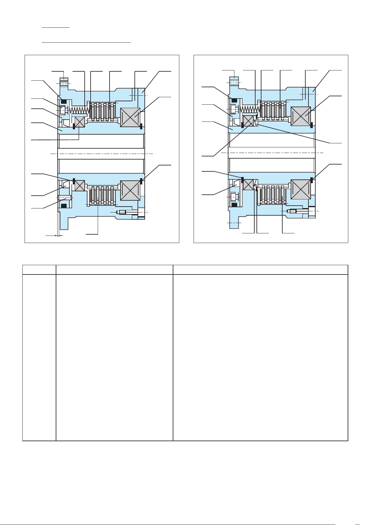
5 Appendix
5.1 Drawings / Description VAR00
740508
310 303 533 531
706
905
362
803
706
362
740508
370 303 533 531
803
515
801
949
947
715
902
Z
Ref. Nr Description Remarks
303
309
310
362
370
508
515
531
533
706
715
717
735
740
801
803
806
902
905
947
948
949
Steel outer disc
Steel inner disc
Thrust disc
Pressure ange
Pressure ring
Hub
Hub
Cover
Bearing housing
O-ring seal
Radial oil seal
V-ring
Deector
Spring
Ball bearing
Centering ball bearing
“Needle bearing
Setting screw
Axial xing screw
Outside circlips
Inside retainer
Outside retainer
309
x
x
Size 100-200-400-800
x
Size 1600-3200-6400-12800
x
x
x
x
x
x
Sizes 6400-12800
Sizes 6400-12800
x
Sizes 50-100-200-400-800
x
Sizes 1600-3200-6400-12800
x
x
x
Sizes 6400-12800
x
515
806
947
715
948735
717
949
309
Warner Electric Europe • +33 (0)2 41 21 24 24 P-2073-WE • 11/12 5
Page 6
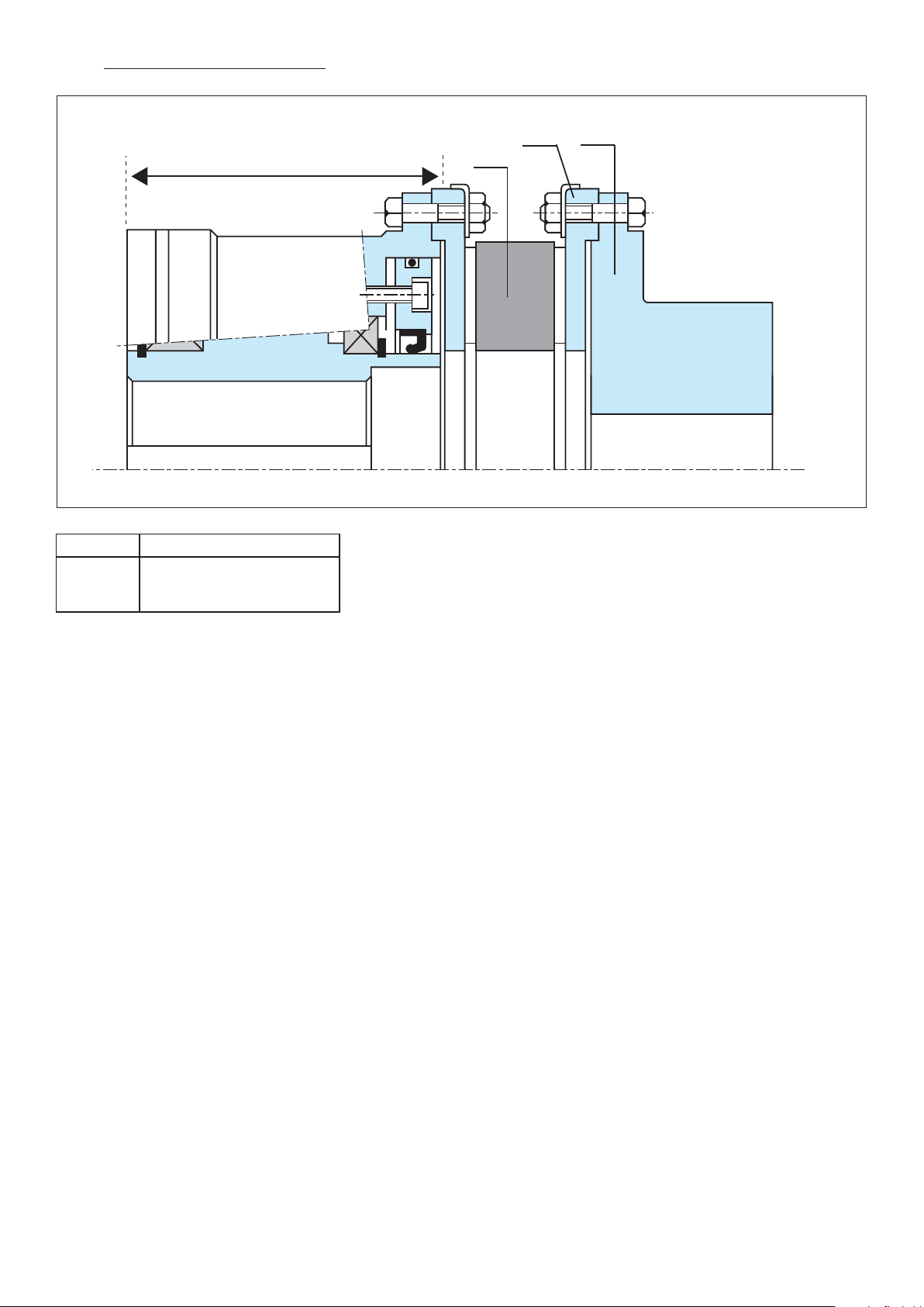
5.2 Drawings / Description VAR05
Ref. Nr Description
507
528
730
Coupling Hub
Coupling Flange
Spider
L 331 VAR 00
730
528
507
Subject to alteration without prior notice
6 Warner Electric Europe • +33 (0)2 41 21 24 24 P-2073-WE • 11/12
Page 7

NOTES
Warner Electric Europe • +33 (0)2 41 21 24 24 P-2073-WE • 11/12 7
Page 8

Warranty
Warner Electric LLC warrants that it will repair or replace (whichever it deems advisable) any product manufactured and
sold by it which proves to be defective in material or workmanship within a period of one (1) year from the date of original
purchase for consumer, commercial or industrial use.
This warranty extends only to the original purchaser and is not transferable or assignable without Warner Electric LLC’s
prior consent.
Warranty service can be obtained in the U.S.A. by returning any defective product, transportation charges prepaid, to
the appropriate Warner Electric LLC factory. Additional warranty information may be obtained by writing the Customer
Satisfaction Department, Warner Electric LLC, 449 Gardner Street, South Beloit, Illinois 61080, or by calling 815-389-
3771.
A purchase receipt or other proof of original purchase will be required before warranty service is rendered. If found
defective under the terms of this warranty, repair or replacement will be made, without charge, together with a refund for
transportation costs. If found not to be defective, you will be notified and, with your consent, the item will be repaired or
replaced and returned to you at your expense.
This warranty covers normal use and does not cover damage or defect which results from alteration, accident, neglect, or
improper installation, operation, or maintenance.
Some states do not allow limitation on how long an implied warranty lasts, so the above limitation may not apply to you.
Warner Electric LLC’s obligation under this warranty is limited to the repair or replacement of the defective product and
in no event shall Warner Electric LLC be liable for consequential, indirect, or incidental damages of any kind incurred by
reason of the manufacture, sale or use of any defective product. Warner Electric LLC neither assumes nor authorizes any
other person to give any other warranty or to assume any other obligation or liability on its behalf.
WITH RESPECT TO CONSUMER USE OF THE PRODUCT, ANY IMPLIED WARRANTIES WHICH THE CONSUMER MAY
HAVE ARE LIMITED IN DURATION TO ONE YEAR FROM THE DATE OF ORIGINAL CONSUMER PURCHASE. WITH
RESPECT TO COMMERCIAL AND INDUSTRIAL USES OF THE PRODUCT, THE FOREGOING WARRANTY IS IN LIEU
OF AND EXCLUDES ALL OTHER WARRANTIES, WHETHER EXPRESSED OR IMPLIED BY OPERATION OF LAW OR
OTHERWISE, INCLUDING, BUT NOT LIMITED TO, ANY IMPLIED WARRANTIES OF MERCHANTABILITY OR FITNESS.
Some states do not allow the exclusion or limitation of incidental or consequential damages, so the above limitation or
exclusion may not apply to you. This warranty gives you specific legal rights and you may also have other rights which
vary from state to state.
Changes in Dimensions and Specications
All dimensions and specifications shown in Warner Electric catalogs are subject to change without notice. Weights do not
include weight of boxing for shipment. Certified prints will be furnished without charge on request to Warner Electric.
Warner Electric Europe
7 rue Champfleur, B.P. 20095, St Barthelemy d’Anjou - France
+33 (0)2 41 21 24 24 • Fax: +33 (0)2 41 21 24 70
www.warnerelectric.com
Printed in USAP-2073-WE • 11/12
 Loading...