

Page 1
P-2081-WE
SM302gb - rev 02/09
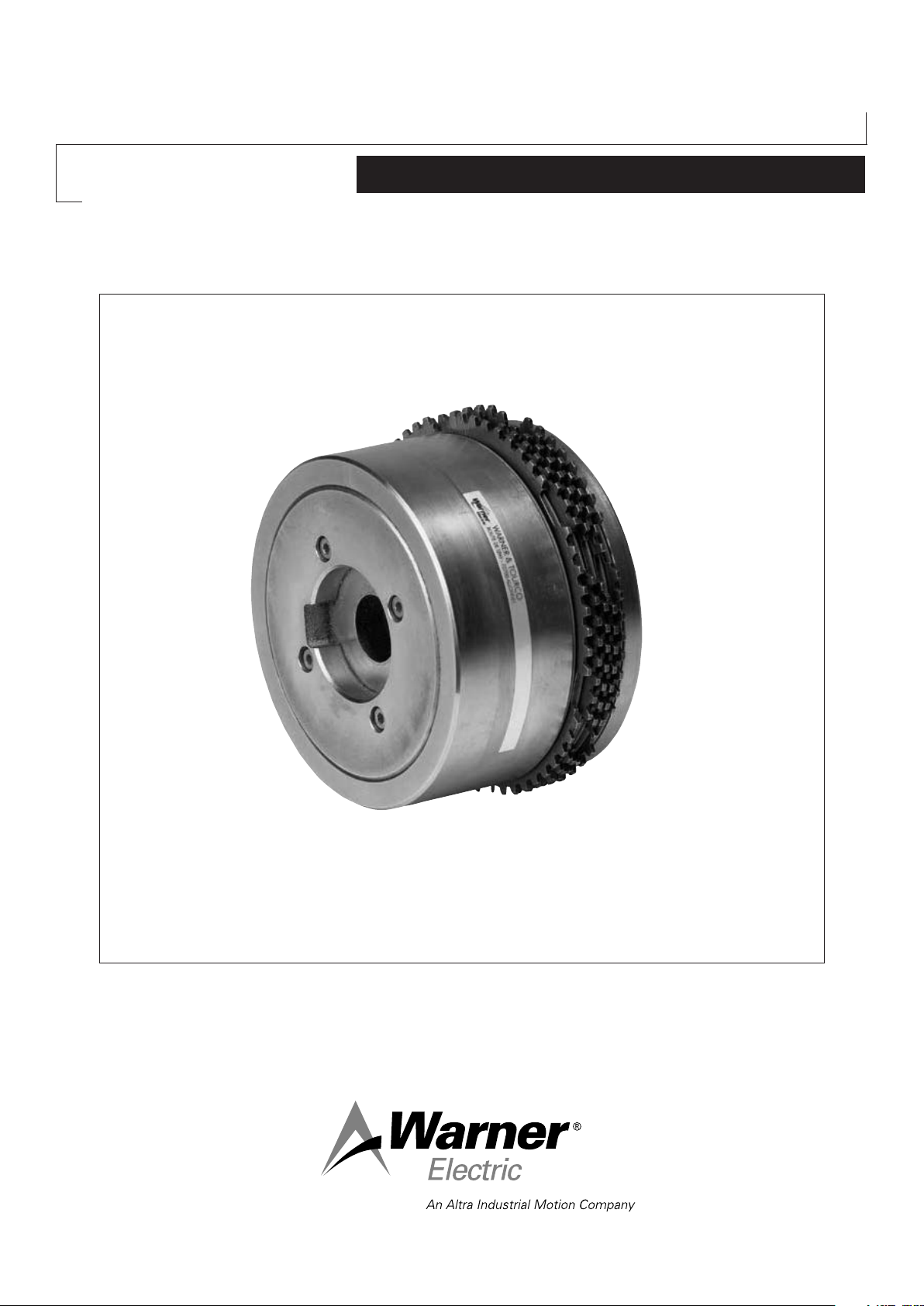
Pneumatic Multidisc Clutch
P 130 VAR00 / VAR02
Service Manual
Page 2

We, WARNER ELECTRIC EUROPE, 7, rue Champfleur, B.P. 20095, F-49182 St Barthélemy d’Anjou Cedex
declare that clutches made in our factory from St Barthélemy d’Anjou,
and hereafter designated : P 130 VAR00/VAR02
are designed to be incorporated into an
installation or assembled with other equipment
in order to form a machine that is covered by
directive 98/37/EC.
St Barthélemy d’Anjou, July 2002
Eric Prat, General Managing Director
CONTENTS
1 Technical specifications 2
2 Precautions and restrictions on use 2
2.1 Restrictions on use 2
2.2 Precautions 3
and safety measures
3 Installation 3
3.1 Transport - storage 3
3.2 Handling 3
3.3 Setting up 3
4 Maintenance 3
1 Technical Specifications
4.2 Spare Parts 4
4.3 Dismantling / Reassembling 4
5 Pneumatic connection 4
5.1 Important recommendations 4
5.2 Connection diagrams 5
6 Appendix 5
6. 1 Drawings / Description 5
7. Troubleshooting 5
Symbol designating
an action that might
damage the brake
Symbol designating an
action that might be
dan gerous to human safety
Symbol designating an
elec trical action that might be
dangerous to human safety
2 Precautions and restrictions on use
2.1 Restrictions on use
These clutches are designed solely to run
These clutches are designed to run dry. Any oily
material alters their performance.
on a horizontal shaft. Ask our technical
department about other positions.
Exceeding the maximum rotation speed given in
the catalogue invalidates the warranty.
2 Warner Electric Europe • +33 (0)2 41 21 24 24 P-2081-WE • 2/13
Page 3

2.2 Precautions and safety measures
During the maintenance period make sure
that the moving parts of the machine are
stationary and that there is no risk of start-up.
All intervention have to be made by qualified
personnel, owning this manual.
In cases where two coaxial shafts are fitted, the
maximum authorised setover is 0,05 mm. The
angular misalignment should not exceed 0,1
mm over a length of 100 mm. If these values
cannot be attained, we recommend that an
elastic coupling is fitted between the drive and
receiving parts.
Any modification made to the brake without
the express authorisation of a representative of
Warner Electric, in the same way than any use
out of the contrac tual specifications accepted
by “Warner Electric”, will result in the warranty
being invalidated and Warner Electric will
no longer be liable in any way with regard to
conformity.
3 Installation
3.1 Transport / storage
These units are supplied as standard in
packaging guaranteeing protection for a period
of 6 months by land or air transport, or after
transport by ship to neighbouring continents
(without crossing the tropics).
3.2 Handling
The clutch is supplied pre-assembled with the
driving flange not fixed.
Avoid any impact on the units so not to alter
their performance.
3.3 Mise en place
The hub (515) is normally supplied at tolerances
H7 for the bote and P9 for the width of the
keyway (In accordance with NF E 22-175/DIN
6885/BS 4235/ISO R773).
Do not forget to secure the bolts fixing the
driving flange (529) with Loctite 243 or an
equivalent type of product and tighten them to
torque.
Never directly strike the cylinder (401), closing
flange (408), or hub (515), use a soft alloy block
or drift between these parts and the fitting
device provided.
It is essential to comply with the length
dimension “ L ± 0,5 “ (see table 1) in order to
prevent any risk of contact between the drive
flange (529) and the hub (515).
4 Maintenance
4.1 Maintenance
P130, VAR00/02 series clutches only require low
maintenance because wear in the disc set is
automatically compensated for by movement in
the piston, within the limits of its travel.
It is however necessary to:
• Regularly check the seal of the pressure
chamber and in the event of leakage, or after 5
years use, change the seals (701, 702)
• Check the wear on the disc set, by measuring
the travel of the piston (402), using table 2,
below and the diagrams on annex
The drive flange (529) is generally supplied at a
bore H7 but without fixing holes.
We recommend a tolerance h6 for the shaft and
an adjustment H7/f7 for he drive flange (529).
• Centre the flange (529) on the recieving part,
then fix it with bolts and lock them
• Slide the hub (515) onto the shaft (after
adjusting the keyways) by positioning the teeth
of the outer discs (302) or (305), opposite of the
hollows of the driving flange (529).
Warner Electric Europe • +33 (0)2 41 21 24 24 P-2081-WE • 2/13 3
Page 4

4.2 Spare Parts
5 Pneumatic Connections
All orders for spare parts must state the size
of the unit with its code number, the reference
number of the part (see appendice 1), and the
quantity of each component wanted.
4.3 Dismantling / Reassembling
During maintenance work, ensure that the
mechanism to be driven by the clutch is at
rest and that there is no risk of it being started
accidentally. Also ensure that the compressed
air is turned off.
Dismantling:
• Remove the fixing screws from the cylinder
(401) or closing flange (408)
• Remove the cylinder (401) or closing flange
(408)
• Take out the piston (402)
• Remove the worn disc set
• Fit a new disc set
Start with an outer disc (302 or 305), then an
inner disc (308), and then alternate, ending of
necessity with an outer disc.
• Change the seals (701, 702)
• Refit the piston (402)
• Refit the cylinder (401) or closing flange (408)
Take care not to damage the seals while
reassembling
• Replace the cylinder (401) or closing flange
(408 fixing screws, tighten them to the torque
shown in table 3, below and secure them with
Loctite 243 or an equivalent type of product
5.1 Important Recommendations
Ensure that working pressures are complied
with, to get the nominal performance from the
equipment.
Do not exceed the maximum pressures
(see table 1).
These clutches should be supplied with filtered,
oiled air.
5.1 Connection Diagram
The diagrams are only given as an indication.
Fig 1: Basic circuit for circuit under pressure
a: source of pressure
b: air treatment unit
c: distributor
d: flexi pipe and rotating seal
e: clutch engagement by application of pressure
4 Warner Electric Europe • +33 (0)2 41 21 24 24 P-2081-WE • 2/13
Page 5

6 Appendix
6.1 Drawings / Description
7 Troubleshooting
Warner Electric Europe • +33 (0)2 41 21 24 24 P-2081-WE • 2/13 5
Page 6

Warranty
Warner Electric LLC warrants that it will repair or replace (whichever it deems advisable) any product manufactured and
sold by it which proves to be defective in material or workmanship within a period of one (1) year from the date of original
purchase for consumer, commercial or industrial use.
This warranty extends only to the original purchaser and is not transferable or assignable without Warner Electric LLC’s
prior consent.
Warranty service can be obtained in the U.S.A. by returning any defective product, transportation charges prepaid, to
the appropriate Warner Electric LLC factory. Additional warranty information may be obtained by writing the Customer
Satisfaction Department, Warner Electric LLC, 449 Gardner Street, South Beloit, Illinois 61080, or by calling 815-389-
3771.
A purchase receipt or other proof of original purchase will be required before warranty service is rendered. If found
defective under the terms of this warranty, repair or replacement will be made, without charge, together with a refund for
transportation costs. If found not to be defective, you will be notified and, with your consent, the item will be repaired or
replaced and returned to you at your expense.
This warranty covers normal use and does not cover damage or defect which results from alteration, accident, neglect, or
improper installation, operation, or maintenance.
Some states do not allow limitation on how long an implied warranty lasts, so the above limitation may not apply to you.
Warner Electric LLC’s obligation under this warranty is limited to the repair or replacement of the defective product and
in no event shall Warner Electric LLC be liable for consequential, indirect, or incidental damages of any kind incurred by
reason of the manufacture, sale or use of any defective product. Warner Electric LLC neither assumes nor authorizes any
other person to give any other warranty or to assume any other obligation or liability on its behalf.
WITH RESPECT TO CONSUMER USE OF THE PRODUCT, ANY IMPLIED WARRANTIES WHICH THE CONSUMER MAY
HAVE ARE LIMITED IN DURATION TO ONE YEAR FROM THE DATE OF ORIGINAL CONSUMER PURCHASE. WITH
RESPECT TO COMMERCIAL AND INDUSTRIAL USES OF THE PRODUCT, THE FOREGOING WARRANTY IS IN LIEU
OF AND EXCLUDES ALL OTHER WARRANTIES, WHETHER EXPRESSED OR IMPLIED BY OPERATION OF LAW OR
OTHERWISE, INCLUDING, BUT NOT LIMITED TO, ANY IMPLIED WARRANTIES OF MERCHANTABILITY OR FITNESS.
Some states do not allow the exclusion or limitation of incidental or consequential damages, so the above limitation or
exclusion may not apply to you. This warranty gives you specific legal rights and you may also have other rights which
vary from state to state.
Changes in Dimensions and Specications
All dimensions and specifications shown in Warner Electric catalogs are subject to change without notice. Weights do not
include weight of boxing for shipment. Certified prints will be furnished without charge on request to Warner Electric.
Warner Electric Europe
7 rue Champfleur, B.P. 20095, St Barthelemy d’Anjou - France
+33 (0)2 41 21 24 24 • Fax: +33 (0)2 41 21 24 70
www.warnerelectric.com
Printed in USAP-2081-WE • 2/13
 Loading...