

Page 1

UNIBRAKE
Warner Electric
®
Motor Brakes
P-1699-WE
Installation & Operating Instructions
Rear Mounted
Double “C” Coupler
Page 2
Contents
Operation
General Information. . . . . . . . . . . . . . . . . . . . . . . . 2
Brake Heads . . . . . . . . . . . . . . . . . . . . . . . . . . . . . 2
Installation . . . . . . . . . . . . . . . . . . . . . . . . . . . . . . . 3
Wiring . . . . . . . . . . . . . . . . . . . . . . . . . . . . . . . . . . 4
Wear Adjustments. . . . . . . . . . . . . . . . . . . . . . . . . 4
Torque Adjustments . . . . . . . . . . . . . . . . . . . . . . . 5
Disc Replacement . . . . . . . . . . . . . . . . . . . . . . . . . 5
Coil Replacement . . . . . . . . . . . . . . . . . . . . . . . . . 5
Service Parts . . . . . . . . . . . . . . . . . . . . . . . . . . . . . 6
Warranty. . . . . . . . . . . . . . . . . . . . . . . . . Back Page
General Information
Motor Brakes are not a fail safe
device. Where holding load represents a risk of
property damage, and/or personal injury, an
independent fail safe device must be supplied
independent of this brake. These safety
devices are neither provided nor are they the
responsibility of Warner Electric.
When properly connected, starting the motor
energizes the brake magnet coil, attracting the
armature to the coil, compressing the torque
springs, releasing pressure on the stationary
plates, permitting the brake discs to rotate freely.
When the motor and the brake magnet coil
de-energize, this decompresses the torque
springs, forcing the rotating disc(s) and stationary
pressure plates together, stopping and holding the
motor shaft and load.
When the motor is ‘off,’ to move the driven load
without energizing the motor, rotating the manual
release lever 90 degrees clockwise removes the
retarding torque from the motor shaft letting the
load be hand-moved. The lever returns to the
normal “set” position when the brake is
re-energized.
Brake Heads
Warner Electric Unibrake motor brakes are spring
set, electro-magnetic release, direct acting, disc
brakes for the controlled stopping and holding of a
load. They have single phase electro-magnetic
coils in standard voltages and frequencies and are
factory set for rated retarding torque.
Rear Mounted
Construction
Unibrakes utilize one or more non-asbestos
friction discs mounted on a metal hub which is
fastened to a rotating shaft. The brake uses a two
ball pivot design for its armature plate. It also has
a self resetting manual release lever. Anti-rattle clip
between the rotating disc and hub help reduce
torsional vibration and pulsation noise. Rear
mounted Unibrakes are available in standard
aluminum or cast iron housed constructions and
the double NEMA “C” Face coupler in aluminum
only.
Warner Electric • 800-825-9050 P-1699-WE
2
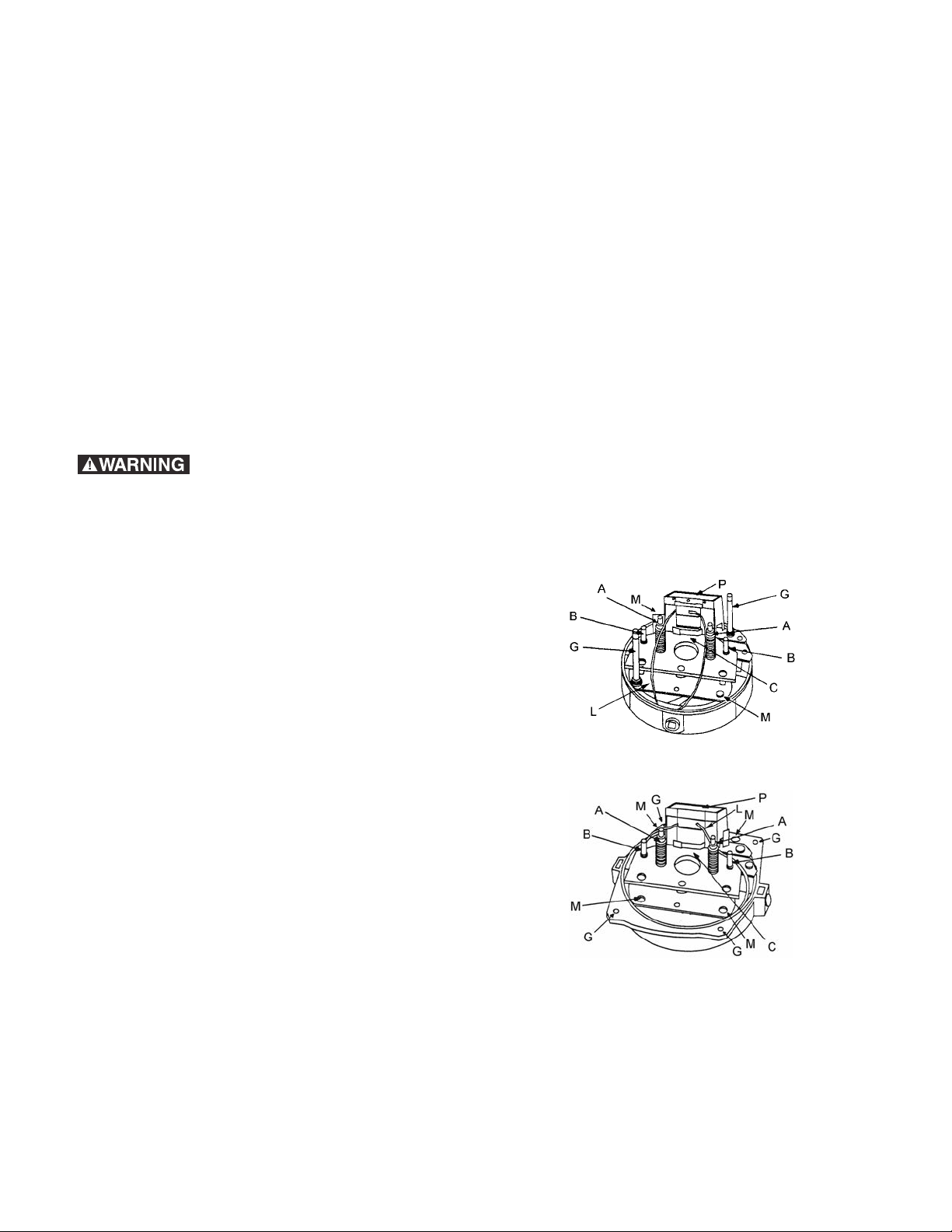
A = Torque Adjust Nuts and Springs
B = Wear Adjustment Screws
C = Armature Plate
G = Cover Mounting (2) Studs Rear Mounted, (4)
Bolts/Nuts Coupler
L = Lead Wires
M = Mounting Holes (2 rear mounted, 4 coupler)
P = Solenoid (coil)
Double “C” Face Coupler
Page 3
Any mechanism or load held in
Customers
Motor
5/16 inch
Hub
Key
Motor
Output
Shaft
End
Customers
Motor
Hub
Key
Motor
Output
Shaft
End
1/2 inch
position by the brake should be checked to
avoid possible damage or injury to personnel
before brake is released manually.
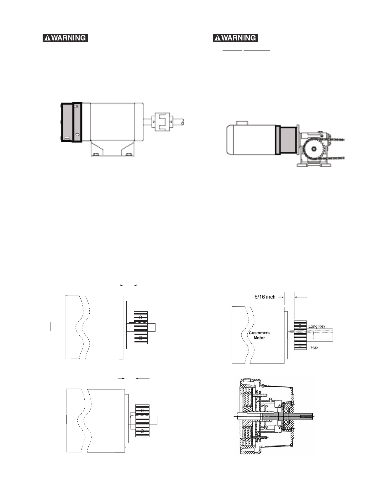
Installation
Rear Mounted
Coupler style output shaft must
be direct
coupled to load not for belted or any
type overhung load applications.
Remove (4) hex screws and lift off cover/shaft
assembly. Remove brake hub and attach it to the
motor shaft using the long key and set screws.
Locate hub 5/16 inch away from mounting face of
motor as shown below. Tighten setscrews to 55-
Coupler
Remove cover from brake, locate brake hub. Attach hub to shaft using key and set screw
provided. Position hub from mounting face of motor
as shown for your type of brake head. Tighten set
screws to 55-100 in. lbs. of torque. Slip brake head
body onto mounting face and fasten with (2) 3/8
inch socket head cap screws. Cover will be assembled after brake is wired. Leads should be twisted
and inserted into the insulation sleeve and routed
to conduit port or openings through back of motor.
Aluminum Brake Head
100 in. lbs. of torque. Slip brake head assembly
over brake hub and onto the motor mounting face.
Fasten with (4) 3/8-16 socket head cap screws.
Leads should be twisted and routed across top
front of coil away from rotating brake hub and then
routed through lead clip on side of coil. Replace
brake cover/shaft assembly after wiring by
inserting keyed shaft into the brake hub extension
and guiding cover over the brake head assembly,
the center window should be located over brake
release lever to allow for gap inspection. Secure
with (4) hex bolts and nuts.
Rear
Mounted
Coupler
Cast Iron Brake Head
Warner Electric • 800-825-9050 P-1699-WE
3
Page 4

Wiring
Disconnect power before
touching any internal part.
Unibrake magnet coils (AC) are single phase and
dual voltage. These can be wired internal to the
motor. Direct current brake coils must be
separately operated; switch contacts to control the
brake must be different from those used to control
the motor. Normally, motor and brake
contacts must be interlocked.
Determine the voltage of the brake and use the
appropriate wiring instructions below.
Brake Leads (B) to Motor Leads (T)
Motor Voltage or Separate Power Supply
3 Phase AC
1 Phase AC
Separately AC
Separately DC 24 or 90 VDC
Low Voltage B1 & B3 to T1 & T7 B2 & B4 to T2 & T8
High Voltage B1 to T1 B2 to B3 B4 to T2
Low Voltage B1 & B3 to T1 & T3 B2 & B4 to T2 & T4
High Voltage B1 to T1 B2 to B3 B4 to T4
Low Voltage B1 & B3 to Line 1 (L1) B2 & B4 to Line 2 (L2)
High Voltage B1 to Line 1 (L1) B2 to B3 B4 to Line 2 (L2)
B1 to DC + B2 to DC -
Coils are not polarity sensitive
connections can be reversed.
Wear Adjustments
1) Disconnect power brake before
touching any internal part. 2) Any loads that are
held in position by this brake must be
supported before performing any adjustments
or maintenance.
Gap Chart
No. of Discs Gap “G”
1 .075 inch
2 or 3 .090 inch
Rear Mounted
Remove cover; turn both screws “B” equal
amounts in a clockwise direction until air gap (Gap
“G”) from above chart is obtained. Measurement
of air gap should be made at approximate center
of magnet with pressure applied to armature plate
“C” to assure plate is seated on pivot balls. Failure
to adjust for wear will result in eventual loss of
braking torque.
Note: Unequal adjustment of screws “B” will result
in unequal pivot action on balls that will increase
noise and shorten brake life.
Unibrake discs require periodic adjustment due to
expected wear. On rapid cycling applications
regular inspections should take place, i.e. after
20,000 to 50,000 cycles for the first inspection and
then every 150,000 to 200,000 cycles. Adjustments
should be made to the air gap between the
armature and magnet for continued brake
effectiveness. If an increase in stopping time is
noted adjust brake as follows:
Coupler
Remove the 3 window covers, turn both screws
“B” equal amounts in a clockwise direction until air
gap (Gap “G”) from above chart is obtained.
Measurement of air gap should be made at
approximate center of magnet with pressure
applied to armature plate “C” to assure plate is
seated on pivot balls. Failure to adjust for wear will
result in eventual loss of braking torque.
Note: Unequal adjustment of screws (B) will result
in unequal pivot action on balls that will increase
noise and shorten brake life.
Warner Electric • 800-825-9050 P-1699-WE
4
Page 5

Torque Adjustments
Rear Mounted Coupler
Most applications do not require torque
adjustments. Unibrakes
are factory set for rated
torque which is maximum
torque. To increase
stopping time or reduce
torque on 3, 6, and 10 ft.
lb., turn 2 lock nuts “A” an
equal amount counterclockwise to increase
spring length. For the 6,
10, and 15 ft. lb. brakes,
one full turn will reduce
torque by about 12-1/2%.
The 3 ft. lb. brake will be
reduced in torque by about 8%. Torque should not
be reduced by less than 1/2 of the rated torque.
If torque is adjusted, measure air gap (see wear
adjustment) and verify it is within dimensions from
Gap Chart.
1) Disconnect power brake
before touching any internal part. 2) Any loads
that are held in position by this brake must be
supported before performing any adjustments
or maintenance.
Friction Disc Replacement
Rear Mounted
Remove cover, (2) cover support studs “G”, and (2)
3/8-16 mounting cap screws at “M”.
Lift off brake mechanism assembly. Remove
pressure plate(s) and brake disc(s). Replace with
new pressure plate(s) and disc(s). Reassemble
brake mechanism assembly. Multiple disc units,
the domed pressure plate is positioned furthest
away from the motor or brake head; the (B) wear
adjustment screws are in contact with this plate.
Note: Cast Iron Heads: Last disc uses the cast
housing as a friction surface. Set air gap for wear
adjustment.
Coupler
Remove (4) hex head screws that hold the
cover/shaft assembly to the brake head. Remove
the (4) 3/8-16 mounting cap screws at “M.”
Remove (2) 1/4-20 round head screws and lift off
brake mechanism assembly. Remove pressure
plate(s) and brake disc(s). Replace with new
pressure plate(s) and disc(s). Reassemble brake
mechanism assembly. Multiple disc units, the
domed pressure plate is positioned furthest away
from the motor or brake head; the (B) wear
adjustment screws are in contact with this plate.
Set air gap for wear adjustment.
Magnetic Coil Replacement
Rear Mounted
Remove cover, (1) cover support stud “G”, (1)
3/8-16 mounting cap screw “M” and (2) slotted
screws “E”.
Warner Electric • 800-825-9050 P-1699-WE
5
Page 6

Lift off complete coil assembly “P” and replace
with new coil assembly of proper electrical rating.
Position leads so as to avoid contact with rotating
parts. Set air gap for wear adjustment.
Coupler
Remove (4) hex head screws that hold the
cover/shaft assembly to the brake head. Remove
(2) 3/8-16 mounting cap screws at “M”. and (2)
slotted screws ”E”. Lift off complete coil assembly
“P” and replace with new coil assembly of the
proper electrical rating. Position leads so as to
avoid contact with rotating parts. Set air gap for
wear adjustment. Replace cover/shaft assembly
per installation instructions.
Service Parts
Disc/Pressure Plate Kits
Number Kit Kit
Discs Number Contents
Aluminum Heads
1 327212-1 1FD, 1DPP and 1FPP
2 327212-2 2FD, 1DPP and 2FPP
3 327212-3 3FD, 1DPP and 3FPP
Cast Iron Heads
1 327212-4 1FD and 1DPP
2 327212-5 2FD, 1DPP and 1 FPP
3 327212-6 3FD, 1DPP and 2FPP
FD = Friction Disc, DPP = Domed Plate FPP = Flat Plate
1 327213 Disc with Anti-rattle clip
Friction Disc Onl
y
Rear Mounted Hubs
Bore Hub Number
5/8 58D23
3/4 58D23
7/8 58D24
Hub
Coil Assembly (Solenoids)
Unibrake magnet coils (AC) are single phase.
Coil Voltage Coil Part No. DC Resistance*
60/115/230 VAC 79137-18-K
50/115/230 VAC 79137-18-N
50/220/440 VAC 79137-18-P
60/230/460 VAC 79137-18-J
60/200/400 VAC 79137-18-L
60/287/575 VAC 79137-18-G
50/208/416 VAC 79137-18-M
24 VDC 327208 Leads B1 to B2 = 26.4 Ohms
90 VDC 327209 Leads B1 to B2 = 390 Ohms
Leads B1 to B2 or
B3 to B4 = 8.7 Ohms
Leads B1 to B2 or
B3 to B4 = 11.5 Ohms
Leads B1 to B2 or
B3 to B4 = 43.5 Ohms
Leads B1 to B2 or
B3 to B4 = 34.5 Ohms
Leads B1 to B2 or
B3 to B4 = 24.3 Ohms
Leads B1 to B2 or
B3 to B4 = 54.5 Ohms
Leads B1 to B2 or
B3 to B4 =35.6 Ohms
*Resistance values plus or minus 10% at 25°C
Friction Disc (FD)
5 inch diameter
Pressure Plates
Domed (DPP) / Flat (FPP)
Coil Assembly
Warner Electric • 800-825-9050 P-1699-WE
6
Page 7

Page 8

Warranty
Warner Electric LLC warrants that it will repair or replace (whichever it deems advisable) any
product manufactured and sold by it which proves to be defective in material or workmanship
within a period of one (1) year from the date of original purchase for consumer, commercial or
industrial use.
This warranty extends only to the original purchaser and is not transferable or assignable without
Warner Electric LLC’s prior consent.
Warranty service can be obtained in the U.S.A. by returning any defective product, transportation
charges prepaid, to the appropriate Warner Electric LLC factory. Additional warranty information
may be obtained by writing the Customer Satisfaction Department, Warner Electric LLC, 449
Gardner Street, South Beloit, Illinois 61080, or by calling 815-389-3771.
A purchase receipt or other proof of original purchase will be required before warranty service is
rendered. If found defective under the terms of this warranty, repair or replacement will be made,
without charge, together with a refund for transportation costs. If found not to be defective, you will
be notified and, with your consent, the item will be repaired or replaced and returned to you at
your expense.
This warranty covers normal use and does not cover damage or defect which results from
alteration, accident, neglect, or improper installation, operation, or maintenance.
Some states do not allow limitation on how long an implied warranty lasts, so the above limitation
may not apply to you.
Warner Electric LLC’s obligation under this warranty is limited to the repair or replacement of the
defective product and in no event shall Warner Electric LLC be liable for consequential, indirect,
or incidental damages of any kind incurred by reason of the manufacture, sale or use of any
defective product. Warner Electric LLC neither assumes nor authorizes any other person to give
any other warranty or to assume any other obligation or liability on its behalf.
WITH RESPECT TO CONSUMER USE OF THE PRODUCT, ANY IMPLIED WARRANTIES WHICH
THE CONSUMER MAY HAVE ARE LIMITED IN DURATION TO ONE YEAR FROM THE DATE OF
ORIGINAL CONSUMER PURCHASE. WITH RESPECT TO COMMERCIAL AND INDUSTRIAL
USES OF THE PRODUCT, THE FOREGOING WARRANTY IS IN LIEU OF AND EXCLUDES ALL
OTHER WARRANTIES, WHETHER EXPRESSED OR IMPLIED BY OPERATION OF LAW OR
OTHERWISE, INCLUDING, BUT NOT LIMITED TO, ANY IMPLIED WARRANTIES OF
MERCHANTABILITY OR FITNESS.
Some states do not allow the exclusion or limitation of incidental or consequential damages, so the
above limitation or exclusion may not apply to you. This warranty gives you specific legal rights and
you may also have other rights which vary from state to state.
Changes in Dimensions and Specifications
All dimensions and specifications shown in Warner Electric catalogs are subject to change without
notice. Weights do not include weight of boxing for shipment. Certified prints will be furnished
without charge on request to Warner Electric.
Warner Electric LLC
31 Industrial Park Road • New Hartford, CT 06057
815-389-3771 • Fax: 815-389-2582
www.warnerelectric.com
An Altra Industrial Motion Company
P-1699-WE 6/11 Printed in USA
 Loading...