

Page 1
Gen 2
Ceramic Faced Clutch/Brake UniModule
UM-50C, UM-180C
P-273-10
819-0532
Installation Instructions
An Altra Industrial Motion Company
Page 2
Contents
Mounting to a C-Face Motor . . . . . . . .3
Mounting to a Reducer . . . . . . . . . . . . .4
Installing the Base Mount . . . . . . . . . . .4
Installing the Motor Mount Bracket . . .5
Mounting to Other Power
Transmission Components . . . . . . . .5
Electrical Connections . . . . . . . . . . . . . .6
Troubleshooting-Electrical . . . . . . . . . . .6
Troubleshooting-Mechanical . . . . . . . . .6
Warranty . . . . . . . . . . . . . . . . . . . . . . .BC
Failure to follow these
instructions may result in product damage,
equipment damage, and serious or fatal
injury to personnel.
The equipment covered by
this installation manual must be installed in
accordance with these instructions. Failure
to do so may damage the equipment and
void the warranty.
The ceramic versions of Warner Electric
UniModules are completely assembled
clutch/brake packages for out of box use.
They are engineered for easy installation, while
providing extra long life over standard units.
Technically advanced ceramic friction material
provides exceptional wear resistance and
enhanced performance making Ceramic
UniModule clutch/brakes ideal for high cycle
rate applications.
Ceramic clutch/brake combinations are offered
in two configurations. The "1020-C" has a hub
input and a male shaft output. The "2030-C" has
a male shaft extension for both input and output. These two configurations are offered with
various mounting accessories to make ceramic
friction faced UniModules adaptable to many
power transmission systems.
The 1020-C UniModules are designed to mount
to the face of a C-Face motor as noted in
Table 1.
Corresponding
NEMA Frame Sizes
C-Face
UM Old New Shaft Pilot
Size NEMA NEMA Dia. Dia.
50 56 C 48 Y 5/8" 4-1/2"
180 182 C 143 TC 7/8" 4-1/2"
184 C 145 TC
Table 1
The 2030-C UniModules are designed to mount
using a base mounting kit. This allows the
modules to be mounted as a separate drive unit
driven from the prime mover by V-belts, chain
and sprockets, couplings, timing belts and other
standard power transmission components.
(For UniModule size 210-C please refer to
Warner Electric manual P-273-3)
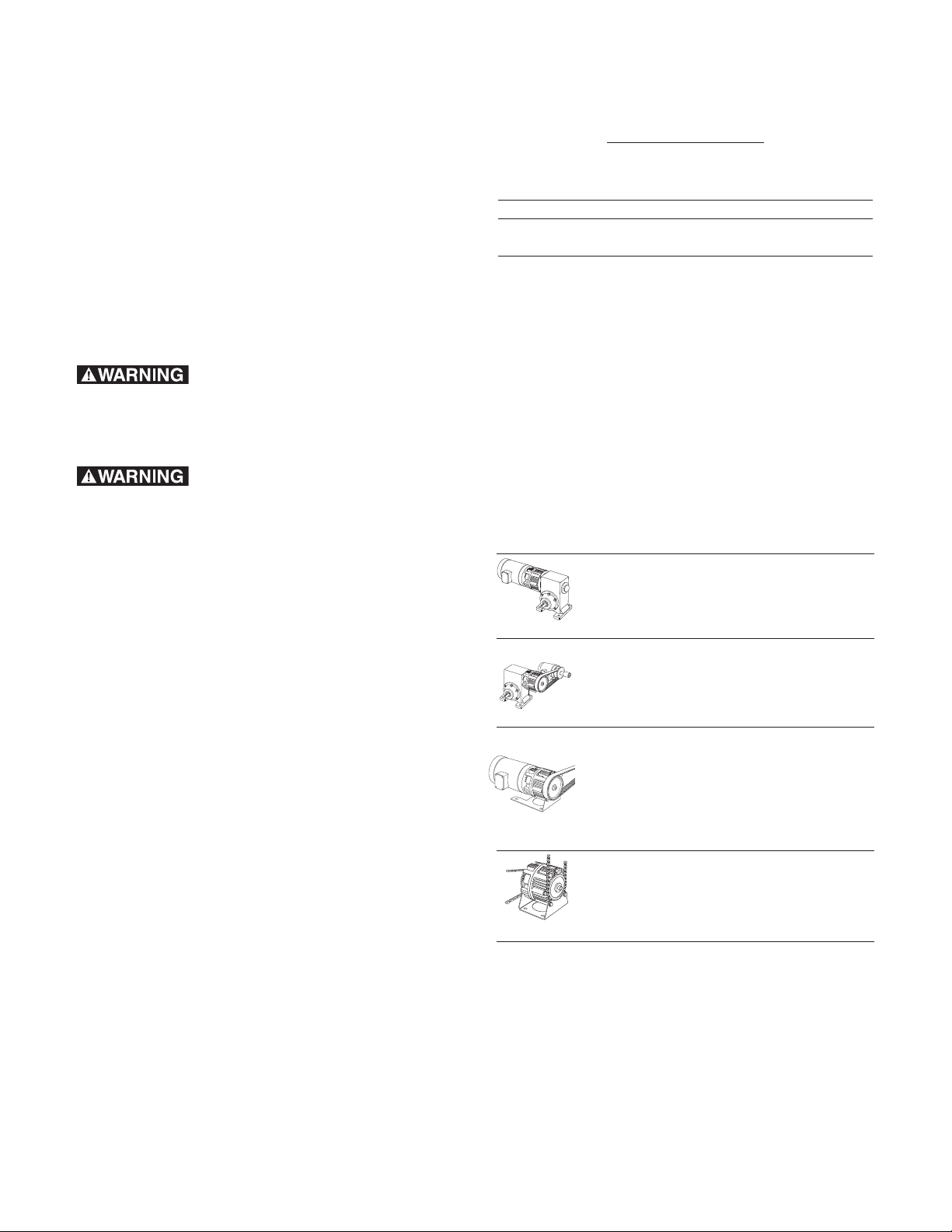
For These UM-C Combinations Use These
UniModule Clutch/Brake between
C-Face Motor and Reducer
1020-C
UniModule Clutch/Brake
2030-C
Motor Mount Module Clutch/Brake
on a C-Face Motor
1020-C-M
Base Mounted
UniModule Clutch/Brake
2030-C-B
Installation Steps:
Mounting to a Motor
Mounting to a Reducer
Electrical Connections
Mounting to other
Power Transmission
Components
Electrical Connections
Mounting to a Motor
Installing the Motor
Mount Bracket
Mounting to other
Power Transmission
Components
Electrical Connections
Installing the Base Mount
Mounting to other
Power Transmission
Components
Electrical Connections
Install your specific Ceramic UniModule
combination according to the installation steps
specified in the table. Use only those steps
indicated for each combination.
Warner Electric • 800-825-9050 P-273-10 • 819-0532
2
Page 3
Mounting to a C-Face Motor
1. A hardened key is provided with the
mounting hardware for Ceramic UniModules.
Insert this key onto the motor shaft. It is
recommended to stake the end of the
motor shaft keyway to keep the key from
moving out during operation.
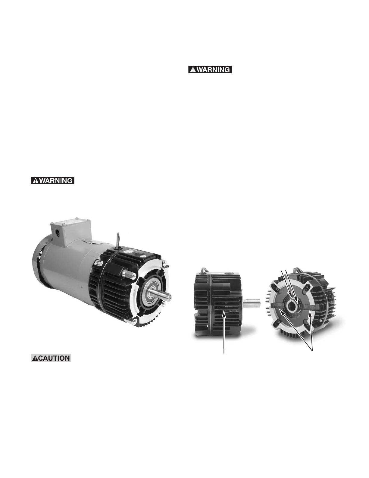
2. Align the keyway in the bore of the
UniModule to the key in the motor shaft
and slide the unit onto the motor shaft.
The normal alignment of the module to the
motor will be with the wire exit/conduit
box in the upright (12 o’clock) position as
shown in Figure 1.
Do not hammer or force the
module into position. To do so may damage
bearings or cause the friction faces to shift out
of alignment.
alternately to ensure even alignment of the
module. Tighten them to 30-35 foot
pounds.
Do not tighten the two (2) clutch
rotor set screws to the shaft before tightening
the four (4) module tie-bolts. This could cause
a preload on the pilot bearing resulting in
premature bearing failure.
4. Next secure the clutch rotor and fan
assembly to the motor shaft by tightening
the two (2) setscrews as follows:
a. There are two (2) access slots on
either side of the UniModule. A long
Allen wrench can be used to tighten
the two setscrews (90° apart) which
secure the clutch rotor and fan
assembly to the motor shaft.
b. Alternately align each setscrew with
one of the access slots by rotating the
clutch rotor and fan assembly through
one of the side vents with a small
screw driver taking care not to damage
the fan. (Figure 2a)
Set Screws
Figure 1
If anti-fretting lubricant is used
on the motor shaft for future ease of removal,
Side Vent
Figure 2a
Access Slots
ensure that any excess is wiped off before unit
assembly to avoid lubricant contaminating the
clutch or brake friction faces.
c. Using a torque wrench and long Allen
socket, tighten the two (2) setscrews
to: (Figure 2b)
3. Secure the Ceramic UniModule to the motor
with the four (4) long mounting tie-bolts
provided. Tighten the four (4) bolts
• Size 50: 80-85 inch pounds
(Requires 5/32 inch Allen wrench)
• Size 180: 40-45 inch pounds
(Requires 1/8 inch Allen wrench)
Warner Electric • 800-825-9050 P-273-10 • 819-0532
3
Page 4
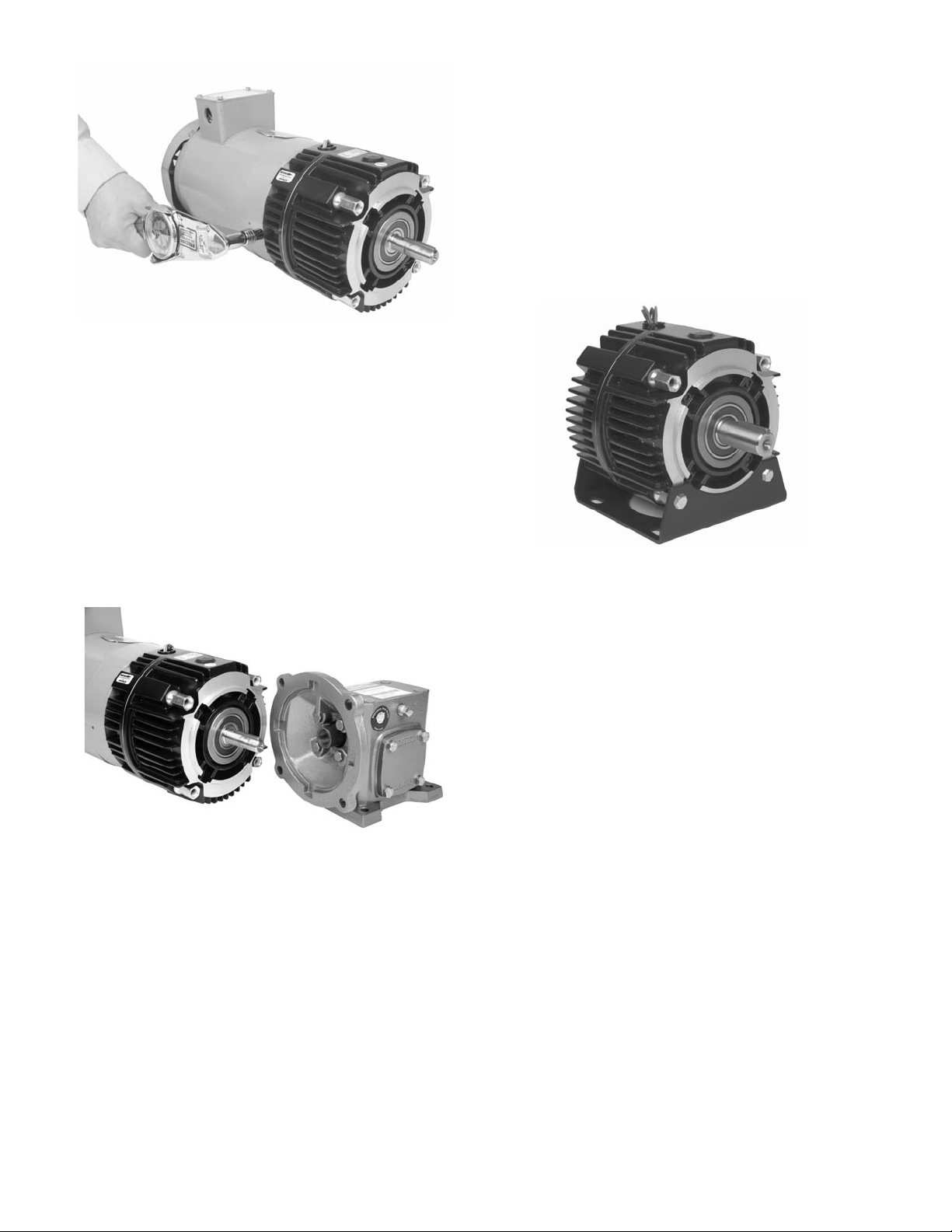
Figure 2b
Mounting to a Reducer
1. Warner Electric UniModules are furnished
with a hardened key pre-mounted on the
output shaft.
2. Align the output shaft and key of the
module with the corresponding bore and
keyway of the reducer. Slide the assembly
together as shown in Figure 3.
Installing the Base Mount
Model 2030-C UniModules are designed to be
base mounted as shown in Figure 4.
Optional Base Mount Kit,
Warner Electric part numbers:
UM-50..................................5370-101-004
UM-180................................5370-101-002
Figure 4
Figure 3
3. Bolt the module to the reducer flange.
The four (4) bolts that are required
(3/8-16UNC2A) are typically provided with
the reducer. Tighten to 18-22 foot pounds
of torque.
1. The pilot diameters on each end of the
UniModule will mate with the pilot
diameters on the base.
2. Secure the base to the UniModule with the
four (4) bolts provided. Tighten to 18 to 22
foot pounds.
Warner Electric • 800-825-9050 P-273-10 • 819-0532
4
Page 5

Installing the Motor Mount Bracket
A Motor Mount Bracket can be installed on the
output end of a 1020-C UniModule to provide a
foot mounting for the complete assembly of a
UniModule and C-face motor.
Optional Motor Mount Kit,
Warner Electric part numbers:
UM-50...................................5370-101-078
UM-180.................................5370-101-079
1. Mount the bracket to the face of the
UniModule underneath the UniModule
and motor as shown in Figure 5. A pilot
diameter on the UniModule mates with
a pilot diameter on the bracket.
onfirm that the belt or chain
C
ightness meets the maximum side load
t
capability of the UniModule shown in
Table 2.
Overhung Load Data
(Shaft Side Load)
Overhung load data is provided in this manual for
the design engineer concerned with a specific
problem in this area. The maximum allowable
overhung load which can be applied to the shaft
of a UniModule may be determined by the use of
the accompanying chart.
A
R
Figure 5
2. Secure the motor bracket in place with
four (4) short bolts and washers provided.
Tighten to 18 to 22 foot pounds.
Mounting to Other Power
Transmission Components
Couplings, pulleys, sprockets or similar power
transmission components can be mounted to the
input and output shafts of a UniModule.
When mounting a pulley or
sprocket, ensure that the key is fully engaged
within the device hub or bushing.
Warner Electric • 800-825-9050 P-273-10 • 819-0532
UniModule Housing Face Load Rating
UM-50 1" (Center of Shaft) 177
UM-180 1" (Center of Shaft) 192
Distance Load is
Applied from Maximum
"A" Inches "R" Lbs.
2" (End of Shaft) 123
3" 95
2" (End of Shaft) 134
3" 104
Table 2
5
Page 6

Electrical Connections
To avoid injury (or even death),
always make certain all power is off before
attempting to install or service this device or
any electrical equipment.
Warner Electric Ceramic UniModules are provided
with a conduit hole threaded for a standard 1/2
inch conduit connection. Both the clutch and
brake lead wires exit this opening. If a Conduit
Box is desired, Warner Electric Conduit Box Kit,
part number: 5370-101-042, can be purchased
separately. The Conduit Box provides two conduit
connection holes for standard 1/2 inch conduit
connectors.
Ceramic UniModule clutch/brakes operate on DC
voltage. Warner Electric offers a complete line of
electronic controls to meet the needs of almost
any clutch or clutch/brake application. Each
Warner Electric control will show the proper
wiring connections for its use.
Troubleshooting - Electrical
If a UniModule is not functioning properly it is best
to check for these problems before replacing it.
A standard Ceramic UniModule clutch/brake
requires DC power to function. If power is not
reaching the clutch or brake, the clutch or brake
will not engage.
A good practice to follow is to check for
power at the lead wires to the clutch or brake
using a voltmeter.
• If power is present in the proper voltage
and current (see Electrical Coil data), then
skip ahead to the Mechanical
Troubleshooting section.
• If power is not present, inspect the lead
wires for breaks or cuts.
If the wires are intact, the problem may be
•
ith the power supply or the switch.
w
• Using a voltmeter, check to see that proper
DC voltage is leaving the power supply
and that the switch is sending power to
the clutch or brake.
• If there is no power leaving the switch or
power supply, check the incoming AC power
to ensure that it is reaching the power supply.
• If there is proper DC voltage present at the
magnet leads, and the clutch or brake will not
engage, an ohmmeter check of the individual
magnet coils can be made with the power off
and the circuit open. (To be certain, disconnect
one lead to the magnet.) Compare resistance
to the chart below.
Electrical Coil Data
Clutch Brake Clutch Brake Clutch Brake
Voltage–D.C. 90 90 24 24 66
Resistance UM-50-C 452 452 31.8 28.8 1.86 1.86
(OHMS) UM-180-C 392 392 26.7 26.7 1.81 1.81
Current UM-50-C .199 .199 .755 .833 3.23 3.23
(Ampheres) UM-180-C .230 .230 .896 .896 3.31 3.31
Power UM-50-C 17.9 17.9 18.1 20.0 19.4 19.4
(WATTS) UM-180-C 20.7 20.7 21.5 21.5 20 20
Coil Build Up UM-50-C 52 53 52 53 52 53
Time (ms) UM-180-C 72 75 72 75 72 70
Coil Decay UM-50-C 6.2 5.0 6.2 5.0 6.5 5.0
Time (ms) UM-180-C 12 10 12 10 12 10
Troubleshooting - Mechanical
The Ceramic UniModule is similar to a standard
UniModule except for the ceramic friction faces,
™
and the Autogaps
compression spring between the armatures. This
results in the armatures being in continuous
contact with the rotor and brake resulting in light,
continuous drag. This arrangement eliminates the
sudden change in torque that results when
autogapped armatures engage.
No adjustment is required for the life of the unit
unless it is jarred, resulting in the armature being
moved away from the mating surface and cocking
have been replaced by a
Warner Electric • 800-825-9050 P-273-10 • 819-0532
6
Page 7

n the spline. If this occurs, a slight pry on the
o
rmature usually gets it back into position.
a
The ceramic faced friction surfaces of these
UniModules are pre-burnished and performance
tested at the factory to ensure consistent “out of
box” performance. Therefore, no “wearing in,” or
burnishing, is required. Full rated performance
should be achieved after running for a few cycles,
usually fewer than 50.
Mechanical Data
UM-50-C UM-180-C
Static Torque - lb. ft. 16 30
Maximum Speed - rpm 3600 3600
Average Weight-lbs.
1020 15.6 18.7
2030 18.4 21.7
he optional cover kit normally
T
available for the standard UniModule is not
recommended for use with the Ceramic
UniModule. The unauthorized use of this kit
with the Ceramic UniModule may void the
Warranty.
Notes:
Visit Warner Electric’s website at
www.warnerelectric.com
drawings, weights, inertias, and a complete
offering of our products including clutches,
brakes and clutch/brake controls.
In addition, Warner Electric module products,
controls, and information can be found in our
catalog P-1234-WE. Call 815-389-3771 to
request any of our catalogs.
for dimensional
Inertia - WR - lb.ft.
Configuration 50-C 180-C
1020 input .021 .047
1020 output .0195 .050
2030 input .021 .048
2030 output .0195 .050
2
Repair and Replacement
Ceramic UniModules will provide reliable and
consistent performance throughout the
exceptionally long life of the friction facings.
Their long life results from the exceptional wear
resistance of the ceramic material. The low wear
rate also results in a longer burnish time to “mate”
the friction surfaces. Alignment of the friction
surfaces of both clutch and brake are also very
critical. Therefore, these units are not field
serviceable. All repair work must be done by
the Factory where alignment and burnishing
can be closely monitored.
Please note that units with damage to the
non-wearing components, such as housings and
shafts, are not repairable. The factory will evaluate
returns and determine if they can be repaired.
Warner Electric • 800-825-9050 P-273-10 • 819-0532
7
Page 8

Warranty
arner Electric LLC warrants that it will repair or replace (whichever it deems advisable) any
W
product manufactured and sold by it which proves to be defective in material or workmanship
within a period of one (1) year from the date of original purchase for consumer, commercial or
industrial use.
This warranty extends only to the original purchaser and is not transferable or assignable without
Warner Electric LLC’s prior consent.
Warranty service can be obtained in the U.S.A. by returning any defective product, transportation
charges prepaid, to the appropriate Warner Electric LLC factory. Additional warranty information
may be obtained by writing the Customer Satisfaction Department, Warner Electric LLC, 449
Gardner Street, South Beloit, Illinois 61080, or by calling 815-389-3771.
A purchase receipt or other proof of original purchase will be required before warranty service is
rendered. If found defective under the terms of this warranty, repair or replacement will be made,
without charge, together with a refund for transportation costs. If found not to be defective, you
will be notified and, with your consent, the item will be repaired or replaced and returned to you at
your expense.
This warranty covers normal use and does not cover damage or defect which results from
alteration, accident, neglect, or improper installation, operation, or maintenance.
Some states do not allow limitation on how long an implied warranty lasts, so the above limitation
may not apply to you.
Warner Electric LLC’s obligation under this warranty is limited to the repair or replacement of the
defective product and in no event shall Warner Electric LLC be liable for consequential, indirect,
or incidental damages of any kind incurred by reason of the manufacture, sale or use of any
defective product. Warner Electric LLC neither assumes nor authorizes any other person to give
any other warranty or to assume any other obligation or liability on its behalf.
WITH RESPECT TO CONSUMER USE OF THE PRODUCT, ANY IMPLIED WARRANTIES WHICH
THE CONSUMER MAY HAVE ARE LIMITED IN DURATION TO ONE YEAR FROM THE DATE OF
ORIGINAL CONSUMER PURCHASE. WITH RESPECT TO COMMERCIAL AND INDUSTRIAL
USES OF THE PRODUCT, THE FOREGOING WARRANTY IS IN LIEU OF AND EXCLUDES ALL
OTHER WARRANTIES, WHETHER EXPRESSED OR IMPLIED BY OPERATION OF LAW OR
OTHERWISE, INCLUDING, BUT NOT LIMITED TO, ANY IMPLIED WARRANTIES OF
MERCHANTABILITY OR FITNESS.
Some states do not allow the exclusion or limitation of incidental or consequential damages, so
the above limitation or exclusion may not apply to you. This warranty gives you specific legal
rights and you may also have other rights which vary from state to state.
Changes in Dimensions and Specifications
All dimensions and specifications shown in Warner Electric catalogs are subject to change without
notice. Weights do not include weight of boxing for shipment. Certified prints will be furnished
without charge on request to Warner Electric.
Warner Electric LLC
449 Gardner Street • South Beloit, IL 61080
815-389-3771 • Fax: 815-389-2582
www.warnerelectric.com
P-273-10 • 819-0532 2/08 Printed in USA
An Altra Industrial Motion Company
 Loading...