

Page 1
Gen 2
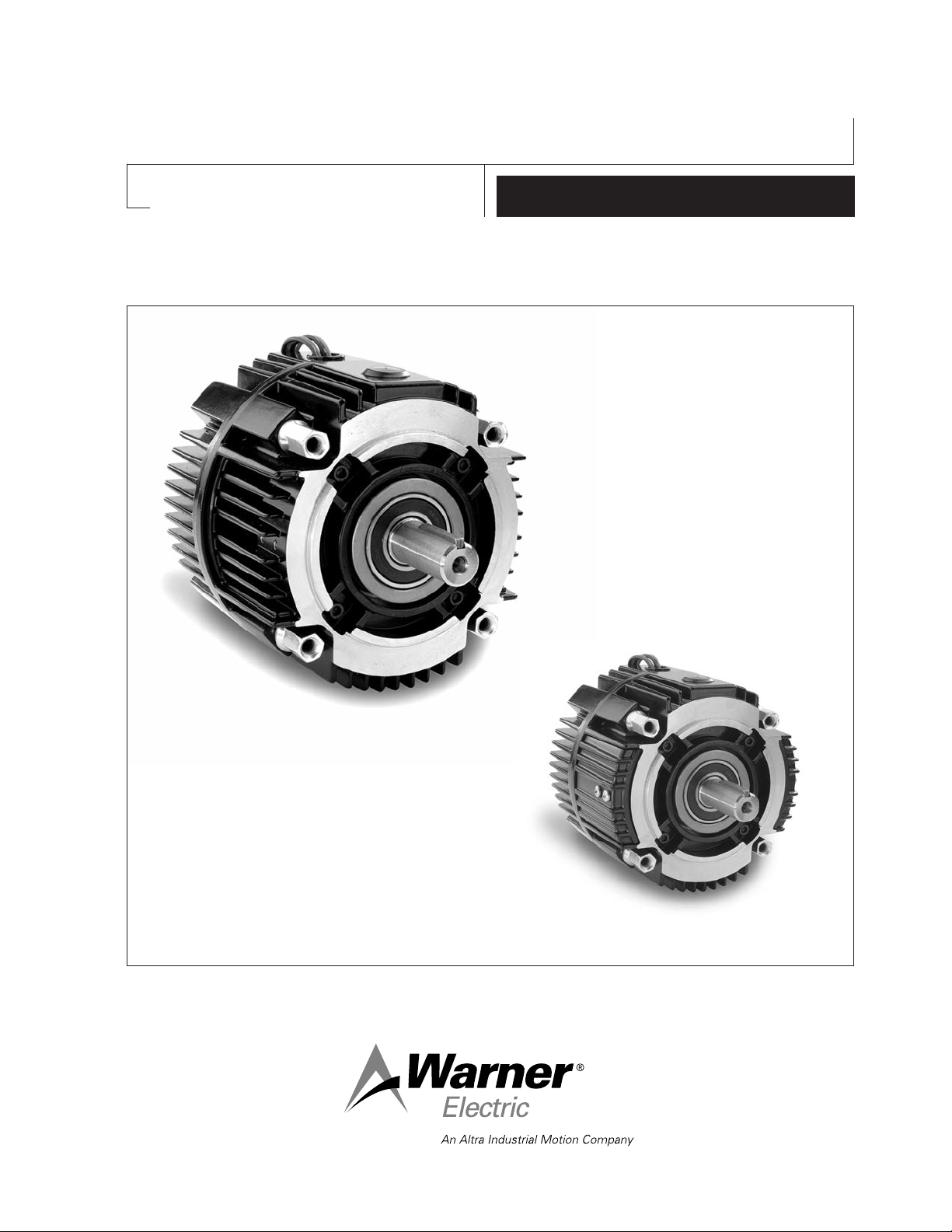
Clutch/Electrically Released Brake UniModule
UM-50FBC, UM-100FBC, UM-180FBC
P-273-9
819-0530
Installation Instructions
Vented
Enclosed Version Optional
Page 2
Contents
Mounting to a C-Face Motor . . . . . . . .3
Mounting to a Reducer . . . . . . . . . . . . .4
Installing the Base Mount . . . . . . . . . . .4
Installing the Motor Mount Bracket . . .4
Mounting to other Power
Transmission Components . . . . . . . .5
Electrical Connections . . . . . . . . . . . . . .6
FB Brake Release Adjustment . . . . . . .6
Troubleshooting-Electrical . . . . . . . . . . .7
Troubleshooting-Mechanical . . . . . . . . .7
Enclosed UniModule Option . . . . . . . . .9
The 2030FBC UniModule is designed to mount
using a base mounting kit. This allows the
modules to be mounted as a separate drive unit
driven from the prime mover by V-belts, chain
and sprockets, couplings, timing belts and other
standard power transmission components.
(For UniModule sizes 210 and 215 please refer
to Warner Electric manual P-273-2)
For These UM FBC Combinations Use These
Installation Steps:
Failure to follow these
instructions may result in product damage,
equipment damage, and serious or fatal
injury to personnel.
The equipment covered by
this installation manual must be installed in
accordance with these instructions. Failure
to do so may damage the equipment and
void the warranty.
Warner Electric UniModules are designed to
National Electrical Manufacturers Association
(NEMA) standards. They can be mounted to
common NEMA C-Face motors and reducers as
well as common power transmission drive
components.
The 1020FBC UniModule is designed to mount
to the face of a C-Face motor as noted in
Table 1.
Corresponding
NEMA Frame Sizes
C-Face
UM Old New Shaft Pilot
Size NEMA NEMA Dia. Dia.
50 56 C 48 Y 5/8" 4-1/2"
100 56 C 48 Y 5/8” 4-1/2”
180 182 C 143 TC 7/8" 4-1/2"
184 C 145 TC
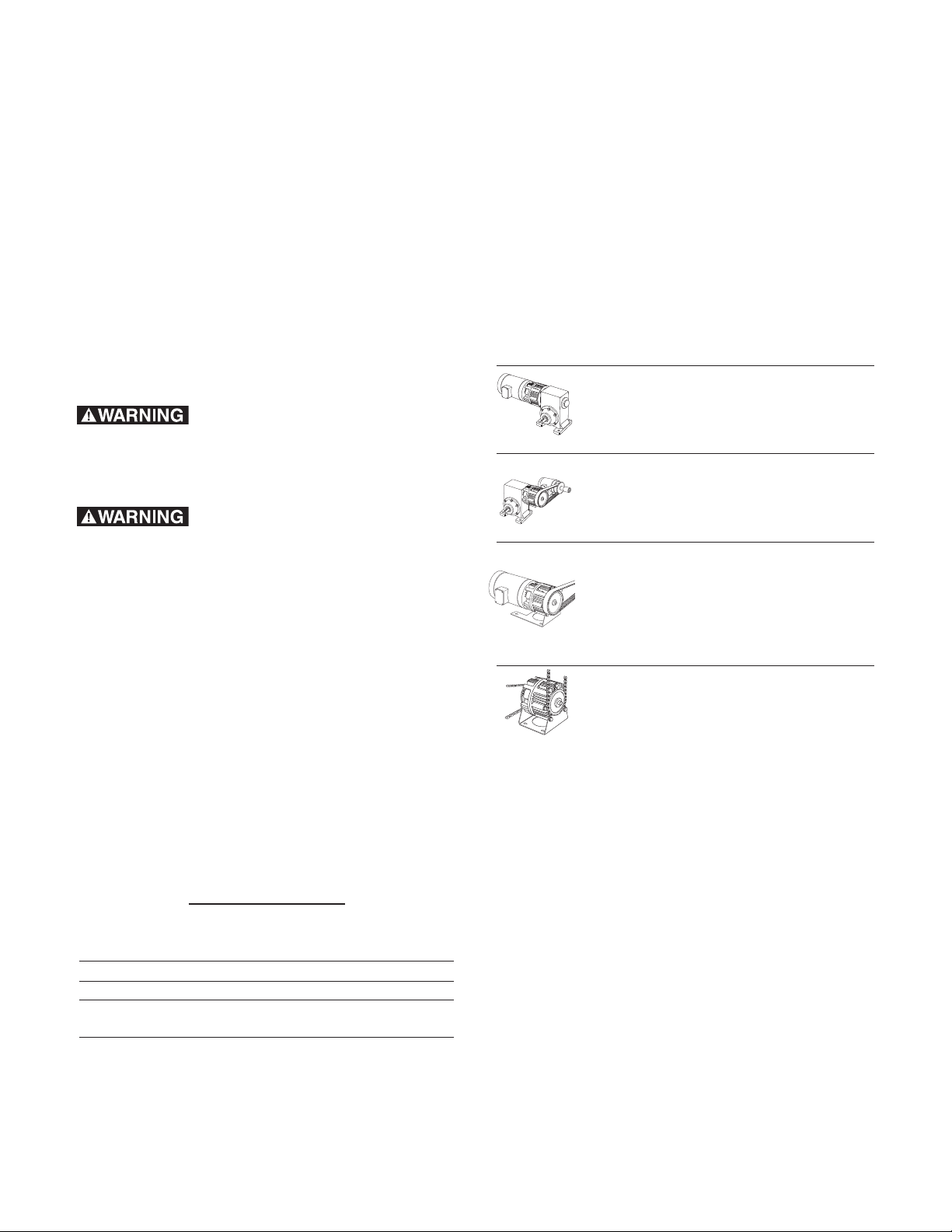
UniModule Clutch/Brake between
C-Face Motor and Reducer
1020FBC
UniModule Clutch/Brake
2030FBC
Motor Mount Module Clutch/Brake
on a C-Face Motor
1020FBC-M
Base Mounted
UniModule Clutch/Brake
2030FBC-B
Mounting to a Motor
Mounting to a Reducer
Electrical Connections
Brake Release Adjustment
Mounting to other
Power Transmission
Components
Electrical Connections
Brake Release Adjustment
Mounting to a Motor
Installing the Motor
Mount Bracket
Mounting to other
Power Transmission
Components
Electrical Connections
Brake Release Adjustment
Installing the Base Mount
Mounting to other
Power Transmission
Components
Electrical Connections
Brake Release Adjustment
Install your specific FBC UniModule
combination according to the installation steps
specified in the table. Use only those steps
indicated for each combination.
Table 1
Warner Electric • 800-825-9050 P-273-9 • 819-0530
2
Page 3
Mounting to a C-Face Motor
1. A hardened key is provided with the
mounting hardware for FBC UniModules.
Insert this key onto the motor shaft
(staking the key is necessary).
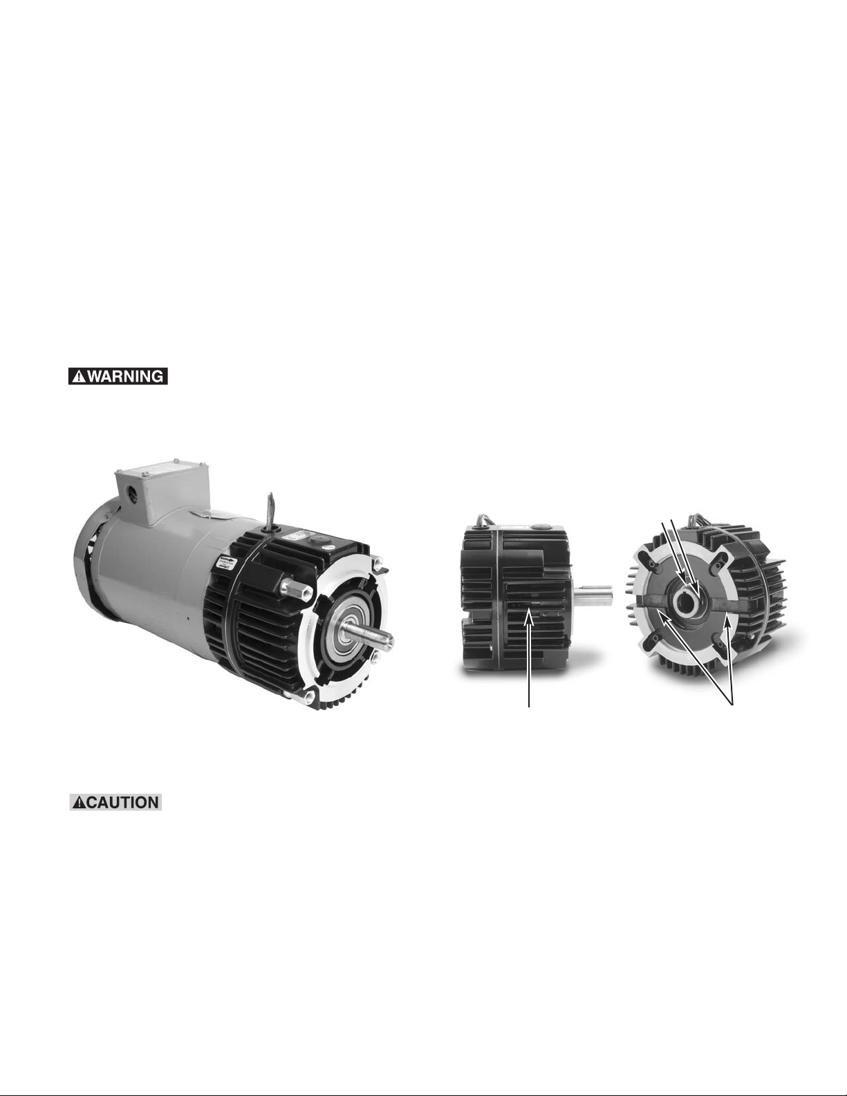
2. Align the keyway in the bore of the
UniModule to the key in the motor shaft
and slide the unit onto the motor shaft.
The normal alignment of the module to the
motor will be with the wire exit/conduit
box in the upright (12 o’clock) position as
shown in Figure 2.
alternately to ensure even alignment of the
module. Tighten them to 30-35 foot
pounds.
4. Next secure the clutch rotor and fan
assembly to the motor shaft by tightening
the two (2) setscrew as follows:
a. There are two (2) access slots on
either side of the UniModule. A long
Allen wrench can be used to tighten
the two setscrews (90° apart) which
secure the clutch rotor and fan
assembly to the motor shaft.
Do not hammer or force
the module into position. To do so may
damage bearings or cause the friction
faces to shift out of alignment.
Figure 2
b. Alternately align each setscrew with
one of the access slots by rotating the
clutch rotor and fan assembly through
one of the side vents with a small
screw driver taking care not to damage
the fan. (Figure 3a)
Set Screws
Side Vent
Access Slots
Figure 3a
c. Using a torque wrench and long Allen
If anti-fretting lubricant is
used on the motor shaft for future ease of
removal, ensure that any excess is wiped
off before unit assembly to avoid lubricant
contaminating the clutch or brake friction
faces.
socket, tighten the two (2) setscrews
to: (Figure 3b)
• Size 50: 80-85 inch pounds
(Requires 5/32 inch Allen wrench)
• Size 100 or 180: 40-45 inch pounds
(Requires 1/8 inch Allen wrench)
3. Secure the FBC UniModule to the motor
with the four (4) long mounting tie-bolts
provided. Tighten the four (4) bolts
Warner Electric • 800-825-9050 P-273-9 • 819-0530
3
Page 4

Figure 3b
Mounting to a Reducer
1. Warner Electric UniModules are furnished
with a hardened key pre-mounted on the
output shaft.
2. Align the output shaft and key of the
module with the corresponding bore and
keyway of the reducer. Slide the assembly
together as shown in Figure 4.
Installing the Base Mount
Model 2030FBC UniModule is designed to be
base mounted as shown in Figure 5.
Optional Base Mount Kit,
Warner Electric part numbers:
UM-50/100...........................5370-101-004
UM-180................................5370-101-002
Figure 5
Figure 4
3. Bolt the module to the reducer flange.
The four (4) bolts that are required
(3/8-16UNC2A) are typically provided with
the reducer. Tighten to 18-22 foot pounds
of torque.
1. The pilot diameters on each end of the
UniModule will mate with the pilot
diameters on the base.
2. Secure the base to the UniModule with the
four (4) bolts provided. Tighten to 18 to 22
foot pounds.
Installing the Motor Mount Bracket
A Motor Mount Bracket can be installed on
the output end of a 1020FBC UniModule to
provide a foot mounting for the complete
assembly of a UniModule and C-face motor.
Optional Motor Mount Kit,
Warner Electric part numbers:
UM-50/100............................5370-101-078
UM-180.................................5370-101-079
Warner Electric • 800-825-9050 P-273-9 • 819-0530
4
Page 5

1. Mount the bracket to the face of the
UniModule underneath the UniModule
and motor as shown in Figure 6. A pilot
diameter on the UniModule mates with
a pilot diameter on the bracket.
Figure 6
Overhung Load Data
(Shaft Side Load)
Overhung load data is provided in this manual
for the design engineer concerned with a
specific problem in this area. The maximum
A
2. Secure the motor bracket in place with
four (4) short bolts and washers provided.
Tighten to 18 to 22 foot pounds.
Mounting to other Power
Transmission Components
Couplings, pulleys, sprockets or
similar power transmission components can be mounted to the input and output shafts of a UniModule.
When mounting a pulley or
sprocket, ensure that the key is fully
engaged within the device hub or bushing.
Confirm that the belt or chain tightness
meets the maximum side load capability of
the UniModule shown in
Table 2.
R
allowable overhung load which can be applied
to the shaft of an UniModule may be
determined by the use of the accompanying
chart.
UniModule Housing Face Load Rating
UM-50 1" (Center of Shaft) 177
UM-100 1” (Center of Shaft) 192
UM-180 1" (Center of Shaft) 192
Distance Load is
Applied from Maximum
"A" Inches "R" Lbs.
2" (End of Shaft) 123
3" 95
2” (End of Shaft) 134
3” 104
2" (End of Shaft) 134
3" 104
Table 2
Warner Electric • 800-825-9050 P-273-9 • 819-0530
5
Page 6

Electrical Connections
To avoid injury (or even death), always
make certain all power is off before
attempting to install or service this device
or any electrical equipment.
The conduit connection hole in the
UniModules are threaded for standard ½
inch conduit connection. UniModule FBC
clutches and brakes operate on DC voltage.
Warner Electric offers a complete line of
electronic controls to meet the needs of
almost any clutch/brake application. Each
Warner Electric control will show the proper
wiring connections for its use.
Control Requirements for (FB) Fail
Safe Brakes
for standard ½ inch conduit connectors.
FB Brake Release
Adjustment
Instructions for setting the optimum release
voltage of permanent magnet applied/
electrically released brakes.
The following procedure will result in the
brake releasing and allowing the load to be
free to move. Be sure the load is in a safe
condition before proceeding with
this process.
In a permanent magnet applied/electrically
released brake, the attractive force between
the brake surfaces is created by permanent
magnets. The brake is electrically released by
applying DC power to the electro-magnetic
coil in the brake that opposes the permanent
magnets.
Electrically Released Permanent Magnet
Brakes must use one of Warner Electric’s
adjustable power supplies. See the Service
Installation sheet included with the power
supply for connection information.
Note: All Electrically Released Permanent
Magnet Modules are polarity sensitive.
Therefore, the (+) red wire must be connected
to the positive terminal and the (-) black wire
to the negative terminal. Potentiometer control
will then provide adjustment for the proper
brake release point.
When switching a 1020FBC or 2030FBC
power must be applied to both the clutch and
FB brake simultaneously to engage the clutch
and at the same time release the brake.
If a Conduit Box is desired, Warner Electric
Conduit Box Kit, part number 5370-101-042,
can be purchased separately. The Conduit
Box provides two conduit connection holes
Warner Electric • 800-825-9050 P-273-9 • 819-0530
6
Electrically released brakes are polarity
sensitive: the positive lead of the power
supply must be connected to the positive
(red) lead of the brake and the negative lead
of the power supply must be connected to
the negative (black) lead of the brake.
The power supply applied to the brake must
also be adjustable so that the optimum
release voltage for each individual brake
can be determined and set.
The following procedure describes how to set
the adjustable power supply to the optimum
release point of the brake. A volt-meter is
required to perform the procedure.
No power is applied to motor during this
procedure. Power normally supplied by
motor to brake control should be supplied
by alternate method.
1. With power off, connect the positive lead
Page 7

of the power supply to the positive (red)
lead of the brake and the negative lead of
the power supply to the negative (black)
lead of the brake.
2. Connect a volt-meter to measure the
voltage applied across the brake.
3. Adjust the power supply to its lowest
possible output, and then energize the
power supply to apply power to the brake
only.
requires DC power to function. If power is not
reaching the clutch or brake, the clutch will
not engage and the brake will not disengage.
A good practice to follow is to check for
power at the lead wires to the clutch or brake
using a voltmeter.
• If power is present in the proper voltage
and current, then skip ahead to the
Mechanical Troubleshooting section.
• If power is not present, inspect the lead
wires for breaks or cuts.
4. Starting from the low voltage point, slowly
increase the applied voltage while visually
watching the brake armature through one
of the vent slots and fan slot on either side
of the module until the brake armature
disengages from the brake magnet. Note
and record this voltage reading.
5. Add twenty (20) volts for a 90 volt brake
and ve (5) volts for a 24 volt brake to this
reading and set the supply to this level.
This will be the proper release voltage for
your setup.
6. With the brake energized, spin the output
shaft by hand to insure that it turns freely.
If a scraping sound is noted when the
output shaft is spun, it means an
armature is dragging slightly. This needs to
be corrected by repeating brake release
adjustment steps 1-5 above and/or
performing armature airgap adjustment as
described in the Troubleshooting –
Mechanical section of this instruction.
• If the wires are intact, the problem may
be with the power supply or the switch.
• Using a voltmeter, check to see that
voltage is leaving the power supply and
that the switch is sending power to the
Electrical Coil Data
Clutch Brake Clutch Brake
Voltage–D.C. 90 90 24 24
Resistance UM-50 452 429 31.8 28.8
(OHMS) UM-100/180 392 308 26.7 21.7
Current UM-50 .20 .21 .76 .83
(Ampheres) UM-100/180 .23 .29 .90 1.1
Power UM-50 18 19 19 20
(WATTS) UM-100/180 21 27 22 27
Coil Build Up UM-50 52 40 52 40
clutch or brake.
• Finally, if there is no power leaving the
switch or power supply, check the
incoming AC power to ensure that it is
reaching the power supply.
Troubleshooting - Electrical
If a UniModule is not functioning properly it is
best to check for these problems before
replacing it.
Troubleshooting - Mechanical
Both clutch and FB brake armatures are
equipped with an AutogapTMassembly that
maintains the proper airgap between friction
faces through the life of the product. Each
A standard UniModule FBC clutch/brake
Warner Electric • 800-825-9050 P-273-9 • 819-0530
UniModule is airgap adjusted and pre-
7
Page 8
burnished at the factory, but the airgaps
can shift as a result of rough handling during
shipping and installation.
An airgap that is too large can prevent the
armature from engaging. An airgap that is
too small can cause the armature to rub
continuously, causing higher running
temperatures and decreased wear life.
To reset the airgaps, you will need to access
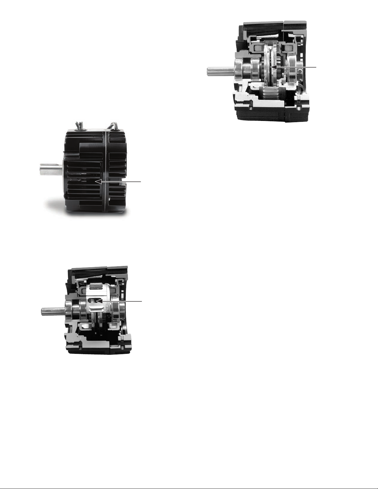
Figure 9
Figure 7
the armatures.
Looking
through the vents on either side of the housing, you will see the fan on the clutch rotor.
Figure 8
Rotate the fan
(input) until you
see the 1/2 x 1 inch window on the outer
periphery of the fan. Through this window,
you will be looking between the two armatures of the clutch and brake. (Figures 7
& 8)
If either armature is too far away from its
mating friction suface, it is possible to move it
back into adjustment using a flat blade
screwdriver. (Figure 9)
Note: When resetting the clutch or FB brake
armature airgap, both the clutch and brake
must be released (the brake energized, and
the clutch not energized).
This is a three step process.
1. Simply slide the screwdriver through
the window. By twisting the screwdriver, it
works as a wedge to apply pressure on
the back of the armature pushing it
toward its mating friction surface.
Warner Electric • 800-825-9050 P-273-9 • 819-0530
8
Page 9

Mechanical Data
UM-50FBC UM-100/180FBC
Static Torque - lb. ft. 16 30
Maximum Speed - rpm 3600 3600
Average Weight-lbs.
1020 15.6 18.7
2030 18.4 21.7
Inertia - WR - lb.ft.
Configuration 50 100/180
1020 input .021 .047
1020 output .0195 .050
2030 input .021 .048
2030 output .0195 .050
2
Enclosed UniModule Option
If an Enclosed UniModule is required, an
optional Cover Kit, Warner Electric part
number 5370-101-076, can be purchased
separately to enclose the open vents in the
housing.
Each Cover Kit includes two (2) vent covers
and four (4) screws needed to convert a
vented UniModule to an enclosed design
(non-washdown) as shown in Figure 10.
Figure 10
Note: When using this Cover Kit to enclose
the module the vent covers should be
assembled as the final step.
Notes:
Visit Warner Electric’s website at
www.warnerelectric.com for dimensional
drawings, weights, inertias, and a complete
offering of our products including clutches,
brakes and clutch/brake controls and
service parts.
In addition, Warner Electric module
products, controls, and service parts
information can be found in our catalog
P-1234-WE. Call 815-389-3771 to request any
of our catalogs.
Warner Electric • 800-825-9050 P-273-9 • 819-0530
9
Page 10

Warranty
Warner Electric LLC warrants that it will repair or replace (whichever it deems advisable) any
product manufactured and sold by it which proves to be defective in material or workmanship
within a period of one (1) year from the date of original purchase for consumer, commercial or
industrial use.
This warranty extends only to the original purchaser and is not transferable or assignable without
Warner Electric LLC’s prior consent.
Warranty service can be obtained in the U.S.A. by returning any defective product, transportation
charges prepaid, to the appropriate Warner Electric LLC factory. Additional warranty information
may be obtained by writing the Customer Satisfaction Department, Warner Electric LLC, 449
Gardner Street, South Beloit, Illinois 61080, or by calling 815-389-3771.
A purchase receipt or other proof of original purchase will be required before warranty service is
rendered. If found defective under the terms of this warranty, repair or replacement will be made,
without charge, together with a refund for transportation costs. If found not to be defective, you
will be notified and, with your consent, the item will be repaired or replaced and returned to you at
your expense.
This warranty covers normal use and does not cover damage or defect which results from
alteration, accident, neglect, or improper installation, operation, or maintenance.
Some states do not allow limitation on how long an implied warranty lasts, so the above limitation
may not apply to you.
Warner Electric LLC’s obligation under this warranty is limited to the repair or replacement of the
defective product and in no event shall Warner Electric LLC be liable for consequential, indirect,
or incidental damages of any kind incurred by reason of the manufacture, sale or use of any
defective product. Warner Electric LLC neither assumes nor authorizes any other person to give
any other warranty or to assume any other obligation or liability on its behalf.
WITH RESPECT TO CONSUMER USE OF THE PRODUCT, ANY IMPLIED WARRANTIES WHICH
THE CONSUMER MAY HAVE ARE LIMITED IN DURATION TO ONE YEAR FROM THE DATE OF
ORIGINAL CONSUMER PURCHASE. WITH RESPECT TO COMMERCIAL AND INDUSTRIAL
USES OF THE PRODUCT, THE FOREGOING WARRANTY IS IN LIEU OF AND EXCLUDES ALL
OTHER WARRANTIES, WHETHER EXPRESSED OR IMPLIED BY OPERATION OF LAW OR
OTHERWISE, INCLUDING, BUT NOT LIMITED TO, ANY IMPLIED WARRANTIES OF
MERCHANTABILITY OR FITNESS.
Some states do not allow the exclusion or limitation of incidental or consequential damages, so
the above limitation or exclusion may not apply to you. This warranty gives you specific legal
rights and you may also have other rights which vary from state to state.
Changes in Dimensions and Specifications
All dimensions and specifications shown in Warner Electric catalogs are subject to change without
notice. Weights do not include weight of boxing for shipment. Certified prints will be furnished
without charge on request to Warner Electric.
Warner Electric LLC
31 Industrial Park Road • New Hartford, CT 06057
815-389-3771
www.warnerelectric.com
P-273-9 • 819-0530 6/12 Printed in USA
• Fax: 815-389-2582
 Loading...